
SRTHERMDUCT - Computer accessory Tripp Lite - Free user manual and instructions
Find the device manual for free SRTHERMDUCT Tripp Lite in PDF.


| Product Type | Venting and Cable Management System |
| Brand | Tripp Lite |
| Model | SRTHERMDUCT |
| Compatible Rack Sizes | Standard 42U and 48U enclosures |
| Height Adjustment Range | 20 to 34 inches (flat to full height) |
| Components Included | Cable Access Panel, Chimney Base, Adjustable Chimney Slider |
| Hardware Included | 4x M8 screws, 4x M4 screws, 16x M4 nuts |
| Additional Sealing Materials | Tubular and Flat Door Seals, Magnetic Vinyl Sheets |
| Material | Steel |
| Weight | Approximately 15-20 lbs (estimated) |
| Installation Requirement | Two people recommended due to weight |
| Warranty | 5-year limited warranty |
| Intended Use | Vents heat from rack enclosure into return air duct |
| Energy Savings | Reduces facility cooling and energy costs |
| Cable Management | Cable access panel allows cable routing |
| Height Locking Mechanism | Locking pins for secure adjustment |
| Sealing Requirement | Rear doors must be sealed for proper airflow |
| Maintenance | Clean with dry cloth; no lubrication required |
| Safety Warning | Do not install alone; use two people |
Frequently Asked Questions - SRTHERMDUCT Tripp Lite
User questions about SRTHERMDUCT Tripp Lite
0 question about this device. Answer the ones you know or ask your own.
Ask a new question about this device
Download the instructions for your Computer accessory in PDF format for free! Find your manual SRTHERMDUCT - Tripp Lite and take your electronic device back in hand. On this page are published all the documents necessary for the use of your device. SRTHERMDUCT by Tripp Lite.
USER MANUAL SRTHERMDUCT Tripp Lite
SmartRack™ Accessories
Model: SRTHERMDUCT
Table of Contents
Introduction 2
Parts List 2
Installation 3
Warranty & Warranty Registration 7
Introduction
Tripp Lite's SRTHERMDUCT is a 3 piece, adjustable venting and cable management system that will fit on top of standard 42 or 48U rack enclosures. The SRTHERMDUCT allows heat built up in a typical rack configuration to be vented upwards into your facility's return air duct or other standard ventilation system, helping your equipment perform at its peak while reducing your facility's cooling and energy costs.
Parts List
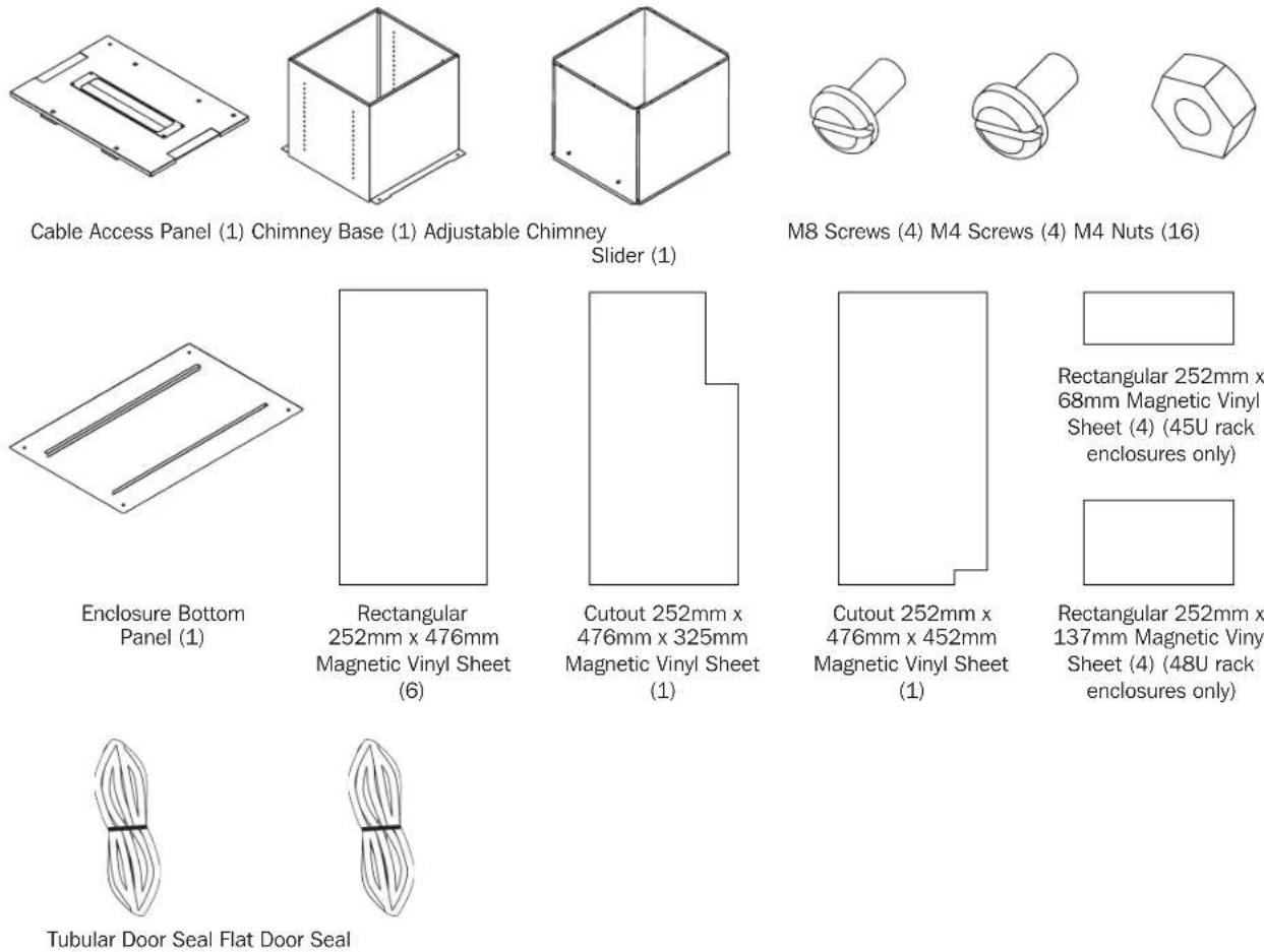
Cable Access Panel (1) Chimney Base (1) Adjustable Chimney
Slider (1)
M8 Screws (4) M4 Screws (4) M4 Nuts (16)
Installation
Assembling the Chimney Base
1 Position the 4 side panels of the Chimney Base in accordance with Diagram 1 and secure the attachments with 8 of the M4 nuts that screw onto the pre-installed threaded posts.
Once assembled, this piece can be put aside for later use.

natural_image
Isometric line drawing of a rectangular metal enclosure with internal partitions and mounting feet (no text or symbols)Assembling the Adjustable Chimney Slider
2 Position the 4 side panels of the Adjustable Chimney Slider in accordance with Diagram 2 and secure the attachments with the remaining 8 M4 nuts that screw onto the pre-installed threaded posts.
Once both the Chimney Base and Slider have been assembled you can move on to stacking.

natural_image
Isometric line drawing of a 3D rectangular frame structure with labeled points (no text or symbols)Stacking the Chimney
3 With both the Chimney Base and Adjustable Chimney Slider assembled, position and fit the slider on top of the base.
4 The holes in the sides of the Chimney Base and locking pins in the sides of the Chimney Slider allow the chimney to be adjustable in height with a range of 20" (flat, no height) to 34" (adjusted, full height). For installation purposes, it is recommended to initially stack the two pieces in the 20" (flat, no height) position until installed on the rack enclosure. To do so, pull out the four locking pins and slide the Chimney Slider all the way down over the Chimney Base into the 20" position as seen in Diagrams 3 and 4.

Installation continued
Installing the Enclosure Bottom Panel
5 Install the bottom panel to the enclosure using the 4 provided M4 screws. Slide the panel underneath your enclosure and have another person hold it up in place while you start the screws from the inside of the enclosure. The M4 screws will not require nuts as the bottom panel provides 4 threaded holes.
You can also install this panel from the inside of the enclosure. To do so, you must remove all the vertical rails, then simply lay the bottom panel down onto the bottom of the enclosure frame. Screws do not need to be used in this configuration.

natural_image
Isometric line drawing of a building interior with structural beams and supports (no text or symbols)Installing the Cable Access Cover
6 Place the entire panel onto the top of your rack enclosure as shown in Diagram 6. Note: The SRTHERMDUCT will fit most standard rack installations, however, it is up to the user to determine the fitness and configuration of their rack enclosure before installation.

natural_image
Technical diagram of a mechanical assembly with an arrow indicating a component or process (no text or symbols present)Installing the Chimney
Once the Cable Access Cover has been placed on top of the rack enclosure you can install the chimney.

Warning! Heavy! Do not attempt to install alone! Use at least two people for the installation!
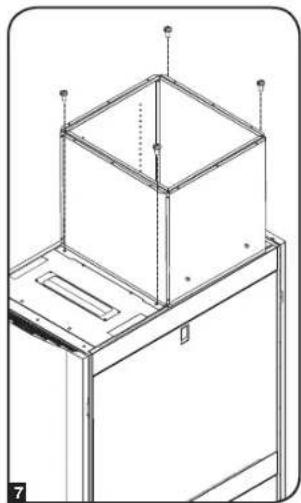
7 To install the chimney, attach 2 of the feet to the Cable Access Cover and the other 2 feet to the frame of the rack enclosure using the 4 M8 screws as seen in diagram 7.
8 Once the chimney has been secured to the rack, you can adjust the height of the chimney. To do so, pull up on the Adjustable Chimney Slider until you have reached the desired height. Lock the Slider in place by pushing in the 4 locking pins. (See Diagram 8.)
natural_image
Technical line drawing of a mechanical assembly with a square frame and mounting base (no text or symbols)
Installation continued
Sealing the Rear Doors of the Enclosure
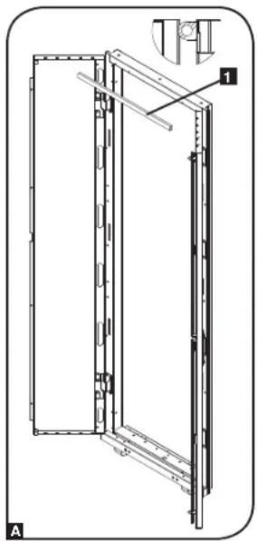
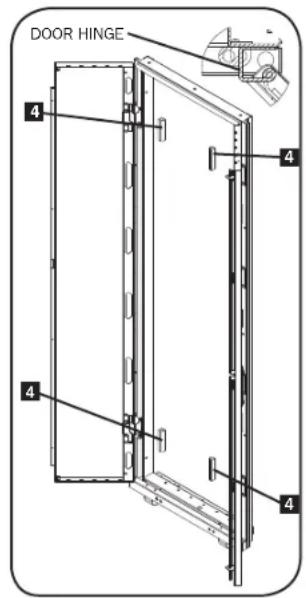
Install the included Tubular and Flat Door Seals and Magnetic Vinyl Sheets to the rear doors of the rack enclosure. This is necessary to ensure proper air flow through the front of the enclosure and up the chimney. Remove all rubber grommets and bumpers before installing the Door Seals and the Magnetic Vinyl Sheets.
Cut the Door Seals into the sections required for your rack. The following table gives the location (by number) and recommended measurement for each section.
| Cut Number Required Length (mm) for 42U Rack Length (mm) for 45U Rack Length (mm) for 48U Rack | |||
| 1 2 544 544 544 | |||
| 2 4 178 178 178 | |||
| 3 2 1334 1469 1604 | |||
| 4 4 95 95 95 | |||
| 5* 1 1740 1872 2007 | |||
*Use Flat Door Seal
Install the Tubular and Flat Door Seals as shown A. The inserts depict the seal installation in cross section:
natural_image
Technical line drawing of a door frame structure with mounting flanges and a labeled component (no text or symbols present)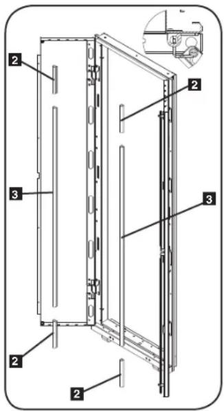

natural_image
Technical line drawing of a door frame structure with mounting brackets and a small inset showing a cabinet (no text or symbols)Installation continued
Sealing the Rear Doors of the Enclosure continued
After installing the Tubular Door Seal, attach the Magnetic Vinyl Sheets to the rear doors as shown B.
1 Rectangular 252mm x 476mm Magnetic Vinyl Sheet
2 Cutout 252mm x 476mm x 325mm Magnetic Vinyl Sheet
3 Cutout 252mm x 476mm x 452mm Magnetic Vinyl Sheet
4 Rectangular 252mm x 137mm Magnetic Vinyl Sheet (48U rack enclosure only. For 45U units, use 252mm x 68mm Magnetic Vinyl Sheet instead)
Note: The drawing shows the installation scheme for a 48U enclosure. For a 42U enclosure, the Rectangular 252mm x 137mm Magnetic Vinyl Sheets 4 are not required.

Warranty & Warranty Registration
Limited Warranty
Seller warrants this product, if used in accordance with all applicable instructions, to be free from original defects in material and workmanship for a period of 5 years from the date of initial purchase. If the product should prove defective in material or workmanship within that period, Seller will repair or replace the product, in its sole discretion.
THIS WARRANTY DOES NOT APPLY TO NORMAL WEAR OR TO DAMAGE RESULTING FROM ACCIDENT, MISUSE, ABUSE OR NEGLECT. SELLER MAKES NO EXPRESS WARRANTIES OTHER THAN THE WARRANTY EXPRESSLY SET FORTH HEREIN. EXCEPT TO THE EXTENT PROHIBITED BY APPLICABLE LAW, ALL IMPLIED WARRANTIES, INCLUDING ALL WARRANTIES OF MERCHANTABILITY OR FITNESS, ARE LIMITED IN DURATION TO THE WARRANTY PERIOD SET FORTH ABOVE; AND THIS WARRANTY EXPRESSLY EXCLUDES ALL INCIDENTAL AND CONSEQUENTIAL DAMAGES. (Some states do not allow limitations on how long an implied warranty lasts, and some states do not allow the exclusion or limitation of incidental or consequential damages, so the above limitations or exclusions may not apply to you. This Warranty gives you specific legal rights, and you may have other rights which vary from jurisdiction to jurisdiction.)
Tripp Lite; 1111 W. 35th Street; Chicago IL 60609; USA
WARNING: The individual user should take care to determine prior to use whether this device is suitable, adequate or safe for the use intended. Since individual applications are subject to great variation, the manufacturer makes no representation or warranty as to the suitability or fitness of these devices for any specific application.
WARRANTY REGISTRATION
Visit www.triplite.com/warranty today to register the warranty for your new Tripp Lite product. You'll be automatically entered into a drawing for a chance to win a FREE Tripp Lite product!*
* No purchase necessary. Void where prohibited. Some restrictions apply. See website for details.
WARNING!
Use of this equipment in life support applications where failure of this equipment can reasonably be expected to cause the failure of the life support equipment or to significantly affect its safety or effectiveness is not recommended. Do not use this equipment in the presence of a flammable anesthetic mixture with air, oxygen or nitrous oxide.
Tripp Lite follows a policy of continuous improvement. Product specifications are subject to change without notice.

1111 W. 35th Street, Chicago, IL 60609 USA
www.tripplite.com/support

- SmartRack™ Accessories
- Table of Contents
- Introduction
- Parts List
- Installation
- Assembling the Chimney Base
- Assembling the Adjustable Chimney Slider
- Stacking the Chimney
- Installation continued
- Installing the Enclosure Bottom Panel
- Installing the Cable Access Cover
- Installing the Chimney
- Warning! Heavy! Do not attempt to install alone! Use at least two people for the installation!
- Sealing the Rear Doors of the Enclosure
- Sealing the Rear Doors of the Enclosure continued
- Warranty & Warranty Registration
- Limited Warranty
- WARRANTY REGISTRATION
- WARNING!
Brand : Tripp Lite
Model : SRTHERMDUCT
Category : Computer accessory