
F30WC19EC - Home Appliance FRIGIDAIRE - Free user manual and instructions
Find the device manual for free F30WC19EC FRIGIDAIRE in PDF.

| Product Type | Under Cabinet Range Hood |
| Brand | Frigidaire |
| Model | F30WC19EC |
| Installation | Ducted or Non-Ducted (Ductfree) |
| Width | 30 inches |
| Mounting Height | 18-24 inches above cooking surface |
| Power Supply | 120V, 60Hz, grounded |
| Fan Speeds | 2 speeds (High and Low) |
| Lighting | 75W max incandescent bulb (not included) |
| Controls | Rotary knobs for fan and light |
| Filter Type | Aluminum mesh filter, dishwasher safe |
| Duct Options | 3-1/4" x 10" rectangular or 7" round |
| Non-Ducted Kit | Non-ducted filter purchased separately |
| Motor Protection | Thermal overload auto shut-off |
| Materials | Metal ductwork required; painted finish |
| Cleaning | Mild detergent for exterior; filter dishwasher safe |
| Warranty | 1 year limited warranty |
| Weight | Approximately 30 lbs |
| Dimensions (WxDxH) | 30" x 17.5" x 5.5" (approx) |
| Spare Parts Available | Filter, motor assembly, light socket, switch, damper |
Frequently Asked Questions - F30WC19EC FRIGIDAIRE
User questions about F30WC19EC FRIGIDAIRE
0 question about this device. Answer the ones you know or ask your own.
Ask a new question about this device
Download the instructions for your Home Appliance in PDF format for free! Find your manual F30WC19EC - FRIGIDAIRE and take your electronic device back in hand. On this page are published all the documents necessary for the use of your device. F30WC19EC by FRIGIDAIRE.
USER MANUAL F30WC19EC FRIGIDAIRE
natural_image
Line drawing of a standard front-end box with ventilation slots and a label (no text or symbols)READ AND SAVE THESE INSTRUCTIONS
For Non-ducted (Ductfree) Installation:
a) Purchase non-ducted filter separately.
b) Remove and discard damper/duct connector and louver cover (See Step 4) in "Prepare the Hood," Page 2.
c) Follow all steps except steps inside dotted lines.
For Ducted Installation:
Follow all steps, including steps inside dotted lines.
WARNING

TO REDUCE THE RISK OF FIRE, ELECTRIC SHOCK, OR INJURY TO PERSONS, OBSERVE THE FOLLOWING:
- Use this unit only in the manner intended by the manufacturer. If you have questions, contact the manufacturer at the address or telephone number listed in the warranty.
- Before servicing or cleaning unit, switch power off at service panel and lock the service disconnecting means to prevent power from being switched on accidentally. When the service disconnecting means cannot be locked, securely fasten a prominent warning device, such as a tag, to the service panel.
- Installation work and electrical wiring must be done by a qualified person(s) in accordance with all applicable codes and standards, including fire-rated construction codes and standards.
- Sufficient air is needed for proper combustion and exhausting of gases through the flue (chimney) of fuel burning equipment to prevent backdrafting. Follow the heating equipment manufacturer's guideline and safety standards such as those published by the National Fire Protection Association (NFPA), and the American Society for Heating, Refrigeration and Air Conditioning Engineers (ASHRAE), and the local code authorities.
- When cutting or drilling into wall or ceiling, do not damage electrical wiring and other hidden utilities.
- Ducted fans must always be vented to the outdoors.
- Do not use this unit with any solid-state speed control device.
- To reduce the risk of fire, use only metal ductwork.
- Use with approved cord-connection kit only.
- This unit must be grounded.
- Never leave surface units unattended at high settings. Boilovers cause smoking and greasy spillovers that may ignite. Heat oils slowly on low or medium settings.
- Always turn hood ON when cooking at high heat or when cooking flaming foods.
- Clean ventilation fans frequently. Grease should not be allowed to accumulate on fan or filter.
- Use proper pan size. Always use cookware appropriate for the size of the surface element.
TO REDUCE THE RISK OF A RANGE TOP GREASE FIRE:
WARNING

TO REDUCE THE RISK OF INJURY TO PERSONS IN THE EVENT OF A RANGE TOP GREASE FIRE, OBSERVE THE FOLLOWING:\*
- SMOTHER FLAMES with a close-fitting lid, cookie sheet, or metal tray, then turn off the burner. BE CAREFUL TO PREVENT BURNS. If the flames do not go out immediately, EVACUATE AND CALL THE FIRE DEPARTMENT.
- NEVER PICK UP A FLAMING PAN - You may be burned.
- DO NOT USE WATER, including wet dishcloths or towels - a violent steam explosion will result.
- Use an extinguisher ONLY if:
A. You know you have a Class ABC extinguisher and you already know how to operate it.
B. The fire is small and contained in the area where it started.
C. The fire department is being called.
D. You can fight the fire with your back to an exit.
* Based on "Kitchen Fire Safety Tips" published by NFPA.
CAUTION

- For general ventilating use only. Do not use to exhaust hazardous or explosive materials and vapors.
- To avoid motor bearing damage and noisy and/or unbalanced impellers, keep drywall spray, construction dust, etc. off power unit.
- Your hood motor has a thermal overload which will automatically shut off the motor if it becomes overheated. The motor will restart when it cools down. If the motor continues to shut off and restart, have the hood serviced.
- For best capture of cooking impurities, your range hood should be mounted 18-24" above the cooking surface.
- Please read specification label on product for further information and requirements.
INSTALLER: Leave This Manual With the Homeowner.
HOMEOWNER: Use and Care Information on Page 5.
TOOLS AND MATERIALS REQUIRED
TOOLS
Drill, electric or ratchet drive
□ 1-1/4" Spade bit
☐ Common head and phillips head screwdriver
□ Pliers
☐ Tape measure or ruler and pencil
For Ducted Installations ONLY:
□ Saber saw or drywall saw
Metal snips
MATERIALS
☐ Electrical wiring and supplies of type to comply with local codes
□ Roof or wall cap
□ Roof cement or caulk
□ Duct and duct tape
For Installation on Kitchen Cabinets with Recessed Bottoms Only:
☐ Two 1" x 2" x 12" (approximate length) wood strips (purchase locally)
☐ Four 1-1/4" long flat head wood screws (purchase locally) to fasten strips to cabinet bottom
PLANNING DUCTWORK INSTALLATION
Begin planning ductwork by deciding where the duct will run between the range hood and the outside. For best performance, use the shortest possible duct run and a minimum number of elbows. There are several choices shown - FIGS. 1A - 1E.
In more complex ducting situations, a 3-1/4" rectangular ducting range hood can be converted to a round duct by means of a transition.
FIG. 1A. Ducting directly through the wall (for range hoods mounted on an exterior wall). Shown are two ways to duct through an outside wall. If a wall cap is used directly off the back of the hood, special care must be taken to make sure that the damper in the damper/duct connector on the hood and damper in the wall cap do not interfere with each other when the hood is operating. This could result in either inadequate air delivery or back drafts. If this condition does exist, remove the hood damper flap. Sometimes when using a wall cap it is easier to duct vertically and then use an elbow as shown in FIG. 1B.
FIG. 1C. Ducting straight up through the roof using 3-1/4" x 10" rectangular duct. (For single story installations.)
FIG. 1D. Ducting between the ceiling joists (for multi-story installations) or through the soffit space above the cabinets (where the soffit connects to an outside wall).
FIG. 1E. Straight up through the roof using 3-1/4" x 10" to 6" round duct transition and 6" round duct (for single-story installations).
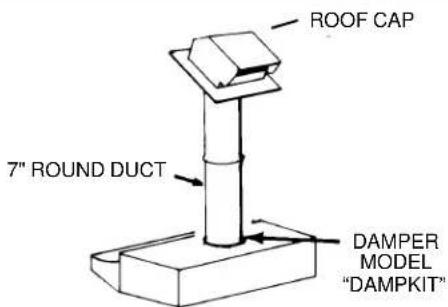
FIG. 1F. Straight up through the roof using 7" round duct (for single-story installations). Requires optional damper Model Damp Kit available from your local dealer.
FIG. 1A
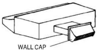
FIG. 1B
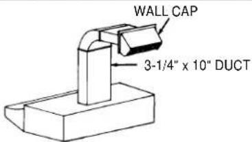
FIG. 1C
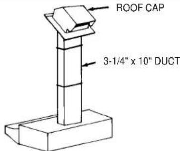
FIG. 1D
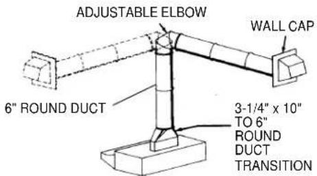
FIG. 1E

FIG. 1F
PREPARING THE RANGE HOOD
- Unpack hood and check contents. You should receive:
1 - Aluminum Filter
1 - 3-1/4" x 10" Damper/Duct Connector (mounted inside of hood for shipping only) (Save screws for mounting.)
1 - 7" Round Duct Plate (mounted on top of hood) (not shown) (Save screws for mounting.)
2. Remove 7" round duct plate from top of hood. Set duct plate aside - with mounting screws.
3. Remove wiring box cover. Under cover find:
For Ductfree Installations Only:
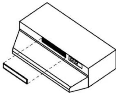
- For ductfree installation, remove louver cover from front (or inside) of hood. (FIG. 3)
NOTE
Louvers on front of hood must be open and visible for hood to function in ductfree mode.
5. Remove either top or rear electrical knockout depending upon whether wiring will enter hood from wall or cabinet. (FIG. 4)
DUCTED INSTALLATION ONLY
NOTE
Louver cover must be installed as shown in Figure 3 to function in ducted mode.
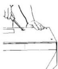
- Remove appropriate duct knockout on hood by inserting screwdriver into edge of knockout and breaking tabs holding knockout to hood. You may have to tap screwdriver with hammer to break tabs. Peel knockout back with pliers. (FIG. 5)
- Fit damper/duct connector over opening and secure in place with black sheet metal screws. (FIG. 6)
Hinge pins and damper/duct connector should be toward top of hood for ducting through wall or toward back of hood for ducting through cabinet above hood. Seal joint between damper/duct connector and hood with duct tape.
- 7" round ducted discharge only: Re-install 7" round duct plate removed in Step #2 under "PREPARING THE RANGE HOOD" section. For best performance, line up the 7" round duct plate with the 7" round opening on hood. Mount duct plate to hood with 2 screws from duct plate and 2 screws from 3 14 x 10" damper. Install a 7" round damper (purchase separately). Damper flap must open freely in direction of air flow (away from range hood).
PREPARING THE INSTALLATION LOCATION
NOTE
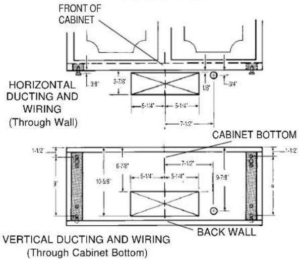
MOUNT HOOD SO THAT BOTTOM OF HOOD IS 18"-24" ABOVE COOKING SURFACE. TOP FRONT EDGE OF HOOD SHOULD BE FLUSH WITH FRONT OF CABINET FRAME.
IF DISTANCE BETWEEN WALL AND FRONT OF CABINET FRAME IS MORE THAN 12" THERE WILL BE A SPACE BETWEEN BACK OF HOOD AND WALL. THIS IS NORMAL.
OMIT STEP 9 if range hood will be installed under cabinets with flush bottom.
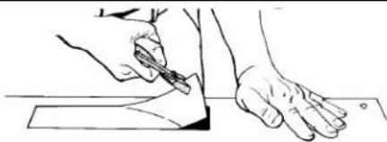
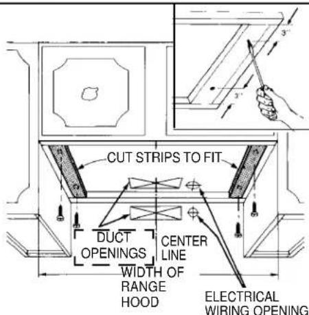
- (For installation on recessed bottom cabinets only) Attach a wood filler strip at each side of recessed area under cabinet. (Use two 1" x 2" strips cut to length.) If recess is more than 1" use thicker strips. Attach strips with 1-1/4" screws about 3" from each end. See FIG. 7.
- Measure and mark the following (FIGS. 7 & 8):
a) Electrical line opening
b) Duct opening
- Drill four pilot holes in corners of marked duct opening as shown and cut opening with saber saw or keyhole saw.
- Use 1-1/4" drill bit to drill opening for electrical connection in wall or cabinet.
- Hold hood up against cabinet bottom and trace keyhole slots onto cabinet bottom of filler strips.
- Screw the four supplied 7/8" wood screws for mounting the hood into the exact center of the narrow end of the keyhole slots marked underneath the cabinet. Allow 3/8" of the screws to project, so the hood can be fitted into place.
FIG. 2

FIG. 3
natural_image
Isometric line drawing of a mechanical device with no text or symbolsFIG. 4
natural_image
Line drawing of a hand holding a pen at a desk (no text or symbols)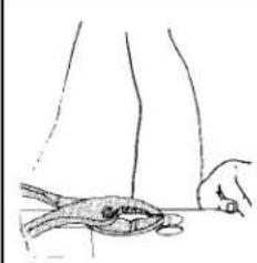
natural_image
Line drawing of a hand holding a small fish next to a line, with no text or symbols present.FIG. 5
natural_image
Line drawing of a hand holding a pen, poised to write on a surface (no text or symbols)FIG. 6

natural_image
Illustration of hands using a tool to adjust or install a mechanical component (no text or symbols visible)FIG. 7
INSTALLING THE DUCTWORK
NOTE
THESE INSTRUCTIONS WILL FOLLOW THE PLANS MADE ON PAGE 2. START AT THE EXTERIOR AND RUN THE DUCT BACK TO THE RANGE HOOD.
FOR BEST PERFORMANCE OF YOUR RANGE HOOD, USE THE SHORTEST POSSIBLE DUCT RUN AND A MINIMUM NUMBER OF ELBOWS.
NEVER VENT A RANGE HOOD INTO AN ATTIC SPACE BECAUSE A BUILDUP OF GREASE WILL BECOME A FIRE HAZARD.
USE ONLY METAL DUCTWORK (DO NOT USE PLASTIC DUCT). ASSEMBLE SECURELY SO THAT IN CASE OF A GREASE FIRE ON THE RANGE, THE FIRE WILL BE CONTAINED INSIDE METAL DUCT WORK.
IT IS A GOOD PRACTICE TO TAPE ALL DUCT CONNECTIONS, MAKING THEM BOTH SECURE AND AIR TIGHT.
- Follow appropriate directions below for type of duct work you are installing:
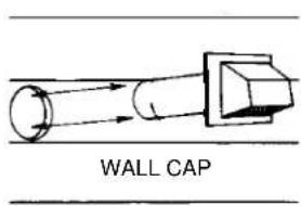
WALL CAPS (FIG. 9)
Use a saber saw to cut a hole slightly larger than duct so duct will line up easily with hood. Install casing strips on outside walls finished in siding. Assemble the duct work and tape all joints. Run duct work back to hood. Fasten wall cap to last section of duct and nail or screw cap to wall. Seal all around flange on wall cap with caulking compound. Make sure that enough duct runs into the room so that the duct will overlap the damper/duct connector by 3/4" when the hood is installed.
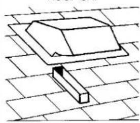
ROOF CAPS
Cut hole in roof slightly larger than duct so duct will line up easily with hood. Trim shingles around hole so that they will fit snugly around hood of cap when cap is installed. Assemble the duct work and tape all joints. Run the duct work down to hood. Trim duct parallel to roof pitch, leaving 3/4" of duct projecting above roof. Seal all around duct with roof cement. Install roof cap, inserting back edge of cap under shingles. Seal around cap with roof cement and seal all nail heads and shingles which were cut or lifted.
Make sure that enough duct runs into the room so that the duct will overlap the damper/duct connector by 3/4" when the hood is put into place.
FIG. 8
3-1/4" x 10" DUCT
7" ROUND DUCT
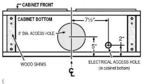
FIG. 9
ROOF CAP
natural_image
Simple line drawing of a rectangular block resting on a flat surface with diagonal grid lines (no text or symbols)INSTALLING THE RANGE HOOD
- Bring electrical cable through access hole drilled in wall or bottom of cabinet. Provide 6" wire leads and install proper connector for type of cable being used. Remove lock nut from connector and let prepared cable project through cabinet or wall opening so it is ready for installation into range hood. (FIG. 10)
- Position hood in place so that:
a) Electrical line is routed through appropriate knockout opening. This step will have to be accomplished while positioning hood. (FIG. 13)
b) Large part of keyhole mounting slots on hood fit onto hood mounting screws projecting from bottom of cabinet. (FIG. 11)
c) Damper/duct connector slides into duct work in wall or cabinet.
- Adjust hood so the front of hood is flush with cabinet front.
- Tighten the four hood mounting screws securely.
- Install locknut on electrical connector and tighten securely.
- Make electrical connection using wire nuts to connect white wire to white, black wire to black. Ground hood to prepared hole using green ground screw provided. (FIG. 12)
- Replace wiring box cover and screw. Make sure that all wiring is safely contained inside.
NOTE
For Ductfree Installations Only:
Install both filters. Make sure that ductfree filter (purchase separately) is next to fan assembly with blue side next to blade. Aluminum filter should be facing out.
USE AND CARE
SWITCHES
Right knob controls light.
Left knob controls blower. Rotate knob CLOCKWISE to turn blower ON to HIGH speed. Further CLOCKWISE rotation decreases blower speed. Rotate knob fully COUNTERCLOCKWISE (past HIGH speed) to turn fan OFF.
CLEANING
Finish Keep your range hood clean using a mild detergent suitable for painted surfaces.
Aluminum Filters should be cleaned frequently with a detergent solution to avoid grease build up. They are also dishwasher safe.
FILTER REMOVAL
Filters are removed by turning filter clip to the side and lifting filter or filters out. In ducted version, turn filter retaining clip to one side and place aluminum filter under embossed retaining tabs on back of fan housing. Turn filter clip so that the low end of clip holds single filter firmly in place. (FIG. 13)
In ductfree version, place both aluminum and ductfree filter under tabs on back of fan housing. Turn filter retaining clip so that high end holds both filters firmly in place. Make sure ductfree filter is next to fan assembly, with blue side next to fan blade, and aluminum filter is facing out.
NOTE: Make sure that arrows on filter retaining clip point toward back and front of hood.
LIGHT BULB REPLACEMENT
Light bulb (not supplied with hood) should be 75 watts maximum. The lens covering bulb is removed by pressing the two extending tabs together until they release from the retaining slots. (FIG. 14)
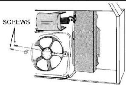
FAN ASSEMBLY REMOVAL
Be sure power is disconnected. Remove filters. Remove the two screws holding the motor bracket to the range hood and unplug the fan assembly. Be careful not to allow fan assembly to drop when the screws are removed. (FIG. 15).
FIG. 10

FIG. 11

FIG. 12

FIG. 13
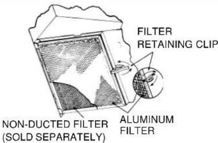
FIG. 14
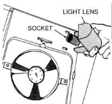
FIG. 15
SERVICE PARTS
F30WC, F36WC, & F42WC SERIES RANGE HOOD
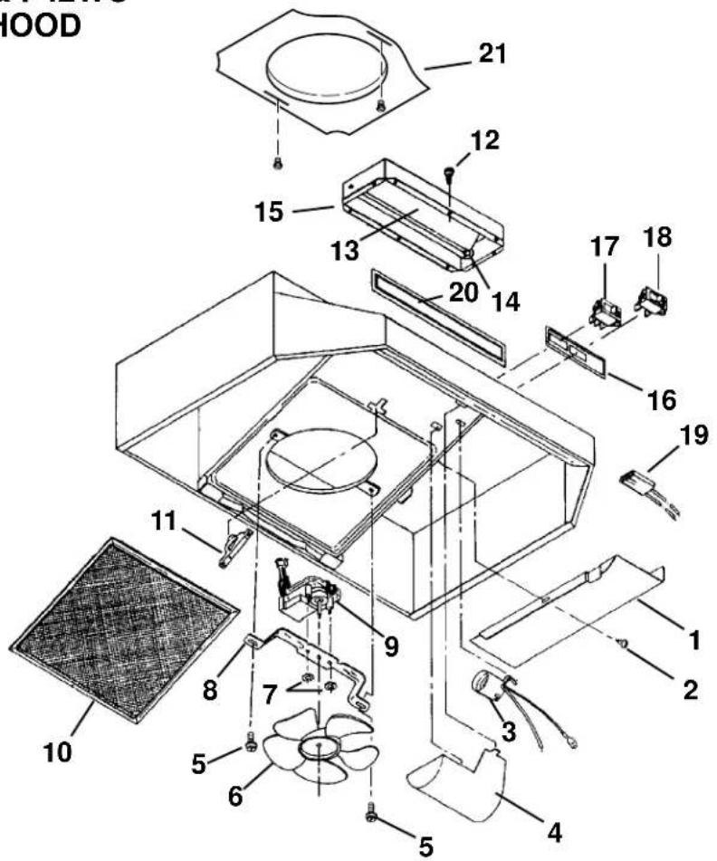
| KEY NO. DESCRIPTION |
| 1 Outlet Box Cover2 #8 x 3/8 Sheet Metal Screw*3 Bulb Holder with Wires4 Light Lens5 Screw/Nut Kit (Includes 2 - #10-16 x .500 screws and 2 - #10-16 sheet metal nuts)6 Fan Blade7 #6-32 Locking Nuts* (2 Required)8 Motor Mounting Bracket9 Motor Assembly (Includes Key Nos. 6, 7, and 8)10 Aluminum FilterNon-Ducted Filter (purchase separately)11 Filter Retainer12 #8B x 1/4 Hex Head Sheet Metal Screws* (2 Req)13 Damper Flap14 Damper Bushing15 Damper Assembly (Includes Key Nos. 13 and 14)16 Nameplate (Black)Nameplate (White)Nameplate (Biscuit)17 2-Speed Motor Switch (Black)2-Speed Motor Switch (White)2-Speed Motor Switch (Biscuit)18 Light Switch (Black)Light Switch (White)Light Switch (Biscuit)19 Motor Receptacle with Wires20 Louver Cover (Black)Louver Cover (White)Louver Cover (Biscuit)21 7" Round Duct Plate |
Order service parts by "KEY NO."
* Standard Hardware. May be purchased locally.
Major Appliance Warranty Information
Your appliance is covered by a one year limited warranty. For one year from your original date of purchase, Electrolux will pay all costs for repairing or replacing any parts of this appliance that prove to be defective in materials or workmanship when such appliance is installed, used, and maintained in accordance with the provided instructions.
Exclusions
This warranty does not cover the following:
- Products with original serial numbers that have been removed, altered or cannot be readily determined.
- Product that has been transferred from its original owner to another party or removed outside the USA or Canada.
- Rust on the interior or exterior of the unit.
- Products purchased "as-is" are not covered by this warranty.
- Food loss due to any refrigerator or freezer failures.
-
Products used in a commercial setting.
-
Service calls which do not involve malfunction or defects in materials or workmanship, or for appliances not in ordinary household use or used other than in accordance with the provided instructions.
-
Service calls to correct the installation of your appliance or to instruct you how to use your appliance.
-
Expenses for making the appliance accessible for servicing, such as removal of trim, cupboards, shelves, etc., which are not a part of the appliance when it is shipped from the factory.
-
Service calls to repair or replace appliance light bulbs, air filters, water filters, other consumables, or knobs, handles, or other cosmetic parts.
-
Surcharges including, but not limited to, any after hour, weekend, or holiday service calls, tolls, ferry trip charges, or mileage expense for service calls to remote areas, including the state of Alaska.
-
Damages to the finish of appliance or home incurred during installation, including but not limited to floors, cabinets, walls, etc.
-
Damages caused by: services performed by unauthorized service companies; use of parts other than genuine Electrolux parts or parts obtained from persons other than authorized service companies; or external causes such as abuse, misuse, inadequate power supply, accidents, fires, or acts of God.
DISCLAIMER OF IMPLIED WARRANTIES; LIMITATION OF REMEDIES
CUSTOMER'S SOLE AND EXCLUSIVE REMEDY UNDER THIS LIMITED WARRANTY SHALL BE PRODUCT REPAIR OR REPLACEMENT AS PROVIDED HEREIN. CLAIMS BASED ON IMPLIED WARRANTIES, INCLUDING WARRANTIES OF MERCHANTABILITY OR FITNESS FOR A PARTICULAR PURPOSE, ARE LIMITED TO ONE YEAR OR THE SHORTEST PERIOD ALLOWED BY LAW, BUT NOT LESS THAN ONE YEAR. ELECTROLUX SHALL NOT BE LIABLE FOR CONSEQUENTIAL OR INCIDENTAL DAMAGES SUCH AS PROPERTY DAMAGE AND INCIDENTAL EXPENSES RESULTING FROM ANY BREACH OF THIS WRITTEN LIMITED WARRANTY OR ANY IMPLIED WARRANTY. SOME STATES AND PROVINCES DO NOT ALLOW THE EXCLUSION OR LIMITATION OF INCIDENTAL OR CONSEQUENTIAL DAMAGES, OR LIMITATIONS ON THE DURATION OF IMPLIED WARRANTIES, SO THESE LIMITATIONS OR EXCLUSIONS MAY NOT APPLY TO YOU. THIS WRITTEN WARRANTY GIVES YOU SPECIFIC LEGAL RIGHTS. YOU MAY ALSO HAVE OTHER RIGHTS THAT VARY FROM STATE TO STATE.
If You Need Service
Keep your receipt, delivery slip, or some other appropriate payment record to establish the warranty period should service be required. If service is performed, it is in your best interest to obtain and keep all receipts. Service under this warranty must be obtained by contacting Electrolux at the addresses or phone numbers below.
This warranty only applies in the USA and Canada. In the USA, your appliance is warranted by Electrolux Major Appliances North America, a division of Electrolux Home Products, Inc. In Canada, your appliance is warranted by Electrolux Canada Corp. Electrolux authorizes no person to change or add to any obligations under this warranty. Obligations for service and parts under this warranty must be performed by Electrolux or an authorized service company. Product features or specifications as described or illustrated are subject to change without notice.
USA
1.800.944.9044
Electrolux Major Appliances
North America
P.O. Box 212378
Augusta, GA 30907
Canada
1.800.668.4606
Electrolux Canada Corp.
5855 Terry Fox Way
Mississauga, Ontario, Canada
L5V 3E4


- READ AND SAVE THESE INSTRUCTIONS
- For Non-ducted (Ductfree) Installation:
- For Ducted Installation:
- WARNING
- TO REDUCE THE RISK OF FIRE, ELECTRIC SHOCK, OR INJURY TO PERSONS, OBSERVE THE FOLLOWING:
- TO REDUCE THE RISK OF A RANGE TOP GREASE FIRE:
- TO REDUCE THE RISK OF INJURY TO PERSONS IN THE EVENT OF A RANGE TOP GREASE FIRE, OBSERVE THE FOLLOWING:\*
- CAUTION
- INSTALLER: Leave This Manual With the Homeowner.
- HOMEOWNER: Use and Care Information on Page 5.
- TOOLS AND MATERIALS REQUIRED
- TOOLS
- For Ducted Installations ONLY:
- MATERIALS
- PLANNING DUCTWORK INSTALLATION
- PREPARING THE RANGE HOOD
- For Ductfree Installations Only:
- NOTE
- DUCTED INSTALLATION ONLY
- PREPARING THE INSTALLATION LOCATION
- INSTALLING THE DUCTWORK
- WALL CAPS (FIG. 9)
- ROOF CAPS
- INSTALLING THE RANGE HOOD
- USE AND CARE
- SWITCHES
- CLEANING
- FILTER REMOVAL
- LIGHT BULB REPLACEMENT
- FAN ASSEMBLY REMOVAL
- SERVICE PARTS
- Major Appliance Warranty Information
- Exclusions
- This warranty does not cover the following:
- DISCLAIMER OF IMPLIED WARRANTIES; LIMITATION OF REMEDIES
- If You Need Service
- USA
- 1.800.944.9044
- Canada
- 1.800.668.4606
Brand : FRIGIDAIRE
Model : F30WC19EC
Category : Home Appliance