
WISE-1510 - IoT module Advantech - Free user manual and instructions
Find the device manual for free WISE-1510 Advantech in PDF.

| Type | IoT Wireless Sensor Module |
| Brand | Advantech |
| Model | WISE-1510 |
| Dimensions | 70 x 50 x 25 mm |
| Weight | 45 g |
| Power Supply | 5V DC via USB or terminal block |
| Current Consumption | 100 mA typical |
| Wireless Protocol | LoRaWAN (EU868 or US915) |
| Frequency Band | 868 MHz (EU) / 915 MHz (US) |
| Max Transmission Power | 14 dBm |
| Range | Up to 10 km (line of sight) |
| Sensor Interface | Digital I/O, Analog Input, RS-485 |
| Processor | ARM Cortex-M4 |
| Memory | 512 KB Flash, 128 KB RAM |
| Operating Temperature | -20°C to 60°C |
| Enclosure | Industrial plastic |
| IP Rating | IP30 |
| Mounting | DIN rail or wall mount |
| LED Indicators | Power, Status, Link |
| Functions | Data logging, remote monitoring, alarm |
| Maintenance | No regular maintenance needed |
| Safety | Use in dry environment, avoid water immersion |
| Repairability | Not user-serviceable, contact support |
Frequently Asked Questions - WISE-1510 Advantech
User questions about WISE-1510 Advantech
0 question about this device. Answer the ones you know or ask your own.
Ask a new question about this device
Download the instructions for your IoT module in PDF format for free! Find your manual WISE-1510 - Advantech and take your electronic device back in hand. On this page are published all the documents necessary for the use of your device. WISE-1510 by Advantech.
USER MANUAL WISE-1510 Advantech
natural_image
Illustration of four electronic circuit boards with white outlines on a purple background (no text or symbols)WISE-1510
M2.COM LoRa IoT Node
Copyright
The documentation and the software included with this product are copyrighted 2019 by Advantech Co., Ltd. All rights are reserved. Advantech Co., Ltd. reserves the right to make improvements in the products described in this manual at any time without notice. No part of this manual may be reproduced, copied, translated or transmitted in any form or by any means without the prior written permission of Advantech Co., Ltd. Information provided in this manual is intended to be accurate and reliable. However, Advantech Co., Ltd. assumes no responsibility for its use, nor for any infringements of the rights of third parties, which may result from its use.
Acknowledgements
ARM is trademarks of ARM Corporation.
Freescale is trademarks of Freescale Corporation.
Microsoft Windows are registered trademarks of Microsoft Corp.
All other product names or trademarks are properties of their respective owners.
Product Warranty (2 years)
Advantech warrants to you, the original purchaser, that each of its products will be free from defects in materials and workmanship for two years from the date of purchase.
This warranty does not apply to any products which have been repaired or altered by persons other than repair personnel authorized by Advantech, or which have been subject to misuse, abuse, accident or improper installation. Advantech assumes no liability under the terms of this warranty as a consequence of such events.
Because of Advantech's high quality-control standards and rigorous testing, most of our customers never need to use our repair service. If an Advantech product is defective, it will be repaired or replaced at no charge during the warranty period. For out-of-warranty repairs, you will be billed according to the cost of replacement materials, service time and freight. Please consult your dealer for more details.
If you think you have a defective product, follow these steps:
-
Collect all the information about the problem encountered. (For example, CPU speed, Advantech products used, other hardware and software used, etc.) Note anything abnormal and list any onscreen messages you get when the problem occurs.
-
Call your dealer and describe the problem. Please have your manual, product, and any helpful information readily available.
-
If your product is diagnosed as defective, obtain an RMA (return merchandise authorization) number from your dealer. This allows us to process your return more quickly.
-
Carefully pack the defective product, a fully-completed Repair and Replacement Order Card and a photocopy proof of purchase date (such as your sales receipt) in a shippable container. A product returned without proof of the purchase date is not eligible for warranty service.
-
Write the RMA number visibly on the outside of the package and ship it prepaid to your dealer.
Part No. 2006E15100 Edition 1
Printed in China March 2019
Declaration of Conformity
FCC Class B
Note: This equipment has been tested and found to comply with the limits for a Class B digital device, pursuant to part 15 of the FCC Rules. These limits are designed to provide reasonable protection against harmful interference in a residential installation.
This equipment generates, uses and can radiate radio frequency energy and, if not installed and used in accordance with the instructions, may cause harmful interference to radio communications. However, there is no guarantee that interference will not occur in a particular installation. If this equipment does cause harmful interference to radio or television reception, which can be determined by turning the equipment off and on, the user is encouraged to try to correct the interference by one or more of the following measures:
■ Reorient or relocate the receiving antenna.
■ Increase the separation between the equipment and receiver.
■ Connect the equipment into an outlet on a circuit different from that to which the receiver is connected.
- Consult the dealer or an experienced radio/TV technician for help.
FCC Caution
Any changes or modifications not expressly approved by the party responsible for compliance could void the user's authority to operate this equipment.
This device complies with Part 15 of the FCC Rules. Operation is subject to the following two conditions: (1) This device may not cause harmful interference, and (2) this device must accept any interference received, including interference that may cause undesired operation.
IMPORTANT NOTE
FCC Radiation Exposure Statement:
This equipment complies with FCC radiation exposure limits set forth for an uncontrolled environment. This equipment should be installed and operated with minimum distance 20cm between the radiator & your body.
This module is intended for OEM integrator. The OEM integrator is responsible for the compliance to all the rules that apply to the product into which this certified RF module is integrated.
Additional testing and certification may be necessary when multiple modules are used.
USERS MANUAL OF THE END PRODUCT:
In the users manual of the end product, the end user has to be informed to keep at least 20cm separation with the antenna while this end product is installed and operated. The end user has to be informed that the FCC radio-frequency exposure guidelines for an uncontrolled environment can be satisfied.
The end user has to also be informed that any changes or modifications not expressly approved by the manufacturer could void the user's authority to operate this equipment.
If the labelling area is small than the palm of the hand, then additional FCC part 15.19 statement is required to be available in the users manual: This device complies with
Part 15 of FCC rules. Operation is subject to the following two conditions: (1) this device may not cause harmful interference and (2) this device must accept any interference received, including interference that may cause undesired operation.
LABEL OF THE END PRODUCT:
The final end product must be labeled in a visible area with the following "Contains TX FCC ID: M82-WISE1510".
If the labelling area is larger than the palm of the hand, then the following FCC part 15.19 statement has to also be available on the label: This device complies with Part 15 of FCC rules. Operation is subject to the following two conditions: (1) this device may not cause harmful interference and (2) this device must accept any interference received, including interference that may cause undesired operation.
IC
This radio transmitter has been approved by Industry Canada to operate with the antenna types listed below with the maximum permissible gain indicated. Antenna types not included in this list, having a gain greater than the maximum gain indicated for that type, are strictly prohibited for use with this device.
This device complies with Industry Canada license-exempt RSS standard(s). Operation is subject to the following two conditions: (1) this device may not cause interference, and (2) this device must accept any interference, including interference that may cause undesired operation of the device.
This radio transmitter (9404A-WISE1510) has been approved by Industry Canada to operate with the antenna types listed below with the maximum permissible gain indicated. Antenna types not included in this list, having a gain greater than the maximum gain indicated for that type, are strictly prohibited for use with this device.
Part No. MPN Description
1750008625-01 TH-915i Dipole Ant. SUB-1G 1.8dBi SMA/M BLK 902-928 IPX6
IMPORTANT NOTE
IC Radiation Exposure Statement:
This equipment complies with IC RSS-102 radiation exposure limits set forth for an uncontrolled environment. This equipment should be installed and operated with minimum distance 20cm between the radiator & your body.
This module is intended for OEM integrator. The OEM integrator is responsible for the compliance to all the rules that apply to the product into which this certified RF module is integrated.
Additional testing and certification may be necessary when multiple modules are used.
Any changes or modifications not expressly approved by the manufacturer could void the user's authority to operate this equipment.
USERS MANUAL OF THE END PRODUCT:
In the users manual of the end product, the end user has to be informed to keep at least 20cm separation with the antenna while this end product is installed and operated. The end user has to be informed that the IC radio-frequency exposure guidelines for an uncontrolled environment can be satisfied.
The end user has to also be informed that any changes or modifications not expressly approved by the manufacturer could void the user's authority to operate this equipment. Operation is subject to the following two conditions: (1) this device may not cause harmful interference and (2) this device must accept any interference received, including interference that may cause undesired operation.
LABEL OF THE END PRODUCT:
The final end product must be labeled in a visible area with the following "Contains IC: 9404A-WISE1510".
The Host Model Number (HMN) must be indicated at any location on the exterior of the end product or product packaging or product literature which shall be available with the end product or online.
低功率電波輻射性電機管理辦法
Before setting up the system, check that the items listed below are included and in good condition. If any item does not accord with the table, please contact your dealer immediately.
1 x WISE-1510
■ 1 x Screw for WISE-1510
■ 1 x China RoHs Notice
Optional Accessories
| Part No. Description |
| 1750008598-01 Sub G antenna Dipole L=195mm, 1dBi 902~928 MHz |
| 1750008599-01 Sub G antenna Dipole L=195mm, 1dBi 863~870 MHz |
| 1750008569-01 Antenna Cable SMA to MHF4 L=300mm |
| 1700015038 FPC Cable 10P-0.5mm 7.9cm for DCU2.0 |
| 9696WED200E ASS'Y WISE-ED20 A101-1 M2.COM Daughter |
| 1931000590 Screw M2.5x5L F/S D=5.3 H=0.8 (1+) ST Ni |
| 1700023619-01 A cable USB-A 4P(M)/micro USB 5P(M) 1m ADAM-T212 |
| 1700025876-01 M cable USB-A 4P(M)/Plug-in 2P-5.0 90CM |
| XRISC-ADP-10HW-AG ADP A/D 100-240V 10W 5V WM |
| 193A231540 POST F=M3*6L M=M3*6L D=5 d=2.88 B=5 H=15 Cu |
Development Board
| Part No. Description |
| 9696150000E ASS'Y WISE-DB1500 A101-1 M2.COM CARRIER |
Ordering Information
| Part No. WISE-1510WMB-SDA1N |
| Frequency Band 902-928MHz for North America (LoRa) |
| Part No. WISE-1510WMB-SDA1E |
| Frequency Band 863-870MHz for Europe (LoRa) |
| Part No. WISE-1510WMB-SDA1J |
| Frequency Band 902~928MHz for Japan (LoRa) |
| Part No. WISE-1510WMB-SDA1C |
| Frequency Band 470~510MHz for China (LoRa) |
| Part No. WISE-1510WMB-SDA1T |
| Frequency Band 920~925MHz for Taiwan (LoRa) |
Safety Instructions
- Read these safety instructions carefully.
- Keep this User Manual for later reference.
- Disconnect this equipment from any AC outlet before cleaning. Use a damp cloth. Do not use liquid or spray detergents for cleaning.
-
For plug-in equipment, the power outlet socket must be located near the equipment and must be easily accessible.
-
Keep this equipment away from humidity.
-
Put this equipment on a reliable surface during installation. Dropping it or letting it fall may cause damage.
-
The openings on the enclosure are for air convection. Protect the equipment from overheating. DO NOT COVER THE OPENINGS.
-
Make sure the voltage of the power source is correct before connecting the equipment to the power outlet.
-
Position the power cord so that people cannot step on it. Do not place anything over the power cord.
-
All cautions and warnings on the equipment should be noted.
-
If the equipment is not used for a long time, disconnect it from the power source to avoid damage by transient overvoltage.
-
Never pour any liquid into an opening. This may cause fire or electrical shock.
-
Never open the equipment. For safety reasons, the equipment should be opened only by qualified service personnel.
-
If one of the following situations arises, get the equipment checked by service personnel:
■ The power cord or plug is damaged.
■ Liquid has penetrated into the equipment.
■ The equipment has been exposed to moisture.
The equipment does not work well, or you cannot get it to work according to the user's manual.
■ The equipment has been dropped and damaged.
■ The equipment has obvious signs of breakage.
DISCLAIMER: This set of instructions is given according to IEC 704-1. Advantech disclaims all responsibility for the accuracy of any statements contained herein.
Contents
Chapter 1 Product Overview....1
1.1 Introduction 2
1.1.1 Product Features 2
Chapter 2 H/W Installation....5
2.1 Board Connector....6
Figure 2.1 Card Edge Bevel 6
Figure 2.2 Card Edge Outline-Topside....7
Figure 2.3 Card Edge Outline-Backside 7
2.2 Module Outline....8
Figure 2.4 Type A 2230 8
2.3 Connector Specifications 9
2.3.1 Top Side Connector Physical Dimensions....9
2.3.2 Carrier Board Connection Length 10
Figure 2.5 Carrier Board Connection Length.... 10
2.3.3 Carrier Board Connector Height 10
Figure 2.6 H3.2-D3 10
2.4 WISE-1510 Pin-Out Map.... 11
Figure 2.7 M.2 Connector.... 12
2.5 Quick Starter of WISE-1510.... 12
2.5.1 LoRaWAN and Proprietary LoRa (WISELink 1.0 and WISELink 2.0).... 13
2.5.2 Class A and Class C.... 14
2.5.3 Data rate vs Distance.... 15
Figure 2.8 Data rate and Distance.... 15
Chapter 3 How to choose your solution on WISELink....17
3.1 Parking Lot: WISELink 1.0 with Class A, ABP mode 18
Figure 3.1 Work Flow on Parking Lot solution.... 18
3.2 Aquaculture: WISELink 1.0 with Class C, ABP mode 19
3.3 Environment Monitoring: WISELink 2.0 with Class A, OTAA mode..... 20
Figure 3.2 Work Flow on Environment Monitoring solution ..... 20
3.4 Factory: WISELink 2.0 with Class C, OTAA mode (Default SDK Setting) .. 21
Figure 3.3 Work Flow on Factory solution 21
Chapter 4 Development Environment Setup....23
4.1 File Structure.... 24
4.1.1 Mbed OS.... 24
4.1.2 WISELink 24
4.2 OS Version.... 24
4.3 Environment Setup Procedure.... 24
4.3.1 Installation.... 25
4.3.2 Configuration.... 26
4.3.3 Compilation.... 26
4.4 Firmware Upgrade 27
Chapter 5 Binding Process between WISE-1510 and WISE-3610 .... 33
5.1 CLI Command Description.... 34
5.2 WISELink 1.0 with Class A, ABP mode 35
5.2.1 Settings on WISE-1510 35
5.2.2 Settings on WISE-3610 35
5.3 WISELink 1.0 with Class C, ABP mode 38
5.3.1 Settings on WISE-1510 38
5.3.2 Settings on WISE-3610 39
5.4 WISELink 2.0 with Class A, OTAA mode.... 42
5.4.1 Settings on WISE-1510 42
5.4.2 Settings on WISE-3610 43
5.5 WISELink 2.0 with Class C, OTAA mode 47
5.5.1 Settings on WISE-1510 47
5.5.2 Settings on WISE-3610 47
Appendix A Application Interface Description (WISELink Application) 51
A.1 Application Interface Description (WISELink Application).... 52
Appendix B Application Sample Code Flow ..... 53
B.1 Application Sample Code Flow 54
Appendix C Sensor Data Format.... 55
C.1 Sensor Data Format.... 56
Chapter 1
Product Overview
This chapter gives background information on the WISE-1510.
Sections include:
Introduction
Specifications
1.1 Introduction
WISE-1510 is a wireless module integrated with ARM Cortex-M4 Processor and LoRa / LoRaWAN connectivity. This technology is the best solution for Low-Power Wide-Area Network (LPWAN) Applications. LoRaWAN is defined to optimize the power consumption and wide range. Your sensors or applications with low data rate requirement can be achieved years battery lifetime and kilometers long distance connection. Advantech WISE-1510 also provides multi-interfaces for sensor and I/O control. With ARM mbed embedded microprocessor operating system and add-on software stacks, it's convenient to build the application software or sensor algorithm over mbed OS. Data can be quickly and easily acquired and transformed into a different format to communicate with WISE-PaaS or other cloud services. Developer can build their application backbone faster and focus on their applications, value-added services.
The main features of WISE-1510 are:
■ ARM Cortex-M4 Core Processor
■ Built-in LoRa / LoRaWAN connectivity
■ Great for Low Power Wide Range application
■ Rich interfaces for sensor and I/O control
■ Support mbed OS 5.8
■ Support wide temperature -40 \~ 85 °C
1.1.1 Product Features
| Processor System MCU | ARM Cortex-M4 Core Processor 80MHz STM - STM32L443RC | |
| Memory RAM 64KB | ||
| Flash 256KB | ||
| Form Factor M2.COM Type A 2230 | ||
| Spec. Standard M2 COM Technical SPEC_v1.1 | ||
| Wireless Network | Standard LoRa Proprietary (WISE-Link) / LoRaWAN | |
| Frequency Band | 863-870MHz for Europe902-928MHz for North America and Japan470~510MHz for China | |
| Channels Spreading Factor: 7 ~ 12 | ||
| Topology Star network | ||
| Transmit Power | Up to +18dBm | |
| Receiver Sensitivity | Up to -136dBm at SF = 12 / 125KHz | |
| RF Data Rate | 50 kbps at FSK mode EU868(Based on LoRaWAN spec 1R0 version)21.9 kbps at SF7 mode US915(Based on LoRaWAN spec 1R0 version) | |
| Function | End node | |
| Antenna connector | MHF4 connector | |
| I/O | UART 1 (4-wire, support RTC/CTS) | |
| I2C 1 | ||
| GPIO 8 | ||
| PWM 1 | ||
| SPI 1 | ||
| ADC 4 | ||
| USB 1 (device only) | ||
| Programming / Debug Port | 1 via WISE-ED20 (CN1) | |
| Power 3.3V | ||
| Environment | Operational Temperature -40 ~ 85°C | |
| Operating Humidity 5% ~ 95% Relative Humidity, non-condensing | ||
| Physical Characteristics | Dimensions (WxD) 22 x 30 mm | |
| OS | mbed 5.8 | |
Note! Frequency Band can be configurable for Japan or Korea by request.

Chapter 2
H/W Installation
This chapter gives mechanical and connector information on the WISE-1510
Sections include:
Board Connector
Module Outline
Connector Specifications
WISE-1510 Pin-Out Map
■ Quick Starter of WISE-1510
2.1 Board Connector
M2.COM Type A Module
■ Module size: 22 mm x 30 mm
■ PCB thickness: 0.8 mm ± 10%
■ Pin count: 75 pins
■ Module input voltage: 3.3V DC-in
■ Connector mating force: 30N Maximum
■ Connector current rating: 0.5A / Power contact
- Connector operation temperature range: -45 °C to +85 °C

Figure 2.1 Card Edge Bevel
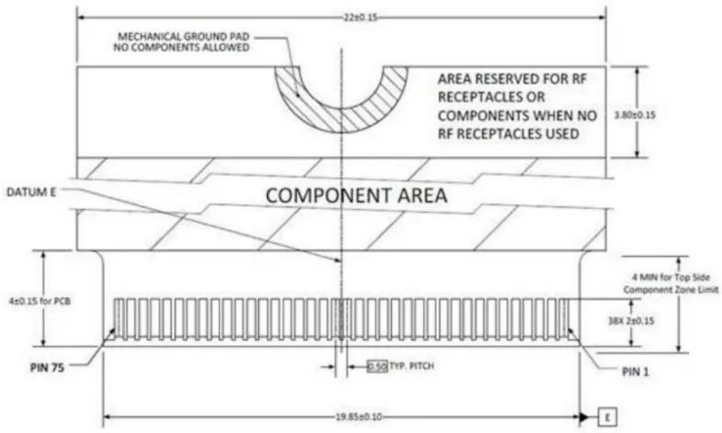
Figure 2.2 Card Edge Outline-Topside

Figure 2.3 Card Edge Outline-Backside
Reference from PCI Express M.2 Specification Rev 1.0 (Nov 1, 2013) Section 2.3.5 Card PCB Details
2.2 Module Outline
The mechanical dimension information of M2.COM form factor follows the Type A 2230 module size: 22 x 30 mm. Both module types use a 75-position host interface connector and have room to support up to four RF connectors in the upper section.
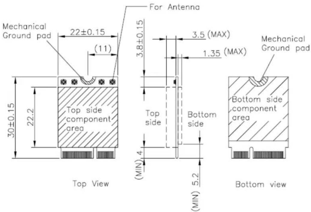
Figure 2.4 Type A 2230
2.3 Connector Specifications
2.3.1 Top Side Connector Physical Dimensions
The top-side scheme has two connectors that share a common footprint but have different stack-up requirements.
■ Length - 22 mm maximum including land pattern
■ Width - 9.1 mm maximum including land pattern
![9.10 MAX INCLUDING LAND PATTERN [1.75] MODULE SEATING PLANE TO ALIGNMENT POST 22 MAX INCLUDING LAND PATTERN 20.15±0.05 4.30 MAX INCLUDING LAND PATTERN AL](/content/2026/06/1213079/images/93199880662ee85258a6dfca1f144256b7feafcd6b3ac31dc0f44cd4dbaf4470.jpg)
| Height | A (MAX) | B (MAX) |
| H2.3 | 2.25 | 0.41 |
| H2.5 | 2.45 | 0.61 |
| H2.8 | 2.75 | 0.89 |
| H3.2 | 3.20 | 1.54 |
| H4.2 | 4.20 | 2.54 |
ALL DIMENSIONS mm

2.3.2 Carrier Board Connection Length
The carrier board connector of M2.COM follows the Type 2230 M.2 module connector:
The additional increase in length is 7.05mm maximum for top-side connector to the module length.
- The retention screw adds 2.75 mm maximum.
- The maximum extension, including land pattern, beyond the module leading edge is 4.3 mm.
■ M2.COM module lengths are 30 mm and 42 mm.
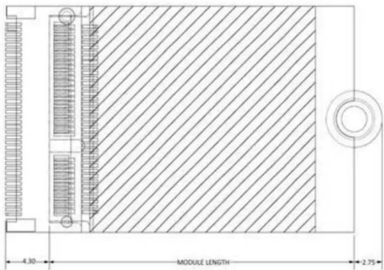
Figure 2.5 Carrier Board Connection Length
Reference from PCI Express M.2 Specification, Revision 1.0, November 1, 2013
2.3.3 Carrier Board Connector Height
The dimensions of M2.COM form factor follow the Type A 2230 -D3 M.2 module size. Hence, the carrier board connectors must choose H3.2-D3 or H4.2-D5 connector as in the following diagrams.

Figure 2.6 H3.2-D3
Reference from PCI Express M.2 Specification, Revision 1.0, November 1, 2013
2.4 WISE-1510 Pin-Out Map
| PIN | M2.COM Signal name | STM32L443RCI6 MCU Pin Name | M2.COM Signal name | PIN | |||
| 1 | G | N | D | G | N | D | |
| 3 | U | S | B | _ | D | P | P |
| 5 | U | S | B | _ | D | M | P |
| 7 | G | N | D | G | N | D | |
| 9 | N | . | C | . | N | . | |
| 11 | N.C. | N.C. | 12 | ||||
| 13 | N.C. | N.C. | 14 | ||||
| 15 | N.C. | PC6 | CB_RESET_OUT# | 16 | |||
| 17 | N.C. | GND | GND | 18 | |||
| 19 | N.C. | PC9 | CB_PWR_ON | 20 | |||
| 21 | N.C. | PC4 | UART TX (O) | 22 | |||
| 23 | N.C. | Connector Key | |||||
| Connector Key | Connector Key | ||||||
| Connector Key | Connector Key | ||||||
| Connector Key | Connector Key | ||||||
| Connector Key | PB11 | UART RX (I) | 32 | ||||
| 33 | GND | GND | PB1 | UART RTS (O) | 34 | ||
| 35 | N.C. | PB13 | UART CTS (I) | 36 | |||
| 37 | N.C. | PA8 | GPIO0 | 38 | |||
| 39 | GND | GND | PC8 | GPIO1 | 40 | ||
| 41 | PWM0 | PA5 | PC7 | GPIO2 | 42 | ||
| 43 | N.C. | PC5 | GPIO3 | 44 | |||
| 45 | GND | GND | PB0 | GPIO4 | 46 | ||
| 47 | ADC0 | PA7 | PA3 | GPIO5 | 48 | ||
| 49 | N.C. | PA2 | GPIO6 | 50 | |||
| 51 | GND | GND | PB6 | GPIO7 | 52 | ||
| 53 | ADC2 | PA6 | N.C. | 54 | |||
| 55 | ADC3 | PA4 | PC2 | W_DISABLE# | 56 | ||
| 57 | GND | GND | PC1 | I2C_DATA | 58 | ||
| 59 | ADC4 | PA0 | PC0 | I2C_CLK | 60 | ||
| 61 | N.C. | PB15 | SPI_MOSI | 62 | |||
| 63 | GND | GND | PB14 | SPI_MISO | 64 | ||
| 65 | VDD_RTC | VBAT(3.3V) | PB10 | SPI_CLK | 66 | ||
| 67 | Backup# | PA1 | PB12 | SPI_CS0# | 68 | ||
| 69 | GND | GND | PB9 | SPI_CS1# | 70 | ||
| 71 | RESET_IN# | NRST | 3.3V | VCC | 72 | ||
| 73 | Wake# | PC3 | 3.3V | VCC | 74 | ||
| 75 | GND | GND | |||||
. 1 1 .
1
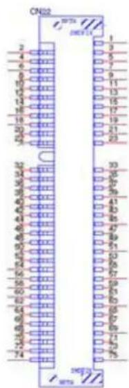
Figure 2.7 M.2 Connector
2.5 Quick Starter of WISE-1510
WISE-1510 is a wireless module integrated with ARM Cortex-M4 Processor and LoRaWAN/Proprietary LoRa (WISELink 1.0 and WISELink 2.0) connectivity. In this document, we will guide you to build your own Low-Power Wide-Area Network (LPWAN) kit solution as fast as you think.
In this chapter, we will guide you to know the function protocol and limitation about LoRa solution. First, we will let you know the difference between LoRaWAN and our Proprietary LoRa(WISELink 1.0 and WISELink 2.0) solution, we will show you what's our advantage compare with LoRaWAN. Second, we will descript the difference between Class A and Class C. Third, we will descript the correspondence between data rate and signal distance. Forth, we will show you 4 cases to make you fully understand our Private LoRa (WISELink 1.0 and WISELink 2.0) solution.
Basing the knowledge in this chapter, you can quickly select a solution to fulfill your requirement and accelerate the development schedule.
2.5.1 LoRaWAN and Proprietary LoRa (WISELink 1.0 and WISELink 2.0)
We compare with LoRaWAN and our proprietary LoRa solution (WISELink 1.0 and WISELink 2.0). Please check the following table for more details.
| LoRa WAN 1.0.x WISELink 1.0 WISELink 2.0 | ||||
| Network Service | Join | Nodes initiate JOIN blindly even GW is out of range, which causes interference to other irrelevant GWs and their nodes | Nodes initiate JOIN blindly even GW is out of range, which causes interference to other irrelevant GWs and their nodes | 1. NetID is broadcast by GW.2. Nodes only initial the JOIN procedure after catching NetID. |
| Roaming | NetID is only known after JOIN, It is left for users to define how to use NetID to achieve Roaming | Roaming is not supported | NetID identified by Nodes among clustered GWs. | |
| Multi cast | Multicast is not defined | Multicast is not defined | Support1. GW can do multicast by assigning the packet of a multicast network address2. Encrypt it using a multicast key. | |
| Scheduling | Multi tasking | Aloha: Sending packets by node control may cause collision between packets | Aloha: Sending packets by node control may cause collision between packets | TDMA:GW send SPS through beacon and the node's transmission time is dependent on it. |
| QoS | LoRaWAN defines confirmed data, which allows either GW or Nodes to retransmit data if it is not Acked | WISE-Link 1.0 defines confirmed data, which allows Nodes to retransmit data if it is not Acked | Guaranteed to send data without collision periodically by SPS cycle. | |
| Security | Key lifetime | Once Nodes completed JOIN, the life-time of session keys are permanent | Nodes are requested to do periodical JOIN, thus session keys can be refreshed on each JOIN | Nodes are requested to do periodical JOIN, thus session keys can be refreshed on each JOIN |
| Multi-cast key | Undefined Multicast Key | Undefined Multicast Key | Two multicast keys are generated on each JOIN, and switch on half of max sequence number period | |
| Radio Interference Management | Channel Assignment | Static Channel Assignment | Static Channel Assignment | GW use sniffer to find a non-used or least used channel |
| Power Control | Unclear Power Control | Not support | GW can control transmission power. | |
| Service Model | Net-work | LoRaWAN is built into eco-system, and the service is provided by operators. The operator will provide an interface (REST APIs, etc) for the fulfillment of end-to-end device and data management between their clouds and nodes. The business model all depends on operators' policy | WISE-Link comes with Embedded Network Manager (ENM). ENM communicates with the embedded MQTT server of GW for fulfillment of device and data management. Users' clouds can communicate with ENM also via MQTT, and thus achieve Zero-Touch, Over-the-air firmware upgrade, end-to-end device and data management. It doesn't involve with operators. | WISE-Link comes with Embedded Network Manager (ENM). ENM communicates with the embedded MQTT server of GW for fulfillment of device and data management. Users' clouds can communicate with ENM also via MQTT, and thus achieve Zero-Touch, Over-the-air firmware upgrade, end-to-end device and data management. It doesn't involve with operators. |
| Communi-cation with Gateway | Uplink and Downlink Uplink and Downlink Uplink and Downlink | |||
| Scenario Node is the Host Node is the Host Gateway is the Host | ||||
| Coverage | 1^st | 1^st | 2^nd | |
| Price | 1^st | 2^nd | 2^nd | |
2.5.2 Class A and Class C
Based on LoRa MAC layer operation, there are three classes of end devices in LoRa network. Our proprietary LoRa solution (WISELink 1.0 and WISELink 2.0) supports Class A and Class C. These two different class devices are designed to address different needs for the wide range of applications.
| WISELink 1.0 Class A Class C | ||
| Power Saving O | X | |
| Bidirectional communications O | O | |
| Unicast messages O | O | |
| Multicast messages | O | O |
| Data Uplink | End-device initiates com-munication | End-device initiates com-munication |
| Data Downlink | End-device receives data via ACK | End-device is constantly receive |
| WISELink 2.0 | Class A | Class C |
| Power Saving | O | X |
| Bidirectional communications | O | O |
| Unicast messages | O | O |
| Multicast messages | O | O |
| Data Uplink | End-device initiates communication via SPS cycle | End-device initiates communication via SPS cycle |
| Data Downlink | End-device receives data via SPS cycle | End-device receives data via SPS cycle |
Detail comparison as follow
Power Saving:
WISELink 2.0 Class A > WISELink 1.0 Class A > WISELink 1.0 Class C = WISELink 2.0 Class C
Wireless Coverage:
WISELink 1.0 Class C = WISELink 1.0 Class A > WISELink 2.0 Class C = WISELink 2.0 Class A
2.5.3 Data rate vs Distance
LoRa has many parameters. The one which the research is focusing on is the Spreading Factor. The Spreading Factor is a set of parameters that specify transmit power, subfrequency and air time. LoRa defines spreading factors numbered from 6 to 12. The lower is the spreading factor, the higher is the throughput, and the lower is the distance covered. Also, lower spreading factor means lower power consumption.
At SF7, the distance is minimal, and the throughput is high. At SF12 (or SF11, depending on bandwidth - at 125 kHz, SF11 and SF12 are swapped), the distance is the max distance covered by LoRa standard, and the data rate is the lowest.
The spreading factor also changes the Air Time (or Time On Air). The Air Time is minimal at SF7. At each higher spreading factor, the value is nearly doubled.
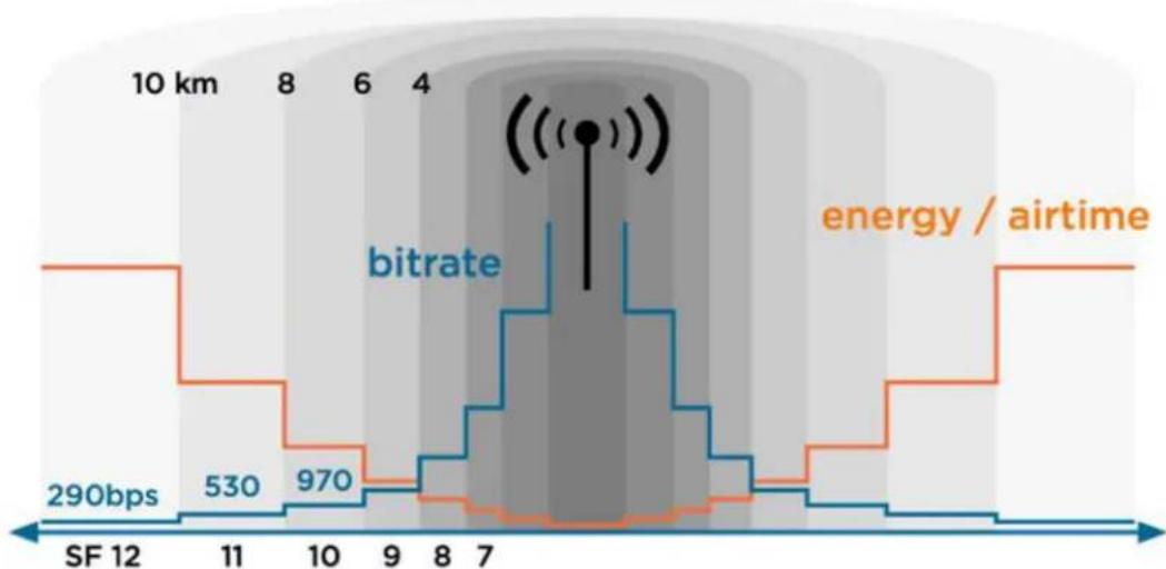
Figure 2.8 Data rate and Distance
Spreading factors were assigned manually since the difference of LoRa regulation between countries and countries.
Chapter 3
How to choose your solution on WISELink
WISELink provides a variety of communication applications. In this section, we will guide you to understand the differences between WISELink 1.0 and WISELink 2.0 by using 4 different IoT projects, which are Parking Lot, Aquaculture, Environment Monitoring and Factory.
3.1 Parking Lot: WISELink 1.0 with Class A, ABP mode
This application has been massive implemented in Parking lot IoT solutions. The basic function requirement is in the following table.
Function Requirement
Sleep Mode (Power Saving Mode)
Clock Setting
MCUs communication via AT Command
Confirm data needed
Low Data Rate
Long Range Wireless Coverage
The flow chart as follow.
Figure 3.1 Work Flow on Parking Lot solution
- Node handshakes and binding with Gateway.
Note: This procedure only happens in the first binding process between node and gateway. - Node change state from LoRa Join into Sleep Mode
Note: The sleep cycle is depending on the define in the SDK of 1510. - Magnetic Sensor is be triggered.
- Host MCU will wake up the node via hardware wake up pin.
- Host MCU will deliver the sensor data to the node.
- Node will package the data and report to gateway. After that, node will change state and back to Sleep Mode (Step2).
3.2 Aquaculture: WISELink 1.0 with Class C, ABP mode
This application has been massive implemented in Aquaculture IoT solutions. The basic function requirement is in the following table.
| Function Requirement |
| MCUs communication via AT Command |
| Confirm data needed |
| High Data Rate (Multi-sensors) |
| Long Range Wireless Coverage |
| Downlink control needed |
The flow chart as follow.

flowchart
graph TD
    A["sensor"] -->|4->2 Get sensor data| B["node"]
    B -->|1 LoRa Join| C["Gateway"]
    C -->|3 Report data| B
    B -->|4 Wait A report interval time| B
    C -->|Downlink data (anytime)| B
- Node handshakes and binding with Gateway.
Note: This procedure only happens in the first binding process between node and gateway.
- Node changes state to get the sensor data from sensors.
- Node will package the data and report to gateway. After that, node will scheduling wait for next time report (Step4). In the meanwhile, node can receive a downlink data from gateway anytime.
Note: The scheduling waiting time is depending on the define in the SDK of 1510.
3.3 Environment Monitoring: WISELink 2.0 with Class A, OTAA mode
This application has been massive implemented in Environment Monitoring IoT solutions. The basic function requirement is in the following table.
| Function Requirement |
| Sleep Mode (Power Saving Mode) |
| Clock Setting |
| Confirm data needed |
| Low Data Rate |
| Long Range Wireless Coverage |
| Scheduling Monitoring |
| Downlink control needed |
The flow chart as follow.

flowchart
graph TD
    A["sensor"] --> B["node"]
    B --> C["Gateway"]
    C --> D["LoRa Join"]
    D --> E["node"]
    E --> F["zzZZ.."]
    F --> G["Set alarm clock (SPS cycle)"]
    G --> H["5 Wake up (go off)"]
    H --> I["Get sensor data"]
    I --> J["3 Report data (beacon)"]
    I --> K["3.1 Downlink data (beacon of each SPS cycle)"]
    J --> L["1 Frame = 1 TTI = 2.4sec = max 48 slots = n subframes"]
    K --> L
    L --> M["3 Report data (beacon)"]
    L --> N["3.1 Downlink data (beacon of each SPS cycle)"]
Figure 3.2 Work Flow on Environment Monitoring solution
- Node handshakes and binding with Gateway.
Note: This procedure only happens on the Join Event (rejoin) and the rejoin cycle is defined on gateway.
-
Node changes state to get the sensor data from sensors.
-
Node packages the data and wait for suitable time and report the data to gateway. After report the data, node can receive a downlink data via gateway's beacon (Step 3.1) but normally this function won't be use in Environment Monitoring IoT solutions.
Note: Node will know when can report the data to gateway via the message which is hiding in the beacon.
- Node changes state to Sleep Mode
Note: The sleep cycle is depending on the SPS cycle settings on gateway..
- Times up to wake up and directly go to step 2 when node doesn't need to rejoin the gateway.
3.4 Factory: WISELink 2.0 with Class C, OTAA mode (Default SDK Setting)
This application has been massive implemented in Factory IoT solutions. The basic function requirement is in the following table.
| Function Requirement |
| Sleep Mode (Power Saving Mode) |
| Clock Setting |
| Confirm data needed |
| Low Data Rate |
| Long Range Wireless Coverage |
| Scheduling Monitoring |
| Downlink control needed |
| The flow chart as follow. |

flowchart
graph TD
    A["sensor"] -->|4->2 Get sensor data| B["node"]
    B -->|1 Report data (beacon)| C["Gateway"]
    C -->|3 Downlink data (each beacon)| B
    B -->|4 Listen each beacon to get/send data (SPS cycle)| C
    C -->|1 LoRa Join| B
    style A fill:#f9f,stroke:#333
    style B fill:#ccf,stroke:#333
    style C fill:#cfc,stroke:#333
Figure 3.3 Work Flow on Factory solution
- Node handshakes and binding with Gateway.
Note: This procedure only happens on the Join Event (rejoin) and the rejoin cycle is defined on gateway. - Node changes state to get the sensor data from sensors.
- Node packages the data and wait for suitable time to report the data to gateway. In the meanwhile, node can receive a downlink data via gateway's beacon every 2.4 seconds.
Note: Node will know when can report the data to gateway via the message which is hiding in the beacon. - Node will keep listening the beacon from gateway and will get the sensor data again when the times up.
Note: The waiting cycle is depending on the SPS cycle settings on gateway.
Chapter 4
Development Environment Setup
4.1 File Structure
4.1.1 Mbed OS
Current Mbed OS version is 5.8.4, please check the following link for more detail information.
https://os.mbed.com/docs/mbed-os/v5.8/introduction/index.html
4.1.2 WISELink
Current WISELink version is 1108, please check more information as following setps.
-
Please download the SDK file by following links.
https://support.advantech.com/support/
DownloadSRDetail_New.aspx?SR_ID=1-1B15Z5O&Doc_Source=Download -
Unzip the SDK and open the index.html for more information. The link as follow. file:///SDK}/docs/html/index.html
4.2 OS Version
Current Mbed OS version is 5.8.4
4.3 Environment Setup Procedure
ARM mbed is used for you to create applications running on WISE-1510. Your application code is written in C++. It uses the application programming interfaces (APIs) that mbed OS provides. These APIs allow your code to work on different microcontrollers in a uniform way. This reduces a lot of the challenges in getting started with microcontrollers and integrating large amounts of software. Besides, we also provide you node APIs which facilitates LoRa node development. Our offline development tool is the mbed CLI, a command-line tool. This requires having a toolchain installed on your computer. mbed CLI is the name of the ARM mbed command-line tool, packaged as mbed-cli, which enables the full mbed workflow: repositories version control, maintaining dependencies, publishing code, updating from remotely hosted repositories and invoking ARM mbed's own build system and export functions, among other operations. The basic workflow for mbed CLI is to:
-
Initialize a new repository, for either a new application (or library) or an imported one.
-
Build the application code.
-
Test your build.
-
Publish your application.
Tools Version
| Tools Version |
| Python 2.7.11 |
| gcc 4.9 |
4.3.1 Installation
To install mbed CLI, related tools are required to be installed first. Please refer to the video tutorial (https://www.youtube.com/watch?v=cM0dFoTuU14). Please follow the steps described in the tutorial video to install mbed CLI.
1. Install Python
mbed CLI supports Windows, Linux and Mac OS X operating systems. You can select the OS you prefer to work with. mbed CLI is a Python script, so you'll need Python to use it. The version 2.7.11 of Python has been verified with mbed CLI.
https://www.python.org/downloads/release/python-2711/
Note: mbed CLI is incompatible with Python 3.
2. (Optional) Install Git or Mercurial
If you would like to maintain your source code in repositories, you can continue with the next step. mbed CLI supports both Git and Mercurial repositories, you can install which one you prefer:
Git - version 1.9.5 or later ( https://git-scm.com/ ).
Mercurial - version 2.2.2 or later ( https://www.mercurial-scm.org/ ).
If you don't want to use repositories, you can just skip it.
3. Install gcc
mbed CLI invokes the mbed OS 5 tools for various features, such as compiling, testing and exporting to industry standard toolchains. To compile your code, you will need either a compiler or an IDE:
■ Compilers: GCC ARM, ARM Compiler 5, IAR.
■ IDE: Keil uVision, DS-5, IAR Workbench.
We select GCC ARM Embedded, so you can install version 4.9 of GCC ARM Embedded (https://launchpad.net/gcc-arm-embedded).
Note!Version 5.0 or any other versions above may be incompatible with the tools.

4. Install mbed CLI
You can get the latest stable version of mbed CLI from PyPI
\$ pip install mbed-cli
Note! On Linux or Mac, you may need to run with sudo.

Finally, you've to extract the source code to the working directory from the SDK we released. The structure of the working directory is as below:
docs/ <-- Documents for SDK
loranode_L443_sdk_R1_0_02/mbed-os/    <-- mbed os
loranode_L443_sdk_R1_0_02/libHLLoraNode.a  <-- Node API header file
loranode_L443_sdk_R1_0_02/node_api.h    <-- Node API header file
loranode_L443_sdk_R1_0_02/main.cpp    <-- Sample code
4.3.2 Configuration
After the installation of required tool chains, please set up the directory of mbed CLI to link the folder of toolchains which you want to use for compiling the source tree. You can set the GCC ARM Embedded location via the command as below:
\$ mbed config -G GCC_ARM_PATH "C:\Program Files (x86)\GNU Tools ARM Embedded\4.9 2015q3\bin"
[embed] C:\Program Files (x86)\GNU Tools ARM Embedded\4.9 2015q3\bin now set as global GCC_ARM_PATH
\$ mbed config toolchain GCC_ARM
[mbed] GCC_ARM now set as default toolchain in program "xxxx"
You can see the active mbed CLI configuration via:
\$ mbed config --list
[mbed] Global config:
GCC_ARM_PATH=C:\Program Files (x86)\GNU Tools ARM Embedded\4.9 2015q3\bin
[mbed] Local config (xxxx):
TOOLCHAIN=GCC_ARM
TARGET=NUCLEO_L443RC
4.3.3 Compilation
mbed CLI uses the current directory as a working context. This means that before calling any mbed CLI command, you must first change to the working directory containing the code. Then, Use the mbed compile command to compile your code:
\$ mbed compile -c
4.4 Firmware Upgrade
To flash runtime image, your terminal program needs to support "YMODEM". Tera Term is used for demonstration here.
- Connect WISE-ED20 and WISE-1510 with FPC cable

natural_image
Two green circuit boards connected by a white cable, one with electronic components and the other with connectors (no visible text or symbols)- Insert WISE-1510 into WISE-DB1500's m2.com slot

natural_image
Two views of a green printed circuit board with connectors and components, showing a transformation from original to processed state (no text or symbols visible)- Connect the antenna with WISE-1510 module

natural_image
Close-up of a green circuit board with attached black lever and cable, no visible text or symbols- Connect WISE-1510 to your laptop or computer.

natural_image
Close-up of electronic circuit boards connected to cables and a device, with no visible text or symbols.- Switch off both bottom which is on the WISE-ED20.
natural_image
Close-up of a green printed circuit board with various electronic components and connectors (no visible text or symbols)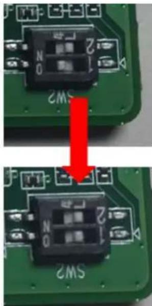
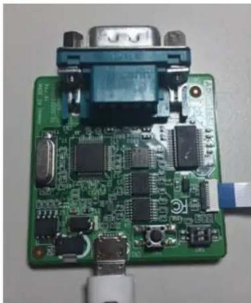
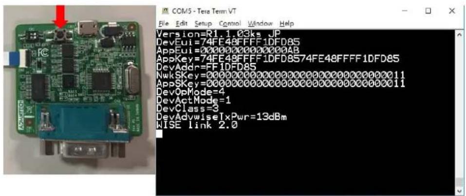
6. UART port connect via debug board
Connect USB-to-microUSB cable from WISE-ED20 to the USB port on your Windows PC. Opening the corresponding COM port in serial program, ex: Tera Term, and set the baud rate as 115200.

7. Runtime image upgrade mode
Press 'u' on the PC keyboard and "Press reset button" on ED-20 debug board. The terminal will show messages as follow.


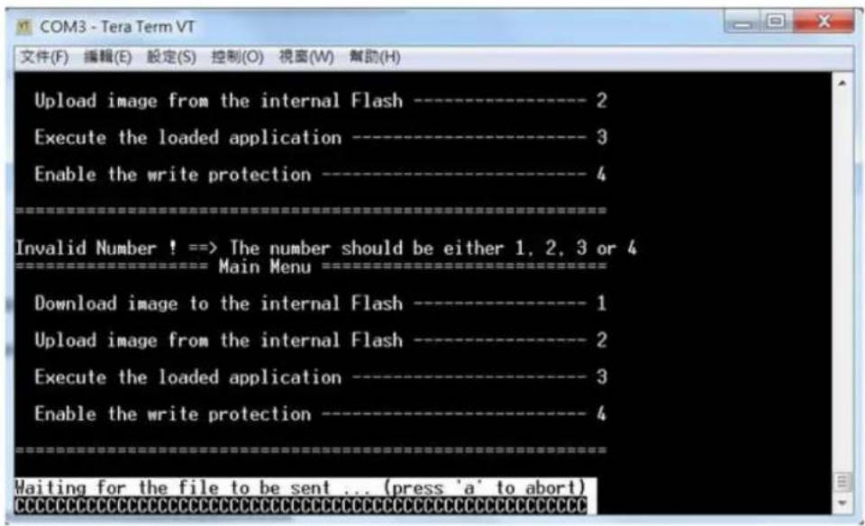
8. Start upgrading via Y modem
Select the run-time image ".bin" file via YMODEM.

Waiting for run-time image transmission is complete.

After downloading completed, the terminal will show as below.

9. Reset device
Press reset button on ED-20 debug board to reset device.
Chapter 5
Binding Process between WISE-1510 and WISE-3610
5.1 CLI Command Description
The parameters settings on WISE-3610 and WISE-1510 need to be the same. Before you had your own solution on WISELink, you can try to change the WISELink solution via CLI command.
There are 13 parameters to establish the WISE-3610 and WISE-1510 links which includes Beacon(DevOpMode), Device EUI(DevEUI), App EUI(AppEUI), App Key(AppKey), Device Class(Devclass), Activation(DevActMode), App Key(AppKey), NetWork ID(DevNetID), Data Rate(DevAdvwiseDataRate), Channel Frequency(DevAdvwiseFreq), Device Address(DevAddr), Network Session Key(NwkS-Key) and Application Session Key(AppSKey).
In this section, we will guide you to do the settings with each solution which are WISELink 1.0 with Class A ABP, WISELink 1.0 with Class C ABP, WISELink 2.0 with Class A OTAA and WISELink 2.0 with Class C OTAA. Each solution needs to adjust some parameters both on WISE-1510 and WISE-3610. Please check the following table for the detail parameter description.
| Command Option Parameters Description | |
| node get/set --AppEUI Application EUI for OTAA mode | |
| --BKey Broadcast key | |
| --AppKey | Application key for OTAA mode (16 Digit) |
| --DevAddr Device Addr for ABP mode | |
| --NwkSKey | Network session key for ABP mode (32 Digit) |
| --AppSKey | Application session key for ABP mode (32 Digit) |
| --DevNetId Device Net ID for WISE mode | |
| --DevActMode | Activation mode (1:OTAA| 2:ABP; Default:1) |
| --DevOpMode | Device operating mode (1:WISELink 1.0 | 2:LoRaWAN | 4:WISELink 2.0; Default:4) |
| --DevAdvwiseFreq Frequency Band | |
| --DevAdvwiseDataRate | Data Rate |
| --DevAdvwiseTxPwr | RF Transmit Power (dbm) |
| savecfg | Save all changes to the WISE-1510 |
| reboot | Reboot WISE-1510 |
| Command example | Description | |
| Example 1 | node get --AppEUI | Get AppEUI parameter |
| Example 2 | node set --DevAddr 11111111 | Set DevAddr is 11111111 |
| Example 3 | node savecfg | Save all changes to the WISE-1510 |
| Example 4 | node reboot | Reboot WISE-1510 |
5.2 WISELink 1.0 with Class A, ABP mode
5.2.1 Settings on WISE-1510
All the commands and steps on WISE-1510
| Steps Command Description | |
| 1. node set -devclass 1 Set devcalss to class A | |
| 2. node set --devopmode 1 Set devopmode to WISE-Link 1.0 | |
| 3. node set --devactmode 2 Set devactmode to ABP mode | |
| 4. node set --devadvwiseFreq 924500000 | Set transmit frequency as 924.5MHz |
| 5. node get --DevAddr Get DevAddr parameter | |
| 6. node get --AppSKey Get AppSKey | |
| 7. node get --NwkSKey Get NwkSkey | |
| 8. node savecfg | Save all change |
| 9. node reboot | reboot WISE-1510 |
5.2.2 Settings on WISE-3610
- Go to "WISE Manager" and "Managemet"

2. Click setting and click "Edit"
LoRa Gateway
| Gateway EUI | Region | WISE Link | Radio Frequency | Action | ||
| BEACON | ||||||
| Beacon | On | |||||
| Network ID | ||||||
| Sub Frame Index | 50 ms | |||||
| Max Tx Time | 1200 ms | |||||
| JOIN | ||||||
| Timestamp | Off | |||||
| Rejoin Period | 24 h | |||||
| SEMI PERSISTENT SCHEDULING | ||||||
| Semi-Persistent Scheduling | On | |||||
| SPS | 2,5 s | Channel Frequency | 923 900 MHz | |||
| MULTICASTING | Data Rate | DR10 - SF10/500KHz | 1.  | |||
| Multicasting | On | TX Power | 20 dBm2 | |||
3. Click "WISE Link" and turn off "Beacon" then save the setting
WISE Link

Radio Frequency
EUI 74:FE:48:FF:FF:19:D3:19
4. Check "Channel Frequency" and "Data Rate" then "Click Add LoRa Node"
LoRa Gateway
| Gateway EUI | Region | Radio Frequency #1 | Radio Frequency #2 | Action | ||
| 74FE48FFFF19D315 | TW | Channel Frequency | 520.500 MHz | Channel Frequency | 924.500 MHz | [DKSX] |
| Data Rate | DR8 - SF12/500KHz | Data Rate | DR13 - SF7/500KHz | |||
| TX Power | 20 dBm | TX Power | 20 dBm | |||
LoRa Node
| # | Device EUI | App EUI | Class | Activation | Remark | Action |
| No data available in table | ||||||
Showing 0 to 0 of 0 entries
Previous Next
Add Lofa Node
5. Fill in the WISE-1510 information in the table and save the setting
LoRa Node
General Settings
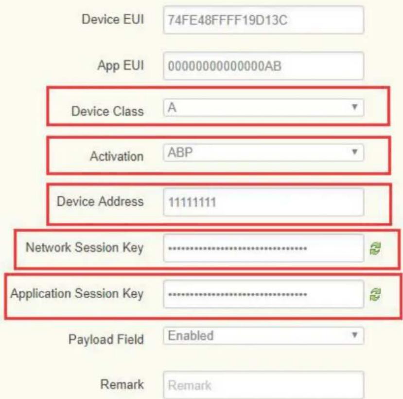
6. It will show as below

7. If the link establish, it will show as follow
5.3 WISELink 1.0 with Class C, ABP mode
5.3.1 Settings on WISE-1510
All the commands and steps on WISE-1510
Steps Command Description
| 1. node set -devclass 3 Set devcalss to class C |
| 2. node set --devopmode 1 Set devopmode to WISE-Link 1.0 |
| 3. node set --devactmode 2 Set devactmode to ABP mode |
| 4. node get --DevAddr Get DevAddr parameter |
| 5. node get --AppSKey Get AppSKey |
| 6. node get --NwkSKey Get NwkSkey |
| 7. node savecfg Save all change |
| 8. node reboot reboot WISE-1510 |
5.3.2 Settings on WISE-3610
- Go to "WISE Manager" and "Managemet"

- Click setting and click "Edit"
LoRa Gateway
| Gateway EUI | Region | WISE Link | Radio Frequency | Action |
| BEACON | ||||
| BeaconOn | ||||
| Network ID | ||||
| Sub Frame Index50 ms | ||||
| Max Tx Time1200 ms | ||||
| JOIN | ||||
| TimestampOff | ||||
| Rejoin Period24 h | ||||
| SEMI-PERSISTENT SCHEDULING | ||||
| Semi-PersistentOn | ||||
| Scheduling | ||||
| SPS2.5 s | Channel Frequency923 900 MHz | |||
| MULTICASTING | Data RateDR10 - SF10/500KHz1. | |||
| MulticastingOn | TX Power20 dBm2. |  |
- Click "WISE Link" and turn off "Beacon" then save the setting
WISE Link

Join

Radio Frequency
EUI 74:FE:48:FF:FF:19:D3:19
- Check "Channel Frequency" and "Data Rate" then "Click Add LoRa Node"
LoRa Gateway
| Gateway EUI | Region | Radio Frequency #1 | Radio Frequency #2 | Action | ||
| 74FE48FFFF19D315 | TW | Channel Frequency | 920 500 MHz | Channel Frequency | 924.500 MHz | [ccsc] |
| Data Rate | DR8 - SF12/500KHz | Data Rate | DR13 - SF7/500KHz | |||
| TX Power | 20 dBm | TX Power | 20 dBm | |||
LoRa Node
| # | 11 | Device EUI | 1↑ | App EUI | 1↑ | Class | 1↑ | Activation | 1↑ | Remark | 1↑ | Action | 1↑ |
| No data available in table | |||||||||||||
Showing 0 to 0 of 0 entries
Previous Next
Add Lola Node
- Fill in the WISE-1510 information in the table and save the setting
LoRa Node
General Settings
- It will show as below
7. If the link establish, it will show as follow

5.4 WISELink 2.0 with Class A, OTAA mode
5.4.1 Settings on WISE-1510
All the commands and steps on WISE-1510
Steps Command Description
| 1. node set -devclass 1 Set devcalss to class A | ||
| 2. node set --devopmode 4 Set devopmode to WISE-Link 2.0 | ||
| 3. | node set --devadvwiseFreq924500000 | Set transmit frequency as 924.5MHz |
| 4. node get --Appkey Get Appkey parameter | ||
| 5. node savecfg Save all change | ||
| 6. node reboot reboot WISE-1510 | ||
5.4.2 Settings on WISE-3610
- Go to "WISE Manager" and "Managemet"
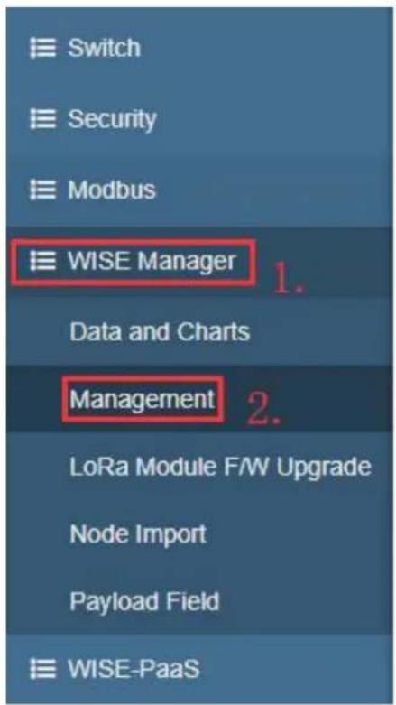
- Click setting and click "Edit"
LoRa Gateway
| Gateway EUI | Region | WISE Link | Radio Frequency | Action |
| BEACONBeaconOnNetwork IDSub Frame Index 50 msMax Tx Time 1200 msJOINTimestamp OffRejoin Period 24 hSEMI-PERSISTENT SCHEDULINGSemi-Persistent OnSchedulingSPS 2.5 sMULTICASTINGMulticasting On | Channel Frequency 923 900 MHzData Rate DR10 - SF10/500KHzTX Power 20 dBm2 | | ||
| 74FE48FFFF19D315 | TW |
3. Click "WISE Link" and turn on "Beacon" then save the setting

4. Check the Network ID is 3610 in the Beacon tag.

- For test purpose, SPS Cycle can set short time in "Semi-Persistent Scheduling".

- Click "Add LoRa Node"

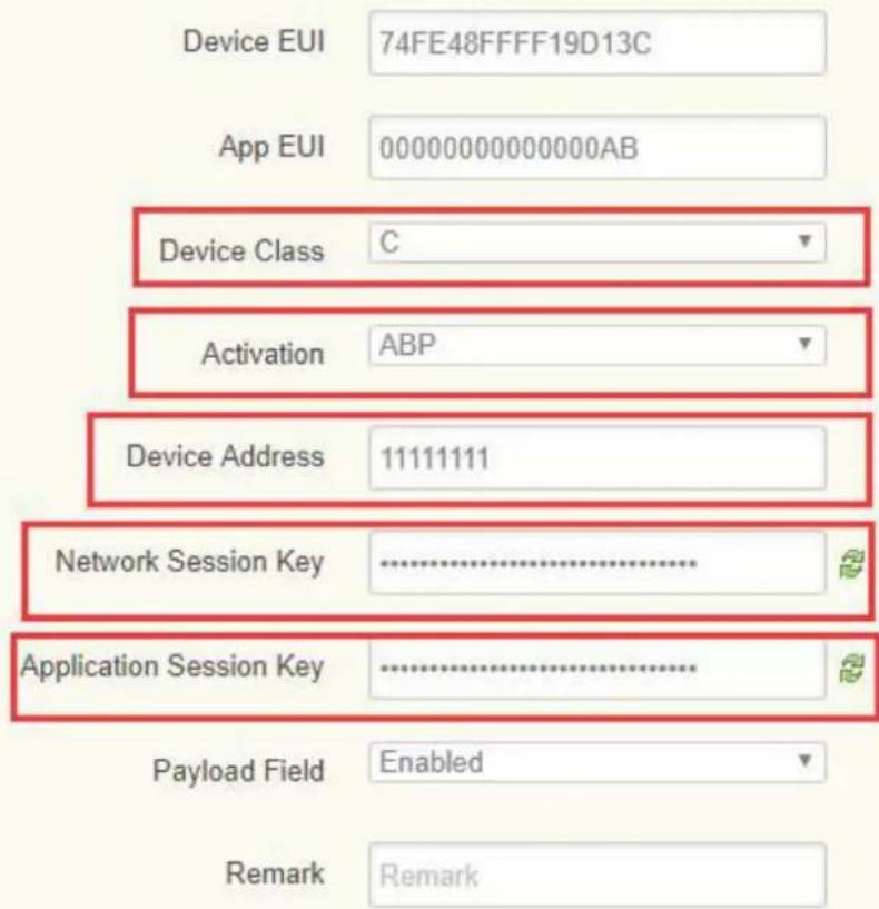
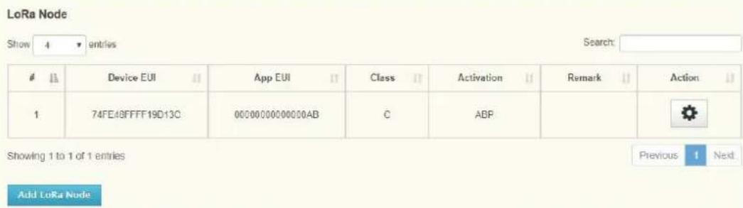
- Fill in the WISE-1510 information in the table and save the setting
LoRa Node
General Settings
Device EUI
74FE48FFFF19D13C
App EUI
00000000000000AB
Device Class
A
▼
Activation
OTAA
▼
App Key
74FE48FFFF19D13C74FE48FFFF
出
Payload Field
Enabled
▼
SPS
Enabled
▼
Remark
Remark
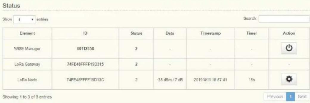
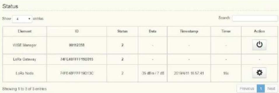
- If the link establish, it will show as follow.
Status
| Element | ID | Status | Data | Timestamp | Timer | Action |
| WISE Manager | 00112358 | 2 | - | - | - | |
| LoRa Gateway | 74FE48FFFF19D315 | 2 | - | - | - | - |
| LoRa Node | 74FE48FFFF19D13C | 2 | -35 dBm / 7 dB | 2019/4/11 16:57.41 | 15s |
Showing 1 to 3 of 3 entries
Previous 1 Next
5.5 WISELink 2.0 with Class C, OTAA mode
5.5.1 Settings on WISE-1510
All the commands and steps on WISE-1510
| Steps Command Description |
| 1. node set -devclass 3 Set devcalss to class C |
| 2. node set --devopmode 4 Set devopmode to WISE-Link 2.0 |
| 3. node get --Appkey Get Appkey parameter |
| 4. node savecfg Save all change |
| 5. node reboot reboot WISE-1510 |
5.5.2 Settings on WISE-3610
- Go to "WISE Manager" and "Managemet"
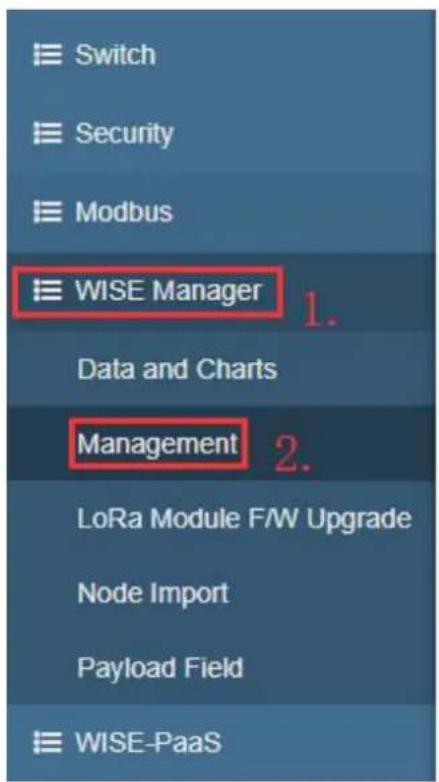
2. Click setting and click "Edit"
LoRa Gateway
| Gateway EUI | Region | WISE Link | Radio Frequency | Action | ||
| BEACON | ||||||
| Beacon | On | |||||
| Network ID | ||||||
| Sub Frame Index | 50 ms | |||||
| Max Tx Time | 1200 ms | |||||
| JOIN | ||||||
| Timestamp | Off | |||||
| Rejoin Period | 24 h | |||||
| SEMI PERSISTENT SCHEDULING | ||||||
| Semi-Persistent Scheduling | On | |||||
| SPS | 2,5 s | Channel Frequency | 923 900 MHz | |||
| 74FE48FFFF19D315 | TW | MULTICASTING | Data Rate | DR10 - SF10/500KHz | 1.  | |
| Multicasting | On | TX Power | 20 dBm2 | |||
3. Click "WISE Link" and turn on "Beacon" then save the setting
WISE Link

- Check the Network ID is 3610 in the Beacon tag.

- For test purpose, SPS Cycle can set short time in "Semi-Persistent Scheduling".

- Click "Add LoRa Node"

- Fill in the WISE-1510 information in the table and save the setting
LoRa Node
General Settings

- If the link establish, it will show as follow.
Appendix A
Application Interface Description (WISELink Application)
A.1 Application Interface Description (WISELink Application)
Please check the SDK for more information. Link as follow file://{SDK}/docs/html/index.html
Appendix B
Application Sample Code Flow
B.1 Application Sample Code Flow
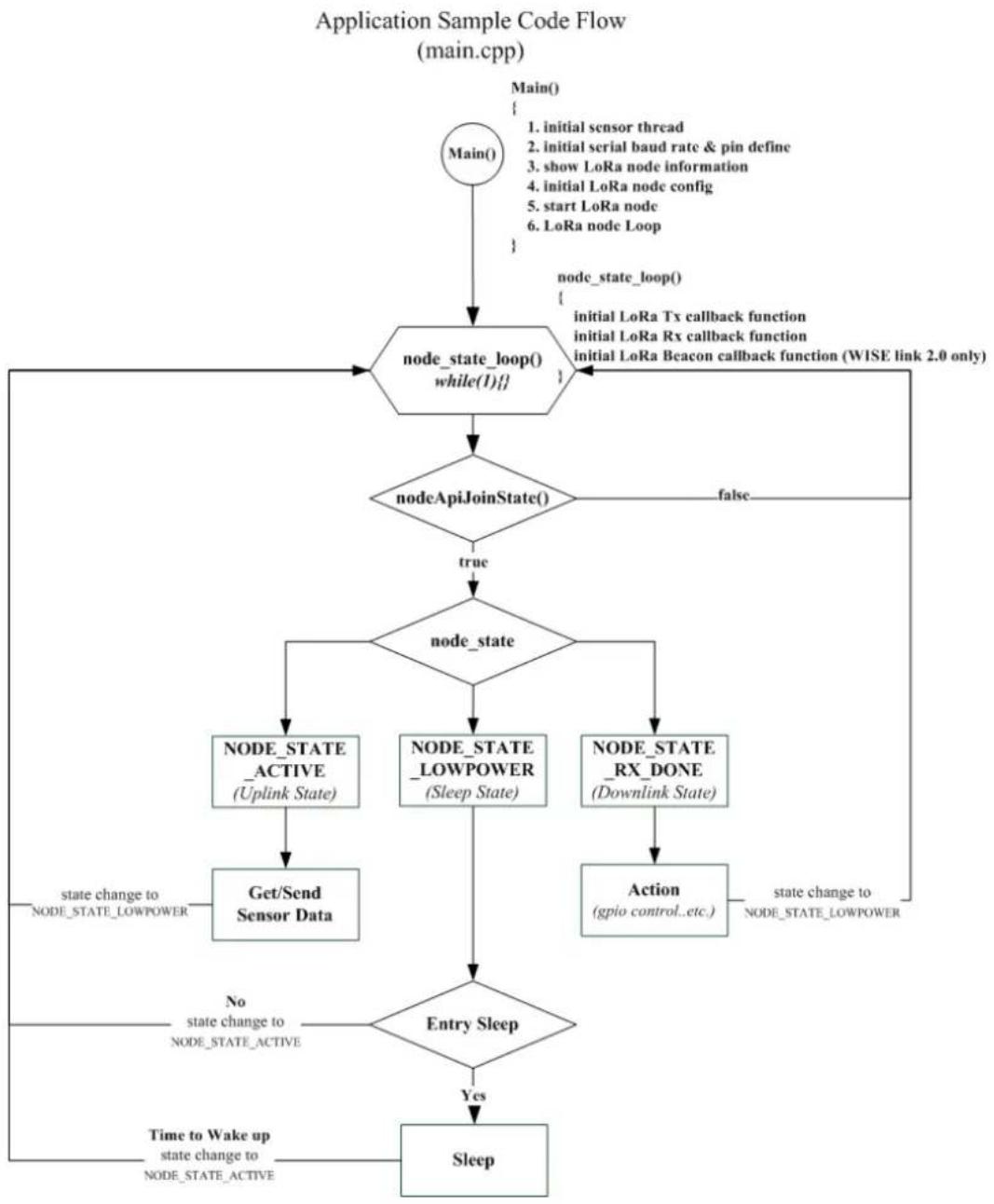
flowchart
graph TD
    A["Main()"] --> B["node_state_loop() while(I).}"]
    B --> C["nodeApiJoinState()"]
    C --> D{node_state}
    D --> E["NODE_STATE_ACTIVE (Uplink State)"]
    D --> F["NODE_STATE_LOWPOWER (Sleep State)"]
    D --> G["NODE_STATE_RX_DONE (Downlink State)"]
    E --> H["Get/Send Sensor Data"]
    F --> I["Action (gpio control...etc.)"]
    G --> J["time to Wake up state change to NODE_STATE_ACTIVE"]
    H --> K["Entry Sleep"]
    I --> K
    J --> K
    K --> L["Sleep"]
    M["Node_state_loop() {initial LoRa Tx callback function\ninitial LoRa Rx callback function\ninitial LoRa Beacon callback function (WISE link 2.0 only)}} --> C<br>    N[No state change to NODE_STATE_ACTIVE"] --> K
    O["False"] --> C
    P["State change to NODE_STATE_LOWPOWER"] --> E
Appendix C
Sensor Data Format
C.1 Sensor Data Format
In the sample application, node_get_sensor_data() encodes sensor data according to the following format:
| Length(1 Octet) | MsgType(1 Octet) | Multiple TLVs |
,where
Length: Total TLV length
MsgType: Fixed as 0xc
Multiple TLVs are one or more Tag-Length-Values: tag matches with gateway's setting, length is sensor data length, and value is sensor data. All octets are in hexadecimal.
For example, LoRa Payload Field setting on WISE-3610 is as below:

If temperature is 25.55 Celsius degree, translate decimal 2555 to hexadecimal 9FB. Similarly, if humidity is 60.55%, translate from decimal 6055 to hexadecimal 17A7. The encoded data will be
0x9 | 0xc | 0x1 | 0x3 | 0x1 | 0x9 | 0xFB | 0x2 | 0x2 | 0x17 | 0xA7
, where
0x9: the Total TLV length, included two TLVs
Oxc: the fixed MsgType
0x1 | 0x3 | 0x1 | 0x9 | 0xFB: the first TLV with tag id (0x1), value length (0x3), and positive (0x1) value (0x9FB)
0x2 | 0x2 | 0x17 | 0xA7: the second TLV with tag id (0x2), value length (0x2), and unsigned value (0x17A7)
Be reminded temperature "Sign" setting is On, 1 extra byte is required to indicate (0 means negative, and 1 means positive), but humidity "Sign" setting on gateway is Off, so no extra 1 byte is required.
Users are free to define their own payload field format, but only sensor data encoded according to the above format can be decoded successfully, and displayed on LoRa Dashboard on WISE-3610.
![assigned data: node_dct_sensor_data (ube *data) assigned data: len+1 assigned data: sensor_data[01]; mmsnet(sensor_data, value(0x1) sensor_data[len+1]=value; lm++; sensor_data[len+1]=value; lm++; sensor_data[len+1]=value; lm++; sensor_data[len+1]=value; lm++; sensor_data[len+1]=node_sensor_temp_hum>>0.0000000000000000000000000000000000000000000000000000000000000000000000000000000000000000000000 tag id (0x1) value length (byte) positive(0x0), negative(0xFF) value(temperature) tag id (0x2) value length (byte) value(humidity)](/content/2026/06/1213079/images/fb6256edc8040192121c89c6bcf3b9fec4aa0d8674a9708f4fe73c205d655ee7.jpg)
www.advantech.com
Please verify specifications before quoting. This guide is intended for reference purposes only.
All product specifications are subject to change without notice.
No part of this publication may be reproduced in any form or by any means, electronic, photocopying, recording or otherwise, without prior written permission of the publisher.
All brand and product names are trademarks or registered trademarks of their respective companies.
© Advantech Co., Ltd. 2019
- WISE-1510
- Copyright
- Acknowledgements
- Product Warranty (2 years)
- Declaration of Conformity
- FCC Class B
- FCC Caution
- IMPORTANT NOTE
- FCC Radiation Exposure Statement:
- USERS MANUAL OF THE END PRODUCT:
- LABEL OF THE END PRODUCT:
- IC
- IC Radiation Exposure Statement:
- 低功率電波輻射性電機管理辦法
- Safety Instructions
- Contents
- Chapter 1 Product Overview....1
- Chapter 2 H/W Installation....5
- Chapter 3 How to choose your solution on WISELink....17
- Chapter 4 Development Environment Setup....23
- Chapter 5 Binding Process between WISE-1510 and WISE-3610 .... 33
- Appendix A Application Interface Description (WISELink Application) 51
- Appendix B Application Sample Code Flow ..... 53
- Appendix C Sensor Data Format.... 55
- Chapter 1
- Product Overview
- Introduction
- Product Features
- Chapter 2
- H/W Installation
- Board Connector
- M2.COM Type A Module
- Module Outline
- Connector Specifications
- Top Side Connector Physical Dimensions
- Carrier Board Connection Length
- Carrier Board Connector Height
- Quick Starter of WISE-1510
- LoRaWAN and Proprietary LoRa (WISELink 1.0 and WISELink 2.0)
- Class A and Class C
- Data rate vs Distance
- Chapter 3
- Parking Lot: WISELink 1.0 with Class A, ABP mode
- Function Requirement
- Figure 3.1 Work Flow on Parking Lot solution
- Aquaculture: WISELink 1.0 with Class C, ABP mode
- Environment Monitoring: WISELink 2.0 with Class A, OTAA mode
- Factory: WISELink 2.0 with Class C, OTAA mode (Default SDK Setting)
- Chapter 4
- File Structure
- Mbed OS
- WISELink
- OS Version
- Environment Setup Procedure
- Installation
- Install Python
- (Optional) Install Git or Mercurial
- Install gcc
- Install mbed CLI
- Configuration
- Compilation
- Firmware Upgrade
- UART port connect via debug board
- Runtime image upgrade mode
- Start upgrading via Y modem
- Reset device
- Chapter 5
- CLI Command Description
- WISELink 1.0 with Class A, ABP mode
- Settings on WISE-1510
- Settings on WISE-3610
- Click setting and click "Edit"
- Click "WISE Link" and turn off "Beacon" then save the setting
- Check "Channel Frequency" and "Data Rate" then "Click Add LoRa Node"
- Fill in the WISE-1510 information in the table and save the setting
- LoRa Node
- General Settings
- It will show as below
- II Device EUI App EUI Class Activation Remark Action
- If the link establish, it will show as follow
- WISELink 1.0 with Class C, ABP mode
- Settings on WISE-1510
- Settings on WISE-3610
- Device EUI App EUI Class Activation Remark Action
- WISELink 2.0 with Class A, OTAA mode
- Settings on WISE-1510
- Settings on WISE-3610
- Click "WISE Link" and turn on "Beacon" then save the setting
- Check the Network ID is 3610 in the Beacon tag.
- WISELink 2.0 with Class C, OTAA mode
- Settings on WISE-1510
- Settings on WISE-3610
- Appendix A
- A.1 Application Interface Description (WISELink Application)
- Appendix B
- B.1 Application Sample Code Flow
- Appendix C
- C.1 Sensor Data Format
- www.advantech.com
Brand : Advantech
Model : WISE-1510
Category : IoT module