NB7530A - Soundbar LG - Free user manual and instructions
Find the device manual for free NB7530A LG in PDF.

User questions about NB7530A LG
0 question about this device. Answer the ones you know or ask your own.
Ask a new question about this device
Download the instructions for your Soundbar in PDF format for free! Find your manual NB7530A - LG and take your electronic device back in hand. On this page are published all the documents necessary for the use of your device. NB7530A by LG.
USER MANUAL NB7530A LG
Please read this manual carefully before setting your set and retain it for future reference.
NB7530A (NB7530A, NB7530A-S, S73A1-D)
Safety Information
CAUTION
RISK OF ELECTRIC SHOCK DO NOT OPEN

CAUTION: TO REDUCE THE RISK OF ELECTRIC SHOCK DO NOT REMOVE COVER (OR BACK) NO USER-SERVICEABLE PARTS INSIDE REFER SERVICING TO QUALIFIED SERVICE PERSONNEL.
This lightning flash with arrowhead symbol within an equilateral triangle is intended to alert the user to the presence of uninsulated dangerous voltage within the product's enclosure that may be of sufficient magnitude to constitute a risk of electric shock to persons.

The exclamation point within an equilateral triangle is intended to alert the user to the presence of important operating and maintenance (servicing) instructions in the literature accompanying the product.
WARNING: TO PREVENT FIRE OR ELECTRIC SHOCK HAZARD, DO NOT EXPOSE THIS PRODUCT TO RAIN OR MOISTURE.
CAUTION: The apparatus shall not be exposed to water (dripping or splashing) and no objects filled with liquids, such as vases, shall be placed on the apparatus.
WARNING: Do not install this equipment in a confined space such as a book case or similar unit.
CAUTION: Do not block any ventilation openings. Install in accordance with the manufacturer's instructions.
Slots and openings in the cabinet are provided for ventilation and to ensure reliable operation of the product and to protect it from over heating. The openings shall be never be blocked by placing the product on a bed, sofa, rug or other similar surface. This product shall not be placed in a built-in installation such as a bookcase or rack unless proper ventilation is provided or the manufacturer's instruction has been adhered to.
CAUTION concerning the Power Cord
Most appliances recommend they be placed upon a dedicated circuit;
That is, a single outlet circuit which powers only that appliance and has no additional outlets or branch circuits. Check the specification page of this owner's manual to be certain. Do not overload wall outlets. Overloaded wall outlets, loose or damaged wall outlets, extension cords, frayed power cords, or damaged or cracked wire insulation are dangerous. Any of these conditions could result in electric shock or fire. Periodically examine the cord of your appliance, and if its appearance indicates damage or deterioration, unplug it, discontinue use of the appliance, and have the cord replaced with an exact replacement part by an authorized service centre. Protect the power cord from physical or mechanical abuse, such as being twisted, kinked, pinched, closed in a door, or walked upon. Pay particular attention to plugs, wall outlets, and the point where the cord exits the appliance. To disconnect power from the mains, pull out the mains cord plug. When installing the product, ensure that the plug is easily accessible.
This device is equipped with a portable battery or accumulator.
Safety way to remove the battery or the battery from the equipment: Remove the
old battery or battery pack, follow the steps in reverse order than the assembly. To prevent contamination of the environment and bring on possible threat to human and animal health, the old battery or the battery put it in the appropriate container at designated collection points. Do not dispose of batteries or battery together with other waste. It is recommended that you use local, free reimbursement systems batteries and accumulators. The battery shall not be exposed to excessive heat such as sunshine, fire or the like.
Disposal of your old appliance

- When this crossed-out wheeled bin symbol is attached to a product it means the product is covered by the European Directive 2002/96/EC.
- All electrical and electronic products should be disposed of separately from the municipal waste stream via designated collection facilities appointed by the government or the local authorities.
- The correct disposal of your old appliance will help prevent potential negative consequences for the environment and human health.
- For more detailed information about disposal of your old appliance, please contact your city office, waste disposal service or the shop where you purchased the product.
For Ukraine only
The equipment complies with requirements of the Technical Regulation, in terms of restrictions for the use of certain dangerous substances in electrical and electronic equipment.
Disposal of waste batteries/accumulators

- When this crossed-out wheeled bin symbol is attached to batteries/accumulators of Your product it means they are covered by European Directive 2006/66/EC.
- This symbol may be combined with chemical symbols for mercury(Hg), cadmium(Cd) or lead(Pb) if the battery Contains more that 0.0005% of mercury, 0.002% of cadmium or 0.004% of lead.
- All batteries/accumulators should be disposed separately from the municipal waste stream via designated collection facilities appointed by the government or the local authorities.
- The correct disposal of Your old batteries/accumulators will help to prevent potential negative consequences for the environment, animal and human health.
- For more detailed information about disposal of Your old batteries/accumulators, please contact Your city office, waste disposal service or the shop where You purchased the product.
Europe Notice
CE 0984①
LG Electronics hereby declares that this/these product(s) is/are in compliance with the essential requirements and other relevant provisions of Directive 1999/5/EC, 2004/108/EC, 2006/95/EC, 2009/125/EC and 2011/65/EU.
Please contact to the following address for obtaining a copy of the DoC (Declaration of Conformity).
Contact office for compliance of this product :
LG Electronics Inc.
EU Representative, Krijgsman 1,
1186 DM Amstelveen, The Netherlands
- Please note that this is NOT a Customer Service contact point. For Customer Service Information, see Warranty Card or contact the dealer that you purchased this product.
Indoor Use Only
RF Radiation Exposure Statement
This equipment should be installed and operated with minimum distance 20 cm between the radiator and your body.
For Hong Kong only
IMPORTANT SAFETY NOTICE
The cord grip for the plug fitted to this product is built into the existing power cord as supplied. If, for any reason you need to shorten the cord.
DO NOT RE-USE THE PLUG
A new plug must be used to ensure your continued safety by securing the plug to the power cord in accordance with Plug & Socket Regulations 1994.
Table of Contents
1 Getting Started
2 Safety Information
6 Unique features
6 Introduction
6 - Symbols used in this manual
6 Accessories
7 Sound bar system
8 Setting up the sound bar system
8 - Attach the sound bar to the TV
11 - Pairing the sound bar system
2 Operating
12 Speaker setup
3 Troubleshooting
13 Troubleshooting
4 Appendix
14 Specifications
15 Trademarks and licenses
15 Maintenance
15 - Handling the unit
Unique features
LG Sound Sync
Controls this unit by the remote control of your LG TV that is compatible with LG Sound Sync.
Introduction
Symbols used in this manual
Note
Indicates special notes and operating features.
Caution
Indicates cautions for preventing possible damages from abuse.
Accessories
Please check and identify the supplied accessories.

natural_image
Simple line drawing of a rectangular device with a cable attached, no text or symbols present.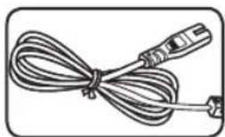
natural_image
Illustration of a coiled cable with connectors (no text or symbols)AC adapter (2) Power cord (2)
natural_image
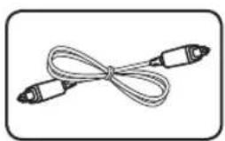
Simple line drawing of a cord with two connectors (no text or symbols)
natural_image
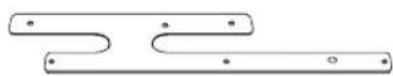
Pure diagram of two symmetrical U-shaped structures with dotted lines and a central horizontal line, no text or symbols present.Optical cable (1) TV center bracket (2)

natural_image
Pure electrical circuit lines without any symbols
natural_image
Pure electrical circuit lines without any symbolsBracket cover (Right)
(1)
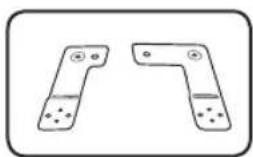
natural_image
Two identical L-shaped metal components with holes, shown in side and top views (no text or symbols)Bracket cover (Left) (1)
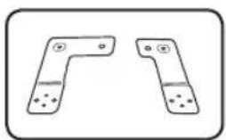
natural_image
Two identical L-shaped metal bracket components with holes and mounting holes, shown in side profile (no text or symbols)Bracket (R1 UP (1) / R2 DOWN (1))

natural_image
Simple line drawing of a screw with a star-shaped head (no text or symbols)Bracket
(L2 DOWN (1) / L1 UP (1))

natural_image
Simple line drawing of a screw with a star-shaped head (no text or symbols)Screw (8)
( 3.0 mm x 8 mm)

natural_image
Simple line drawing of a screw with a star-shaped head (no text or symbols)Screw (16)
(φ3.0 mm × 14 mm)
Screw (8)
(M 4.0 mm x 26 mm)
Sound bar system

text_image
L channel* (NB7530A) S/W Download Connector Only for service. Optical IN DC IN Connect the TV by using an optical cable. OPTICAL IN DC IN Connect the AC adapter. PAIRING PAIRING DC IN Pair the R channel sound bar and the L channel sound bar. R channel* (NB7530A-S) LED indicator * : The positions of the L (Left) channel and the R (Right) channel are as seen in front of your TV.You can check the current state of the unit by the color LED on the L channel sound bar. Refer to the table below.
| LED ColorLED State | Red Green | |
| Off Power on or disconnected power cord | ||
| On Standby - | ||
| Blink(Twice per second) | Booting - | |
| Blink(Once per second) | Mute - | |
| On -> Off(After 3 seconds) | - Power on | |
Setting up the sound bar system
Preparation
Check the supplied accessories below.

TV center bracket (2)


Brackets (R1 UP / R2 DOWN / L2 DOWN / L1 UP)

Bracket cover (Left)
Bracket cover (Right)

M 4.0 mm x 26 mm (8 EA)

3.0 ~mm × 14 ~mm (16 EA)

φ 3.0 mm × 8 mm (8 EA)
Attach the sound bar to the TV
- Attach the TV center bracket on the sound bar with the screws ( 3.0 mm x 14 mm).
natural_image
Technical line drawing of a mechanical component with mounting flanges and internal channels (no text or symbols)- Connect the AC adaptor cable and the optical cable to the sound bar. (Only the L channel sound bar has the OPTICAL IN connector.)

text_image
OPTICAL IN DC IN Optical cable AC Adapter cable- Arrange the cables to cable holder on TV center bracket. At this point, the AC adapter cable must be on the outside of the cable holder.

Note
Arranging the AC adaptor cable, you have to fix the cable below the cable holder. Refer to the image below.

natural_image
Diagram of a cable being inserted into a container (no text or symbols)- Attach the bracket cover on the sound bar with the screws ( 3.0 mm x 8 mm, Tighten the screws less than 4 torque.).

text_image
Bracket cover (Left)
text_image
Bracket cover (Right)- Attach the bracket (R1 UP/R2 DOWN/L1 UP/L2 DOWN) on the sound bar with the screws ( 3.0 mm x 14 mm).

text_image
L1 UP bracket L2 DOWN bracket
text_image
R1 UP bracket R2 DOWN bracket1
Getting Started
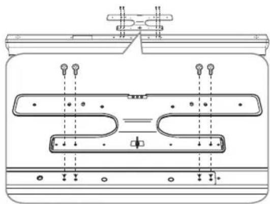
- Loosen the screws on the right side and the left side on the back of the TV.

natural_image
Pure diagram of four vertical lines with arrows pointing to each, no text or symbols present-
Attach the sound bar to the TV with the screws (M 4.0 mm x 26 mm).
-
Connect the optical input on the L channel sound bar to the optical output on the TV by using the optical cable.

text_image
OPTICAL OUT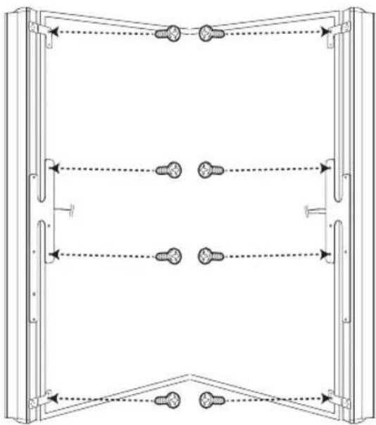
natural_image
Technical line drawing of a mechanical assembly with multiple vertical supports and bolted joints (no text or symbols)Pairing the sound bar system
Setting up the sound bar system for the first time
Connect every power cord of the sound bar system to the outlet. The color LEDs on each of the sound bar system start to blink and then they are paired automatically. Refer to the table below.
When connection is completed, the yellow-green LED on the subwoofer is turned on and the green LED on the L channel sound bar is lit up for about 3 seconds.
Note
- If you operate main unit then wireless subwoofer sound within a few seconds in standby mode.
- Set the distance between this unit and wireless subwoofer within 10 m (32 ft.).
- Optimum performance can be implemented only when the unit and the Wireless subwoofer within distance of 2 m (6 ft.) to 10 m (32 ft.) is used since communication failure may occur if longer distance is used.
- It takes a few seconds (and may take longer) for the unit and subwoofer to communicate with each other.
- If there is a strong electromagnetic wave product nearby, interference may occur. Put the unit (wireless receiver, wireless speakers, wireless subwoofer, and main unit) away from there.
When the sound bar system is not paired automatically
When there is no sound from the R channel sound bar or the wireless subwoofer, you have to pair the sound bar system manually. You can check the disconnected state by the color LED on each of the sound bar system. Refer to the table below.
Before pairing manually, make sure that every sound bar system is turned on.
- Press the buttons (Yellow, 2, 5, 8, 0, Red) on the TV's remote control toward the L channel sound bar. The red LED on the L channel sound bar starts to blink.
- Press and hold PAIRING on the R channel sound bar for about 5 seconds. The red and the green LEDs start to blink alternately.
Note

text_image
Technical diagram showing a hand holding a tool near a vertical panel with an arrow indicating direction or force.Pressing PAIRING on the R channel sound bar, you should use a shape object such as a pen.
- Press and hold PAIRING on the wireless subwoofer for about 5 seconds. The red and the green LEDs start to blink alternately.
- Unplug all the sound bar system.
- After every LED on the sound bar system is turned off, plug the sound bar system again.
You can listen to TV sound by the sound bar system.
Information of the color LED indicators
| State L channel R channel Wireless subwoofer | |||
| Standby | Red Red Red | ||
| Initial pairing Red (Blink) Green (Blink) Yellow-green (Blink) | |||
| Pairing Green (Blink) Green (Blink) Yellow-green (Blink) | |||
| Connected | Green → Off | Green → Off | Yellow-green |
| Disconnected | Off | Green (Blink) → Red | Yellow-green (Blink) → Red |
Speaker setup
Sound Sync©
Before listening to the TV sound through the sound bar system, you have to set up [Built-In Sound Bar] as an output speaker on TV speaker setup menu.
So you can listen to the sound as well as control the wireless subwoofer by using TV's remote control.
Refer to the TV's instruction manual for the details.
Note
- Set up [Built-In Sound Bar] on the TV speaker setup menu to listen normally to the sound through this sound bar system.
Because it is not supported to output the sound when the sound bar system is connected to the TV or the other device which is incompatible with the [Built-In Sound Bar] menu. - When the connections failed, make sure of the condition of the TV and power of it.
• Make sure of the condition of this unit and the connection in the cases below.
- Turned off the unit.
- Disconnecting the optical digital audio cable.
Troubleshooting
| PROBLEM CAUSE & CORRECTION | |
| No Power | The power cord is unplugged.Plug in the power cord.Check the condition by operating other electronic devices. |
| No sound | The power cord is not connected.Plug the power cord into the wall outlet securely.Pairing among the speakers gets disconnected.Connect the sound bar system. (Refer to "When the sound bar system is not paired automatically"on the page 11.) |
| The Auto power on/off function does not work. | Depending on the connected device, this function may not operate. |
Specifications
| General (NB7530A, NB7530A-S) | |
| AC adaptor requirements | Refer to the main label. |
| Power consumption | Refer to the main label. |
| Dimensions (W x H x D) (92 x 1120 x 82) mm (Each) | |
| Net Weight (Approx.) 2.7 kg (Each) | |
| Operating temperature 41 °F to 95 °F (5 °C to 35 °C) | |
| Operating humidity 5 % to 90 % | |
| Inputs (NB7530A) | |
| DIGITAL IN (OPTICAL IN) 3.0 Vrms (p-p), Optical jack |
| Amplifier | |
| Total output 310 W | |
| Stereo mode 80 W + 80 W (4 Ω at 1 kHz) | |
| Wireless subwoofer 150 W (3 Ω at 80 Hz) | |
| THD 10 % | |
| Wireless subwoofer (S73A1-D) | |
| Power requirements | Refer to the main label. |
| Power consumption | Refer to the main label. |
| Type 1 Way 1 Speaker | |
| Impedance 3 Ω | |
| Rated Input Power 150 W | |
| Max. Input Power | 300 W |
| Net Dimensions (W x H x D) | (296 X 332 X 296) mm |
| Net Weight 7.64 kg | |
- Designs and specifications are subject to change without prior notice.
Trademarks and licenses
DOLBY.
DIGITAL
Manufactured under license from Dolby Laboratories. Dolby and the double-D symbol are trademarks of Dolby Laboratories.

2.0 Channel
Manufactured under license under U.S. Patent Nos: 5,956,674; 5,974,380; 6,487,535 & other U.S. and worldwide patents issued & pending. DTS, the Symbol, & DTS and the Symbol together are registered trademarks & DTS 2.0 Channel is a trademark of DTS, Inc. Product includes software. © DTS, Inc. All Rights Reserved.
Maintenance
Handling the unit
When shipping the unit
Please save the original shipping carton and packing materials. If you need to ship the unit, for maximum protection, re-pack the unit as it was originally packed at the factory.
Keeping the exterior surfaces clean
- Do not use volatile liquids such as insecticide spray near the unit.
- Wiping with strong pressure may damage the surface.
- Do not leave rubber or plastic products in contact with the unit for a long period of time.
Cleaning the unit
To clean the player, use a soft, dry cloth. If the surfaces are extremely dirty, use a soft cloth lightly moistened with a mild detergent solution. Do not use strong solvents such as alcohol, benzine, or thinner, as these might damage the surface of the unit.

LG
Life's Good