
TDN12240G - Coffee maker LG - Free user manual and instructions
Find the device manual for free TDN12240G LG in PDF.


| Product Type | Gas Dryer (also compatible with electric models) |
| Brand | LG |
| Model | TDN12240G |
| Dimensions (W x D x H) | 685.8 x 759.4 x 982.9 mm (27.0 x 29.9 x 38.7 in) |
| Weight | 57.2 kg (126 lbs) |
| Capacity | 198 L (7.0 cu ft) |
| Power Rating | 127 V, 60 Hz, 400 W (gas model); 240 V, 30 A (electric model) |
| Energy Source | Natural Gas or LP Gas (convertible) |
| Drying Programs | Sensor Dry (Cotton/Towels, Normal, Delicates), Manual Dry (Speed Dry, Air Dry), Time Dry, Custom Program |
| Temperature Settings | High, Medium, Low, Ultra Low, Air Dry (no heat) |
| Options | Child Lock, Wrinkle Care, Damp Dry Beep, Beeper Volume |
| Display | LED with cycle status, estimated time, check filter reminder, error codes |
| Lint Filter | Clean before or after each load; washable with nylon brush |
| Exhaust Duct | 4-inch (10.2 cm) rigid or flexible metal, vent to outside |
| Safety Features | Grounding, gas shut-off valve, child lock, door safety switch |
| Installation | Leveling legs, minimum 18 in clearance for garage, reversible door |
| Accessories Included | None (pedestal and stacking kit sold separately) |
| Warranty | Residential: full warranty; non-single family: 90 days |
| Material | Steel cabinet with crystal-clear glass door |
Frequently Asked Questions - TDN12240G LG
User questions about TDN12240G LG
0 question about this device. Answer the ones you know or ask your own.
Ask a new question about this device
Download the instructions for your Coffee maker in PDF format for free! Find your manual TDN12240G - LG and take your electronic device back in hand. On this page are published all the documents necessary for the use of your device. TDN12240G by LG.
USER MANUAL TDN12240G LG
Electric and Gas Dryer
TDN12240G
Thank you for buying an LG Dryer.
Please read your manual carefully, As it provides instructions on safe Installation, use and maintenance.
Record the model and serial numbers, and retain the manual for future reference.
PRODUCT FEATURES
OUTSTANDING PERFORMANCE
Not to mention unmatched big capacity, you can benefit from good time efficiency, quiet operation and energy saving system.

ARTISTIC DESIGN
Modern front panel look and big crystal-clear glass door make your house look stylish.

DIGITAL FABRIC CARE
Multi-level temperature control heater takes a better care on your valued clothes.

EASY OF USE
A whole selection of user-friendly functions always make you comfortable with dryer operation.
What are Sensor Dry and Time Dry?
Your dryer provides sensor drying and time drying programs.
Sensor Dry
The dryer senses the dampness of the laundry and automatically determines the heat level and operation time. You might see a sudden increase or decrease in operation time if the sensor determines more or less drying is required. This is not a malfunction.
Time Dry
Use TIME DRY to select heat level and drying time manually. This can be used if clothes are not as dry as you like them at the end of the cycle. Use TIME DRY for heavy and bulky items and thick work.
TABLE OF CONTENTS
PART 1. SPECIFICATIONS ....3
PART 2. IMPORTANT WARRANTY AND SAFETY INSTRUCTIONS ....4
PART 3. INITIAL STEPS FOR INSTALLING YOUR DRYER ....11
PART 4. ACCESSORIES INSTALLATION ....17
PART 5. ELECTRICAL REQUIREMENTS FOR ELECTRIC DRYERS ....19
PART 6. ELECTRICAL REQUIREMENTS FOR GAS DRYERS....23
PART 7. GAS REQUIREMENTS AND INSTRUCTIONS....24
PART 8. EXHAUST REQUIREMENTS AND MAINTENANCE....25
PART 10. TROUBLESHOOTING GUIDE....33
Part 1 SPECIFICATIONS

■ Type : Gas Dryer
■ Rating : 127V \~ 60 Hz 400W
■ Size : 685.8 x 759.4 x 982.9 (mm)
■ Capacity : 198 L
■ Weight : 57.2 kg
* Specifications are subject to change by manufacturer.
ACCESSORIES
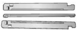
Stacking Kit Purchased Separately
See page 17 for instructions. See page 18 for instructions.

* Design of pedestals is subject to change without manufacturers notice.
Pedestal Purchased Separately
SEEKING WARRANTY SERVICE
The warranty for your dryer is located at the end of this manual. Warranty Service is available by contacting your nearest LG Service Center. If this product is installed and operated according to the instructions in this manual, LG will repair or replace any parts defective in material or workmanship throughout the warranty period, beginning with the date of purchase.

WARNING!
For your safety, the recommendations in this manual must be followed. To reduce the risk of fire or explosion, electric shock or to prevent property damage, personal injury, or death when using your appliance follow basic precautions.
Warranty Restriction: If the dryer is subjected to other than single family use, all warranty coverage is effective for only 90 days.
You will need the complete model and serial number when requesting warranty service. proof of purchase date is required.
Use the space below to record the model number and serial number of your new LG dryer.
Model Number.
Serial Number.
Date of Purchase
* Staple your receipt here for convenience when contacting service.
Part 2 IMPORTANT WARRANTY AND SAFETY INSTRUCTIONS
READ ALL INSTRUCTIONS BEFORE USE
WARNING
For your safety, the information in this manual must be followed to minimize the risk of fire or explosion, electric shock, or to prevent property damage, personal injury, or loss of life.
Your Safety and the safety of others are very important.
We have provided many important safety messages in this manual and on your appliance. Always read and obey all safety messages.

This is the safety alert symbol.
This symbol alerts you to potential hazards that can kill or hurt you and others.
All safety messages will follow the safety alert symbol and either the word DANGER or WARNING.
These words mean:
DANGER
You can be killed or seriously injured if you don't Immediately follow instructions.
WARNING
You can be killed or seriously injured if you don't follow instructions.
All safety messages will tell you what the potential hazard is, tell you how the reduce the chance of injury, and tell you what can happen if the instructions are not followed.
BASIC SAFETY PRECAUTIONS
WARNING
To reduce the risk of fire, electric shock or injury to persons when using your appliance, follow basic precautions, including the following :
- Read all instructions before using the dryer.
- Before use, the dryer must be properly installed as described in this manual.
- Do not place items exposed to cooking oils in your dryer. Items contaminated with cooking oils may contribute to a chemical reaction that could cause a load to catch fire.
Do not dry articles that have been previously cleaned in, washed in, soaked in, or spotted with gasoline, dry-cleaning solvents, other flammable or explosive substances as they give off vapors that could ignite or explode. - Do not reach into the dryer if the drum is moving.
- Do not repair or replace any part of the dryer or attempt any servicing unless specifically recommended in this Use and Care Guide or in published user-repair instructions that you understand and have the skills to carry out.
- Do not tamper with controls.
-
Before the dryer is removed from service or discarded, remove the door to the drying compartment.
-
Do not allow children to play on or in the dryer. Close supervision of children is necessary when the dryer is used near children.
- Do not use fabric softeners or products to eliminate static unless recommended by the manufacturer of the fabric softener or product.
- Do not use heat to dry articles containing foam rubber or similarly textured rubber-like materials.
- Keep area around the exhaust opening and adjacent surrounding areas free from the accumulation of lint, dust, and dirt.
- The interior of the dryer and exhaust vent should be cleaned periodically by qualified service personnel.
- Do not install or store the dryer where it will be exposed to the weather.
- Do not reach into the dryer while parts are moving.
- Always check the inside of the dryer for foreign objects
- Clean lint screen before or after each load.
SAVE THESE INSTRUCTIONS
Part 2 IMPORTANT WARRANTY AND SAFETY INSTRUCTIONS
READ ALL INSTRUCTIONS BEFORE USE
⚠ WARNING For your safety, the information in this manual must be followed to minimize the risk of fire or explosion, electric shock, or to prevent property damage, personal injury, or loss of life.
- Do not store or use gasoline or other flammable vapors and liquids in the vicinity of this appliance or any other appliance.
- Installation and service must be performed by a qualified installer, service agency, or the gas supplier.
BASIC SAFETY PRECAUTIONS
⚠ WARNING To reduce the risk of fire, electric shock or injury to persons when using your appliance, follow basic precautions, including the following :
GROUNDING INSTRUCTIONS
This appliance must be grounded. In the event of malfunction or breakdown, grounding will reduce the risk of electric shock by providing a path of least resistance for electric current. This appliance must be equipped with a cord having an equipment-grounding conductor and a grounding plug. The plug must be plugged into an appropriate outlet that is properly installed and grounded in accordance with all local codes and ordinances.
WARNING - Improper connection of the equipment- rounding conductor can result in a risk of electric shock. Check with a qualified electrician or service person if you are in doubt as to whether the appliance is properly grounded.
Do not modify the plug provided with the appliance.
If it will not fit the outlet, have a proper outlet installed by a qualified electrician.
This appliance must be connected to a grounded metal, permanent wiring system or an equipment-grounding conductor must be run with the circuit conductors and connected to the equipment-grounding terminal or lead on the appliance.
Part 2 IMPORTANT WARRANTY AND SAFETY INSTRUCTIONS
READ ALL INSTRUCTIONS BEFORE USE
WARNING
For your safety, the information in this manual must be followed to minimize the risk of fire or explosion, electric shock, or to prevent property damage, personal injury, or loss of life.
WHAT TO DO IF YOU SMELL GAS
WARNING
To reduce the risk of fire, electric shock, or injury to persons when using the appliance, follow basic precautions, including the following:
- Do not try to light a match or cigarette, or turn on any gas or electrical appliance.
- Do not touch any electrical switches. Do not use any phone in your building.
-
Clear the room, building, or area of all occupants.
-
Immediately call your gas supplier from a neighbor's phone. Follow the gas supplier's phone. Follow the gas supplier's instructions carefully.
- If you cannot reach your gas supplier, call the fire department.
Part 2 IMPORTANT WARRANTY AND SAFETY INSTRUCTIONS
READ ALL INSTRUCTIONS BEFORE USE

WARNING
For your safety, the information in this manual must be followed to minimize the risk of fire or explosion, electric shock, or to prevent property damage, personal injury, or loss of life.
SAFETY INSTRUCTION FOR INSTALLATION

WARNING
To reduce the risk of fire, electric shock, or injury to persons when using the appliance, follow basic precautions, including the following:
- Properly ground dryer to conform with all governing codes and ordinances. Follow details in the installation instructions.
Electrical shock can result if the dryer is not properly grounded. - Before use, the dryer must be properly installed as described in this manual.
Electrical shock can result if the dryer is not properly grounded.
• Install and store the dryer where it will not be exposed to temperatures below freezing or exposed to the weather.
All repairs and servicing must be performed by an authorized servicer unless specifically recommended in this Owner's Guide. Use only authorized factory parts.
Failure to follow this warning can cause serious injury, fire, electrical shock or death. -
Do not install the washer in humid spaces to reduce the risk of electric shock.
Failure to follow this warning can cause serious injury, fire, electrical shock or death. -
Connect to a properly rated, protected, and sized power circuit to avoid electrical overload.
Improper power circuit can melt, creating electrical shock and/or fire hazard. - Remove all packing items and dispose of all shipping materials properly.
Failure to do so can result in death, explosion, fire or burns. - Place dryer at least 18 in. above the floor for a garage installation.
Failure to do so can result in death, explosion, fire or burns.
Part 2 IMPORTANT WARRANTY AND SAFETY INSTRUCTIONS
READ ALL INSTRUCTIONS BEFORE USE
WARNING
For your safety, the information in this manual must be followed to minimize the risk of fire or explosion, electric shock, or to prevent property damage, personal injury, or loss of life.
SAFETY INSTRUCTION FOR INSTALLATION (cont.)
Exhaust/Ducting:
- Gas dryers MUST be exhausted to the outside.
Failure to follow these instructions can result in fire or death. - The dryer exhaust system must be exhausted to the outside of the dwelling.
The dryer is not exhausted outdoors, some fine lint and large amounts of moisture will be expelled into the laundry area. An accumulation of lint in any area of the home can create a health and fire hazard. - Use only rigid metal or flexible metal 4in. Diameter ductwork inside the dryer cabinet or for exhausting to the outside.
Use of plastic or other combustible ductwork can cause a fire. Punctured ductwork can cause a fire if it collapses or becomes otherwise restricted in use or during installation.
- Rigid or semi rigid metal ducting is recommended for use between the dryer and the wall. In special installations when it is impossible to make a connection with the above recommendations, a UL-listed flexible metal transition duct may be used between the dryer and wall connection only. The use of this ducting will affect drying time.
Failure to follow these instructions can result in fire or death.
- Ductwork is not provided with the dryer, and you should obtain the necessary ductwork locally. The end cap should have hinged dampers to prevent back draft when the dryer is not in use.
Failure to follow these instructions can result in fire or death. - The exhaust duct must be 4 in. (10 cm) in diameter with no obstructions. The exhaust duct should be kept as short as possible. Make sure to clean any old ducts before installing your new dryer.
Failure to follow these instructions can result in fire or death.
- DO NOT use sheet metal screws or other fasteners which extend into the duct that could catch lint and reduce the efficiency of the exhaust system. Secure all joints with duct tape. ¶U For complete details, follow the Installation Instructions.
Failure to follow these instructions can result in fire or death.
READ ALL INSTRUCTIONS BEFORE USE
WARNING
For your safety, the information in this manual must be followed to minimize the risk of fire or explosion, electric shock, or to prevent property damage, personal injury, or loss of life.
SAFETY INSTRUCTION FOR CONNECTING ELECTRICITY
WARNING
To reduce the risk of fire, electric shock or injury to persons when using the appliance, follow basic precautions, including the following :
- Do not, under any circumstances, cut or remove the ground prong from the power cord.
To prevent personal injury or damage to the dryer, the electrical power cord must be plugged into a properly grounded - For personal safety, this dryer must be properly grounded.
Failure to do so can result in electrical shock or injury
- Refer to the installation instructions in this manual for specific electrical requirements for your model.
Failure to follow these instructions can create electrical shock and/or a fire hazard.
- This dryer must be plugged into a properly grounded outlet.
Electrical shock can result if the dryer is not properly grounded.
- Have the wall outlet and circuit checked by a qualified electrician to make sure the outlet is properly grounded.
This will prevent shock hazard and assure stability during operating.
- The dryer should always be plugged into its own individual electrical outlet which has a voltage rating that matches the rating plate.
This provides the best performance and also prevents overloading house wiring circuits which could cause a fire hazard from overheated wires.
- Never unplug your dryer by pulling on the power cord. Always grip plug firmly and pull straight out from the outlet.
The power cord can be cut by any movement of the core, resulting in electrical shock.
- Repair or replace immediately all power cords that have become frayed or otherwise damaged. Do not use a cord that shows cracks or abrasion damage along its length or at either end.
These power cord can melt, creating electrical shock and/or fire hazard.
- When installing or moving the dryer, be careful not to pinch, crush, or damage the power cord.
This will prevent injury and damage to the dryer from fire and electrical shock.
Part 3 INITIAL STEPS FOR INSTALLING YOUR DRYER
The following instructions will help guide you through the initial steps of setting up your dryer for use. Please note that every section of this manual provides important information regarding the preparation and use of your dryer, and it is important that you review this entire manual before proceeding with any installation or use. More detailed instructions concerning electrical connections, gas connections, and exhaust requirements are provided in other parts of this manual.
STEP 1 Positioning the Dryer.
Choose a location with a solid floor for your dryer. Place the dryer at least eighteen inches above the floor for a garage installation. After placing the dryer in the desired location, please make sure that it has the required clearances shown below. If you are installing your dryer in a manufactured or mobile home, please refer to STEP 9 for additional instructions.
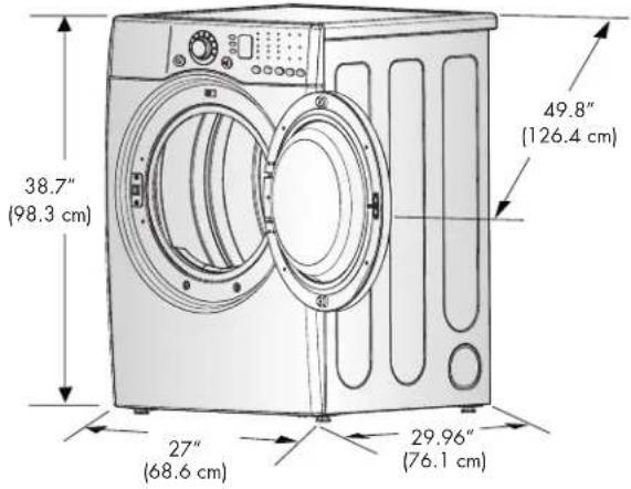
* Most installations require a minimum 5 1/2 inches. (14 cm) clearance behind the dryer for the exhaust vent with elbow.
Note
Leveling legs should be secured.
All four legs are stably placed on a solid and even floor.
If dryer is not level, laundry may not tumble properly and sensor will not detect accurate humidity information.
When leveling, please be cautious not to injure your fingers and toes.
If you install the dryer on the optional pedestal, it is nessary to level with the pedestal leveling legs.
Certain minimum clearances are required above, behind, and to the sides of the unit, as shown below. Those required minimum clearances are set forth in the picture below. Please keep the following instructions in mind when installing in a closet or recessed area:
- Consider allowing additional clearance for installation and servicing.
• Wall, door and floor molding may necessitate additional clearances.
- An additional inch of clearance is recommended to minimize noise transfer.
- Consider space needed for companion appliances.
- For closet installations, the picture below shows the minimum required ventilation openings for the door. A louvered door with comparable ventilation openings is also acceptable.
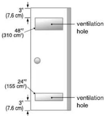

Closet-side ViewCloset Door

Closet-front View
Part 3 INITIAL STEPS FOR INSTALLING YOUR DRYER
Once in position, adjust the leveling legs of the dryer until it is level from left to right and front to back. The leveling legs must remain firmly on the floor and the dryer should not rock. The maximum slope of the dryer from left to right or front to back should not exceed 2.5 cm (1 inch). If the dryer is not level, and if the slope exceeds 2.5 cm (1 inch), a load may not tumble properly and internal sensors may malfunction. Note: Other sections of this manual also provide important information concerning the placement of and clearances for your dryer. Please review this entire manual before proceeding with any installation.
STEP 2 Procedure for Reversing the Door
The door on your dryer can be installed to open either to the left or the right. Follow these instructions to reverse the direction in which your door opens:
Note
Door and latch should be aligned at the center when closed.
1

2

3
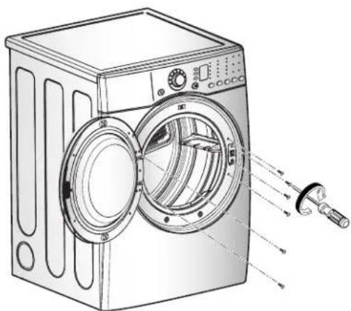
Part 3 INITIAL STEPS FOR INSTALLING YOUR DRYER
STEP 3 Connecting the Exhaust and Venting System.

WARNING!
- Use a heavy metal vent.
- Do not use plastic or thin foil duct.
- Clean old ducts before installing this dryer.
- Failure to follow these instructions can result in death or fire.
Note
The exhaust must be vented to the outside. Improper taping and incorrect installation will cause dryer malfunction.
In addition to the following warnings, please refer to manual section on Exhaust Requirements and Maintenance. Warning: The dryer must be vented to the outdoors. Please follow the instructions (and all others in this manual) very carefully. Failure to follow these instructions can result in death or fire.

- Do not use plastic or thin foil duct.
- Rigid or semi-rigid metal ducting is recommended for use as transition ducting between the dryer and and the wall. In special installations when it is impossible to make a connection with the above recommendations, then a UL-listed flexible metal transition duct may be used between the dryer and wall connection only. The use of this ducting will affect dry time.
- Position the dryer such that the exhaust duct run is as short as possible.
- Clean old ducts before installing this dryer
- The male end of each section of exhaust duct must point away from the dryer.
- Use as few elbow joints as possible.
- Use duct tape on all duct joints.
- Insulate ductwork that runs through unheated areas in order to reduce condensation and lint build-up on pipe walls.
- PLEASE BE AWARE THAT FAILURE TO EXHAUST THE DRYER CORRECTLY WILL VOID THE DRYER'S WARRANTY.
■ ALTERNATE EXHAUST DIRECTIONS
- Remove screw and exhaust duct. (Use exhaust kit part #3911EZ9131X.)

2-1. Detach and remove the knockout that matches the desired venting direction (Right side not available on Gas Dryers)
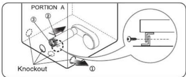
2-2. Connect a short piece of duct to the blower housing and attach the duct to the base.
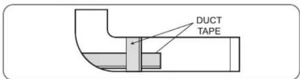
3-1. Insert the male end of a 4" elbow into the female end of a short duct. Tape the joint.

3-2. Insert this assembly elbow first through the hole in the dryer and push the female end of the elbow onto the male end of the blower output shaft. Tape the joint.

Part 3 INITIAL STEPS FOR INSTALLING YOUR DRYER
STEP 4 Connection of Gas Supply
(Gas dryer only). In addition to the following, please refer to manual section on Gas Requirements and Instructions.
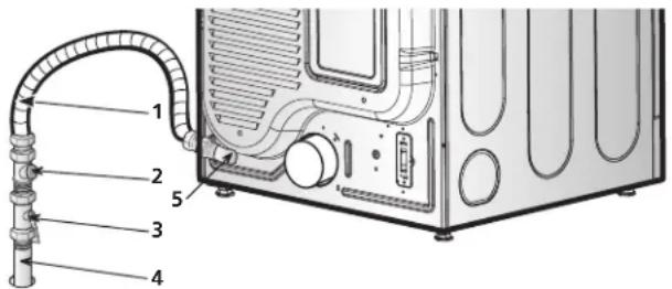
- New stainless steel flexible connector. Use this type of connector only if allowed by local codes. Use Design AGA Certified Connector.
- 1/8" NPT Pipe Plug (for checking inlet gas pressure)
- Equipment Shut-Off Valve Installed within 6' (1.8 m) of dryer.
- Iron Pipe. Shorter than 20' (6.1 m) Use 3/8" pipe. Longer than 20' (6.1 m) - Use 1/2" pipe.
- 3/8" N.P.T. Gas Connection.
Note
Make sure the burner orifice is proper for the type of gas you have.
For instance, using LPG with LNG orifice will result in death, fire or explosion. Or using LNG with LPG nozzle will not allow the burner to ignite.
If needed, orifice conversion should be done by a qualified service technician and mark or put the label of the current type of orifice on the dryer. If changing the orifice, also adjust the gas valve.
- Confirm that the type of gas available in your laundry room is appropriate for the dryer. The dryer is prepared for Natural Gas with a 3/8" NPT gas connection.
- Remove the shipping cap from the gas connection at the back of the dryer. Make sure that you don't damage the threads of the gas connection pipe when you remove the shipping cap.
- Connect the dryer to your laundry room's gas supply using a new flexible stainless steel connector (as noted below, use a new stainless steel flexible connector if allowed by your local codes).
- Securely tighten all connections between the dryer and your laundry room's gas supply. Turn on your laundry room's gas supply and check all pipe connections (both internal and external) for gas leaks with a non-corrosive leak detection fluid. Refer to Part 7 (page 20)
- For LP (Liquefied Petroleum) gas connection, refer to this manual's section entitled Gas Requirements and Instructions.
STEP 5 Electrical Plug Connections
Following are several warnings and instructions concerning making the electrical connection for electric dryers. More detailed information concerning the electrical connection is provided in the manual section entitled Electrical Requirements for Electric Dryer. It is important that you thoroughly review that section and the remainder of this manual, before taking any steps to install or use this dryer.
- Use only a new UL listed No. 10 (copper wire only) three conductor power supply cord kit rated 240 Volts (minimum) 30 Amperes and labeled as suitable for use in a clothes dryer.
- A four-wire cord is required for manufactured (mobile) home installations and where local codes do not allow grounding of this appliance through neutral.
- Electrical Plug Connections.
- For additional instruction on connecting the dryer to an electrical power source, please refer to this manual's section on Electrical Requirements and Electric Dryer.
Note
Burner input requirements
If your house is located at the elevations up to 10,000 feet.
Adjusting burner input setting is not needed at this elevation because AGA certifies this dryer will not have any problem with the BTU rating at this altitude.
If your house is above 10,000 feet, you are required to adjust a four percent (4%) reduction of the burner BTU rating indicated on the model/serial rating plate.
WARNING!
- Use a new UL listed 30 amp power supply cord.
- Use a UL approved strain relief.
- Disconnect power before making electrical connections.
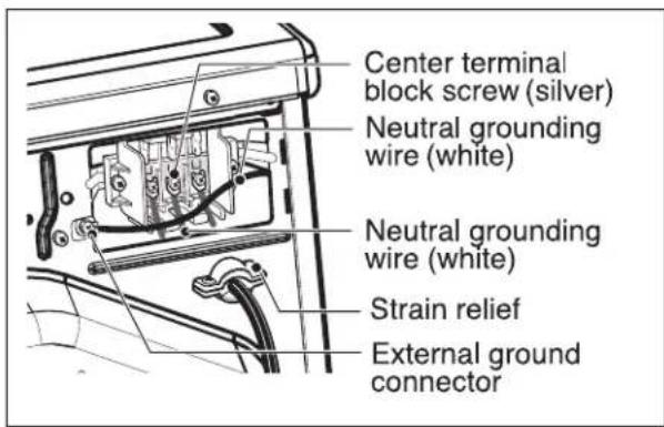
- Connect neutral wire (white or center wire) to center terminal.
- Ground wire (green or bare wire) must be connected to green ground connector.
- Securely tighten all electrical connections
- See installation instructions for complete instructions.
- Failure to do so can result in fire or electrical shock.
Part 3 INITIAL STEPS FOR INSTALLING YOUR DRYER
STEP 6 Preparation of the Dryer.
Prior to the first use of this appliance, use all-purpose cleaning products or a solution of detergent and water, with damp cloth to remove from the inside of the dryer drum/drying compartment any dust or dirt that may have accumulated inside the dryer. Plug-in your dryer after reviewing the following parts on your dryer's Electrical Requirements.
STEP 7 Confirming Heat Source Operation.
Confirming Heat Source in Gas Dryers
Close the door to the dryer drum/drying compartment and, after completing all steps in this manual for proper installation of this dryer, start the dryer on a heat setting. After the dryer starts, the igniter will glow red and the main burner will ignite.
Warning: If all air is not purged from the gas line, the gas igniter may go off before the gas and the main burner have ignited. If this happens, the igniter will re-attempt gas ignition after approximately two minutes.
Confirming Heat Source in Electric Dryers
Close the door to the dryer drum/drying compartment and, after completing all steps in this manual for proper installation of this dryer, start the dryer on a heat setting. The exhaust air or the exhaust pipe should be warm after the dryer has been operating for three minutes.
in TDP.8
Effective dryer operation requires appropriate dryer airflow. The adequacy of the airflow can be measured by evaluating the static pressure. Static pressure in the exhaust duct can be measured with a manometer, placed on the exhaust duct approximately 2 ft. (60.9 cm) from the dryer. Static pressure in the exhaust duct should not exceed 5/8 inches (1.5 cm). The dryer should be checked while the dryer is running with no load.
Measuring Static pressure
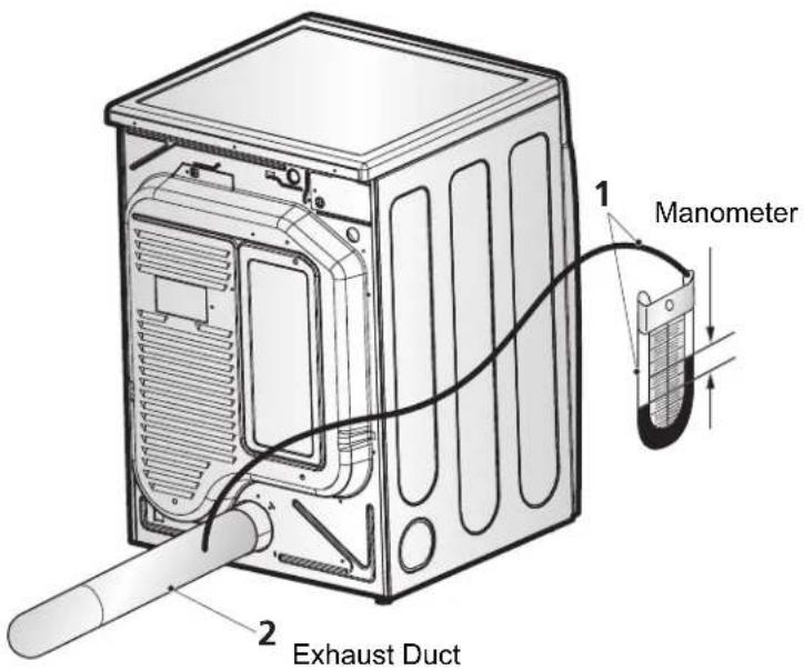
MAXIMUM STATIC PRESSURE IN WATER COLUMN
5/8 inches (1.5 cm)
Part 3 INITIAL STEPS FOR INSTALLING YOUR DRYER
STEP 9 Additional Instructions for Installation of Your Dryer in a Manufactured or Mobile Home.
The following instructions are applicable to installations of the dryer in a manufactured or mobile home. Any installation in a manufactured or mobile home must comply with the Manufactured Home Construction and Safety Standards Title 24 CFR, Part 32-80 or Standard CAN/CSA0Z240 MH and local codes and ordinances. If you are uncertain whether your proposed installation will comply with these standards, please contact a service and installation professional for assistance.
The following instructions apply to any installation of the dryer in a manufactured or mobile home:
1) The electrical connection for an electric dryer must be a 4-wire connection. More detailed information concerning the electrical connection is provided at the manual section entitled Electrical Requirements for Electric Dryer
2) To reduce the risk of combustion and fire, the dryer must be vented to the outside.
3) Electric dryers may be vented to the outside using the back, left, right, or bottom panel.
4) Gas dryers may be vented to the outside using the back, left, or bottom panel. Gas dryers may not be vented to the outside using the right side panel because of the burner housing.
5) The dryer exhaust duct must be affixed securely to the manufactured or mobile home structure, the exhaust duct must be made of a material that will resist fire and combustion, and it is recommended that you use a rigid or flexible metal pipe.
6) DO NOT connect the exhaust duct with any other duct, vent, chimney, or other exhaust duct.
7) Make sure the dryer has adequate access to outside fresh air to ensure proper operation. The opening for outside fresh air must be at least 25 in 2 (163 cm 2 ).
8) It is important that the clearance of the duct from any combustible construction be at least 2 inches (5 cm), and, when venting the dryer to the outdoors, the dryer can be installed with a clearance of 1 inch at the sides and back of the dryer.
9) Please be aware that venting materials are not supplied with the dryer. You should obtain the venting materials necessary for proper installation.
WARNING!
- DO NOT connect exhaust ducts with metal screws or fasteners that extend into the duct.
- Failure to do so can result in death, explosion, or fire.
WARNING!
- DO NOT vent the exhaust duct under the manufactured or mobile home.
- Failure to do so can result in death, explosion, or fire.
Part 4 ACCESSORIES INSTALLATION
Stacking Kit Installation Instructions
To ensure safe and secure installation, please observe the instructions below.

WARNING!
- The weight of the dryer and the height of installation makes the stacking procedure too risky for one person. This procedure should be performed by 2 or more experienced service personnel.
- Incorrect installation can cause serious accidents.
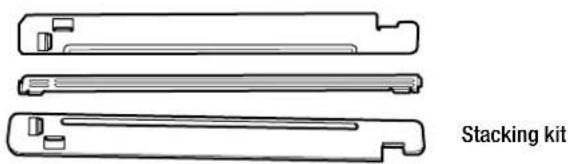
1 Place washer firmly on a stable, even and solid floor.
2 Peel protective paper off the tape from the stacking kit side bracket.

3 Fit the stacking kit side bracket firmly to the side of top plate by attaching the double-sided tape to top plate as picture shows.

Note
Clean the surface before attaching the brackets and double-sided tape.
4 Secure stacking kit side bracket to the washer with a screw on the back of bracket. Repeat Steps 2, 3, 4 for the other side.

5 Place the dryer on top of the washer by fitting legs as shown in the picture. Avoid finger injuries - be careful not to pinch fingers between the washer and dryer. Slide dryer slowly backwards to the stopper of kit.

WARNING!
- Do not stack a washer on the top of the dryer.
- Incorrect installation can cause serious accidents.

6 Insert the front rail. Push the front rail back to the stoppers of side stacking kit.

7 Attach both sides of the front kit with screws.
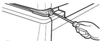
- Do not use stacking kit with a gas dryer in potentially unstable conditions like a mobile home.
Pedestal Installation Instructions
The pedestal accessory includes:
- Drawer divider (1)
- Wrench (1)
- Screws (18) †
- Retainers (4) ††
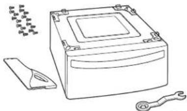
† Dryer installation only uses 8 screws †† For dryer only

Tools Needed for Installation:
• Phillips-head screwdriver
- Wrench (supplied)

To ensure safe and secure installation, please thoroughly follow the instructions below.
1 To set the dryer to the same height as the washer, fully retract the leveling feet of the dryer by turning them counterclockwise, then turn them clockwise 1-1/2 turns.
NOTE: The appliance and pedestal assembly must be placed on a solid, sturdy, level floor for proper operation.

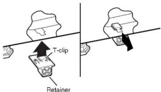
2 Insert the T-clip of the 4 retainers into the dryer base as shown. Press up on the back of the clip and pull outward to lock into place.
3 Place the dryer on the pedestal. Make sure the front and back feet are in the correct positions. The dryer feet will fit into the innermost positions as shown.

4 Make sure the screws on the pedestal align with the holes in the retainers, then install 4 screws at each corner to securely attach the appliance to the pedestal.
NOTE: If the screws are not installed properly, noise and vibration may result.
Move the appliance to the desired location.

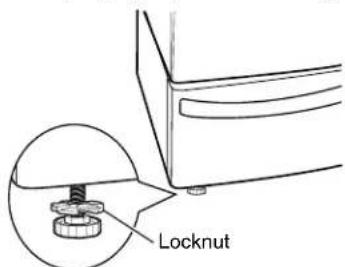
5 Loosen the locknuts on all 4 leveling feet of the pedestal until you can turn them with the wrench. Turn clockwise to raise or counterclockwise to lower until the pedestal is level and all 4 feet are solidly against the floor.

Securely tighten all locknuts by hand.
NOTE: Noise and vibration may result if locknuts are not tightened.
Be sure to connect the appliances to all water, power, or gas lines and draining or venting connections before operation.
If there is excessive vibration during the first operation after installation, slightly adjust the leveling feet.
Part 5 ELECTRICAL REQUIREMENTS FOR ELECTRIC DRYERS
The following are additional instructions regarding electrical connections and requirements for electric dryers.
Warning: The wiring and grounding must conform to the latest edition of the National Electrical Code, ANSI/NFPA 70 and all applicable local regulations. Please contact a qualified electrician to check your home's wiring and fuses to ensure that your home has adequate electrical power to operate the dryer. Failure to do so can result in fire or electrical shock.
127 V\~60 Hz, 3-Wire Installation
Instructions for Grounding of your Electric Dryer:
a) This dryer must be connected to a grounded metal, permanent wiring system or an equipment-grounding conductor must be run with the circuit conductors and connected to the equipment-grounding terminal or lead on the dryer.
b) The dryer has its own terminal block that must be connected to a separate 60 Hertz single phase AC circuit, fused at 30 Amperes (the circuit must be fused on both sides of the line). ELECTRICAL SERVICE FOR THE DRYER SHOULD BE OF MAXIMUM RATE VOLTAGE LISTED ON THE NAMEPLATE. DO NOT CONNECT DRYER TO 110, 115, OR 127 VOLT CIRCUIT.
c) If branch circuit to dryer is fifteen feet (4.50 m) or less in length, use U.L. (Underwriters Laboratories) listed No. 10 A.W.G. wire (copper wire only), or as required by local codes. If over fifteen feet (4.50 m), use U.L. (Underwriters Laboratories) listed No. 8 A.W.G. wire (copper wire only), or as required by local codes. Allow sufficient slack in wiring so dryer can be moved from its normal location when necessary.
d) The power cord (pigtail) connection between wall receptacle and dryer terminal block IS NOT supplied with dryer. Type of pigtail and gauge of wire must conform to local codes and with instructions mentioned on the following pages.
e) The method of wiring the dryer is optional and subject to local code requirements. Refer to examples on next page.
f) You must select the method by which to wire your dryer according to local code and ordinance requirements. Sample methods are included in the following pages.
Review the following options to determine the appropriate electrical connection for your home:

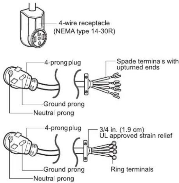
4-wire receptacle (NEMA type14-30R)
Use the instructions in this section if your home has a 4-wire receptacle (NEMA type 14-30R) and you will be using a UL listed, 120/240 volt minimum, 30 amp, dryer power supply cord.

3-wire receptacle (NEMA type10-30R)
Use the instructions in this section if your home has a 3-wire receptacle (NEMA type 10-30R) and you will be using a UL listed, 120/240 volt minimum, 30 amp, dryer power supply cord.

4-wire direct
If this type is available at your home. you will be connecting to a fused disconnect or circuit breaker box.

3-wire direct
If this type is available at your home. you will be connecting to a fused disconnect or circuit breaker box.
Note
- Connect the power supply wire to the terminal block. Colored wire should be connected to same color screw. Wire color indicated on manual is connected to the same color screw in block. Otherwise, a short or excessive current flow may result.
4-wire connection : Direct wire
Warning : Grounding through the neutral conductor is prohibited for (1) new branch-circuit installations, (2) mobile homes, (3) recreational vehicles, and (4) areas where local codes prohibit grounding through the neutral conductor. Failure to do so can result in fire or electrical shock.
Prepare minimum 5 ft (1.52 m) of length in order for dryer to be replaced.
First, peel 5 inches (12.7 cm) of covering material from end. Strip 5 inches of ground wire insulation. After cutting 1½ inch (3.8 cm) from 3 other wires peel insulation back 1 inch (2.5 cm). Make ends of 3 wires a hook shape.

Then, put the hooked shape end of the wire under the screw of the terminal block (hooked end facing to the right) and pinch the hook together and screw tightly.
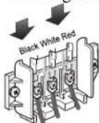
- Connect neutral wire (white) of power cord to center terminal block screw.
- Connect red and black wires to the left and right terminal block screws.
- Connect ground wire (green) of power cord to external ground screw and move neutral ground wire of appliance and connect it to center screw.
- Make sure that the strain relief screw is tightened. Be sure that all terminal block nuts are on tight and power cord is in right position.

Part 5 ELECTRICAL REQUIREMENTS FOR ELECTRIC DRYERS
3-wire connection : Direct wire
Warning : Grounding through the neutral conductor is prohibited for (1) new branch-circuit installations, (2) mobile homes, (3) recreational vehicles, and (4) areas where local codes prohibit grounding through the neutral conductor. Failure to do so can result in fire or electrical shock.
Prepare minimum 5 ft (1.52 m) of length in order for dryer to be replaced.
First, strip 3 1/2 inches (8.9 cm) of outer sheath from end and strip 1 inch of insulation from each conductor.

Then, put the hooked shape end of the wire under the screw of the terminal block (hooked end facing rightward) and pinch the hook together and tighten the screw securely.
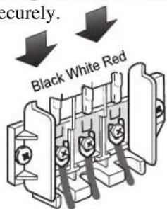
- Connect neutral wire (white) of power cord to center terminal block screw.
- Connect red and black wires to the left and right terminal block screws.
- Make sure that the strain relief screw is tightened. Be sure that all terminal block nuts are on tight and power cord is in right position.
Option 1 : 4-wire connection with a power supply cord.
- If your local codes or ordinances do not allow the use of a 3-wire connection, or you are installing your dryer in a mobile home, you must use a 4-wire connection.

- Connect neutral wire (white) of power cord to center terminal block screw.
- Connect red and black wires to the left and right terminal block screws.
- Connect ground wire (green) of power cord to external ground screw and move neutral ground wire of appliance and connect it to center screw.
- Make sure that the strain relief screw is tightened. Be sure that all terminal block nuts are on tight and power cord is in right position.
Part 5 ELECTRICAL REQUIREMENTS FOR ELECTRIC DRYERS
Option 2 : 3-Wire connection with a power supply cord.
If your local codes or ordinances permit the connection of a frame-grounding conductor to the neutral wire, use these instructions. If your local codes or ordinances do not allow the connection of a frame-grounding conductor to the neutral wire, use the instructions under Section 1: Optional 3-wire connection.
Section 1


Option 3 : Optional 3-wire connection.
- If your local codes or ordinances do not allow the connection of a frame-grounding conductor to the neutral wire, use the instructions under this section.


- Connect neutral wire (white) of power cord to center terminal block screw.
- Connect ground wire of appliance and neutral wire of power cord to center terminal block screw.
- Connect red and black wires to the left and right terminal block screws.
- Make sure the strain relief screw is tightened. Be sure that all terminal block nuts are on tight and power cord is in right position.
- Connect a independent ground wire from external ground connector to proper ground.
Part 6 ELECTRICAL REQUIREMENTS FOR GAS DRYERS
127 Volt, 60 Hertz, with 3-Prong Grounding Plug
Following are additional instructions regarding electrical connections and requirements for gas dryers.
Warning: The wiring and grounding must conform to the latest edition of the National Electrical Code, ANSI/NFPA 70, or the Canadian Electrical Code, CSA C22.1, and all applicable local regulations. Please contact a qualified electrician to check your hom's wiring and fuses to ensure that your home has adequate electrical power to operate the dryer. Failure to do so can result in fire or electrical shock.
Electrical Requirements for Your Dryer:
a) Please note that the wiring diagram is provided inside the dryer control hood. Label all wires prior to disconnection when servicing the dryer, because wiring errors can cause serious injury to you and your dryer.
b) Your dryer is designed to be used on a separate branch, polarized, three-wire, effectively grounded, 127 Volt, 60 Hertz, AC (alternating current) circuit protected by a 15 Ampere fuse, equivalent fuse or circuit breaker.
c) Use separately fused circuits for washers and dryers, and DO NOT operate a washer and a dryer on the same circuit.

WARNING!
- Do not overload the circuit by operating other appliances on the same circuit when this appliance is operating, by using an extension cord to connect the dryer to the power source, or by using any adapter to allow additional cords to connect to the same outlet.
- Failure to do so can result in fire or electrical shock.

WARNING!
- DO NOT modify the plug provided with the dryer. If it does not fit the outlet in your laundry room, a proper outlet will need to be installed in your laundry room by a qualified service person or company.
- Failure to do so can result in fire or electrical shock.

STANDARD 120 VOLT, 60 HERTZ, 3-WIRE EFFECTIVELY GROUNDED CIRCUIT
1 L1
2 Ground
3 Neutral Side
4 Round Grounding Prong
5 Neutral
a) The dryer has a three-prong plug to help guard against shock. The plug should be plugged directed into a properly grounded three-prong receptacle that is rated 127 Volts AC (alternating current) 15 Amps. This plug, in order to be properly and fully effective, must be plugged into a properly installed outlet that is grounded in accordance with all local codes and ordinances.
b) The dryer must be grounded in order to reduce the risk of electric shock, including a malfunction or breakdown.
c) If your laundry room does not meet the specifications required by this manual, or if you are uncertain whether or not your laundry room meets these specifications, please have a qualified service person or company. Review your laundry room's electrical supply for any problems.
Part 7 GAS REQUIREMENTS AND INSTRUCTIONS
Following are important instructions and information concerning the requirements for the gas supply and service for gas dryers. ⚠ Warning: The gas supply and service for a gas dryer must comply with all local codes and ordinances. In the absence of any local codes or ordinances in your area, the gas supply and service for your gas dryer must comply with the latest edition of the National Fuel Gas Code, ANSI Z223.1/NFPA 54. Failure to do so can result in death, explosion, or fire.
- Gas supply requirements: Liquefied Petroleum (L.P.) Gas (2,500 Btu/ft3 (93.1 MJ/m3)) service must be provided at 10 + 1.5 in. water column pressure.
- Do not attempt to connect the dryer to Liquified Petroleum (LP Gas) Gas service without a qualified professional.
- Isolate the dryer from the gas supply piping system by closing its individual manual shut-off valve during any pressure testing of the gas supply system at test pressure equal to or less than 2/1 psi (3.45 kPa).
- Supply Line Requirements. Your laundry room must have a rigid gas supply line to your dryer. In the United States, an individual manual shutoff valve MUST be installed within at least 6 feet (1.8 m) of the dryer, in accordance with the National Fuel Gas Code ANSI Z223.1. A 1/8 in. N.P.T. pipe plug must be installed as shown.
WARNING!
- DO NOT attempt any disassembly of the dryer. Any disassembly requires the attention and tools of an authorized and qualified service person or company.
-
Failure to do so can result in death, explosion, or fire.
-
If using a rigid pipe, the rigid pipe should be 1/2 inch IPS. If acceptable under local codes and ordinances and when acceptable to your gas supplier, 3/8 inch approved tubing may be used where lengths are less than 20 feet (6.1 m). Larger tubing should be used for lengths in excess of 20 feet (6.1 m). It is also important that you use pipe joint compound that is insoluble in LP gas.
-
To reduce the danger of gas leaks, explosion, and fire, please follow and observe the following instructions and WARNINGS.
-
Connect the dryer to the type of gas shown on the nameplate.
- Use new flexible stainless steel connectors.
- Use Teflon tape and pipe joint compound insoluble in LP gas on all pipe threads.
- Purge gas supply of air and sediment before connecting the gas supply to the dryer in order to prevent gas valve contamination. Before tightening connection between gas supply and dryer, purge remaining air until odor of gas is identified.
- DO NOT use an open flame to inspect for gas leaks; instead use a non-corrosive leak detection fluid.
WARNING!
- Use a new AGA or CSA approved gas supply line.
• Install a shut-off valve. - Securely tighten all gas connections.
- If connected to LP, have a qualified person make sure gas pressure does not exceed 13 in. water column.
• Examples of a qualified person include licensed heating personnel, authorized gas company personnel, and authorized service personnel. - Failure to do so can result in death, explosion, or fire.
Part 8 EXHAUST REQUIREMENTS AND MAINTENANCE
Following are important instructions and information concerning the exhaust requirements for your dryer.
⚠ Warning: DO NOT exhaust dryer air into an enclosed and unventilated area, such as an attic, wall, ceiling, crawl space, chimney, gas vent, or concealed space of a building. To reduce the risk of fire, DO NOT exhaust the dryer with plastic or thin foil Ducting. Failure to do so can result in death, explosion, or fire.
| Weather Hood Type | Number of 90° Elbows | Maximum length of 4” (10.2 cm) diameter rigid metal duct | Maximum length of 4” (10.2 cm) diameter flexible metal duct |
| Recommended | 0 | 65 feet (19.8 m) | 45 feet (13.7 m) |
| 1 | 55 feet (16.8 m) | 35 feet (10.7 m) | |
  (10.2 cm) (10.2 cm) (10.2 cm) (10.2 cm) | 2 | 47 feet (14.3 m) | 30 feet (9.1 m) |
| 3 | 36 feet (11.0 m) | 25 feet (7.6 m) | |
| 4 | 28 feet (8.5 m) | 20 feet (6.1 m) | |
Use Only for Short Run Installations (6.35 cm) (6.35 cm) | 0 | 55 feet (16.8 m) | 35 feet (10.7 m) |
| 1 | 47 feet (14.3 m) | 27 feet (8.2 m) | |
| 2 | 41 feet (12.5 m) | 21 feet (6.4 m) | |
| 3 | 30 feet (9.1 m) | 17 feet (5.2 m) | |
| 4 | 22 feet (6.7 m) | 15 feet (4.5m) |
NOTE : Deduct 6 feet (1.8 m) for each additional elbow. It is not recommended to use more than 4 90° elbows.
Exhaust Requirements and Instructions:
- Venting materials are not provided with the dryer and you should obtain the necessary venting materials locally. For example, the outer end of exhaust pipe must have a weather hood with hinged dampers to prevent back-draft when the dryer is not in use.
-
The exhaust duct must be four inches (10.2 cm) in diameter with no obstructions. The exhaust duct should be kept as short as possible. Make sure to clean any old ducts before installing your new dryer.
-
Rigid or semi-rigid metal ducting is recommended for use as transition ducting between the dryer and and the wall. In special installations when it is impossible to make a connection with the above recommendations, then a UL-listed flexible metal transition duct may be used between the dryer and wall connection only. The use of this ducting will affect dry time.
- DO NOT use sheet metal screws on exhaust pipe joints or other fastening means which extend into the duct that could catch lint and reduce the efficiency of the exhaust system. Secure all joints with duct tape.
- To maximize operating results, please observe the duct length limitations noted in the chart above.
Part 8 EXHAUST REQUIREMENTS AND MAINTENANCE
Exhaust and Dryer Maintenance

WARNING!
- Disconnect the dryer's electric power prior to any cleaning or maintenance.
-
Failure to do so can result in fire or electrical shock.
-
After one year of use, the interior and complete exhaust system of the dryer should be examined and cleaned if necessary.
- Before one year of use, when drying performance has become unsatisfactory, please examine and clean the exhaust duct for better drying performance.
- Check the weather hoods frequently to ensure the dampers are moving freely, that the dampers are not pushed in and that nothing has been set against the dampers.
-
A qualified service person or company should be used to perform this maintenance.
-
A Flexible Metal Vent Kit, available at extra cost, can be used to exhaust the dryer when it is placed in hard to reach places. This Kit comes in two pieces, one of which is attached to the dryer and the other is attached to the wall exhaust outlet. Following attachment of the two separate pieces to the dryer and the wall, the dryer may be returned to its final position, after which the two pieces themselves can be connected.
-
Ordinarily, the dryer drum will need no care. Wipe the exterior of the dryer as required, and always wipe the exterior of the dryer in the event any detergent, bleach, or other washing products is spilled on the dryer.
-
Clean the control panel with a damp cloth as necessary. Warning: spray pre-wash products may damage the finish of the control panel.
-
Please clean the lint filter either before drying each load or after drying each load.
-
Always make sure the lint filter is clean before starting a new load, because a clogged lint filter may increase drying times.
-
Annually remove the lint filter and attach it to the vacuum duct. See item #2 above.
-
Please note that the wiring diagram is provided inside the dryer control hood. Label all wires prior to disconnection when servicing the dryer, because wiring errors can cause serious injury to you and your dryer.
Cleaning the Lint Screen
- Clean the lint filter either before drying each load or after drying each load. Always make sure the lint filter is clean before starting a new load, because a clogged lint filter may increase drying times.
- To clean, pull the lint screen straight up and roll any lint off the screen with your fingers. Do not rinse or wash screen to remove lint. Push the lint screen firmly back into place.
- Always ensure the lint screen is firmly secured before running the dryer. Running the dryer with a loose lint screen may cause overheating and damage to the dryer and articles being dried.
- Some articles of clothing may shed more lint than others (towels for example), causing the lint screen to fill rapidly. Remove lint from the lint screen before and after drying these articles, such as new towels.
- In the event lint falls off of the lint screen and into the dryer during removal, inspect the exhaust hood and remove any lint.
- Laundry detergent and fabric softener residue can build up on the lint screen, causing longer drying times. The screen is likely blocked if lint falls off the screen. In order to prevent this type of build up, and help ensure proper operation of your dryer, clean the lint screen with a nylon brush every six months or, if necessary, more frequently. The lint filter can also be washed as follows:
a) After rolling the lint off of the screen with your fingers, wet both sides of the screen with hot or warm water.
b) Wet a nylon brush with hot water and liquid detergent and scrub the lint screen with the brush to remove the buildup of detergent and fabric softener.
c) After the residue has been removed, rinse screen with hot water.
d) After drying the lint screen with a clean towel, firmly replace the lint screen in your dryer.
Following are instructions for starting and using your new dryer. Please refer to specific sections of this manual for more detailed information. Important Warning: To reduce the risk of fire, electric shock, or injury to person, read this entire manual, including the IMPORTANT SAFETY INSTRUCTIONS, before operating this dryer.

WARNING!
Fire Hazard
- No washer can completely remove oil.
- Do not dry anything that has ever had any type of oil on it (including cooking oils).
- Items containing foam, rubber, or plastic must be air dried.
- Failure to follow these instructions can result in death or fire.
WARNING!
Explosion Hazard
- Keep flammable materials and vapors, such as gasoline, away from dryer.
- Do not dry anything that has ever had anything flammable on it (even after washing).
- Failure to follow these instructions can result in death, explosion, or fire.
1 Power Button
- Use this button for power on or off.
- Turn the knob to select the desired cycle based on laundry types and conditions.
1. Sensor Dry Cycles
Sensor Dry Cycles allow you to match the cycle to the load you are drying. Each cycle dries certain fabrics at the recommended temperature. A sensor detects the moisture in the load and automatically adjusts the drying time for optimal drying
Cotton/Towels
Use for drying denims, towels, heavy cottons.
Normal
Use for drying sturdy fabrics such as work casual clothes.
Delicates
Use for drying synthetic fabrics, washable knit fabrics and no-iron finishes.
| Sensor Dry Preset Cycle Settings | ||
| Sensor Dry Cycles Load Type | Temp. | Time* (Minutes) |
| COTTON/TOWELS Towel, denim pants | Medium High | 55 |
| NORMAL Work clothes, corduroys | Medium | 41 |
| DELICATES Lingerie, sheets, blouses | Low | 32 |
2. Manual Dry Cycles
Use Manual Cycles to select a specific amount of drying time and a drying temperature. When a Manual Cycle is selected, the ESTIMATED TIME REMAINING display shows the actual time remaining in your cycle. You can change the actual time in the cycle by pressing MORE TIME or LESS TIME.
Speed Dry
Use for small loads or loads that need a short drying time.
Air Dry
Use the Air Dry Modifier for items that require drying without heat such as rubber, plastic and heat-sensitive fabrics.
| Manual Preset Cycle Settings | ||
| Manual Dry Cycles Load Type | Temp. | Default Time* (Minutes) |
| SPEED DRY SMALL LOADS | High | 25 |
| AIR DRY | Air Dry | 30 |
3 Custom Program
Set up your favorite combination of settings and save them here for one-touch recall.

CUSTOM PROGRAM
- Select a cycle.
- Change DRY LEVEL and TEMP. CONTROL.
- Select OPTIONS you want.
- Press and hold the CUSTOM PROGRAM.
To recall your stored CUSTOM PROGRAM
Press CUSTOM PROGRAM button, then press START/PAUSE.
- Press MORE TIME or LESS TIME until the desired drying time is set.
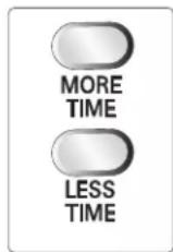
Note
Time change button is available only with Manual Dry, Time Dry and Rack Dry programs.
55 LED Display

1. CHECK FILTER REMINDER
The display will show CHECK FILTER when the dryer is turned on as a reminder to check the filter. It turns off when the START/PAUSE button is pressed.
▲ WARNING!
- For better drying performance and safety, clean lint filter every single use.
- Failure to follow these instructions can result in death or fire.
2. Estimated Time Remaining
The display shows the estimated time remaining. In addition to this, if the dryer has some problem, it displays error messages.
3. CYCLE COMPLETION INDICATOR
Shows how much of the current drying cycle has been completed.
4. STATUS/CYCLE DISPLAY
This portion of the display shows the selected cycle, operating status, and special messages. If a cycle has special instructions, they will also be displayed in this area.
60 Option Buttons

1. Child Lock
Child Lock can be used to prevent your children from changing options on control panel while the dryer is running.
When Child Lock is enabled, all the buttons will be locked and Child Lock glows.

To enable Child Lock, Press and hold OPTION for 3 seconds, A single beep tone is heard and Child Lock is displayed on the status window.
To disable Child Lock, press and hold OPTION for 3 seconds again.
2. Wrinkle Care
This option helps to prevent wrinkles in your laundry.
When you select the wrinkle free option, the dryer will periodically tumble for up to three hours after the cycle has completed.
You can use this option in case you can not remove laundry immediately after drying is done.

3. Damp Dry Beep
When you select the damp dry beep option, a beep will alert you when your load is approximately 80% dry.
This notice will allow you to remove lightweight items that are dry or other items that you may wish to iron.
| Suggested Items for Rack Drying | Temperature Setting | Suggested Time* (Minutes) |
| Washable wool items | Low | 20 |
| Stuffed toys with cotton or polyester fiber filling | Low/Ultra Low | 20/30 |
| Stuffed toys, foam rubber filled. | Air Dry/Ultra Low | 50/30 |
| Foam rubber pillows | Air Dry | 50 |
| Athletic shoes | Air Dry | 20 |
* Reset time as needed to complete drying.
7 Beeper
The BEEPER controls the volume of the beep that is made when you press any of the buttons on the control panel. Press BEEPER to adjust the sound level or turn off the signal.

8 Time Dry
Use Time Dry Option to change Drying Time on your own. You can select the desired operation time manually by pressing Time Dry button between 20 to 60 minutes.

9 Temp. Control
Use Temp. Control Option to select temperatures for the Manual Cycles. Press TEMP. CONTROL until the desired temperature setting glows. Temperature modifiers cannot be used with the Sensor Dry Cycles.

When Using Air Dry
This chart shows examples of items that can be dried using AIR DRY.
| Type of Load Default Time* (Minutes) | |
| Foam rubber-pillows, padded bras, stuffed toys | 20 - 30 |
| Plastic shower curtains, tablecloths | 20 - 30 |
| Rubber-backed rugs | 40 - 50 |
| Olefin, polypropylene, shear nylon | 10 - 20 |
Reset cycle to complete drying, if needed.
- Check to see that coverings are securely stitched.
- Shake and fluff pillows by hand periodically during the cycle.
- Dry item completely. Foam rubber pillows are slow to dry.
NOTE: Air Dry is not available with Sensor Dry Cycles.
- Use these buttons to set dry level
- First, select sensor dry cycle.
- Select dry level to adjust how much you want to dry the load. As the cycle runs, the control senses the dryness of the load and adjusts the time automatically based on the selected dryness level.
DRY LEVEL selections can only be made while using Sensor Dry Cycles. Selecting MORE Dry or LESS Dry automatically adjusts the needed time which is already sensed.
11 Start / Pause Button
- Use this button for start or pause.
Starting your dryer
1. Before use
- Clean lint screen before or after each cycle.
- Place laundry into dryer and shut door. See Loading.
- Turn the knob to select the drying cycle you want. The preset setting for Sensor Dry Cycles or Manual Cycles will glow. The estimated or actual cycle time (in minutes) will show in the display.
| Following are sample loads for Super Capacity Dryers: | |
| Heavy Work Clothes4 jeans4 workpants4 work shirts | 2 sweatpants2 sweatshirts |
| Cotton/Towels10 bath towels10 hand towels | 14 wash cloths |
| Mixed Load3 sheets (1 king, 2 twin)4 pillowcases3 shirts3 blouses | 9 T-shirts9 shorts10 handkerchiefs |
2. Loading
- Determine load size by the amount of space the load requires rather than the weight of the load.
- Avoid overloading the dryer. Following these instructions can help reduce your utility bill, prolong the life of your clothes, and decrease the likelihood of uneven drying and wrinkle.
3. To use a sensor dry cycle
- Select DRY LEVEL to adjust how dry you want the load. As the cycle runs, the control senses the dryness of the load and adjusts the time automatically for the selected dryness level.
- Select the desired options.
- Press START/PAUSE
Note
DRY LEVEL selections can only be made while using Sensor Dry Cycles. Selecting MORE Dry or LESS Dry automatically adjusts the sensed time needed.
4. To use a manual dry cycle
- Select a Manual Dry Cycle.
- Press MORE TIME or LESS TIME until the desired drying time is displayed. Tap MORE TIME or LESS TIME and the time will change by 1 minute interval.
The MORE TIME or LESS TIME feature can be used with Manual Dry and Time Dry.
- Press TEMP. CONTROL until the desired temperature indicator glows.
• (OPTIONAL STEP) If desired, select OPTIONS. For more details, see Options. - Press START/PAUSE. Be sure the door is closed.
- If you do not press START/PAUSE within 10 minutes of selecting the cycle, the dryer automatically shuts off.
- If you wish to end your drying cycle after pressing START/PAUSE, press START/PAUSE again.
To stop your dryer at any time Press START/PAUSE or open the door.
5. Pausing or restarting
• To pause the dryer at any time:
Open the door or press START/PAUSE.
• To restart the dryer
Close the door. Press START/PAUSE.
Note
Drying will continue from where the cycle was interrupted if you close the door and press START within 10 minutes. If the cycle is interrupted for more than 10 minutes, the dryer will shut off. Select new cycle settings before restarting the dryer.
Maintenance
Clean lint filter
Clean the lint filter after each use and check it before use. Not cleaning or emptying the filter will increase drying time and energy consumption, therefore dryer life expectancy could be shortened after all.
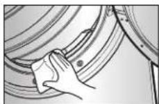
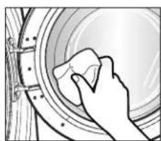
■ Clean the door and its opening
-
Wipe out the door opening. Otherwise, build-ups of dirty and foreign objects will damage sealing of door.
-
Clean the transparent glass door to keep inside view clear through the glass.
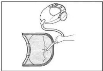
- Open the door and pull the filter straight up.

- Clean the filter using one of the following methods.
① Run the fingers across the filter.
② Vacuum the lint filter.
③ Wash the lint screen in warm, soapy water. Dry thoroughly and replace.


Part 10 TROUBLESHOOTING GUIDE
Troubleshooting Tips
Save time and money! Review the charts on the following
pages first and you may not need to call for service.
1. Problem: My Dryer Won't Start
| Question What to Do | |
| • Is the dryer plugged in? | Confirm that the dryer's plug is securely and completely pushed into the laundry room's power outlet. |
| • Is the fuse blown, or is the circuit breaker tripped? | Check your home's or laundry room's fuse box/circuit breaker box and replace the fuse or reset the circuit breaker. (IMPORTANT: electric dryers generally use two fuses or breakers.) |
2. Problem: My Dryer Doesn't Heat
| Question What to Do | |
| • Is the fuse blown, or is the circuit breaker tripped? | If the fuse is blown or the circuit breaker tripped, the dryer might tumble but not heat. Check your home's or laundry room's fuse box/circuit breaker box and replace the fuse or reset the circuit breaker. (IMPORTANT: electric dryers generally use two fuses or breakers.) |
| • Is the gas supply or service blocked or off? | Confirm that the house gas shutoff and the dryer gas shutoff are both fully open. |
3. Problem: There Are Greasy Spots On My Clothes.
| Question What to Do | |
| Did you follow the instructions on your fabric softener product? | Confirm and follow the instructions provided with your fabric softener product. |
| Are you drying clean and dirty clothes together? | Make sure to use your dryer to dry only clean items, because dirty items can soil clean clothes placed in the same load or later placed in the dryer drum. |
| Were your clothes entirely clean? | Stains on dried clothes are actually stains that weren’t cleansed during the washing process. Please review and confirm that you are following your washing instructions and that the clothes are being completely cleaned. |
4. Problem: My Dryer Displayed An Error Code.
| Question | What to Do |
| tE1 | It is displayed when thermistor is open. In this case, thermistor should be replaced and call a service center. |
| tE2 | It is displayed when thermistor is shorted. In this case, thermistor should be replaced by a service center. |
Part 10 TROUBLESHOOTING GUIDE
- Problem: There Is Lint On My Clothes
| Question What to Do | |
| • Is your lint filter full? | Please refer to the manual section on cleaning the lint filter, and please confirm that the lint filter is clean. It is important that the lint filter is clean before each new load of laundry. |
| • Did you properly sort your load of laundry? | In order to reduce the amount of lint in a load of laundry, sort lint producers (like a fuzzy white cotton towel) separately from clothes that might catch lint (such as a pair of black linen pants). |
| • Do your clothes have excess static electricity? | See comments below under. There Is Static In My Clothes After Drying. |
| • Did you overload your dryer? | Divide your larger load into smaller loads. |
| • Did you place any paper, tissue, or other similar material in the load? | Sometimes a person might forget to take a piece of paper or a tissue out of a pocket, and this paper, tissue, or similar material can cause excess lint in a load of laundry. Confirm that the pockets of pants, shirts, and other articles of clothing are empty before washing and drying. |
- Problem: There Is Static In My Clothes After Drying
| Question What to Do | |
| Did you use fabric softener? | Try using a fabric softener to reduce static electricity. |
| Did you over dry the load of laundry? | Over-drying a load of laundry can cause a build up of static electricity.Try using a fabric softener or adjust your settings and use a shorter drying time. |
| Are you drying synthetic, permanent press and blends? | These materials can cause static to build up in a load of dried clothes.Try using a fabric softener. |
- Problem: The Drying Time Is Not Consistent
| Question | What to Do |
| • Are you using consistent heat settings and consistent load sizes? | The drying time for a load will vary depending on the heat setting, the type of heat used (electric, natural or LP gas), the size of the load, the type of fabrics, the wetness of the clothes and the condition of the exhaust ducts and lint filer. |
- Problem: Water Is Found Around The Cabinet Cover When Opening The Door.
| Question What to Do | |
| • Is water found around cabinet cover when opening the door? | It is not out of order because this is condensed moisture by drying. |
Part 10 TROUBLESHOOTING GUIDE
- Problem: It Takes Too Long For My Clothes To Dry
| Question What to Do | |
| Did you properly sort your loads of laundry? | Separate heavy weight items from light weight items when creating loads. |
| Are you drying large loads of heavy fabrics? | Heavy fabrics take longer to dry because they tend to retain more moisture. To help reduce and maintain more consistent drying times for large and heavy fabrics, separate these items into smaller loads of a consistent size. |
| Are the dryer controls properly set? | Use the appropriate control settings for the type of load you are drying. |
| Is the lint filter clean before each new load of laundry? | Please confirm that the lint filter is clean prior to each new load of laundry. |
| Are the exhaust ducts clear and properly configured? | Confirm through review of the appropriate sections of this manual that the exhaust venting ductwork is properly configured. Confirm that the venting is free of obstructions. Confirm that the outside wall dampers are moving freely, that the dampers are not pushed in, and that nothing has been set against the dampers. |
| Is the fuse blown, or is the circuit breaker tripped? | Check your home's or laundry room's fuse box/circuit breaker box and replace the fuse or reset the circuit breaker. (IMPORTANT: electric dryers generally use two fuses or breakers.) |
| Did you overload your dryer? | Divide your larger load into a number of smaller loads. |
| Did you under load your dryer? | If you are only drying a handful of items, add a few extra pieces to help ensure proper tumbling action. |
- Problem: My Clothes Are Wrinkled
| Question What to Do | |
| • Are you over drying your laundry? | Over drying a load of laundry can lead to wrinkled clothes. Try a shorter drying time, and remove items while they still retain a slight amount of moisture. |
| • Are you removing your laundry from the dryer soon after the drying cycle is complete? | Remove your laundry from the dryer after the drying cycle ends and either hang or fold the items. |
- Problem: My clothes are shrinking
| Question What to Do | |
| • Are you following the care instructions for your garment? | To avoid shrinkage, please carefully follow the care and use instructions for your garment, because some fabrics will naturally shrink when washed. Other fabrics can be washed but will shrink when dried in a dryer. |
- Problem: RLM (Remote Laundry Monitor)
| Question What to Do | |
| • RLM problem | See the Owner’s Manual of RLM & PLC modem. |
MANUAL DEL PROPIETARIO
Pedestal comprado separadamente
Vista lateral del ClósetPuerta del

Vista Frontal del Clóset
Parte 3
2

3

Parte 3
Nota
5
Tornillo de bloque terminal central (Plata)
Cable de Tierra neutral (blanco)
Cable Neutral (blanco o Cable central)
Tensor de Alivio
② Aspire el filtro



- ELECTRIC AND GAS DRYER
- PRODUCT FEATURES
- OUTSTANDING PERFORMANCE
- ARTISTIC DESIGN
- DIGITAL FABRIC CARE
- EASY OF USE
- WHAT ARE SENSOR DRY AND TIME DRY
- SENSOR DRY
- TIME DRY
- TABLE OF CONTENTS
- PART 1 SPECIFICATIONS
- ACCESSORIES
- SEEKING WARRANTY SERVICE
- WARNING
- PART 2 IMPORTANT WARRANTY AND SAFETY INSTRUCTIONS
- READ ALL INSTRUCTIONS BEFORE USE
- YOUR SAFETY AND THE SAFETY OF OTHERS ARE VERY IMPORTANT
- DANGER
- BASIC SAFETY PRECAUTIONS
- SAVE THESE INSTRUCTIONS
- GROUNDING INSTRUCTIONS
- WHAT TO DO IF YOU SMELL GAS
- SAFETY INSTRUCTION FOR INSTALLATION
- SAFETY INSTRUCTION FOR INSTALLATION (CONT.)
- EXHAUST/DUCTING
- SAFETY INSTRUCTION FOR CONNECTING ELECTRICITY
- PART 3 INITIAL STEPS FOR INSTALLING YOUR DRYER
- STEP 1 POSITIONING THE DRYER
- NOTE
- STEP 2 PROCEDURE FOR REVERSING THE DOOR
- 1
- 2
- 3
- STEP 3 CONNECTING THE EXHAUST AND VENTING SYSTEM
- ALTERNATE EXHAUST DIRECTIONS
- STEP 4 CONNECTION OF GAS SUPPLY
- STEP 5 ELECTRICAL PLUG CONNECTIONS
- STEP 6 PREPARATION OF THE DRYER
- STEP 7 CONFIRMING HEAT SOURCE OPERATION
- CONFIRMING HEAT SOURCE IN GAS DRYERS
- CONFIRMING HEAT SOURCE IN ELECTRIC DRYERS
- IN TDP.8
- MAXIMUM STATIC PRESSURE IN WATER COLUMN
- STEP 9 ADDITIONAL INSTRUCTIONS FOR INSTALLATION OF YOUR DRYER IN A MANUFACTURED OR MOBILE HOME
- PART 4 ACCESSORIES INSTALLATION
- STACKING KIT INSTALLATION INSTRUCTIONS
- PEDESTAL INSTALLATION INSTRUCTIONS
- THE PEDESTAL ACCESSORY INCLUDES
- TOOLS NEEDED FOR INSTALLATION
- PART 5 ELECTRICAL REQUIREMENTS FOR ELECTRIC DRYERS
- INSTRUCTIONS FOR GROUNDING OF YOUR ELECTRIC DRYER
- REVIEW THE FOLLOWING OPTIONS TO DETERMINE THE APPROPRIATE ELECTRICAL CONNECTION FOR YOUR HOME
- 4-WIRE RECEPTACLE (NEMA TYPE14-30R)
- 3-WIRE RECEPTACLE (NEMA TYPE10-30R)
- 4-WIRE DIRECT
- 3-WIRE DIRECT
- 4-WIRE CONNECTION : DIRECT WIRE
- 3-WIRE CONNECTION : DIRECT WIRE
- OPTION 1 : 4-WIRE CONNECTION WITH A POWER SUPPLY CORD
- OPTION 2 : 3-WIRE CONNECTION WITH A POWER SUPPLY CORD
- OPTION 3 : OPTIONAL 3-WIRE CONNECTION
- PART 6 ELECTRICAL REQUIREMENTS FOR GAS DRYERS
- 127 VOLT, 60 HERTZ, WITH 3-PRONG GROUNDING PLUG
- ELECTRICAL REQUIREMENTS FOR YOUR DRYER
- STANDARD 120 VOLT, 60 HERTZ, 3-WIRE EFFECTIVELY GROUNDED CIRCUIT
- PART 7 GAS REQUIREMENTS AND INSTRUCTIONS
- PART 8 EXHAUST REQUIREMENTS AND MAINTENANCE
- EXHAUST REQUIREMENTS AND INSTRUCTIONS
- EXHAUST AND DRYER MAINTENANCE
- CLEANING THE LINT SCREEN
- FIRE HAZARD
- EXPLOSION HAZARD
- 1 POWER BUTTON
- SENSOR DRY CYCLES
- COTTON/TOWELS
- NORMAL
- DELICATES
- MANUAL DRY CYCLES
- SPEED DRY
- AIR DRY
- 3 CUSTOM PROGRAM
- 55 LED DISPLAY
- CHECK FILTER REMINDER
- ▲ WARNING
- ESTIMATED TIME REMAINING
- CYCLE COMPLETION INDICATOR
- STATUS/CYCLE DISPLAY
- 60 OPTION BUTTONS
- CHILD LOCK
- WRINKLE CARE
- DAMP DRY BEEP
- 7 BEEPER
- 8 TIME DRY
- 9 TEMP. CONTROL
- WHEN USING AIR DRY
- 11 START / PAUSE BUTTON
- STARTING YOUR DRYER
- BEFORE USE
- LOADING
- TO USE A SENSOR DRY CYCLE
- TO USE A MANUAL DRY CYCLE
- THE MORE TIME OR LESS TIME FEATURE CAN BE USED WITH MANUAL DRY AND TIME DRY
- PAUSING OR RESTARTING
- MAINTENANCE
- CLEAN THE DOOR AND ITS OPENING
- PART 10 TROUBLESHOOTING GUIDE
- PROBLEM: MY DRYER WON'T START
- PROBLEM: MY DRYER DOESN'T HEAT
- PROBLEM: THERE ARE GREASY SPOTS ON MY CLOTHES
- PROBLEM: MY DRYER DISPLAYED AN ERROR CODE
- MANUAL DEL PROPIETARIO
- PARTE 3
- NOTA
Brand : LG
Model : TDN12240G
Category : Coffee maker