AVUQ24GJLA0 - Air-conditioner LG - Free user manual and instructions
Find the device manual for free AVUQ24GJLA0 LG in PDF.

| Brand | LG |
| Model | AVUQ24GJLA0 |
| Product Type | Split Air Conditioner |
| Cooling Capacity | 24,000 BTU/h |
| Heating Capacity | 24,000 BTU/h (Heat Pump) |
| Energy Efficiency Ratio (EER) | 12.0 (Estimated) |
| Power Supply | 230V ~ 60Hz |
| Indoor Unit Dimensions (WxHxD) | 42.0 x 13.5 x 10.5 inches (approx.) |
| Outdoor Unit Dimensions (WxHxD) | 36.0 x 24.0 x 14.0 inches (approx.) |
| Indoor Unit Weight | 28.7 lbs (approx.) |
| Outdoor Unit Weight | 71.6 lbs (approx.) |
| Refrigerant Type | R410A |
| Functions | Cooling, Heating, Dehumidifying, Fan, Auto Mode, Sleep Mode, Turbo Mode |
| Filter Type | Washable Anti-Bacterial Filter |
| Maintenance | Clean filter every 2 weeks; indoor coil and outdoor unit annually |
| Safety Features | Auto Restart, Self-Diagnostics, Overload Protection, Child Lock (remote) |
| Remote Control | Included (WRP type) |
| Refrigerant Lines Height Difference | Up to 50 ft |
| Repairability Index | 7.5 / 10 (estimated) |
| Spare Parts Availability | Parts available through authorized service centers |
Frequently Asked Questions - AVUQ24GJLA0 LG
User questions about AVUQ24GJLA0 LG
0 question about this device. Answer the ones you know or ask your own.
Ask a new question about this device
Download the instructions for your Air-conditioner in PDF format for free! Find your manual AVUQ24GJLA0 - LG and take your electronic device back in hand. On this page are published all the documents necessary for the use of your device. AVUQ24GJLA0 by LG.
USER MANUAL AVUQ24GJLA0 LG
- Please read this installation manual completely before installing the product.
• Installation work must be performed in accordance with the national wiring standards by authorized personnel only. - Please retain this installation manual for future reference after reading it thoroughly.
CONTENTS
Safety Precautions ....3
Installation of Outdoor Unit....6
Wiring Connection....9
Connecting Pipes 12
Leakage test and Evacuation ....15
Test running 17
Function....19
Self-diagnosis Function....20
Installation Guide at the Seaside 21
Safety Precautions
To prevent the injury of the user or other people and property damage, the following instructions must be followed.
■ Be sure to read before installing the air conditioner.
■ Be sure to observe the cautions specified here as they include important items related to safety.
■ Incorrect operation due to ignoring instruction will cause harm or damage. The seriousness is classified by the following indications.

WARNING
This symbol indicates the possibility of death or serious injury.

CAUTION
This symbol indicates the possibility of injury or damage to properties only.
■ The meanings of the symbols used in this manual are as shown below.

Be sure not to do.
Be sure to follow the instruction.

WARNING
■ Installation
Always perform grounding.
- Otherwise, it may cause electrical shock.
Securely attach the electrical part cover to the indoor unit and the service panel to the outdoor unit.
- If the electrical part cover of the indoor unit and the service panel of the outdoor unit are not attached securely, it could result in a fire or electric shock due to dust, water, etc.
Don't use a power cord, a plug or a loose socket which is damaged.
- Otherwise, it may cause a fire or electrical shock.
Always install an air leakage breaker and a dedicated switching board.
- No installation may cause a fire and electrical shock.
For installation of the product, always contact the service center or a professional installation agency.
- Otherwise, it may cause a fire, electrical shock, explosion or injury.
Do not keep or use flammable gases or combustibles near the air conditioner.
- Otherwise, it may cause a fire or the failure of product.
Ensure that an installation frame of the outdoor unit is not damaged due to use for a long time.
- It may cause injury or an accident.
Do not disassemble or repair the product randomly.
- It will cause a fire or electrical shock.
Use a vacuum pump or Inert (nitrogen) gas when doing leakage test or air purge. Do not compress air or Oxygen and do not use Flammable gases. Otherwise, it may cause fire or explosion.
- There is the risk of death, injury, fire or explosion.
Do not install the product at a place that there is concern of falling down.
- Otherwise, it may result in personal injury.
Use caution when unpacking and installing.
- Sharp edges may cause injury.
Operation
Do not share the outlet with other appliances.
- It will cause an electric shock or a fire due to heat generation.
Do not use the damaged power cord.
- Otherwise, it may cause a fire or electrical shock.
Do not modify or extend the power cord randomly.
- Otherwise, it may cause a fire or electrical shock.
Take care so that the power cord may not be pulled during operation.
- Otherwise, it may cause a fire or electrical shock.
Unplug the unit if strange sounds, smell, or smoke comes from it.
- Otherwise, it may cause electrical shock or a fire.
Keep the flames away.
- Otherwise, it may cause a fire.
Take the power plug out if necessary, holding the head of the plug and do not touch it with wet hands.
- Otherwise, it may cause a fire or electrical shock.
Do not use the power cord near the heating tools.
- Otherwise, it may cause a fire and electrical shock.
Do not open the suction inlet of the indoor/outdoor unit during operation.
- Otherwise, it may electrical shock and failure.
Do not allow water to run into electrical parts.
- Otherwise, it may cause the failure of machine or electrical shock.
Hold the plug by the head when taking it out.
- It may cause electric shock and damage.
Never touch the metal parts of the unit when removing the filter.
• They are sharp and may cause injury.
Do not step on the indoor/outdoor unit and do not put anything on it.
- It may cause an injury through dropping of the unit or falling down.
Do not place a heavy object on the power cord.
- Otherwise, it may cause a fire or electrical shock.
When the product is submerged into water, always contact the service center.
- Otherwise, it may cause a fire or electrical shock.
Take care so that children may not step on the outdoor unit.
- Otherwise, children may be seriously injured due to falling down.
CAUTION
■ Installation
Install the drain hose to ensure that drain can be securely done.
• Otherwise, it may cause water leakage.
Always inspect gas leakage after the installation and repair of product.
- Otherwise, it may cause the failure of product.
Install the product so that the noise or hot wind from the outdoor unit may not cause any damage to the neighbors.
- Otherwise, it may cause dispute with the neighbors.
Keep level parallel in installing the product.
- Otherwise, it may cause vibration or water leakage.
Operation
Avoid excessive cooling and perform ventilation sometimes.
- Otherwise, it may do harm to your health.
Do not use an appliance for special purposes such as preserving animals vegetables, precision machine, or art articles.
- Otherwise, it may damage your properties.
Use a soft cloth to clean. Do not use wax, thinner, or a strong detergent.
- The appearance of the air conditioner may deteriorate, change color, or develop surface flaws.
Do not place obstacles around the flow inlet or outlet.
- Otherwise, it may cause the failure of appliance or an accident.
Installation of Outdoor Unit
1. Installation Places
- If an awning is built over the unit to prevent direct sunlight or rain exposure, make sure that heat radiation from the condenser is not restricted.
- Ensure that the spaces indicated by arrows around front, back and side of the unit.
- Do not place animals and plants in the path of the warm air.
• Take the air conditioner weight into account and select a place where noise and vibration are minimum. - Select a place so that the warm air and noise from the air conditioner do not disturb neighbors.
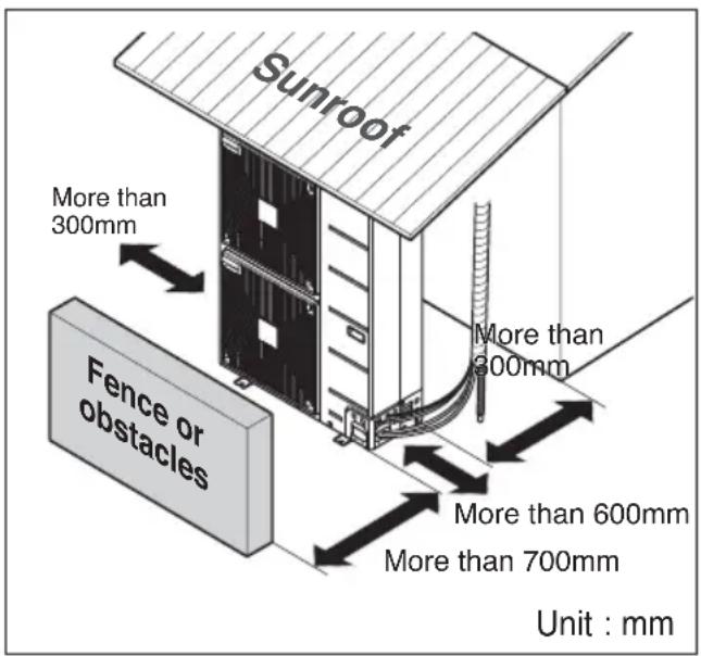
text_image
Sunroof More than 300mm Fence or obstacles More than 600mm More than 700mm Unit : mm2. Piping length and the elevation
FREE JOINT SINGLE OUTDOOR
| Model Capacity | Pipe Size Length | A(m) Elevation B(m) | Additional Refrigerant (g/m) | |||||
| Gas Liquid Standard | Max. Standard Max. | |||||||
| AUUQ18GH1 | 5kW ∅12.7( | 1/2) ∅6.35(1/4) | 7.5 30 5 15 | 20 | ||||
| AUUQ21GH1 | 6kW ∅12.7( | 1/2) ∅6.35(1/4) | 7.5 30 5 15 | 20 | ||||
| AUUQ24GH1 | 7kW ∅15.88 | (5/8) ∅9.52(3/8) | 7.5 50 5 30 | 40 | ||||
| AUUQ36GH1 | 10kW ∅1 | 5.88(5/8) ∅9. | 52(3/8) 7.5 50 5 30 | 40 | ||||
| AUUQ42GH1 | 12.5kW | ∅15.88(5/8) | ∅9.52(3/8) | 7.5 50 5 30 | 40 | |||
| AUUQ48GH1 | 13.4kW | ∅15.88(5/8) | ∅9.52(3/8) | 7.5 50 5 30 | 40 | |||
| AUUQ54GH1 | 15.8kW | ∅19.05(3/4) | ∅9.52(3/8) | 7.5 50 5 30 | 40 | |||
Ceiling Cassette
| Model Capacity | Pipe Size Length | A(m) Elevation B(m) | Additional Refrigerant (g/m) | |||||
| Gas Liquid Standard | Max. Standard | Max. | ||||||
| ATUQ18GPLE3 | 5kW ∅1 | 2.7(1/2) ∅6.35(1/4) 7.5 | 30 5 | 15 20 | ||||
| ATUQ21GPLE3 | 6kW ∅1 | 2.7(1/2) ∅6.35(1/4) 7.5 | 30 5 | 15 20 | ||||
| ATUQ24GNLE3 | 7kW ∅15.8 | 8(5/8) ∅9.52(3/8) 7.5 | 50 5 30 | 40 | ||||
| ATUQ36GMLE3 | 10kW | ∅15.88(5/8) | ∅9.52(3/8) 7.5 | 50 5 30 | 40 | |||
| ATUQ42GMLE3 | 12.5kW | ∅15.88(5/8) | ∅9.52(3/8) | 7.5 | 50 | 5 | 30 | 40 |
| ATUQ48GMLE3 | 13.4kW | ∅15.88(5/8) | ∅9.52(3/8) | 7.5 | 50 | 5 | 30 | 40 |
| ATUQ54GMLE3 | 15.8kW | ∅19.05(3/4) | ∅9.52(3/8) | 7.5 | 50 | 5 | 30 | 40 |
Ceiling Suspended Air conditioner
| Model Capacity | Pipe Size Length | A(m) Elevation B(m) | Additional Refrigerant (g/m) | ||||
| Gas Liquid Standard Max. Standard Max. | |||||||
| AVUQ18GJLA0 | 5kW ∅12.7(1/2) ∅6.35(1/4) 7.5 30 5 15 20 | ||||||
| AVUQ21GJLA0 | 6kW ∅12.7(1/2) ∅6.35(1/4) 7.5 30 5 15 20 | ||||||
| AVUQ24GJLA0 | 7kW ∅15.88(5/8) ∅9.52(3/8) 7.5 50 5 30 40 | ||||||
| AVUQ36GKLA0 | 10kW ∅15.88(5/8) ∅9.52(3/8) 7.5 50 5 30 40 | 40 | |||||
| AVUQ42GLLA0 | 12.5kW ∅15.88(5/8) ∅9.52(3/8) 7.5 50 5 30 40 | 40 | |||||
| AVUQ48GLLA0 | 13.4kW ∅15.88(5/8) ∅9.52(3/8) 7.5 50 5 30 40 | 40 | |||||
| AVUQ54GLLA0 | 15.8kW ∅19.05(3/4) ∅9.52(3/8) 7.5 50 5 30 40 | 40 | |||||
Ceiling Concealed Duct
Ceiling Concealed Duct – Low static
| Model | Capacity | Pipe Size | Length A(m) Elevation B(m) | Additional | ||||
| Gas | Liquid | Standard | Max. | Standard | Max. | (g/m) | ||
| ABUQ18GHLA0ABUQ18GL2A0 | 5kW | ∅12.7(1/2) | ∅6.35(1/4) | 7.5 | 30 | 5 | 15 | 20 |
| ABUQ21GHLA0ABUQ21GL2A0 | 6kW | ∅12.7(1/2) | ∅6.35(1/4) | 7.5 | 30 | 5 | 15 | 20 |
| ABUQ24GGLA0ABUQ24GL3A0 | 7kW | ∅15.88(5/8) | ∅9.52(3/8) | 7.5 | 50 | 5 | 30 | 40 |
| ABUQ36GGLA0 | 10kW | ∅15.88(5/8) | ∅9.52(3/8) | 7.5 | 50 | 5 | 30 | 40 |
| ABUQ42GRLA0 | 12.5kW | ∅15.88(5/8) | ∅9.52(3/8) | 7.5 | 50 | 5 | 30 | 40 |
| ABUQ48GRLA0 | 13.4kW | ∅15.88(5/8) | ∅9.52(3/8) | 7.5 | 50 | 5 | 30 | 40 |
| ABUQ54GRLA0 | 15.8kW | ∅19.05(3/4) | ∅9.52(3/8) | 7.5 | 50 | 5 | 30 | 40 |
If installed tube is shorter than 7.5 m, additional charging is not necessary. Additional Refrigerant = (A -7.5) x Additional refrigerant (g)

CAUTION:
- Capacity is based on standard length and maximum allowance length is on the basis of reliability.
- Improper refrigerant charge may result in abnormal cycle.
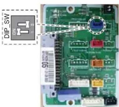
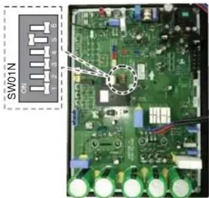
Night Silent Operation setting
- Open the Side panel or Top Cover of outdoor unit.
- Set the SW01N.

AUUQ18GH1 /AUUQ21GH1/ AUUQ24GH1 (ATUQ18GPLE3/ ATUQ21GPLE3/ ATUQ24GNLE3) (AVUQ18GJLA0/ AVUQ21GJLA0 / AVUQ24GJLA0) (ABUQ18GHLA0/ ABUQ21GHLA0/ ABUQ24GGLA0) (ABUQ18GL2A0/ ABUQ21GL2A0/ ABUQ24GL3A0)
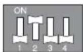
AUUQ36GH1 (ATUQ36GMLE3) (AVUQ36GKLA0) (ABUQ36GGLA0)
AUUQ42GH1/ AUUQ48GH1/ AUUQ54GH1 (ATUQ42GMLE3/ ATUQ48GMLE3/ ATUQ54GMLE3) (AVUQ42GLLA0/ AVUQ48GLLA0/ AVUQ54GLLA0) (ABUQ42GRLA0/ ABUQ48GRLA0/ ABUQ54GRLA0)
- Close the Side panel or Top Cover.
text_image
DIP_SW 55AUUQ18GH1 /AUUQ21GH1/ AUUQ24GH1 (ATUQ18GPLE3/ ATUQ21GPLE3/ ATUQ24GNLE3) (AVUQ18GJLA0/ AVUQ21GJLA0 / AVUQ24GJLA0) (ABUQ18GHLA0/ ABUQ21GHLA0/ ABUQ24GGLA0) (ABUQ18GL2A0/ ABUQ21GL2A0/ ABUQ24GL3A0)

text_image
SW01N ONAUUQ36GH1 (ATUQ36GMLE3) (AVUQ36GKLA0) (ABUQ36GGLA0)
text_image
SW01N CIN 7 2 3 4AUUQ42GH1/ AUUQ48GH1/ AUUQ54GH1 (ATUQ42GMLE3/ ATUQ48GMLE3/ ATUQ54GMLE3) (AVUQ42GLLA0/ AVUQ48GLLA0/ AVUQ54GLLA0) (ABUQ42GRLA0/ ABUQ48GRLA0/ ABUQ54GRLA0)
Wiring Connection
Electrical Wiring
Perform the electrical wiring work according to the electrical wiring connection.
- All wiring must comply with local requirements.
- Select a power source that is capable of supplying the current required by the air conditioner.
- Use a recognized ELCB(Electric Leakage Circuit Breaker) between the power source and the unit. A disconnection device to adequately disconnect all supply lines must be fitted.
- Model of circuit breaker recommended by authorized personnel only
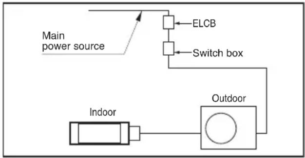
flowchart
graph TD
    A["Main power source"] --> B["Indoor"]
    B --> C["Outdoor"]
    C --> D["Switch box"]
    D --> E["ELCB"]
    E --> B
| Model Phase(∅) ELCB | ||
| AUUQ18GH1(ATUQ18GPLE3) (AVUQ18GJLA0) (ABUQ18GHLA0) (ABUQ18GL2A0) | 1 | 20A |
| AUUQ21GH1(ATUQ21GPLE3) (AVUQ21GJLA0) (ABUQ21GHLA0) (ABUQ21GL2A0) | 1 | |
| AUUQ24GH1(ATUQ24GNLE3) (AVUQ24GJLA0) (ABUQ24GGLA0) (ABUQ24GL3A0) | 1 25A | |
| AUUQ36GH1(ATUQ36GMLE3) (AVUQ36GKLA0)(ABUQ36GGLA0) | 1 30A | |
| AUUQ42GH1(ATUQ42GMLE3) (AVUQ42GLLA0) (ABUQ42GRLA0) | 1 | 40A |
| AUUQ48GH1(ATUQ48GMLE3) (AVUQ48GLLA0) (ABUQ48GRLA0) | 1 | |
| AUUQ54GH1(ATUQ54GMLE3) (AVUQ54GLLA0) (ABUQ54GRLA0) | 1 |
Connecting Cables between Indoor Unit and Outdoor Unit
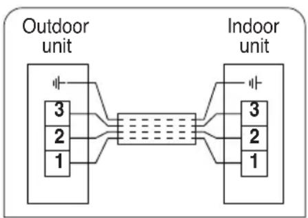
flowchart
graph LR
    A["Outdoor unit"] --> B["3"]
    A --> C["2"]
    A --> D["1"]
    B --> E["Indoor unit"]
    C --> E
    D --> E
    E --> F["3"]
    E --> G["2"]
    E --> H["1"]

CAUTION
The power cord connected to the outdoor unit should be complied with IEC 60245 or HD 22.4 S4 (This equipment shall be provided with a cord set complying with the national regulation.

text_image
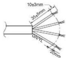
10±3mm 35±5mm GIVYL 20mm| Model | Phase(∅) | Area(mm2) |
| AUUQ18GH1/AUUQ21GH1/AUUQ24GH1(ATUQ18GPLE3/ATUQ21GPLE3/ATUQ24GNLE3)(AVUQ18GJLA0/AVUQ21GJLA0/AVUQ24GJLA0)(ABUQ18GHLA0/ABUQ21GHLA0/ABUQ24GGLA0)(ABUQ18GL2A0/ABUQ21GL2A0/ABUQ24GL3A0) | 1 | 2.5 |
| AUUQ36GH1/AUUQ42GH1/AUUQ48GH1/AUUQ54GH1(ATUQ36GMLE3/ATUQ42GMLE3/ATUQ48GMLE3/ATUQ54GMLE3)(AVNQ36GKLA0/AVNQ42GLLA0/AVNQ48GLLA0/AVNQ54GLLA0)(ABUQ36GGLA0/ABUQ42GRLA0/ABUQ48GRLA0/ABUQ54GRLA0) | 1 | 6 |
The connecting cable connected to the outdoor unit should be complied with IEC 60245 or HD 22.4 S4 (This equipment shall be provided with a cord set complying with the national regulation.)
text_image
10±3mm 35±5mm GNYL 20mmNORMAL
CROSS-SECTIONAL
AREA 0.75mm²
When the connection line between the indoor unit and outdoor unit is over 40m, connect the telecommunication line and power line separately.
If the supply cord is damaged, it must be replaced by a special cord or assembly available from the manufacturer of its service agent.
◆ Precautions when laying power wiring
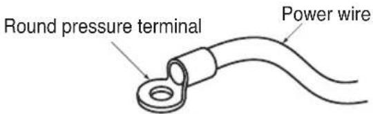
Use round pressure terminals for connections to the power terminal block.
text_image
Round pressure terminal Power wireWhen none are available, follow the instructions below.
- Do not connect wiring of different thicknesses to the power terminal block. (Slack in the power wiring may cause abnormal heat.)
- When connecting wiring which is the same thickness, do as shown in the figure below.

natural_image
Simple line drawing of a mechanical component with two circular holes and a ring, no text or symbols present.
natural_image
Simple line drawing of a container with two circular objects inside, no text or symbols present.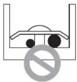
natural_image
Simple line drawing of a container with two circles inside, no text or symbols present- For wiring, use the designated power wire and connect firmly, then secure to prevent outside pressure being exerted on the terminal block.
- Use an appropriate screwdriver for tightening the terminal screws. A screwdriver with a small head will strip the head and make proper tightening impossible.
• Over-tightening the terminal screws may break them.
Connecting the cable to Outdoor Unit
- Remove the side panel for wiring connection.
- Use the cord clamp to fix the cord.
- Earthing work
- Connect the cable of diameter more to the earthing terminal provided in the control box and do earthing.

text_image
Connecting cable terminal Power cord terminal Cord clamp * Make sure the rubber bushes are properly used in knock-out holes after connecting main power.CAUTION:
- The circuit diagram is not subject to change without notice.
- Be sure to connect wires according to the wiring diagram.
- Connect the wires firmly, so that not to be pulled out easily.
- Connect the wires according to color codes by referring the wiring diagram.
CAUTION:
- The Power cord connected to the unit should be selected according to the following specifications.
Connecting Pipes
Preparation of Piping
Main cause of gas leakage is defect in flaring work. Carry out correct flaring work in the following procedure.
Cut the pipes and the cable.
- Use the accessory piping kit or the pipes purchased locally.
• Measure the distance between the indoor and the outdoor unit. - Cut the pipes a little longer than measured distance.
- Cut the cable 1.5m longer than the pipe length.
Burrs removal
- Completely remove all burrs from the cut cross section of pipe/tube.
- Put the end of the copper tube/pipe to downward direction as you remove burrs in order to avoid to let burrs drop in the tubing.
Putting nut on
- Remove flare nuts attached to indoor and outdoor units, than put them on pipe/tube having completed burr removal.
(Not possible to put them on after flaring work)
Flaring work
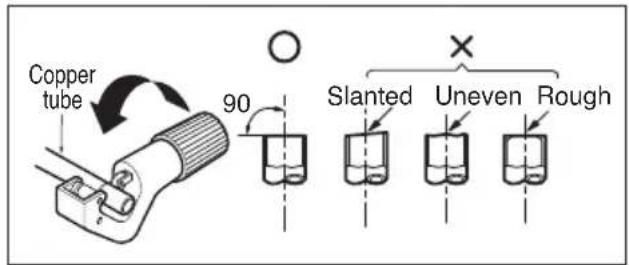
- Carry out flaring work using dedicated flaring tool for R-410A as shown below.
| Outside diameter "A" | ||
| mm inch | mm | |
| ∅6.35 1/4 | 1.1~1.3 | |
| ∅9.52 3/8 | 1.5~1.7 | |
| ∅12.7 1/2 | 1.6~1.8 | |
| ∅15.88 5/8 | 1.6~1.8 | |
| ∅19.05 | 3/4 | 1.9 |
Firmly hold copper tube in a bar(or die) as indicated dimension in the table above.
Check
• Compare the flared work with figure below.
- If flare is noted to be defective, cut off the flared section and do flaring work again.
text_image
Copper tube 90° Slanted Uneven Rough
text_image
Pipe Reamer Point down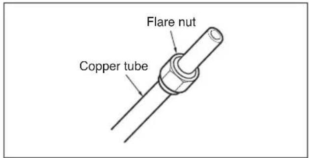
text_image
Flare nut Copper tube
text_image
Bar "Copper pipe "A" Handle Yoke Cone Clamp handle Red arrow mark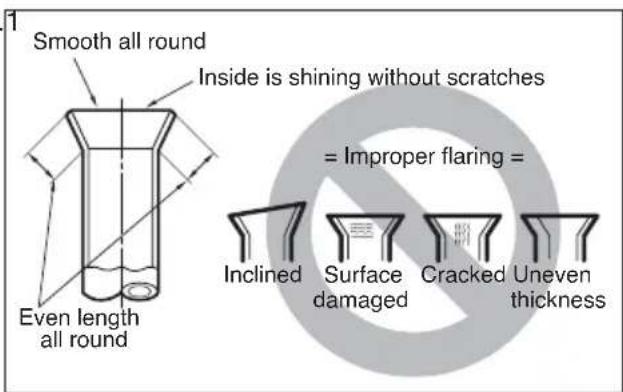
text_image
Smooth all round Inside is shining without scratches = Improper flaring = Even length all round Inclined Surface damaged Cracked Uneven thicknessConnecting the pipes to the Outdoor unit
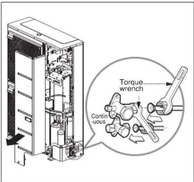
- Align the center of the piping and sufficiently tighten the flare nut by hand.
- Finally, tighten the flare nut with torque wrench until the wrench clicks.
- When tightening the flare nut with torque wrench, ensure the direction for tightening follows the arrow on the wrench.
| Outside diameter Torque | ||
| mm inch N | ·m | |
| ∅6.35 1/4 16±2 | ||
| ∅9.52 3/8 38±4 | ||
| ∅12.7 1/2 55±6 | ||
| ∅15.88 5/8 75±7 | ||
| ∅19.05 | 3/4 | 110±10 |
text_image
Torque wrench Contin -uous* When tighten the pipe, hold the haxagonal body.
Preventing foreign objects from entering
- Plug the pipe through-holes with putty or insulation material(procured locally) to stop up all gaps.

CAUTION:
Insects or small animals entering the outdoor unit may cause a short circuit in the electrical box.

text_image
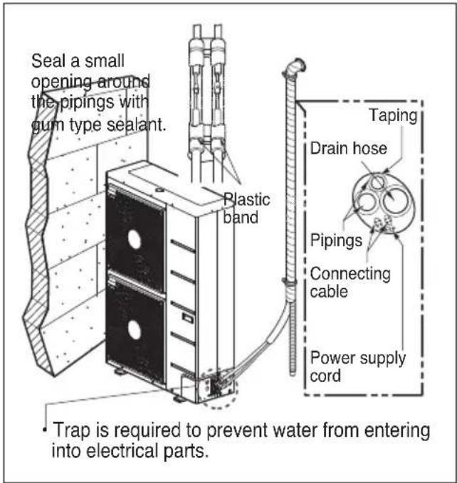
Drain hose Connecting wire Gas side piping Liquid side pipingForming the piping
Form the piping by wrapping the connecting portion of the indoor unit with insulation material and secure it with two kinds of vinyl tape.
- If you want to connect an additional drain hose, the end of the drain outlet should be routed above the ground. Secure the drain hose appropriately.
In cases where the outdoor unit is installed below the indoor unit perform the following.
- Tape the piping, drain hose and connecting cable from down to up.
- Secure the tapped piping along the exterior wall using saddle or equivalent.
In cases where the outdoor unit is installed above the indoor unit perform the following.
- Tape the piping and connecting cable from down to up.
- Secure the taped piping along the exterior wall. Form a trap to prevent water entering the room.
- Fix the piping onto the wall by saddle or equivalent.
text_image
Seal a small opening around the pipings with gum type sealant. Plastic band Taping Drain hose Pipings Connecting cable Power supply cord Trap is required to prevent water from entering into electrical parts.
text_image
Seal a small opening around the pipings with gum type sealant. Trap TrapLeakage test and Evacuation
Air and moisture remaining in the refrigerant system have undesirable effects as indicated below.
- Pressure in the system rises.
- Operating current rises.
- Cooling(or heating) efficiency drops.
- Moisture in the refrigerant circuit may freeze and block capillary tubing.
- Water may lead to corrosion of parts in the refrigeration system.
Therefore, the indoor/outdoor unit and connecting tube must be checked for leak tight, and vacuumed to remove incondensible gas and moisture in the system.
Preparation
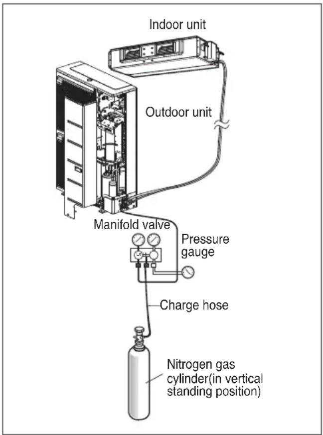
- Check that each tube(both liquid and gas side tubes) between the indoor and outdoor units have been properly connected and all wiring for the test run has been completed. Remove the service valve caps from both the gas and the liquid side on the outdoor unit. Check that both the liquid and the gas side service valves on the outdoor unit are kept closed at this stage.
Leakage test
- Connect the manifold valve(with pressure gauges) and dry nitrogen gas cylinder to this service port with charge hoses.

CAUTION: Be sure to use a manifold valve for leakage test.
If it is not available, use a stop valve for this purpose. The "Hi" knob of the manifold valve must always be kept close.
- Pressurize the system to no more than 3.0 Mpa with dry nitrogen gas and close the cylinder valve when the gauge reading reached 3.0 MPa Next, test for leaks with liquid soap.

CAUTION: To avoid nitrogen entering the refrigerant system in a liquid
state, the top of the cylinder must be higher than its bottom when you pressurize the system. Usually, the cylinder is used in a vertical standing position.
-
Do a leakage test of all joints of the tubing(both Indoor unit and outdoor unit) and both gas and liquid side service valves. Bubbles indicate a leak. Be sure to wipe off the soap with a clean cloth.
-
After the system is found to be free of leaks, relieve the nitrogen pressure by loosening the charge hose connector at the nitrogen cylinder. When the system pressure is reduced to normal, disconnect the hose from the cylinder.
text_image
Indoor unit Outdoor unit Manifold valve Pressure gauge Charge hose Nitrogen gas cylinder(in vertical standing position)Evacuation
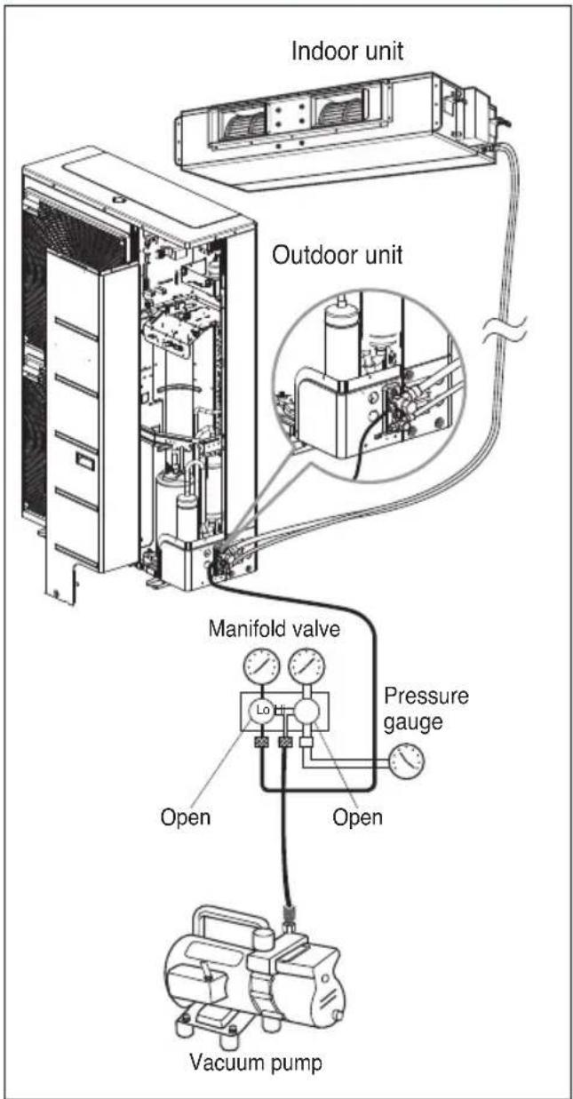
- Connect the charge hose end described in the preceding steps to the vacuum pump to evacuate the tubing and indoor unit.
Confirm the "Lo and Hi" knob of the manifold valve is open. Then, run the vacuum pump.
The operation time for evacuation varies with tubing length and capacity of the pump. The following table shows the time required for evacuation.
| Required time for evacuation when 30 gal/h vacuum pump is used | |
| If tubing length is less than 10 m(33 ft) | If tubing length is longer than 10 m(33 ft) |
| 30 min. or more 60 min. or more | |
| 0.07 kPa or less | |
- When the desired vacuum is reached, close the "Lo and Hi" knob of the manifold valve and stop the vacuum pump.
Finishing the job
-
With a service valve wrench, turn the valve stem of liquid side valve counter-clockwise to fully open the valve.
-
Turn the valve stem of gas side valve counterclockwise to fully open the valve.
-
Loosen the charge hose connected to the gas side service port slightly to release the pressure, then remove the hose.
-
Replace the flare nut and its bonnet on the gas side service port and fasten the flare nut securely with an adjustable wrench. This process is very important to prevent leakage from the system.
-
Replace the valve caps at both gas and liquid side service valves and fasten them tight.
This completes air purging with a vacuum pump.
The air conditioner is now ready to test run.
text_image
Indoor unit Outdoor unit Manifold valve Pressure gauge Open Open Vacuum pumpTest running
1. PRECAUTIONS IN TEST RUNNING
- The initial power supply must provide at least 90% of the rated voltage. Otherwise, the air conditioner should not be operated.

CAUTION
① For test run, carry out the cooling operation firstly even during heating season. If heating operation is carried out firstly, it leads to the trouble of compressor. Then attention must be paid.
② Carry out the test run more than 5 minutes without fail. (Test run will be cancelled 18 minutes later automatically)
- The test run is started by pressing the room temperature checking button and down timer button for 3 seconds at the same time.
- To cancel the test run, press any button.
CHECK THE FOLLOWING ITEMS WHEN INSTALLATION IS COMPLETE
- After completing work, be sure to measure and record trial run properties, and store measured data, etc.
- Measuring items are room temperature, outside temperature, suction temperature, blow out temperature, wind velocity, wind volume, voltage, current, presence of abnormal vibration and noise, operating pressure, piping temperature, compressive pressure.
- As to the structure and appearance, check following items.
□ Is the circulation of air adequate?
□ Is the remote controller switch operated?
□ Is the draining smooth?
□ Is there any faulty wiring?
□ Is the heat insulation complete (refrigerant and drain piping)?
□ Are not terminal screws loosened?
□ Is there any leakage of refrigerant?
M4.....118N·cm{12kgf·cm} M5.....196N ·cm{20kgf·cm}
M6.....245N·cm{25kgf·cm} M8.....588N ·cm{60kgf·cm}
2. Connection of power supply
- Connect the power supply cord to the independent power supply.
- Circuit breaker is required.
- Operate the unit for fifteen minutes or more.
3. Evaluation of the performance
- Measure the temperature of the intake and discharge air.
- Ensure the difference between the intake temperature and the discharge one is more than 8^ C (Cooling) or reversely (Heating).

CAUTION: After the confirmation of the above conditions, prepare the wiring as follows:
1) Never fail to have an individual power specialized for the air conditioner. As for the method of wiring, be guided by the circuit diagram pasted on the inside of control box cover.
2) Provide a circuit breaker switch between power source and the unit.
3) The screw which fasten the wiring in the casing of electrical fittings are liable to come loose from vibrations to which the unit is subjected during the course of transportation. Check them and make sure that they are all tightly fastened. (If they are loose, it could give rise to burn-out of the wires.)
4) Specification of power source
5) Confirm that electrical capacity is sufficient.
6) Be sure that the starting voltage is maintained at more than 90 percent of the rated voltage marked on the name plate.
7) Confirm that the cable thickness is as specified in the power sources specification.
(Particularly note the relation between cable length and thickness.)
8) Never fail to equip a leakage breaker where it is wet or moist.
9) The following troubles would be caused by voltage drop-down.
- Vibration of a magnetic switch, damage on the contact point there of fuse breaking, disturbance to the normal function of a overload protection device.
- Proper starting power is not given to the compressor.
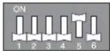
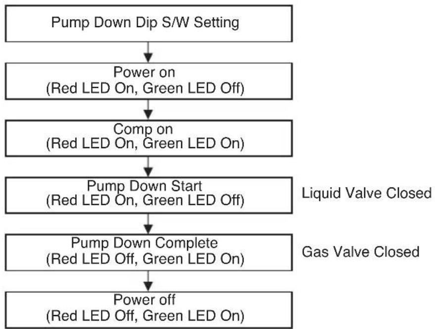
Function
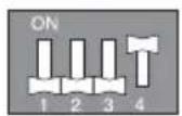
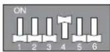
Forced Cooling Operation
- Adding the refrigerant in winter.
Setting Procedure
1) Set the Dip Switch as follow after shutting the power source down.

AUUQ18GH1 /AUUQ21GH1/ AUUQ24GH1 (ATUQ18GPLE3/ ATUQ21GPLE3/ ATUQ24GNLE3) (AVUQ18GJLA0/ AVUQ21GJLA0 / AVUQ24GJLA0) (ABUQ18GHLA0/ ABUQ21GHLA0/ ABUQ24GGLA0) (ABUQ18GL2A0/ ABUQ21GL2A0/ ABUQ24GL3A0)
AUUQ36GH1 (ATUQ36GMLE3) (AVUQ36GKLA0) (ABUQ36GGLA0)
AUUQ42GH1/ AUUQ48GH1/ AUUQ54GH1 (ATUQ42GMLE3/ ATUQ48GMLE3/ ATUQ54GMLE3) (AVUQ42GLLA0/ AVUQ48GLLA0/ AVUQ54GLLA0) (ABUQ42GRLA0/ ABUQ48GRLA0/ ABUQ54GRLA0)
2) Reset the power.
3) Red LED and Green LED of PCB lights during work. (The indoor unit is operated by force.)
4) If operation is done, Red LED will be turned off.
If operation is not done normally, Red LED will blink.
5) Close the Liquid valve only after green LED turned off (7 minutes from the start of the machine). Then close the gas valve after Green LED on.

WARNING:
- When the green LED of PCB is on, compressor is going to be off because of low pressure.
- You should return the Dip Switch to operate normally after finishing the operation.
- Improper Pump down will lead to product turn off along with LED (green &red) off with in 20 minutes from the initial start.
flowchart
graph TD
    A["Pump Down Dip S/W Setting"] --> B["Power on (Red LED On, Green LED Off)"]
    B --> C["Comp on (Red LED On, Green LED On)"]
    C --> D["Pump Down Start (Red LED On, Green LED Off)"]
    D --> E["Pump Down Complete (Red LED Off, Green LED On)"]
    E --> F["Power off (Red LED Off, Green LED On)"]
    style A fill:#f9f,stroke:#333
    style B fill:#ccf,stroke:#333
    style C fill:#ccf,stroke:#333
    style D fill:#ccf,stroke:#333
    style E fill:#ccf,stroke:#333
    style F fill:#ccf,stroke:#333
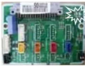
Self-diagnosis Function
Error Indicator (Outdoor)

text_image
LED01G (RED) 1 Sec. 1 Sec. 1 Sec. 2 Times2 Times2 Time LED02G (GREEN) 1 Time 1 Time 1 Time 2 Sec. 2 Sec.Outdoor Error
Ex) Error 21 (DC Peach)
natural_image
Close-up of a green printed circuit board with various electronic components (no visible text or symbols)natural_image
Close-up of a green printed circuit board with electronic components and a white starburst overlay (no readable text or symbols)AUUQ36GH1
(ATUQ36GMLE3)
(AVUQ36GKLA0)
(ABUQ36GGLA0)

natural_image
Close-up of a green printed circuit board with electronic components and a starburst symbol (no readable text or symbols)AUUQ42GH1/ AUUQ48GH1/ AUUQ54GH1
(ATUQ42GMLE3/ATUQ48GMLE3/ATUQ54GMLE3)
(AVUQ42GLLA0/AVUQ48GLLA0/AVUQ54GLLA0)
(ABUQ42GRLA0/ ABUQ48GRLA0/ ABUQ54GRLA0)
| Error Code | Description | LED 1(Red) | LED 2(Green) | Indoor status |
| 21 DC Peak(IPM Fault) | 2times ⬆ | 1time ⬆ | OFF | |
| 22 Max. CT(CT2) | 2times ⬆ 2times | OFF | ||
| 23 DC Link Low Volt. | 2times ⬆ 3times | OFF | ||
| 24 Pressure switch/Heater Sink. | 2times ⬆ 4times | OFF | ||
| 26 DC Comp Position Error | 2times ⬆ 6times | OFF | ||
| 27 PFC Fault Error | 2times ⬆ 7times | OFF | ||
| 29 Comp Over Current | 2times ⬆ 9times | OFF | ||
| 32 D-Pipe High(Inv.) | 3times ⬆ 2times | OFF | ||
| 40 CT Sensor(Open/Short) | 4times ⬆ 0 OFF | |||
| 41 Inv. D-Pipe Th Error(Open/Short) | 4times ⬆ | 1time ⬆ | OFF | |
| 43 High Pressure Sensor(Open/Short) | 4times ⬆ 3times | OFF | ||
| 44 Outdoor air Th Error(Open/Short) | 4times ⬆ 4times | OFF | ||
| 45 Cond. Middle Pipe Th Error(Open/Short) | 4times ⬆ 5times | OFF | ||
| 51 Capacity over | 5times ⬆ 1times | OFF | ||
| 53 Communication Error(Indoor ↔ Outdoor) | 5times ⬆ 3times | OFF | ||
| 60 EEPROM Error(Outdoor) | 6times ⬆ 0 OFF | |||
| 61 Cond. Middle Pipe High | 6times ⬆ 1times | OFF | ||
| 62 Heatsink Error(High) | 6times ⬆ 2times | OFF | ||
| 65 Heatsink Th Error(Open/Short) | 6times ⬆ 5times | OFF | ||
| 67 BLDC motor fan lock(Outdoor) | 6times ⬆ 7times | OFF | ||
If abnormal voltage is supplied, the protection circuits will turn off the product in order to prevent the component damage. The product will automatically restart after 3 minutes.
Installation Guide at the Seaside

CAUTION:
- Air conditioners should not be installed in areas where corrosive gases, such as acid or alkaline gas, are produced.
- Do not install the product where it could be exposed to sea wind (salty wind) directly. It can result corrosion on the product. Corrosion, particularly on the condenser and evaporator fins, could cause product malfunction or inefficient performance.
- If outdoor unit is installed close to the seaside, it should avoid direct exposure to the sea wind. Otherwise it needs additional anticorrosion treatment on the heat exchanger.
Selecting the location(Outdoor Unit)
1) If the outdoor unit is to be installed close to the seaside, direct exposure to the sea wind should be avoided. Install the outdoor unit on the opposite side of the sea wind direction.
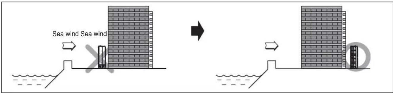
text_image
Sea wind Sea wind2) In case, to install the outdoor unit on the seaside, set up a windbreak not to be exposed to the sea wind.
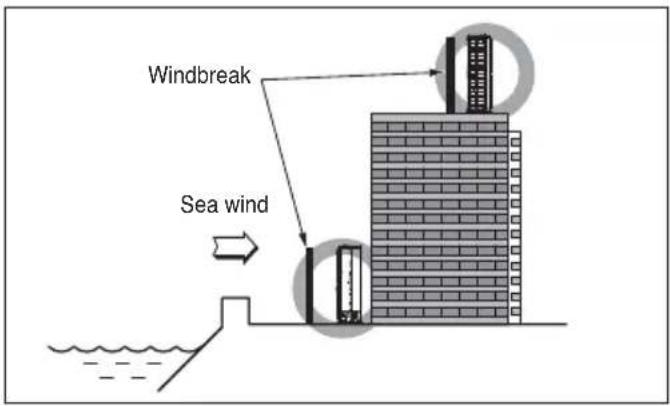
text_image
Windbreak Sea wind3) Select a well-drained place.
- It should be strong enough like concrete to prevent the sea wind from the sea.
- The height and width should be more than 150% of the outdoor unit.
- It should be keep more than 70 cm of space between outdoor unit and the windbreak for easy air flow.
- Periodic (more than once/year) cleaning of the dust or salt particles stuck on the heat exchanger by using water

LG
Life's Good