
DX3-PPEDTW - Watering Irritrol - Free user manual and instructions
Find the device manual for free DX3-PPEDTW Irritrol in PDF.

| Product Type | Irrigation Controller |
| Brand | Irritrol |
| Model | DX3-PPEDTW |
| Cabinet Dimensions (Wall Mount) | 11 in (W) x 16 in (H) x 5.625 in (D) |
| Operating Temperature Range | +14°F to +140°F (-10°C to +60°C) |
| Power Input | 120 VAC (typical) |
| Maximum Stations (Conventional) | 96 |
| Maximum Stations (Two-Wire) | 200 |
| Display | 4.4-inch QVGA monochrome LCD, 320x240 pixels |
| Programs | 16 conventional programs |
| Start Times per Program | Up to 12 |
| Communication Options | Ethernet, WiFi, Cellular, UHF Radio, Serial |
| Flow Monitoring | Up to 3 flow sensors, with upper/lower limit alerts |
| Current Monitoring | Per station, with upper/lower limit alerts |
| Lightning Protection | Up to 18 kV |
| Warranty | 5 years (manufacturer's warranty) |
Frequently Asked Questions - DX3-PPEDTW Irritrol
User questions about DX3-PPEDTW Irritrol
0 question about this device. Answer the ones you know or ask your own.
Ask a new question about this device
Download the instructions for your Watering in PDF format for free! Find your manual DX3-PPEDTW - Irritrol and take your electronic device back in hand. On this page are published all the documents necessary for the use of your device. DX3-PPEDTW by Irritrol.
USER MANUAL DX3-PPEDTW Irritrol
About This Manual....5
Getting Help....6
Chapter 2: Overview....7
The Faceplate....7
The Buttons 8
The LEDs....9
The Screen 9
Menu Navigation ....10
Chapter 3: Quick Start .... 11
Setting Current Date and Time 12
Creating a New Irrigation Schedule 12
Program Start Time....13
Water Days....14
Station Run Times....15
Program Hold 16
% Adjust 17
Manual Operation....18
Chapter 4: Setup....21
Flow 22
Learn Flow/Current....25
Omit by Date....26
Communication....27
Current Checks....30
Time/Date....31
Firmware Update....31
FLOW MAX....32
Station Count....32
Master Valves & Pumps....33
Program Decoder 34
Chapter 5: Program Entry 37
Start Times....38
Water Days....38
Run Times....39
Quick Stations....39
Program Hold 40
OPT INs....41
Erase/Reset....43
% Adjust 43
Backup Programs 10 & 11....44
Chapter 6: Stations....45
Flow 45
Current....46
Cycle & Soak 47
Chapter 7: Reports and Diagnostics....49
Reports....49
Diagnostics - General....51
Diagnostics - Communications ....53
Communications....55
Chapter 8: Alerts....57
Anaylzing an Alert....58
Alerts and Corrective Action 60
Chapter 9: Rain Hold....65
Chapter 10: Manual Operation ...... 67
Station....68
Simultaneous....69
Sequence 70
Program....71
Chapter 11: Review 73
Overview 73
System Review....74
Program Review....75
Station Review....77
Flow Review....78
About....78
Weather Review 79
Chapter 12: Troubleshooting....81
Communications Wiring Issues (Satellite to Satellite) 81
Directory of Flow Chart Diagnostic Problems 84
Control Devices (Rain Sensors, Freeze sensors, Etc.)....99
Appendix A: Specifications 101
Appendix B: Flow Sensors 103
Flow Sensor Installation Instructions....104
Flow Sensor Overview....104
Flow Sensor Offset and K Values 105
Flow Limit Checking....106
Flow Limit Violations ....109
Appendix C: Current Alarms Within a Conventionally Wired DX3 System 112
Appendix D: Setting Up a FLOW MAX System...... 119
Overview 120
Physical Configuration 122
Flow Max Setup Procedure....125
Flow Max Flow Limits 126
Satellite Controllers....127
Flow Max Worksheet....129
Flow Max Diagnostic Tools....132
Flow Max Warnings and Exception Conditions....134
Appendix E:
Hardwired Communication Troubleshooting.... 135
Normal Operating Behavior: 136
Inspecting Field Wiring:....139
Glossary 141
Index....147
FCC Notice - Electromagnetic Compatibility....149
RAIN MASTER LIMITED WARRANTY....150
California Proposition 65 Warning Information....151
Notes....153
Chapter 1: Introduction
Thank you for supporting Rain Master ^® and the Laguna ^™ / DX3 ^™ central control platform. As the long-awaited successor to the Evolution ^™ DX2 controller, we hope the DX3 will exceed your expectations and contribute to Rain Master's legacy of innovation and service.
About the Controller
Rain Master believes in minimizing waste by maximizing water application efficiency. The DX3 provides precise control of irrigation delivery systems through a flexible network that could fit almost any application. DX3 will work with your Rain Master Laguna software to monitor, adjust, and report on irrigation schedules to your technical comfort level.
Hardware Features
Capacity:
- Up to 96 stations per satellite in conventional configurations, 200 stations per controller in two-wire (TWICE™) configurations.
- Up to 48 conventional stations and 152 two-wire stations in our hybrid models (for TWICE two-wire conversion projects).
- Three dedicated master valve (MV) outputs, either normally closed or normally open.
- Two auxiliary 24VAC relays for pumps, lights, etc.
- Three inputs to connect flow sensors/meters and three inputs for rain, wind, and ET pulsed data devices. Note that these devices would be independent of the optional LAGUNA wireless weather solutions, which are all wireless.
- Three alarm inputs
- An expansive, 4.4" LCD back-lit display with rapid menu navigation and "digital ink" for high visibility in the sun.
- Integrated cabinet access lighting or “fridge light” and pivoting brackets for improved setup and service access (select models).
- Transparent, custom – fit plastic covers for all circuit boards for added protection against the elements and pests.
- Many system communication options, including cellular, UHF Radio, Ethernet-to-Radio, Ethernet, Hardwire, WiFi and more!
• Lightning protection up to 18kV. - Integrated amperage meter to enhance internal diagnostics and troubleshooting
- Up to 21 simultaneous station-related operations (sixteen valves, three MVs, and two pumps).
Scheduling and Programming Features
• 16 conventional programs with up to 12 start times per program
- Exclusive DX series Individual Station Control (ISC™): Treat every active station as an individual program
- Customizable scheduling calendar with up to 48 exclusion days
• Programmable MV and Station Delay
- Global water window (Manual can override)
Maintenance and Alarm Diagnostic Capabilities
- Flow monitoring. Overflow, underflow, unscheduled flow, and catastrophic occurrence monitoring and reporting.
- Electrical alarm with station shutdown and program advance for station/s over current, shorts, damaged wires, and/or faulty solenoids.
• Power outage restoration alarms.
• LED indication for station outputs. - Electrical self diagnostic test to identify specific station output faults.
- Manual test mode that can advance stations while displaying valve electrical current and station flow data.
Communication Features
The DX3 is capable of communicating with the Central computer over a variety of communication technologies.
| Cellular Optional accessory for Central to sub-master communication. |
| WiFi “Short range” standard WiFi to Central, sold as an optional accessory. |
| Ethernet Standard on all DX3 systems. |
| Ethernet-to-Radio Sold as an optional stand-alone accessory. |
| UHF Radio Sold as an optional stand-alone or embedded accessory. |
| Serial cable Serial communication to Central or Diagnostic PC. |
About This Manual
This manual is divided into five sections:
- A Quick Start tutorial on quickly getting an irrigation program going and other common irrigation tasks.
- A Reference section, with every command explained.
- A Maintenance and Troubleshooting section to help you, the operator, resolve any problems or questions you might have quickly and effectively.
- Appendices
• A: Specification
• B: Flow Meters
• C: Current Monitoring
• D: Flow Max
- A glossary and index.
Icons Explained


BUTTON


001
A note to clarify.
Important
Warning! Risk of electric shock
Press the specified button.
Rotate the Control Dial.
Press the Control Dial.
The box indicates which field can be changed.
When the value flashes, it is ready to be changed.
Adjustable Fields.


to switch between the different fields.

to switch between values in date, time, and run time fields.

option 1 option 2
Press the Control Dial to adjust values in this field.
There are typically two values in a field like this.

option 1 option 2 option 3
Change values in this field with the Control Dial.
001

For numeric fields only.
Change number values with the Control Dial.
Getting Help
Rain Master strives to build safe, durable, and easy to use product. If, however, you encounter a problem that is not easily resolved with the troubleshooting solutions offered in "Chapter 12: Troubleshooting" on page 81, please contact an authorized Rain Master product expert for assistance via phone or email.
U.S./Canada:
Phone: 1-800-777-1477 (7:30 am–4 pm, M–F, PT)
E-mail: irrigationsupport@irritrol.com
Chapter 2: Overview
Because not all irrigation applications are identical, the DX3 controller has been designed to allow users to establish a wide variety of individual programmable options. These options include changing global settings, program configurations, station settings, communication type and sensor shutdown criteria.
The Faceplate

The Buttons
 | Control DialRotate to switch between fields on a screen and change values within those fields.Press to enter a desired field and to save the value. |
 | Left, Right, and Back buttonsTo navigate screen and menu selections. |
 | “A” buttonTo... |
 | “B” buttonTo... |
 | Command buttonTo execute the on-screen command closest to that particular command button. |
 | All StopTo stop all current irrigation activity. |
 | ManualTo manually operate the controller. |
 | DashboardTo return the controller to the “Dashboard” screen. |
 | ReviewTo review irrigation program settings. |
The LEDs
The DX3 has three LEDs beneath the main LCD screen. Each LED illuminates for a specific reason:

| Rain Off(blue) | Illuminated when the Rain Off command is active.All irrigation activity is suspended when this light is on. |
| Alert(red) | Illuminated when a user alert for the operator has been triggered, such as after a loss of power or loss of pressure.Alerts must be manually cleared in the Alert submenu. |
| Irrigation(green, blue, no illumination) | Illuminates green when irrigation is actively in operation.Illuminates blue when no valid program is scheduled to irrigate today.No illumination when a valid program is scheduled to irrigate today, but is not actively irrigating. |
The Screen
The Liquid Crystal Display (LCD) screen on the DX3 controller is 4.4" QVGA monochrome display screen capable of 320 x 240 pixels.

The main menu
On both sides of the screen are three command buttons for quick and easy execution of the button's assigned command.
Menu Navigation
Navigating menus and executing commands in the DX3 is easy with the various buttons and the Control Dial.
To navigate the typical DX3 screen, we will use the below as an example.

flowchart
graph TD
    A["Press and to move between the different "top" screens."] --> B["Setup Flow Sensors WED 5:43:40 PM"]
    B --> C["Sensor 1 | Sensor 2 | Sensor 3"]
    C --> D["Sensor 1 Type FS-B100"]
    D --> E["Sensor Name ?"]
    E --> F["K Factor 00109"]
    F --> G["Offset 0027"]
    G --> H["Include In Total Flow YES"]
    H --> I["Connection Type Decoder"]
    I --> J["Number fields must be adjusted by ."]
Navigating and Executing
- to navigate between adjustable fields.
The "active" field will have a black box around it.
-
to enter the "active" field.
-
to adjust the value.

Some fields have preset options like "Custom" vs. "Data Ind". Other fields are numeric and are adjusted incrementally.
-
to set desired option.
-
Repeat steps 1 - 4 for all adjustable fields.
Chapter 3: Quick Start
This chapter is a step-by-step tutorial for rapid and basic controller setup. For the demonstration, we will set up an irrigation schedule with 2 start times: 6:15am and 8pm daily, 1 cycle at 10 minutes per station.

The Quick Start guide does not address advanced features such as sensors (Chapter 4), flow (Appendix B), ET, or FLOWMAX (Appendix C).
Before we can program an irrigation schedule, we must enter the date and time.
To get to the Setup screen from the Dashboard, press the Control dial or any one of the Command buttons


The Setup Screen

Setting Current Date and Time


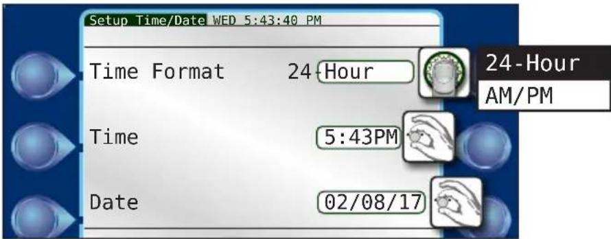
3) Switch between the 3 time/date fields.
4) Using the navigation techniques from page 14, adjust fields as necessary.
5) Repeat as necessary for the other fields. When done, press

Creating a New Irrigation Schedule
Now that the date and time are set, we can set up the irrigation schedule.
Program Start Time
1)

pnam
2)

Program 1

3)
Start
Times

It is possible to have 12 start times per program.
4) and to adjust the first start time to 6:15am.
5) and to adjust Start Time 2 to 8:00pm.

Press 'A' to clear start times.

Start times set!
6) When done, press

Water Days

1) Water Days

2) Enter Schedule Type field. 3) Change to desired
schedule. I chose 31-DAY.

4) Set Schedule Type. 5) to Alternate.
6) Set Alternate.
Alternate days are active.
Chapter 3: Quick Start
Station Run Times
1) Run Times

2) Enter Station 1 hours field.
Our run time will only be for ten minutes, so we can switch to the minutes field.

3) Switch to minutes field. 4) Adjust desired run time in minutes.
5) Set Station 1 run time. 6) Switch to next Station field.
7) Repeat steps 2-6 for as necessary for as many stations as desired.

Press 'A' to clear run times.

Stations 1 - 6 set with ten minute run-times.
Program Hold
A storm is coming! Irrigation will not be needed for a few days. Let's activate a Program Hold on Program 1.
1) Program
2) Program 1

3) Program Hold

4) Enter Set Day(s) field. 5) Change to desired days. 4 days to dry out.
The weather overall is getting cooler.
Let us decrease the overall amount of irrigation for this program.
1)

Program
2)

Program 1

3)

to the Page 2 Program 1 Menu screen.

4)

djust

5)

% Adjust field. 6) Change to desired %. I reduced to 50%.
7)

Set value.
8) When done, press


Above, we set our run times to ten minutes per station.
A 50% runtime would therefore cut that in half, to five minutes.
Manual Operation
The grass is a little dry. Let us run a manual program operation at 10pm to help keep that grass green.
1) Press the Hand Manual button.

2) Program

3) Enter Program# field. 4) Select program to run. I chose 1.
5) Set Program value. 6) Navigate to Start Time field.
7) Enter Start Time field. Hours field will flash. 8) Change hour value to 10.
9) Switch to minute field. 10) Switch to AM/PM field.
13) When done, to the Activate field and . The operation will execute this evening and save the grass.
Reference
The rest of this manual is dedicated to explaining every function and command available to the DX3 controller, organized by the Main Menu categories below.

| Command Chapter | |
| Setup 4 | |
| Program 5 | |
| Stations 6 | |
| Reports & Diagnostics 7 | |
| Alerts 8 | |
| Rain Hold 9 | |
Chapter 4: Setup
This chapter describes every function within the Setup section of the controller.

All step-by-step directions are started from the above Setup screen.

Press or to get to Page 2 and/or 3 of the Setup options.

Second screen of Setup options
Flow

Flow Sensors
Flow Sensors can calculate and report the amount of water, in gallons per minute, travelling through a pipe. For a complete explanation on flow sensors, including basic instructions on how to install a flow sensor, please see Appendix B: Flow Sensors.
- Flow
- Flow Sensors
- to navigate to field to set. Fields that can be changed are: Sensor Type, K Factor, Offset, and Include In Total Flow calculations or not.


Include in Total Flow: If checked No, all flow sensor data will be ignored for the selected sensor, including any connected satellites in a FLOWMAX group that utilize sensor 1.
Type: Select from Custom, FS-B100, FS-B125, FS-B150, FS-B200, FS-B250, FS-B15, FS-10, FS-15, FS-20, FS-30, FS-40, FS-60, FS-150, FS-200, FS-300, and FS-400.
K-factor: The number of pulses generated in a flow meter used to calculate volumetric throughput.
Offset: A number used to compensate flow calculations when there is a change in temperature and/or pressure.

The K-Factor and offset numbers are automatically adjusted for all available flow sensors except the Custom setting. See Appendix B: Flow Meters for K-factor and Offset numbers for common flow meters with their respective 'K' and Offset settings.
Connection Type: Set Local for conventionally-wired flow sensors and Decoder for a 2-wire flow decoder.
- to enter that field.
- to switch between options.
- to set desired option.
Press or to the next sensor.

Flow Options
Flow Options establishes flow limits to aid in the detection of possible flow problems.
1. Flow Options

Limits
Monthly Limit: The number, in total gallons, that the irrigation system should not exceed per month. If it does, the DX3 controller will either generate an alert (and keep watering) or simply stop watering until a new month begins. Watering can also be resumed by increasing the monthly limit.
Main Line Limit: The number, in gallons per minute, the flow of the main line shall not exceed. If the calculated flow ever does exceed this number, an alert will be triggered condemning all irrigation until cleared. The number should be set to a value higher than the flow if all simultaneous stations (six) are “on” but lower than if there is a main line break.
Unscheduled Limit: During periods of no programmed irrigation activity or no manually activated irrigation, the flow in a system should be zero. The Unscheduled Limit number, then, is the number in gallons per minute set to trip an alert if flow is detected during these times of inactivity, condemning all automatic irrigation until cleared.
Unscheduled flow conditions may be due to broken water lines, defective valves, faulty solenoids, and/or more.
Flow Check Delay: When a valve is activated, the initial flow rate may be significantly higher than the valve's “steady” state. This could be due to drainage of water lines, waiting for pump water, or other. The initial high flow rate could therefore trigger many unwanted and premature alerts. This Flow Check Delay delays the calculation of flow for a period of two to nine minutes to allow the flow to stabilize.
To set this number accurately, observe which station takes the longest time for its GPM rate to stabilize. Round this time period to the next minute and use that rounded value as the Flow Check Delay value

Press or to get to "Monitoring" Flow Options.
Monitoring Flow
Once the station flow limits have been established, the flow limit checking (upper and lower limits) may be enabled or disabled. When upper limits have been enabled, all station upper limits will be enforced on an individual station basis. When lower limits have been enabled, all station lower limits will be enforced on an individual station basis.

The default is disabled, meaning no limit checking is performed. However, the GPM flow and total monthly flow are still calculated. Monthly limit, main line limit, unscheduled flow, and flow check delay are always enforced regardless of the flow limit monitoring settings.
To Enable Max and/or Min Flow Limit Monitoring:
1) to switch between the check boxes.
2) to turn on or off desired option.

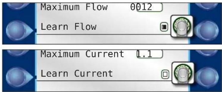
Learn Flow/Current
For the DX3 controller to issue meaningful alerts when there is a flow or current problem, the proper flow and current rates must be “learned” by the system. The Learn Flow/Current command therefore teaches the DX3 system the nominal (ideal) current and flow settings to each valve and station. One would typically activate the Learn command for either a new system or when a when a new flow meter has been installed.

The Learn Flow/Current command consists of three screens:
Current %'s: Setup the Nominal Current limits. Use the Control Dial to switch between and adjust the Upper and Lower Limit fields. Recommended value for Upper Limit and Lower Limit is 30% for both.
Flow %'s: Setup the Nominal Flow limits. Use the Control Dial to switch between and adjust the Upper and Lower Limit fields. Recommended value for Upper Limit and Lower Limit is 20% for both.
Use the Control Dial to activate the Learn Flow/Current command, triggering the 3rd screen above.

If the “All Satellites” check box is checked, the learn function will be performed on the submaster and all connected satellites.
On the 3rd screen, two things:

If your new system does not have a flow meter installed, be sure the Include Flow checkbox is blank.

If you are running the Learn Flow/Current command due to a new flow meter being installed, be sure the Include Current checkbox is blank.
Omit by Date
The DX3 allows up to 48 days to be excluded from irrigation per year.

Dates can be excluded in the following ways:
annual - the exclusion occurs once per year, every year one-time - the exclusion occurs only on the date specified disabled - the excluded date is not excluded
Steps
1) Omit by Date
2) to navigate to field to set. Fields that can be changed are: month, date, year (if not "Annual"), and the omit type.
3) to enter selected field.
4) to switch between options.
5) to set desired option.
6) Repeat steps 1 - 4 for all days to omit.

Press out to get to the next group of Omit Days.
Communication
Submaster
If the Submaster option is active, that means the DX3 controller has a direct link to the Central computer. The controller can communicate with the Central in any one of six methods:

• Raveon M8 (UHF radio)
- Ethernet
- Wifi
- Serial
• Digi Cellular
- Other
The Submaster Address can be any number between 0 and 999. If you were to have more than one DX3 controller as a Submaster attached to any one Central computer, be sure they have different Submaster addresses.
Use the Control Dial to activate, select a communication method, and assign an address for these fields.

Press off to get to "Ethernet" screen.
Cloud Connect
Cloud connect provides a method for remotely accessing the irrigation control. The user has an option of using cloud connect via Ethernet, Cellular or WiFi.
Cloud connect is mandatory for cellular communication to the Central and optional for WiFi or Ethernet communication to the Central.
Ethernet
If the Ethernet or Wifi communication method is selected in the previous screen, it might be necessary to configure the DX3's TCP/IP settings.
If your network uses Dynamic Host Configuration Protocol (DHCP) to dynamically assign IP addresses, then simply leave DHCP Client set to YES.
If, however, your networked devices require static IP addresses, change DHCP Client field to NO and, using the Control Dial, enter the appropriate IP address information. Contact your network administrator for the correct configuration information.


LAGUNA Port defaults to 10001. If separate WLAN ports are desired, they must use a unique LAGUNA Port (a rare-use case).
WiFi
The WiFi menu is used to select the wireless network to connect to (SSID). Enter the network password (KEY) and select the password encryption type (Encryption).

The controller does not have the ability to scan for available WiFi networks; the WiFi network name must be entered in manually (case sensitive).

When inputting SSID or KEY, a user can select uppercase, lowercase, numbers or characters by scrolling the wheel.


Pressing the 'A' button will confirm the entry and exit the field. Pressing the 'B' button will delete the current character entry (Note, use of A & B key functionality is not implemented in older controller FW revisions).
Once all fields have been updated, select 'program WiFi now to save settings to the
WiFi communication modules memory.

When complete the field will update to 'complete'.
Changing Frequency on an M7/M8 Radio
- Push Enter (Control Dial) to get into the sub menu.
- Press the Setup key, then the Communications key.
- Scroll or tab over to the M7/8 tab.
- Highlight the frequencies to be changed and hit Enter. Use the Control Dial to change each number of the frequency. Hit Enter when done setting each number.
- Select either M7 or M8 by highlighting and hitting Enter.
- Scroll down to Program Radio Now and hit Enter.


The M7 radio is used in the Base Station connected to the central computer. The M8 is the radio mounted inside an irrigation satellite.
Cell
The Cell page provides two troubleshooting functions that can be used if the controller disconnects and fails to reconnect to the cloud. Listen ports are for advanced configurations and should only be changed/modified a qualified Rain Master service professional.

Current Checks
The DX3 controller allows the operator to limit and view the controller's output current (Amps) usage. Much like established flow limits aid in the detection of problems with the system, establishing current limits aids in detection of field wiring problems associated with any station. Monitoring features include:
• Display of the total, instantaneous current on a per station basis
• Automatic termination of station output and reporting of station status when the preset maximum current is exceeded
• Automatic termination of station output and reporting of station status when current stays below the pre-set minimum
- Review of station status reports via the Warning/Alarm display
• Automatic current limit setup.

For a complete explanation on current monitoring, please see Appendix C: Current Monitor.
To Enable Max and/or Min Current Limit Checking:

to switch between the check boxes.
2) to turn on or off desired option.

Current limits can be set manually (Stations-->Current) or "learned" (Setup-->Page 2-->Learn Flow/Current).
Time/Date
The date and time can be set at any time on the DX3 controller.

1) to switch between fields.
3) to adjust values in that field.
5) Repeat steps 1-4 as needed.
2) to enter highlighted field.
4) to set desired option.
Firmware Update
Rain Master continually strives to enhance the performance and functionality of its controllers. Occasionally, a firmware update might be necessary for your controller.

Steps
-
Download the latest firmware driver from Rain Master's website. Copy file to root drive on a USB drive in folder labeled "FirmwareUpdate". Be sure your DX3 controller is on.
-
Accessing the TM from the bottom, insert the USB thumb drive with the latest firmware update on it into the USB slot.
-
The controller will beep and let you know it has detected a USB thumb drive.
-
Navigate to Setup-->Page 2-->Firmware Update.

-
The DX3 will update the firmware. Once complete, the DX3 will display reset.
-
Remove the USB thumb drive.

An instructional video on how to update firmware is located on the Rain Master website, www.rainmaster.com.
FLOW MAX
FLOW MAX is software that allows the DX3 to intelligently share resources and manage operations for satellites using a single point of connection. The shared resources may include common pumps, master valves, and/or flow meters.
A FLOW MAX system is comprised of a number of DX3 controllers (typically 3 to 5) with the first controller set up as the submaster. The remaining satellites are set up as slaves.

FLOW MAX provides a means to detect station flow limits and main line breaks within design and programming parameters. All controllers participating within a FLOW MAX system must be programmed as participants from each of their respective control panels.
In order for flow volumetric totals to be tracked/logged at the controller and in Laguna central software, the selection must be made under "Devices connected to this Clock" for the flow sensor point of connection.
Please see Appendix D: Setting Up a FLOW MAX System for a complete explanation on FLOW MAX and setting up a FLOW MAX system.
Station Count
It is possible to manually change the station count. The station count variable dictates how many stations participate in the Learn Current/Flow events.

Master Valves & Pumps
This screen allows the operator to setup up current limits for the master valves and pumps that can be connected to the DX3 controller.
The master valve can be set as either Normally Closed (N.CL.) or Normally Open (N.OP.)
It is also possible to have the DX3 controller "learn" the different current settings for the MV or pump installed.

Connection
Used to distinguish between a 2-Wire or conventional MV / Pump.
Program Decoder
This screen allows the operator to program any decoder plugged into the Programmer port of the 2-wire card for the DX3 controller.
- Connect the desired decoder. The DX3 will read the current address and the type of decoder (station, flow, or moisture) and display that information.

-
In the New Address field, change the value to desired address. Push Control Dial to enter.
-
Be sure to mark the decoder with its new address.

A station decoder address is its station number.
A station decoder cannot use the same state address/number as a conventional station.

Valid station decoder/address range is 1 - 200.
Fixed address ranges are used for MVs / Pumps.
Master Valves 1 - 3 and Pumps 1 - 2 use the following fixed addresses:
$$ \mathrm{MV1} = 2 0 1 $$
$$ \text { Pump } 1 = 2 0 4 $$
$$ \mathrm{MV} 2 = 2 0 2 $$
$$ \text { Pump } 2 = 2 0 5 $$
$$ \mathrm{MV} 3 = 2 0 3 $$
Moisture decoders are addressed 1 - 16 based on the irrigation program to which they are assigned to monitor. For example, moisture decoder 2 will monitor irrigation program 2.
Flow decoders are addressed 1 - 3 based on the flow sensor number. For example, flow decoder 3 will be assigned to flow meter 3.
For more information on 2-wire decoders, see Appendix D.

Chapter 5: Program Entry
The DX3 controller allows the user to program irrigation schedules for up to sixteen programs. For an irrigation program to be considered valid, it must contain:
- at least one start time
• at least one active irrigation day
• at least one station assigned to the program
• and a run time assigned to each station

Press or to get to Page 2 of Program Menu.
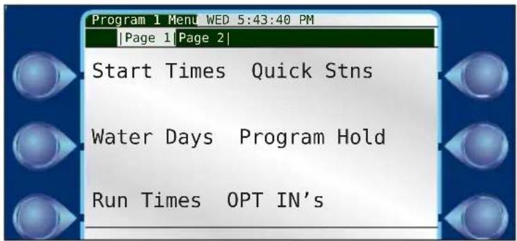

Second screen of Program 1 Setup
Start Times
The DX3 controller is capable of handling 12 start times per program. The Start Time is defined as the precise time of day that a given irrigation or auxiliary program begins.

The procedure to set Start Times was covered in Chapter 3: Quick Start.
Water Days
The DX3 controller offers three modes with which to create an irrigation schedule.
• 14-day: Create an irrigation schedule over a two-week water cycle.
• 31-day: Create an irrigation schedule over a 31-day water cycle.
- Interval: Create an irrigation schedule with a specified number of days between irrigation.

Using the Control Dial, operators can individually assign active irrigation days within the 14-day or 31-day time frame. Operators can also select Alternate or Reverse for quick assignment of irrigation days.
The procedure to set Water Days was covered in Chapter 3: Quick Start.
Run Times
The DX3 controller allows the user to individually set a run time for each station.

The procedure to set Run Times was covered in Chapter 3: Quick Start.
Quick Stations
Quick Stations allow the user to quickly enter a run time for a range of stations instead of individually assigning them as done in chapter 3.
This is handy for stations that share similar vegetation type and sun exposure.

Steps
- to enter the first Station Range field.
- to change the value of the first station. to set.
- to switch to the second Station Range field. to enter.
- to change the value of the second station. to set.
- to switch to the Run Time field. to enter.
- to change the run time value. to set.
- to switch to the Apply Changes field.
- to execute.
Program Hold
A Program Hold can be set, suspending all irrigation activity for that program only for the specified number of days or until manually canceled.

Actively setting a Program Hold for a program will cancel all activity for that program, including non-irrigation activity (see OPT INs next page).


To set a Program Hold for all irrigation programs, do so from the Main Menu screen utilizing the Rain Hold feature.
The procedure to set a Program Hold was covered in Chapter 3: Quick Start.
To Cancel a Program Hold
1) so that the Cancel Program Hold field is highlighted (see above).
2) to cancel.


OPT INs
OPT INs essentially tells the DX3 controller to include a Pump or Master Valve in irrigation operation.

Pumps: Check the physical connections on the main DX3 board to determine what numbers to opt in for installed pump/s (if any).
Master Valves: Check the physical connections on the main DX3 board to determine what numbers to opt in for installed master valves/s (if any).
MV/P Start Delay (sec): This is the amount of time, in seconds, that the Master Valve and Pump will wait after a Program's start time before operating. The reason for this is to make sure irrigation channels are open before water starts being pumped and flowing. A pump can be damaged if it begins pumping with no outlet for the water.
Inter-Station Delay: Yes or No. This is the delay between when one station ends irrigation and the next in the program begins. Setting a delay between stations helps to avoid water hammer.
ISD Delay (sec): This is the length of the Inter-Station Delay in seconds.
MV/P Inter-Station: Off or On. Allows a user to select if a MV/Pump is activated in-between station activations in a program. If an operator has opted to use an Inter-Station Delay of thirty seconds, for example, then he/she might want the pump and master valve to stop working during that delay.
Irrigation Program: Yes or No. Defines if the program is a program that runs irrigation (sprinklers, sprays, rotors, etc.) or a non-irrigation program used to control non-irrigation items (lighting, fountain, etc.).

Rain Hold events will only suspend operation of irrigation programs and not non-irrigation programs. Non-irrigation programs will also not be effected by Flow related alarms such as: Main Line Limit, Unscheduled Flow, Monthly
Water Limit, or station flow alarms.
Omit by Date: Yes or No.
If set to Yes, the specified program will not irrigate on days set under the Omit by Date/s command, under Setup-->Omit by Date.
If set to No, any and all Omit by Date/s will be ignored.
Overlap Protection: Yes or No. Overlap protection prevents programs from running on top of each other. This is handy to prevent too many stations from activating at once and also to prevent two programs activating the same station at the same time.
Continuous Cycle: Yes or No. Continuous Cycle runs an irrigation program over and over again during a user-defined Cycle Start and End time. The Cycle Delay is how long the cycle waits, in minutes, before starting again. It is similar to setting Cycle and Soak for an individual station, but for an entire program.

If Continuous Cycle is turned on for a program, it is necessary to go back to the program's Start Times and define the Cycle Start and Cycle End times.

A twelve hour water window defined during which Program 1 will run over and over.
Over-Water Limit: Warning or Stop. If the monthly irrigation limit is exceeded, this option determines if the DX3 controller generates an alert or stops watering completely.
Moisture Sensing: Yes or No. Moisture sensing enables data logging and collection of moisture data. A moisture sensor (soil sensor) must be wired properly to the controller. Moisture sensor 1-16 have a 1:1 correspondence with programs 1-16. Only one moisture sensor can be used per program.
Establishment Programs
Programs 15E and 16E are designated establishment programs that expire after a user defined duration. Establishment programs are used for growing seed, when frequent watering is needed at first but not after maturity.
Establishment programs are setup the same as a traditional program, except the establishment start and end dates must be defined.

Erase/Reset
To Erase a Program
- to Program Menu Page 2.

- to YES/NO field. to enter.
- to change to YES. to set.
- to Apply Changes field. to
% Adjust
Setting the % Adjust Value field affects irrigation only for that specific program. For example, if you set a % Adjust value of 50% for Program 1, run times that are set to 20 minutes will only run for ten. Program 2 run times will be unaffected.

If you set the \% Adjust value to 150\% for Program 2, run times set for 20 minutes will now run for 30. Program 1 run times will be unaffected.
The procedure to set % Adjust was covered in Chapter 3: Quick Start.
Backup Programs 10 & 11
Programs 10 and 11 are utilized as backup irrigation programs when using Laguna central software Advanced Irrigation Management (AIM) or Advanced ET generated Independent Station Control (ISC) algorithms. If an ISC fails to download from central to the controller for more than 24 hours, the controller will run the backup programs irrigation schedules.
It is strongly recommended to utilize Backup programs when using AIM or Advanced ET generated ISCs in order to maintain any Master Valve or Pump association to a station.

Programs 10 & 11 serve as conventional programs if not using AIM or Advanced ET generated ISCs.
Chapter 6: Stations
The Stations command allows the user to:
- define minimal, nominal, and maximum flow and current amounts for every station in a system
- set parameters for Cycle and Soak to reduce water runoff.
Flow
This screen allows the operator to manually set the minimal, nominal, and maximum flow amounts for every station in a system.

The operator can manually set the minimal, nominal, and maximum settings for each station, or simply check the Learn Flow checkbox at the bottom of the screen. When the Learn Flow/Current command (chapter 5) is activated, the fields for those stations will be filled in automatically.
Current
This screen allows the operator to manually set the minimal, nominal, and maximum current amounts for every station in a system.

The operator can manually set the minimal, nominal, and maximum settings for each station, or simply check the Learn Current checkbox at the bottom of the screen. When the Learn Flow/Current command (chapter 5) is activated, the fields for those stations will be filled in automatically.
Cycle & Soak
Cycle and Soak was developed as a method to ensure the soil absorbs as much of the irrigation water as possible, minimizing water run-off.

Imagine the run time for station 2 is fifteen minutes. However, station 2 irrigates a slope with a walkway at the bottom. If the station irrigates for fifteen minutes straight, most of that water will simply run off the hill and onto the hardscape and be lost. Cycle and Soak is a way to eliminate or drastically reduce that waste.
Cycle Time (Max) - This is how long the station will run in "chunks" towards the overall run time. If station 2 run time is 15 minutes, then, according to the settings above, station 2 will irrigate for 5 minute "chunks" until that run time is met.
Soak Time (Min) - Between those irrigation cycles is the soak time in which no irrigation takes place. Water is allowed to absorb into the soil. After the specified “soak” time, irrigation will resume for another Cycle Time or until the station run time is met.

Soak time may be longer than the minimum time specified.
A DX3 will execute irrigation for other stations in a program during a soak time, instead of waiting idle, in order to optimize a user's water window.
Steps
1) to select the desired station. to set.
2) Turn on Cycle & Soak for that station by
3) to adjust Cycle Time. to set.
4) to adjust Soak Time. to set.
Chapter 7: Reports and Diagnostics
Reports
The DX3 controller can generate two types of reports: controller events and irrigation statistics.

Controller Events
Controller Event reports show controller information such as station start and stop times, station duration, and more. The information displayed will be similar to the information displayed in the Laguna central software, Reports -> Irrigation Statistics reports.

Water Usage
The Water Usage report contains statistics on monthly water usage.
This report can also compare current usage to the previous year..

It is possible to view water usage by individual flow meter, all three, or any combination thereof.

Water usage flow totals are calculated and populated at 12:00 am, each day.
Flow Rates
The Flow Rates screen contains real-time flow rate information for the (up to) three flow sensors attached to the DX3 controller.

Any flow read via a controller's local flow input1, flow input2, or flow input3 will be displayed under local flow.
Any flow read via a downstream/upstream FLOWMAX participating controller's local flow input1, flow input2, or flow input3 will be displayed under remote flow, if the downstream/upstream satellite specifies the flow sources point of connection.
Diagnostics - General

Output Test
The Output Test verifies controller output functionality. Use the Control Dial to set the range of stations to test, adjust the duration (test time per station), and to manually start and, if desired, stop the test.

The DX3 controller will display flow and current information as it cycles through the stations.
Sensor Status

The Sensor Status test displays critical information about each device attached to the system.
Program Test
The Program Test turns on every station within a particular program for the specified Duration (minutes: seconds).


to select a Program to test.
to set the duration for each station of the program in the test.
Start Now to start the Program test.
Previous to test the previous station again.
Next to switch to the next station in the program.

Associated MV's or Pumps will not be activated during Program Test.
Display Test
The Display Test turns on ever pixel on the display to ensure every pixel is functioning.

Keypad Test
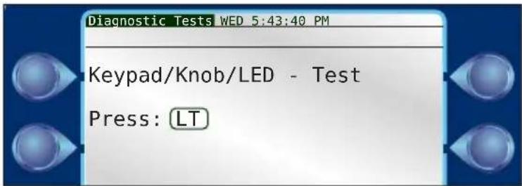
The Keypad Test is to confirm the buttons and Control Dial on the faceplate are functioning properly. The test prompts the user to press each button as directed.
To bypass the test, touch nothing and the test will cancel within five to ten seconds.
Diagnostics - Communications

Second screen of Diagnostics
FLOWMAX Communications
FLOWMAX Communications diagnostics screen displays communication information between the submaster and satellites in the FLOWMAX group.

FLOWMAX Devices
FLOWMAX Devices diagnostics screen displays gallons per minute flow information for any and all attached flow sensors and devices. Additionally, the operator can quickly see how many master valves and/or pumps are active to the system, and if the point of connection is at the submaster or satellite.

FLOWMAX Status
FLOWMAX Status diagnostics screen displays all the possible reasons irrigation activity could be suspended and whether or not that reason does trigger such a suspension.

Communications
ENET
The TCP/IP diagnostic screen displays TCP/IP configuration information, including your controller's IP address, DNS, NetMask, and Gateway.


Ethernet link status is a handy tool to determine whether you have a valid network connection or not.
CELL
The Cellular diagnostic screen displays cellular configuration information.
Select the Refresh Status command to confirm successful cellular communication.

WiFi
The WiFi diagnostic screen displays WiFi configuration information.
Select the Refresh Status command to confirm successful WiFi communication.

M8
The M8 diagnostic screen displays M8 radio configuration information.
Select the Refresh Status command to confirm successful cloud communication.

M7
The M7 diagnostic screen displays M7 radio configuration information.
Select the Refresh Status command to confirm successful cloud communication.

CLOUD
The CLOUD diagnostic screen displays Toro cloud configuration information.
Select the Refresh Status command to confirm successful cloud communication.
![Communication WED 5:43:40 PM |ENET|CELL|WiFi|M8|M7|CLOUD| Selected Cloud Device = Cellular Override/Working IP = [52.38.147.121] Port: 5101 Default Domain/IP: [dx3.cloudconnect.rainmaster.com] [] CLOUD STATUS = Connected (ID 6322) Controller has Authenticated Ping Timeoutm = 50(s) Refresh Status](/content/2026/06/1212635/images/8b9b6fe958a72c54b516eb977af1e5a183577509c1ed5efe8ed87cf3c573a951.jpg)
Chapter 8: Alerts
The DX3 series controller automatically alerts the operator when problems occur or certain conditions arise. The controller may trigger an alert in response to over 11 different conditions. Each condition is date/time stamped and includes additional information which may be helpful in troubleshooting the problem. Up to 15 alerts may be saved in the controller at one time. The user may delete alerts at any time.

Some alerts, such as a main line limit violation, require immediate attention as all irrigation activity is condemned until the alarm is cleared.
Most alerts, due to the controller's programming, do not necessitate immediate operator attention. For example, consider a station with a broken head (FLOW UPPER LIMIT warning). Upon detection of this failure, the DX3 controller will:
- Turn the failed station off.
- Mark the station as condemned (will not water again until the alarm/warning is cleared).
- Advance to the next scheduled station in the program.
- Report the failed station as a warning.
Upon review of the alert, maintenance personnel would repair the problem and then clear the alert at the controller. (Clearing the alert re-enables all irrigation at the station).
Any time an alert is triggered, the DX3 screen displays the alert type.
Anaylzing an Alert
Alerts can be accessed for analysis from the Main Menu.

Alert #: Displays the alert number out of the total number of alerts.
to cycle through the alerts.
Type: There are eleven different types of alerts. See Alert List below.
Recorded: Displays the date and time the alert was triggered.
P/MV: If the alert was related to a pump or master valve, the number of the pump or master valve would be displayed here.
Stn: If the alert was station specific, the number would be displayed here.
Limit: If the alert was limit related (for example, the DX3 controller measured a low flow limit violation), the limit field would display the lower limit value and the measured flow value.
Clearing Alerts
- to scroll through alerts.

to to clear an alert.

To quickly clear all alerts, scroll to the last alert logged and clear, this is the alert type 'Clear to Erase All Alerts'.
Alert List
| Alert Alert Code (displayed with | Laguna central software) |
| RESET | 1101 |
| HIGH TEMPERATURE | 1102 |
| STATION COMMUNICATION ERROR | 1103 |
| MASTER VALVE HIGH CURRENT | 1104 |
| FLOW LOWER LIMIT | 1105 |
| FLOW UPPER LIMIT | 1106 |
| WATER LIMIT | 1107 |
| MAX STATION LIMIT | 1108 |
| START DELAY OVERLAP PROTECTION | 1109 |
| START BLOCK MAX STATIONS | 1110 |
| START BLOCK PROGRAM RUNNING | 1111 |
| SATELLITE OFFLINE | 1112 |
| SATELLITE ONLINE | 1113 |
| HW COMM FAIL | 1114 |
| FM COMM FAIL | 1115 |
| FM STOP WATER | 1116 |
| FM MULTIPLE FLOW METERS | 1117 |
| FM MULTIPLE PUMPS | 1118 |
| FM MULTIPLE MASTER VALVES | 1119 |
| CURRENT_UPPER_LIMIT | 1120 |
| CURRENT_LOWER_LIMIT | 1121 |
| MAIN_FLOW_LIMIT | 1122 |
| UNSCHEDULED_FLOW_LIMIT | 1123 |
| STATION_SHORT_CIRCUIT | 1124 |
| AUTO_LIMITS_ABORTED | 1125 |
| Flow Max Communication Restored | 1126 |
| Flow Max Station Advance | 1127 |
| Power ON | 1128 |
| DAILY_RAIN_LIMIT | 1129 |
| HOURLY_RAIN_LIMIT | 1130 |
| WIND_EXIT_CONDITION | 1131 |
| WIND_ENTER_CONDITION | 1132 |
| UPLOAD_REQUEST | 1133 |
| CLEAR_ALL_ALERTS | 1134 |
| STATION_OPEN_CIRCUIT | 1135 |
| STATION_OVER_CURRENT | 1136 |
| DECODER_PORTS_EXCEEDED | 1137 |
| DECODER_NO_AC_VOLTAGE | 1138 |
| MV CURRENT UPPER LIMIT | 1139 |
| MV CURRENT LOWER LIMIT | 1140 |
| PUMP CURRENT UPPER LIMIT | 1141 |
| PUMP CURRENT LOWER LIMIT | 1142 |
| FLOW MAX LOWER LIMIT (Submaster only) | 1143 |
| FLOW MAX UPPER LIMIT (Submaster only) | 1144 |
These alerts and any corrective action to end the alert condition are explained in full below.
Alerts and Corrective Action

For all alerts, upon resolution of the specific problem, be sure to CLEAR all alerts at the controller.
Reset
This alert is triggered when the DX3 controller detects AC input power.
Clear the alert at the Setup-->Alerts screen.
High Temperature
This alert is triggered when the main board temperature sensor exceeds a threshold value.
Station Communication Error
This alert is triggered when communication fails between the TM and the specific station output board terminal.
Master Valve High Current
The controller expects a certain current delivered to the Master Valve to trigger operation. If the measured current is greater than the expected current, within the preset tolerances, a High Current alert will be triggered.
Flow Lower Limit and Flow Upper Limit
The Flow Lower Limit and Flow Upper Limit alerts are triggered when the measured flow is either less than or greater than the expected flow, + or - preset tolerances. Both alerts display the station number (Stn:) which was on at the time of the limit violation, the Master Valve (MV1) and/or the Pump, the GPM reading (12) as measured by the flow meter, and the limit value set for the station. Upon detection, the controller automatically terminates irrigation on the station and advances to the next station in the program. Condemned stations will not irrigate again until the warning has been cleared.
Flow Lower Limit alert may be caused by:
• A malfunctioning valve
• Incorrectly established individual station limits
• Large variations in static water pressure
- Improper regulation
- Line impediments
Flow Upper Limit alert may be caused by:
• Stuck valve (from previous station)
- Broken pipes/heads
- Unreasonable or inaccurate individual station limits
• Large variations in system water pressure
Flow Alert Troubleshooting
- If station limits are suspected, manually turn each station on and observe the
nominal GPM readings.
- Compare the GPM reading with the limit setting to insure that adequate margin exits (typical: 50% below nominal).
Water Limit
The controller has exceeded its monthly watering allocation (set in the Setup-->Flow-->Flow Options screen). If the program has been set up to stop watering, no further irrigation will occur until day one of the next month. If the program has been set to provide an alert only, and the alert is cleared, then this alert will reappear (though watering continues).
Corrective Action
The Monthly Limit can be increased.
Max Station Limit
This alert is triggered when the controller has attempted, either through manual operation or scheduled operation, to activate more than sixteen stations at one time.
Corrective Action
-
Try to locate the "overstacked" schedule program.
-
If the alert was triggered by an overstacked manual operation, for example setting too many simultaenous stations to execute at once, there is nothing to be done other than not to exceed the simultaneous station limit again.
Start Delay Overlap Protection
This alert is triggered when the DX3 attempts to start a second program when the first program is still active and Overlap Protection (under Program-->OPT INs) is active for that first program.
Start Block Max Stations
This alert is triggered when the DX3 controller attempts to operate more than the number of maximum stations at one time.
Start Block Program Running
This alert is triggered when the operator has programmed the DX3 controller to start a program that is already running. For example, Program 1 starts at 6am every morning and runs for three hours. At 8am, the operator attempts to manually run Program 1 from the Manual menu. An alert is generated.
Satellite Offline / Online
This alert is triggered when the satellite loses / reestablishes contact with the submaster.
Hardware (HW) Communication Failure
Set on submaster to indicate it lost communication with a satellite not configured for Flow Max.
FlowMax (FM) Communication Failure
Set on submaster to indicate it lost communication with a satellite configured for Flow Max.
FlowMax Stop Water
This alert is triggered when the controller is in a stop watering state.
FlowMax Multiple Flow Meters
This alert is triggered when the specified flow meter is defined on more than one controller in the Flow Max group. DX3 will add flows together for multiply defined flow meters.
FlowMax Multiple Pumps
This alert is triggered when more than one controller in the flow max group has the specified pump defined. DX3 will operate all multiply defined pumps in tandem.
FlowMax Multiple Master Valves
This alert is triggered when more than one controller in the flow max group has the specified master defined. DX3 will operate all multiply defined masters in tandem.
Current Upper / Lower Limit
This alert is triggered when actual current was above maximum current or below the minimum current allowed.
Main Flow Limit
This alert is triggered when flow exceeded main line flow limit.
Unscheduled Flow Limit
This alert is triggered when flow exceeded unscheduled flow limit.
Station Short Circuit
This alert is triggered when decoder reports short circuit.
Auto Limits Aborted
This alert is triggered when auto limits process was terminated before completion.
FlowMax Communication Restored
Flow Max configured satellite triggers this alert when it has established or restored communication with the Submaster.
FlowMax Station Advance
This alert is triggered when the satellite is a FLOWMAX participant and received station advance from a FLOWMAX related alarm.
Power ON
This alert is triggered when the controller resets and restarts after a power disruption.
Daily / Hourly Rain Limit
This alert is triggered when rain exceeded daily / hourly rain limit.
Wind Exit / Enter Contition
This alert is triggered when wind was below / above limit for prescribed time, wind shutdown is ended / started.
Upload Request
User has indicated they wish controller settings to be uploaded by the central.
Clear All Alerts
Clearing this alert will clear all alerts, and all underlying flags that may have been orphaned if alerts were overwritten.
Station Open Circuit
This alert is triggered when decoder reports open circuit.
Station Over Current
This alert is triggered when decoder reports over current.
Decoder Ports Exceeded
This alert is triggered when decoder reports too many ports on.
Decoder No AC Voltage
This alert is triggered when decoder reports no AC voltage.
MV Current Upper Limit
Indicates Master Valve current draw exceeded the maximum allowed. Alert will display the measured current and maximum limit.
MV Current Lower Limit
Indicates Master Valve current draw was below the minimum allowed. Alert will display the measured current and minimum limit.
Pump Current Upper Limit
Indicates Pump current draw exceeded the maximum allowed. Alert will display the measured current and maximum limit.
Pump Current Lower Limit
Indicates Pump current draw was below the minimum allowed. Alert will display the measured current and minimum limit.
FLOW MAX Lower Limit (Submaster Only)
Indicates actual flow was below minimum flow allowed. Alert will display measured flow and lower limit.
FLOW MAX Upper Limit (Submaster Only)
Indicates actual flow was above maximum flow allowed. Alert will display measured flow and upper limit.
Chapter 9: Rain Hold
There are several ways in which a DX3 can be placed in Rain Hold. This chapter will focus on a globally set Rain Hold. For a local program level Rain Hold, please refer to Chapter 6, Program Hold. A global Rain Hold can be set manually via Main Menu -> Rain Hold. When activated, Irrigation Rain Hold will suspend irrigation activity for the specified number of days (or until canceled).
Additionally, a Rain Hold can be set via a tipping bucket rain sensor, rain switch sensor, freeze switch sensor and/or Laguna central software. A sensor related Rain Hold event will be displayed at the bottom of the screen. For connecting sensors to a DX3 controller, see Appendix B.


Non-irrigation programs (such as lighting or for a fountain), are NOT placed on a Rain Hold with this command).
To Place a Rain Hold for a specified number of days:
1) Enter Set Day(s) field.
2) Change to desired number of days.
3) Set value.
4) When done, press T R.
To Place a Rain Hold for an indefinite period of time:
1) to Set Until Canceled field.
2) to activate indefinite rain hold.
To Cancel a Rain Hold
1) to the Cancel Hold field.
2) to cancel.

Canceling a Rain Hold here does not cancel a Rain Hold set for an individual program.

Rain Hold by Program is found under Chapter 5: Program Entry.
Chapter 10: Manual Operation
Operators can manually activate irrigation for a single station, a group of stations, or a program. There are four manual options:
- Station: Activate a single, specific station for a specified amount of time.
- Simultaneous: Allows an operator to activate multiple stations as they are activated. The DX3 can operate sixteen stations simultaneously.
- Sequence: Stations can be activated in a non-linear sequence.
- Program: Execute the specified program at the specified time.

Station
It is possible to manually activate any station within the DX3 system.
Master Valves and/or Pumps can be activated independently of stations by selecting station '000' then enabling the desired Master Valves and/or Pumps to active.
The DX3 monitors current and--if a flow meter is installed--flow.

To Activate Manual Station Operation:
1) to enter Station# field.
2) to select desired station. Set it.
3) and to enter, adjust, and set Run Time.
4) Navigate to the Activate field. to begin the manual station. Irrigation will begin immediately.

As stations are activated, the master valve (MV) and/or pump (P) associated with that station will be highlighted, indicating they will activate along with that station. It is possible to manually enable and disable the master valve/s and pump/s, although Rain Master does NOT recommend that.
To Deactivate Manual Station Operation:
1) to Deactivate field.
2) to deactivate.


Learn Now
The Learn Now command can be executed to manually learn flow and current settings for the specified station. Learn Flow and Learn Current must be turned on under Setup --> Stations --> Flow and Current screens.
To use the Learn Now function for current measurements, only one station can be activated (as in, no multiple stations, master valves or pumps).
Simultaneous
The DX3 controller can operate up to sixteen stations simultaneously. As you activate stations, the DX3 monitors flow and current.

To Activate Simultaneous Operation:
1) to enter Station# field.
2) to select desired station. Set it.
3) and to enter, adjust, and set Run Time.
4) Navigate to the Activate field. to begin the manual station. Irrigation will begin immediately.
5) User must activate each station, then has the option to activate another. Repeat steps 1-4 to activate up to fifteen more stations.

As stations are activated, the master valve (MV) and/or pump (P) associated with that station will be highlighted, indicating they will activate along with that station. It is possible to manually enable and disable the master valve/s and pump/s, although Rain Master does NOT recommend that.
To Deactivate Simultaneous Station Operation:
1) to Deactivate field.
2) to deactivate.
Sequence
Sequence allows stations to be activated in a non-linear sequence.

To Activate a Sequence Operation:
1) to enter Station# field.
2) to select desired station. Set it.
3) to Run Time field. 4) to set a run time. Set it.
5) to Add field. to add station to the sequence.
6) Repeat steps 1 - 5 to add as many stations as desired to the sequence.
4) To begin the manual program, to Start field. to start. Irrigation will begin immediately.
To Cancel a Manual Sequence Operation:
Once a Sequence operation has started, the Start field will read Stop.
1) to the Stop field and .
- or -
1) Hit the All Stop button (which stops all irrigation, not just the Sequence).
Program
Manually executing a program will run the program at the specified start time.

To Activate a Manual Program Operation:
1) to enter Program# field.
2) to select desired program. Set it.
3) Use the Control Dial to enter, adjust, and set the remaining fields.
4) to begin the manual program. Irrigation will occur at the specified start time.
To Deactivate a Manual Program Operation:
1) to Deactivate field.
2) to deactivate.
Chapter 11: Review
Overview
The review screen allows the user to review all facets of the controller setup and programming, including System Review, Program Review, About, Station Review, Flow Review, and Weather Review.

System Review
The System Review section allows a user to review all valid programs, including establishment programs, standard programs, and ISC programs.

The second of 4 screens displays the satellite type and firmware revision.

The remaining pages display the omit days for the controller.

Program Review
Program Review displays five screens of information related to the selected irrigation program.
1/5:

- Program Valid: Yes or No. For a program to be valid, it must have four settings: a Start Time, a Run Time, water days, and assigned stations.
- Start Duration: Displays how long the entire irrigation program will run in hours and minutes.
- Water Use per Start (gal): Displays the number of gallons the irrigation program uses. Water usage is calculated based off the nominal station flow value. See Chapter 7, Stations for entering nominal flow values or performing a Learn Flow
- Start Times: Shows the start and end times for each program start.

When toggling between program numbers, it is common for the controller to have a 1-2 second delay before populating the data.
2/5:

- Schedule Type: Displays what type of schedule is set for this program, either 31-Day, 14-Day, or Interval.
- Establishment Active: Pertains to programs 15E & 16E, which utilize an establishment or grow in period for new seed. See chapter 6, Program Entry for details on establishment programs 15E and 16E
• Water Days (in next two weeks): Displays the dates of the irrigation days over the next two weeks.
- Backup Active: Pertains to programs 10 and 11, which are utilized as a backup irrigation programs when using Laguna central software Advanced Irrigation Management (AIM) or Advanced ET generated Independent Station Control (ISC) algorithms. If an ISC fails to download from central to the controller for more than 24 hours, the backup program will run its irrigation program.
- Hold Program Active: Pertains to how many local program level Rain Hold days remain for that program. Global Rain Hold events are not relevant here.
3/5:

This screen displays the OPT IN's set for the specified program.
• Master Valves: All master valves associated with that program.
- Pumps: All pumps associated with that program.
- MV/P Start Delay(s): The number in seconds of the MV/P Start Delay.
• Inter-Station Delay(s): Whether or not there is an inter-station delay.
• MV/P Inter-Station: If a MV/Pump is activated in-between station activations.
- Irrigation Program: Disapplays whether the program is an irrigation program or a non-irrigation program.
• Continuous Cycle: Displays whether the program will continuously cycle.
4/5:

• Percent Adjust: Displays the Percent Adjust set in Chapter 5: Program Entry.
- Station Run Times: Displays how long each station will run, taking into account the Percent Adjust setting.
- Turn the Control Dial to see more station run times.
5/5:

• Station Sequence: START DELTA: EVENT
Station Review
Station Review shows irrigation information for each station attached to the controller.

- Station Type: "L" - local conventional station "D" - 2-wire decoder station
- Last Confirmed On: The last date and time that station was active.
- Ran Today: The number of minutes the station was active.
- Soak Remain: Displays the Soak time left (if any) from the Cycle and Soak setting.
Flow Review
Flow Review displays information about the various flow meters (if any) that are added to the system, as well as the system Flow Limits.

All of this information is set under Setup --> Flow.
About
Displays the controller name, version, checksum, build, bootloader type/version, the controller serial number (set at factory), Opt. FW and Cloud ID (set at factory).
The Opt. FW displays the firmware version of the Master Valve/Sensor board, followed by each output board in order.

Weather Review
Review
This screen shows recent weather information for the previous week such as rainfall in inches, ET in inches, and current wind speed. Appropriate sensors and/or data sources must be attached to generate this data.
![Weather Review WED 5:43:40 PM [Review|Rain Limits|Wind Limits] Rain Today (TUE) 0.00 inches Previous Days: SUN MON WED THU FRI SAT 0.00 0.00 0.00 0.00 0.00 0.00 ET Today (TUE) 0.00 inches Previous Days: SUN MON WED THU FRI SAT 0.00 0.00 0.00 0.00 0.00 0.00 Wind Now 0.0 mph](/content/2026/06/1212635/images/668a457c2c1680db46300b26319e762a1f6c4d40cb16194d1e10a971a36a9436.jpg)
Rain Limits
Rain Limits screen displays both the hourly and daily threshold limits and totals. If rain limits are met or exceeded, the controller will suspend irrigation activity and issue an alert. Irrigation will resume based off the user settings defined in Rain Hold menu.


Thresholds can only be set via Laguna central software.
Wind Limits
Wind Limits screen displays the wind shutdown and resume settings. If wind is measured at or above the Wind Shutdown speed for the Duration Required, the controller will suspend irrigation activity and issue an alert. The controller will resume irrigation when the wind is measured at or below the Canceled Speed for the Duration Required.


Thresholds can only be set via Laguna central software.
Shutdown speed: The minimum wind speed (for the duration specified) to trigger an irrigation shutdown.
Cancel speed: The maximum wind speed that cannot be exceeded for the duration specified that cancels, automatically, a wind speed shutdown.
Duration Required: Time interval required for a shutdown or resume limit to be valid.
Chapter 12: Troubleshooting
This chapter describes the resources available to troubleshoot field wiring problems, broken heads, pipes and mainlines, AC power problems, monitoring of water usage, and more.
In order to take full advantage of all the capabilities of the DX3 controller as a maintenance tool, refer to the following manual sections for operational information and proper setup:
- Flow Monitoring: See Appendix B: Flow Meters
- Broken field wiring, short circuits, and faulty valve solenoids: See Appendix C: Current Monitor
Communications Wiring Issues (Satellite to Satellite)
All alerts are systematically retrieved and recorded by the Central Control Computer. Central software has reporting tools to comprehensively sort, organizer and filter alerts by various parameters.
DX3 satellite groups use a daisy chain configuration, that will result in failed communication to all downstream devices at the point of failure. Here is an example:
A FLOWMAX group is hardwired together consisting of four satellites
Submaster_001-00 <-> Satellite_001-01 <-> Satellite_001-02 <-> Satellite_001_03
If the communication line is severed between satellite 001-01 and 001-02, all satellites downstream of 001-01 lose communication with the submaster. In this case, that would be Satellite_001-02 and Satellite_001-03. This would result in alerts at the submaster for loss of communication with the given satellites and an alert at satellites 001-02 and 001-03 for loss of communication with the submaster.
Submaster
If the submaster loses communications with one of its hardwired satellites, a hardwire (HW) communications failure is detected (below). An entry is made in the submaster's alert list.

Satellite
When a satellite loses hardwire communication, it is "off-line". When communication is re-established, it is "on-line" (see Alert below). When a satellite becomes off-line or on-line, an entry is logged in the satellite's alert list.

Communication Wiring Issues (Satellite to Station):
For both conventional and 2-wire decoder stations, if a satellite cannot communicate with a given station, a specific alert will be generated.

For conventional stations, verify the cable connection to the output board responsible for that station. Verify the output board has the proper power and status LEDs illuminated. Under the "Review -> About" menu, verify the Opt. FW for the given output board is displayed. If the cable connection is good but the power/status LEDs are not illuminated correctly, or the Opt. FW cannot be read, contact a Rain Master service representative.
For 2-wire decoder stations, verify the cable connection to the 2-wire output board. Verify the 2-wire output board has the proper power and status LEDs illuminated. Verify the field wiring connection to the 2-wire output board. In the field, check the field wiring and connections to the given station.
Diagnostics
The DX3 controller utilizes several advanced tools for communication troubleshooting. These tools are used by RMIS service personnel to diagnose and correct field communication problems. These tools are detailed in Chapter 7: Reports and Diagnostics.
Directory of Flow Chart Diagnostic Problems
Problem / Symptom Page
Multiple Stations Do Not Water
(Many station lights on)
Short Circuit Shutdown 86
Automatic Program Does Not Start 87
Flow Sensor Reading Always Zero 89
A Station/Valve Does Not Water 92
Display is Blank 95
Program Starts-But Does Not Water 96
Program Starts-But Stations Shut Off Immediately 97
Monthly Flow Violation Occurred But Program Still Operates 98
Multiple Stations Do Not Water
(Many station lights on)
Station LED for the suspect zone turns on, and other station LEDs turn on.
If a zone does not water but that station's red LED light turns on as well as other various LEDs for other stations, the field "common" wire for those stations is not connected (floating) to the controller. Check the field wiring common connection at the controller and at the field junction where they may be tied together. Check for continuity of the common line from the controller to the field valve.
The following schematic diagram illustrates a sample wiring configuration of four solenoids connected to station outputs:
Controller Station Output Board

The solenoids connected to station outputs 1, 4, and 7 share one common line return to the station output board. Station #9 is shown as a normal operating station, which is connected independently from the other stations (not sharing the common connection).
If the common line is broken or open (as shown by the cross marks), current does not flow and the solenoid is not energized. This condition is possible whenever groups of field valve wiring configurations are tied together to one common return line.
In the example above, if station 1, 4 or 7 are activated, the station LEDs for 1, 4 and 7 will all illuminate but the solenoids will not energize.
Note: Station 9 LED will not be illuminated and solenoid will not be energized because station 9 does not share a common with station 1, 4 or 7.
Short Circuit Shutdown
A short circuit shutdown event is generated when the total cumulative current draw of all conventional outputs (stations, MV's and Pumps) measured by the MV/Sensor board exceeds 2.75Amps. An alarm will be generated and the MV/Sensor board will sever the common connection to all conventional outputs, preventing them from energizing. The severed common connection can be quickly diagnosed by the illumination of the shutdown LED (reads 'OFF' on main board cover).

Once the alarm is cleared, the MV/Sensor board will reset the common connection.
Note: In the event of a short circuit shutdown, no station LEDs will illuminate if activated. If a MV or Pump is activated, all MV and Pump LEDs will illuminate in the same manner as station outputs sharing a common connection will, as described in the previous section.
Automatic Program Does Not Start

flowchart
graph TD
    A["Start"] --> B{Are alerts displayed?}
    B -->|Yes| C["See Alerts list"]
    B -->|No| D{Check Program Review. Is program valid?}
    D -->|No| E["Review valid program requirements"]
    D -->|Yes| F{RAIN OFF LED is on?}
    F -->|No| G["next page"]
    F -->|Yes| H{Has a rain, freeze, tipping bucket, wind, or auxiliary sensor been setup?}
    H -->|No| I["Adjust / cancel Global- or Program-level Rain Hold"]
    H -->|Yes| J["Refer to sensor documentation"]
Automatic Program Does Not Start (continued)

flowchart
graph TD
    A["from previous page"] --> B{Is "Omit by Date" currently active?}
    B -->|Yes| C["Adjust Omit by Date dates"]
    B -->|No| D["% Adjust set to zero?"]
    C --> E["Contact Rain Master Technical Support"]
    D -->|Yes| F["Adjust % Adjust"]
    D -->|No| G["End"]
Flow Sensor Reading Always Zero

flowchart
graph TD
    A["Start"] --> B{Are flow sensor K and Offset values set correctly?}
    B -->|No| C["See Appendix B: Flow Meters for proper settings"]
    B -->|Yes| D{Is installation of flow sensor correct?}
    D -->|No| E["Check: a) direction of flow sensor\nb) continuity of sensor cable\nc) sensor calibration"]
    D -->|Yes| F{Is water physically passing through the flow sensor?}
    F -->|No| G["Does a: manual valve need to be opened?\npump need to be turned on?\nmaster valve need to be turned on?"]
    F -->|Yes| H["Disconnect sensor wires from "Input 1+" and "Input 1-" terminals."]
    H --> I{Using an ohm meter, is there 12+ VDC measured at inputs 1+ and 1-terminals?}
    I -->|No| J["Contact Rain Master Technical Support"]
    I -->|Yes| K["next page"]
Flow Sensor Reading Always Zero (continued)

flowchart
graph TD
    A["from previous page"] --> B["Navigate to Reports & Diagnostics --> Diagnostics --> Sensor Status then short the 1+ and 1- terminals together repeatedly."]
    B --> C{Does the associated MV1 green LED turn on and off when shorted and when not?}
    C -->|No| D["Contact Rain Master Technical Support"]
    C -->|Yes| E{Does the sensor diagnostic page update the associated Flow channel HZ reading when shorting the terminal receptively?}
    E -->|No| D
    E -->|Yes| F["Reconnect sensor wires to input 1+ and 1- terminals."]
    F --> G["next page"]
Flow Sensor Reading Always Zero (continued)

flowchart
graph TD
    A["from previous page"] --> B["Disconnect the EV-CAB-SEN wires from the flow sensor red and black wires."]
    B --> C{Is there 12+ VDC measured at black and white EV-CAB-SEN wires?}
    C -->|No| D["EV-CAB-SEN is defective. See Appendix G for measuring continuity."]
    C -->|Yes| E["Insure all water is off. Drain line to relieve pressure."]
    E --> F["Remove sensor insert."]
    F --> G{Is debris impeding sensor movement?}
    G -->|Yes| H["Remove debris."]
    G -->|No| I["Replace defective sensor."]
    H --> J["Reinsert sensor. Connect wires. Retest."]
Station / Valve Does Not Water

flowchart
graph TD
    A["Start"] --> B{Are alerts displayed?}
    B -->|Yes| C["Refer to Alerts list. Take corrective action. Clear alert."]
    B -->|No| D["Using Manual operation, turn on suspect station for five minutes."]
    D --> E{Are alerts displayed?}
    E -->|Yes| F["Refer to Alerts list. Take corrective action. Clear alert."]
    E -->|No| G{On output board, does active station's light turn on?}
    G -->|No| H["Power down controller. Check cable connections between main board and output board and fuses."]
    G -->|Yes| I{Is station field wiring properly connected at output?}
    I -->|No| J["Refer to Station Connection diagram. Verify wiring and connections."]
    I -->|Yes| K["next page"]
Station / Valve Does Not Water (continued)

flowchart
graph TD
    A["from previous page"] --> B{Is the electrical current within the expected range?}
    B -->|No| C["Isolate problem."]
    B -->|Yes| D{Does a master valve or pump need to be turned on for the station to operate?}
    D -->|No| E["Refer to master valve and pump setup."]
    D -->|Yes| F{Is the MV and/or pump light on?}
    F -->|No| E
    F -->|Yes| G["Isolate problem to field wiring / valve solenoid or controller as follows: <br>At the station output board, swap the station wires of the defective station with a known working station."]
    G --> H["next page"]
Station / Valve Does Not Water (continued)

flowchart
graph TD
    A["from previous page"] --> B["Manually operate the known working station output that is wired with the suspect defective station wires for one minute."]
    B --> C{Does irrigation commence for the known working station?}
    C -->|No| D["If station alerts are raised, react as necessary.<br>Verify integrity of field wiring from output board to solenoid and repair / replace if faulty.<br>If field wiring is OK, replace valve / solenoid for the defective zone."]
    C -->|Yes| E["Field wiring and solenoid good. Now test electrical output."]
    E --> F["Manually operate the suspect station output that is wired to the known good station for one minute."]
    F --> G{Does irrigation commence for the suspect working station?}
    G -->|No| H["If station alerts are raised, react as necessary.<br>If you suspect faulty electrical output, contact Rain Master technical support."]
    G -->|Yes| I["Electrical output good."]
Display is blank

flowchart
graph TD
    A["Start"] --> B["Verify AC power switch inside controller is in the "On" position."]
    B --> C["Verify GFI circuit breaker is reset. Press "red" button to reset."]
    C --> D["Verify main circuit breaker at remote power source is on."]
    D --> E{At MV board, are all 5 power LEDs illuminated?}
    E -->|No| F{Is the fuse blown?}
    F -->|Yes| G["Replace fuse and retest."]
    F -->|No| H["Consult Rain Master technical support."]
Program Starts But Does Not Water

flowchart
graph TD
    A["Start"] --> B{Are alerts displayed?}
    B -->|Yes| C["Refer to Alerts list. Take corrective action. Clear alert."]
    B -->|No| D{Does the program require a master valve or pump?}
    D -->|No| E["Refer to a "Station/Valve Does Not Water"."]
    D -->|Yes| F{When the program starts, do LEDs for the MV or pump turn on?}
    F -->|Yes| G["Check master valve and pump have been properly connected to the DX3 main board terminals."]
    F -->|No| H["Assign proper master valve and pump to program."]
Program Starts But Stations Shut Off Immediately

flowchart
graph TD
    A["Start"] --> B{Have maximum flow limits been exceeded?}
    B -->|Yes| C["See Flow Limits. Verify flow limits for each station."]
    B -->|No| D{Have minimum flow limits been set?}
    D -->|Yes| E{Have maximum current limits been exceeded?}
    D -->|No| F["Consult Rain Master technical support."]
    E -->|Yes| G["See Current Limits. Verify current limits for each station."]
    E -->|No| H{Have minimum currents been met?}
    H -->|Yes| I["Refer to Alerts list. Take corrective action. Clear alert."]
    H -->|No| J{Are alerts displayed?}
    J -->|Yes| K["Consult Rain Master technical support."]
    J -->|No| L["End"]
Monthly Flow Violation Occurred But Program Still Operates

flowchart
graph TD
    A["Start"] --> B{Has the program been setup as an irrigation program?}
    B -->|No| C["See program options to change. (Recall that non-irrigation programs are unaffected by flow violations.)"]
    B -->|Yes| D{Has the program been set up to stop watering at water limit?}
    D -->|No| E["See Water Limit. Change setup option from "Warning" to "Stop" (watering)."]
    D -->|Yes| F["Consult Rain Master technical support."]
Control Devices
(Rain Sensors, Freeze sensors, Etc.)
Many commercial sensor devices available in today's market take advantage of the common ground configuration to control watering operations. Devices such as rain sensors, freeze sensors, moisture sensors, etc. employ a control system which interrupts the common ground line of watering stations to control the shutdown of stations.
These devices have inherent limitations:
- They exhibit "contact bounce" or jitter when the on/off threshold is reached. This may have adverse affects on pump systems.
- Since they interrupt common lines, non-irrigation programs such as lighting programs are also affected.
- It may be difficult to identify/interrupt the "common" wire if multiple commons come in from the field.
Appendix A: Specifications
Cabinet Dimensions:
- Wall Mount: 11" W x 16" H x 5.625" D (27,9cm W x 40,6cm H x 14,29cm D)
- Pedestal Mount:
PSB: 16.5" W x 38" H x 17.25" D (41,9cm W x 96,5cm H x 43,8cm D)
SPED: 16" W x 34" H x 16" D (40,6cm W x 86,4cm H x 40,6cm D)
Temperature Range:
- Operating: +14^ to +140^ (-10°C to +60°C)
- Storage: -22^ to +149^ (-30°C to +65°C).
Power Specifications:
- Internal Transformer, Class 2, UL Listed, CSA Certified (or equivalent)
Input: 120 VAC, 60 Hz, 1A
Output: 24 VAC, 50/60 Hz, 100 VA max
- Junction Box Power Outlet: 120 VAC, 5 AMP max
• Maximum Load Per Station: 2.5A @ 24 VAC @ 77° (25°C)
• Maximum Load Per Master Valve: 2.5A @ 24 VAC @ 77°F (25°C)
• Maximum Load Per Pump Output: 2.5A @ 24 VAC @ 77°F (25°C) - Total cumulative output load (station, MV, and pump): 2.75A
• Total Maximum Load: 4A @ 24 VAC.
Output Surge Protection (excluding 2-wire decoder models):
20KV common, 18KV normal.
Controller Memory:
The DX3 utilizes NVRAM (Non-volatile Random Access Memory) technology to protect all user-defined program and setup data from loss in the event of a power failure. Time and date settings will be maintained without power for approximately 30 days.
Appendix B: Flow Sensors
The DX3 controller provides a variety of user-configurable, flow-related features for up to three flow sensors, referred to as Flow #1, Flow #2, and Flow #3. Flow sensors may be of both conventional and/or decoder type.
DX3 flow features/capabilities include:
- Display of instantaneous flow rate in gallons per minute (GPM) for all three meters as well as total (Flow #1 + Flow #2 + Flow #3). Flow rates are updated every ten seconds.
-
Display of monthly flow accumulations in gallons for all three flow meters as well as total (Flow #1 + Flow #2 + Flow #3). Flow accumulation in gallons is updated every minute.
• Automatic termination of watering based upon flow limit violations: -
Main line flow rate for controller (GPM)
• Maximum flow rate per station (GPM)
• Minimum flow rate per station (GPM)
• Maximum flow accumulation per month (gallons)
• Unscheduled flow rate for controller (GPM)
- Automatic condemnation and reporting of stations violating flow limits. Alert information is provided in Chapter 8: Alerts.
• Automatic establishment of station upper and lower flow limits (Learn mode).
Flow Sensor Installation Instructions
The plastic cover of the DX3 main board shows all inputs and terminal polarity. To install a Irritrol or Rain Master flow meter:
- Power down the DX3 controller.
- Connect the white and black wires as shown.

- Return power to the controller.
- To configure the flow sensor, go to Setup-->Flow-->Flow Sensors. See Chapter 4: Setup on how to navigate the Flow Sensors screen. Use the "Flow Meter Offset and K Values" tables (next page) to properly calibrate the flow sensor.
Flow Sensor Overview
To establish flow limit checking either on a controller or individual station basis, verify the following:
- Flow meter is installed properly.
- Correct Offset and K values are entered.
- Station Upper Limits have been established. See "Max Flow Limit".
- Station Lower Limits have been established. See "Min Flow Limit".
- Main line flow limits have been established. See "Main Flow".
• Total Monthly Flow has been set. See "Flow Options".
- Unscheduled Flow Limit has been defined. See "Unscheduled Flow Limit".
- Upper and lower limit checking is enabled. See "Enable/Disable Limit Checking".
- The appropriate flow limit check delay has been established. See "Delay Limit".
- Selection of at least one of the three flow meters. See "Setup -> FLOWMAX, devices connected to this clock."
If all above steps are completed, typical accuracy values of flow sensor readings are approximately within 1%.
Flow Sensor Offset and K Values
Each flow meter installation must include entry of the "offset" value and "K" values for proper calibration of the meter. The DX3 controller supports the complete line of Rain Master and Irritrol-branded flow sensor (DI & CST). Flow Sensors may be either conventional and/or decoder type. The controller can only have 3 in total.
Data Industrial® Flow Sensors
PVC Sensor Body Material
| Sensor Model # FS-150 FS-200 FS-300 FS-400 | ||||
| Pipe Size 1.5” 2” 3” 4” | ||||
| Operating Range (GPM) 5-100 5-100 5-100 5-100 | ||||
| Max. Water Pressure 100 psi | 100 psi 100 psi | 100 psi | ||
| K-Value 457 776 2268 3752 | ||||
| Offset Value 0 104 483 834 | ||||
| Connection Type | Slip Slip | Slip Slip | ||
Bronze Sensor Body Material
| Sensor Model # | FS-B100 | FS-B125 | FS-B150 | FS-B200 | FS-B250 |
| Pipe Size | 1” | 1.25” | 1.5” | 2” | 2.5” |
| Operating Range (GPM) | 2-40 | 3-60 | 4-80 | 10-100 | 16-160 |
| Max. Water Pressure | 400 psi | 400 psi | 400 psi | 200 psi | 200 psi |
| K-Value | 109 | 209 | 291 | 750 | 1021 |
| Offset Value | 27 | 32 | 24 | 0 | 370 |
| Connection Type | NPT Female | NPT Female | NPT Female | NPT Female* | NPT Female |
* Includes copper male adapter.

In addition to the standard models listed above, an impeller-type flow sensor adapter, Model #FS-INSERT-B, is available to accommodate pipe sizes from 3" to 40" (7.6 to 102 cm). Requires pipe saddle with 2" female NPT inlet.
CST Flow Sensors
| Sensor Model # | FS-10 | FS-B15 | FS-15 | FS-20 | FS-30 | FS-40 | FS-60 |
| Pipe Size | 1" | 1.5" | 1.5" | 2" | 3" | 4" | 6" |
| Operating Range (GPM) | .86-52 | 3-90 | 1.8-108 | 2.8-170 | 6-288 | 10-480 | 45-1080 |
| Max. Water Pressure (psi) | 240 | 250 | 240 | 240 | 150 | 150 | 150 |
| K-Value | 87 | 208 | 177 | 325 | 751 | 1237 | 2839 |
| Offset Value | 6 | 34 | 205 | 256 | 431 | 303 | 903 |
| Connection Type | Socket | FIPT | Socket | Socket | Saddle | Saddle | Saddle |
Flow Limit Checking
To perform limit checking, the controller computes a Gallon-Per-Minute (GPM) flow rate based upon the total gallons used in the previous 60 seconds.
Limit checks are performed on the following:
- Station upper limit
- Station lower limit
- Main flow limit
• Total monthly flow limit - Unscheduled flow limit
Station limits can be automatically established by the controller or manually entered.
Station Limit
It is possible to enter a station flow limit by manuall entering the station limit, as described in Chapter 7 or 11, or have the controller automatically set the limit during a "learn" process as described in Chapter 5. Ensure the flow check delay is set to a high enough value to allow for adequate hydraulic settling time for the flow meter readings to stabilize before obtaining the nominal flow rate.
The controller compares the flowmeter reading to the station limit. If the meter value is larger than the station upper limit, a high flow alert is raised. If the meter value is smaller than the station lower limit, a low flow alert is raised.
The suggested upper limit flow rate should be set to the nominal flow rate for the station +20%. The suggested lower limit flow rate should be set to the nominal flow rate for the station -20%.

If water pressure varies greatly, upper station limits should be increased.
Main Flow Limits
Enter the Main Flow Limit, as described in the Main Flow procedure in Chapter 5. The controller compares the flow meter reading to controller/main line station limit. If the meter value is greater than the limit, an alert is generated.
The system default value for controller/main line limits is 500 GPM.
The Main Flow upper limit should be set higher than the total of all simultaneously "on" stations. However, this limit should be lower than the anticipated flow rate from a main line break.
In Flow Max systems, the total water consumption of all participating controllers is calculated into the Main Flow limit.
Total Monthly Flow Limit
Enter a maximum monthly flow limit, as described in Chapter 4. The controller compares the accumulated monthly flow to maximum monthly flow limit. If the accumulated flow is greater than the limit, an alert is generated.
The system default value for maximum monthly total is 9,999,999.
If the monthly limit is exceeded, there are two options available, STOP and WARNING. See Chapter 5: Program Entry for details on selecting each option.
If the STOP option is selected, the problem is reported in the alert list and watering stops.
Watering is restarted when:
• the limit is changed to a larger value
• the program option is changed to Warning
- a new month begins
If the WARNING option is selected, an alert is reported in the alert list and watering continues.
Unscheduled Flow Limit
Unscheduled Flow Limit is defined as any water flow that is not programmed or under the control of the controller. If a water flow is greater than the limit, the flow check delay has been met, and no stations are on, the controller will shut down the water supply until the condition is corrected.
Unscheduled Flow conditions may be due to broken water lines, defective valves, faulty solenoids, etc.
The Unscheduled Flow procedure is given in the Controller Setup section of Chapter 4. The default limit is 0 GPM.
Enabling and Disabling Flow Limit Checking
Once the station limits have been established, the flow limit checking (upper and lower limits) may be enabled or disabled. When upper limits have been enabled, all station upper limits will be enforced. When lower limits have been enabled, all station lower limits will be enforced. See Chapter 4 for the steps to enable or disable station flow limit checking.
When limits are disabled, no limit checking is performed. However, the GPM flow, total monthly flow readings, the Monthly Limit, Main Line Limit, and unscheduled limits are all unaffected.
Delaying Flow Rate Limit Checking (Flow Check Delay)
Due to drainage of water lines, the initial flow rate for a station may be much higher than the station steady state condition. To prevent erroneous station fault detections, the controller delays a period of time after a station is turned on before making flow rate limit checks. This delay may be set from 2 to 6 minutes.
The system default for delay of limit checking is two (2) minutes.
To establish the proper delay, monitor the GPM flow rate for each station in the irrigation program(s).
Observe which station takes the longest time for its GPM rate to "settle." Round this time period to the next minute and use this rounded value as the flow rate limit check delay.
Limit Checking with Two or More Flow Meters
When two flow meters are used, you may select which meter is used for limit checking. Alternately, you may check the total flow from both meters. Do this by:
- Under Setup --> Flow --> Flow Sensors, the Include in Total Flow setting must be set to YES for both meters.

- Under Setup --> FLOW MAX, the Sensors must be activated under "Devices Connected to this Clock".

Flow Meter Reading
- Go to REVIEW-->Flow Review.
- The meter flow readings for Flow 1, Flow 2, and Flow 3 are shown in Gallons-Per-Minute. Readings are updated every 10 seconds.

Reading Monthly Water Totals
-
Go to Reports & Diagnostics-->Reports-->Water Usage.
-
The monthly water totals indicate how much water has passed through a flow sensor in a given month.


In order for flow values to be tracked, the "Devices Connected To this Clock" option must be selected under the Setup -> FLOWMAX.
Flow Limit Violations
When a Flow Limit Violation is Detected
Upon detection of a flow limit violation, DX3 performs the following actions:
- Terminate irrigation
- For a faulty station, immediate termination of irrigation for that station. The program will automatically advance to the next station in the program.
- If a main line fault is detected, immediate termination of all irrigation programs. The Normally Open (N.O.) Master Valve terminal is energized with 24 VAC. Any and all future automatic irrigation will not occur until this warning is cleared from the controller.
- If the monthly watering allocation has been exceeded, immediate termination of all irrigation on a per program basis occurs.
- If an unscheduled flow condition is detected, the Normally Open (N.O.) Master Valve terminal is energized with 24 VAC. Any and all future automatic irrigation will not occur until this warning is cleared from the controller.
-
Entry of the problem in the Warning/Report list.
-
All faulty stations are added to a "condemned" station list. No watering will occur until the problem is corrected.
To remove a station from the condemned list, delete the corresponding alert.
Examples
Overflow in Controller/Main Line Break
Assume the maximum controller flow rate is 500 GPM. A main line break occurs while attempting to water station 7. The break results in a flow of 510 GPM. The following alert is displayed, as well as the station number and GPM reading:

If we were then to drill down into the alert, we could see more information about this condition. All irrigation is suspended until the alert is cleared. In addition, Normally Open Master Valves are energized.

The 'Limit' number above is the actual flow value at the moment the alarm was triggered.

This situation may also be caused by a valve that fails to close.
Station Overflow
Assume station 2 has an upper limit of 300 GPM. A broken line occurs, resulting in a 400 GPM flow. Resulting action in this example will be the generation of a High Flow alarm, station 2 will be condemned from any current or future irrigation, and the alarm is cleared.

Station Under Flow
Assume station 2 has a lower limit of 100 GPM. The line to station 2 is clogged, resulting in a flow reading of 53 GPM. Resulting action in this example will be the generation of a Low Flow alarm and station 2 will be condemned from any current or future irrigation and the alarm is cleared

Monthly Water Limit Exceeded
The controller has exceeded its monthly watering allocation. This problem cannot be cleared from the report until the water limit is set to a higher value or until a new month begins. Irrigation will continue uninterrupted for non-irrigation programs or irrigation programs that have selected the "Warning" option for monthly limit (see Setup menu, chapter 5). Irrigation programs that have selected the "Stop" option, however, will be suspended until the alarm is cleared.

Multiple Stations with Non-Overlap Protection
The DX3 controller allows the user the capability of turning "on" several stations simultaneously. When flow meters are used in this environment, the individual station limits are summed and compared to the total flow rate. Therefore, you must set up limits for each station to insure that flow limit checks are performed properly.
Example:
Assume the upper limit for station 1 is 80 GPM and the upper limit for station 2 is 50 GPM. If both stations are on, the controller adds these limits. A problem is reported if the flow exceeds the total of 130 GPM (80 GPM + 50 GPM).
Appendix C: Current Alarms Within a Conventionally Wired DX3 System
Note: This document pertains to Rain Master DX3 submasters, DX3 FLOWMAX groups and mixed DX3 and DX2 FLOWMAX groups activating conventional station types. This document presents scenarios on how a DX3 system measures and responds to current related alarms. For details on how pure DX2 FLOMAX groups measure and respond to current related alarms, please refer to the DX2 user manual.
Overview: A DX3 controller has the capability to measure master valve (Mx), pump (Px) and station (Sx) current and compare against minimum and maximum limits. A user can globally enable/disable current limit checking for a controller via Laguna or the controller setup menu.
If current limit checking is enabled and the current measured for an output is below the minimum or above the maximum, an alarm is generated, and the output is condemned from future irrigation until the user clears the associated alarm. If multiple outputs are ON during the violation, irrigation is suspended (valves are deactivated, and program runtimes continue to decrement), a diagnostic process is started to determine the offending station(s) and alert(s) are generated for each output in violation, condemning them from future irrigation until the user clears the associated alarms. A diagnostic will only be ran once for a given group of stations and start time (not working as of 7/27/18). After the diagnostic process has completed automatic irrigation operations are resumed, but manual operations are terminated.
Each over/under current alarm for a MV, Pump or station will contain the timestamp of the violation, the measured current and the limit value compared against.
Unlike DX2, a DX3 will perform limit checking on Master Valves and pumps if current limit checking is enabled and condemn if necessary.
All station, Master Valve and Pump related over/under current condemnations (alerts) must be cleared for a given output, otherwise no activation will occur. A DX3 controller will block a program from starting if it utilizes a condemned Master Valve or Pump. Manual operations will activate any output that is not condemned.
Current alarms are only generated at the satellite activating the output, all other FLOWMAX participants will be unaware of the alarm and will attempt to run their automatic programs.
All satellites will report measured current and compared limit for each under/over violation. Laguna will report the measured value, satellite compared limit and Laguna max, min and nominal limits for station violations, but only the measured value and satellite compared limit for MV's and Pumps.
Current Alarm Formats as Reported by Laguna:
1139 - Actual current is above maximum allowed current: MVx: actual current exceeded allowed current
1141 - Actual current is above maximum allowed current: Px: actual current exceeded allowed current
1120 - Actual current is above maximum allowed current: Sx: actual current exceeded allowed current
1005 (DX2) - Station Current too high: Sx: Station electrical current too high
1004 (DX2) - Station Current too low: Sx: Station electrical current too low
1140 - Actual current is below minimum allowed current: MVx: actual current below minimum allowed current
1142 - Actual current is below minimum allowed current: Px: actual current below minimum allowed current
1121 - Actual current is below minimum allowed current: Sx: actual current below minimum allowed current
Example Scenarios:
Scenario 1 - DX3 submaster 001-00 begins automatic irrigation operation of program 1, by activating MV1, Pump1 then station 1. After station 1 is activated the measured current exceeds the maximum allowed current.
| FLOW MAX Group | Satellite Type | Master Valves "ON" | Pumps "ON" | Station "ON" | Min Current | Nominal Current | Max Current | Total Min. Current | Total Measured Current | Total Max. Current |
| Sub 001-00 | DX3 M1 | P1 1 M1 | = 0.20 | P1 = 0.25S1 = 0.15 | M1 = 0.25P1 = 0.30S1 = 0.20 | M1 = 0.29P1 = 0.34S1 = 0.24 | 0.60 0.90 | 0.87 | ||
| Sat 001-01 | DX3 | |||||||||
| Sat 001-02 | DX2 | |||||||||
| Sat 001-03 | DX2 |
Result 1 - DX3 submaster 001-00 suspends irrigation (valves are deactivated, and program runtimes continue to decrement) and starts diagnostic process.
DX3 submaster 001-00 activates M1, verifies current is in range, and deactivates M1.
DX3 submaster 001-00 activates P1, verifies current is in range, and deactivates P1.
DX3 submaster 001-00 activates S1, verifies current is above maximum allowed, and deactivates S1. DX3 submaster 001-00 raises alarm 1120 "Station Maximum Current" and condemns S1.
DX3 submaster 001-00 resumes automatic irrigation operation of program 1, for none condemned stations. Manual or automatic operations will not activate S1 until alarm is cleared.
Scenario 2 - DX3 submaster 001-00 begins automatic irrigation operation of program 1, by activating MV1, Pump1 then station 1. After station 1 is activated the measured current exceeds the maximum allowed current.
| FLOW MAX Group | Satellite Type | Master Valves "ON" | Pumps "ON" | Station "ON" | Min Current | Nominal Current | Max Current | Total Min. Current | Total Measured Current | Total Max. Current |
| Sub 001-00 | DX3 M1 | P1 1 M1 | = 0.20 | P1 = 0.25S1 = 0.15 | M1 = 0.25P1 = 0.30S1 = 0.20 | M1 = 0.29P1 = 0.34S1 = 0.24 | 0.60 0.90 | 0.87 | ||
| Sat 001-01 | DX3 | |||||||||
| Sat 001-02 | DX2 | |||||||||
| Sat 001-03 | DX2 |
Result 2 - DX3 submaster 001-00 suspends irrigation (valves are deactivated, and program runtimes continue to decrement) and starts diagnostic process.
DX3 submaster 001-00 activates M1, verifies current is in range, and deactivates M1.
DX3 submaster 001-00 activates P1, verifies current is in range, and deactivates P1.
DX3 submaster 001-00 activates S1, verifies current is in range, and deactivates S1.
DX3 submaster 001-00 resumes automatic irrigation operation of program 1. Since no violation could be confirmed, no alerts are raised and no stations are condemned.
Scenario 3 - DX3 submaster 001-00 begins automatic irrigation operation of program 1, by activating MV1, Pump1 then station 1. After station 1 is activated the measured current exceeds the maximum allowed current.
| FLOW MAX Group | Satellite Type | Master Valves "ON" | Pumps "ON" | Station "ON" | Min Current | Nominal Current | Max Current | Total Min. Current | Total Measured Current | Total Max. Current |
| Sub 001-00 | DX3 M1 | P1 1 M1 | = 0.20 | P1 = 0.25S1 = 0.15 | M1 = 0.25P1 = 0.30S1 = 0.20 | M1 = 0.29P1 = 0.34S1 = 0.24 | 0.60 0.90 | 0.87 | ||
| Sat 001-01 | DX3 | |||||||||
| Sat 001-02 | DX2 | |||||||||
| Sat 001-03 | DX2 |
Result 3 - DX3 submaster 001-00 suspends irrigation (valves are deactivated, and program runtimes continue to decrement) and starts diagnostic process.
DX3 submaster 001-00 activates M1, verifies current is above maximum allowed, and deactivates M1.
DX3 submaster 001-00 raises alarm 1139 "Master Valve maximum Current" and condemns M1.
DX3 submaster 001-00 activates P1, verifies current is in range, and deactivates P1.
DX3 submaster 001-00 activates S1, verifies current is in range, and deactivates S1.
DX3 submaster 001-00 terminates automatic irrigation of program 1. Manual operations will not activate M1 until alarm is cleared. Automatic operations using M1 will be blocked from running until alarm is cleared.
Scenario 4 - DX3 submaster 001-00 begins automatic irrigation operation of program 1 and program 2, by activating MV1, Pump1, station 1 then station 2. After station 2 is activated the measured current is below the minimum allowed current.
| FLOW MAX Group | Satellite Type | Master Valves "ON" | Pumps "ON" | Station "ON" | Min Current | Nominal Current | Max Current | Total Min. Current | Total Measured Current | Total Max. Current |
| Sub 001-00 | DX3 M1 | P1 1, 2 | M1 = 0.20 | P1 = 0.25S1 = 0.15S2 = 0.16 | M1 = 0.25P1 = 0.30S1 = 0.20S2 = 0.21 | M1 = 0.29P1 = 0.34S1 = 0.24S2 = 0.25 | 0.76 0.7 | 1.12 | ||
| Sat 001-01 | DX3 | |||||||||
| Sat 001-02 | DX2 | |||||||||
| Sat 001-03 | DX2 |
Result 4 - DX3 submaster 001-00 suspends irrigation (valves are deactivated, and program runtimes continue to decrement) and starts diagnostic process.
DX3 submaster 001-00 activates M1, verifies current is in range, and deactivates M1.
DX3 submaster 001-00 activates P1, verifies current is in range, and deactivates P1.
DX3 submaster 001-00 activates S1, verifies current is in range, and deactivates S1.
DX3 submaster 001-00 activates S2, verifies current is below minimum allowed, and deactivates S2. DX3 submaster 001-00 raises alarm 1121 "Station Minimum Current" and condemns S2.
DX3 submaster 001-00 resumes automatic irrigation operation of program 1 and 2, for none condemned stations. Manual or automatic operations will not activate S2 until alarm is cleared.
Scenario 5 - DX3 submaster 001-00 begins manual irrigation by activating MV1, Pump1 then Station 1. Next DX3 satellite 001-01 begins manual irrigation by activating station 3. After station 3 is activated by DX3 satellite 001-01 the measured current is below the minimum allowed current.
| FLOW MAX Group | Satellite Type | Master Valves "ON" | Pumps "ON" | Station "ON" | Min Current | Nominal Current | Max Current | Total Min. Current | Total Measured Current | Total Max. Current |
| Sub 001-00 | DX3 M1 | P1 1 M1 | = 0.20 | P1 = 0.25S1 = 0.15 | M1 = 0.25P1 = 0.30S1 = 0.20 | M1 = 0.29P1 = 0.34S1 = 0.24 | 0.6 0.75 | 0.87 | ||
| Sat 001-01 | DX3 3 S3 | = 0.10 | $3 = 0.15 | S3 = 0.20 | 0.1 .09 0.2 | |||||
| Sat 001-02 | DX2 | |||||||||
| Sat 001-03 | DX2 |
Result 5 - DX3 satellite 001-01 deactivates S3, raises alarm 1121 "Station Minimum Current" and condemns S3.
Manual or automatic operations by satellite 001-01, will not activate S3 until alarm is cleared.
Note, Irrigation at submaster 001-00 is not affected in this scenario.
Scenario 6 - DX3 submaster 001-00 begins an automatic irrigation operation by activating MV1, Pump1 then station 1. Next DX3 satellite 001-01 begins an automatic irrigation operation by activating station 3. Next the DX3 submaster 001-00 measures current above the maximum allowed current.
| FLOW MAX Group | Satellite Type | Master Valves "ON" | Pumps "ON" | Station "ON" | Min Current | Nominal Current | Max Current | Total Min. Current | Total Measured Current | Total Max. Current |
| Sub 001-00 | DX3 M1 | P1 1 M1 | = 0.20 | P1 = 0.25S1 = 0.15 | M1 = 0.25P1 = 0.30S1 = 0.20 | M1 = 0.29P1 = 0.34S1 = 0.24 | 0.6 1.9 0.87 | |||
| Sat 001-01 | DX3 3 S3 | = 0.10 | $3 = 0.15 | S3 = 0.20 | 0.1 .16 0.2 | |||||
| Sat 001-02 | DX2 | |||||||||
| Sat 001-03 | DX2 |
Result 6 - DX3 submaster 001-00 suspends irrigation (valves are deactivated, and program runtimes continue to decrement) and starts diagnostic process.
DX3 submaster 001-00 activates M1, verifies current is in range and deactivates M1.
DX3 submaster 001-00 activates P1, verifies current is in range and deactivates P1.
DX3 submaster 001-00 activates S1, verifies current is above maximum allowed and deactivates S1. DX3 submaster 001-00 raises alarm 1120 "Station Maximum Current"
and condemns S1.
DX3 submaster 001-00 resumes automatic irrigation operation, for none condemned stations. Manual or automatic operations will not activate S1 until alarm is cleared.
Note, Irrigation at satellite 001-02 is not affected in this scenario.
Scenario 7 - DX3 submaster 001-00 begins an automatic irrigation operation of program 3 by activating MV1, Pump1 then station 1. Next DX2 satellite 001-02 begins an automatic irrigation operation by activating station 4. Next the DX3 submaster 001-00 measures current above the maximum allowed current.
| FLOW MAX Group | Satellite Type | Master Valves "ON" | Pumps "ON" | Station "ON" | Min Current | Nominal Current | Max Current | Total Min. Current | Total Measured Current | Total Max. Current |
| Sub 001-00 | DX3 M1 | P1 1 M1 | = 0.20 | P1 = 0.25S1 = 0.15 | M1 = 0.25P1 = 0.30S1 = 0.20 | M1 = 0.29P1 = 0.34S1 = 0.24 | 0.6 0.1 0.87 | |||
| Sat 001-01 | DX3 | |||||||||
| Sat 001-02 | DX2 4 S3 | = 0.10 S3 | = 0.15 | S3 = 0.20 | 0.1 .16 0.2 | |||||
| Sat 001-03 | DX2 |
Result 7 - DX3 submaster 001-00 suspends irrigation (valves are deactivated, and program runtimes continue to decrement) and starts diagnostic process.
DX3 submaster 001-00 activates M1, verifies current is in range and deactivates M1.
DX3 submaster 001-00 activates P1, verifies current is above maximum allowed and deactivates P1.
DX3 submaster 001-00 raises alarm 1141 "Pump Maximum Current" and condemns P1.
DX3 submaster 001-00 activates S1, verifies current is in range and deactivates S1.
DX3 submaster 001-00 terminates automatic irrigation of program 3. Manual operations will not activate P1 until alarm is cleared. Automatic operations using P1 will be blocked from running until alarm is cleared.
Note, Irrigation at satellite 001-02 is not affected in this scenario.
Scenario 8 - DX3 submaster 001-00 begins an automatic irrigation operation of program 9 by activating MV1, Pump1 then station 1. Next DX2 satellite 001-02 begins an automatic irrigation operation of program 5 by activating station 4. After station 4 is activated by DX2 satellite 001-02 the measured current is below the minimum allowed current.
| FLOW MAX Group | Satellite Type | Master Valves "ON" | Pumps "ON" | Station "ON" | Min Current | Nominal Current | Max Current | Total Min. Current | Total Measured Current | Total Max. Current |
| Sub 001-00 | DX3 M1 | P1 1 M1 | = 0.20 | P1 = 0.25S1 = 0.15 | M1 = 0.25P1 = 0.30S1 = 0.20 | M1 = 0.29P1 = 0.34S1 = 0.24 | 0.6 0.75 | 0.87 | ||
| Sat 001-01 | DX3 | |||||||||
| Sat 001-02 | DX2 4 S3 | = 0.10 | $3 = 0.15 | S3 = 0.20 | 0.1 .09 0.2 | |||||
| Sat 001-03 | DX2 |
Result 8 - DX2 satellite 001-02 deactivates S4, raises alarm 1005 "I Low Limit", and condemns S4.
DX2 satellite 001-02 resumes automatic irrigation operation of program 5, for none condemned stations. Manual or automatic operations will not activate S4 until alarm is cleared
Note, Irrigation at submaster 001-00 is not affected in this scenario.
Scenario 9 - DX3 submaster 001-00 begins an automatic irrigation operation of program 8 by activating station 1. Next DX2 satellite 001-02 begins an automatic irrigation operation of program 6 by activating MV1, Pump1 then station 4. After station 4 is activated by DX2 satellite 001-02 the measured current is above the maximum allowed current.
| FLOW MAX Group | Satellite Type | Master Valves "ON" | Pumps "ON" | Station "ON" | Min Current | Nominal Current | Max Current | Total Min. Current | Total Measured Current | Total Max. Current |
| Sub 001-00 | DX3 1 S1 = 0.15 | S1 = 0.20 | S1 = 0.24 | 0.15 0.2 0.24 | ||||||
| Sat 001-01 | DX3 | |||||||||
| Sat 001-02 | DX2 M1 | P1 4 M1 = 0.20 | P1 = 0.25S1 = 0.15 | M1 = 0.25P1 = 0.30S1 = 0.20 | M1 = 0.29P1 = 0.34S1 = 0.24 | 0.6 1 | 0.87 | |||
| Sat 001-03 | DX2 |
Result 9 - DX2 satellite 001-02 deactivates S4, raises alarm 1004 "I High Limit", and condemns S4.
DX2 satellite 001-02 resumes automatic irrigation operation of program 6, for none condemned stations. Manual or automatic operations will not activate S4 until alarm is cleared
Note, Irrigation at submaster 001-00 is not affected in this scenario.
Note, DX2 controllers can't run diagnostic or condemn Master Valves or Pumps.
Appendix D: Setting Up a FLOW MAX System
Flow Max is a unique feature specifically designed to manage multiple DX3 controllers which share a common water source. Flow Max systems intelligently share resources and manage operations for satellites utilizing a single point of connection (POC). The shared resources may include up to two common pumps, up to three Flow Meters, and up to three Master Valves.
Figure D-1: Flow Max Hardwire Configuration illustrates a typical installation.

The Flow Max feature is not applicable for controllers which have exclusive use of its water source (as in, one point of connection (POC) per controller). Please refer to Appendix B: Flow Meters whenever flow and flow control is required for a single controller installation.
Flow Max utilizes the intelligence of DX3 field satellite controllers to provide the following features:
- Operation of shared Master Valves, Pump or Flow Meters across controllers without the need for peripheral relays or complex wiring.
- Shared devices may be wired in the conventional fashion to the nearest controller.
- Dynamic adjustment/validation of station flow limits as stations turn on and off anywhere in the system.
• Detection of system main line breaks.
• Detection of system unscheduled flow. - Ability to read the flow GPM rates at any of the Flow Max participant
controllers.
- Automatic establishment of flow limits and current limits for all the controllers in the system.
- Automatic system protection for the shared pump in partial power outages or communication failures.
- Automatic generation of diagnostic system warning messages at each Flow Max unit.
• Dynamic real time monitor shows system status at all times.
Overview
A Flow Max system is comprised of a number of identical DX3 controllers (typically 3 to 5) with the first controller set up as the submaster and the remaining units set up as satellites.
Controllers that share any Pump, Master Valve or Flow Sensor are defined as Flow Max participants. As Flow Max participants, the DX3 controllers must be part of a serial hardwire configuration. Controllers that are not Flow Max participants may reside on the hardwire link but must be defined as nonparticipants.
The serial hardwire configuration requires a communications cable (EV-CAB-COM).
Flow Max provides a means to detect station flow limits and main line breaks within design and programming limitations.
All controllers participating within a Flow Max system must be programmed as Flow Max participants from each of their respective control panels.
Submaster
The Submaster controller in the Flow Max group is the watchdog for the entire group. It monitors all participant device operations such as pumps and master valves. It also issues corrective action for flow violations, maintains the communication link status with the Central, and accumulates all flow related data. The Submaster allows the user to review all pertinent shared device information from its control panel. The user can also monitor real time activity such as measured flow, upper and lower limit changes as stations transition, as well as flow delay status.
The Submaster allows flow limits and current limits for each station of all participant controllers to be established automatically from one location.
Devices
The devices in a Flow Max system are defined as follows:
• Master Valves 1, 2, and 3
- Pumps 1 and 2
• Flow Meters 1, 2, and 3
Flow Max allows any participant controller to utilize a shared device. When a Flow Max participant program reaches its "Start Time," the Submaster initiates a command to turn the device on. The device will remain on provided there is at least one program running that has been set up to share the use of the device.
Shared devices may be connected to any Flow Max participant controller. Each device connection is made to one and only one controller. All other participant controllers that share the use of the device must be programmed at the respective controller to select the appropriate option.
The Master Valve, Pump, and Flow Meter devices are physically connected to the respective controller Master Valve Power Board. Flow Meter installation instructions are included with the optional Flow Sensor kit.
Flow Sensors
Flow sensor operation must include the calibration factors of "K" and "Offset" values for accurate calculations. These values are required to compensate for the differences between pipe size and flow sensor used. Complete tables on K and Offset values are given in Appendix B: Flow Meters.
The satellite controllers that are physically connected to flow sensors must have the "K" and "OFFSET" values for the particular flow sensor programmed.
Each point of connection for a MV, Pump or Flow Sensor must be defined at the controller it's connected too. The selection is made under menu Setup -> FLOWmax, "devices connected to this clock".

Flow Check Delay
The Flow Check Delay provides a specified amount of time before any limit comparisons or corrective action is taken by the system. This allows water lines and pressures to stabilize after station turn on and turn off transitions.
The system has the default flow check delay of two minutes.
When a station turns on, flow measurement begins immediately; however, the limits will not be checked or reacted upon until the first reading after the flow check delay has completed. Keep in mind, that the more station transitions that occur within the group of Flow Max participants, the more limits will go un-checked.
Main Line Limits
For any number of controllers within a Flow Max group, there will only be one Main Flow Limit. Remember that the main flow limit must be higher than an expected flow under normal operation yet low enough to react when a main break line occurs.
Main Line Limit settings must be made at the submaster for a FLOWMAX group, regardless of where the point of connection is. Each participating controller in the FLOWMAX group will be held to submaster Main Line Limit settings. (Same for
Unscheduled flow.) Main Line Limit settings set at satellites in a FLOWMAX group will be ignored.
Flow Max Limitations
Although the number of controllers in a Flow Max system is not limited, the higher the number of participants, the less control there is to detect problems.
Assume a total of five controllers in a Flow Max group with all five controller programs running simultaneously. Each of the five programs operating has stations that under normal conditions use 100 Gallons Per Minute to irrigate. Each station allows for a 10% Upper Limit Tolerance. With a 10% tolerance, a station normally using 100 GPM would be allowed a maximum flow of 110 GPM before causing an alarm. With five stations operating under the same conditions, Flow Max, which sums all limits, will allow a maximum flow of 550 GPM before causing an alarm for a station upper limit violation. This means that a broken head would require a 50 GPM measurable difference before causing an alarm, not a 10 GPM difference, which would be the case if only one station had been operating.
Under the conditions above, normal operating flow would be 500 GPM with station limits allowing up to 550 GPM. The main flow limit must be higher than 550 GPM. The question is, does a main line break yield more than 550 GPM? That's where programming and scheduling can accommodate the ability to keep the main limit within an amount detectable by a real break.
Physical Configuration
The Hardwire Link provides the communication among all controllers of a standard irrigation system and/or a Flow Max system. All units are connected in a series configuration using direct burial EV-CAB-COM twin axial cable (sold separately). The Hardwire Link provides reliable communication among the controllers at distances up to several thousand feet.
Figure D-1: Flow Max Hardwire Configuration illustrates a typical wiring configuration for a 3 controller system.
System configurations that include the Central Control Computer will require the submaster controller to operate with either a wireless communication board (radio, cellular, WiFi), a direct serial connection, or and Ethernet connection.
The following pictorial diagrams of Figures 1, 2 and 3 illustrate the wiring detail and connections of a typical system configuration:

flowchart
graph TD
    A["Pump"] --> B["Master Valve"]
    B --> C["Flow Sensor"]
    C --> D["Submaster Controller Address 1-0"]
    C --> E["Satellite Address 1-1"]
    C --> F["Satellite Address 1-2"]
    D --> G["EV-CAB-COM"]
    E --> H["EV-CAB-COM"]
    F --> I["EV-CAB-SEN"]
Figure D-1: Flow Max Hardwire Configuration

flowchart
graph TD
    A["SUBMASTER CONTROLLER ADDRESS 1-0"] -->|DX3 COMM BOARD + IN OUT| B["SATELLITE ADDRESS 1-1"]
    A -->|Copper Wire Tinned Wire| C["To "IN" port of DX-HW"]
    B -->|DX3 COMM BOARD + IN OUT| D["SATELLITE ADDRESS 1-2"]
    B -->|Copper Wire Tinned Wire| E["To "IN" port of DX-HW"]
    C -->|DX3 COMM BOARD + IN OUT| F["SATELLITE ADDRESS 1-2"]
    C -->|Copper Wire Tinned Wire| G["To "IN" port of DX-HW"]
    H["Submaster CONTROLLER ADDRESS 1-0"] --> I["From "OUT" port"]
    H --> J["Submaster Controller"]
    K["SATELLITE ADDRESS 1-1"] --> L["From "OUT" port of DX-XX"]
    K --> M["SATELLITE ADDRESS 1-2"]
    N["Submaster Controller"] --> O["From "OUT" port"]
    N --> P["SATELLITE ADDRESS 1-2"]
Figure D-2: Detailed Hardwire Connections

flowchart
graph TD
    A["DX3 Main board"] -->|TO MASTER VALVE| B["STATION 2"]
    A -->|MASTER VALVE| C["ZONE 2 VALVE"]
    C --> D["DX3 Output board"]
    B -->|TO ZONE 2 VALVE| D
    style A fill:#f9f,stroke:#333
    style D fill:#ccf,stroke:#333
Figure D-3: Detailed Master Valve and Station Connections
Master Valve/Pump Configuration
The Master Valve or Pump may be physically connected to any controller of the system, which is then shared by the remaining controller units. Any given valve/pump may be physically connected to only one controller.
The Master Valve Power Board supplies the power and control for the Master Valves and Pump. Every controller is equipped with this board assembly, providing the ability to connect any given valve/pump to any controller. Connections are made to the screw terminals as depicted in Figure E-3. One wire of the valve/pump connects to its associated terminal and the other (common) wire connects to the COM terminal.
Flow Max Setup Procedure
The following section details the programming required in order to setup a Flow Max configuration. Programming must be performed at all controllers that will be part of the Flow Max system.
A typical Flow Max setup includes the following:
Submaster:
- Submaster Address Entry
- Participant Selection / Devices Connected to this Clock
- Include in Total Flow
- Flow Meter K and Offset Values (if connected to this satellite)
• Station Number and Valve/Pump Assignments
• Unscheduled Flow Limits - Main Line Limit
• Monthly Limit - Flow Limit Checking
Satellite (Non-Participant):
• Non-participant selection
Satellite (Participant):
- Participant selection /Devices Connected to this Clock
- Include in Total Flow
- Flow Meter K and Offset Values (if connected to this satellite)
This procedure utilizes the configuration depicted in Figure D-1: Hardwire
Configuration with a submaster address of 1-0. The figure illustrates a system consisting of three controllers, a Pump, one Master Valve and one 2-inch Flow Sensor. The Pump is physically connected to the submaster. The Master Valve and Flow Sensor are physically connected to satellite with the address 1-1. Table 1: Flow Max Sample Worksheet lists the parameters for each controller.
Submaster Setup Procedure
- At the designated submaster controller, go to Setup-->Communication.

- to turn on Submaster.
- Use the Control Dial to set Submaster Address.
- Now go to Setup-->Flow Max.

- Check the FLOW MAX Participant checkbox.
- Using the Control Dial, select the devices which are connected to this Clock. This includes up to two pumps, three master valves, and three flow sensors. For this example, select Pump 1.

Selections made here will allow flow tracking and statistical gathering for reporting and diagnostics.
This completes the Submaster Setup procedure from the satellite.
Flow Max Flow Limits
In a Flow max system, the settings that reside in the Submaster (regardless of point of connection) will control Main Line Limit, Unscheduled Flow Limit, Flow Check Delay, Monthly Limit, and Flow Checking Enabled. The total GPM for all participating controllers is calculated into the overall Main Line Flow Limit value. The Main Line Flow Limit is entered at the submaster controller only. For any number of controllers within a Flow Max group, there will only be one Main Line Flow Limit.
Remember that the Main Line Flow Limit must be higher than an expected flow under normal operation yet low enough to react when a main break occurs.
Set the Main Line Flow Limits
- At the submaster controller, go to Setup-->Flow-->Flow Options.
- Use the Control Dial to enter the appropriate Main Line Limit value.

to set.
- We have to set the Unscheduled Limit too. Use the Control Dial to enter the Unscheduled Flow field and enter an appropriate value. to set.

to set.

This completes the Flow Max Flow Limits setup procedure at the submaster.
Remeber to have the Monthly Limit, Flow Check Delay, and Flow Checking enabled.
Satellite Controllers
The remaining two Satellite Controllers in Figure D-1 may be configured to either of the two following options:
• Non-participant Satellite - NOT part of the Flow Max system.
- Participant Satellite - Part of the FlowMax system utilizing one or more shared devices.
For a Non-participant Satellite
-
At the non-participant satellite, go to Setup-->Flow Max.
-
Be sure FLOW MAX Participant is unchecked.

This step does not apply to our sample procedure.
For a Participant Satellite, not directly connected to shared device/s (Figure D-1, Satellite 1-2)
-
At the participant satellite, go to Setup-->Flow Max.
-
Be sure FLOW MAX Participant is checked.
-
Entering K and Offset values is not required for this satellite.
Participant Satellite, directly connected to shared device/s (Figure D-1, Satellite 1-1)
-
At the participant satellite, go to Setup-->Flow Max.
-
Be sure FLOW MAX Participant is checked.
-
Select the devices that are connected to this clock. In this example, that would be Master Valve 1 and Flow Sensor 1.
-
Go to Setup-->Flow-->Flow Sensors. Enter K and OFFSET values.


For further information on K VALUE and OFFSET, refer to Appendix B: Flow Meters.
- Be sure Include in Total Flow is set to YES.
Repeat the programming steps above for any remaining satellites as necessary (as in, not part of this example).
Once all the participants have been programmed with the Flow Max configuration data:
- Program each satellite with the desired irrigation program(s).

Insure the program(s) have been set up properly for usage of a Master Valve and/or Pump.
- Flow limits must be established for all stations in the system. Flow limits can be established using the Learn Flow/Current feature.
This completes the Setup procedure for the satellite controllers.
Flow Max Worksheet
The Flow Max worksheet lists all parameters for the example Flow Max configuration.
This table may serve as a guide to setting up your own Flow Max system.
Sample Worksheet
| Menu Function Submaster Controller 1 Controller 2 | |||
| Address 1-0 1-1 1-2 | |||
| FLOW MAX Participant | yes yes yes | ||
| Flow Meter 1 no yes | no | ||
| Flow Meter 2 no no | no | ||
| Pump yes no no | |||
| MV1 no yes no | |||
| MV2 no no no | |||
| MV3 no no no | |||
| K/Offset Value | no yes no | ||
| Flow Station Limits | yes yes yes | ||
| Main Limits | yes no no | ||
| Monthly Limit yes no | no | ||
| Flow Check Delay | yes no no | ||
| Flow Low Limit Checking | yes no no | ||
| Flow High Limit Checking | yes no no | ||
| Unscheduled Limit | yes no no | ||
| Non-participant | no no no | ||
| Include in Total Flow | no no no | ||
| Device connection | no yes | (sensor present) | no |
Blank Worksheet
| Menu Function Submaster Controller 1 Controller 2 Controller 3 | ||||
| Address | ||||
| Share Flow, Pump, and MV | ||||
| Flow Meter 1 | ||||
| Flow Meter 2 | ||||
| Pump | ||||
| MV1 | ||||
| MV2 | ||||
| MV3 | ||||
| K/Offset Value | ||||
| Flow Limits | ||||
| Main Limits | ||||
| Monthly Limit | ||||
| Flow Check Delay | ||||
| Flow Low Limit Checking | ||||
| Flow High Limit Checking | ||||
| Unscheduled Limit | ||||
| Non-participant | ||||
| Include in Total Flow | ||||
| Device connection | ||||
Flow Max Diagram

flowchart
graph TD
    A["water flow"] --> B["PUMP"]
    B --> C["MASTER VALVE 1"]
    C --> D["FLOW METER 1"]
    D --> E["FLOW"]
    E --> F["ROADWIRE LINK"]
    F --> G["SUBMASTER"]
    G --> H["STATION WIRING"]
    H --> I["SUBMASTER WATER VALVE STATIONS"]
    I --> J["CONTROLER 1 WATER VALVE STATIONS"]
    J --> K["CONTROLER 2 WATER VALVE STATIONS"]
    K --> L["STATION WIRING"]
    L --> M["HARDWIRE LINK"]
    M --> N["STATION WIRING"]
    N --> O["CONTROLLER 1"]
    O --> P["HARDWIRE LINK"]
    P --> Q["STATION WIRING"]
    Q --> R["CONTROLLER 2"]
Flow Max Diagnostic Tools
Real Time Flow Monitor
A Real Time Flow Monitor is available at the submaster controller of a Flow Max system. This tool provides a wealth of information about the operational status of the system. The real time monitor can be started and run in the background as the system is running.
Procedure
Go to Reports-->Water Usage-->Flow Rates.

The Flow Rates screen updates continuously and displays:
- Flow from Flow Sensors.
- Total Flow
- The dynamic flow upper limit (UL), changes whenever stations at any controller transition On or Off
- The dynamic flow lower limit (L), changes whenever stations at any controller transition On or Off
- The status of whether the submaster is in Flow Delay (FD) mode. If “FD” appears on the second line of the display this indicates that flow delay is in effect, hence limits are not being checked. The absence of "FD" from the display means that the measured flow is being checked against the displayed limits.
The Real Time Flow Monitor is a useful tool for verifying that the proper flow delay has been programmed for the system. Flow readings should stabilize a minimum of 20 to 30 seconds prior to the "FD" removal from the display. This should provide adequate margin when programming this parameter.
In addition to the submaster capabilities, each participant controller of the Flow Max system can display the measured flow. Flow is monitored at the Flow Max participant using the same key sequence as at the submaster.
Review Flow Max Physical Configuration
The Flow Max physical configuration can be reviewed after it has been entered into all Flow Max participants. The review capability is available at the submaster only.
Devices
From the Setup menu:
Reports & Diagnostics --> Diagnostics -->

to Communication screen --> FLOW MAX Comm --> to Devices
This screen shows all the devices attached to the Flow Max submaster and satellites, as well as flow measurements and whether or not the device (MV or pump) is On of Off.
Comm
The Comm screen displays communication information as well as the amount of time since the last successful communication.

Status
The Status screen displays the alert condition settings that will stop irrigation activity, such as a mainflow violation, unscheduled flow, etc.

This completes the Flow Max REVIEW ALL procedure.
Flow Max Warnings and Exception Conditions
All warnings referenced in this section are described fully in Chapter 8: Alerts. Please refer to that section for details. Most exception conditions result in warnings being generated at the submaster as well as each Flow Max participant.
Different information however will appear at different controller locations depending upon the circumstances.
Flow Max Lower Limit Violation
The submaster has determined that the measured flow from the flow meter(s) is less than the expected flow. All station run times associated with the (low) flow reading will be terminated. Programs automatically advance to their next scheduled station.
Flow Max Upper Limit Violation
The submaster has determined that the measured flow from the flow meters(s) is greater than the expected flow. All station run times associated with the (high) flow reading will be terminated. Programs automatically advance to their next scheduled station.
Flow Max Communications Failure
The hardwire data communications between the submaster and one or more satellites has been lost or interrupted. This may be indicative of a failure of the communications cable which runs to/from each satellite in a Flow Max configuration. All irrigation is terminated.
Flow Max Main Flow
The main line limit for the Flow Max system has been exceeded. All irrigation is terminated and all future scheduled irrigation will be inhibited.
Flow Max Unscheduled Flow
Flow was detected but no controllers within the system had any stations which were turned on. The normally open master valve will be energized and all future scheduled irrigation will be inhibited.
Appendix E: Hardwired Communication Troubleshooting
Rain Master® DX3 controllers are capable of communication between controllers to allow sharing of flow devices, Master Valves, pumps, as well as communication to Laguna central software. Controllers share communication via a hardwired connection. The hardwired communication is made via the EV-CAB-COMM cable due to its specific direct burial and communication properties. Each controller is wired in a daisy-chain configuration with the submaster being the starting point and the last controller being the ending point. Controller-to-controller connections are made via the "DX3 COMM BOARD" as seen below in figure D-2.

flowchart
graph TD
    A["SUBMASTER CONTROLLER ADDRESS 1-0"] -->|DX3 COMM BOARD + IN OUT| B["SATELLITE ADDRESS 1-1"]
    A -->|Copper Wire Tinned Wire| C["From "OUT" port of DX-XX"]
    B -->|DX3 COMM BOARD + IN OUT| D["SATELLITE ADDRESS 1-2"]
    B -->|To "IN" port of DX-HW| E["From "OUT" port of DX-XX"]
    C -->|DX3 COMM BOARD + IN OUT| F["SATELLITE ADDRESS 1-2"]
    C -->|To "IN" port of DX-HW| G["SATELLITE ADDRESS 1-2"]
    H["Submaster CONTROLLER ADDRESS 1-0"] -->|From "OUT" port| I["To "IN" port"]
    H --> J["SATELLITE ADDRESS 1-1"]
    H --> K["To "IN" port"]
    L["Submaster CONTROLLER ADDRESS 1-0"] --> M["To "IN" port"]
    L --> N["SATELLITE ADDRESS 1-2"]
    L --> O["To "IN" port"]
DX3 COMM BOARD: The DX3-COM-BOARD is seen below in figures 1 and 2. The board has LED indications for 5V and 12V power, and data traffic via the R (Receive), T (Transmit), and D (Direction) LED's. The board has designated inputs for communication coming "IN" from a upstream controller and "OUT" to a downstream controller. Each "IN" and "OUT" port has a polarity indication, "+" or "-" as well.
Normal Operating Behavior:
Indication LEDs
The indication LED's can be used to quickly diagnose normal operating behavior of a hardwired connected DX3 controller group. The 12V and 5V indication LED's should have constant solid illumination. The R, T, and D LED's will pulse illumination in a semi constant repeated pattern. Under normal operating conditions this sequence will repeat approx. every 1-2 seconds.
The T or R LED should pulse rapidly, if they stay solidly illuminated for longer than approx. 5 seconds, this is not typical behavior and the connections, field wiring and/or hardware should be inspected.
The D LED should pulse rapidly, like the T or R LED, but will hold it's illuminated state slightly longer. If the D LED stays solidly illuminated for longer than approx. 5 seconds, this is not typical behavior and the connections, field wiring and/or hardware should be inspected.
Note: The T, R, or D LEDs will be illuminated for the longest period of time when Laguna central software is communicating to a controller group.
Alerts
Under normal operating conditions a controller group should not experience HW communication related alerts. Generation of any of the alerts below in Table 1, is a sign of a problem, and connections, field wiring and/or hardware should be inspected.
| Alarm Name Laguna | Code | Description Data | |
| Satellite Offline 1112 | Satellite lost | communication with submaster | - Time stamp of the violation |
| Satellite Online 1113 | Satellite established | communication with submaster | - Time stamp of the violation |
| HW Communication Failure | 1114 Submaster lost | communication with satellite | - Satellite(s) address of communication loss- Time stamp of the violation |
Please note, if maintenance is being performed on a controller or a controller is powered down in a group, this will result in generation of communication related alerts.
Communication with Laguna Central Software
Communication with central software should be robust, especially for submasters communicating to Laguna via an Ethernet LAN connection. Wireless communication to Laguna from the submaster will be subject to errors and retries, especially compared to Ethernet LAN. Bottom line, no one controller in a hardwired group should experience an excess of communication failures compared to the other controllers in the group. If a specific controller in a controller group fails more, in comparison to the others, this is not normal operational behavior and connections, field wiring and/or hardware should be inspected.
Diagnostic View
The DX3 controller provides a useful diagnostic screen to triage and gauge controller-to-controller communication health. The diagnostic screen can be accessed by navigating to, Main Menu -> Reports & Diagnostics -> FLOWMAX and is shown below in figure 3.

Initiate a large communication (Statistics Upload or Program Upload/Download all Satellites) from Laguna Central Software to the suspect controller and monitor the diagnostic screen for 'Bad Packets' and 'Retry Packets'. If 'Bad Packets' and/or 'Retry Packets' are being generated as a result of the central communication, this is not normal operational behavior, and connections, field wiring and/or hardware should be inspected.
Controller Address Generation
Under normal operating conditions all downstream controllers wired to the submaster should be provided an address by the submaster. For Example, if the submaster uses address 001-00, the next controller downstream will be given address 001-01 and it will be displayed on the UI. Each successive downstream controller will be incremented by 1 (001-02, 001-03 ....). If any downstream controller reverts to its default address of 239-239, this is not normal operational behavior, and connections, field wiring and/or hardware should be inspected.
Inspecting Field Wiring:
Field wiring problem causes vary, but all typically result in a few types of failures, such as additional resistance, open circuit, short circuit and/or ground leakage.
Typical causes for these failures are a severed wire, poor/defective wire splice, defective wire insulator, water ingress or installation of the incorrect/poor quality underground communication cable. To test for these faults, try the following:
Test 1
Run a new communication cable above ground to the suspect controller. Exercise large communication to the controller from Laguna and monitor the controller communication diagnostic screen, communication board indication LEDs and generation of communication alerts.
Failure to observe normal operating behavior is indicative of a bad hardware module or inter hardware ribbon connectors (not a field wiring issue).
Test 2
Power down the suspect controller, upstream controller and downstream controller. Disconnect the communication cable from the suspect control. Connect the "IN" positive and negative wires together. Connect the "OUT" positive and negative wires together.
Disconnect the "OUT" communication cables from the upstream controller and probe resistance with multi-meter. Disconnect the "IN" communication cables from the downstream controller and probe resistance with multi-meter.
The resistance value probed for the "IN" and "OUT" lines should be proportional to the total field wire length run. EV-CAB-COMM has a resistance of 0.0333 Ohms/Meter. If the total wire length (up and back), is 250 meters, this should yield a resistance value of approx. 8 ohms (0.0333 ohm/meter * 250 meters = 8 ohms).
A higher than expected resistance value is indicative of poor splices or incorrect/poor quality cable.
An extremely high or open circuit value is indicative of a severed wire.
A lower than expected resistance value is indicative of a shorted wire.
Test 3
Power down the suspect controller, upstream controller and downstream controller. Disconnect the communication cable from the suspect controller, for both the "IN" and "OUT" connections.
Using a multi meter, make a resistance measurement between the disconnected "IN +" field wire and the enclosure chassis. Repeat the resistance measurement for the "IN - ", "OUT + , and "OUT - " with respect to the chassis.
The resistance values measured can range depending on the communication type, enclosure type and EV-CAB-COMM wire shield grounding. Valid Approx. measurement values for this test are:
OUT- ≈ 3.1K ohm, Mega ohms or Open Circuit
OUT_+ ≈ 3.2 ~K ohm
IN- ≈ 3.1K ohm, Mega ohms or Open Circuit
IN_+ ≈ 3.2Kohm
A lower than expected resistance value for any of the measurements in Test 3, are indicative of a ground leak or short in the communication wire. Additionally, resistance values greater than 4K ohm but less than 1Mega ohm are suspect of ground leaks.
Test 4
Power down the suspect controller, upstream controller and downstream controller. Disconnect the communication cable from the suspect controller, for both the "IN" and "OUT" connections.
Using a multi meter, make a resistance measurement between the disconnected "IN +" and "IN -" field wire. Repeat the resistance measurement for the "OUT +" and "OUT -" field wire.
The resistance value for the two measurements should be approx. 255 ohms.
A lower than expected resistance value are indicative of a ground leak short in the communication wire.
A higher than expected resistance value is indicative of poor splices or incorrect/poor quality cable.
An extremely high or open circuit value is indicative of a severed wire.
Test 5
Swap DX3-COM-BOARD, Timer Module (aka TM), and Interfacing cable between TM and COM board with known good hardware for both the suspect controller and upstream controller. Disconnect the communication cable "OUT" connections, if any, of the suspect controller.
Exercise large communication to the controller from Laguna and monitor the controller communication diagnostic screen, communication board indication LEDs, and generation of communication alerts.
Failure to observe normal operating behavior is indicative of a field wiring issue.
Glossary
Alert / Alarm
An irrigation related "event" reported by the controller which requires operator notification and/or action.
Central Control Mode
Central Control Mode indicates that two way communications have been established between the DX3 controller and the Central Control PC. This means that programming data can be downloaded and uploaded, and that the Central Control PC can control all functions remotely. Central Control Mode can be entered in two ways:
- If a controller has been setup as a submaster and a valid address has been entered.
- If the controller is physically connected as a satellite and has established two-way communications with its submaster.
Condemned Station
A station that shut down due to operational defects or exceeded limits. The condemned station will not operate again until the defects are corrected and warnings are cleared.
Continuous Cycle
A watering program that will run continuously within a user defined water window. After the first cycle, a specified soak time is enforced before the program starts again.
Controller
A microprocessor based solid state programmable apparatus that automatically
controls and manages irrigation valves, pumps, flow sensors and other peripheral devices. The term is used interchangeably with "satellite".
Controller Address
Identifies each controller/satellite within a multiple controller system. The address number is alternately displayed on the base screen with the program number.
Current Limits
The maximum amount of current that a station is allowed to draw. If the specified maximum current is exceeded, the station will shut down and the program advances to the next station. Also refers to the minimum amount of current that a station should be drawing. If a station output does not draw any current, it is likely that the circuit is open.
Cycle Mode
Option that selects either start times or continuous cycle.
Device
Defined in an irrigation system configuration as a Master Valve, Pump or Flow Sensor.
Decoder
A device on the 2-Wire path that activates solenoids based off commands from a controller. Depending on the decoder type it can activate stations, MV's, Pumps, read flow sensors or read moisture sensors.
EvapoTranspiration (ET)
The name reflects two ways water moves from an irrigated field to the atmosphere: Evaporation, which is the movement of water from the wet soil to the air, and Transpiration which is the movement of water from the plant to the air.
EV-CAB-COM
A particular type of communication cable used in controller hardwire configurations.
EV-CAB-SEN
A particular type of cable for sensor connections to a controller.
Field Wiring
The wiring setup among controllers, Master Valves, Pumps, sensors, and valve solenoids.
Flow Check Delay
The specified time period prior to taking flow measurements (range from 2 to 6 minutes) to allow for water line stabilization.
Flow Max
Multiple controller system configuration comprised of one submaster and one or more satellites. This unique feature allows controllers to utilize a single point of connection to share devices (i.e. Flow Sensors, Master Valves, Pumps, etc.) and intelligently manage system operation.
Flow Sensor
A rotating paddle device placed in a main water line used to measure water flow. The device must be calibrated using K and Offset values to compensate for pipe size.
Inter Station Delay Time
The amount of time between when one station stops irrigating and the next scheduled station begins.
Irrigation Program
See Program.
ISC
Individual Station Control (ISC) is an alternative programming mode that treats an individual station like a program. The user enters water days, start times, and runtimes for each station programmed as an ISC.
K Value
A numeric value required for the proper setup/ calibration of flow sensors.
Learn
Feature that automatically establishes upper and lower limits for flow and current.
Limit Checking
The controller validates user defined upper and lower limits for flow, and current readings. Violations are reported in the warning/report buffer.
Main Flow
The maximum flow limit for a complete irrigation system.
Manual Control
Manual control provides maintenance personnel the ability to turn on/off individual stations and programs. The controller can also be placed in rain shutdown for either a programmable or indefinite amount of time.
Master Valve
A dedicated controller output which is activated by the controller each time a program start time occurs (typical operation). This output is typically connected to a Pump or another valve which acts as the master enable for all irrigation.
Moisture Sensor
A water sensing device placed in the root zone of a watering area which monitors the amount of water application.
Normally Closed Valve
Master Valves are normally closed and must be energized to deliver water flow.
Normally Open Valve
Master valve that is normally open and must be energized to turn off.
Non-participant satellite
A controller in a Flow Max system but specifically programmed not to share devices with the other Flow Max system controllers.
Offset Value
A numeric value required for the proper setup/calibration of flow sensors.
Omit by Date
Feature which allows the user to specify dates which irrigation will be disallowed (any programmed start times which occur on these dates will be skipped).
Over Current
Condition at any station that detects an excessive amount of electrical current.
Overlap Protection
Feature which insures that no two programs will run during the same time.
Participant satellite
A controller in a Flow Max system that shares devices with the other Flow Max system controllers.
Percent Run Time
Provides the ability to modify the run times of all stations in a given program. A station run time programmed at 10 minutes would run for 5 minutes if the percentage run time is set to 50%.
Program
A program provides a way of grouping stations with similar irrigation characteristics so that the start/stop of water can be controlled automatically. In order to establish a valid program the user must specify:
- The station numbers associated with the program (stations).
- The time(s) during the day when the program is executed (start times).
- The days of the week when the program is to be executed (water days).
- The amount of time each station operates (station run time).
Pump
A device that delivers water from a water resource, such as a well or lake, to the
irrigation system.
Rain Hold
A feature which stops all irrigation in the event of rain. Several options are associated with rain shutdown including:
- Rain hold on/off (indefinite period)
- Programmable rain shutdown (user specifies the amount of time which the controller is in rain hold)
- Rain hold enable/disable on a per program basis.
Run Time
The amount of "on" time either in minutes/seconds or hours/minutes (setup option) for a station.
Satellite
A term used for any controller which is connected to a Central Control System or a submaster.
Satellite Address
Identifies each satellite within a multiple controller system. The address number is alternately displayed on the base screen with the program number.
Sensor
A device used to detect and measure flow, moisture, wind or ET (evapotranspiration).
Start Time
The time of day which a program (or ISC) starts its execution.
Submaster
A submaster is a term used for a DX3 controller which is being operated in conjunction with an RMIS Central Control System. A submaster is a controller which has specialized communications capability. It can be set up for direct two-way communications with the Central Control PC either via radio, ethernet, wifi, or wire. Additionally, the submaster has additional responsibility for communications to any satellites which may be physically connected to it.
Unscheduled Flow
Defined as any water flow that is not scheduled or under the control of the controller.
Upper Limit
The maximum flow values or current allowed for a station or vavle before a violation or alert occurs.
Report
An accounting of irrigation statistics and water usage.
Water Days
User defined (programmed) days which irrigation shall occur on.
Water Window
A user specified period of time where irrigation is allowed. The watering window is specified on a daily basis by establishing a daily start and end time.
Index
Symbols
14-day 38
31-day 38
% Adjust 17, 43
A
About 78
Alert # 58
Alert - Clearing an Alert 58
Alert - Flow Lower Limit 60
Alert - Flow Upper Limit 60
Alert - High Temp 60
Alert - Limit 58
Alert - Max Station Limit 61
Alert - MV High Current 60
Alert - P/MV 58
Alert - Recorded 58
Alert - Reset 60
Alerts 57
Alert - Start Block Max Stations 61
Alert - Start Block Program Running 61
Alert - Start Delay Overlap Protection 61
Alert - Station Communication 60
Alert - Stn 58
Alert Type 58
Alert - Water Limit 61
C
Cancel Rain Hold 40
Communications 28
Continuous Cycle 42, 76
Control Dial 8
Controller Events 49
Current 46
Current Checks 31
Current Monitoring 112
Cycle & Soak 47
Cycle Time 47
D
Date 12, 32
Devices 99, 120
Diagnostics - Communications 53
Diagnostics - General 50
Display Test 52
E
Erase 43
F
Faceplate 7
Firmware Update 32
Flow 22,45,78
Flow Charts 84
Flow Check Delay 24
FLOW MAX 33, 119
FLOWMAX Communications 53
FLOWMAX Sensors 54
Flow Options 23
Flow Sensors 22, 103
H
Help 6
I
Inter-Station Delay 41,76
Interval 38
Irrigation Program 41,76
ISD Delay 41
K
Keypad Test 53
K Values 105
L
Language 26
Last Confirmed On 77
Learn Current 26
Learn Flow 26
LEDs 9
M
Main Line Limit 24
Manual Operation 18, 67
Manual - Program 67
Manual - Sequence 67
Manual - Simultaneous 67
Manual - Station 67
Master Valves 41,76
Monitoring 25
Monthly Limit 24
MV/P Inter-Station 41,76
MV/P Start Delay 41,76
N
Non-Participant 125
0
Offset and K Values 105
Omit by Date 42
OPT IN's 41
Output Test 51
Overlap Protection 42
Over-Water Limit 42
P
Participant 125
Percent Adjust 77
Program 37, 71, 74
Program Test 52
Program Valid 75
Pumps 41,76
Q
Quick Stations 39
R
Rain Hold 65
Ran Today 77
Reports 49
Reset 43
Review 73
Run Times 15, 39
S
Schedule Type 14, 76
Sensor Status 52
Sequence 70
Setup 21
Setup Screen 11
Simultaneous 69
Soak Remain 77
Soak Time 47
Specifications 101
Start Duration 75
Start Time 13
Start Times 38,75
Station 68, 77
Station Count 33
Station Run Times 77
Stations 45
Station Sequence 77
Station Type 77
Submaster 28, 120
Submaster Address 28
System 73
T
Time 12, 32
Troubleshooting 81
U
Unscheduled Limit 24
W
Water Days 14, 38, 76
Water Usage 50
Water Use per Start 75
FCC Notice - Electromagnetic Compatibility
This equipment generates and uses radio frequency energy and if not installed and used properly, that is, in strict accordance with the manufacturer's instructions, may cause interference to radio and television reception. It has been type tested and found to comply with the limits for a FCC Class A computing device in accordance with the specifications in Subpart J of Part 15 of FCC Rules, which are designed to provide reasonable protection against such interference in a residential installation. However, there is no guarantee that interference will not occur in a particular installation. If this equipment does cause interference to radio or television reception, which can be determined by turning the equipment off and on, the user is encouraged to try to correct the interference by one or more of the following measures:
• Reorient the receiving antenna.
- Relocate the irrigation controller with respect to the receiver.
- Move the irrigation controller away from the receiver.
- Plug the irrigation controller into a different outlet so the irrigation controller and receiver are on different branch circuits.
If necessary, the user should consult the dealer or an experienced radio/television technician for additional suggestions. The user may find the following booklet prepared by the Federal Communications Commission helpful:
"How to Identify and Resolve Radio-TV Interference Problems". This booklet is available from the U.S. Government Printing Office, Washington, DC 20402. Stock No. 004-000-00345-4.
RAIN MASTER LIMITED WARRANTY
Excluding software and products formerly produced under the Rain Master ^™ brand name, Rain Master ^® offers the following coverage to its trade customers:
As a business within the Irritrol ^® family of products, Rain Master offers a 5-year manufacturer's warranty on all purchased controllers.
For the first year, from the date of original sale to the trade customer, product may be exchanged “hassle-free” over-the-counter, should it have original manufacturing defects. For years two through five from the date of original sale to the trade customer, all parts which are found to have original manufacturing defects, shall be repaired or replaced (Rain Master’s choice), provided the product is returned to the original place of purchase or sent to the Rain Master Controller repair facility at 5825 Jasmine St, Riverside CA 92504, postage paid.
All Rain Master parts & accessories have a 2-year warranty, unless otherwise noted.
Rain Master Laguna Software has a 90-day warranty. All computer hardware purchased from Rain Master in conjunction with its PC-related software is NOT covered by any Rain Master warranty. Computer hardware and the installed operating system(s) is specifically covered by the hardware manufacturer's warranty as provided by the hardware manufacturer.
This warranty does not apply to loss or damage to the product due to improper installation, abuse, alteration, mishandling, accident, or if the product has been serviced by other than Rain Master or its authorized service centers. This warranty is not a consumer warranty and does not extend to anyone other than those trade customers who purchase Rain Master products.
NOTE: Rain Master is not liable for (i) failure of products not manufactured by Rain Master even though such products may be sold or used in conjunction with Rain Master products; (ii) indirect, incidental or consequential damages, including but not limited to vegetation loss during periods of malfunction or resulting non-use; (iii) any loss or damage (e.g., property damage) resulting from an installer's negligence; or (iv) implied warranties of merchantability or fitness for a particular purpose. Some states do not allow the exclusion of incidental or consequential damages, so the above exclusion may not apply to you.
In no event shall Rain Master be liable or in any way responsible, for any damages or defects in the product which were caused by repairs or attempted repairs performed by anyone other than an authorized Rain Master / Rain Master Service dealer or center.
This warranty supersedes all previous warranties and shall be the sole and exclusive warranty granted by Rain Master and shall be the sole and exclusive remedy available to the trade customer. Correction of defects, in the manner and period of time described herein, shall constitute complete fulfillment of all liabilities and responsibilities of Rain Master to the trade customer with respect to the product, and shall constitute full satisfaction of all claims, whether based on contract, negligence, strict liability or otherwise.
NOTE: The user is cautioned that changes and modifications made to the equipment without the express written consent of the manufacturer will void this warranty.
RAIN MASTER CUSTOMER SERVICE: 1-800-777-1477
California Proposition 65 Warning Information What is this warning?
Sometimes you will see a product for sale that has a label with a warning along the lines of the following:

WARNING: Cancer and Reproductive Harm - www.P65Warnings.ca.gov.
The warnings is required by California labeling law Proposition 65 (or Prop 65 for short), which is meant to notify individuals in California of exposures to Prop 65-listed chemicals. Prop 65 does not ban the sale of any products containing these chemicals; it only requires warnings. Moreover, a Prop 65 warning does not mean a product is in violation of any product-safety standards or requirements. In fact, the California government has clarified that a Prop 65 warning “is not the same as a regulatory decision that a product is ‘safe’ or ‘unsafe’.”
See https://oag.ca.gov/prop65/faqs-view-all.
What is Prop 65?
Prop 65 is broad law that applies to any company operating in California, selling products in California, or manufacturing products that may be sold in or brought into California. It mandates that the Governor of California maintain and publish a list of chemicals that are known to cause cancer, birth defects and/or other reproductive harm. The list, which must be updated annually, includes a wide variety of chemicals that can be found in many everyday items. The purpose of Prop 65 is to ensure that people are informed about exposure to these chemicals.
Prop 65 also requires warnings to be placed on any product, product packaging, or literature accompanying a product that contains or may contain any of the hundreds of chemicals that the State of California considers harmful. Many of the chemicals listed under Prop 65 have been routinely used in everyday products for years without documented harm.
A Prop 65 warning generally means one of two things: (1) a business has evaluated the exposure and has concluded that it exceeds the “no significant risk level”; or (2) a business has chosen to provide a warning simply based on its knowledge or understanding about the presence of a listed chemical without attempting to evaluate the exposure.
Does this law apply everywhere?
Prop 65 warnings are only required under California law. Prop 65 warnings are seen throughout California in a wide range of settings -- in restaurants, grocery stores, hotels, schools, hospitals, and on a wide variety of products. In addition, some Internet and mail order retailers have chosen to provide Prop 65 warnings on their websites or in catalogs for all their products and for all consumers. Prop 65 standards are among the most stringent standards in place anywhere and are often far more stringent than federal standards.
How do the California warnings compare to federal limits?
It should be noted that California product label warning requirements are not usually the same as federal safety requirements. This causes a variance between warnings on products sold in California and what is required elsewhere in the U.S.A and other parts of the world. This can explain why sometimes you may see a Prop 65 warning on a product sold in California but no warning on the same product sold elsewhere. The products are not different but Prop 65 warnings are required for sales in California.
Additionally, there are various substances that require a Prop 65 warning at levels that are far more stringent than federal action limits. One example is lead. The Prop 65 standard for warnings for lead is 0.5 micrograms per day, which is far more stringent than federal and international standards for lead.
Why don't all similar products carry the warning?
There could be a variety of reasons. If a company has been involved in a Prop 65 lawsuit, and if that company reaches a settlement, that settlement may require Prop 65 warnings for products.
Other companies that are not involved in the settlement, although they may nonetheless sell similar products, may not provide a warning on their product. Because of inconsistent Prop 65 enforcement, this sometimes explains why you will see certain products in the market with warnings, and virtually identical products without warnings. Other companies may elect not to provide warnings because, in their assessment, they conclude that they are not required to do so under Prop 65 standards. A lack of warnings for a product does not necessarily mean that the product is free of the same substances at similar levels.
Why does Rain Master include this warning?
Rain Master believes the best practice is to provide consumers with as much information as possible so they can make informed decisions about the products they purchase and use.
Rain Master has chosen to provide warnings in certain cases based on its knowledge about the presence of one or more listed chemicals without attempting to evaluate the level of exposure, as not all of the listed chemicals provide exposure limit requirements. With[Brand Name]'s products, the exposure may be negligible or well within the "no significant risk" range.
However, out of an abundance of caution, Rain Master has elected to provide the Prop 65 warnings. Moreover, if Rain Master does not provide these warnings, it can be sued by the State of California or by private parties who seek to enforce Prop 65 and subject to substantial penalties.
Notes
RAIN MASTER®
CONTROL SYSTEMS
5825 Jasmine St
Riverside, CA 92504-1183
Rain Master 800.777.1477
Fax 951.785.3678
rainmaster.com
We reserve the right to improve our products and make changes in the specifications and designs without notice and without incurring obligation. Products depicted in this brochure are for demonstration purposes only. Actual products offered for sale may vary in design and features.
©2017 Rain Master® Control Systems, All Rights Reserved.


- Chapter 2: Overview....7
- Chapter 3: Quick Start .... 11
- Chapter 4: Setup....21
- Chapter 5: Program Entry 37
- Chapter 6: Stations....45
- Chapter 7: Reports and Diagnostics....49
- Chapter 8: Alerts....57
- Chapter 9: Rain Hold....65
- Chapter 10: Manual Operation ...... 67
- Chapter 11: Review 73
- Chapter 12: Troubleshooting....81
- Appendix A: Specifications 101
- Appendix B: Flow Sensors 103
- Appendix C: Current Alarms Within a Conventionally Wired DX3 System 112
- Appendix D: Setting Up a FLOW MAX System...... 119
- Appendix E:
- Hardwired Communication Troubleshooting.... 135
- Glossary 141
- Index....147
- Chapter 1: Introduction
- About the Controller
- Hardware Features
- Capacity:
- Scheduling and Programming Features
- Maintenance and Alarm Diagnostic Capabilities
- Communication Features
- About This Manual
- Icons Explained
- Getting Help
- Chapter 2: Overview
- The Buttons
- The LEDs
- The Screen
- Menu Navigation
- Navigating and Executing
- Chapter 3: Quick Start
- Setting Current Date and Time
- Creating a New Irrigation Schedule
- Program Start Time
- Water Days
- 1) Water Days
- 2) Enter Schedule Type field. 3) Change to desired
- 4) Set Schedule Type. 5) to Alternate.
- 6) Set Alternate.
- Alternate days are active.
- Station Run Times
- 1) Run Times
- 2) Enter Station 1 hours field.
- Program Hold
- 1) Program
- 2) Program 1
- 3) Program Hold
- 4) Enter Set Day(s) field. 5) Change to desired days. 4 days to dry out.
- Manual Operation
- Reference
- Chapter 4: Setup
- Flow
- Flow Sensors
- Flow Options
- Flow Options
- Limits
- Monitoring Flow
- To Enable Max and/or Min Flow Limit Monitoring:
- Learn Flow/Current
- Omit by Date
- Steps
- Communication
- Submaster
- Cloud Connect
- Ethernet
- WiFi
- Changing Frequency on an M7/M8 Radio
- Cell
- Current Checks
- To Enable Max and/or Min Current Limit Checking:
- Time/Date
- Firmware Update
- FLOW MAX
- Station Count
- Master Valves & Pumps
- Connection
- Program Decoder
- Chapter 5: Program Entry
- Start Times
- Run Times
- Quick Stations
- To Cancel a Program Hold
- OPT INs
- Omit by Date: Yes or No.
- Establishment Programs
- Erase/Reset
- To Erase a Program
- % Adjust
- Backup Programs 10 & 11
- Chapter 6: Stations
- Current
- Cycle & Soak
- Chapter 7: Reports and Diagnostics
- Reports
- Controller Events
- Water Usage
- Flow Rates
- Diagnostics - General
- Output Test
- Sensor Status
- Program Test
- Display Test
- Keypad Test
- Diagnostics - Communications
- FLOWMAX Communications
- FLOWMAX Devices
- FLOWMAX Status
- Communications
- ENET
- M8
- M7
- CLOUD
- Chapter 8: Alerts
- Anaylzing an Alert
- Clearing Alerts
- Alerts and Corrective Action
- Reset
- High Temperature
- Station Communication Error
- Master Valve High Current
- Flow Lower Limit and Flow Upper Limit
- Flow Alert Troubleshooting
- Water Limit
- Corrective Action
- Max Station Limit
- Start Delay Overlap Protection
- Start Block Max Stations
- Start Block Program Running
- Satellite Offline / Online
- Hardware (HW) Communication Failure
- FlowMax (FM) Communication Failure
- FlowMax Stop Water
- FlowMax Multiple Flow Meters
- FlowMax Multiple Pumps
- FlowMax Multiple Master Valves
- Current Upper / Lower Limit
- Main Flow Limit
- Unscheduled Flow Limit
- Station Short Circuit
- Auto Limits Aborted
- FlowMax Communication Restored
- FlowMax Station Advance
- Power ON
- Daily / Hourly Rain Limit
- Wind Exit / Enter Contition
- Upload Request
- Clear All Alerts
- Station Open Circuit
- Station Over Current
- Decoder Ports Exceeded
- Decoder No AC Voltage
- MV Current Upper Limit
- MV Current Lower Limit
- Pump Current Upper Limit
- Pump Current Lower Limit
- FLOW MAX Lower Limit (Submaster Only)
- FLOW MAX Upper Limit (Submaster Only)
- Chapter 9: Rain Hold
- To Place a Rain Hold for a specified number of days:
- To Place a Rain Hold for an indefinite period of time:
- To Cancel a Rain Hold
- Chapter 10: Manual Operation
- Station
- To Activate Manual Station Operation:
- To Deactivate Manual Station Operation:
- Learn Now
- Simultaneous
- To Activate Simultaneous Operation:
- To Deactivate Simultaneous Station Operation:
- Sequence
- To Activate a Sequence Operation:
- To Cancel a Manual Sequence Operation:
- Program
- To Activate a Manual Program Operation:
- To Deactivate a Manual Program Operation:
- Chapter 11: Review
- Overview
- System Review
- Program Review
- 1/5:
- 2/5:
- 3/5:
- 4/5:
- 5/5:
- Station Review
- Flow Review
- About
- Weather Review
- Review
- Rain Limits
- Wind Limits
- Chapter 12: Troubleshooting
- Communications Wiring Issues (Satellite to Satellite)
- Satellite
- Communication Wiring Issues (Satellite to Station):
- Diagnostics
- Directory of Flow Chart Diagnostic Problems
- Problem / Symptom Page
- Multiple Stations Do Not Water
- (Many station lights on)
- Short Circuit Shutdown
- Automatic Program Does Not Start
- Automatic Program Does Not Start (continued)
- Display is blank
- Monthly Flow Violation Occurred But Program Still Operates
- Control Devices
- (Rain Sensors, Freeze sensors, Etc.)
- Appendix A: Specifications
- Cabinet Dimensions:
- Temperature Range:
- Power Specifications:
- Controller Memory:
- Appendix B: Flow Sensors
- Flow Sensor Installation Instructions
- Flow Sensor Overview
- Flow Sensor Offset and K Values
- Data Industrial® Flow Sensors
- Flow Limit Checking
- Station Limit
- Main Flow Limits
- Total Monthly Flow Limit
- Enabling and Disabling Flow Limit Checking
- Delaying Flow Rate Limit Checking (Flow Check Delay)
- Limit Checking with Two or More Flow Meters
- Flow Meter Reading
- Reading Monthly Water Totals
- Flow Limit Violations
- When a Flow Limit Violation is Detected
- Examples
- Overflow in Controller/Main Line Break
- The 'Limit' number above is the actual flow value at the moment the alarm was triggered.
- Station Overflow
- Station Under Flow
- Monthly Water Limit Exceeded
- Multiple Stations with Non-Overlap Protection
- Appendix C: Current Alarms Within a Conventionally Wired DX3 System
- Current Alarm Formats as Reported by Laguna:
- Example Scenarios:
- Appendix D: Setting Up a FLOW MAX System
- Devices
- Flow Check Delay
- Main Line Limits
- Flow Max Limitations
- Physical Configuration
- Master Valve/Pump Configuration
- Flow Max Setup Procedure
- Submaster:
- Satellite (Non-Participant):
- Satellite (Participant):
- Submaster Setup Procedure
- Flow Max Flow Limits
- Set the Main Line Flow Limits
- Satellite Controllers
- For a Non-participant Satellite
- For a Participant Satellite, not directly connected to shared device/s (Figure D-1, Satellite 1-2)
- Participant Satellite, directly connected to shared device/s (Figure D-1, Satellite 1-1)
- Flow Max Worksheet
- Flow Max Diagram
- Flow Max Diagnostic Tools
- Real Time Flow Monitor
- Procedure
- Review Flow Max Physical Configuration
- Comm
- Status
- Flow Max Warnings and Exception Conditions
- Flow Max Lower Limit Violation
- Flow Max Upper Limit Violation
- Flow Max Communications Failure
- Flow Max Main Flow
- Flow Max Unscheduled Flow
- Appendix E: Hardwired Communication Troubleshooting
- Normal Operating Behavior:
- Indication LEDs
- Alerts
- Communication with Laguna Central Software
- Diagnostic View
- Controller Address Generation
- Inspecting Field Wiring:
- Test 1
- Test 2
- Test 3
- Test 4
- Test 5
- Glossary
- Alert / Alarm
- Central Control Mode
- Condemned Station
- Continuous Cycle
- Controller
- Controller Address
- Current Limits
- Cycle Mode
- Device
- Decoder
- EvapoTranspiration (ET)
- EV-CAB-COM
- EV-CAB-SEN
- Field Wiring
- Flow Sensor
- Inter Station Delay Time
- Irrigation Program
- ISC
- K Value
- Learn
- Limit Checking
- Main Flow
- Manual Control
- Master Valve
- Moisture Sensor
- Normally Closed Valve
- Normally Open Valve
- Non-participant satellite
- Offset Value
- Over Current
- Overlap Protection
- Participant satellite
- Percent Run Time
- Pump
- Rain Hold
- Run Time
- Satellite Address
- Sensor
- Start Time
- Unscheduled Flow
- Upper Limit
- Report
- Water Window
- Index
- Symbols
- A
- C
- D
- E
- F
- H
- I
- K
- L
- M
- N
- 0
- P
- Q
- R
- S
- T
- U
- W
- FCC Notice - Electromagnetic Compatibility
- RAIN MASTER LIMITED WARRANTY
- California Proposition 65 Warning Information What is this warning?
- What is Prop 65?
- Does this law apply everywhere?
- How do the California warnings compare to federal limits?
- Why don't all similar products carry the warning?
- Why does Rain Master include this warning?
- Notes
- RAIN MASTER®
Brand : Irritrol
Model : DX3-PPEDTW
Category : Watering