SXF115 - Speaker Martin Audio - Free user manual and instructions
Find the device manual for free SXF115 Martin Audio in PDF.

User questions about SXF115 Martin Audio
0 question about this device. Answer the ones you know or ask your own.
Ask a new question about this device
Download the instructions for your Speaker in PDF format for free! Find your manual SXF115 - Martin Audio and take your electronic device back in hand. On this page are published all the documents necessary for the use of your device. SXF115 by Martin Audio.
USER MANUAL SXF115 Martin Audio
Click on any section below and it will take you to the relevant page.
Introduction
Approvals 6
Unpacking the Units.6
SX Series
Introduction 7
SX110
Introduction 8
Accessories 8
Connections 9
Flying SX110 9
Specifications 10
Technical Drawing 10
SX210
Introduction 11
Accessories 11
Connections 12
Flying SX210 12
Specifications 13
Technical Drawing 13
SX112
Introduction 14
Accessories 14
Connections 15
Flying SX112 15
Specifications 16
Technical Drawing 16
SX212
Introduction 17
Accessories 17
Connections 18
Flying SX212 18
Specifications 19
Technical Drawing 19
SXF115
Introduction 20 Accessories 20
Connections 21
Flying SXF115 21
Wheelboard 24
Weather Kit 25
Specifications 26
Technical Drawing 26
SXCF115
Introduction 27
Accessories 27
Connections 28
Castors 29
Accessories 29
Flying SXCF115 30
Accessories 30
Flown Arrays SXCF115 31
Accessories 31
Specifications 34
Technical Drawing 34
SXC115
Introduction 35
Accessories 35
Connections 36
Castors 37
Accessories 37
Flying SXC115 38
Accessories 38
Installation Flying Frame For SXC115 39
Accessories 39
Specifications 41
Technical Drawing 41
SX118
Introduction 42
Accessories 42
Connections 43
Flying SX118 43
Transit Covers 44
Castors 46
Weather Kit 47
Specifications 48
Technical Drawing 48
SXC118
Introduction 49
Accessories 49
Connections 50
Flying SXC118 50
Transit Covers..51
Castors 53
Weather Kit.54
Specifications 55
Technical Drawing.55
SXCF118
Introduction 56
Accessories 56
Connections 57
Flying SXCF118_57
Transit Covers 59
Castors 60
Weather Kit 61
Specifications 62
Technical Drawing 62
SX218
Introduction 63
Accessories 63
Connections 64
Flying SX218..65
Transit Covers 70
Castors..72
Weather Kit 73
Specifications 74
Technical Drawing 74
SXH218
Introduction 75
Accessories 75
Connections..76
Transit Covers 77
Weather Kit 79
Specifications 80
Technical Drawing 80
SXHF218
Introduction 81
Accessories 81
Connections 82
Flying SXHF218 83
Transit Covers 84
Weather Kit 86
Specifications, 87
Technical Drawing 87
SXP118
Introduction 88
Accessories 88
Connections 89
Preset Operation 92
Dante 93
VU-NET 93
Flying SXP118 94
Transit Covers 95
Castors 97
Weather Kit 98
Specifications 99
Technical Drawing 99
SXP218
Introduction 100
Accessories 100
Connections 101
Preset Operation 104
Dante 105
VU-NET 105
Flying SXP218 106
Transit Covers 111
Castors 113
Weather Kit 114
Specifications 115
Technical Drawing 115
Warranty
SX110, SX210, SX112, SX212, SXF115, SXC118, SX118, SXC118, SXCF118, SX218, SXH218, SXHF218 116
SXP118, SXP218 116
Introduction
Approvals
This equipment conforms to the requirements of the EMC Directive 89/336/EEC, amended by 92/31/EEC and 93/68/EEC and the requirements of the Low Voltage Directive 72/23/EEC, as amended by 93/68/EEC.
EMC Emission: EN55103-1:2009
EMC Immunity: EN55103-2:2009
Safety: IEC60065:2002 + A2:2010

text_image
CE UK CAUnpacking the Units
Every Martin Audio loudspeaker is built to the highest standard and thoroughly inspected before it leaves the factory. After unpacking the system, examine it carefully for any signs of transit damage and inform your dealer if any is found. It is suggested that you keep the original packaging so that the system can be repacked at a future date if necessary. Please note that neither Martin Audio nor its distributors can accept any responsibility for damage to any returned product which arises through the use of non-approved packaging. Please think of our environment. When the product has reached the end of its useful life, please dispose of it responsibly through a recycling centre.

text_image
Prohibition sign of a trash bin with red X symbol crossed out, indicating no waste or discharge.SX Series
Introduction
The SX Series subwoofers are a range of sub bass enclosures designed to complement any of Martin Audio's full range systems. The range encompasses ultra-compact sub-miniature subs perfect as a discreet, unobtrusive installation partner to the ADORN or CDD ranges, right up to very high output twin 18" models perfect for touring use in conjunction with Wavefront Precision line arrays.
The SX Series is suitable for installation or portable applications. Larger models are built to be weather resistant as standard making them suitable for occasional outdoor use as a portable system or for installed systems as long as they are not directly exposed to the elements.
Larger, heavier models are available with optional castors for touring use to make handling as easy as possible.
Two powered, Dante equipped models are available for any applications requiring an active, networked solution. These are an ideal partner to the CDD-LIVE range.
A range of accessories are available including eyebolts for flying the smaller models, a flying frame for the twin 18" SX218 and rugged transit covers.
SX110
natural_image
Black rectangular electronic device with circular vent and speaker grille (no visible text or symbols)Introduction
The SX110 is a slimline subwoofer designed for applications that call for increased impact and low frequency performance in a visually unobtrusive enclosure. Its very small size makes it perfectly suited to installed sound applications where space is limited such as under banquette seating.
It features a 10" (250mm)/2" (50mm) voice coil driver and generously sized low frequency port for reduced air noise. An ideal subwoofer to augment the bass output of ADORN Series or small CDD loudspeakers, it can be used on the ground or flown using integral M8 inserts.
The SX110 enclosure is constructed from plywood and finished in black or white textured paint as standard. An impact-resistant perforated steel grille protects the drivers, and rubber feet on the base resist movement.
When used with Martin Audio full-range systems, crossover and EQ functions can be performed by the DX0.5 system controller.
Accessories
M8 eyebolts HTKCT05
Connections
text_image
SX SERIES INPUT 1+, 1- 2+, 2- LINK THRU LINK 1+, 1- 2+, 2- LINK THRU MODE IN ENGLAND BY MARTIN AUDIO LIMITED CREATURE POINT MOUNTING ROOM, CIRCUAIRE BUSINESS PRICE, HIGH WIDTHS, SLICE, SPTD: 35L. TEL: (RICHMON) LINE 2 PAE (HOLDMAN) 0003 www.martin-audio.com Serial No. FOR FURTHER INFORMATION CONSULT THE PRODUCT MANUALThe SX110 has a pair of NL4 connectors on the rear panel. These are wired in parallel and whilst one is nominally labelled 'INPUT' and the other as 'LINK', connection in and out can be made to either connector. Connection to the drive unit(s) is made to pins 1+/-. There is no internal connection to pins 2+/- although these are linked together so can be used for example to carry a mid/top signal and connected to a full range system using a cable wired with reverse connections (pins 2 to pins 1).
Flying SX110
Eyebolts
The SX110 features M8 inserts to allow flown applications using eyebolts. M8 eyebolts suitable for flown systems are available as accessories from Martin Audio. These are cast steel shouldered eye bolts specifically designed and rated for flown applications. If alternative eyebolts are used these must be cast or machined products stamped with their SWL. Formed steel non-shouldered eyebolts commonly available from DIY stores should not be used under any circumstances as they are not sufficiently load-rated for flown applications.
natural_image
Line drawing of a rectangular box with three circular tops and a handle, no text or symbols presentRemove the M8 counter-sunk screws and screw the eyebolts into position. We would recommend three eyebolts and an additional eyebolt as a redundant safety bond. This should be attached to a different point than the other bolts to support the cabinet in the event of the other points failing.
Eyebolts should be connected to a suitably rated fixing point such as a girder clamp or a heavy duty fixing such as a sleeve anchor or similar. They can be linked using suitably rated steel rope or chain and shackles.
Safety note: Flying heavy equipment in public spaces is dangerous and should only be undertaken by suitably qualified and experienced personnel using adequately rated equipment for the task.
Specifications
TYPE Slimline, direct radiating subwoofer
FREQUENCY RESPONSE (1) 50Hz-150Hz ± 3dB, -10dB @ 42Hz
DRIVER 1 x 10" (250mm)/2" (50mm) voice coil, long excursion, ferrite magnet
RATED POWER (2) 250W AES, 1000W peak
RECOMMENDED AMPLIFIER VIA2502
SENSITIVITY (10) 97dB
MAXIMUM SPL (9) 121dB continuous, 127dB peak (half space)
NOMINAL IMPEDANCE 8 ohms
DISPERSION (-6dB) Omnidirectional
CROSSOVER 80-120Hz active
ENCLOSURE Plywood
FINISH Black or white
PROTECTIVE GRILLE Perforated steel
CONNECTORS 2 x NL4
PIN CONNECTIONS (INPUT) +1, -1 (+2, -2 link through)
PIN CONNECTIONS (LINK) +1, -1 (+2, -2 link through)
FITTINGS 12 x M8 inserts
DIMENSIONS (INCL FEET) (W) 417mm x (H) 297mm x (D) 415mm
(W) 16.4ins x (H) 11.7ins x (D) 16.3ins
WEIGHT 12kg (26.5lbs)
Notes
(1) Measured on-axis in half (2pi) space at 2 metres, then referred to 1 metre.
(2) AES Standard ANSI S4.26-1984.
(3) Measured in half (2pi) space at 2 metres with 1 watt input, using band limited pink noise, then referred to 1 metre.
(4) Measured in half (2pi) space at 2 metres using band limited pink noise, then referred to 1 metre.
(5) Measured on-axis in open (4pi) space at 2 metres, then referred to 1 metre.
(6) Measured in open (4pi) space at 2 metres with 1 watt input, using band limited pink noise, then referred to 1 metre.
(7) Measured in open (4pi) space at 2 metres using band limited pink noise, then referred to 1 metre.
(8) Measured in open (4pi) space at 2 metres with 2.83V input, using band limited pink noise, then referred to 1 metre.
(9) Calculated at 1 metre.
(10) Measured in half (2pi) space at 2 metres with 2.83V input, using band limited pink noise, then referred to 1 metre.
Technical Drawing

text_image
348.00nm [13,72°] 412.00nm [16,74°]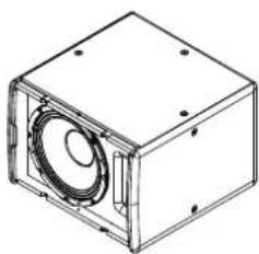
natural_image
Technical line drawing of a rectangular box with a speaker grille and mounting holes (no text or symbols)


SX210

natural_image
Black rectangular electronic device with two side panels and a circular vent grille, no visible text or symbols on the body.Introduction
The SX210 is a slimline dual-driver subwoofer designed for situations that call for a visually unobtrusive enclosure. It can be used singly, stacked or flown via integral M8 inserts and its ultra-compact size makes it ideal for applications where space is limited. It features dual 10" (250mm)/2" (50mm) voice coil drivers and generously sized low frequency ports for reduced air noise.
The SX210 enclosure is constructed from plywood and finished in black textured paint as standard, with white and RAL colour finishes available to special order. An impact-resistant perforated steel grille protects the drivers, and the enclosure has twin ergonomic handles at the rear for easy handling. Rubber feet on the base resist movement and align with recesses in the top surface to assist stacking.
When used with full-range systems, crossover and EQ functions can be performed by the DX0.5 or DX4.0 system controller. The recommended amplifier is the VIA 2502, or VIA 5002 or VIA 5004 depending upon the size of the overall system.
Accessories
M8 eyebolts HTKCT05
Connections

text_image
SX SERIES INPUT 1+, 1, 2+, 3-, LINK THRU LINK 1+, 1, 2+, 2- LINK THRU MODE IN ENGLAND BY MARTIN AUDIO LIMITED CACTURY POINT MELINDA ROAD, CENSARIE BUSINESS FREE, HIGH MTCOME, SUCCE, IPTC 35L. TEL: MAXIMUM RESET 2 PAZ (MAXIMUM SWITCH) www.martin-audio.com Serial No. FOR FURTHER INFORMATION CONSULT THE PRODUCT MANUALThe SX210 has a pair of NL4 connectors on the rear panel. These are wired in parallel and whilst one is nominally labelled 'INPUT' and the other as 'LINK', connection in and out can be made to either connector. Connection to the drive unit(s) is made to pins 1+/-. There is no internal connection to pins 2+/- although these are linked together so can be used for example to carry a mid/top signal and connected to a full range system using a cable wired with reverse connections (pins 2 to pins 1).
Flying SX210
Eyebolts
The SX210 features M8 inserts to allow flown applications using eyebolts. M8 eyebolts suitable for flown systems are available as accessories from Martin Audio. These are cast steel shouldered eye bolts specifically designed and rated for flown applications. If alternative eyebolts are used these must be cast or machined products stamped with their SWL. Formed steel non-shouldered eyebolts commonly available from DIY stores should not be used under any circumstances as they are not sufficiently load-rated for flown applications.

natural_image
Line drawing of a rectangular electronic enclosure with mounting holes and a side panel (no text or symbols)Remove the M8 counter-sunk screws and screw the eyebolts into position. We would recommend four eyebolts and an additional eyebolt as a redundant safety bond. This should be attached to a different point than the other bolts to support the cabinet in the event of the other points failing.
Eyebolts should be connected to a suitably rated fixing point such as a girder clamp or a heavy duty fixing such as a sleeve anchor or similar. They can be linked using suitably rated steel rope or chain and shackles.
Safety note: Flying heavy equipment in public spaces is dangerous and should only be undertaken by suitably qualified and experienced personnel using adequately rated equipment for the task.
Specifications
TYPE Slimline, direct radiating subwoofer
FREQUENCY RESPONSE (1) 50Hz-150Hz ± 3dB, -10dB @ 42Hz
DRIVER 2 x 10" (250mm)/2" (50mm) voice coil, long excursion, ferrite magnet
RATED POWER (2) 500W AES, 2000W peak
RECOMMENDED AMPLIFIER VIA2502/5002/5004
SENSITIVITY (10) 103dB
MAXIMUM SPL (9) 127dB continuous, 133dB peak (half space)
NOMINAL IMPEDANCE 4 ohms
DISPERSION (-6dB) Omnidirectional
CROSSOVER 80-120Hz active
ENCLOSURE Birch/poplar plywood
FINISH Black or white
PROTECTIVE GRILLE Perforated steel
CONNECTORS 2 x NL4
PIN CONNECTIONS (INPUT) +1, -1 (+2, -2 link through)
PIN CONNECTIONS (LINK) +1, -1 (+2, -2 link through)
FITTINGS 16 x M8 inserts, 2 x bar handles
DIMENSIONS (INCL FEET) (W) 720mm x (H) 295mm x (D) 465mm
(W) 28.3ins x (H) 11.6ins x (D) 18.3ins
WEIGHT 20kg (44.1lbs)
Notes
(1) Measured on-axis in half (2pi) space at 2 metres, then referred to 1 metre.
(2) AES Standard ANSI S4.26-1984.
(3) Measured in half (2pi) space at 2 metres with 1 watt input, using band limited pink noise, then referred to 1 metre.
(4) Measured in half (2pi) space at 2 metres using band limited pink noise, then referred to 1 metre.
(5) Measured on-axis in open (4pi) space at 2 metres, then referred to 1 metre.
(6) Measured in open (4pi) space at 2 metres with 1 watt input, using band limited pink noise, then referred to 1 metre.
(7) Measured in open (4pi) space at 2 metres using band limited pink noise, then referred to 1 metre.
(8) Measured in open (4pi) space at 2 metres with 2.83V input, using band limited pink noise, then referred to 1 metre.
(9) Calculated at 1 metre.
(10) Measured in half (2pi) space at 2 metres with 2.83V input, using band limited pink noise, then referred to 1 metre.
Technical Drawing
natural_image
Simple rectangular frame with four circular holes at corners (no text or symbols)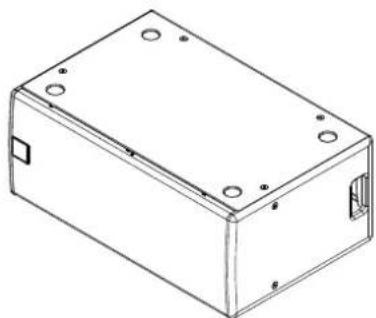
natural_image
Isometric line drawing of a rectangular electronic enclosure with mounting holes and internal structure (no text or symbols)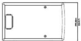

natural_image
Simple line drawing of a rectangular frame with a small square cutout on the left side (no text or symbols)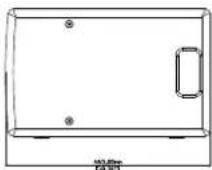
natural_image
Front view of a rectangular electronic device with two side panels and a central display (no text or symbols)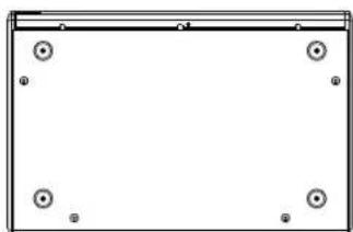
natural_image
Simple rectangular frame with four corner circular holes, no text or symbols presentSX112
natural_image
Black rectangular electronic device with circular vent and speaker grille (no visible text or symbols)Introduction
The SX112 is an ultra-compact direct radiating sub-bass system designed to extend the bandwidth and increase the headroom of full-range loudspeaker models. It features a very efficient 12" (300mm) long-throw bass driver with a high power 3" (75mm) voice coil and generously-sized reflex ports for low noise, high power operation.
With a response of 48Hz-150Hz ± 3dB, the ultra-compact size of the SX112 makes it an ideal partner for ADORN or CDD Series systems where space is at a premium or where the subwoofers need to be hidden. The enclosure is constructed from plywood and has an impact-resistant finish, while the driver is protected by a rigid perforated steel grille, which is pre-curved to withstand physical damage.
Finished in black (RAL9005) or white (RAL9016) as standard with integrated flying points, the SX112 can be also be supplied in any RAL colour to order. When used with full-range systems, crossover and EQ functions can either be performed by the DX0.5 or DX4.0 system controllers.
Accessories
M10 eyebolts HTKCT06
Connections

text_image
SX SERIES INPUT 1+, 1- 2+, 2- LINK THRU LINK 1+, 1- 2+, 2- LINK THRU MODE IN ENGLAND BY MARTIN AUDIO LIMITED CREATURE POINT MULICO ROAD, CENSILEE BUSINESS PRICE, HIGH MTCOME, SUCF, SPD: 35. TEL: +RUBISH DRUST 2 PAE +RAKTER SERIES www.martin-audio.com Serial No. FOR FURTHER INFORMATION CONSULT THE PRODUCT MANUALThe SX112 has a pair of NL4 connectors on the rear panel. These are wired in parallel and whilst one is nominally labelled 'INPUT' and the other as 'LINK', connection in and out can be made to either connector. Connection to the drive unit(s) is made to pins 1+/-. There is no internal connection to pins 2+/- although these are linked together so can be used for example to carry a mid/top signal and connected to a full range system using a cable wired with reverse connections (pins 2 to pins 1).
Flying SX112
Eyebolts
The SX112 features M10 inserts to allow flown applications using eyebolts. M10 eyebolts suitable for flown systems are available as accessories from Martin Audio. These are cast steel shouldered eye bolts specifically designed and rated for flown applications. If alternative eyebolts are used these must be cast or machined products stamped with their SWL. Formed steel non-shouldered eyebolts commonly available from DIY stores should not be used under any circumstances as they are not sufficiently load-rated for flown applications.

natural_image
Line drawing of a rectangular electronic device with mounting holes and a handle (no text or symbols)Remove the M10 counter-sunk screws and screw the eyebolts into position. We would recommend three eyebolts and an additional eyebolt as a redundant safety bond. This should be attached to a different point than the other bolts to support the cabinet in the event of the other points failing.
Eyebolts should be connected to a suitably rated fixing point such as a girder clamp or a heavy duty fixing such as a sleeve anchor or similar. They can be linked using suitably rated steel rope or chain and shackles.
Safety note: Flying heavy equipment in public spaces is dangerous and should only be undertaken by suitably qualified and experienced personnel using adequately rated equipment for the task.
Specifications
TYPE Ultra-Compact, single driver, direct radiating subwoofer
FREQUENCY RESPONSE (1) 48Hz-150Hz ± 3dB, -10dB @ 35Hz
DRIVER 1 x 12" (300mm)/3" (75mm) voice coil, long excursion, ferrite magnet, waterproof cone
RATED POWER (2) 400W AES, 1600W peak
RECOMMENDED AMPLIFIER iK81/VIA2502/5002/5004
SENSITIVITY (10) 100dB
MAXIMUM SPL (9) 126dB continuous, 132dB peak (half space)
NOMINAL IMPEDANCE 8 ohms
DISPERSION (-6dB) Omnidirectional
CROSSOVER 80-120Hz active
ENCLOSURE Plywood
FINISH Black or white
PROTECTIVE GRILLE Perforated steel
CONNECTORS 2 x NL4
PIN CONNECTIONS (INPUT) +1, -1 (+2, -2 link through)
PIN CONNECTIONS (LINK) +1, -1 (+2, -2 link through)
FITTINGS 12 x M10 inserts
DIMENSIONS (INCL FEET) (W) 487mm x (H) 385mm x (D) 410mm
(W) 19.2ins x (H) 15.2ins x (D) 16.1ins
WEIGHT 21.5kg (47.3lbs)
Notes
(1) Measured on-axis in half (2pi) space at 2 metres, then referred to 1 metre.
(2) AES Standard ANSI S4.26-1984.
(3) Measured in half (2pi) space at 2 metres with 1 watt input, using band limited pink noise, then referred to 1 metre.
(4) Measured in half (2pi) space at 2 metres using band limited pink noise, then referred to 1 metre.
(5) Measured on-axis in open (4pi) space at 2 metres, then referred to 1 metre.
(6) Measured in open (4pi) space at 2 metres with 1 watt input, using band limited pink noise, then referred to 1 metre.
(7) Measured in open (4pi) space at 2 metres using band limited pink noise, then referred to 1 metre.
(8) Measured in open (4pi) space at 2 metres with 2.83V input, using band limited pink noise, then referred to 1 metre.
(9) Calculated at 1 metre.
(10) Measured in half (2pi) space at 2 metres with 2.83V input, using band limited pink noise, then referred to 1 metre.
Technical Drawing

natural_image
Simple line drawing of a rectangular frame with four circular holes at corners (no text or symbols)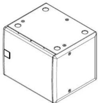
natural_image
Line drawing of a rectangular box with mounting holes and a side panel (no text or symbols)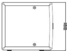
natural_image
Simple line drawing of a rectangular frame with two circular holes and a dimension label (no text or symbols beyond measurement lines)
natural_image
Simple line drawing of a rectangular frame with a small square cutout on the side (no text or symbols)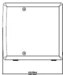
natural_image
Simple line drawing of a rectangular box with two circular holes and a base, no text or symbols present.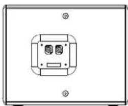
natural_image
Front view of a rectangular electronic device with a central button and two ports, no visible text or symbols.
natural_image
Simple line drawing of a rectangular frame with four circular holes at the corners (no text or symbols)SX212
natural_image
Black rectangular electronic device with two side panels and ventilation grille (no visible text or symbols)Introduction
With twin high-efficiency 12" (300mm)/3" (75mm) voice coil long-throw bass drivers and optimally-sized reflex ports to minimise air noise, the SX212 is the perfect sub-bass where low frequency extension and impact is required from a very compact, unobtrusive, low-profile enclosure.
The SX212 is designed to be used with full-range loudspeaker systems and extends the low frequency operating range of the combined system down to 40Hz. The enclosure is constructed from plywood and is internally-braced to reduce energy transmission to the enclosure panels and baffle. Its perforated steel grille is pre-curved to withstand damage and it can be supplied fitted with optional flying points.
Finished in black (RAL9005) or white (RAL9016) as standard with integrated flying points, the SX212 can be also be supplied in any RAL colour to order. When used with full-range systems, crossover and EQ functions can either be performed by the DX0.5 or DX4.0 system controllers.
Accessories
M10 eyebolts HTKCT06
Connections

text_image
SX SERIES INPUT 1+, 1, 2+, 3-, LINK THRU LINK 1+, 1, 2+, 3-, LINK THRU MODE IN ENGLAND BY MARTIN AUDIO LIMITED CHANTOUR POINT MALLING ROAD, CHINESE BUSINESS PRICE, HIGH MTCOME, RACE, SPTD: 9L. TEL: (RASSIGN) RESET / PIN: (RASSIGN) CODES www.martin-audio.com Serial No. FOR FURTHER INFORMATION CONSULT THE PRODUCT MANUALThe SX212 has a pair of NL4 connectors on the rear panel. These are wired in parallel and whilst one is nominally labelled 'INPUT' and the other as 'LINK', connection in and out can be made to either connector. Connection to the drive unit(s) is made to pins 1+/-. There is no internal connection to pins 2+/- although these are linked together so can be used for example to carry a mid/top signal and connected to a full range system using a cable wired with reverse connections (pins 2 to pins 1).
Flying SX212
Eyebolts
The SX212 features M10 inserts to allow flown applications using eyebolts. M10 eyebolts suitable for flown systems are available as accessories from Martin Audio. These are cast steel shouldered eye bolts specifically designed and rated for flown applications. If alternative eyebolts are used these must be cast or machined products stamped with their SWL. Formed steel non-shouldered eyebolts commonly available from DIY stores should not be used under any circumstances as they are not sufficiently load-rated for flown applications.

natural_image
Line drawing of a rectangular electronic device with mounting holes and internal components (no text or symbols)Remove the M10 counter-sunk screws and screw the eyebolts into position. We would recommend three eyebolts and an additional eyebolt as a redundant safety bond. This should be attached to a different point than the other bolts to support the cabinet in the event of the other points failing.
Eyebolts should be connected to a suitably rated fixing point such as a girder clamp or a heavy duty fixing such as a sleeve anchor or similar. They can be linked using suitably rated steel rope or chain and shackles.
Safety note: Flying heavy equipment in public spaces is dangerous and should only be undertaken by suitably qualified and experienced personnel using adequately rated equipment for the task.
Specifications
TYPE Ultra-Compact, dual-driver, direct radiating subwoofer
FREQUENCY RESPONSE (1) 48Hz-150Hz ± 3dB, -10dB @ 35Hz
DRIVER 2 x 12" (300mm)/3" (75mm) voice coil, long excursion, ferrite magnet, waterproof cone
RATED POWER (2) 800W AES, 3200W peak
RECOMMENDED AMPLIFIER iK42/VIA5002/5004
SENSITIVITY (10) 106dB
MAXIMUM SPL (9) 132dB continuous, 138dB peak (half space)
NOMINAL IMPEDANCE 4 ohms
DISPERSION (-6dB) Omnidirectional
CROSSOVER 80-120Hz active
ENCLOSURE Plywood
FINISH Black or white
PROTECTIVE GRILLE Perforated steel
CONNECTORS 2 x NL4
PIN CONNECTIONS (INPUT) +1, -1 (+2, -2 link through)
PIN CONNECTIONS (LINK) +1, -1 (+2, -2 link through)
FITTINGS 12 x M10 inserts
DIMENSIONS (INCL FEET) (W) 872mm x (H) 385mm x (D) 437mm
(W) 34.3ins x (H) 15.2ins x (D) 17.2ins
WEIGHT 39kg (86lbs)
Notes
(1) Measured on-axis in half (2pi) space at 2 metres, then referred to 1 metre.
(2) AES Standard ANSI S4.26-1984.
(3) Measured in half (2pi) space at 2 metres with 1 watt input, using band limited pink noise, then referred to 1 metre.
(4) Measured in half (2pi) space at 2 metres using band limited pink noise, then referred to 1 metre.
(5) Measured on-axis in open (4pi) space at 2 metres, then referred to 1 metre.
(6) Measured in open (4pi) space at 2 metres with 1 watt input, using band limited pink noise, then referred to 1 metre.
(7) Measured in open (4pi) space at 2 metres using band limited pink noise, then referred to 1 metre.
(8) Measured in open (4pi) space at 2 metres with 2.83V input, using band limited pink noise, then referred to 1 metre.
(9) Calculated at 1 metre.
(10) Measured in half (2pi) space at 2 metres with 2.83V input, using band limited pink noise, then referred to 1 metre.
Technical Drawing
SXF115
natural_image
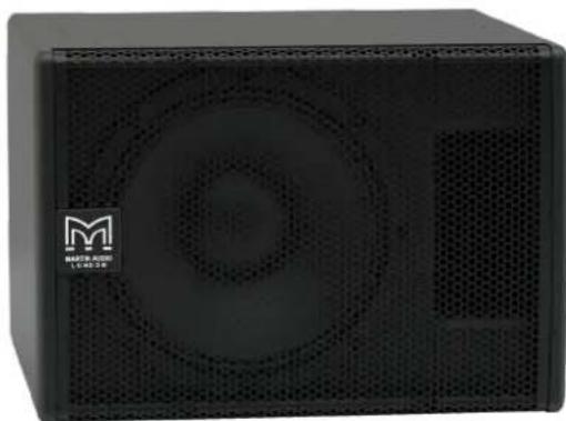
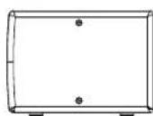
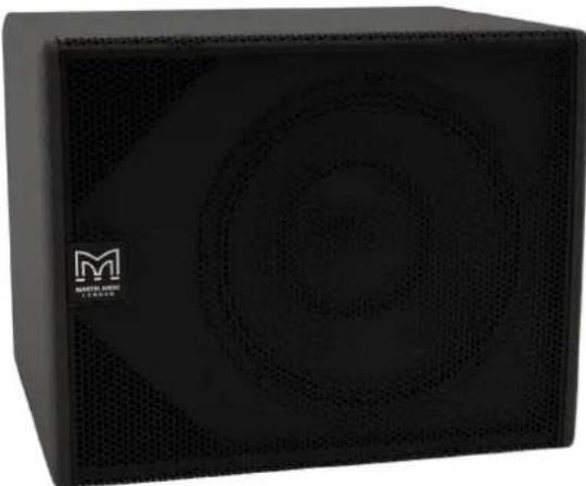
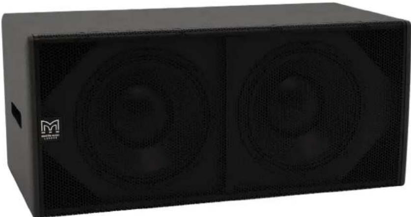
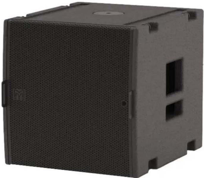
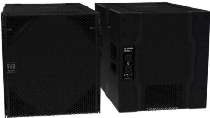
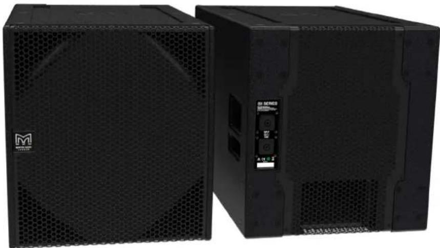
Exterior view of a black plastic enclosure with perforated panel and mounting holes (no text or symbols visible)Introduction
The SXF115 is a passive subwoofer designed to extend the performance of Martin Audio WPM and MLA Mini systems down to 42Hz. Featuring a powerful, long excursion 15" (380mm)/4" (100mm) voice coil driver in a very compact bass reflex enclosure, it can be flown as part of a WPM or MLA Mini array, or ground-stacked separately.
The design of the 15" driver maximises output while minimising power compression and distortion, and four reflex ports reduce air noise at very high output levels. The SXF115 enclosure is constructed from multi-laminate birch ply, finished with a durable polyurethane coating and equipped with a perforated steel grille, skids and twin bar handles. An M2O threaded fitting in the top surface facilitates pole-mounting of up to 4 WPM or MLA Mini enclosures.
Being a passive subwoofer, the SXF115 is ideal for flown WPM or MLA Mini fixed installations where ground-based, rack-mount amplification is preferred — either for ease of servicing, increased IP protection, or reduced visible cabling in the air.
When used with a WPM or MLA Mini array, Martin Audio iKON amplifiers or the MSX rack-mount power plant respectively deliver the correct drive characteristics to the SXF115, with onboard DSP presets for a variety of system configurations. Cardioid operation can be achieved by arranging the SXF115 in forward and rear-facing pairs.
By adding the input board cover accessory, the subwoofer is fully weather resistant and suitable for permanent outdoor usage.
Accessories
Install flying frame ASF20054
Touring flying frame ASF20064 (includes inclinometer & shackles)
Transition grid WPMMSXGRID
Ground stack base plate ASF20062
Wheelboard and cover ASF17025
Wind-up pole ASF20071
Weather kit WRKIT
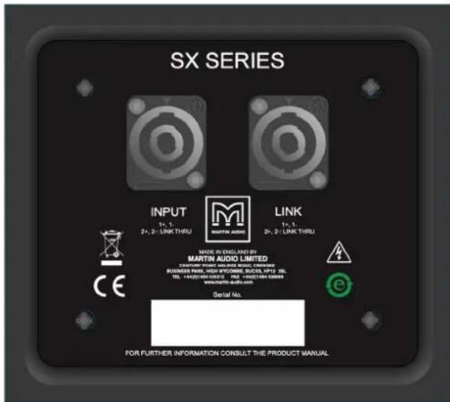
Connections

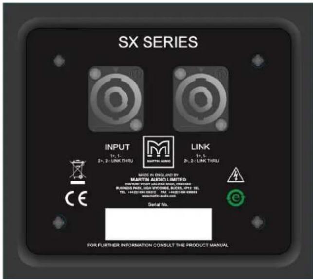
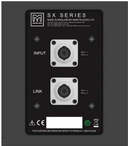
text_image
SX SERIES INPUT 1+, 1- 2+, 2- LINK THRU LINK 1+, 1- 2+, 2- LINK THRU MODE IN ENGLARD BY MARTIN AUDIO LIMITED CAPTURE POINT MULINA ROUND, CENSILE BUSINESS FREE, HIGH MTCOME, SUCF, IPTI 35L. TEL: (RASSIGN) DNET 2 PAG (RASSIGN) 0003 www.martin-audio.com Serial No. FOR FURTHER INFORMATION CONSULT THE PRODUCT MANUALThe SXF115 has a pair of NL4 connectors on the rear panel. These are wired in parallel and whilst one is nominally labelled 'INPUT' and the other as 'LINK', connection in and out can be made to either connector. Connection to the drive unit(s) is made to pins 1+/-. There is no internal connection to pins 2+/- although these are linked together so can be used for example to carry a mid/top signal and connected to a full range system using a cable wired with reverse connections (pins 2 to pins 1).
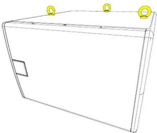
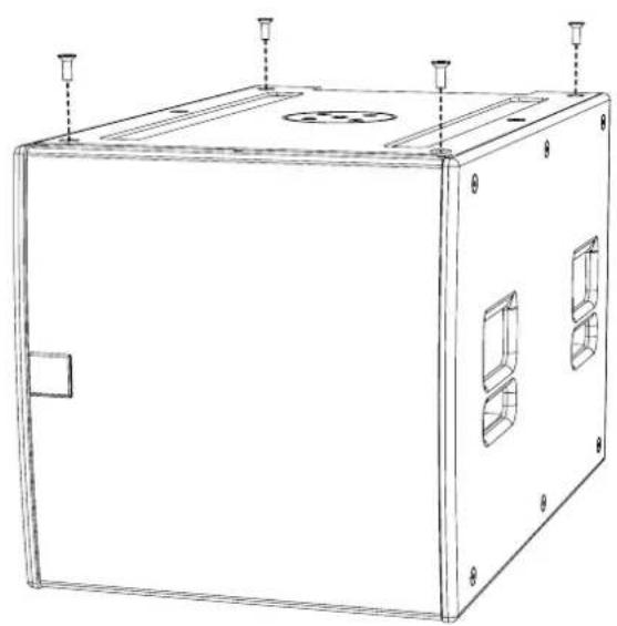
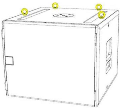
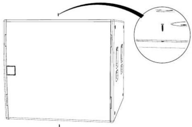
Flying SXF115
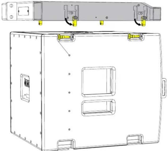
The SXF115 may be flown using the ASF20054 or ASF20064 flying frames which are also used with the MLA Mini system. The ASF20054 is designed for installations, whilst the ASF20064 is fitted with an inclinometer sensor and supplied with shackles making it suitable for touring applications. Deployment of the system is identical with both versions of the flying frame.
With the sub on the floor under the desired position for its final deployment, attach the frame to the chain or motor hoist(s) and raise so it is just above the SXF115. Remove the four flying pins on the bottom of the flying frame to release the drop-down rigging links.
natural_image
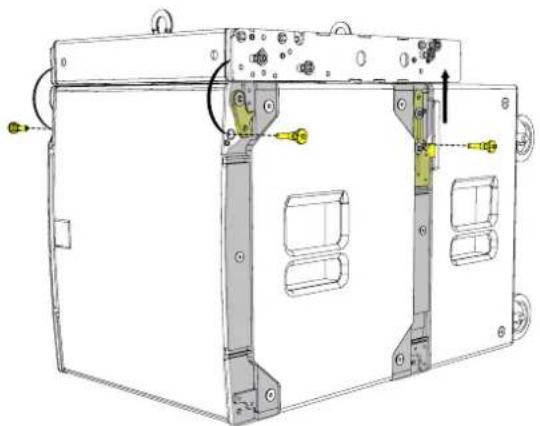
Technical line drawing of a device enclosure with mounting holes and internal compartments (no text or symbols)Lower the flying frame onto the sub guiding the four links into the corresponding slots in the top of the sub. Insert flying pins into the four rigging brackets on the sub to lock it to the frame. Ensure that the central button on the flying pin has popped out to ensure that the array is safe.

natural_image
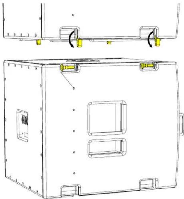
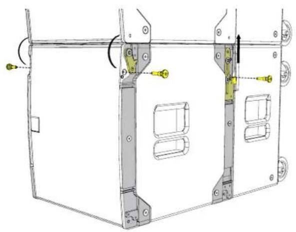
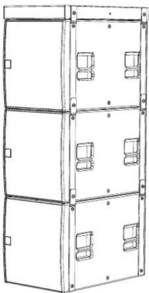
Technical line drawing of a rectangular electronic device with mounting holes and internal compartments (no text or symbols)If more subs are to be linked under the first, raise the height of the first sub so you can position a second sub directly under the first. Remove the flying pins in the bottom drop-down rigging links in the first sub and lower it onto the second ensuring that the rigging links engaging all four rigging slots in the second sub exactly as you did with the frame and first cabinet.
natural_image
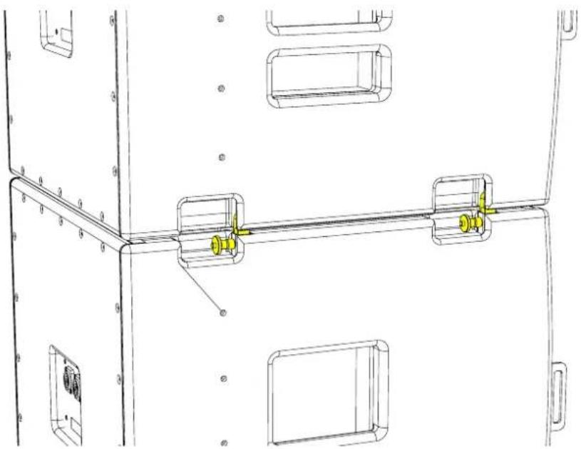
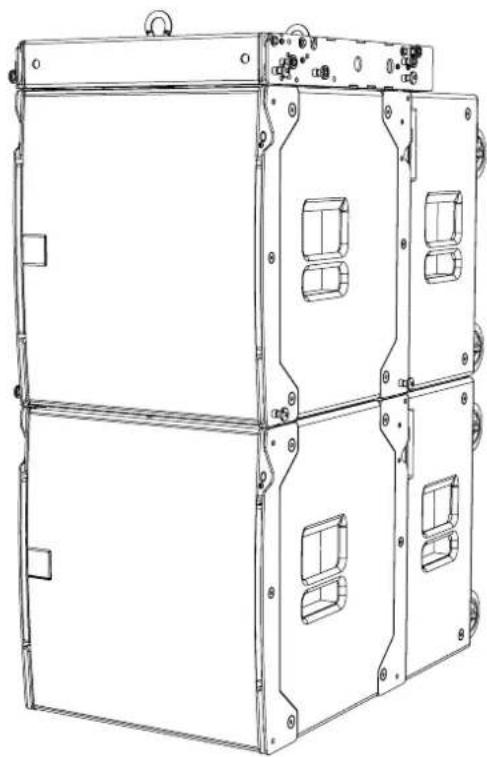
Technical line drawing of a rectangular electronic device with mounting holes and internal compartments (no text or symbols)Insert the four flying pins into the rigging brackets on the second SXF115 ensuring that the pins are correctly engaged.
natural_image
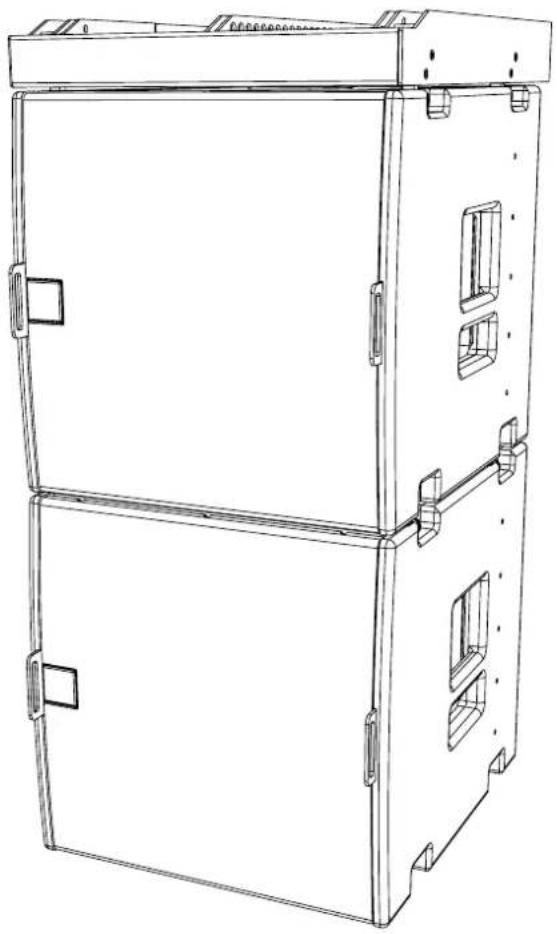
Technical line drawing of a mechanical assembly with mounting brackets and a central shaft (no text or symbols)More cabinets can be added as required or transition frames connected to enable flying of either MLA Mini or WPM arrays under the SXP115. For more details see the User Guides for MLA Mini and WPM.
natural_image
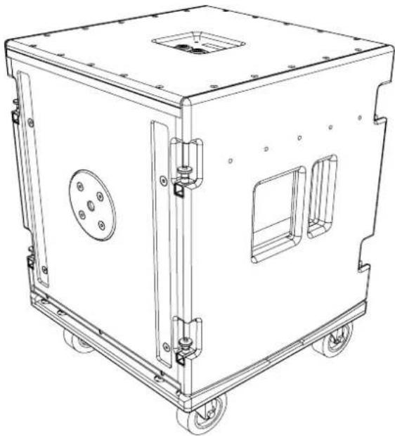
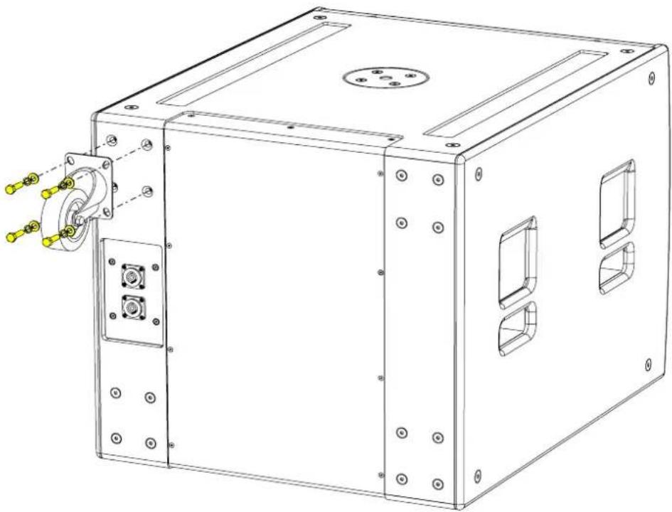
Line drawing of a multi-tiered industrial enclosure or storage unit with mounting brackets and doorways (no text or symbols)Wheelboard
The SXF115 uses a front mounted wheelboard and travels face-down. The transit cover drops over the top of the cabinet once it is on the wheelboard.
natural_image
Technical line drawing of a mechanical device with wheels and mounting holes (no text or symbols)Weather Kit
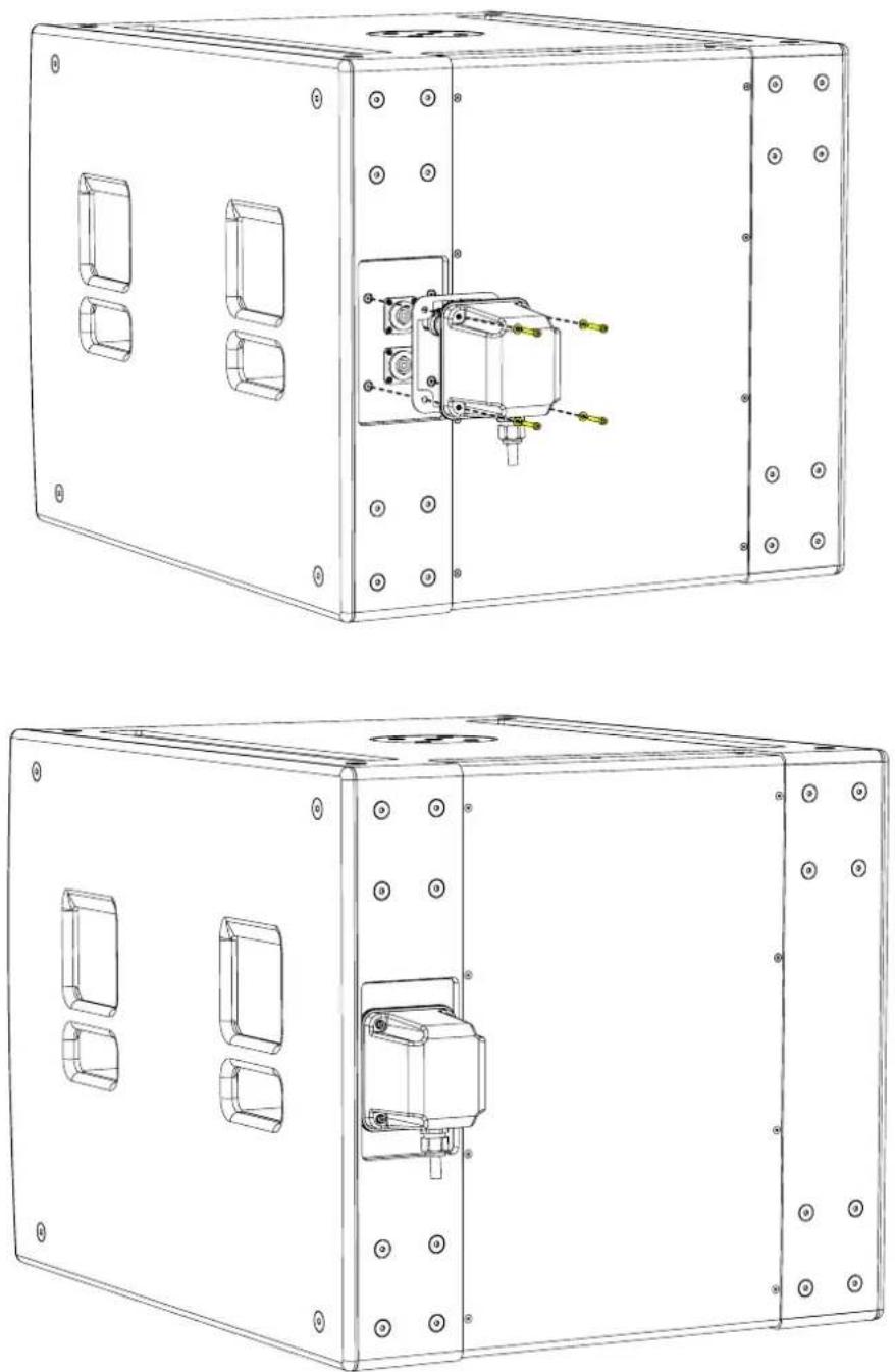
The WRKIT for non-powered SX Series subwoofers is a glanded cover which fits over the connection panel to prevent water ingress protecting the NL4 speaker connection.
The cable entry may be through one of two knock-out positions depending the angle from which you wish the cable to enter. First remove the knock-out blank that you wish to use and fit the cable gland in position. Note that to use the WRKIT it is necessary to remove the NL4 connector from your speaker cable so the cable can be fed through the cable gland. Once the cable has been threaded through the gland the NL4 can be re-attached.
Remove the four counter-sunk screws in the connector panel and position the cover on the connector panel. Connect the NL4 to the input connector and position the cover, pulling the slack in the speaker cable as you lower the cover in position. Secure the cover using the four M4 x 25 cap socket screws and fibre washers. Finally tighten the gland to ensure a waterproof seal.

natural_image
Technical line drawing of a mechanical enclosure with internal components and mounting holes (no text or symbols)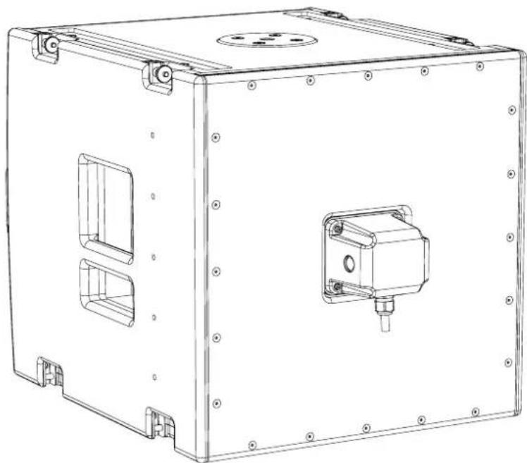
natural_image
Technical line drawing of a rectangular electronic enclosure with mounting holes and internal compartments (no text or symbols)Specifications
TYPE Compact, single driver, direct radiating subwoofer
FREQUENCY RESPONSE (1) 50Hz-150Hz ± 3dB, -10dB @ 42Hz
DRIVER 1 x 15" (300mm)/4" (100mm) voice coil, ultra-long excursion, ferrite magnet
RATED POWER (2) 800W AES, 3200W peak
RECOMMENDED AMPLIFIER iK42/81
SENSITIVITY (10) 103dB
MAXIMUM SPL (9) 136dB continuous
NOMINAL IMPEDANCE 8 ohms
DISPERSION (-6dB) Omnidirectional
CROSSOVER 80-120Hz active
ENCLOSURE Multi-laminate birch plywood
FINISH Textured PU coating
PROTECTIVE GRILLE Perforated steel
CONNECTORS 2 x NL4
PIN CONNECTIONS (INPUT) +1, -1 (+2, -2 link through)
PIN CONNECTIONS (LINK) +1, -1 (+2, -2 link through)
| FITTINGS | Two skids on base, matching channels on top |
| M20 top-mounted thread plate for pole mounting | |
| Integral flyware for suspension of up to four SXF115 | |
| Large bar handle on each side | |
| Two front-mounting latch plates for wheelboard | |
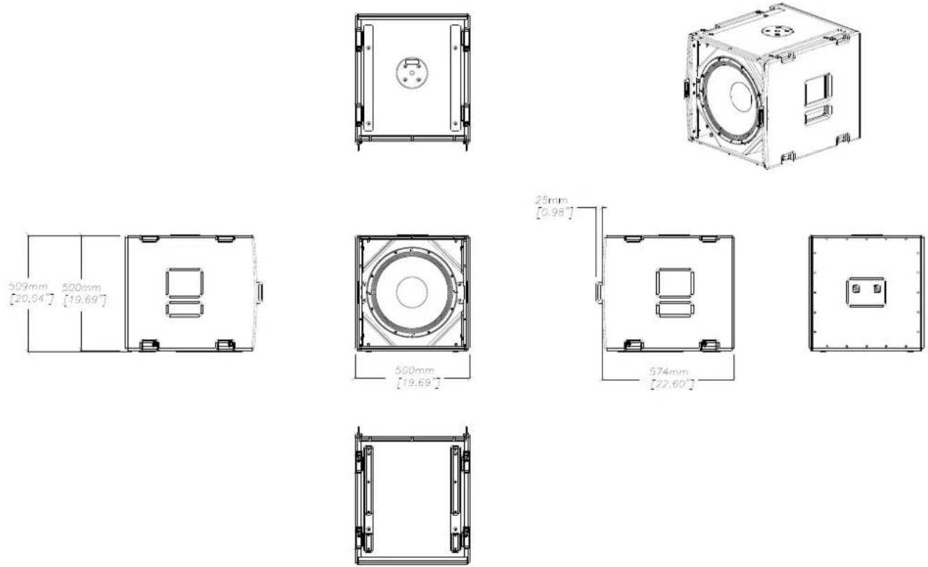
| DIMENSIONS (INCL FEET) | (W) 500mm x (H) 510mm x (D) 575mm (725mm incl wheelboard) |
| (W) 19.7in x (H) 20.1in x (D) 22.6in (28.5in incl wheelboard) | |
| WEIGHT | 45kg (99lbs) |
| 52kg (115lbs) incl wheelboard |
Notes
(1) Measured on-axis in half (2pi) space at 2 metres, then referred to 1 metre.
(2) AES Standard ANSI S4.26-1984.
(3) Measured in half (2pi) space at 2 metres with 1 watt input, using band limited pink noise, then referred to 1 metre.
(4) Measured in half (2pi) space at 2 metres using band limited pink noise, then referred to 1 metre.
(5) Measured on-axis in open (4pi) space at 2 metres, then referred to 1 metre.
(6) Measured in open (4pi) space at 2 metres with 1 watt input, using band limited pink noise, then referred to 1 metre.
(7) Measured in open (4pi) space at 2 metres using band limited pink noise, then referred to 1 metre.
(8) Measured in open (4pi) space at 2 metres with 2.83V input, using band limited pink noise, then referred to 1 metre.
(9) Calculated at 1 metre.
(10) Measured in half (2pi) space at 2 metres with 2.83V input, using band limited pink noise, then referred to 1 metre.
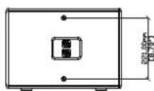
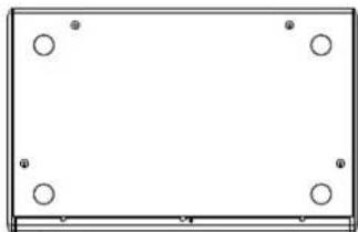
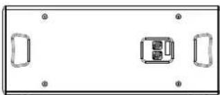
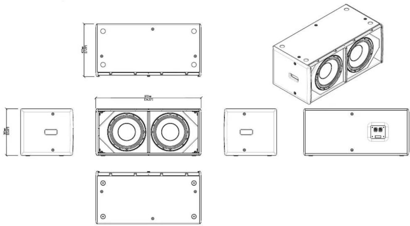
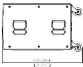
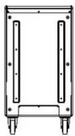
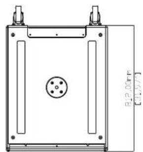
Technical Drawing
SXCF115
natural_image
Two black industrial server units with ventilation grilles and ventilation grilles, no visible text or symbols on the equipment.Introduction
Designed for touring sound and installations, the SXCF115 is a compact, high performance cardioid subwoofer. It features a 15" (380mm) forward facing driver and a 12" (300mm) rear facing driver, each driven independently by separate amplifier channels and DSP. Each driver has its own chamber with optimised bass reflex porting.
This arrangement produces a cardioid dispersion pattern which maximises the front radiation and reduces unwanted radiation behind the subwoofer.
The recommended iK42 amplifier optimises the DSP parameters for front and rear drivers to maximise the rear rejection — from 21dB at 44Hz to 28dB at 75Hz. This keeps low frequencies away from stages, turntables and walls as well as reducing reverberant energy in the room, greatly improving the system's low frequency response accuracy and impact.
In front of the enclosure, the output from the two drivers is additive, giving an extra 2dB of output when compared with a conventional 1 x 15" subwoofer.
Accessories
M10 eyebolts HTKCT06
Transit cover SXCF115TC
Castor kit WHEELKIT
Wind-up pole ASF20071
Weather kit WRKIT
Flying Strips FKIT550
Connections

text_image
SX SERIES Note: In Project by MATERIALS, MODELED CLOSURE SWITCH (FLUER) ROAD, CLOURED IN CHASED SWITCH (LPG) ROAD, 125.0 MHz 456 MHz TEN: 125.0 MHz 456 MHz TEN: 125.0 MHz 456 MHz PROPOSED SWITCH INPUT PIN 1+, 1- PIN 2+, 3- LINK CE Serial No.The SXCF115 features two drivers, a 15" front facing driver and the rear-facing 12" driver used to achieve a cardioid response. Connection is made via two NL4 connectors which are wired in parallel. Although these are nominally labelled 'INPUT' and 'LINK', either connector can be used to connect to the sub or to link out to a second speaker.
The Front 15" driver is connected to pins 1+/-, the rear 12" driver to pins 2+/-. A 4-core NL4 cable must be used.
If using the recommended iK42 amplifier, connection can be made to output NL4 1 or 3 as these also carry the output signal from channels 2 and 4 respectively to power both drivers.
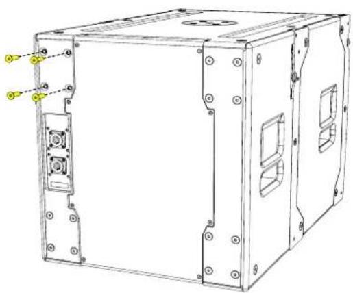
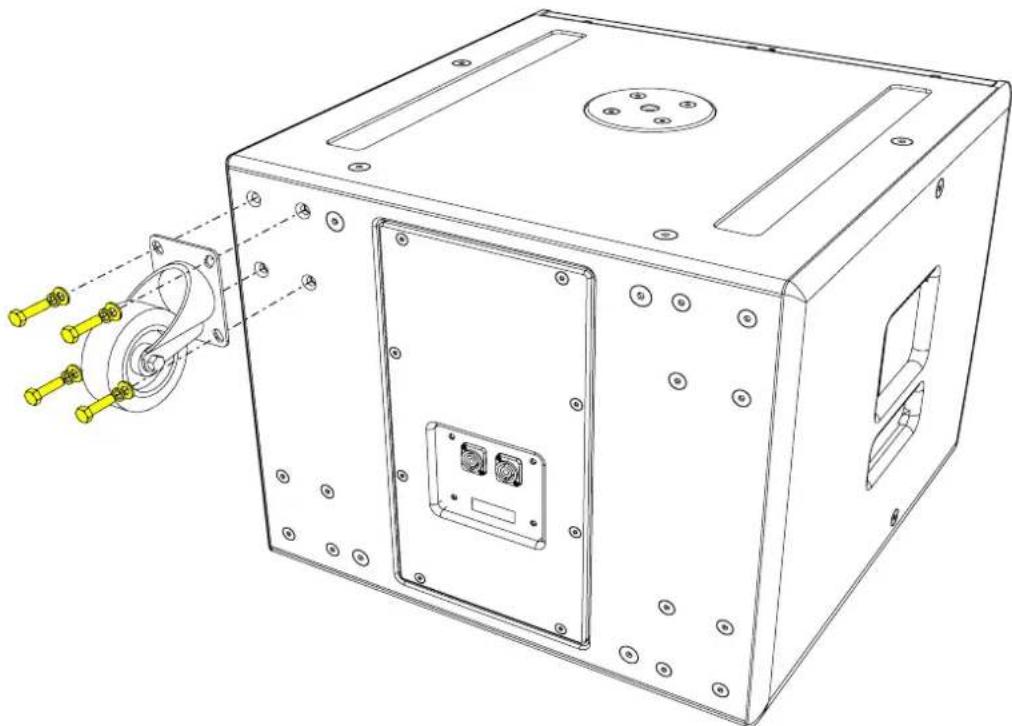
Castors
Accessories
- WHEELKIT
1 x WHEELKIT is required for each cabinet. The WHEELKIT consists of
- 4 x Casters
- 16 x M8 x 30 Hex Bolts
- 16 x M8 Washers
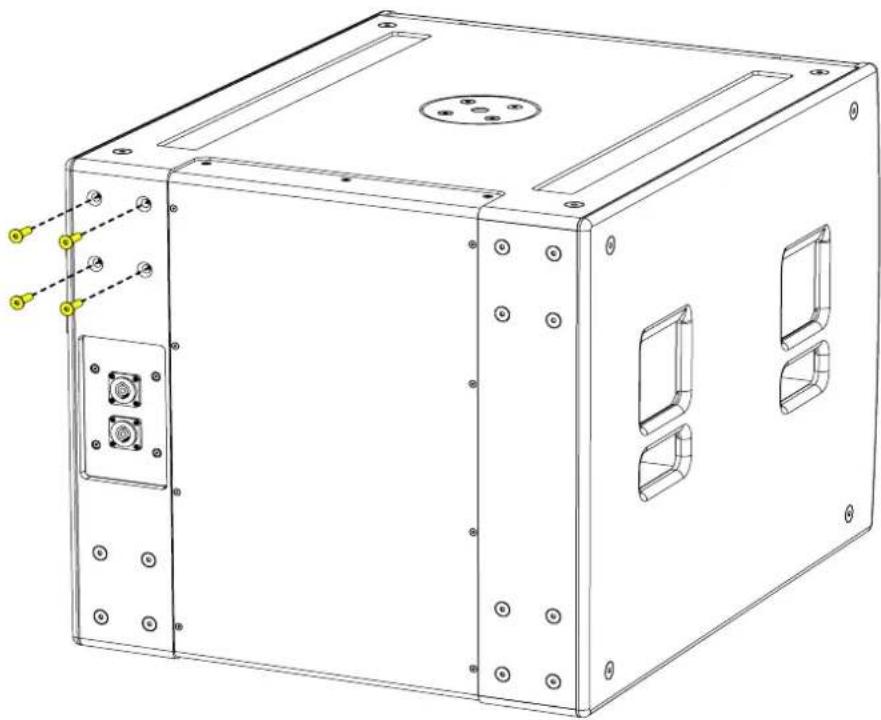
To fit the castors, remove the M8 counter-sunk screws from the rear of the enclosure.
natural_image
Technical line drawing of a mechanical device casing with mounting holes and internal compartments (no text or symbols)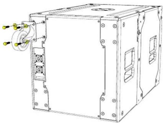
natural_image
Technical line drawing of a mechanical device with mounting holes and a central rotating component (no text or symbols)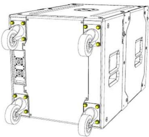
natural_image
Technical line drawing of a mechanical device with wheels and mounting holes (no text or symbols)Flying SXCF115
Accessories
- 4 x HTKCT06
• Additional HTKCT06 M10 eyebolts can be used to implement a secondary safety
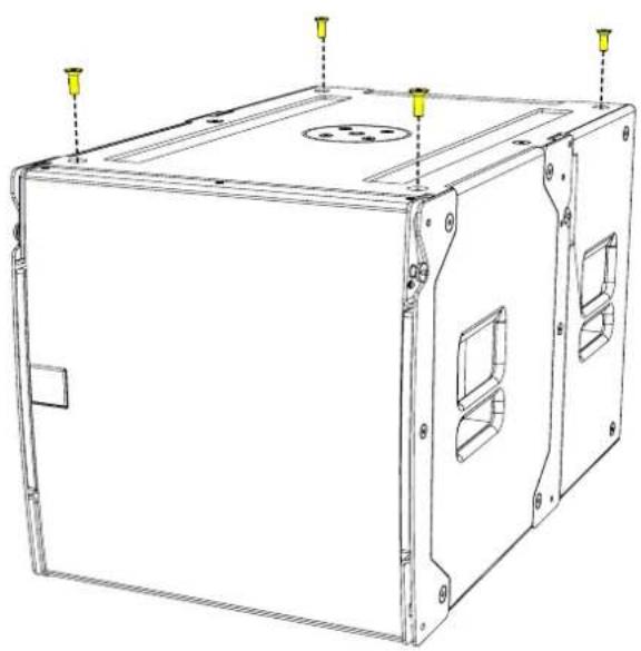
Eyebolts
The SXCF115 features M10 inserts to allow flown applications using eyebolts. M10 eyebolts suitable for flown systems are available as accessories from Martin Audio.
Remove the M10 counter-sunk screws and screw the eyebolts into position. We would recommend four eyebolts and an additional eyebolt as a redundant safety bond. This should
ATTENTION! - Only 1 x SXCF115 can be suspended using this method
natural_image
Technical line drawing of a rectangular electronic device with mounting holes and internal compartments (no text or symbols)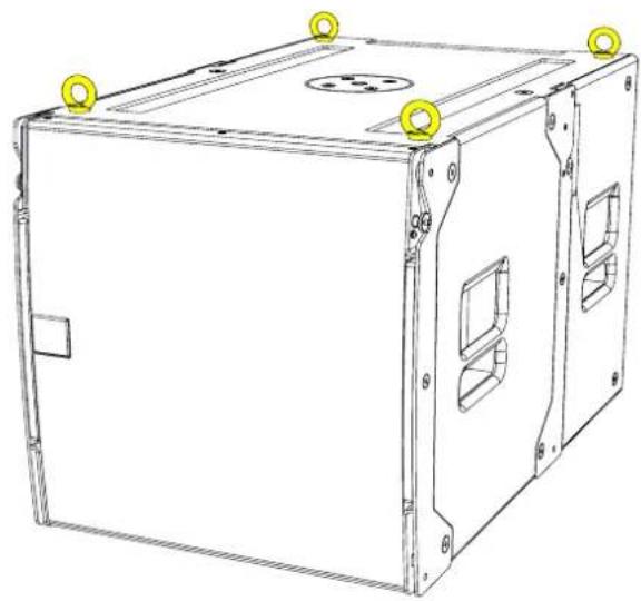
natural_image
Technical line drawing of a rectangular electronic device with mounting holes and internal compartments (no text or symbols)Eyebolts should be connected to a suitably rated fixing point such as a girder clamp or a heavy duty fixing such as a sleeve anchor or similar. They can be linked using suitably rated steel rope or chain and shackles.
Safety note: Flying heavy equipment in public spaces is dangerous and should only be undertaken by suitably qualified and experienced personnel using adequately rated equipment for the task
Flown Arrays SXCF115
For permanent flown SXCF115 array applications, the following accessories are needed. A maximum of X SXCF115 enclosures can be flown using this method.
Accessories
- WPMSXGRIDT
- SXCF115
Position the WPMSXGRIDT on top of the SXCF115 cabinet
Remove the pins from the from SXCF115 to release the

natural_image
Technical line drawing of a device casing with internal compartments and mounting holes (no text or symbols)
natural_image
Technical line drawing of a mechanical device with mounting holes and internal compartments (no text or symbols)Rotate the front links and lift the rear links to align with the pin holes in the WPMSXGRIDT.
natural_image
Technical line drawing of a mechanical housing or enclosure with internal components and directional arrows (no text or symbols)Replace the pins to link and lock the SXCF115 securely to the WPMGRIDT

natural_image
Technical line drawing of a server rack unit with mounting holes and internal compartments (no text or symbols)
natural_image
Technical line drawing of a mechanical device housing with mounting brackets and internal compartments (no text or symbols)Place an SXCF115 on top and align with cabinet below. Release the pins from the cabinet below and rotate the front links. Slide the rear links up to the cabinet above.
Lock the pins in the cabinet above to secure.
natural_image
Technical line drawing of a mechanical assembly with no visible text or symbols
natural_image
Technical line drawing of a mechanical housing or enclosure with mounting brackets and internal compartments (no text or symbols)
natural_image
Technical line drawing of a mechanical housing or enclosure with mounting brackets and internal compartments (no text or symbols)Repeat the process for the desired number of cabinets for the array.
natural_image
Technical line drawing of a multi-tiered industrial or electronic device unit with mounting holes and internal compartments (no text or symbols)Safety note: Flying heavy equipment in public spaces is dangerous and should only be undertaken by suitably qualified and experienced personnel using adequately rated equipment for the task
Specifications
TYPE Compact, cardioid subwoofer
FREQUENCY RESPONSE (1) 44Hz - 150Hz ±3dB, -10dB @ 36Hz
DRIVERS 15" (380mm)/4" (100mm) voice coil, long excursion, ferrite magnet,
waterproof cone
12" (300mm)/4" (100mm) voice coil, long excursion,
neodymium magnet, waterproof cone
RATED POWER (2) 15": 1000W AES, 4000W peak
12": 800W AES, 3200W peak
SENSITIVITY (10) 101dB
MAXIMUM SPL (9) 137dB peak
NOMINAL IMPEDANCE 15": 8 ohms
12": 8 ohms
DISPERSION (-6dB) Cardioid
ENCLOSURE Multi-laminate birch ply
FINISH Textured black paint
PROTECTIVE GRILLE Black HEX perforated steel
CONNECTORS 2 x NL4
PIN CONNECTIONS (INPUT) 15": +1, -1; 12": +2, -2
PINS CONNECTIONS (LINK) 15": +1, -1; 12": +2, -2
FITTINGS Two skids on base, with mating channels on top
M20 top-mounted thread plate for pole mounting
Two bar handles on each side
16 x M8 inserts for optional castors
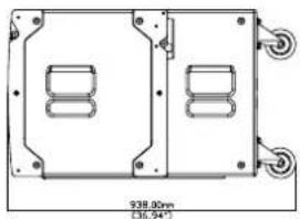
DIMENSIONS (INCL SKIDS) (W) 500mm x (H) 552mm x (D) 810mm (938mm incl castors)
(W) 19.69in x (H) 21.71in x (D) 31.90in (36.94in incl castors)
WEIGHT 61.5Kg (136lbs), 65Kg (143lbs) incl castors
Notes
(1) Measured on-axis in half (2pi) space at 2 metres, then referred to 1 metre.
(2) AES Standard ANSI S4.26-1984.
(3) Measured in half (2pi) space at 2 metres with 1 watt input, using band limited pink noise, then referred to 1 metre.
(4) Measured in half (2pi) space at 2 metres using band limited pink noise, then referred to 1 metre.
(5) Measured on-axis in open (4pi) space at 2 metres, then referred to 1 metre.
(6) Measured in open (4pi) space at 2 metres with 1 watt input, using band limited pink noise, then referred to 1 metre.
(7) Measured in open (4pi) space at 2 metres using band limited pink noise, then referred to 1 metre.
(8) Measured in open (4pi) space at 2 metres with 2.83v input, using band limited pink noise, then referred to 1 metre.
(9) Calculated at 1 metre.
(10) Measured in half (2pi) space at 2 metres with 2.83V input, using band limited pink noise, then referred to 1 metre.
Technical Drawing

natural_image
Technical drawing of a rectangular enclosure with internal components and a central circular component (no text or symbols)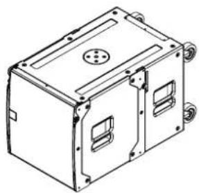
natural_image
Technical line drawing of an open industrial enclosure with mounting holes and ventilation slots (no text or symbols)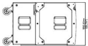
natural_image
Technical line drawing of a mechanical component with mounting holes and internal compartments (no text or symbols)
natural_image
Technical drawing of a mechanical housing or enclosure with two internal compartments and mounting holes (no text or symbols)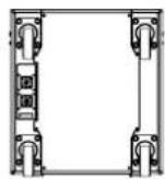

natural_image
Pure mechanical component diagram without any text, numbers, or symbolsSXCF115
SXC115
natural_image
Two black server units with ventilation grilles and ventilation grilles, no visible text or symbols on the surfaces.Introduction
Designed for touring sound and installations, the SXC115 is a compact, high performance cardioid subwoofer. It features a 15" (380mm) forward facing driver and a 12" (300mm) rear facing driver, each driven independently by separate amplifier channels and DSP. Each driver has its own chamber with optimised bass reflex porting.
This arrangement produces a cardioid dispersion pattern which maximises the front radiation and reduces unwanted radiation behind the subwoofer.
The recommended iK42 amplifier optimises the DSP parameters for front and rear drivers to maximise the rear rejection — from 21dB at 44Hz to 28dB at 75Hz. This keeps low frequencies away from stages, turntables and walls as well as reducing reverberant energy in the room, greatly improving the system's low frequency response accuracy and impact.
In front of the enclosure, the output from the two drivers is additive, giving an extra 2dB of output when compared with a conventional 1 x 15" subwoofer.
Accessories
M10 eyebolts HTKCT06
Transit cover SXC115TC
Castor kit WHEELKIT
Wind-up pole ASF20071
Weather kit WRKIT
Flying Grid SXC115GRIDI
Flying Strips FKIT550
Connections

text_image
SX SERIES Input PIN 1+, 1- PIN 2+, 2- LINK SEMI CE e Serial No.The SXC118 features two drivers, a 15" front facing driver and the rear-facing 12" driver used to achieve a cardioid response. Connection is made via two NL4 connectors which are wired in parallel. Although these are nominally labelled 'INPUT' and 'LINK', either connector can be used to connect to the sub or to link out to a second speaker.
The Front 15" driver is connected to pins 1+/-, the rear 12" driver to pins 2+/-. A 4-core NL4 cable must be used.
If using the recommended iK42 amplifier, connection can be made to output NL4 1 or 3 as these also carry the output signal from channels 2 and 4 respectively to power both drivers.
Castors
Accessories
- WHEELKIT
1 x WHEELKIT is required for each cabinet. The WHEELKIT consists of
- 4 x Casters
- 16 x M8 x 30 Hex Bolts
- 16 x M8 Washers
To fit the castors, remove the M8 counter-sunk screws from the rear of the enclosure.

natural_image
Technical line drawing of a mechanical enclosure with mounting holes and internal compartments (no text or symbols)
natural_image
Technical line drawing of a mechanical enclosure with mounting holes and internal compartments (no text or symbols)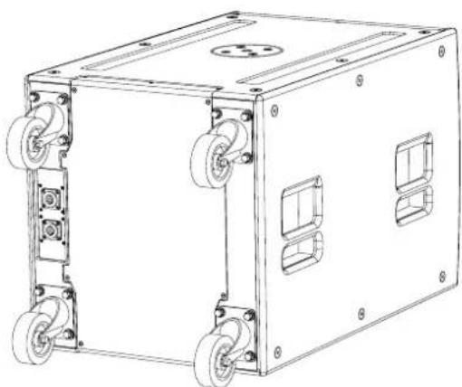
natural_image
Technical line drawing of a rectangular industrial or mechanical unit with multiple wheels and mounting holes (no text or symbols)Flying SXC115
Accessories
- 4 x HTKCT06
• Additional HTKCT06 M10 eyebolts can be used to implement a secondary safety
Eyebolts
The SXC115 features M10 inserts to allow flown applications using eyebolts. M10 eyebolts suitable for flown systems are available as accessories from Martin Audio.
Remove the M10 counter-sunk screws and screw the eyebolts into position. We would recommend four eyebolts and an additional eyebolt as a redundant safety bond. This should be attached to a different point than the other bolts to support the cabinet in the event of the other points failing.
ATTENTION! - Only 1 x SXC115 can be suspended using this method
natural_image
Line drawing of a rectangular industrial enclosure with mounting holes and internal compartments (no text or symbols)
natural_image
Line drawing of a rectangular industrial box with mounting holes and internal compartments (no text or symbols)Eyebolts should be connected to a suitably rated fixing point such as a girder clamp or a heavy duty fixing such as a sleeve anchor or similar. They can be linked using suitably rated steel rope or chain and shackles.
Safety note: Flying heavy equipment in public spaces is dangerous and should only be undertaken by suitably qualified and experienced personnel using adequately rated equipment for the task
INSTALLATION FLYING FRAME FOR SXC115
For permanent flown SXC115 array applications, the following accessories are needed. A maximum of X SXC115 enclosures can be flown using this method.
Accessories
- SXC115GRIDI
- FKIT550
natural_image
Line drawing of a three-tiered industrial enclosure unit with mounting holes and internal compartments (no text or symbols)1 x FKIT550 is required for each cabinet flown. The FKIT550 consists of
Accessories
- 4 x FK550
- 8 x M10 BTN SKT
- 8 x M10 Washer
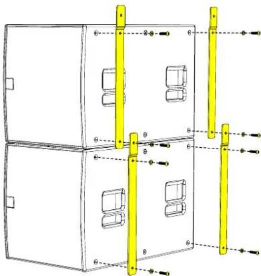
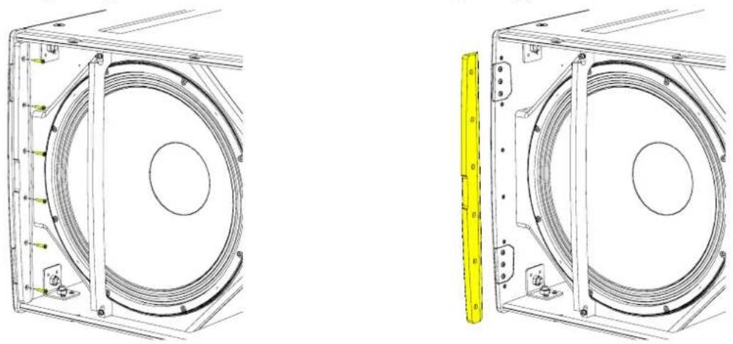
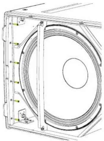
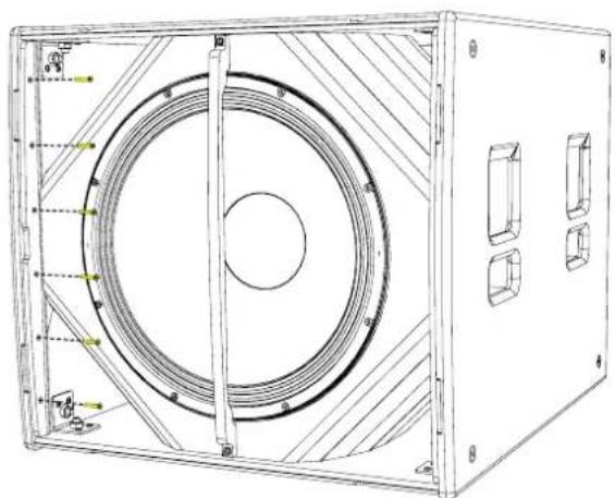
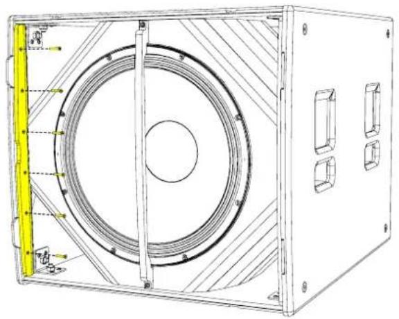
Remove all four M10 bolts in the inserts on the sides of the cabinet. These should be discarded and not used to secure the flying strips in place

natural_image
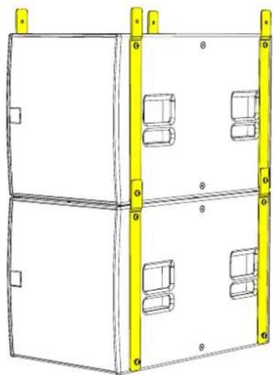
Technical line drawing of a two-tiered industrial enclosure with internal compartments and mounting holes (no text or symbols)Attach the FK550's (two on side) using the M10 bolts and washers provided.
natural_image
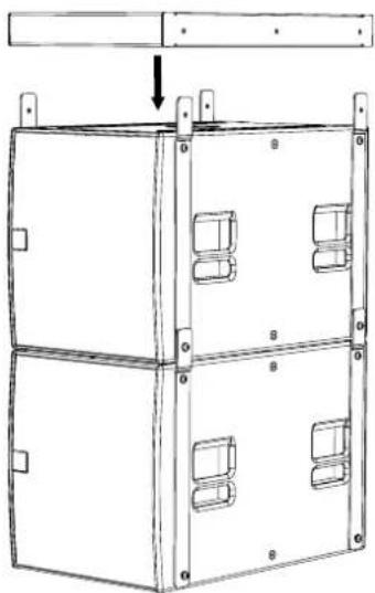
Technical line drawing of a two-tiered industrial cabinet with yellow vertical supports and mounting holes (no text or symbols)Position the SXC115GRIDI on top of the first SXCF115 subwoofer
natural_image
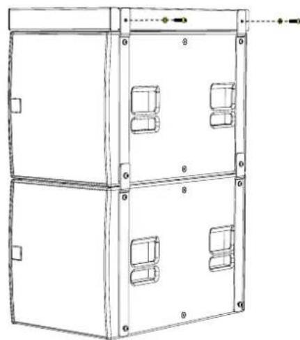
Technical line drawing of a two-tiered industrial enclosure with yellow frame and mounting holes (no text or symbols)Align to the FK550 holes and insert the rigging pins. Make sure the cabinet is secured on both sides before lifting.
natural_image
Technical line drawing of a multi-tiered industrial enclosure with mounting brackets and internal compartments (no text or symbols)Repeat the process for the desired number of cabinets for the array.
natural_image
Technical line drawing of a multi-level cabinet or enclosure with four vent slots and mounting holes (no text or symbols)Safety note: Flying heavy equipment in public spaces is dangerous and should only be undertaken by suitably qualified and experienced personnel using adequately rated equipment for the task
Specifications
TYPE Compact, cardioid subwoofer
FREQUENCY RESPONSE (1) 44Hz-150Hz ± 3dB, -10dB @ 36Hz
DRIVER 1 x 15" (380mm)/4" (100mm) voice coil, long excursion, ferrite magnet, waterproof cone
1 x 12" (300mm)/4" (88mm) voice coil, long excursion, neodymium magnet, waterproof
cone
RATED POWER (2) 15": 1000W AES, 4000W peak. 12": 800W AES, 3200W peak
RECOMMENDED AMPLIFIER IKON iK42
SENSITIVITY (10) 101dB
MAXIMUM SPL (9) 137dB continuous
NOMINAL IMPEDANCE 15": 8 ohms, 12": 8 ohms
DISPERSION Cardioid
ENCLOSURE Multi-laminate birch/poplar plywood
FINISH Textured black paint
PROTECTIVE GRILLE Black HEX perforated steel
CONNECTORS 2 x NL4
PIN CONNECTIONS (INPUT) 15" +1, -1 12": +2, -2
PIN CONNECTIONS (LINK) 15" +1, -1 12": +2, -2
FITTINGS Two skids on base, matching channels on top. 2 x bar handles.
M20 top-mounted thread plate for pole mounting
16 x M10 mounting points, 16 x M8 Inserts for optional castors
DIMENSIONS (INCL SKIDS) (W) 500mm x (H) 550mm x (D) 811mm (939mm including castors)
(W) 19.69in x (H) 21.67in x (D) 31.92in (96.96in including castors)
WEIGHT 53kg (117lbs). 56kg (124lbs) including castors
Notes
(1) Measured on-axis in half (2pi) space at 2 metres, then referred to 1 metre.
(2) AES Standard ANSI S4.26-1984.
(3) Measured in half (2pi) space at 2 metres with 1 watt input, using band limited pink noise, then referred to 1 metre.
(4) Measured in half (2pi) space at 2 metres using band limited pink noise, then referred to 1 metre.
(5) Measured on-axis in open (4pi) space at 2 metres, then referred to 1 metre.
(6) Measured in open (4pi) space at 2 metres with 1 watt input, using band limited pink noise, then referred to 1 metre.
(7) Measured in open (4pi) space at 2 metres using band limited pink noise, then referred to 1 metre.
(8) Measured in open (4pi) space at 2 metres with 2.83V input, using band limited pink noise, then referred to 1 metre.
(9) Calculated at 1 metre.
(10) Measured in half (2pi) space at 2 metres with 2.83V input, using band limited pink noise, then referred to 1 metre.
Technical Drawing

natural_image
Technical line drawing of a rectangular enclosure with a central circular component and two protruding legs (no text or symbols)
natural_image
Technical line drawing of a rectangular electronic enclosure with mounting holes and internal compartments (no text or symbols)
natural_image
Pure technical diagram of a rectangular device with two internal components and mounting holes (no text or symbols)
natural_image
Technical drawing of a rectangular enclosure with two internal compartments and mounting holes (no text or symbols)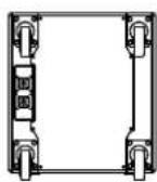
natural_image
Technical line drawing of a rectangular frame with two vertical supports and four wheels (no text or symbols)Castors are shown for illustration only and are not included as standard.
SX118

natural_image
Black rectangular electronic device with hexagonal perforated panel and 'M' logo on front (no readable text or symbols beyond branding)Introduction
The SX118 is a compact, high performance subwoofer that extends the low frequency operating range of the system to 47Hz and provides exceptional low frequency output for such a compact enclosure.
SX118 features a long-excursion 18" (460mm)/4" (100 mm) voice coil driver with a water-resistant cone and triple roll surround in a compact reflex enclosure.
The design of the 18" driver maximises output while minimising power compression and distortion, and the four reflex ports have a large frontal area to reduce turbulent air noise at very high levels. The enclosure is constructed from multi-laminate birch ply, finished with a durable polyurea coating and equipped with a Zintec grille, twin grab handles, skids, flying inserts for installation and a threaded pole socket for pole-mounting point source loudspeakers or up to 4 WPM enclosures as a simple plug-and-play system.
The product is supplied as standard without cabinet wheels, but they are available as an accessory.
By adding the input board cover accessory, SX118 is fully weather resistant and suitable for permanent outdoor usage.
Accessories
M10 eyebolts HTKCT06
Transit cover SXTC118
Castor kit WHEELKIT
Wind-up pole ASF20071
Weather kit WRKIT
Connections
text_image
SX SERIES INPUT 1+, 1- 2+, 2- LINK THRU LINK 1+, 1- 2+, 2- LINK THRU MODE IN ENGLAND BY MARTIN AUDIO LIMITED CREATURE POINT MULICO ROAD, CENSILEE BUSINESS PRICE, HIGH MTCOME, SUCF, SPD: 35. TEL: +RUBISH DRUST 2 PAE +RAKTER SERIES www.martin-audio.com Serial No. FOR FURTHER INFORMATION CONSULT THE PRODUCT MANUALThe SX118 has a pair of NL4 connectors on the rear panel. These are wired in parallel and whilst one is nominally labelled 'INPUT' and the other as 'LINK', connection in and out can be made to either connector. Connection to the drive unit(s) is made to pins 1+/-. There is no internal connection to pins 2+/- although these are linked together so can be used for example to carry a mid/top signal and connected to a full range system using a cable wired with reverse connections (pins 2 to pins 1).
Flying SX118
Eyebolts
The SX118 features M10 inserts to allow flown applications using eyebolts. M10 eyebolts suitable for flown systems are available as accessories from Martin Audio. These are cast steel shouldered eye bolts specifically designed and rated for flown applications. If alternative eyebolts are used these must be cast or machined products stamped with their SWL. Formed steel non-shouldered eyebolts commonly available from DIY stores should not be used under any circumstances as they are not sufficiently load-rated for flown applications.
natural_image
Line drawing of a rectangular industrial enclosure with mounting holes and internal compartments (no text or symbols)Remove the M10 counter-sunk screws and screw the eyebolts into position. We would recommend four eyebolts and an additional eyebolt as a redundant safety bond. This should be attached to a different point than the other bolts to support the cabinet in the event of the other points failing.
Eyebolts should be connected to a suitably rated fixing point such as a girder clamp or a heavy duty fixing such as a sleeve anchor or similar. They can be linked using suitably rated steel rope or chain and shackles.
Safety note: Flying heavy equipment in public spaces is dangerous and should only be undertaken by suitably qualified and experienced personnel using adequately rated equipment for the task.
Transit Covers
The SX118 features an optional transit cover to protect the cabinet when used in portable applications.
To ensure that the insert is accurately located, four locating brackets are utilised. These are built into the cabinet in the four corners and maybe fitted in the parked position as standard. To use with the transit cover it is necessary to reverse the four brackets.
Remove the top and bottom safety screws from the grille. Insert a flat blade screwdriver into the slots of the grille and carefully easing the grille out of the slot.

natural_image
Technical line drawings of two mechanical components with no visible text or symbolsRemove the screws from the grille support on the side of the cabinet and remove the grille support.
natural_image
Technical line drawings of two mechanical components with circular cutouts and mounting brackets (no text or symbols)Remove the three screws from the bracket.

natural_image
Technical line drawing of a mechanical assembly with no visible text or symbolsRotate the bracket 180°. The bracket will now extend approximately 20mm from the front edge of the cabinet, ensure that the slope on the bracket follows the curved contour of the cabinet.

natural_image
Technical line drawing of a mechanical bracket with a yellow component and curved internal structure (no text or symbols)Screw the bracket back in place and repeat for the other three brackets.

natural_image
Technical line drawing of a mechanical bracket with attached wiring and mounting holes (no text or symbols)
natural_image
Technical line drawing of a mechanical bracket with a yellow safety clip attached (no text or symbols)Replace the grill supports and fit the grille making sure the safety screws are replaced.
natural_image
Technical line drawing of a mechanical component with concentric circular and rectangular features (no text or symbols)
natural_image
Simple line drawing of a door frame with yellow connectors and a small square opening (no text or symbols)Castors
To fit the castors, remove the M8 counter-sunk screws from the rear of the enclosure.

natural_image
Technical line drawing of a rectangular electronic device with mounting holes and internal compartments (no text or symbols)Position each castor over the insets and screw into place using the fixings supplied in the kit.
natural_image
Technical line drawing of a mechanical device with mounting holes and internal components (no text or symbols)Weather Kit
The WRKIT for non-powered SX Series subwoofers is a glanded cover which fits over the connection panel to prevent water ingress protecting the NL4 speaker connection.
The cable entry may be through one of two knock-out positions depending the angle from which you wish the cable to enter. First remove the knock-out blank that you wish to use and fit the cable gland in position. Note that to use the WRKIT it is necessary to remove the NL4 connector from your speaker cable so the cable can be fed through the cable gland. Once the cable has been threaded through the gland the NL4 can be re-attached.
Remove the four counter-sunk screws in the connector panel and position the cover on the connector panel. Connect the NL4 to the input connector and position the cover, pulling the slack in the speaker cable as you lower the cover in position. Secure the cover using the four M4 x 25 cap socket screws and fibre washers. Finally tighten the gland to ensure a waterproof seal.

natural_image
Technical line drawing of a mechanical enclosure with mounting holes and internal components (no text or symbols)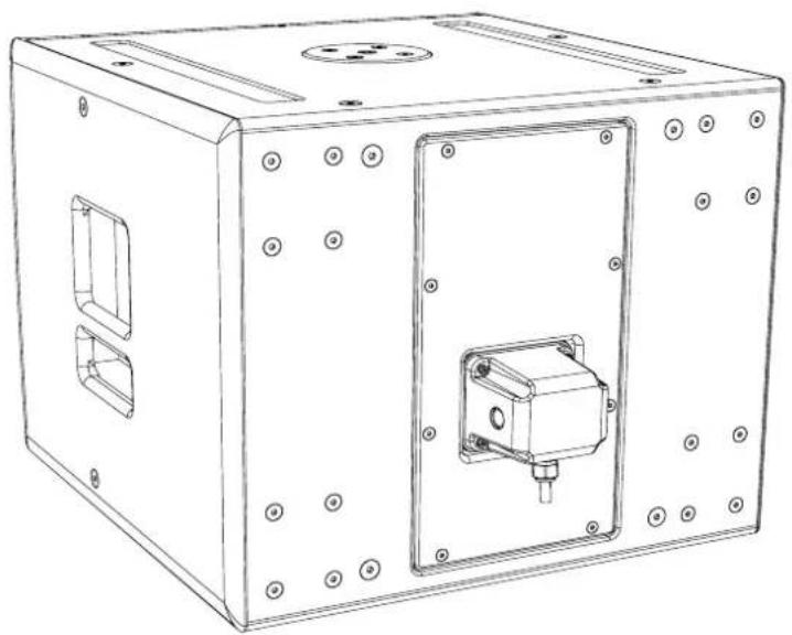
natural_image
Technical line drawing of a rectangular electronic device with mounting holes and internal components (no text or symbols)Specifications
| TYPE Compact, direct radiating subwoofer | |
| FREQUENCY RESPONSE (1) 47Hz-150Hz ± 3dB, -10dB @ 41Hz | |
| DRIVER 1 x 18" (460mm)/4" (100mm) voice coil, long excursion, ferrite magnet, waterproof cone | |
| RATED POWER (2) 1000W AES, 4000W peak | |
| RECOMMENDED AMPLIFIER iK42/81 | |
| SENSITIVITY (10) 102dB | |
| MAXIMUM SPL (9) 138dB continuous | |
| NOMINAL IMPEDANCE 8 ohms | |
| DISPERSION (-6dB) Omnidirectional | |
| CROSSOVER 80-120Hz active | |
| ENCLOSURE Multi-laminate birch/poplar plywood | |
| FINISH Textured black paint | |
| PROTECTIVE GRILLE Perforated steel | |
| CONNECTORS 2 x NL4 | |
| PIN CONNECTIONS (INPUT) +1, -1 (+2, -2 link through) | |
| PIN CONNECTIONS (LINK) +1, -1 (+2, -2 link through) | |
| FITTINGS | Two skids on base, with mating channels on top |
| Four rear-mounted 100mm (4in) castors | |
| M20 top-mounted thread plate for pole mounting | |
| 16 x M10 mounting points | |
| 2 x bar handles, 1 on each side | |
| 4 x fittings for optional transit cover | |
| DIMENSIONS (INCL FEET) | (W) 600mm x (H) 509mm x (D) 632mm (760mm including castors) |
| (W) 23.62in x (H) 20.04in x (D) 24.86in (29.9in including castors) | |
| WEIGHT | 47kg (104lbs) |
Technical Drawing
Notes
(1) Measured on-axis in half (2pi) space at 2 metres, then referred to 1 metre.
(2) AES Standard ANSI S4.26-1984.
(3) Measured in half (2pi) space at 2 metres with 1 watt input, using band limited pink noise, then referred to 1 metre.
(4) Measured in half (2pi) space at 2 metres using band limited pink noise, then referred to 1 metre.
(5) Measured on-axis in open (4pi) space at 2 metres, then referred to 1 metre.
(6) Measured in open (4pi) space at 2 metres with 1 watt input, using band limited pink noise, then referred to 1 metre.
(7) Measured in open (4pi) space at 2 metres using band limited pink noise, then referred to 1 metre.
(8) Measured in open (4pi) space at 2 metres with 2.83V input, using band limited pink noise, then referred to 1 metre.
(9) Calculated at 1 metre.
(10) Measured in half (2pi) space at 2 metres with 2.83V input, using band limited pink noise, then referred to 1 metre.

natural_image
Technical line drawing of a rectangular enclosure with internal components and dimension lines (no text or symbols)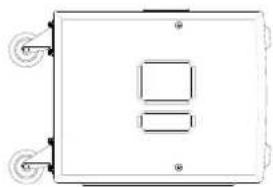
natural_image
Simple line drawing of a rectangular box with two internal square cutouts and four wheels on both sides (no text or symbols)
natural_image
Technical drawing of a circular mechanical component with mounting holes and a central hole, shown without any text or symbols.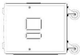
natural_image
Simple line drawing of a rectangular box with two side handles and a central square cutout (no text or symbols)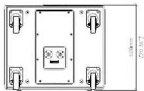
natural_image
Pure technical diagram of a rectangular enclosure with mounting holes and internal components (no text or symbols)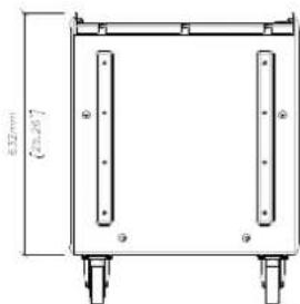
text_image
0.52 mm (20.20°)Castors are shown for illustration only and are not included as standard.
SXC118

natural_image
Two black server units with ventilation grilles, one emitting heat and the other emitting exhaust (no visible text or symbols)Introduction
Designed for touring sound and installations, the SXC118 is a compact, high performance cardioid subwoofer. It features an 18" (460mm) forward facing driver and a 14" (356mm) rear facing driver, each driven independently by separate amplifier channels and DSP. Each driver has its own chamber with optimised bass reflex porting.
This arrangement produces a cardioid dispersion pattern which maximises the front radiation and reduces unwanted radiation behind the subwoofer.
The recommended iK42 amplifier optimises the DSP parameters for front and rear drivers to maximise the rear rejection — from 21dB at 43Hz to 28dB at 75Hz. This keeps low frequencies away from stages, turntables and walls as well as reducing reverberant energy in the room, greatly improving the system's low frequency response accuracy and impact.
In front of the enclosure, the output from the two drivers is additive, giving an extra 2dB of output when compared with a conventional 1 x 18" subwoofer.
Accessories
M10 eyebolts HTKCT06
Transit cover SXC118TC
Castor kit WHEELKIT
Wind-up pole ASF20071
Weather kit WRKIT
Connections
text_image
SX SERIES MADE IN ENGLAND BY MARTIN AUDIO LTD INPUT LINK FOR FURTHER INFORMATION REFER TO PRODUCT USER GUIDEThe SXC118 features two drivers, an 18" front facing driver and the rear-facing 14" driver used to achieve a cardioid response. Connection is made via two NL4 connectors which are wired in parallel. Although these are nominally labelled 'INPUT' and 'LINK', either connector can be used to connect to the sub or to link out to a second speaker. The Front 18" driver is connected to pins 1+/-, the rear 14" driver to pins 2+/-. A 4-core NL4 cable must be used. If using the recommended iK42 amplifier, connection can be made to output NL4 1 or 3 as these also carry the output signal from channels 2 and 4 respectively to power both drivers.
Flying SXC118
Eyebolts
The SXC118 features M10 inserts to allow flown applications using eyebolts. M10 eyebolts suitable for flown systems are available as accessories from Martin Audio. These are cast steel shouldered eye bolts specifically designed and rated for flown applications. If alternative eyebolts are used these must be cast or machined products stamped with their SWL. Formed steel non-shouldered eyebolts commonly available from DIY stores should not be used under any circumstances as they are not sufficiently load-rated for flown applications.

natural_image
Line drawing of a rectangular industrial enclosure with mounting holes and internal compartments (no text or symbols)Remove the M10 counter-sunk screws and screw the eyebolts into position. We would recommend four eyebolts and an additional eyebolt as a redundant safety bond. This should be attached to a different point than the other bolts to support the cabinet in the event of the other points failing.
Eyebolts should be connected to a suitably rated fixing point such as a girder clamp or a heavy duty fixing such as a sleeve anchor or similar. They can be linked using suitably rated steel rope or chain and shackles.
Safety note: Flying heavy equipment in public spaces is dangerous and should only be undertaken by suitably qualified and experienced personnel using adequately rated equipment for the task.
Transit Covers
The SXC118 features an optional transit cover to protect the cabinet when used in portable applications.
To ensure that the insert is accurately located, four locating brackets are utilised. These are built into the cabinet in the four corners and maybe fitted in the parked position as standard. To use with the transit cover it is necessary to reverse the four brackets.
Remove the top and bottom safety screws from the grille. Insert a flat blade screwdriver into the slots of the grille and carefully easing the grille out of the slot.
natural_image
Line drawing of a rectangular electronic device with a close-up inset showing internal components (no text or symbols)
natural_image
Line drawing of a rectangular electronic device with a small square component and a thermometer on top (no text or symbols)Remove the screws from the grille support on the side of the cabinet and remove the grille support.
natural_image
Technical line drawing of a mechanical enclosure with circular components and mounting holes (no text or symbols)
natural_image
Technical line drawing of a mechanical enclosure with circular components and mounting brackets (no text or symbols)Remove the three screws from the bracket.

natural_image
Technical line drawing of a mechanical enclosure with circular components and mounting brackets (no text or symbols)Rotate the bracket 180°. The bracket will now extend approximately 20mm from the front edge of the cabinet, ensure that the slope on the bracket follows the curved contour of the cabinet.

natural_image
Technical line drawing of a mechanical enclosure with circular speaker and mounting holes (no text or symbols)Screw the bracket back in place and repeat for the other three brackets.

natural_image
Technical line drawing of a mechanical enclosure with circular components and mounting brackets (no text or symbols)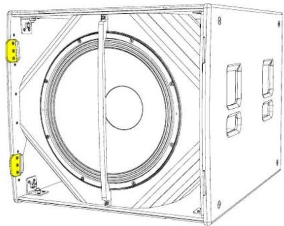
natural_image
Technical line drawing of a mechanical enclosure with circular components and mounting brackets (no text or symbols)Replace the grill supports and fit the grille making sure the safety screws are replaced.
natural_image
Technical line drawing of a mechanical enclosure with circular components and mounting brackets (no text or symbols)
natural_image
Line drawing of a rectangular electronic enclosure with mounting holes and internal compartments (no text or symbols)Castors
To fit the castors, remove the M8 counter-sunk screws from the rear of the enclosure.
natural_image
Technical line drawing of a rectangular electronic device with mounting holes and internal components (no text or symbols)Position each castor over the insets and screw into place using the fixings supplied in the kit.
natural_image
Technical line drawing of a mechanical device with mounting holes and a central circular component (no text or symbols)Weather Kit
The WRKIT for non-powered SX Series subwoofers is a glanded cover which fits over the connection panel to prevent water ingress protecting the NL4 speaker connection.
The cable entry may be through one of two knock-out positions depending the angle from which you wish the cable to enter. First remove the knock-out blank that you wish to use and fit the cable gland in position. Note that to use the WRKIT it is necessary to remove the NL4 connector from your speaker cable so the cable can be fed through the cable gland. Once the cable has been threaded through the gland the NL4 can be re-attached.
Remove the four counter-sunk screws in the connector panel and position the cover on the connector panel. Connect the NL4 to the input connector and position the cover, pulling the slack in the speaker cable as you lower the cover in position. Secure the cover using the four M4 x 25 cap socket screws and fibre washers. Finally tighten the gland to ensure a waterproof seal.
natural_image
Technical line drawings of a two-port electrical enclosure with internal components and mounting holes (no text or symbols)Specifications
TYPE Compact, cardioid subwoofer
FREQUENCY RESPONSE (1) 43Hz-150Hz ± 3dB, -10dB @ 34Hz
DRIVER 1 x 18" (460mm)/4" (100mm) voice coil, long excursion, ferrite magnet, waterproof cone
1 x 14" (365mm)/3.5" (88mm) voice coil, long excursion, neodymium magnet, waterproof
RATED POWER (2) 18": 1000W AES, 4000W peak. 14": 800W AES, 3200W peak
RECOMMENDED AMPLIFIER iK42
SENSITIVITY (10) 104dB
MAXIMUM SPL (9) 140dB continuous
NOMINAL IMPEDANCE 18": 8 ohms, 14": 8 ohms
DISPERSION (-6dB) Cardioid
CROSSOVER 80-120Hz active
ENCLOSURE Multi-laminate birch/poplar plywood
FINISH Textured black paint
PROTECTIVE GRILLE Perforated steel
CONNECTORS 2 x NL4
PIN CONNECTIONS (INPUT) 18" +1, -1 14": +2, -2
PIN CONNECTIONS (LINK) 18" +1, -1 14": +2, -2
FITTINGS Two skids on base, with mating channels on top
M20 top-mounted thread plate for pole mounting
Two bar handles on each side
Four fittings for optional transit cover
16 x M10 mounting points
16 x M8 inserts for optional castors
DIMENSIONS (INCL FEET) (W) 650mm x (H) 603mm x (D) 812mm (940mm incl castors)
(W) 25.6in x (H) 23.7in x (D) 32in (37in incl castors)
WEIGHT 69kg (152lbs). 73kg (161lbs) including castors
73kg (161lbs) incl castors
Notes
(1) Measured on-axis in half (2pi) space at 2 metres, then referred to 1 metre.
(2) AES Standard ANSI S4.26-1984.
(3) Measured in half (2pi) space at 2 metres with 1 watt input, using band limited pink noise, then referred to 1 metre.
(4) Measured in half (2pi) space at 2 metres using band limited pink noise, then referred to 1 metre.
(5) Measured on-axis in open (4pi) space at 2 metres, then referred to 1 metre.
(6) Measured in open (4pi) space at 2 metres with 1 watt input, using band limited pink noise, then referred to 1 metre.
(7) Measured in open (4pi) space at 2 metres using band limited pink noise, then referred to 1 metre.
(8) Measured in open (4pi) space at 2 metres with 2.83V input, using band limited pink noise, then referred to 1 metre.
(9) Calculated at 1 metre.
(10) Measured in half (2pi) space at 2 metres with 2.83V input, using band limited pink noise, then referred to 1 metre.
Technical Drawing
natural_image
Technical line drawing of a rectangular enclosure with a central circular component and two protruding posts (no text or symbols)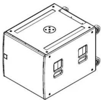
natural_image
Line drawing of a 3D box with internal compartments and mounting holes (no text or symbols)
natural_image
Technical diagram of a rectangular enclosure with two square cutouts and three wheels (no text or symbols)
text_image
650.00mm [25,59°]
natural_image
Technical diagram of a rectangular enclosure with two internal square cutouts and mounting feet (no text or symbols)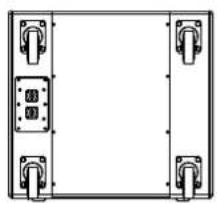
natural_image
Simple line drawing of a rectangular frame with four corner clips and a central blank space (no text or symbols)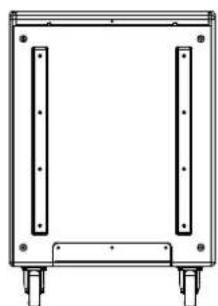
natural_image
Technical line drawing of a rectangular frame with two vertical supports and two wheels at the bottom (no text or symbols)Castors are shown for illustration only and are not included as standard.
SXCF118

natural_image
Two black industrial server units with blue scroll handles and ventilation grilles, no visible text or symbols on the devices themselves.Introduction
The SXCF118 is a compact, high performance cardioid subwoofer. The flown version of the SXC118, it is the ideal partner for flown WPS arrays — combining maximum low frequency output with pattern control. It features an 18" (460mm) forward facing driver and a 14" (356mm) rear facing driver, each driven independently by separate amplifier channels and DSP. Each driver has its own chamber with optimised bass reflex porting.
This arrangement produces a cardioid dispersion pattern which maximises the front radiation and reduces unwanted radiation behind the subwoofer.
The recommended iK42 amplifier optimises the DSP parameters for front and rear drivers to maximise the rear rejection — from 21dB at 43Hz to 28dB at 75Hz. This keeps low frequencies away from stages, turntables and walls as well as reducing reverberant energy in the room, greatly improving the system's low frequency response accuracy and impact.
In front of the enclosure, the output from the two drivers is additive, giving an extra 2dB of output when compared with a conventional 1 x 18" subwoofer.
Accessories
M10 eyebolts HTKCT06
Transit cover SXC118TC
Castor kit WHEELKIT
Wind-up pole ASF20071
Weather kit WRKIT
Flying frame WPSGRIDt
Connections
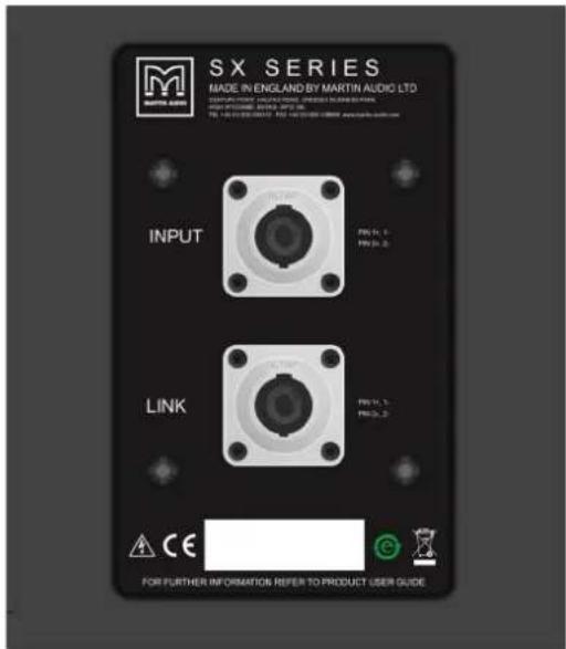
text_image
SX SERIES MADE IN ENGLAND BY MARTIN AUDIO LTD INPUT LINK FOR FURTHER INFORMATION REFER TO PRODUCT USER GUIDEThe SXCF118 features two drivers, an 18" front facing driver and the rear-facing 14" driver used to achieve a cardioid response. Connection is made via two NL4 connectors which are wired in parallel. Although these are nominally labelled 'INPUT' and 'LINK', either connector can be used to connect to the sub or to link out to a second speaker. The Front 18" driver is connected to pins 1+/-, the rear 14" driver to pins 2+/-. A 4-core NL4 cable must be used. If using the recommended iK42 amplifier, connection can be made to output NL4 1 or 3 as these also carry the output signal from channels 2 and 4 respectively to power both drivers.
Flying SXCF118
Eyebolts
The SXC118 features M10 inserts to allow flown applications using eyebolts. M10 eyebolts suitable for flown systems are available as accessories from Martin Audio. These are cast steel shouldered eye bolts specifically designed and rated for flown applications. If alternative eyebolts are used these must be cast or machined products stamped with their SWL. Formed steel non-shouldered eyebolts commonly available from DIY stores should not be used under any circumstances as they are not sufficiently load-rated for flown applications.

natural_image
Line drawing of a rectangular industrial or laboratory enclosure with mounting holes and internal compartments (no text or symbols)Remove the M10 counter-sunk screws and screw the eyebolts into position. We would recommend four eyebolts and an additional eyebolt as a redundant safety bond. This should be attached to a different point than the other bolts to support the cabinet in the event of the other points failing.
Eyebolts should be connected to a suitably rated fixing point such as a girder clamp or a heavy duty fixing such as a sleeve anchor or similar. They can be linked using suitably rated steel rope or chain and shackles.
Safety note: Flying heavy equipment in public spaces is dangerous and should only be undertaken by suitably qualified and experienced personnel using adequately rated equipment for the task.
WPSGRIDt
Using one or two motors position a WPSGRIDt above the SCXF118 and lower it onto the enclosure.

natural_image
Line drawing of a rectangular device with hanging chains and mounting brackets (no text or symbols)Replace the pins to link and lock the SXCF118 securely to the WPSGRIDt.
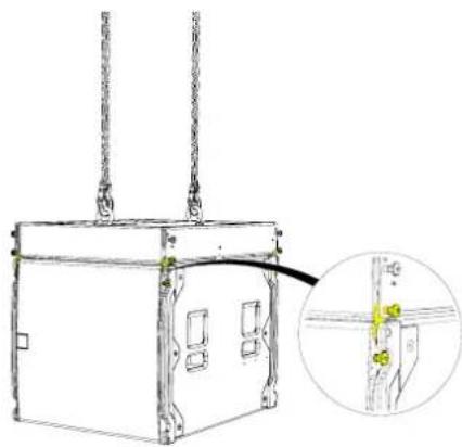
natural_image
Technical line drawing of a mechanical device with hanging chains and a close-up inset showing a small component detail (no text or symbols)Remove the pins from the stow position, rotate the links to line up with the pin hole position on the SXCF118 above.

natural_image
Technical line drawing of a rectangular mechanical or electrical enclosure with mounting brackets and internal compartments, showing a close-up inset of a cable or wire connection (no text or symbols present)Remove the pins from the from SXCF118 to release the links. Rotate the SXCF118 links and line them up with the pin holes in the WPSGRIDt.

natural_image
Technical line drawing of a mechanical device with hanging rods and a close-up inset showing a cable or wire connection (no text or symbols)Raise the WPSGRIDt and SXCF118 to a height suitable to fit another SXCF118 below the array, lower it making sure the protective nylon skids line up and fit into the recessed channels on the SXCF118 below.

natural_image
Diagram of a mechanical device with two boxes and a downward arrow indicating transformation (no text or symbols)Replace the pins into the lock position on the cabinet above making sure all four links are securely attached.
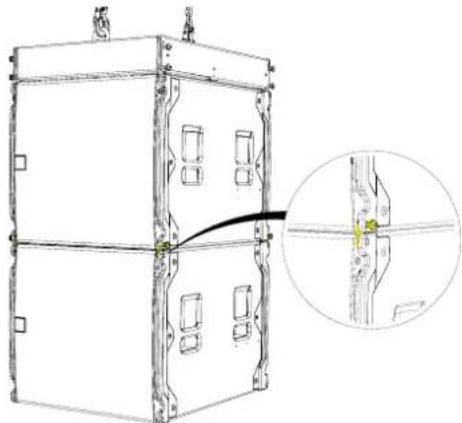
natural_image
Technical line drawing of a multi-compartment electronic device with mounting brackets and a close-up inset showing a cable or wire connection (no text or symbols)Repeat the procedure for each sub to be included in the array to a maximum of 16 SXCF118. For arrays that consist of SXCF118 and WPS, please refer to the WPS manual.
Transit Covers
The SXC118 features an optional transit cover to protect the cabinet when used in portable applications.
Castors
To fit the castors, remove the M8 counter-sunk screws from the rear of the enclosure.

natural_image
Technical line drawing of a computer case chassis with mounting holes and internal components (no text or symbols)Position each castor over the insets and screw into place using the fixings supplied in the kit.

natural_image
Technical line drawing of a mechanical device with mounting holes and a coiled spring (no text or symbols)Weather Kit
The WRKIT for non-powered SX Series subwoofers is a glanded cover which fits over the connection panel to prevent water ingress protecting the NL4 speaker connection.
The cable entry may be through one of two knock-out positions depending the angle from which you wish the cable to enter. First remove the knock-out blank that you wish to use and fit the cable gland in position. Note that to use the WRKIT it is necessary to remove the NL4 connector from your speaker cable so the cable can be fed through the cable gland. Once the cable has been threaded through the gland the NL4 can be re-attached.
Remove the four counter-sunk screws in the connector panel and position the cover on the connector panel. Connect the NL4 to the input connector and position the cover, pulling the slack in the speaker cable as you lower the cover in position. Secure the cover using the four M4 x 25 cap socket screws and fibre washers. Finally tighten the gland to ensure a waterproof seal.
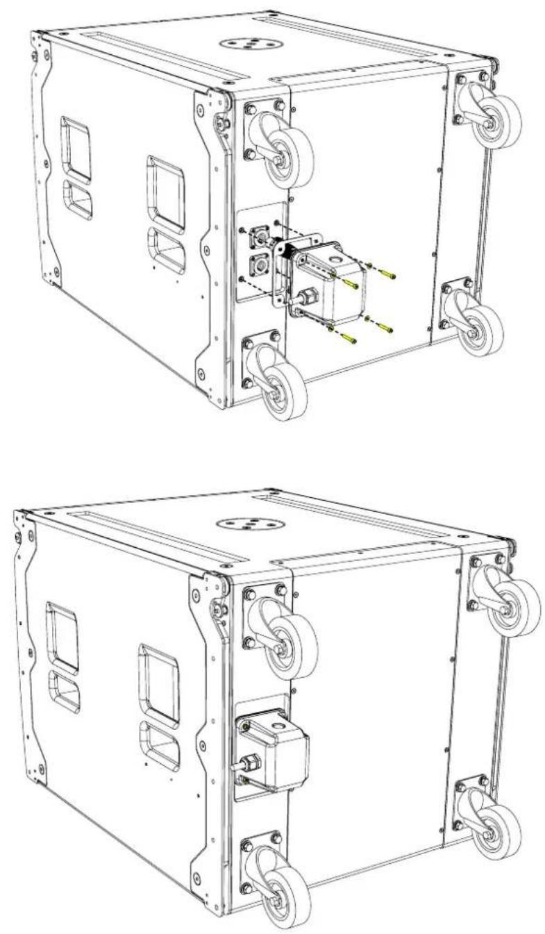
Specifications
TYPE Compact, cardioid subwoofer
FREQUENCY RESPONSE (1) 43Hz-150Hz ± 3dB, -10dB @ 34Hz
DRIVER 1 x 18" (460mm)/4" (100mm) voice coil, long excursion, ferrite magnet, waterproof cone
1 x 14" (365mm)/3.5" (88mm) voice coil, long excursion, neodymium magnet, waterproof cone
RATED POWER (2) 18": 1000W AES, 4000W peak. 14": 800W AES, 3200W peak
RECOMMENDED AMPLIFIER IKON iK42
SENSITIVITY (10) 104dB
MAXIMUM SPL (9) 140dB continuous
NOMINAL IMPEDANCE 18": 8 ohms, 14": 8 ohms
DISPERSION Cardioid
ENCLOSURE Multi-laminate birch/poplar plywood
FINISH Textured black paint
PROTECTIVE GRILLE Black HEX perforated steel
CONNECTORS 2 x NL4
PIN CONNECTIONS (INPUT) 18" +1, -1 14": +2, -2
PIN CONNECTIONS (LINK) 18" +1, -1 14": +2, -2
FITTINGS Two skids on base, matching channels on top. 2 x bar handles.
M20 top-mounted thread plate for pole mounting
16 x M10 mounting points, 4 x fittings for optional transit cover
DIMENSIONS (INCL SKIDS) (W) 650mm x (H) 611mm x (D) 812mm (940mm including castors)
(W) 25.6in x (H) 24.1in x (D) 32.0in (37.0in including castors)
WEIGHT 75kg (165lbs). 78kg (172lbs) including castors
Notes
(1) Measured on-axis in half (2pi) space at 2 metres, then referred to 1 metre.
(2) AES Standard ANSI S4.26-1984.
(3) Measured in half (2pi) space at 2 metres with 1 watt input, using band limited pink noise, then referred to 1 metre.
(4) Measured in half (2pi) space at 2 metres using band limited pink noise, then referred to 1 metre.
(5) Measured on-axis in open (4pi) space at 2 metres, then referred to 1 metre.
(6) Measured in open (4pi) space at 2 metres with 1 watt input, using band limited pink noise, then referred to 1 metre.
(7) Measured in open (4pi) space at 2 metres using band limited pink noise, then referred to 1 metre.
(8) Measured in open (4pi) space at 2 metres with 2.83V input, using band limited pink noise, then referred to 1 metre.
(9) Calculated at 1 metre.
(10) Measured in half (2pi) space at 2 metres with 2.83V input, using band limited pink noise, then referred to 1 metre.
Technical Drawing
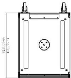
natural_image
Technical line drawing of a rectangular enclosure with internal components and a central circular feature (no text or symbols)
natural_image
Technical line drawing of a rectangular electronic enclosure with mounting holes and internal compartments (no text or symbols)
natural_image
Technical line drawing of a rectangular mechanical housing with mounting flanges and bolt holes (no text or symbols)
text_image
650.00mm [25,59]
text_image
940.00mm [37.0]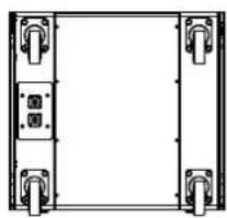
natural_image
Pure electrical circuit lines without any symbols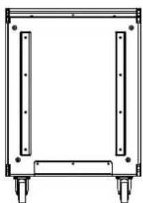
natural_image
Simple line drawing of a rectangular frame with four vertical supports and two wheels at the bottom (no text or symbols)Castors are shown for illustration only and are not included as standard.
SX218

natural_image
Exterior view of a black industrial electronic device with perforated panel and mounting bracket (no visible text or symbols)Introduction
The SX218 achieves the ultimate in subwoofer performance for the most demanding applications – delivering very high output levels and superb transient performance with minimal distortion.
With an operating range of 35Hz-150Hz ± 3dB, it houses dual 18" long excursion (460mm)/4" (100mm) voice coil drivers with water-resistant cones and triple roll surrounds. Each driver is rated to handle 1000 watts AES, and has a magnet structure and suspension engineered for maximum linear excursion.
The enclosure is constructed from multi-laminate birch ply and finished with a durable polyurea coating. Eight reflex ports provide a large frontal area to reduce turbulent air noise, and a perforated steel grille protects the drivers from damage.
The product is supplied as standard without cabinet wheels, but they are available as an accessory.
By adding the input board cover accessory, SX218 is fully weather resistant and suitable for permanent outdoor usage.
A flying system is available for installed systems which require a flown subwoofer solution.
Accessories
M10 eyebolts HTKCT06
Install flying frame SX218GRIDi
Flying kit SX218FKIT
Transit cover SXTC218
Castor kit WHEELKIT
Wind-up pole ASF20071
Weather kit WRKIT
Connections
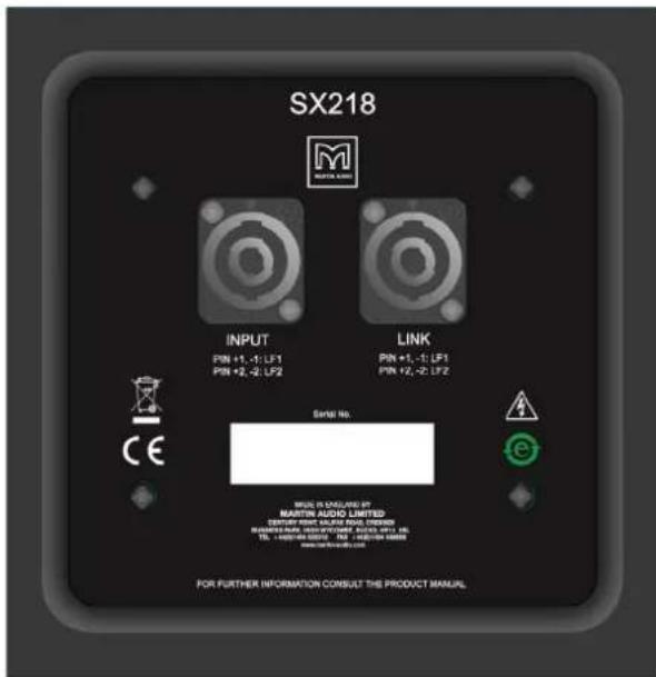
text_image
SX218 INPUT PIN +1, -1: LF1 PIN +2, -2: LF2 LINK PIN +1, -1: LP1 PIN +2, -2: LF2 SERIAL No. MARTIN AUDIO LIMITED CERTIFIED ORDER NO. 000-0000000000000000000000000000000000000000000000000000000000000000000000000000 FOR FURTHER INFORMATION CONSULT THE PRODUCT MANUALThe SX218 has independent wiring to each of the 18" drivers. This is done so that all four cores of a standard NL4 speaker cable are used to feed the sub, keeping losses through the cable to a minimum. LF driver 1 is connected to pins 1+/-, LF driver 2 is wired to pins 2+/-. The link connector is wired in parallel with the input connector. You can drive the SX218 from two amplifier channels, for example directly out of channel 1 or 3 from an iK42, if you then link the SX218 to a second sub, each amplifier channel will be seeing a 4Ω load. When driving the sub from a single amplifier channel you will need to use a patch panel that links the amplifier output to both pins 1+/- and pins 2+/- and make sure you use a 4-core NL4 cable to connect from your patch panel to the SX218.
Modifying the wiring
The SX218 input panel has a facility to allow quick and easy modification to link both drivers so the connection to pin 1+ is linked to 2+ and 1- to 2-. Please note that if this modification is done you must not use two channels to drive the SX218, you will effectively be shorting the amplifier channels together which is likely to cause damage.
To modify the sub, disconnect any speaker cables and carefully remove the panel on which the connector plate is mounted on the rear of the cabinet. There should be enough slack on the cables going to each driver but if not disconnect the cables from each driver making a note of the orientation of the wiring. Turn the panel over to expose the rear of the connector plate. At the top of the plate you will see two pairs of wiring tags. These have a brown, red, black and blue wires feeding them. To convert the wiring solder a short wire link from the brown to the red terminal and a second link from the black to the blue. Re-connect the drivers if these were disconnected ensuring that driver polarity is correct. Refit the panel into the cabinet. We would recommend labelling the connector panel to make it obvious that pins 1 & 2 are now linked.
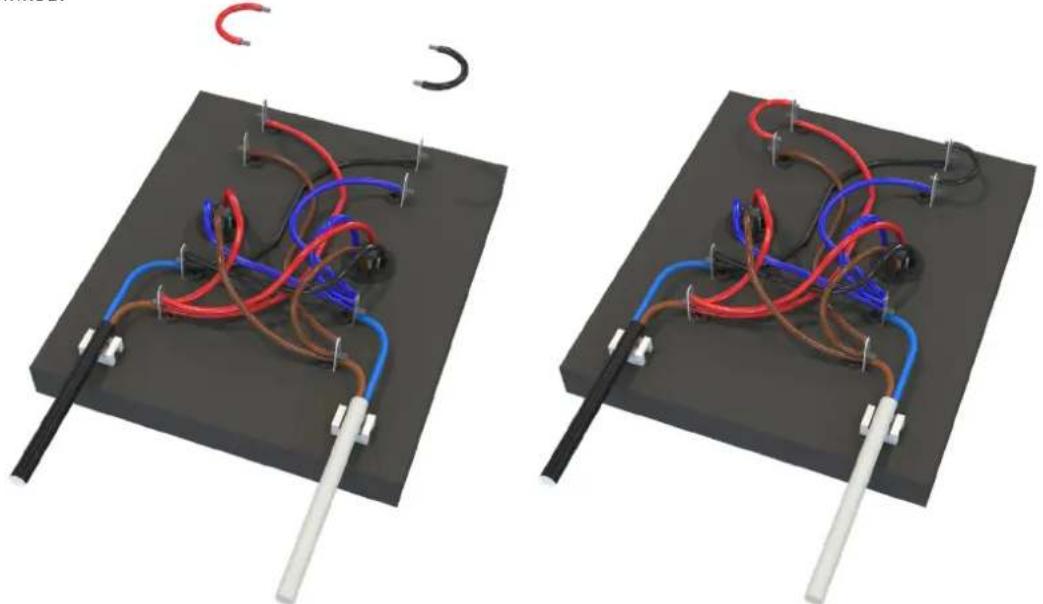
natural_image
Two identical 3D diagrams of a mechanical or electrical device with red, blue, and brown wires connected by rods, mounted on a black base with metal rods (no text or symbols visible)Flying SX218
Eyebolts
The SX218 features M10 inserts to allow flown applications using eyebolts. M10 eyebolts suitable for flown systems are available as accessories from Martin Audio. These are cast steel shouldered eye bolts specifically designed and rated for flown applications. If alternative eyebolts are used these must be cast or machined products stamped with their SWL. Formed steel non-shouldered eyebolts commonly available from DIY stores should not be used under any circumstances as they are not sufficiently load-rated for flown applications.
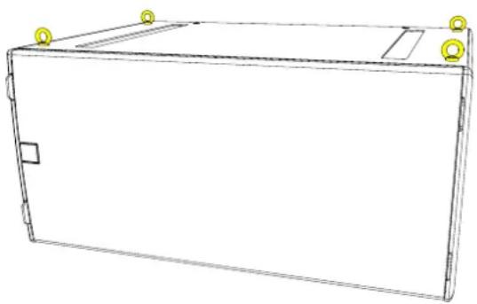
natural_image
Line drawing of a rectangular electronic device with mounting holes and a flat panel (no text or symbols)Remove the M10 counter-sunk screws and screw the eyebolts into position. We would recommend four eyebolts and an additional eyebolt as a redundant safety bond. This should be attached to a different point than the other bolts to support the cabinet in the event of the other points failing.
Eyebolts should be connected to a suitably rated fixing point such as a girder clamp or a heavy duty fixing such as a sleeve anchor or similar. They can be linked using suitably rated steel rope or chain and shackles.
Safety note: Flying heavy equipment in public spaces is dangerous and should only be undertaken by suitably qualified and experienced personnel using adequately rated equipment for the task.
Flying Frame and Flying Kit
A flying system is available for the SX218 for installation applications. This uses the SX218FKIT and SX218GRIDi.
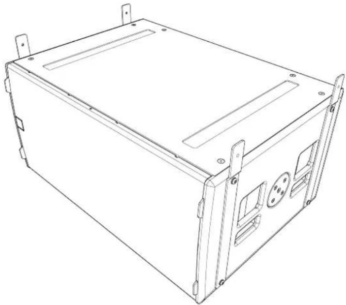
natural_image
Line drawing of a rectangular electronic device casing with mounting brackets and ventilation slots (no text or symbols)Fit the SX218FKIT flying kit to each cabinet. There are four steel brackets in each kit and these attach vertically, two on each side of the subwoofer. Remove all four M10 bolts in the inserts on the sides of the cabinet.
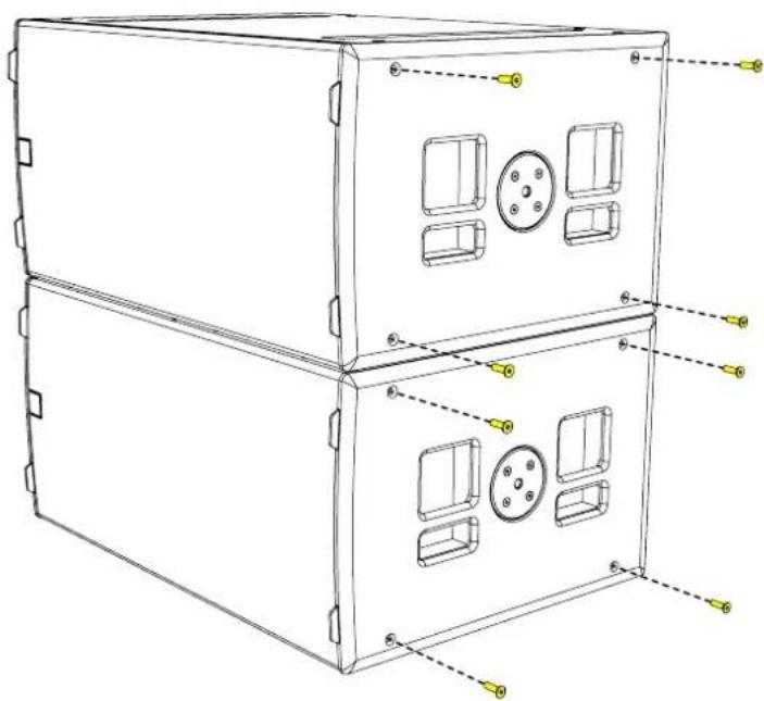
text_image
Technical diagram of a multi-chamber electronic device with labeled components and mounting pointsAttach the brackets, two on each with the "dog-leg" in the bracket at the top angled outwards using two M10 bolts and washers in each bracket.

natural_image
Technical line drawing of a multi-chamber air vent system with yellow connectors and mounting holes (no text or symbols)
natural_image
Technical line drawing of a multi-tiered industrial enclosure with yellow vertical connectors and internal compartments (no text or symbols)Next the SX218GRIDi should be attached to the two chain hoists that are being used to suspend the sub array. One point is required at the front and a second at the back. The hooks on the hoists can be attached using the two 3.25T Shackles supplied with the grid. Fly the grid out to a height so you can move the SX218 under it then lower the grid to line up the fixing holes on the grid with those on the brackets on the sub.
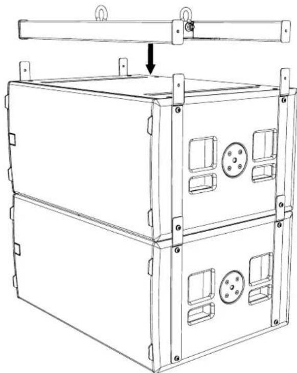
natural_image
Technical line drawing of a multi-tiered industrial enclosure with mounting brackets and internal compartments (no text or symbols)Join using the four M10 x 50 button head screws and washers supplied with the grid assembly. The sub can now be safely flow to the desired height.

natural_image
Technical line drawing of a multi-tiered industrial enclosure or storage unit with mounting holes and control panels (no text or symbols)A maximum of six SX218 subwoofers can be flown using this method.

natural_image
Technical line drawing of a multi-tiered rectangular electronic device with mounting brackets and internal compartments (no text or symbols)Transit Covers
The SX218 features an optional transit cover to protect the cabinet when used in portable applications.
To ensure that the insert is accurately located, four locating brackets are utilised. These are built into the cabinet in the four corners and maybe fitted in the parked position as standard. To use with the transit cover it is necessary to reverse the four brackets.
Remove the top and bottom safety screws from the grille. Insert a flat blade screwdriver into the slots of the grille and carefully easing the grille out of the slot.

natural_image
Line drawing of a rectangular electronic device casing with internal compartments and mounting holes (no text or symbols)
natural_image
Line drawing of a rectangular electronic device with internal compartments and a handle (no text or symbols)Remove the grille and screws on the side of the cabinet
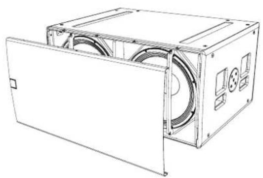
natural_image
Technical line drawing of a mechanical device with internal components and mounting holes (no text or symbols)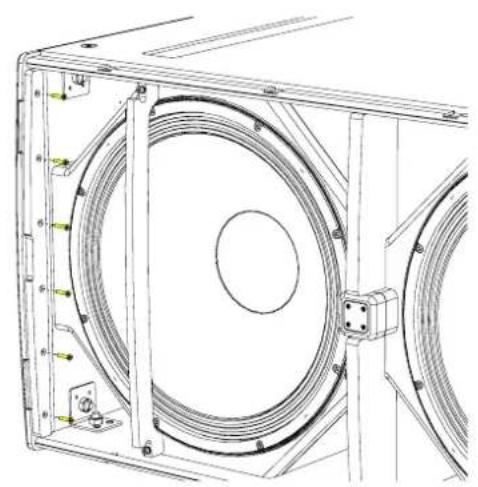
natural_image
Technical line drawing of a mechanical assembly with concentric circular components and mounting brackets (no text or symbols)Remove the grille support.
Remove the three screws from the bracket.
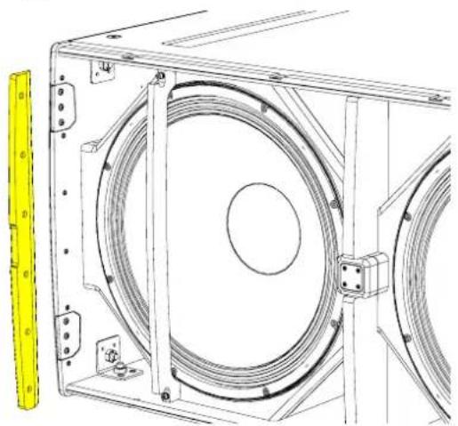
natural_image
Technical line drawing of a mechanical assembly with circular components and mounting brackets (no text or symbols)
natural_image
Technical line drawing of a mechanical assembly with no visible text or symbolsRotate the bracket 180°. The bracket will now extend approximately 20mm from the front edge of the cabinet, ensure that the slope on the bracket follows the curved contour of the cabinet.

natural_image
Technical line drawing of a mechanical assembly with no visible text or symbolsScrew the bracket back in place and repeat for the other three brackets.
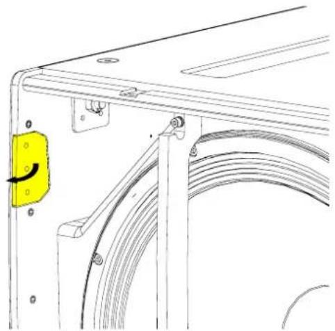
natural_image
Technical line drawing of a mechanical bracket with a yellow component and curved internal structure (no text or symbols)
natural_image
Technical line drawing of a mechanical bracket with attached wiring and mounting holes (no text or symbols)Replace the grill supports and fit the grille making sure the safety screws are replaced.
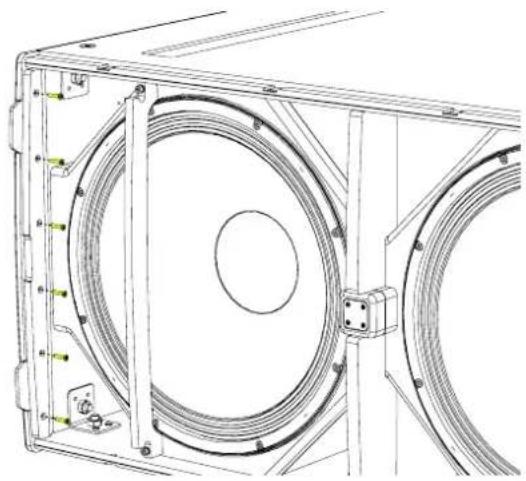
natural_image
Technical line drawing of a mechanical assembly with concentric circular components and mounting brackets (no text or symbols)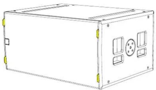
natural_image
Line drawing of a rectangular electronic device casing with mounting holes and internal compartments (no text or symbols)Castors
To fit the castors, remove the M8 counter-sunk screws from the rear of the enclosure.
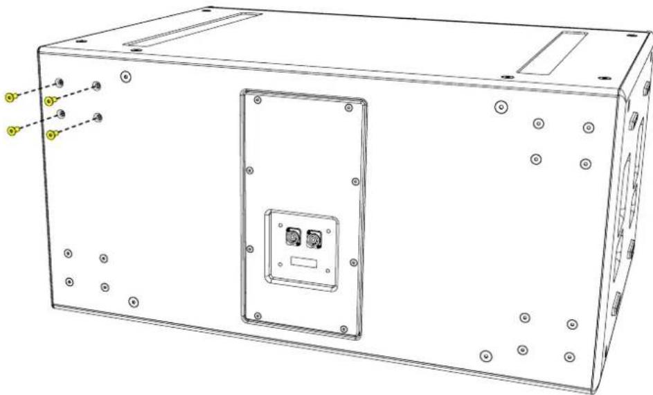
natural_image
Technical line drawing of a rectangular electronic device with mounting holes and internal components (no text or symbols)Position each castor over the insets and screw into place using the fixings supplied in the kit.
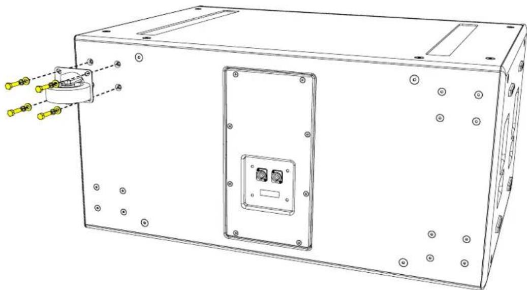
natural_image
Technical line drawing of a rectangular electronic device with mounting holes and internal components (no text or symbols)Weather Kit
The WRKIT for non-powered SX Series subwoofers is a glanded cover which fits over the connection panel to prevent water ingress protecting the NL4 speaker connection.
The cable entry may be through one of two knock-out positions depending the angle from which you wish the cable to enter. First remove the knock-out blank that you wish to use and fit the cable gland in position. Note that to use the WRKIT it is necessary to remove the NL4 connector from your speaker cable so the cable can be fed through the cable gland. Once the cable has been threaded through the gland the NL4 can be re-attached.
Remove the four counter-sunk screws in the connector panel and position the cover on the connector panel. Connect the NL4 to the input connector and position the cover, pulling the slack in the speaker cable as you lower the cover in position. Secure the cover using the four M4 x 25 cap socket screws and fibre washers. Finally tighten the gland to ensure a waterproof seal.
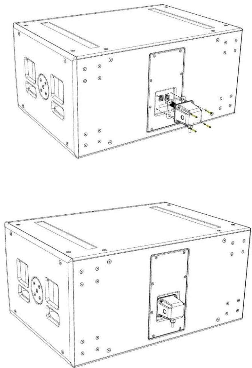
natural_image
Technical line drawings of a two-part electronic device casing with internal components and mounting holes (no text or symbols)Specifications
| TYPE Compact, direct radiating subwoofer | |
| FREQUENCY RESPONSE (1) 47Hz-150Hz ± 3dB, -10dB @ 41Hz | |
| DRIVER 1 x 18" (460mm)/4" (100mm) voice coil, long excursion, ferrite magnet, waterproof cone | |
| RATED POWER (2) 1000W AES, 4000W peak | |
| RECOMMENDED AMPLIFIER iK42 / iK81 | |
| SENSITIVITY (10) 102dB | |
| MAXIMUM SPL (9) 138dB continuous | |
| NOMINAL IMPEDANCE 8 ohms | |
| DISPERSION (-6dB) Omnidirectional | |
| CROSSOVER 80-120Hz active | |
| ENCLOSURE Multi-laminate birch/poplar plywood | |
| FINISH Textured black paint | |
| PROTECTIVE GRILLE Perforated steel | |
| CONNECTORS 2 x NL4 | |
| PIN CONNECTIONS (INPUT) LF1: +1, -1 LF2: +2, -2 | |
| PIN CONNECTIONS (LINK) LF1: +1, -1 LF2: +2, -2 | |
| FITTINGS | Two skids on base, with mating channels on top |
| Four rear-mounted 100mm (4in) castors | |
| 24 x M10 mounting points | |
| 4 x bar handles, 2 on each side | |
| 4 x fittings for optional transit cover | |
| DIMENSIONS (INCL FEET) | (W) 600mm x (H) 509mm x (D) 632mm (760mm including castors) |
| (W) 23.62in x (H) 20.04in x (D) 24.86in (29.9in including castors) | |
| WEIGHT | 47kg (104lbs) |
Technical Drawing
Notes
(1) Measured on-axis in half (2pi) space at 2 metres, then referred to 1 metre.
(2) AES Standard ANSI S4.26-1984.
(3) Measured in half (2pi) space at 2 metres with 1 watt input, using band limited pink noise, then referred to 1 metre.
(4) Measured in half (2pi) space at 2 metres using band limited pink noise, then referred to 1 metre.
(5) Measured on-axis in open (4pi) space at 2 metres, then referred to 1 metre.
(6) Measured in open (4pi) space at 2 metres with 1 watt input, using band limited pink noise, then referred to 1 metre.
(7) Measured in open (4pi) space at 2 metres using band limited pink noise, then referred to 1 metre.
(8) Measured in open (4pi) space at 2 metres with 2.83V input, using band limited pink noise, then referred to 1 metre.
(9) Calculated at 1 metre.
(10) Measured in half (2pi) space at 2 metres with 2.83V input, using band limited pink noise, then referred to 1 metre.

natural_image
Technical line drawing of a rectangular frame with two vertical slots and circular handles, no text or symbols present.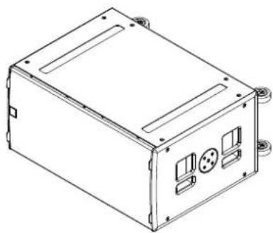
natural_image
Technical line drawing of a rectangular electronic device casing with mounting holes and internal compartments (no text or symbols)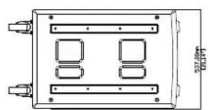
natural_image
Technical line drawing of a rectangular electronic component with four internal slots and mounting holes (no text or symbols)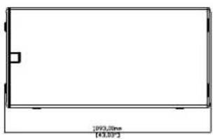
natural_image
Simple rectangular outline with no text, numbers, or symbols inside the shape (text not legible)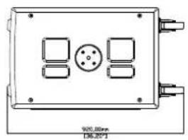
natural_image
Technical diagram of a rectangular electronic device with four ports and a central circular component (no text or symbols)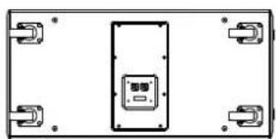
natural_image
Pure electrical circuit lines without any symbols
natural_image
Simple line drawing of a rectangular frame with two vertical bars and wheels, no text or symbols present.Castors are shown for illustration only and are not included as standard.
SXH218
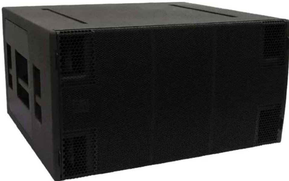
natural_image
Black rectangular electronic device casing with ventilation grilles and ventilation slots (no visible text or symbols)Introduction
The SXH218 is an extremely powerful subwoofer capable of producing 148dB peak output at 1m. It is the ideal partner for Wavefront Precision WPC arrays where maximum low frequency output is required as well as a standalone solution for premium permanent installations such as nightclubs.
Its Hybrid® horn/reflex loading combines the acoustic efficiency and impact of bass horn technology with the low frequency extension of a reflex design, enabling it to produce significantly higher output levels than a traditional reflex-loaded subwoofer. With an operating range of 32-150Hz + 3dB, it features dual long-excursion 18" (460mm)/4.5" (115mm) voice coil neodymium drivers, with water resistant cones and triple roll surrounds.
The enclosure is constructed from multi-laminate plywood and coated with hardwearing textured black polyurea. A rigid perforated steel grille protects the front of the enclosure, while interlocking skids protect the top and bottom surfaces and prevent movement when stacked.
The SXH218 can be powered by either a single channel of a Martin Audio iK42 4-channel amplifier, or a bridged pair if maximum output is required. Its connector sockets are wired so that one four-core cable from the amplifier will power two SXH218's. SXH218 settings are determined by a pre-determined parameter set in Vu-Net when used in conjunction with iK42, or settings are available from the Martin Audio website when used with alternative amplifiers.
By adding the input board cover accessory, the subwoofer is fully weather resistant and suitable for permanent outdoor usage.
Accessories
Transit cover SXH218TC
Weather kit WRKIT
Connections
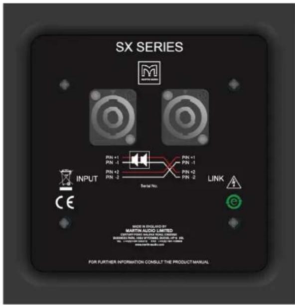
text_image
SX SERIES M MARTIN AUDIO INPUT CE PIN +1 PIN -1 PIN +2 PIN -2 Serial No. PIN +1 PIN -1 PIN +2 PIN -2 LINK Made in England by MARTIN AUDIO LIMITED DESCRIPTION: MARTIN AUDIO LIMITED RUSSES PER 100 VITOMEL DISCU PS 26 No. 13420758-0000, NO. 13420758-0000, NO. 13420758-0000, NO. 13420758-0000, NO. 13420758-0000, NO. 13420758-0000, NO. 13420758-0001, NO. 13420758-0001, NO. 13420758-0001, NO. 13420758-0001, NO. 13420758-0001, NO. 13420758-0001, NO. 13420758-01 FOR FURTHER INFORMATION CONSULT THE PRODUCT MANUALThe SXH218 is connected via a pair of NL4 connectors. This subwoofer features a unique wiring configuration which reverses the connections to the NL4 labelled 'LINK'. It is vital that connections to the iK42 amplifier are made to the INPUT NL4, if connecting to a second SXH218 connect from the 'LINK' out on the first subwoofer to the 'INPUT' on the second sub. Pins 1+/- on the Input are connected to pins 2+/- on the link and pins 2+/- on the input connected to pins 1+/- on the link. This configuration allows a neat cable solution using standard 4-core NL4 cables feeding two amplifier channels and ensuring that each sub is driven by one channel and not seeing a load impedance of less than 4Ω.
The following example shows wiring two SXH218 from independent channels of an iK42 with 4-core speaker cables.
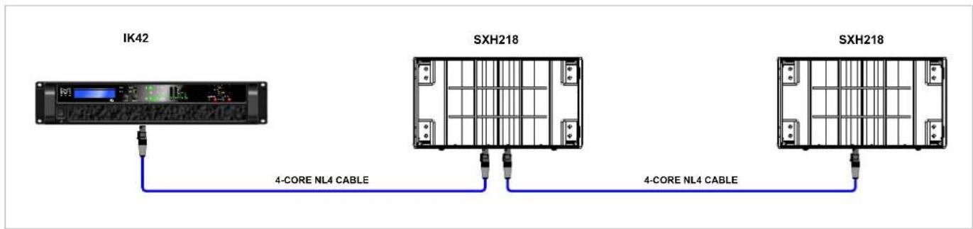
text_image
IK42 4-CORE NL4 CABLE SXH218 4-CORE NL4 CABLE SXH218SCHEMATIC
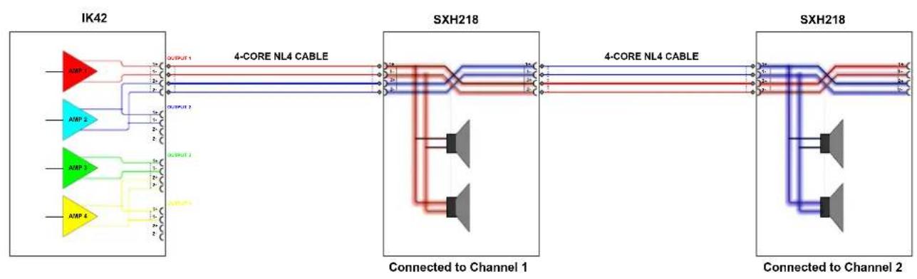
flowchart
graph LR
    subgraph IK42
        A1["AMP 1"] -->|OUTPUT 1| B1["4-CORE NL4 CABLE"]
        A2["AMP 2"] -->|OUTPUT 2| B1
        A3["AMP 3"] -->|OUTPUT 3| B1
        A4["AMP 4"] -->|OUTPUT 4| B1
    end

    subgraph SXH218
        B1 --> C1["Connected to Channel 1"]
        B1 --> C2["Connected to Channel 2"]
        B2["4-CORE NL4 CABLE"] --> C1
        B2 --> C2
    end

    subgraph SXH218
        C1 --> D1["Connected to Channel 1"]
        C2 --> D2["Connected to Channel 2"]
    end
Transit Covers
The SXH218 features an optional transit cover to protect the cabinet when used in portable applications.
To ensure that the insert is accurately located, four locating brackets are utilised. These are built into the cabinet in the four corners and maybe fitted in the parked position as standard. To use with the transit cover it is necessary to reverse the four brackets.
Remove the top and bottom safety screws from the grille. Insert a flat blade screwdriver into the slots of the grille and carefully easing the grille out of the slot.

natural_image
Technical line drawing showing two views of a mechanical component with no visible text or symbolsRemove the screws from the grille support on the side of the cabinet and remove the grille support.

natural_image
Line drawing of a cabinet or shelving unit with multiple shelves and doors (no text or symbols)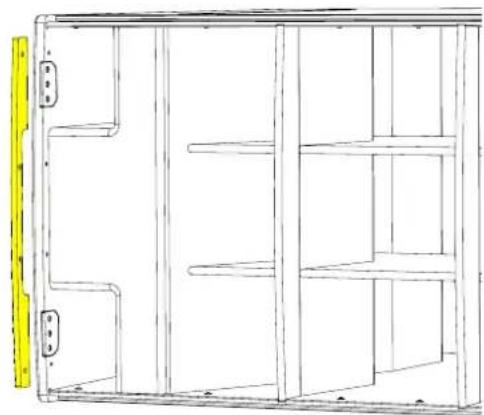
natural_image
Technical line drawing of a cabinet or storage unit with shelves and doors, no text or symbols presentRemove the three screws from the bracket.
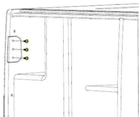
natural_image
Technical line drawing of a cabinet or enclosure with three labeled components (no text or symbols present)Rotate the bracket 180°. The bracket will now extend approximately 20mm from the front edge of the cabinet, ensure that the slope on the bracket follows the curved contour of the cabinet.

natural_image
Technical line drawing of a structural frame with a yellow component on the left side (no text or symbols)Screw the bracket back in place and repeat for the other three brackets.

natural_image
Technical line drawing of a structural frame with metal supports and a bracket (no text or symbols)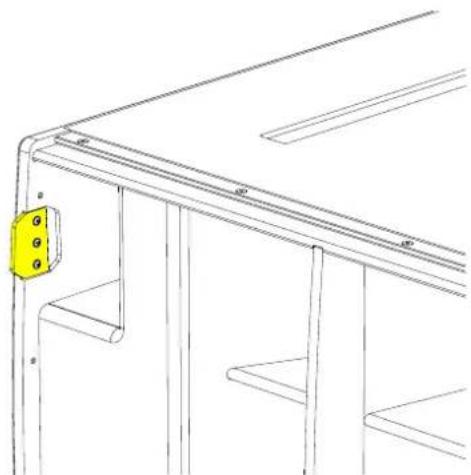
natural_image
Technical line drawing of a structural frame with a yellow bracket and mounting holes (no text or symbols)Replace the grill supports and fit the grille making sure the safety screws are replaced.

natural_image
Line drawing of a cabinet or storage unit with multiple shelves and mounting holes (no text or symbols)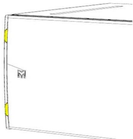
natural_image
Simple line drawing of a folded paper or document with a yellow bookmark and a black header (no text or symbols)Weather Kit
The WRKIT for non-powered SX Series subwoofers is a glanded cover which fits over the connection panel to prevent water ingress protecting the NL4 speaker connection.
The cable entry may be through one of two knock-out positions depending the angle from which you wish the cable to enter. First remove the knock-out blank that you wish to use and fit the cable gland in position. Note that to use the WRKIT it is necessary to remove the NL4 connector from your speaker cable so the cable can be fed through the cable gland. Once the cable has been threaded through the gland the NL4 can be re-attached.
Remove the four counter-sunk screws in the connector panel and position the cover on the connector panel. Connect the NL4 to the input connector and position the cover, pulling the slack in the speaker cable as you lower the cover in position. Secure the cover using the four M4 x 25 cap socket screws and fibre washers. Finally tighten the gland to ensure a waterproof seal.
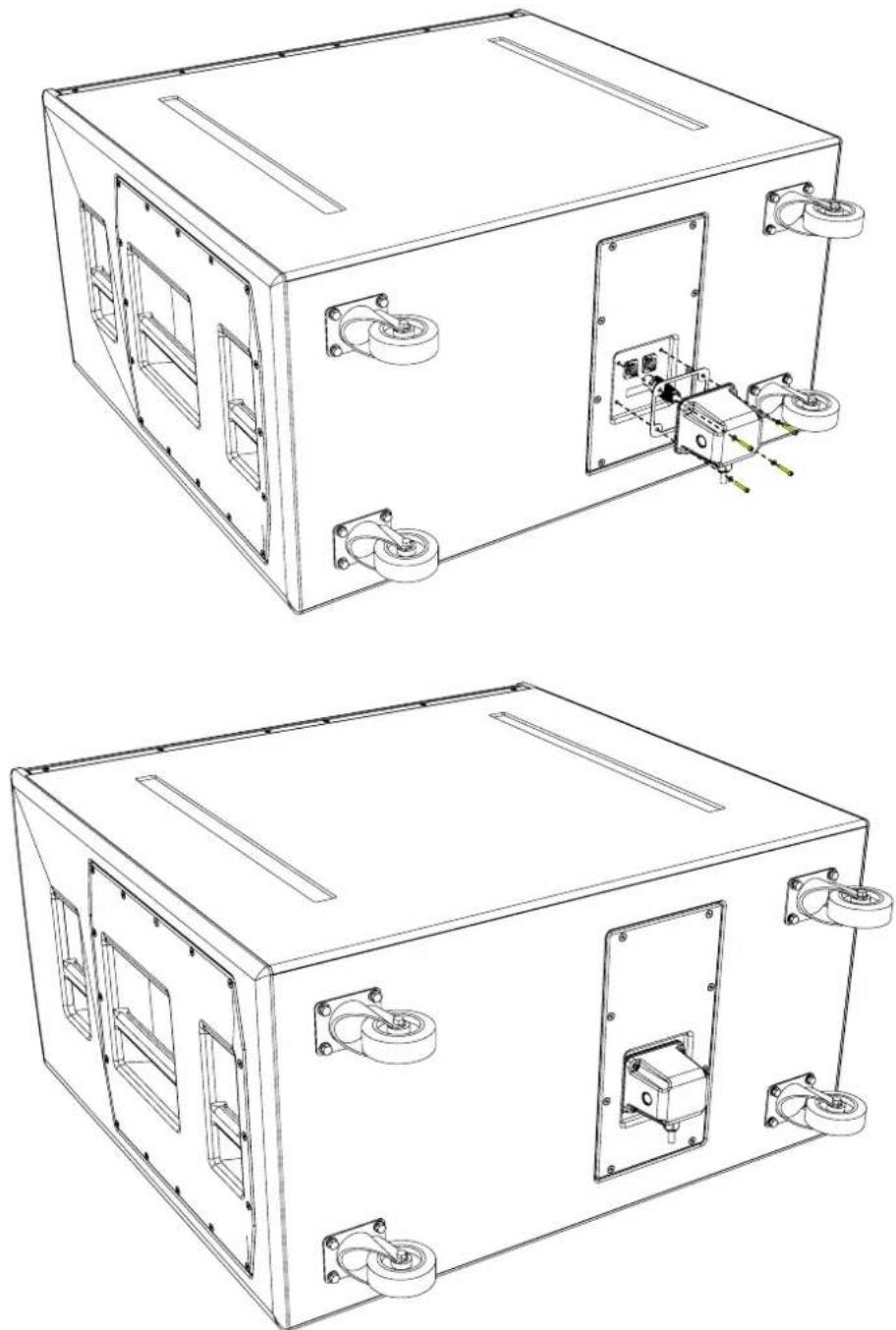
natural_image
Technical line drawings of a rectangular electronic device with mounting holes and internal components (no text or symbols)Specifications
TYPE Hybrid horn/reflex subwoofer
FREQUENCY RESPONSE (1) 32Hz-150Hz ± 3dB, -10dB @ 27Hz
DRIVER 2 x 18" (460mm)/4.5" (115mm) voice coil, long excursion, neodymium magnet, waterproof cone
RATED POWER (2) 3000W AES, 12000W peak
RECOMMENDED AMPLIFIER iK42
SENSITIVITY (10) 107dB
MAXIMUM SPL (9) 148dB peak (at 1m half space)
NOMINAL IMPEDANCE 4 ohms
DISPERSION (-6dB) Omnidirectional
CROSSOVER 80-120Hz active
ENCLOSURE Multi-laminate birch/poplar plywood
FINISH Textured black paint
PROTECTIVE GRILLE Perforated steel
CONNECTORS 2 x NL4
PIN CONNECTIONS (INPUT) +1, -1, refer to input panel for four-core cable link diagram
FITTINGS Two skids on base, matching channels on top. 4 x bar handles
Four rear-mounted 100mm (4in) castors
4 x fittings for optional transit cover
DIMENSIONS (INCL FEET) (W) 1112mm x (H) 607mm x (D) 1013mm (1140mm including castors)
(W) 43.8in x (H) 23.9in x (D) 39.9in (44.9in including castors)
WEIGHT 124kg (273lbs)
Notes
(1) Measured on-axis in half (2pi) space at 2 metres, then referred to 1 metre.
(2) AES Standard ANSI S4.26-1984.
(3) Measured in half (2pi) space at 2 metres with 1 watt input, using band limited pink noise, then referred to 1 metre.
(4) Measured in half (2pi) space at 2 metres using band limited pink noise, then referred to 1 metre.
(5) Measured on-axis in open (4pi) space at 2 metres, then referred to 1 metre.
(6) Measured in open (4pi) space at 2 metres with 1 watt input, using band limited pink noise, then referred to 1 metre.
(7) Measured in open (4pi) space at 2 metres using band limited pink noise, then referred to 1 metre.
(8) Measured in open (4pi) space at 2 metres with 2.83V input, using band limited pink noise, then referred to 1 metre.
(9) Calculated at 1 metre.
(10) Measured in half (2pi) space at 2 metres with 2.83V input, using band limited pink noise, then referred to 1 metre.
Technical Drawing

natural_image
Pure technical line drawing of a rectangular enclosure with two vertical supports and mounting feet (no text or symbols)
natural_image
Isometric line drawing of a rectangular electronic device with internal compartments and ventilation slots (no text or symbols)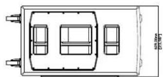
natural_image
Top-down schematic of a vehicle chassis with front seats and rear wheels (no text or symbols)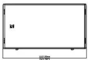
text_image
M 100.50m [0.3,9°]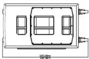
natural_image
Technical line drawing of a rectangular device with internal compartments and mounting points (no text or symbols)
natural_image
Simple line drawing of a rectangular panel with four corner connectors (no text or symbols)
natural_image
Simple line drawing of a rectangular box with two vertical bars and wheels (no text or symbols)SXHF218
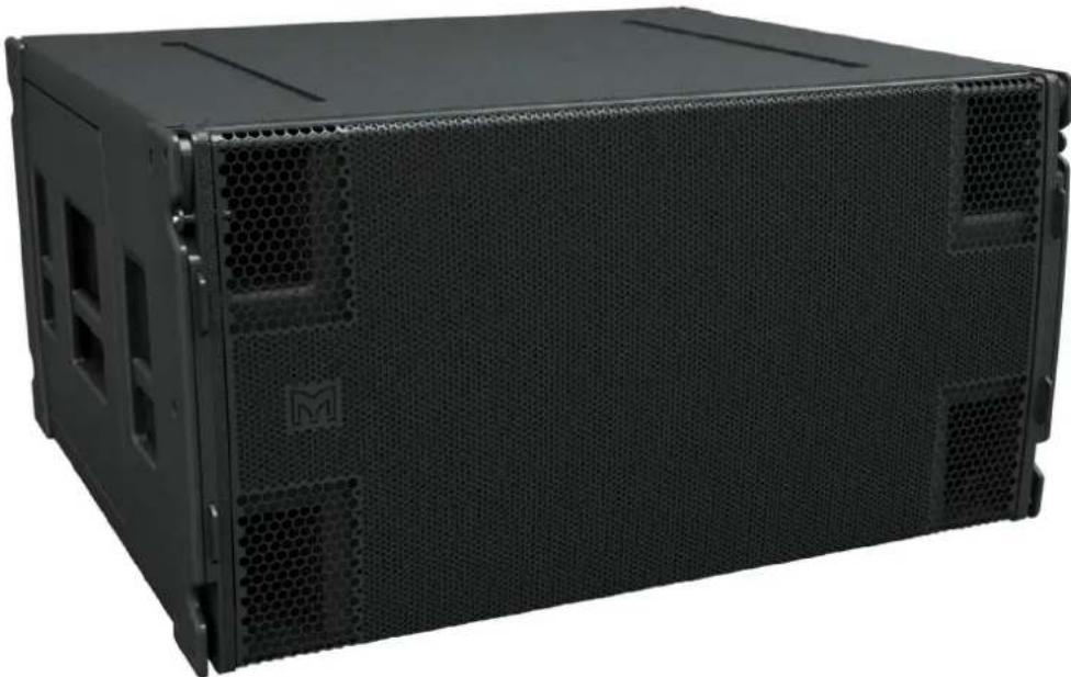
natural_image
Black server rack unit with hexagonal ventilation grilles and a M logo on the front panel (no visible text or symbols)Introduction
The SXHF218 is an extremely powerful subwoofer capable of producing 148dB peak output at 1m. It is the ideal partner for Wavefront Precision WPC and WPL arrays where maximum low frequency output is required as well as a standalone solution for premium permanent installations such as nightclubs.
Its Hybrid® horn/reflex loading combines the acoustic efficiency and impact of bass horn technology with the low frequency extension of a reflex design, enabling it to produce significantly higher output levels than a traditional reflex-loaded subwoofer. With an operating range of 32-150Hz + 3dB, it features dual long-excursion 18" (460mm)/4.5" (115mm) voice coil neodymium drivers, with water resistant cones and triple roll surrounds.
The enclosure is constructed from multi-laminate plywood and coated with hardwearing textured black polyurea. A rigid perforated steel grille protects the front of the enclosure, while interlocking skids protect the top and bottom surfaces and prevent movement when stacked.
The SXH218 can be powered by either a single channel of a Martin Audio iK42 4-channel amplifier, or a bridged pair if maximum output is required. Its connector sockets are wired so that one four-core cable from the amplifier will power two SXH218's. SXH218 settings are determined by a pre-determined parameter set in Vu-Net when used in conjunction with iK42, or settings are available from the Martin Audio website when used with alternative amplifiers.
By adding the input board cover accessory, the subwoofer is fully weather resistant and suitable for permanent outdoor usage.
Accessories
M10 eyebolts HTKCT06
Transit cover SXH218TC
Weather kit WRKIT
Flying frame WPLGRIDt
Connections
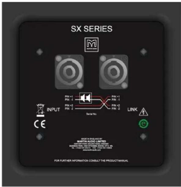
text_image
SX SERIES M MARTIN AUDIO INPUT CE PIN +1 PIN -1 PIN +2 PIN -2 Serial No. PIN +1 PIN -1 PIN +2 PIN -2 LINK Made in England by MARTIN AUDIO LIMITED CONTROL (MINTIN) MAXIMUM LINES RASSIS MAX. 100 VYTOMES, MAX. 100% 100% NO. 100000000000000000000000000000000000000000000000000000000000000000 FOR FURTHER INFORMATION CONSULT THE PRODUCT MANUALThe SXHF218 is connected via a pair of NL4 connectors. This subwoofer features a unique wiring configuration which reverses the connections to the NL4 labelled 'LINK'. It is vital that connections to the iK42 amplifier are made to the INPUT NL4, if connecting to a second SXH218 connect from the 'LINK' out on the first subwoofer to the 'INPUT' on the second sub. Pins 1+/- on the Input are connected to pins 2+/- on the link and pins 2+/- on the input connected to pins 1+/- on the link. This configuration allows a neat cable solution using standard 4-core NL4 cables feeding two amplifier channels and ensuring that each sub is driven by one channel and not seeing a load impedance of less than 4Ω.
The following example shows wiring two SXH218 from independent channels of an iK42 with 4-core speaker cables.
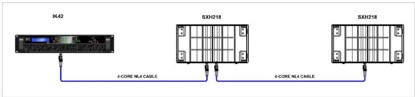
flowchart
graph LR
    A["IK42"] -->|4-CORE NL4 CABLE| B["SXH218"]
    B -->|4-CORE NL4 CABLE| C["SXH218"]
SCHEMATIC
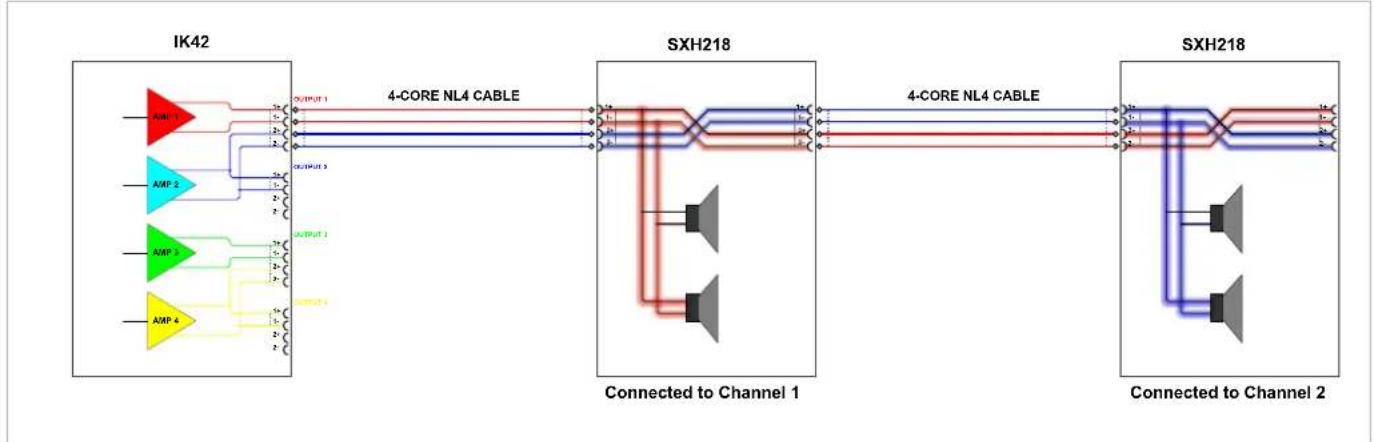
flowchart
graph LR
    A["IK42"] --> B["4-CORE NL4 CABLE"]
    B --> C["SXH218"]
    C --> D["4-CORE NL4 CABLE"]
    D --> E["SXH218"]
    subgraph Channel 1
        F["AMP 1"] --> G["OUTPUT 1"]
        H["AMP 2"] --> I["OUTPUT 2"]
        J["AMP 3"] --> K["OUTPUT 3"]
        L["AMP 4"] --> M["OUTPUT 4"]
    end
    subgraph Channel 2
        N["AMP 1"] --> O["OUTPUT 1"]
        P["AMP 2"] --> Q["OUTPUT 2"]
        R["AMP 3"] --> S["OUTPUT 3"]
        T["AMP 4"] --> U["OUTPUT 4"]
    end
Flying SXHF218
WPLGRIDt
Using one or two motors position a WPLGRIDt above the SCXF118 and lower it onto the enclosure.

natural_image
Technical line drawing of a mechanical assembly with two components and a downward arrow indicating motion (no text or symbols)Replace the WPLGRIDt pins to link the SXHF218 securely to the WPLGRIDt. The SXHF218 pins for the first cabinet are not needed in this configuration and can be placed back in the stowed position.
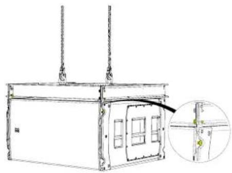
natural_image
Technical line drawing of a rectangular industrial or mechanical device with suspended components and a magnified inset showing internal structure (no text or symbols)Remove the pins from the stow position, rotate the links to line up with the pin hole position on the SXHF218 above.

natural_image
Technical line drawing of a multi-story building with structural details and an inset showing a cross-section of a pipe or pipe junction (no text or symbols present)Remove the 4 link pins from the WPLGRIDt and also remove the 4 pins from the from SXHF218 to release the links. Rotate the SXHF218 links and line them up with the pin holes in the WPLGRIDt.
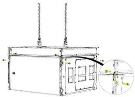
natural_image
Technical line drawing of a rectangular industrial or logistics container with hanging chains and a small inset showing a curved pipe or pipe connection (no text or symbols present)Raise the WPLGRIDt and SXHF218 to a height suitable to fit another SXHF218 below the array, lower it making sure the protective nylon skids line up and fit into the recessed channels on the SXHF218 below.

natural_image
Diagram showing a container being lifted by a crane, with an arrow indicating the process (no text or symbols present)Replace the pins into the lock position on the cabinet above making sure all four links are securely attached. Repeat the process until the correct amount of SXHF218's are flown, the maximum number is 16 SXHF218.
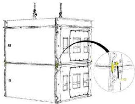
text_image
Technical diagram of a multi-story industrial container with a magnified inset showing internal structure and component details.Transit Covers
The SXH218 features an optional transit cover to protect the cabinet when used in portable applications.
To ensure that the insert is accurately located, four locating brackets are utilised. These are built into the cabinet in the four corners and maybe fitted in the parked position as standard. To use with the transit cover it is necessary to reverse the four brackets.
Remove the top and bottom safety screws from the grille. Insert a flat blade screwdriver into the slots of the grille and carefully easing the grille out of the slot.
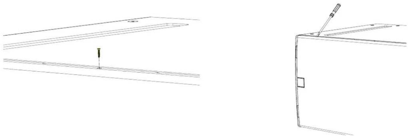
natural_image
Technical line drawing showing two views of a mechanical component with no visible text or symbolsRemove the screws from the grille support on the side of the cabinet and remove the grille support.

natural_image
Line drawing of a cabinet or shelving unit with shelves and doors (no text or symbols)
natural_image
Technical line drawing of a cabinet or storage unit with shelves and doors, no text or symbols presentRemove the three screws from the bracket.

natural_image
Technical line drawing of a mechanical assembly with no visible text or symbolsRotate the bracket 180°. The bracket will now extend approximately 20mm from the front edge of the cabinet, ensure that the slope on the bracket follows the curved contour of the cabinet.
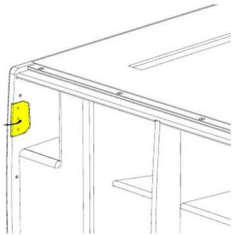
natural_image
Technical line drawing of a structural frame with a yellow component on the left side (no text or symbols)Screw the bracket back in place and repeat for the other three brackets.
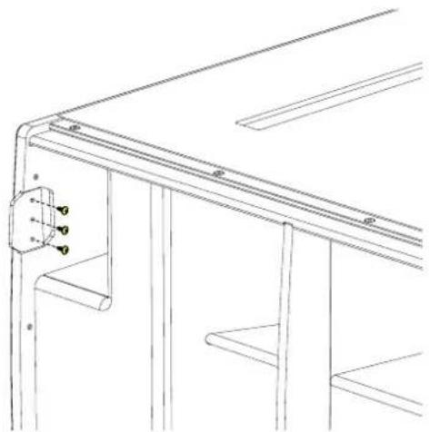
natural_image
Technical line drawing of a structural frame with metal supports and a bracket (no text or symbols)
natural_image
Technical line drawing of a structural frame with a yellow bracket and mounting holes (no text or symbols)Replace the grill supports and fit the grille making sure the safety screws are replaced.
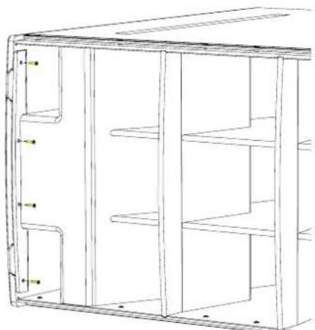
natural_image
Line drawing of a cabinet or storage unit with multiple shelves and mounting holes (no text or symbols)
natural_image
Simple line drawing of a folded paper or document with a yellow bookmark and a black header (no text or symbols)Weather Kit
The WRKIT for non-powered SX Series subwoofers is a glanded cover which fits over the connection panel to prevent water ingress protecting the NL4 speaker connection.
The cable entry may be through one of two knock-out positions depending the angle from which you wish the cable to enter. First remove the knock-out blank that you wish to use and fit the cable gland in position. Note that to use the WRKIT it is necessary to remove the NL4 connector from your speaker cable so the cable can be fed through the cable gland. Once the cable has been threaded through the gland the NL4 can be re-attached.
Remove the four counter-sunk screws in the connector panel and position the cover on the connector panel. Connect the NL4 to the input connector and position the cover, pulling the slack in the speaker cable as you lower the cover in position. Secure the cover using the four M4 x 25 cap socket screws and fibre washers. Finally tighten the gland to ensure a waterproof seal.
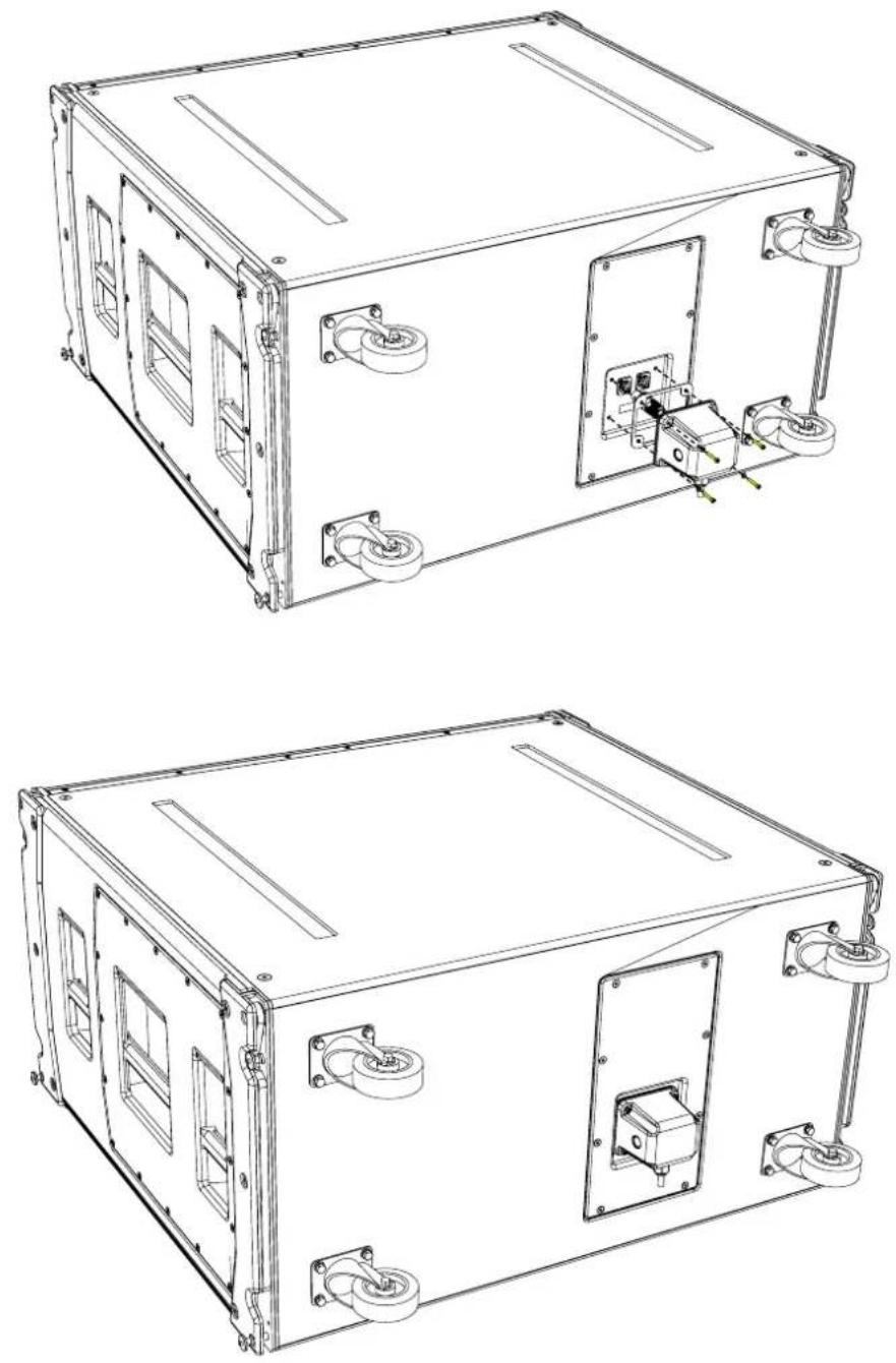
natural_image
Technical line drawings of a two-port electrical enclosure with mounting brackets and internal components (no text or symbols)Specifications
TYPE Hybrid horn/reflex subwoofer
FREQUENCY RESPONSE (1) 32Hz-150Hz ± 3dB, -10dB @ 27Hz
DRIVER 2 x 18" (460mm)/4.5" (115mm) voice coil, long excursion, neodymium magnet, waterproof cone
RATED POWER (2) 3000W AES, 12000W peak
RECOMMENDED AMPLIFIER IKON iK42
SENSITIVITY (10) 107dB
MAXIMUM SPL (9) 148dB peak (at 1m half space)
NOMINAL IMPEDANCE 4 ohms
DISPERSION (-6dB) Omnidirectional/or Cardioid (paired)
CROSSOVER 80-120Hz active
ENCLOSURE Multi-laminate birch/poplar plywood
FINISH Textured black Polyurea
PROTECTIVE GRILLE Black perforated steel
CONNECTORS 2 x NL4
PIN CONNECTIONS (INPUT) +1, -1, refer to input panel for four-core cable link diagram
FITTINGS Two skids on base, matching channels on top. 4 x bar handles
Four rear-mounted 100mm (4in) castors
4 x fittings for optional transit cover
DIMENSIONS (INCL SKIDS) (W) 1148mm x (H) 604mm x (D) 1027mm (1155mm including castors)
(W) 45.2in x (H) 23.8in x (D) 40.4in (45.5in including castors)
WEIGHT 138kg (204lbs), with castors 146.5kg (323lbs)
Notes
(1) Measured on-axis in half (2pi) space at 2 metres, then referred to 1 metre.
(2) AES Standard ANSI S4.26-1984.
(3) Measured in half (2pi) space at 2 metres with 1 watt input, using band limited pink noise, then referred to 1 metre.
(4) Measured in half (2pi) space at 2 metres using band limited pink noise, then referred to 1 metre.
(5) Measured on-axis in open (4pi) space at 2 metres, then referred to 1 metre.
(6) Measured in open (4pi) space at 2 metres with 1 watt input, using band limited pink noise, then referred to 1 metre.
(7) Measured in open (4pi) space at 2 metres using band limited pink noise, then referred to 1 metre.
(8) Measured in open (4pi) space at 2 metres with 2.83V input, using band limited pink noise, then referred to 1 metre.
(9) Calculated at 1 metre.
(10) Measured in half (2pi) space at 2 metres with 2.83V input, using band limited pink noise, then referred to 1 metre.
Technical Drawing

natural_image
Simple line drawing of a rectangular frame with vertical supports and circular ends (no text or symbols)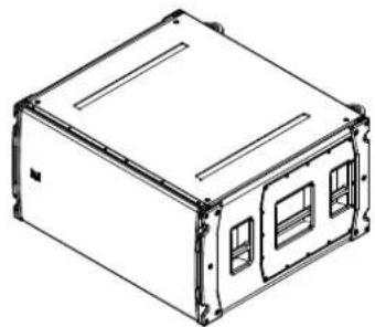
natural_image
Line drawing of a rectangular electronic device casing with mounting flanges and internal compartments (no text or symbols)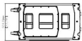
natural_image
Top-down schematic of a vehicle chassis with four compartments and mounting points (no text or labels)
text_image
图 1,45.20× [0.25]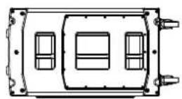

natural_image
Technical line drawing of a rectangular enclosure with mounting holes and a central control panel (no text or symbols)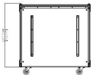
natural_image
Technical line drawing of a rectangular frame with two vertical supports and wheels, no text or symbols present.SXP118
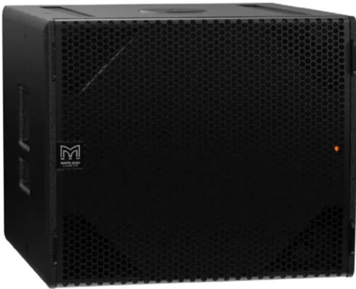
natural_image
Black rectangular electronic device with hexagonal grid pattern and 'MARTIN RADIO STAFFER' logo on front (no readable text beyond branding)Introduction
The SXP118 is a compact, high-performance subwoofer that extends the low frequency operating range of a CDD-LIVE full-range system to 40Hz — providing exceptional low frequency impact and increasing headroom. It features a long-excursion 18" (460mm)/4" (100 mm) voice coil driver with a water-resistant cone and triple roll surround in a compact reflex enclosure.
The design of the 18" driver maximises output while minimising power compression and distortion, and the four reflex ports have a large frontal area to reduce turbulent air noise at very high levels. With a maximum SPL capability of 135dB peak at 1 metre, the SXP118 is the ideal subwoofer for theatre and portable live sound applications, as well as premium installations that require the maximum output from a compact enclosure.
A self-powered system, the SXP118 incorporates a Class D amplifier, DSP and Dante™ digital audio networking — simplifying set-up, enhancing control and eliminating amplifier racks. The onboard amplifier delivers 2000W peak output to the driver, and its switched-mode power supply auto-ranges to global mains voltages from 100 to 240V 50/60Hz. DSP functions — including parametric EQ, delay, muting, gain and preset selection — can be controlled over Ethernet from a PC or Windows® tablet via intuitive VU-NET™ proprietary software.
Accessories
M10 eyebolts HTKCT06
Transit cover SXTC118
Castor kit WHEELKIT
Wind-up pole ASF20071
Weather kit CDDLRK118/218
Connections
The SXP118 is a powered subwoofer and shares its connections with the CDD-LIVE range. There are three types of connection on each sub, consisting of mains, analogue XLR and Network Ethercon.
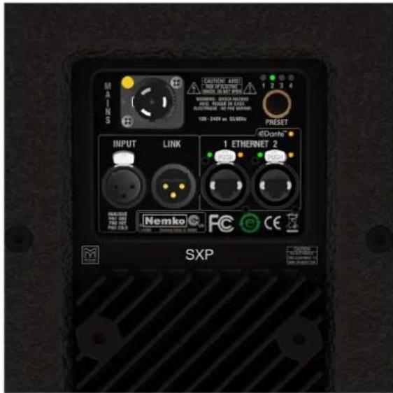
text_image
MAINS CAUTIONAL ADDI NEW OF ELECTRIC INCHES ON SET POWER POWER: 100V AC/DC 500W PRESER: 240V AC/DC 500W PRET. 1 2 3 4 100V AC/DC 500W PRESET INPUT LINK 1 ETHERNET 2 Nemko FC CE SXPMains
The mains inlet is a Neutrik® PowerCon True1 socket and a mating connector is supplied with each CDD-LIVE speaker. The True1 is the latest version of Neutrik's PowerCon range and is a small, light, rugged, inexpensive latching mains connector rated for use up to 240V at 16A. It is rated with a breaking capacity according to IEC60320 and VDE0625 meaning that it can be connected and disconnected without first turning off the power feed. This has the advantage of being very convenient but also makes a power switch unnecessary as it is easy to turn the speaker off by activating the latch and turning the connector anticlockwise which will disconnect the power whilst leaving the plug in place in the socket so it can be quickly rotated clockwise to restore the power connection when required.

text_image
APPLIANCE INLET POWER IN NAC3MPX NAC3FX-W or NKPF (Connector) CABLE EXTENTION NAC3FX-W or NKPF (Connector) NAC3MX-W or NKPM (Plug connector)Wiring Instructions
Wiring instructions for the Neutrik PowerCon True1 are as follows. Note that all mains wiring should be carried out by a competent, trained technician. If a suitable technician is not available Martin Audio would recommend purchasing one of the range of pre-made mains cables available as optional accessories. These feature the PowerCon True1 connector on a flexible cable of either 2.15m (part number ASF12024) or 5m (part number ASF12023) in length and are terminated in a 16A male Ceform connector. Both cables are rated to IP67.
| Approval based: VDE | EN 60320 | ULUL 498 / C22.2 No. 182.3 |
| Rating: 250 V ac / 16A 250 V ac / 20 A | ||
| Cable Type: H05VV-F3G 1.0mm2, Length max. 2mH05VV-F3G 1.5 – 2.5mm2H07RN-F3G 1.5mm2 | SJTOW, SJ00W 3 x 12 AWG | |
| Strain Relief: White Chuck White Chuck | ||
| Cable O.D.: 6.0 – 12.0 mm 6.0 – 12.0 mm | ||
| A: Prepare cable as shown. | 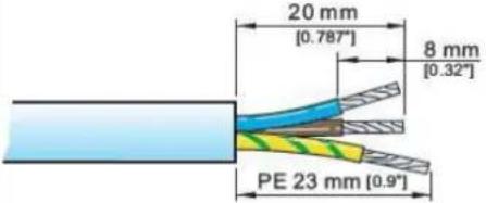 | 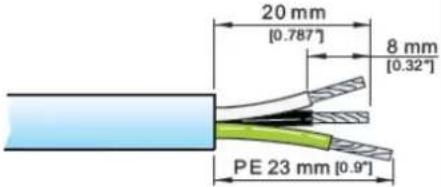 |
| B: Place chuck over cable. |  | |
| C: Wire the connectorUsing a Torx T8 driver, the xing screws should be tightened to a torque value of 0.7Nm. |  | |
| LiveNeutralGround | BrownBlueGreen/yellow | BlackWhiteGreen |
| D: Assemble the connectorSlide the chuck onto insert and then both into the housing.Note: Align the chuck by positioning the nose into the keyway. |  | ||
| E: Tighten the cable clampSlide the cable clamp up the cable and tighten. To wire the connector to IP65, the cable clamp needs to be tightened to a torque value of 2.0Nm using the Neutrik tool no. HTAC with a 13mm spanner. | 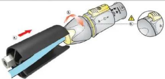 | ||
| DisassemblyPress a small flat-blade screwdriver into the cable clamp bush by the ☐ symbol, continue to push the screwdriver in whilst unscrewing the clamp. | 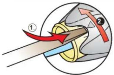 |
Analogue Audio
Analogue audio is available on a 3-pin XLR socket with a parallel male XLR socket to enable easy "daisy-chain" wiring looping from one speaker to the next. Analogue inputs should be connected with a good quality 3-pin male XLR wired to good quality twin screened cable. This is particularly important if the input cable run is long (e.g., from the FOH position to stage). Good quality cable will minimise losses. The link outputs should use a similarly high quality female XLR. The line driver at the signal source must be able to drive the combined load of all SXP subwoofers or CDD-LIVE being linked. Wiring is the industry standard for balanced connections:
| PIN CONNECTION |
| 1 Ground or shield |
| 2 Signal 'hot' ('+') |
| 3 Signal 'cold' ('-') |
Network
Two network ports are available to control the subwoofer via Martin Audio's VU-NET software and to route Dante audio to each sub. The two Ethernet ports are available on Neutrik Ethercon connectors which can be used either with a compatible mating connector or directly with a CAT5 cable with RJ45 connectors. The connections are routed to a two-port switch which enables daisy-chain Ethernet/Dante connections of up to 8 cabinets. Alternatively, a star network configuration can be adopted using any Gigabit enabled Ethernet router connecting individual Ethernet cables to each cabinet. Note that the ports can carry both Dante and TCP/IP data simultaneously so a Dante network can be set up with control over all CDD-LIVE cabinets via VU-NET.
Note that you must use a network system that supports DHCP to connect multiple CDD-LIVE products, a simple Ethernet switch will NOT work unless the entire system is configured for static IP, you will need an Ethernet router or a device connected to an Ethernet switch which will support DHCP to assign IP addresses to all devices on the network. You can connect directly from a PC Ethernet port to ONE CDD-LIVE cabinet which will self-assign an IP address in the same range as the PC. This takes around one minute and after that it will be possible to connect to the cabinet via VU-NET. You CANNOT daisy-chain more CDD-LIVE cabinets in this configuration. It can only be used with a single cabinet so its use is limited to simple checks or firmware updates.
Dante is realised using the Ultimo board, this does not support primary and secondary connections but redundancy is possible using an analogue audio feed simultaneously with a Dante network. The input will automatically select Dante is a signal is present however it will automatically switch to the analogue feed if the Dante signal is lost. The Ethernet ports have standard LED indicators to show operation. The green LEDs show that the port is operational and should illuminate as soon as a connection is made to or from an Ethernet port from any other port. The yellow LEDs flash to show data speed. The Dante LED will illuminate when a Dante feed is present.
Preset Operation
SXP118 can be fully configured using VU-NET on an Ethernet network. Alternatively plug-and-play operation is available using factory presets selected using the preset button on the connector panel.

text_image
MATERIALS INPUT LINK 10V-240W 30.0MHz 1 2 3 4 PRESET @Danta® 1 ETHERNET 2 Nemko SXPPreset 1 - SXP118 used in conjunction with CDD-LIVE12 or CDD-LIVE15:

text_image
1 2 3 4Preset 2 - SXP118 used in conjunction with CDD-LIVE8:

text_image
1 2 3 4Preset 3 - SXP118 used in conjunction with CDD-LIVE12 or CDD-LIVE15 in cardioid (rear facing) mode:

text_image
1 2 3 4Preset 4 - SXP118 used in conjunction with CDD-LIVE8 in cardioid (rear facing) mode:

text_image
1 2 3 4Note that the selected preset is retained after powering down the SXP118. The same preset will still be selected when you next power-up the cabinet.
When a system is connected to VU-NET via the Ethernet ports the preset LEDs will be extinguished to show that the system settings may have been changed. To restore the preset once VU-NET is disconnected press the preset button until it has cycled round to the preset you require. Any changes made in VU-NET will then be overwritten with the factory setting.
Meter Mode
An additional feature is meter mode which is selected by pressing and holding the preset select button for two seconds. In this mode the LEDs which normally indicate which preset has been selected, become an input level bar graph to show level applied to the speaker. To return to normal preset selection, press and hold again for two seconds.
Dante
SXP118 can be fed via a Dante feed on an Ethernet network. Hundreds of Dante-enabled products are available, enabling you to mix devices from multiple manufacturers.
Dante does away with heavy, expensive analogue or multicore cabling, replacing it with low-cost, easily-available CAT5e, CAT6, or fibre optic cable for a simple, lightweight and economical solution. Dante integrates media and control for your entire system over a single, standard IP network.
Dante systems can easily scale from a simple pairing of a console to a computer, to large capacity networks running thousands of audio channels. Because Dante uses logical routes instead of physical point-to-point connections, the network can be expanded and reconfigured at any time with just a few mouse clicks.
Since audio is transmitted digitally, you don't have to worry about the common analogue challenges of interference from other electrical equipment, crosstalk between cables, or signal degradation over long cable runs.
Signal routing and system configuration with Dante Controller can be fast, simple. Setting up a Dante network is typically just a matter of plugging devices into an Ethernet switch and connecting a computer to the network. All Dante devices are automatically discovered and displayed in Dante Controller
With Dante Controller you can easily edit device names and channel labels, control sample rates, and set device latencies. Once the network is configured, the computer running Dante Controller can be removed from the network, and reconnected only if changes are required or system monitoring is desired. Signal routing and other system settings are stored safely in the Dante devices themselves, so they are automatically restored if a device is power-cycled.
Real-time information about the health of your network is essential for a proper understanding of its performance. Audinate's diagnostic tools provide visibility into the network health status through features such as device latency monitoring, active clock health monitoring, packet error reporting and bandwidth usage statistics.
VU-NET
SXP118 may be controlled using Martin Audio's VU-NET software application. VU-NET is Martin Audio's proprietary application for control of monitoring of network controlled powered products. Introduced as the control platform for MLA, MLA Compact and MLA Mini, a number of products have been added to Martin Audio's portfolio that can be incorporated into a single project and configured using VU-NET. SXP118 subwoofers in combination with the CDD-LIVE Series are fully integrated into the platform.
For further information and instruction on VU-NET and to download the application and user guide, please visit www.martin-audio.com/software.
Flying SXP118
Eyebolts
The SXP118 features M10 inserts to allow flown applications using eyebolts. M10 eyebolts suitable for flown systems are available as accessories from Martin Audio. These are cast steel shouldered eye bolts specifically designed and rated for flown applications. If alternative eyebolts are used these must be cast or machined products stamped with their SWL. Formed steel non-shouldered eyebolts commonly available from DIY stores should not be used under any circumstances as they are not sufficiently load-rated for flown applications.

natural_image
Line drawing of a rectangular electronic device with mounting holes and internal compartments (no text or symbols)Remove the M10 counter-sunk screws and screw the eyebolts into position. We would recommend four eyebolts and an additional eyebolt as a redundant safety bond. This should be attached to a different point than the other bolts to support the cabinet in the event of the other points failing.
Eyebolts should be connected to a suitably rated fixing point such as a girder clamp or a heavy duty fixing such as a sleeve anchor or similar. They can be linked using suitably rated steel rope or chain and shackles.
Safety note: Flying heavy equipment in public spaces is dangerous and should only be undertaken by suitably qualified and experienced personnel using adequately rated equipment for the task.
Transit Covers
The SXP118 features an optional transit cover to protect the cabinet when used in portable applications.
To ensure that the insert is accurately located, four locating brackets are utilised. These are built into the cabinet in the four corners and maybe fitted in the parked position as standard. To use with the transit cover it is necessary to reverse the four brackets.
Remove the top and bottom safety screws from the grille. Insert a flat blade screwdriver into the slots of the grille and carefully easing the grille out of the slot.

natural_image
Technical line drawing of two mechanical components with no visible text or symbolsRemove the screws from the grille support on the side of the cabinet and remove the grille support.
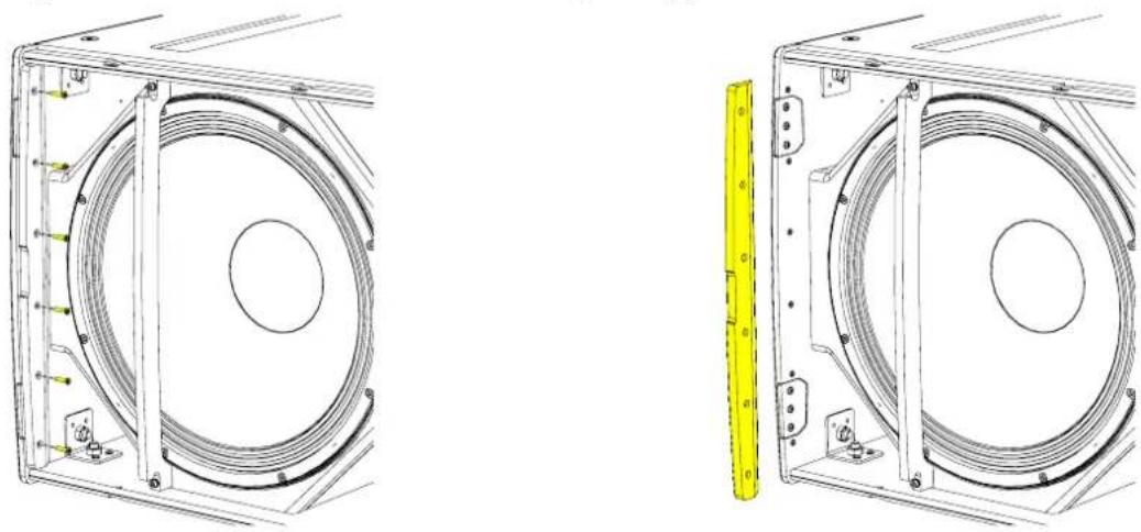
natural_image
Technical line drawings of two mechanical components with circular cutouts and mounting brackets (no text or symbols)Remove the three screws from the bracket.
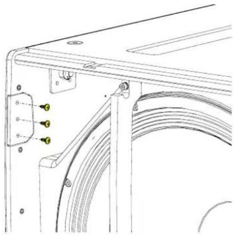
natural_image
Technical line drawing of a mechanical assembly with no visible text or symbolsRotate the bracket 180°. The bracket will now extend approximately 20mm from the front edge of the cabinet, ensure that the slope on the bracket follows the curved contour of the cabinet.

natural_image
Technical line drawing of a mechanical bracket with a yellow directional arrow indicating rotation (no text or symbols)Screw the bracket back in place and repeat for the other three brackets.
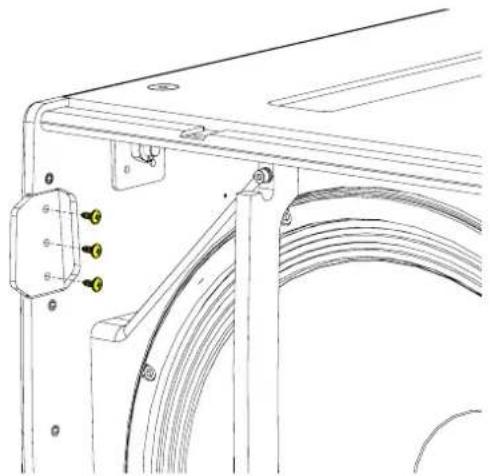
natural_image
Technical line drawing of a mechanical bracket with attached cable and mounting holes (no text or symbols)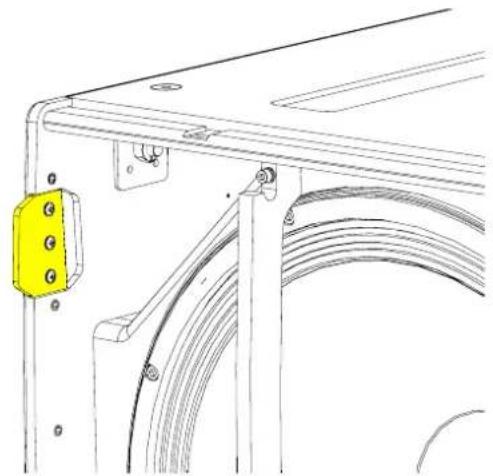
natural_image
Technical line drawing of a mechanical bracket with a yellow safety clip attached (no text or symbols)Replace the grill supports and fit the grille making sure the safety screws are replaced.
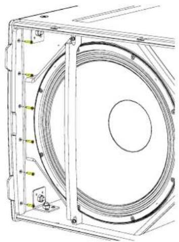
natural_image
Technical line drawing of a mechanical component with concentric circular features and mounting holes (no text or symbols)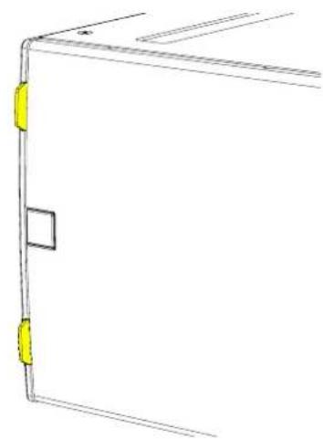
natural_image
Pure technical line drawing of a door or panel corner with yellow connectors (no text or symbols)Castors
To fit the castors, remove the M8 counter-sunk screws from the rear of the enclosure.

natural_image
Technical line drawing of a rectangular electronic device with mounting holes and internal components (no text or symbols)Position each castor over the insets and screw into place using the fixings supplied in the kit.
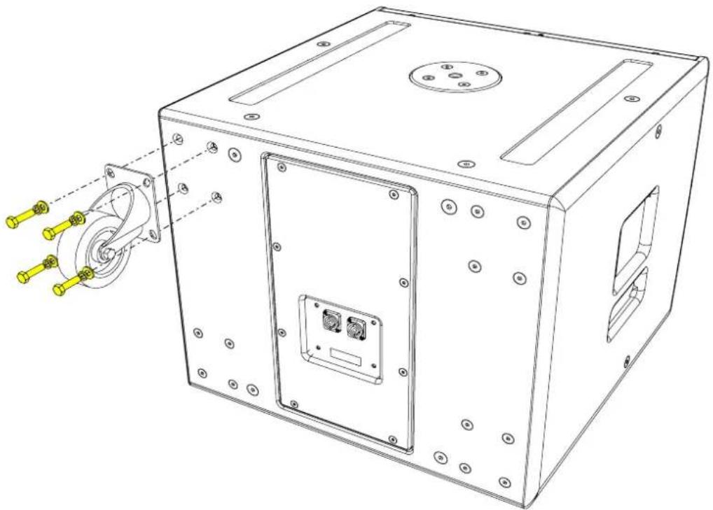
natural_image
Technical line drawing of a mechanical device with mounting holes and internal components (no text or symbols)Weather Kit
The SXP118 has an optional rain cowl available which fixes to the back of the cabinet to protect the amplifier module from inclement weather when used outdoors. This must be factory fitted so should be ordered at the time of purchase or returned to Martin Audio or a Martin Audio approved service agent.
Specifications
TYPE Compact, direct radiating powered subwoofer
FREQUENCY RESPONSE (1) 47Hz-150Hz ± 3dB, -10dB @ 41Hz
DRIVER 18" (460mm)/4" (100mm) voice coil, long excursion, ferrite magnet, waterproof cone
INPUT SENSITIVITY -20dBu for 100dB SPL (CDD-LIVE12/15 pre-set)
-13dBu for 100dB SPL (CDD-LIVE8 pre-set)
MAXIMUM SPL (4) 132dB continuous / 135dB peak
DISPERSION Omnidirectional / Cardioid (paired using cardioid preset)
CROSSOVER Active. Presets for CDD-LIVE 8, 12 & 15 mono-pole or cardioid (paired)
CONNECTORS Female XLR input, male XLR link output, Dante Audio Neutrik® Ethercon
ANALOGUE INPUT IMPEDANCE 20 kΩ balanced to ground
MAXIMUM ANALOGUE INPUT LEVEL 24.6 Vpp (+21dBu), over voltage protected
INTERNAL PROCESSING Multi-channel DSP, programmable via TCP/IP using VU-Net software
PEQ/shelving filters, Up to 48dB/Oct LPF, Up to 200ms input delay
Pre-set selection via rear panel switch
NETWORK CONNECTORS 2xNeutrik® Ethercon
NEWORK PROTOCOL TCP/IP and UDP/IP
AMPLIFIER MODULE 2 channel switch-mode, class D, Bridged Tied
OUTPUT POWER 2000W (Peak), 1000W (Continuous)
AVERAGE EFFICIENCY 89%
COOLING External fan
MAXIMUM AMBIENT TEMPERATURE 40°C (104°F) for full output
POWER SUPPLY Switch mode, fixed frequency with PFC
AC INPUT OPERATING RANGE 85 - 265V \~ AC, 50 - 60Hz
POWER FACTOR > 0.98
ENCLOSURE Extensively braced multi-laminate birch plywoodD
FINISH Textured black PU Coating
PROTECTIVE GRILLE Black perforated Zintec
FITTINGS Two skids on base, matching channels on top. 2 x bar handles
20 top-mounted thread plate for pole mounting
16 x M10 mounting points, 4 x fittings for optional transit cover
IP RATING IP24 factory option available
DIMENSIONS (INCL SKIDS) (W) 600mm x (H) 509mm x (D) 632mm (760mm including castors)
(W) 23.62in x (H) 20.04in x (D) 24.86in (29.9in including castors)
WEIGHT 46.5kg (103lbs). 50Kg (110lbs) with castors
Notes
(1) Measured on-axis in half (2pi) space at 2 metres, then referred to 1 metre.
(2) AES Standard ANSI S4.26-1984.
(3) Measured in half (2pi) space at 2 metres with 1 watt input, using band limited pink noise, then referred to 1 metre.
(4) Measured in half (2pi) space at 2 metres using band limited pink noise, then referred to 1 metre.
(5) Measured on-axis in open (4pi) space at 2 metres, then referred to 1 metre.
(6) Measured in open (4pi) space at 2 metres with 1 watt input, using band limited pink noise, then referred to 1 metre.
(7) Measured in open (4pi) space at 2 metres using band limited pink noise, then referred to 1 metre.
(8) Measured in open (4pi) space at 2 metres with 2.83V input, using band limited pink noise, then referred to 1 metre.
(9) Calculated at 1 metre.
(10) Measured in half (2pi) space at 2 metres with 2.83V input, using band limited pink noise, then referred to 1 metre.
Technical Drawing
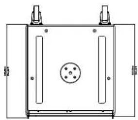
natural_image
Technical line drawing of a rectangular enclosure with internal components and mounting feet (no text or symbols)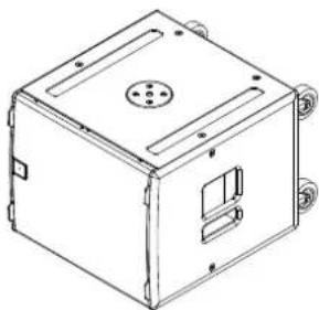
natural_image
Line drawing of a 3D box with mounting holes and internal compartments (no text or symbols)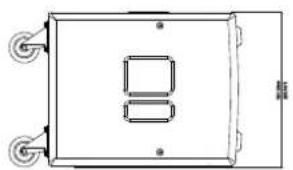
natural_image
Technical line drawing of a rectangular electronic device with two wheels and a 8-pin display (no text or symbols)
natural_image
Simple line drawing of a rectangular frame with a small square cutout on the left side (no text or symbols)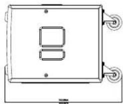
natural_image
Simple line drawing of a rectangular device with two internal components and three wheels (no text or symbols)

natural_image
Technical line drawing of a rectangular frame with two vertical supports and wheels (no text or symbols)Castors are shown for illustration only and are not included as standard.
SXP218
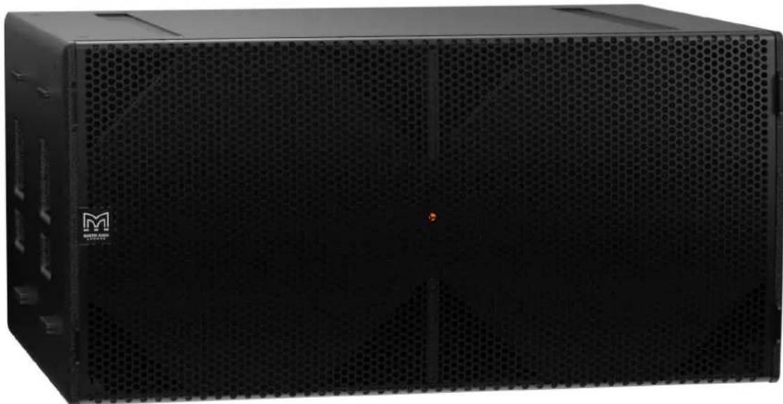
natural_image
Exterior view of a black server rack unit with perforated ventilation grille (no visible text or symbols)Introduction
The SXP218 achieves the ultimate in subwoofer performance for the most demanding professional applications – delivering very high output levels and superb transient performance with minimal distortion. With an operating range of 35Hz-150Hz ± 3dB, it houses dual 18" long-excursion (460mm)/4" (100mm) voice coil drivers with water-resistant cones and triple roll surrounds. The design of the 18" drivers maximises output while minimising power compression and distortion, and the eight reflex ports have a large frontal area to reduce turbulent air noise at very high levels. With a prodigious maximum SPL capability of 143dB peak at 1 metre, the SXP218 is the ideal subwoofer for touring sound reinforcement, theatre and portable live sound applications — as well as premium installations — that require low frequency augmentation with low distortion at very high output levels.
A self-powered system, the SXP218 incorporates a Class D amplifier, DSP and Dante™ digital audio networking — simplifying set-up, enhancing control and eliminating amplifier racks. The onboard amplifier delivers a total of 4000W peak output to the drivers, and its switched-mode power supply auto-ranges to global mains voltages from 100 to 240V 50/60Hz. DSP functions — including parametric EQ, delay, muting, gain and preset selection — can be controlled over Ethernet from a PC or Windows® tablet via intuitive VU-NET™ proprietary software.
Accessories
M10 eyebolts HTKCT06
Install flying frame SX218GRIDi
Flying kit SX218FKIT
Transit cover SXTC218
Castor kit WHEELKIT
Wind-up pole ASF20071
Weather kit CDDLRK118/218
Connections
The SXP218 is a powered subwoofer and shares its connections with the CDD-LIVE range. There are three types of connection on each sub, consisting of mains, analogue XLR and Network Ethercon.

text_image
MAINS CAUTIONAL ADDI NEW OF ELECTRIC INCHES ON SET POWER POWER: 100V AC/DC 500W PRESER: 240V AC/DC 500W PRET. 1 2 3 4 100V AC/DC 500W PRESET INPUT LINK 1 ETHERNET 2 Nemko FC CE SXPMains
The mains inlet is a Neutrik® PowerCon True1 socket and a mating connector is supplied with each CDD-LIVE speaker. The True1 is the latest version of Neutrik's PowerCon range and is a small, light, rugged, inexpensive latching mains connector rated for use up to 240V at 16A. It is rated with a breaking capacity according to IEC60320 and VDE0625 meaning that it can be connected and disconnected without first turning off the power feed. This has the advantage of being very convenient but also makes a power switch unnecessary as it is easy to turn the speaker off by activating the latch and turning the connector anticlockwise which will disconnect the power whilst leaving the plug in place in the socket so it can be quickly rotated clockwise to restore the power connection when required.

text_image
APPLIANCE INLET POWER IN NAC3MPX NAC3FX-W or NKPF (Connector) CABLE EXTENTION NAC3FX-W or NKPF (Connector) NAC3MX-W or NKPM (Plug connector)Wiring Instructions
Wiring instructions for the Neutrik PowerCon True1 are as follows. Note that all mains wiring should be carried out by a competent, trained technician. If a suitable technician is not available Martin Audio would recommend purchasing one of the range of pre-made mains cables available as optional accessories. These feature the PowerCon True1 connector on a flexible cable of either 2.15m (part number ASF12024) or 5m (part number ASF12023) in length and are terminated in a 16A male Ceform connector. Both cables are rated to IP67.
| Approval based: VDE | EN 60320 | ULUL 498 / C22.2 No. 182.3 |
| Rating: 250 V ac / 16A 250 V ac / 20 A | ||
| Cable Type: H05VV-F3G 1.0mm2, Length max. 2mH05VV-F3G 1.5 – 2.5mm2H07RN-F3G 1.5mm2 | SJTOW, SJ00W 3 x 12 AWG | |
| Strain Relief: White Chuck White Chuck | ||
| Cable O.D.: 6.0 – 12.0 mm 6.0 – 12.0 mm | ||
| A: Prepare cable as shown. | 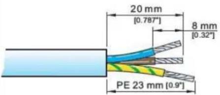 |  |
| B: Place chuck over cable. | | |
| C: Wire the connectorUsing a Torx T8 driver, the fixing screws should be tightened to a torque value of 0.7Nm. | | |
| LiveNeutralGround | BrownBlueGreen/yellow | BlackWhiteGreen |
| D: Assemble the connectorSlide the chuck onto insert and then both into the housing.Note: Align the chuck by positioning the nose into the keyway. | | ||
| E: Tighten the cable clampSlide the cable clamp up the cable and tighten. To wire the connector to IP65, the cable clamp needs to be tightened to a torque value of 2.0Nm using the Neutrik tool no. HTAC with a 13mm spanner. | | ||
| DisassemblyPress a small flat-blade screwdriver into the cable clamp bush by the ☐ symbol, continue to push the screwdriver in whilst unscrewing the clamp. | |
Analogue Audio
Analogue audio is available on a 3-pin XLR socket with a parallel male XLR socket to enable easy "daisy-chain" wiring looping from one speaker to the next. Analogue inputs should be connected with a good quality 3-pin male XLR wired to good quality twin screened cable. This is particularly important if the input cable run is long (e.g., from the FOH position to stage). Good quality cable will minimise losses. The link outputs should use a similarly high quality female XLR. The line driver at the signal source must be able to drive the combined load of all SXP subwoofers or CDD-LIVE being linked. Wiring is the industry standard for balanced connections:
| PIN CONNECTION |
| 1 Ground or shield |
| 2 Signal 'hot' ('+') |
| 3 Signal 'cold' ('-') |
Network
Two network ports are available to control the subwoofer via Martin Audio's VU-NET software and to route Dante audio to each sub. The two Ethernet ports are available on Neutrik Ethercon connectors which can be used either with a compatible mating connector or directly with a CAT5 cable with RJ45 connectors. The connections are routed to a two-port switch which enables daisy-chain Ethernet/Dante connections of up to 8 cabinets. Alternatively, a star network configuration can be adopted using any Gigabit enabled Ethernet router connecting individual Ethernet cables to each cabinet. Note that the ports can carry both Dante and TCP/IP data simultaneously so a Dante network can be set up with control over all CDD-LIVE cabinets via VU-NET.
Note that you must use a network system that supports DHCP to connect multiple CDD-LIVE products, a simple Ethernet switch will NOT work unless the entire system is configured for static IP, you will need an Ethernet router or a device connected to an Ethernet switch which will support DHCP to assign IP addresses to all devices on the network. You can connect directly from a PC Ethernet port to ONE CDD-LIVE cabinet which will self-assign an IP address in the same range as the PC. This takes around one minute and after that it will be possible to connect to the cabinet via VU-NET. You CANNOT daisy-chain more CDD-LIVE cabinets in this configuration. It can only be used with a single cabinet so its use is limited to simple checks or firmware updates.
Dante is realised using the Ultimo board, this does not support primary and secondary connections but redundancy is possible using an analogue audio feed simultaneously with a Dante network. The input will automatically select Dante is a signal is present however it will automatically switch to the analogue feed if the Dante signal is lost. The Ethernet ports have standard LED indicators to show operation. The green LEDs show that the port is operational and should illuminate as soon as a connection is made to or from an Ethernet port from any other port. The yellow LEDs flash to show data speed. The Dante LED will illuminate when a Dante feed is present.
Preset Operation
SXP218 can be fully configured using VU-NET on an Ethernet network. Alternatively plug-and-play operation is available using factory presets selected using the preset button on the connector panel.

text_image
MATERIALS INPUT LINK 10V-240Hz 30.0MHz Nemko SXP 1 2 3 4 PRESET @Danta® 1 ETHERNET 2 CE SXPPreset 1 - SXP218 used in conjunction with CDD-LIVE12 or CDD-LIVE15:

text_image
1 2 3 4Preset 2 - SXP218 used in conjunction with CDD-LIVE8:

text_image
1 2 3 4Preset 3 - SXP218 used in conjunction with CDD-LIVE12 or CDD-LIVE15 in cardioid (rear facing) mode:

text_image
1 2 3 4Preset 4 - SXP218 used in conjunction with CDD-LIVE8 in cardioid (rear facing) mode:

text_image
1 2 3 4Note that the selected preset is retained after powering down the SXP218. The same preset will still be selected when you next power-up the cabinet.
When a system is connected to VU-NET via the Ethernet ports the preset LEDs will be extinguished to show that the system settings may have been changed. To restore the preset once VU-NET is disconnected press the preset button until it has cycled round to the preset you require. Any changes made in VU-NET will then be overwritten with the factory setting.
Meter Mode
An additional feature is meter mode which is selected by pressing and holding the preset select button for two seconds. In this mode the LEDs which normally indicate which preset has been selected, become an input level bar graph to show level applied to the speaker. To return to normal preset selection, press and hold again for two seconds.
Dante
SXP218 can be fed via a Dante feed on an Ethernet network. Hundreds of Dante-enabled products are available, enabling you to mix devices from multiple manufacturers.
Dante does away with heavy, expensive analogue or multicore cabling, replacing it with low-cost, easily-available CAT5e, CAT6, or fibre optic cable for a simple, lightweight and economical solution. Dante integrates media and control for your entire system over a single, standard IP network.
Dante systems can easily scale from a simple pairing of a console to a computer, to large capacity networks running thousands of audio channels. Because Dante uses logical routes instead of physical point-to-point connections, the network can be expanded and reconfigured at any time with just a few mouse clicks.
Since audio is transmitted digitally, you don't have to worry about the common analogue challenges of interference from other electrical equipment, crosstalk between cables, or signal degradation over long cable runs.
Signal routing and system configuration with Dante Controller can be fast, simple. Setting up a Dante network is typically just a matter of plugging devices into an Ethernet switch and connecting a computer to the network. All Dante devices are automatically discovered and displayed in Dante Controller
With Dante Controller you can easily edit device names and channel labels, control sample rates, and set device latencies. Once the network is configured, the computer running Dante Controller can be removed from the network, and reconnected only if changes are required or system monitoring is desired. Signal routing and other system settings are stored safely in the Dante devices themselves, so they are automatically restored if a device is power-cycled.
Real-time information about the health of your network is essential for a proper understanding of its performance. Audinate's diagnostic tools provide visibility into the network health status through features such as device latency monitoring, active clock health monitoring, packet error reporting and bandwidth usage statistics.
VU-NET
SXP218 may be controlled using Martin Audio's VU-NET software application. VU-NET is Martin Audio's proprietary application for control of monitoring of network controlled powered products. Introduced as the control platform for MLA, MLA Compact and MLA Mini, a number of products have been added to Martin Audio's portfolio that can be incorporated into a single project and configured using VU-NET. SXP218 subwoofers in combination with the CDD-LIVE Series are fully integrated into the platform.
For further information and instruction on VU-NET and to download the application and user guide, please visit www.martin-audio.com/software.
Flying SXP218
Eyebolts
The SXP218 features M10 inserts to allow flown applications using eyebolts. M10 eyebolts suitable for flown systems are available as accessories from Martin Audio. These are cast steel shouldered eye bolts specifically designed and rated for flown applications. If alternative eyebolts are used these must be cast or machined products stamped with their SWL. Formed steel non-shouldered eyebolts commonly available from DIY stores should not be used under any circumstances as they are not sufficiently load-rated for flown applications.
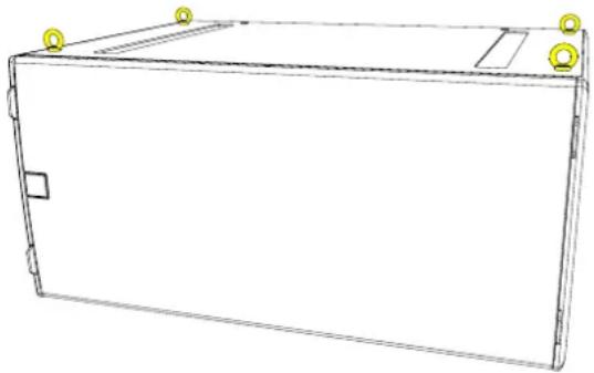
natural_image
Line drawing of a rectangular electronic device with mounting holes and a side panel (no text or symbols)Remove the M10 counter-sunk screws and screw the eyebolts into position. We would recommend four eyebolts and an additional eyebolt as a redundant safety bond. This should be attached to a different point than the other bolts to support the cabinet in the event of the other points failing.
Eyebolts should be connected to a suitably rated fixing point such as a girder clamp or a heavy duty fixing such as a sleeve anchor or similar. They can be linked using suitably rated steel rope or chain and shackles.
Safety note: Flying heavy equipment in public spaces is dangerous and should only be undertaken by suitably qualified and experienced personnel using adequately rated equipment for the task.
Flying Frame and Flying Kit
A flying system is available for the SXP218 for installation applications. This uses the SX218FKIT and SX218GRIDi.

natural_image
Line drawing of a rectangular electronic device casing with mounting brackets and ventilation slots (no text or symbols)Fit the SX218FKIT flying kit to each cabinet. There are four steel brackets in each kit and these attach vertically, two on each side of the subwoofer. Remove all four M10 bolts in the inserts on the sides of the cabinet.

text_image
Technical diagram of a multi-chamber electronic device with labeled components and mounting pointsAttach the brackets, two on each with the "dog-leg" in the bracket at the top angled outwards using two M10 bolts and washers in each bracket.
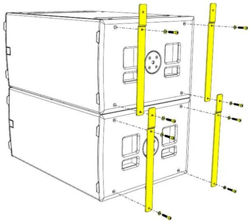
natural_image
Technical line drawing of a multi-chamber air vent system with yellow connectors and mounting holes (no text or labels)
natural_image
Technical line drawing of a two-tiered modular device with yellow vertical connectors and mounting holes (no text or symbols)Next the SX218GRIDi should be attached to the two chain hoists that are being used to suspend the sub array. One point is required at the front and a second at the back. The hooks on the hoists can be attached using the two 3.25T Shackles supplied with the grid. Fly the grid out to a height so you can move the SXP218 under it then lower the grid to line up the fixing holes on the grid with those on the brackets on the sub.

natural_image
Technical line drawing of a multi-tiered industrial enclosure with mounting brackets and internal compartments (no text or symbols)Join using the four M10 x 50 button head screws and washers supplied with the grid assembly. The sub can now be safely flow to the desired height.
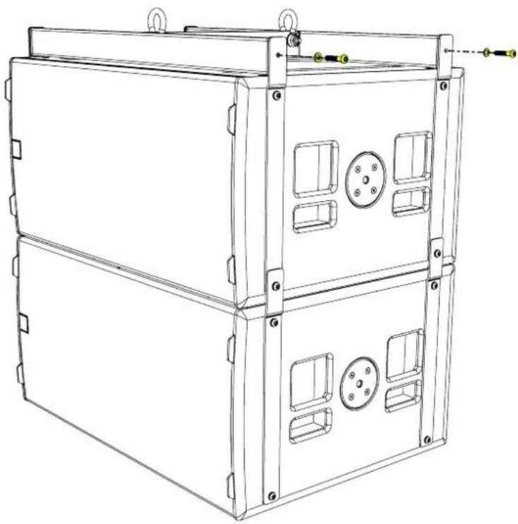
natural_image
Technical line drawing of a multi-tiered industrial enclosure or storage unit with mounting holes and control panels (no text or symbols)A maximum of six SXP218 subwoofers can be flown using this method.
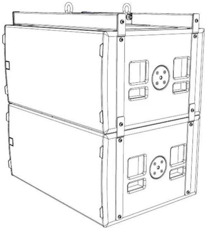
natural_image
Technical line drawing of a multi-tiered rectangular electronic device with mounting brackets and internal compartments (no text or symbols)Transit Covers
The SXP218 features an optional transit cover to protect the cabinet when used in portable applications.
To ensure that the insert is accurately located, four locating brackets are utilised. These are built into the cabinet in the four corners and maybe fitted in the parked position as standard. To use with the transit cover it is necessary to reverse the four brackets.
Remove the top and bottom safety screws from the grille. Insert a flat blade screwdriver into the slots of the grille and carefully easing the grille out of the slot.

natural_image
Line drawing of a rectangular electronic device casing with internal compartments and mounting holes (no text or symbols)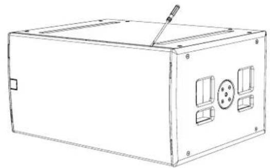
natural_image
Line drawing of a rectangular electronic device with internal compartments and a handle (no text or symbols)Remove the Grille and screws from the side of the cabinet and remove the grille support.

natural_image
Technical line drawing of an industrial enclosure with internal components and a fan-like structure (no text or symbols)
natural_image
Technical line drawing of a mechanical assembly with concentric circular components and mounting brackets (no text or symbols)Remove grille support
Remove the three screws from the bracket.

natural_image
Technical line drawing of a mechanical assembly with circular components and mounting brackets (no text or symbols)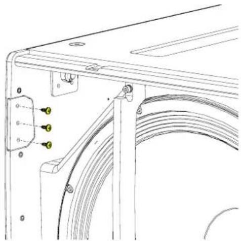
natural_image
Technical line drawing of a mechanical assembly with labeled components (no text or symbols)Rotate the bracket 180°. The bracket will now extend approximately 20mm from the front edge of the cabinet, ensure that the slope on the bracket follows the curved contour of the cabinet.

natural_image
Technical line drawing of a mechanical bracket with a yellow directional arrow indicating rotation (no text or symbols)Screw the bracket back in place and repeat for the other three brackets.

natural_image
Technical line drawing of a mechanical assembly with mounting brackets and a curved internal component (no text or symbols)
natural_image
Technical line drawing of a mechanical bracket with a yellow safety clip attached (no text or symbols)Replace the grill supports and fit the grille making sure the safety screws are replaced

natural_image
Technical line drawing of a mechanical assembly with concentric circular components and mounting brackets (no text or symbols)
natural_image
Line drawing of a rectangular electronic device casing with mounting holes and internal compartments (no text or symbols)Castors
To fit the castors, remove the M8 counter-sunk screws from the rear of the enclosure.

natural_image
Technical line drawing of a rectangular electronic device with mounting holes and internal components (no text or symbols)Position each castor over the insets and screw into place using the fixings supplied in the kit.

natural_image
Technical line drawing of a rectangular electronic device with mounting holes and internal components (no text or symbols)Weather Kit
The SXP218 has an optional rain cowl available which fixes to the back of the cabinet to protect the amplifier module from inclement weather when used outdoors. This must be factory fitted so should be ordered at the time of purchase or returned to Martin Audio or a Martin Audio approved service agent.
Specifications
TYPE Dual-driver, direct radiating powered subwoofer
FREQUENCY RESPONSE (1) 35Hz-150Hz ± 3dB, -10dB @ 30Hz
DRIVER 2 x 18" (460mm)/4" (100mm) voice coil, long excursion, ferrite magnet, waterproof cone
INPUT SENSITIVITY -20dBu for 100dB SPL (CDD-LIVE12/15 pre-set),
-13dBu for 100dB SPL (CDD-LIVE8 pre-set)
MAXIMUM SPL (4) 140dB continuous / 143dB peak
DISPERSION Omnidirectional / Cardioid (paired using cardioid preset)
CROSSOVER Active. Presets for CDD-LIVE 8, 12 & 15 mono-pole or cardioid (paired)
CONNECTORS Female XLR input, male XLR link output, Dante Audio Neutrik® Ethercon
ANALOGUE INPUT IMPEDANCE 20 kΩ balanced to ground
MAXIMUM ANALOGUE INPUT LEVEL 24.6 Vpp (+21dBu), over voltage protected
INTERNAL PROCESSING Multi-channel DSP, programmable via TCP/IP using VU-Net software
PEQ/shelving filters, Up to 48dB/Oct LPF, Up to 200ms input delay
Pre-set selection via rear panel switch
NETWORK CONNECTORS 2xNeutrik® Ethercon
NEWORK PROTOCOL TCP/IP and UDP/IP
AMPLIFIER MODULE 2 channel switch-mode, class D, Bridged Tied Load
OUTPUT POWER 4000W (Peak), 2000W (Continuous)
AVERAGE EFFICIENCY 89%
COOLING External fan
MAXIMUM AMBIENT TEMPERATURE 40°C (104°F) for full output
POWER SUPPLY Switch mode, fixed frequency with PFC
AC INPUT OPERATING RANGE 85 - 265V \~ AC, 50 - 60Hz
POWER FACTOR > 0.98
ENCLOSURE Extensively braced multi-laminate birch plywood
FINISH Textured black PU Coating
PROTECTIVE GRILLE Black perforated Zintec
FITTINGS Two skids on base, matching channels on top. 2 x bar handles.
M20 top-mounted thread plate for pole mounting
24 x M10 mounting points, 4 x fittings for optional transit cover
IP RATING IP24 factory option available
DIMENSIONS (INCL SKIDS) (W) 1085mm x (H) 537mm x (D) 792mm (920mm including castors)
(W) 42.72in x (H) 21.13in x (D) 31.16in (36.2in including castors)
WEIGHT 101.5kg (224lbs). 105Kg (231lbs) with castors
Notes
(1) Measured on-axis in half (2pi) space at 2 metres, then referred to 1 metre.
(2) AES Standard ANSI S4.26-1984.
(3) Measured in half (2pi) space at 2 metres with 1 watt input, using band limited pink noise, then referred to 1 metre.
(4) Measured in half (2pi) space at 2 metres using band limited pink noise, then referred to 1 metre.
(5) Measured on-axis in open (4pi) space at 2 metres, then referred to 1 metre.
(6) Measured in open (4pi) space at 2 metres with 1 watt input, using band limited pink noise, then referred to 1 metre.
(7) Measured in open (4pi) space at 2 metres using band limited pink noise, then referred to 1 metre.
(8) Measured in open (4pi) space at 2 metres with 2.83V input, using band limited pink noise, then referred to 1 metre.
(9) Calculated at 1 metre.
(10) Measured in half (2pi) space at 2 metres with 2.83V input, using band limited pink noise, then referred to 1 metre.
Technical Drawing
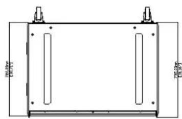
natural_image
Technical line drawing of a rectangular frame with vertical supports and dimension lines (no text or symbols)
natural_image
Line drawing of a rectangular electronic device casing with ports and buttons (no text or symbols)

natural_image
Simple line drawing of a rectangular frame with a small square cutout and dimension labels (no text or symbols beyond measurement markers)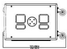
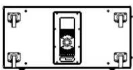
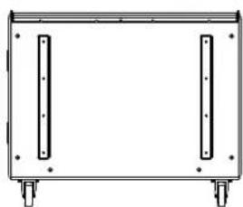
natural_image
Simple line drawing of a rectangular frame with two vertical supports and four corner legs (no text or symbols)Castors are shown for illustration only and are not included as standard.
Warranty
SX110, SX210, SX112, SX212, SXF115, SXC118, SX118, SXC118, SXCF118, SX218, SXH218, SXHF218
Martin Audio SX subwoofers are warranted against manufacturing defects in materials or craftsmanship over a period of 5 years from the date of original purchase.
During the warranty period Martin Audio will, at its discretion, either repair or replace products which prove to be defective provided that the product is returned in its original packaging, shipping prepaid, to an authorised Martin Audio service agent or distributor.
Martin Audio cannot be held responsible for defects caused by unauthorised modifications, improper use, negligence, exposure to inclement weather conditions, act of God or accident, or any use of this product that is not in accordance with the instructions provided by Martin Audio.
Martin Audio is not liable for consequential damages.
This warranty is exclusive and no other warranty is expressed or implied. This warranty does not affect your statutory rights.
SXP118, SXP218
Martin Audio SXP subwoofers are warranted against manufacturing defects in materials or craftsmanship over a period of 5 years from the date of original purchase.
Martin Audio SXP amplifier modules are warranted against manufacturing defects in materials or craftsmanship over a period of 2 years from the date of original purchase.
During the warranty period Martin Audio will, at its discretion, either repair or replace products which prove to be defective provided that the product is returned in its original packaging, shipping prepaid, to an authorised Martin Audio service agent or distributor.
Martin Audio cannot be held responsible for defects caused by unauthorised modifications, improper use, negligence, exposure to inclement weather conditions, act of God or accident, or any use of this product that is not in accordance with the instructions provided by Martin Audio.
Martin Audio is not liable for consequential damages.
This warranty is exclusive and no other warranty is expressed or implied. This warranty does not affect your statutory rights.
Martin Audio Limited
Century Point
Halifax Road
Cressex Business Park
FOR SALES ENQUIRIES:
High Wycombe
Buckinghamshire
HP12 3SL
England
UK
Telephone: +44 (0)1494 535312
E-mail: info@martin-audio.com
NORTH AMERICA
Telephone: 323-381-5310
www.martin-audio.com
All information is Copyright © 2023 Martin Audio Ltd.
Martin Audio, the Martin Audio logo and Hybrid are registered trademarks of Martin Audio Ltd. in the United Kingdom, United States and other countries; all other Martin Audio trademarks are the property of Martin Audio Ltd.