Adorn A40T - Speaker Martin Audio - Free user manual and instructions
Find the device manual for free Adorn A40T Martin Audio in PDF.

User questions about Adorn A40T Martin Audio
0 question about this device. Answer the ones you know or ask your own.
Ask a new question about this device
Download the instructions for your Speaker in PDF format for free! Find your manual Adorn A40T - Martin Audio and take your electronic device back in hand. On this page are published all the documents necessary for the use of your device. Adorn A40T by Martin Audio.
USER MANUAL Adorn A40T Martin Audio
natural_image
Product display of white and black audio equipment including speakers, lenses, and a speaker tower (no visible text or symbols)ADORN
Contents
ADORN On-wall Introduction
ADORN On-wall 4
Aesthetics 4
Options 4
Protection 4
Unpacking the Unit 4
ADORN On-wall Overview
A40/A40T 5
A55/A55T 5
Accessories 6
ADORN On-wall System Requirements
Low Impedance Systems 7
70v and 100v Line Systems 7
Connections 7
ADORN On-wall Deployment
Wall-mounting 8
Ceiling-mounting 9
ADORN Ceiling Introduction
ADORN Ceiling 11
Aesthetics and Model Numbers 11
Options 11
Protection 11
Unpacking the Unit 11
ADORN Ceiling Overview
ACS-40TS 12
ACS-55TS 12
ACS-55T....12
ACP-55T 12
Accessories 13
ADORN Ceiling System Requirements
Low Impedance Systems 14
70v and 100v Line Systems 14
Connections 14
ADORN Ceiling Deployment
Hole Cut-outs.15
Suspended Ceilings 15
ADORN Pendant Deployment
ACP-55T 18
Technical Specifications
A40/A40T 19
A55/A55T 19
ACS-40TS 20
ACS-55TS 20
ACS-55T 20
ACP-55T 21
Technical Drawings
A40 22
A40T 23
A55 24
A55T 25
ACS-40TS 26
ACS-55TS 27
ACS-55T 28
ACP-55T 29
Warranty
Warranty Statement 30
ADORN On-wall Introduction
ADORN On-wall
Thank you for purchasing a Martin Audio ADORN series system. ADORN was launched to meet the demand for ultra-compact, discreet, easy to deploy speaker for a wide range of commercial integration projects, meeting the price point often demanded whilst still delivering superior sound quality and the signature Martin Audio tonal characteristics. ADORN is an ideal partner to larger Martin Audio systems in venues that may have a wide variety of zones, to provide a seamless transition and retaining the same sonic performance and tonal quality.
Aesthetics
The ADORN on-wall series have been designed to be as visually unobtrusive with bezel-free grilles for a clean look. All models are available in black (RAL 9005) and white (RAL 9016).
Options
The A40T and A55T are fitted with a 70v and 100v line transformers to select the appropriate output power. There is also a low impedance mode on all models (16Ω), enabling up to 8 speakers to be driven by a single amplifier channel with 2Ω load capability.
Protection
All models have built-in independent protection for the high and low frequency drivers to ensure reliable operation in the event of an overload condition.
Unpacking the Unit
Every Martin Audio loudspeaker is built to the highest standard and thoroughly inspected before it leaves the factory. After unpacking the system, examine it carefully for any signs of transit damage and inform your dealer if any is found. It is suggested that you keep the original packaging so that the system can be repacked at a future date if necessary.
When the product has reached the end of its useful life, please dispose of it responsibly through a recycling centre.
ADORN On-wall Overview

natural_image
Black studio microphone with perforated grille and logo (no visible text or symbols)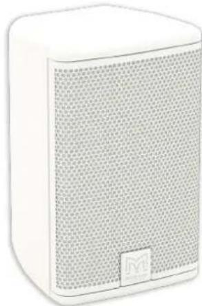
natural_image
White rectangular electronic device with a mesh grille and a small logo on the front panel (no visible text or symbols)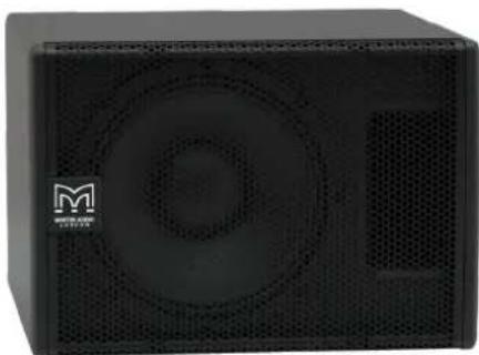
natural_image
Black rectangular electronic device with speaker grille and ventilation grille (no visible text or symbols)A40/A40T
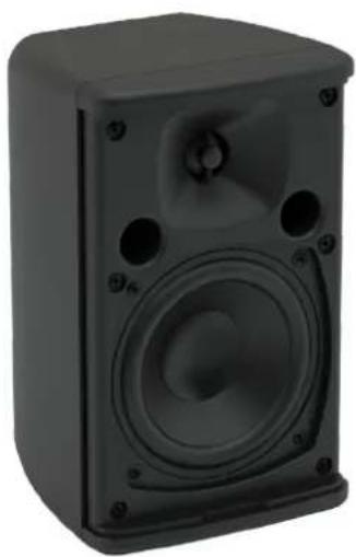
The A40 is a two-way passive speaker with an elegant design that is perfect for architectural interiors that require high-fidelity sound from an unobtrusive, ultra-compact enclosure. Comprising a 4" (100mm) LF driver and a 0.75" (19mm) silk-dome HF driver on a 110° x 80° horn, it handles 40W AES, 160W peak and can produce 109dB peak output at 1 metre.
It is available as standard in either black or white and its paintable ABS enclosure can be wall-mounted vertically or horizontally using the mounting bracket supplied. With a nominal impedance of 16 ohms, multiple speakers can be driven in parallel from a single channel of a low impedance amplifier such as the Martin Audio VIA2004.
The A40T transformer option features a built-in 70vV/100v multi-tap transformer for line operation.
The enclosure is suitable for outdoor usage when used with the waterproof connector cover accessory (sold separately).
A55/A55T
The A55 features a 5.25" (135mm) LF driver and a 0.75" (19mm) silk-dome HF driver on a 110° x 80° horn. With a power handling of 50W AES, 200W peak, and a maximum SPL of 113dB at 1 metre, it is designed for background and foreground applications that call for premium sound quality and high levels from a visually discreet enclosure.
It is available as standard in either black or white and its paintable ABS enclosure can be wall-mounted vertically or horizontally using the mounting bracket supplied and its nominal impedance of 16 ohms enables multiple speakers to be driven in parallel from a single channel of a low impedance amplifier such as the Martin Audio VIA2004.
A transformer option, the A55T, with a built-in 70vV/100v multi-tap transformer is available for line operation.
The enclosure is suitable for outdoor usage when used with the waterproof connector cover accessory (sold separately).
Subwoofers
For full range music systems, a subwoofer may be added. We would recommend a speaker from the Martin Audio SX Series such as the SX110 which is a very compact single 10" subwoofer. This must be driven by another amplifier, for small low impedance systems the four channel VIA2504 or VIA5004 amplifiers are recommended. A system controller will be required to act as a crossover between the subwoofer and ADORN speakers. The DX0.5 or DX4.0 are recommended processors.
Accessories
AIPKIT - Weatherised connector cover
The cover is fitted to the rear of any of the wall-mount systems. It allows cable entry via a sealed gland to provide a weather resistant connection to enable the speakers to be used outdoors. Available in black (AIPKIT) and white (AIPKIT-W). Suitable for use with all ADORN on-wall models. Sold separately.

natural_image
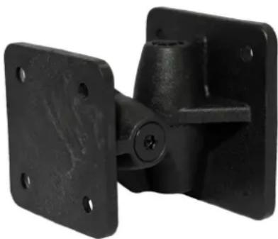
Black plastic mechanical bracket with two circular holes and a square base (no text or symbols)ASM10002 / ASM10001 - Wall bracket
Allows wall-mounting of all ADORN models, featuring vertical and horizontal tilt and pan. Weatherised for outdoor installation. Available in black (ASM10002) and white (ASM10001). Suitable for use with all ADORN on-wall models. Supplied with product.
natural_image
Close-up of a black metal bracket with mounting flanges and bolt holes (no text or symbols visible)CDDCB5 - Ceiling bracket
Allows ceiling-mounting of all ADORN models, featuring vertical tilt. Weatherised for outdoor installation. Available in black (CDDCB5B-WR), white (CDDCB5W-WR) and custom RAL colours. Suitable for use with all ADORN on-wall models. Sold separately.

natural_image
3D rendering of a black metal bracket with mounting holes (no text or symbols)ADORN On-wall System Requirements
Low Impedance Systems
The ADORN A40 and A55 are designed to be used in a low impedance system.
The selector switch is located on the rear of the speaker on wall-mount models A40T and A55T and is on the baffle behind the grill on the ceiling and pendant products. A conventional power amplifier or mixer-amplifier designed for use with low impedance loads must be used. We recommend an amplifier that can deliver the full peak power rating without risk of clipping to ensure the best possible performance and to avoid damage. The Martin Audio VIA amplifier range are a good match for the ADORN series. Performance can be further maintained by using a good quality system processor to introduce a system protection limiter. The Martin Audio DX0.5 is recommended for use with the ADORN series.
70v and 100v Line Systems
An amplifier designed for driving distributed line system must be used. The appropriate tap must be selected using the rotary switch, located on the back of A40T and A55T.

text_image
Technical diagram showing a circular component with internal features and a connecting line indicating connection or assembly.Ensure that the sum of all speaker taps does not exceed the amplifier's rated power output.
A40T
70v: 20w / 10w / 5w / 2.5w
100v: 20w / 10w / 5w / n/a
A55T
70v: 30w / 15w / 7.5w / 3.75w
Connections are made to all ADORN on-wall speakers using simple spring-loaded push terminals.
Strip approximately 10mm of insulation from the ends of your speaker cables, twist stranded cable or use crimped bootlace ferrule on the ends. Depress the push lever, insert the cables into the hole and release the lever. Positive, (+) connections should be made to the red terminal, Negative, (-) connections should go to the black terminal. If “daisy-chaining” connections to several speakers, either twist two wires together prior to inserting in the terminal or insert two wires together.
ADORN On-wall Deployment
Wall-mounting
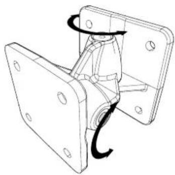
The ADORN on-wall loudspeakers are supplied with a bracket to ensure trouble free installation. The bracket is a three-part design which allows adjustment in both horizontal and vertical planes.
natural_image
Technical line drawing of a mechanical bracket assembly with mounting holes and a curved arrow indicating rotation (no text or symbols)The first stage is to disassemble the bracket so that the cabinet half can be fitted to the speaker and the wall section attached to the wall. A 4mm Allen key is required. If adjustment is only required in one plane, vertical or horizontal, the middle section can be removed. This has the added advantage that the speaker will be closer to the wall.
natural_image
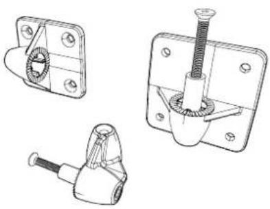
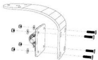
Technical line drawings of three mechanical components: a bracket, a screw with threaded end, and a clamp-like connector (no text or symbols)Fit the wall bracket in the appropriate orientation for horizontal or vertical adjustment. Fixings appropriate for the wall surface and weight of the cabinet must be used to ensure a safe and secure installation.

natural_image
Technical diagram of a mechanical assembly with four bolted pins and a central cylindrical component (no text or labels)Fit the cabinet half of the bracket to the speaker using the four screws in the centre of the rear of the cabinet.
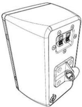
natural_image
Line drawing of a rectangular electronic device with mounting holes and a central connector (no text or symbols)The cabinet can be fitted to the wall by linking the two halves of the bracket using the M4 Allen head bolt.
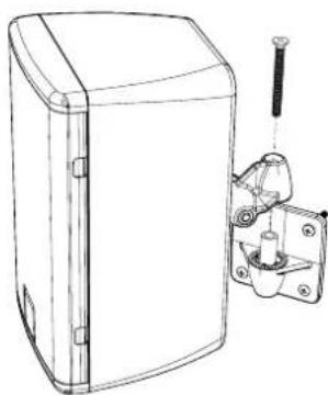
natural_image
Technical line drawing of a device housing with mounting bracket and screw assembly (no text or symbols)Ceiling-mounting
An alternative option is to ceiling mount the ADORN on-wall speakers using the optional ceiling bracket, part number CDDCB5.
Fit the cabinet half of the bracket to the speaker using the four screws in the centre of the rear of the cabinet. For ceiling installation, the bracket must be installed in the orientation below:
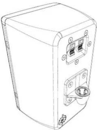
natural_image
Line drawing of a rectangular electronic device with ports and a central connector (no text or symbols)Fit the wall part of the bracket to the ceiling bracket (CDDCB5) with the fastenings supplied.
text_image
Technical diagram of a curved mechanical component with labeled parts and mounting holes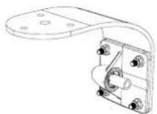
Connect the two assemblies together using the M6 x 60 supplied with we wall bracket. This configuration will give you tilt adjust only.

natural_image
Technical line drawing of a mechanical device with mounting holes and internal components (no text or symbols)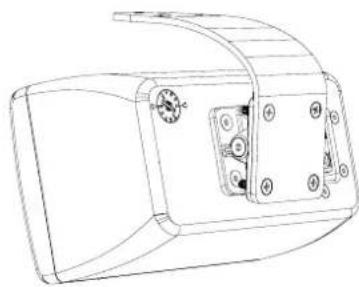
natural_image
Technical line drawing of a mechanical component with mounting holes and a curved housing (no text or symbols)If "pan & tilt" adjustment is needed repeat the above process with the pan and tilt coupler included.

natural_image
Technical line drawing of a mechanical component with cylindrical and ring features (no text or symbols)
natural_image
Line drawing of a device housing with a yellow cartoon character inside, no text or symbols presentADORN Ceiling Introduction
ADORN Ceiling
Thank you for purchasing a Martin Audio ADORN series system. ADORN was launched to meet the demand for ultra-compact, discreet, easy to deploy speaker for a wide range of commercial integration projects, meeting the price point often demanded whilst still delivering superior sound quality and the signature Martin Audio tonal characteristics. ADORN is an ideal partner to larger Martin Audio systems in venues that may have a wide variety of zones, to provide a seamless transition and retaining the same sonic performance and tonal quality.
Aesthetics and Model Numbers
The ADORN ceiling series have been designed to be as visually unobtrusive with bezel-free grilles for a clean look. All in-ceiling models are available in (RAL 9016) white while pendant models are available in (RAL 9005) black and (RAL 9016) white, with the following model reference numbers:
ACS-40TS-W 4" ceiling speaker - white
ACS-55TS-W 5" shallow ceiling speaker - white
ACS-55T-W 5" ceiling speaker - white
ACP-55T-W 5" pendant speaker - white
ACP-55T 5" pendant speaker - black
For simplicity, however, the user guide refers to models generically, not utilising the -W reference to denote white specifically.
Options
All models are fitted with a 70v/100v multi-tap line transformer to select the appropriate output power. There is also a low impedance mode (16Ω, enabling up to 8 speakers to be driven by a single amplifier channel with 2Ω load capability.
Protection
All models have built-in independent protection for the high and low frequency drivers to ensure reliable operation in the event of an overload condition.
Unpacking the Unit
Every Martin Audio loudspeaker is built to the highest standard and thoroughly inspected before it leaves the factory. After unpacking the system, examine it carefully for any signs of transit damage and inform your dealer if any is found. It is suggested that you keep the original packaging so that the system can be repacked at a future date if necessary.
When the product has reached the end of its useful life, please dispose of it responsibly through a recycling centre.
ADORN Ceiling Overview
ACS-40TS
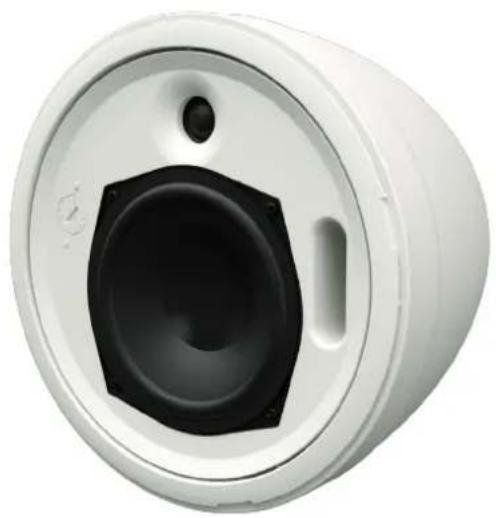
Comprising a 4" (100mm) LF driver and a 0.75" (19mm) silk-dome tweeter, the ACS-4OTS produces 108dB peak output at 1 metre and has a high-fidelity sonic character ideal for both music and speech reproduction. Its ported design delivers strong bass that extends down to 73 Hz.
The very wide 180° conical coverage of the ACS-40TS makes it particularly suitable for low ceilings and reduces the number of speakers required for even coverage — leading to a reduction in installation cost. It features a shallow back can for installation in ceilings with a minimum cavity depth.
ACS-55TS
Comprising a 5.25" (100mm) LF driver and a 0.75" (19mm) silk-dome tweeter, the ACS-55TS produces 113dB peak output at 1 metre and has a high-fidelity sonic character ideal for both music and speech reproduction. Its ported design delivers strong bass that extends down to 79Hz.
The wide 150° conical coverage of the ACS-55TS makes it particularly suitable for low ceilings and reduces the number of speakers required for even coverage — leading to a reduction in installation cost. It features a shallow back can for installation in ceilings with a minimum cavity depth.
ACS-55T
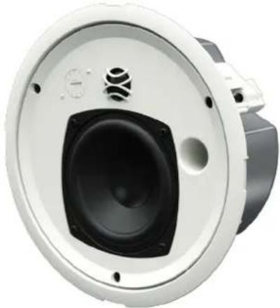
Comprising a 5.25" (100mm) LF driver and a 0.75" (19mm) silk-dome tweeter, the ACS-55T produces 113dB peak output at 1 metre and has a high-fidelity sonic character ideal for both music and speech reproduction. Its ported bass reflex design and back can with generous internal volume maximises low frequency output and delivers strong bass that extends down to 62Hz.
The wide 150° conical coverage of the ACS-55T reduces the number of speakers required for even coverage — leading to a reduction in installation cost.
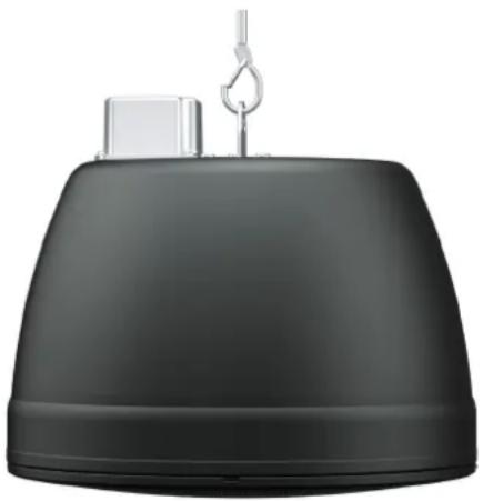
ACP-55T
Comprising a 5.25" (100mm) LF driver and a 0.75" (19mm) silk-dome tweeter, the ACP-55T produces 109dB peak output at 1 metre and delivers superb sound quality for both music and speech reproduction. Its stylish pendant enclosure is equipped with a single-point mounting system plus provision for attaching a safety cable.
The consistent and wide 150° conical coverage of the ACP-55T reduces the number of speakers required for even coverage — leading to a reduction in installation cost.

Accessories
C bracket
Appropriately sized support ring for ACS-40TS, ACS-55TS and ACS-55T. Supplied with product.

natural_image
3D rendered mechanical ring component with curved and straight ends (no text or symbols)Tile rails
Support rails for suspended ceiling. Supplied with product.

natural_image
Two black metal clamps with metallic clips, no text or symbols visibleCK3
3m suspension cable accessory for ACP-55T and ACP-55T-W. Sold separately.

natural_image
Black conical lamp with hanging hook, no text or symbols visibleADORN Ceiling System Requirements
Low Impedance Systems
All models can be used in a low impedance system by selecting the 16Ω position on the rotary switch, located behind the grille. A conventional power amplifier designed for use with low impedance loads must be used. We recommend an amplifier that can deliver the full peak power rating without risk of clipping to ensure the best possible performance and to avoid damage. The Martin Audio VIA amplifier range are a good match for the ADORN series. Performance can be further maintained by using a good quality system processor to introduce a system protection limiter. The Martin Audio DX0.5 is recommended for use with the ADORN series.
70v and 100v Line Systems
All ceiling and pendant models can be used in a 70v or 100v line system. An amplifier designed for driving distributed line system must be used. The appropriate tap (please see below) must be selected using the rotary switch located on the front baffle of ceiling and pendant models.

natural_image
Diagram showing a circular component with internal features and a connecting line, no text or symbols present.Ensure that the sum of all speaker taps does not exceed the amplifier's rated power output.
ACS-40TS
70v: 20w / 10w / 5w / 2.5w
100v: 20w / 10w / 5w / n/a
ACS-55T(S) & ACP-55T
70v: 30w / 15w / 7.5w / 3.75w
All models feature a connection cover for safety critical applications, it provides strain relief to the cable connections which helps prevent accidental disconnection. Strip approximately 10mm of insulation from the ends of your speaker cables, twist stranded cable or use crimped bootlace ferrules on the ends. Loosen the four screws – this will allow the connection cover to be removed without completely removing the screws. Pass the cable through the gland from outside to in. The cables connect to the speaker via a ceramic terminal block. Connections are as follows:
-
-
-
- +
The positive (+) and negative (−) from your in-coming cable can connect to 1 & 2 and your link-out cable to 3 & 4. Connections to the ceramic terminal block are loosened and tightened using a cross head screwdriver.
Replace the connector cover ensuring that there is no strain on the connections, tighten the gland to seal the connection.
ADORN Ceiling Deployment
Hole Cut-outs
ADORN ACS-40TS 197mm (7.75") diameter
ADORN ACS-55TS, ACS-55T 222mm (8.74") diameter
Hole cut-out templates are supplied with each speaker.
Suspended Ceilings
The tile rails and C bracket are intended to be used with suspended/false ceilings.
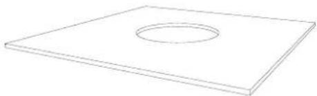
First, remove the ceiling tile and cut the required hole in the centre of the tile.
natural_image
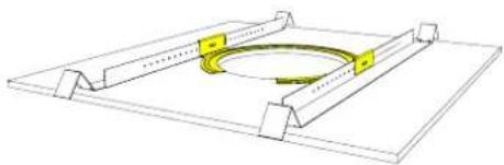
Simple line drawing of a rectangular plate with a circular hole in the center (no text or symbols)Place the tie rails either side of the hole orientate as shown ensuring that the ends align with the edge of the tile.

natural_image
3D diagram of a mechanical assembly with yellow components and a central circular hole (no text or symbols)Place the C-bracket in position over the hole with the clips hooked over the rails. Make sure the bracket is aligned accurately with the hole.
natural_image
Technical line drawing of a mechanical assembly with a circular component and flanges (no text or symbols)Screw the C-Bracket in place with the screws provided screwing from the hole side through to the rails. This will make it easier to access the screws if any adjustment is required one the tile and supporting brackets are in the ceiling.
natural_image
Technical line drawing of a mechanical assembly with a circular component and an inset showing a curved track (no text or symbols)
natural_image
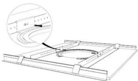
Diagram of a curved track with a cable and guide rail, showing structural components (no text or labels)The bracket assembly can now be placed in the ceiling. The ends of the tile rail can be easily re-shaped to fit onto the supporting frame for the ceiling. These simply hook on top of the ceiling frame; they are not fixed in position. The tile can now be replaced. This will inevitably mean lifting one side of the bracket, ensure that once the tile is back in position the frame is sitting on the ceiling frame and that the C-Bracket is accurately lined up with the hole. If necessary, reach through the hole and loosen the fixing screws holding the C-Bracket to the rails, make any adjustments to the position and tighten the screws.
Fitting the ceiling speakers
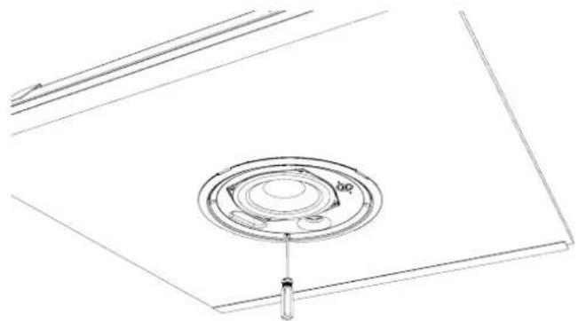
Once a suitable hole has been prepared the ceiling speakers can be fitted. First pull the cabling down through the hole, it is important that there is enough slack on the cable to allow easy connection of the cables to the speaker. Connect the cable as described in the Connections chapter. Fit a safety wire to the tab and ensure this is firmly attached to a fixing point independent of the ceiling structure.
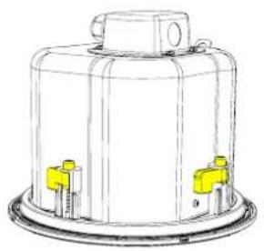
The ceiling speakers are held in position with swivel tabs which are at right angles to the final fixing position to allow placing the speaker in the hole, these then rotate 90° as the fixing screws are tightened to hold the speaker securely in place. Before inserting the speaker into the ceiling, ensure that all swivel tabs are rotated so they are parallel with the edge of the bezel to allow easy insertion up into the ceiling.
natural_image
Technical line drawing of a cylindrical industrial container with yellow connectors (no text or symbols)The connector cover sticks out at the side of the back can, this is to keep the depth of the speaker to a minimum to ensure that the speakers are suitable for shallow voids above ceilings.
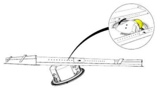
To fit the speaker, you will need to guide the connector cover and cables into the hole first and then raise the speaker into position flush in the hole.
natural_image
Diagram of a mechanical device with a magnified inset showing a component (no text or symbols present)
natural_image
Technical line drawing of a mechanical assembly with a central rotating component and mounting base (no text or symbols)If a quantity of ceiling speakers are deployed in a line (corridor) the tweeter should be orientated so that an imaginary line between the woofer and tweeter points along the line of speakers. This will minimise phase issues at the crossover point that are inevitable in a 2-way speaker.

natural_image
Pure technical diagram of a circular mechanical component with no text or symbolsThe ceiling speakers are secured by tightening the mounting screws from the front baffle. The ACS-40TS has three mounting screws, the ACS-55TS and ACS-55T have four. Tighten these clockwise, the swivel tables will rotate 90° and will then pull down onto the back of the tile to hold the speaker securely in place. A recommended torque setting of 0.5Nm and no more than 1Nm should be used to avoid over tightening.
natural_image
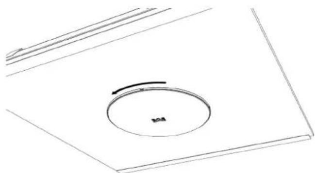
Technical line drawing of a circular component mounted on a base plate (no text or symbols)Fitting the grille
The grille is a simple bayonet fitting. Locate the lugs on the underside of the grille and position on the ceiling speaker. Rotate approximately 5^ and it will be fixed in place. It can be removed by rotating anticlockwise should any maintenance or adjustment be required.
natural_image
Pure technical line drawing of a circular component with a central arrow, no text or symbols presentADORN Pendant Deployment
ACP-55T
The ACP-55T is designed to be suspended in free space from a single point. The mounting tab on the top of the enclosure is used to attach the speaker to the means of suspension, wire rope or similar. The fixings used to attach the speaker must be rated for flown applications and have a safe working load that exceeds the weight of the ACP-55T.
natural_image
Black industrial lamp with a hook and small component on top (no text or symbols visible)Fitting the grille
The grille can be fitted before suspending the ACP-55T if the required electrical configuration is known; - low impedance or the specific 70v and 100v line tap. The grille is a simple bayonet fitting. Locate the lugs on the underside of the grille and position on the ceiling speaker. Rotate approximately 5° and it will be fixed in place. It can be removed by rotating anticlockwise should any maintenance or adjustment be required.
Important safety information
- Martin Audio ADORN ceiling speakers must be installed by experienced installation personnel using all accessories appropriate to the ceiling construction
- The installer must check with all relevant local, national and international electrical, fire and building safety authorities to ensure that all regulations are being complied with
- Every ADORN ceiling speaker must be fitted with a steel safety wire between its rear can safety tag and a suitable overhead supporting structure independent of the ceiling to provide secondary safety support in the event of damage to the ceiling
- When installed in an air handling space the steel cover plates must be sealed to the loudspeaker back cans with firestop putty or a suitable alternative to ensure plenum tight enclosure of the electrical connections.
Technical Specifications
A40/A40T
| TYPE Ultra-compact passive two-way system,front ported bass reflex | |
| FREQUENCY RESPONSE (1) 98Hz-17kHz ± 3dB | |
| -10dB @ 70Hz | |
| DRIVERS LF: 4" /1" high-temp voice coil, coated paper cone,rubber surround, ferrite motor, pressed steel chassisHF: 0.75" silk dome, neodymium motorRATED POWER (2) 40W AES, 160W peakRECOMMENDED AMPLIFIER A40: VIA2004A40T: VIA5002 | |
| SENSITIVITY (1) 87dB/1W/1mMAXIMUM SPL (9) 109dB peakNOMINAL IMPEDANCE 16 ohmsDISPERSION (-6dB) 110° H x 80° VCROSSOVER 3.5kHz passive (LF and HF auto-resetting fuses)TRANSFORMER TAPS (A40T only) 70V: 20w / 10w / 5w / 2.5w100V: 20w / 10w / 5w | |
| RECOMMENDED HIGH-PASS FILTER 60Hz 24dB/octENCLOSURE ABS, UL 94V-0 rated | |
| FINISH | Black or white |
| GRILLE | Perforated steel |
| CONNECTORS | Push terminals |
| FITTINGS | Wall bracket included |
| DIMENSIONS EXCL. BRACKET(W) 124mm x (H) 200mm x (D) 114mm(W) 4.9in x (H) 7.9in x (D) 4.5in | |
| WEIGHT | A40: 1.75kg (3.9lbs) |
| A40T: 2.13kg (4.7lbs) | |
| ACCESSORIES | Waterproof connector cover |
A55/A55T
| TYPE Ultra-compact passive two-way system, | |
| front ported bass reflex | |
| FREQUENCY RESPONSE (1) 90Hz-17kHz ± 3dB | |
| -10dB @ 65Hz | |
| DRIVERS LF: 5.25" /1" high-temp voice coil, coated paper | |
| cone, rubber surround, ferrite motor, pressed steel chassis | |
| HF: 0.75" silk dome, neodymium motor | |
| RATED POWER (2) 50W AES, 200W peak | |
| RECOMMENDED AMPLIFIER A55: VIA2004 | |
| A55T: VIA5002 | |
| SENSITIVITY (1) 90dB/1W/1m | |
| MAXIMUM SPL (9) 113dB peak | |
| NOMINAL IMPEDANCE 16 ohms | |
| DISPERSION (-6dB) 110° H x 80° V | |
| CROSSOVER 3.5kHz passive (LF and HF auto-resetting fuses) | |
| TRANSFORMER TAPS (A55T only) 70V: 30w / 15w / 7.5w / 3.75w | |
| 100V: 30w / 15w / 7.5w | |
| RECOMMENDED HIGH-PASS FILTER 60Hz 24dB/oct | |
| ENCLOSURE ABS, UL 94V-0 rated | |
| FINISH | Black or white |
| GRILLE | Perforated steel |
| CONNECTORS | Push terminals |
| FITTINGS | Wall bracket included |
| DIMENSIONS EXCL. BRACKET | (W) 152mm x (H) 245mm x (D) 140mm |
| (W) 6in x (H) 9.6in x (D) 5.5in | |
| WEIGHT | A55: 2.21kg (4.9lbs) |
| A55T: 2.81kg (6.2lbs) | |
| ACCESSORIES | Waterproof connector cover |
natural_image
Black rectangular speaker or audio device with visible sound waves and mounting holes (no text or symbols)
natural_image
Black rectangular speaker with visible sound waves and mounting holes (no text or symbols)ACS-40TS
TYPE Ultra-compact, passive two-way ceiling speaker, ported bass reflex
FREQUENCY RESPONSE (1) 106Hz-20kHz ± 3dB, -10dB @ 73Hz
DRIVERS LF: 4" /1" high-temp voice coil, coated paper cone, rubber
surround, ferrite motor, pressed steel chassis
HF: 0.75" silk dome, neodymium motor
RATED POWER (2) 40W AES, 160W peak
RECOMMENDED AMPLIFIER VIA2004 (for low-impedance operation)
SENSITIVITY (4) 86dB / 1W(4V) / 1m
MAXIMUM SPL (9) 108dB peak
NOMINAL IMPEDANCE 16 ohms
DISPERSION (-6dB) 180° conical up to 10kHz
CROSSOVER 3.5 kHz passive (LF and HF auto-resetting fuses)
TRANSFORMER TAPS 70V: 20w / 10w / 5w / 2.5w, 100V: 20w / 10w / 5w
RECOMMENDED HIGH-PASS FILTER 75Hz 24dB/oct
ENCLOSURE UL 94V-0 rated ABS baffle with steel backcan
FINISH Baffle and grille: RAL9016 white, Backcan: zinc plated
GRILLE Perforated steel, powder-coated, bayonet fitting
CONNECTORS Ceramic connector (in and link) located behind fire-retardant steel cover
ACCESSORIES (included) 2 tile rails, C-ring backing plate, Cut-out template
DIMENSIONS (OD) 221mm x (D) 98mm
(OD) 8.7in x (D) 3.9in
WEIGHT 2.2kg (4.8lbs)
ACS-55TS
TYPE Compact, passive two-way ceiling speaker, ported bass reflex
FREQUENCY RESPONSE (1) 117Hz-20kHz ± 3dB, -10dB @ 79Hz
DRIVERS LF: 5.25" /1" high-temp voice coil, coated paper cone.
rubber surround, ferrite motor, pressed steel chassis
HF: 0.75" silk dome, neodymium motor
RATED POWER (2) 50W AES, 200W peak
RECOMMENDED AMPLIFIER VIA2004 (for low-impedance operation)
SENSITIVITY (4) 90dB / 1W(4V) / 1m
MAXIMUM SPL (9) 113dB peak
NOMINAL IMPEDANCE 16 ohms
DISPERSION (-6dB) 150° conical up to 7kHz
CROSSOVER 3kHz passive (LF and HF auto-resetting fuses)
TRANSFORMER TAPS 70V: 30w / 15w / 7.5w / 3.75w, 100V: 30w / 15w / 7.5w
RECOMMENDED HIGH-PASS FILTER 65Hz 24dB/oct
ENCLOSURE UL 94V-0 rated ABS baffle with steel backcan
FINISH Baffle and grille: RAL9016 white, Backcan: zinc plated
GRILLE Perforated steel, powder-coated, bayonet fitting
CONNECTORS Ceramic connector (in and link) located behind
fire-retardant steel cover
ACCESSORIES (included) 2 tile rails, C-ring backing plate, Cut-out template
DIMENSIONS (OD) 245mm x (D) 102mm
(OD) 9.7in x (D) 4in
WEIGHT 2.8kg (6.2lbs)
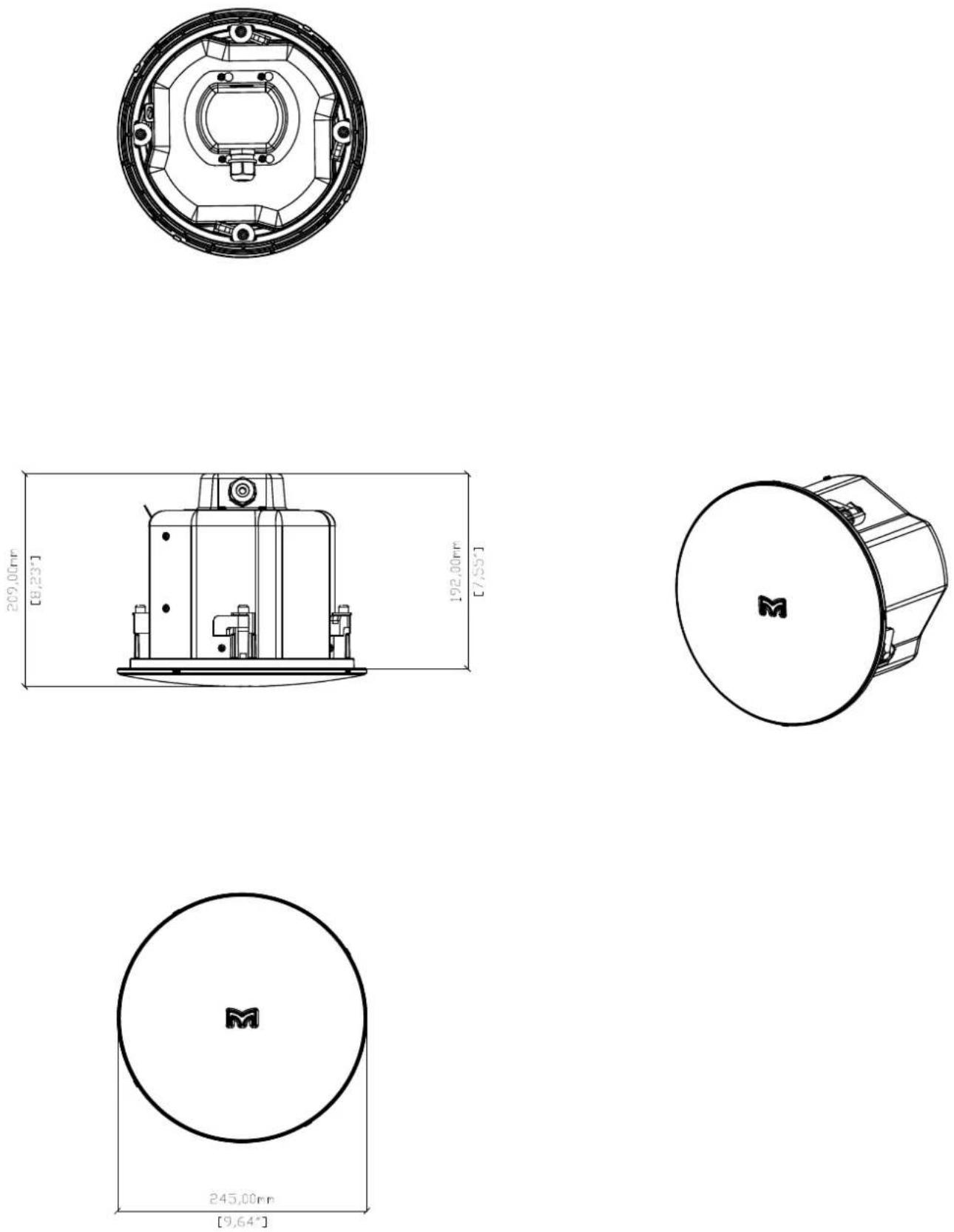
ACS-55T
TYPE Compact, passive two-way ceiling speaker, ported bass reflex
FREQUENCY RESPONSE (1) 98Hz-20kHz ± 3dB, -10dB @ 62Hz
DRIVERS LF: 5.25" /1" high-temp voice coil, coated paper cone.
rubber surround, ferrite motor, pressed steel chassis
HF: 0.75" silk dome, neodymium motor
RATED POWER (2) 50W AES, 200W peak
RECOMMENDED AMPLIFIER VIA2004 (for low-impedance operation)
SENSITIVITY (4) 90dB / 1W(4V) / 1m
MAXIMUM SPL (9) 113dB peak
NOMINAL IMPEDANCE 16 ohms
DISPERSION (-6dB) 150° conical up to 7kHz
CROSSOVER 3kHz passive (LF and HF auto-resetting fuses)
TRANSFORMER TAPS 70V: 30w / 15w / 7.5w / 3.75w, 100V: 30w / 15w / 7.5w
RECOMMENDED HIGH-PASS FILTER 65Hz 24dB/oct
ENCLOSURE UL 94V-0 rated ABS baffle with steel backcan
FINISH Baffle and grille: RAL9016 white, Backcan: zinc plated
GRILLE Perforated steel, powder-coated, bayonet fitting
CONNECTORS Ceramic connector (in and link) located behind fire-retardant steel cover
ACCESSORIES (included) 2 tile rails, C-ring backing plate, Cut-out template
DIMENSIONS (OD) 245mm x (D) 193mm
(OD) 9.7in x (D) 7.6in
WEIGHT 3kg (6.6lbs)
natural_image
Close-up of a white circular speaker with black speaker chamber and mounting holes (no text or symbols visible)
natural_image
Close-up of a white circular mechanical component with a black central cavity and mounting holes (no text or symbols visible)
natural_image
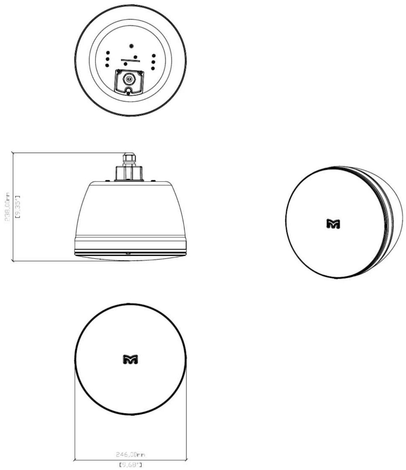
Close-up of a mechanical component with hexagonal opening and internal cavity (no text or symbols visible)ACP-55T
TYPE Passive two-way pendant speaker, ported bass reflex
FREQUENCY RESPONSE (6) 98Hz-20kHz ± 3dB
-10dB @ 56Hz
DRIVERS LF: 5.25" /1" high-temp voice coil, coated paper cone,
rubber surround, ferrite motor, pressed steel chassis
HF: 0.75" silk dome, neodymium motor
RATED POWER (2) 50W AES, 200W peak
RECOMMENDED AMPLIFIER VIA2004 (for low-impedance operation)
SENSITIVITY (7) 86dB / 1W(4V) / 1m (full space)
MAXIMUM SPL (9) 109dB Peak
NOMINAL IMPEDANCE 16 ohms
DISPERSION (-6dB) 150° conical up to 7kHz
CROSSOVER 3kHz passive (LF and HF auto-resetting fuses)
TRANSFORMER TAPS 70V: 30w/15w/7.5w/3.75w
100V: 30w / 15w / 7.5w
RECOMMENDED HIGH-PASS FILTER 65Hz 24dB/oct
ENCLOSURE UL 94V-0 rated ABS baffle and enclosure
FINISH Black or white
GRILLE Perforated steel, powder-coated, bayonet fitting
| CONNECTORS | Ceramic connector (in and link) |
| DIMENSIONS | (OD) 246mm x (D) 157 mm (175mm including grille) |
(OD) 9.7in x (D) 6.2in (6.9in including grille)
WEIGHT 3.46kg (7.62lbs)
Notes
(1) Measured on-axis in half (2pi) space at 2 metres, then referred to 1 metre.
(2) AES Standard ANSI S4.26-1984.
(3) Measured in half (2pi) space at 2 metres with 1 wall input.
using band limited pink noise, then referred to 1 metre.
(4) Measured in half (2pi) space at 2 metres using band limited
pink noise, then referred to 1 metre
(5) Measured on-axis in open (4pi) space at 2 metres, then referred to 1 metre.
(6) Measured in open (4pl) space at 2 metres with 1 watt input,
using band limited pink noise, then referred to 1 metre.
(7) Measured in open (4pi) space at 2 metres using band limited pink noise, then referred to 1 metre.
(8) Measured in open (4pi) space at 2 metres with 2.83v input,
using band limited pink noise, then referred to 1 metre,
(9) Calculated at 1 metre.
(10) Measured in half (2pi) space at 2 metres with 2.83V input,
using band limited pink noise, then referred to 1 metre.
natural_image
Close-up of a white cylindrical device with a hexagonal lens and central button (no text or symbols visible)Technical Drawings
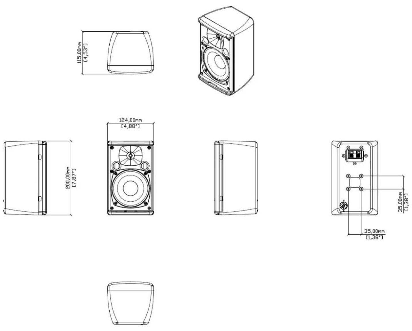
A40

text_image
115,00mm [4,53°]
natural_image
Line drawing of a speaker with visible sound waves and fan blades (no text or symbols)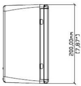
text_image
200.00mm [7,87*]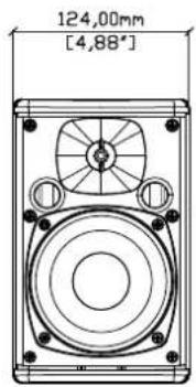
text_image
124,00mm [4,88°]
natural_image
Pure line drawing of a rectangular object with vertical connectors (no text or symbols)
text_image
35,00mm [1,38°] 35,00mm [1,38°]
A40T
A55

A55T
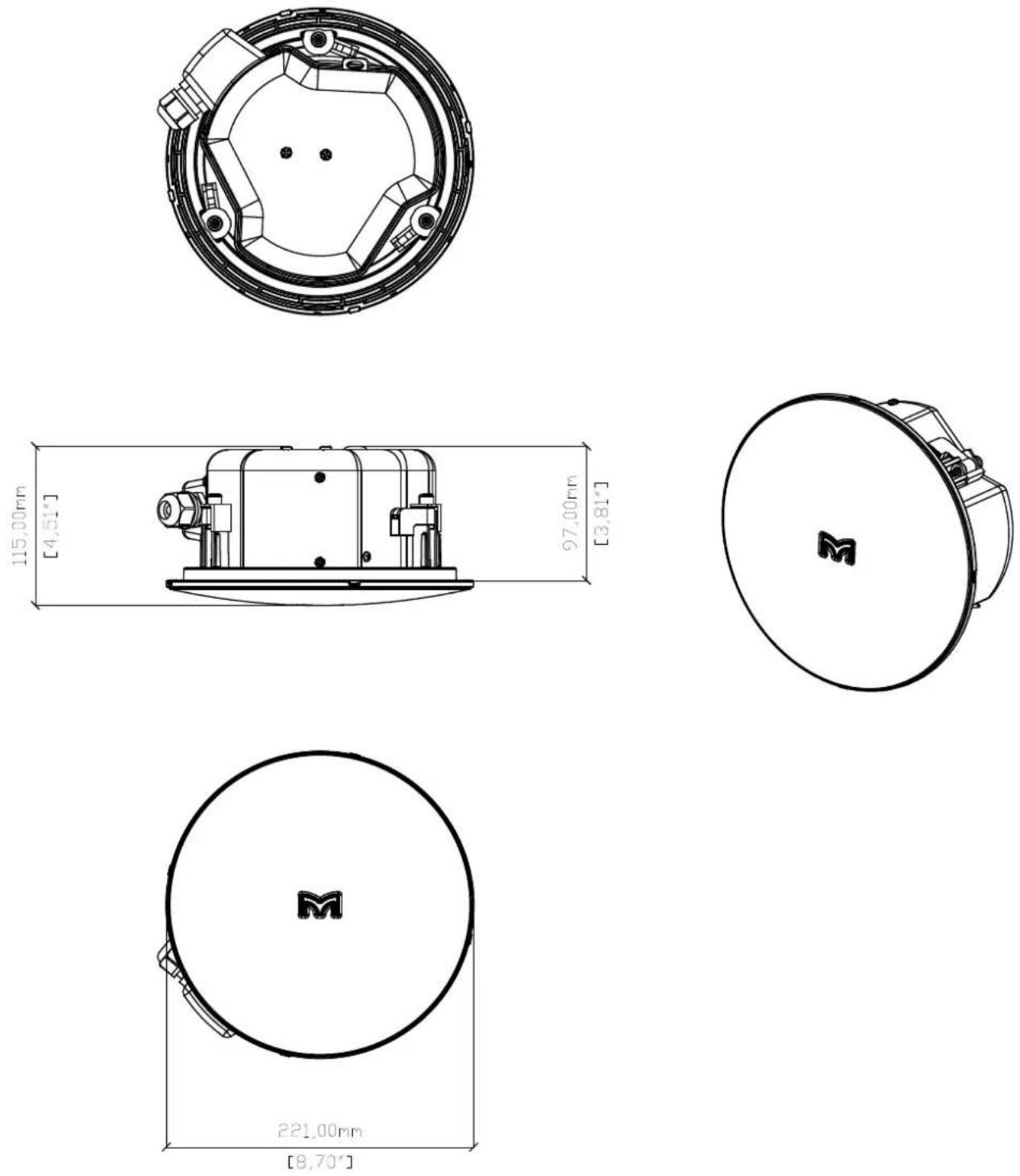
ACS-40TS
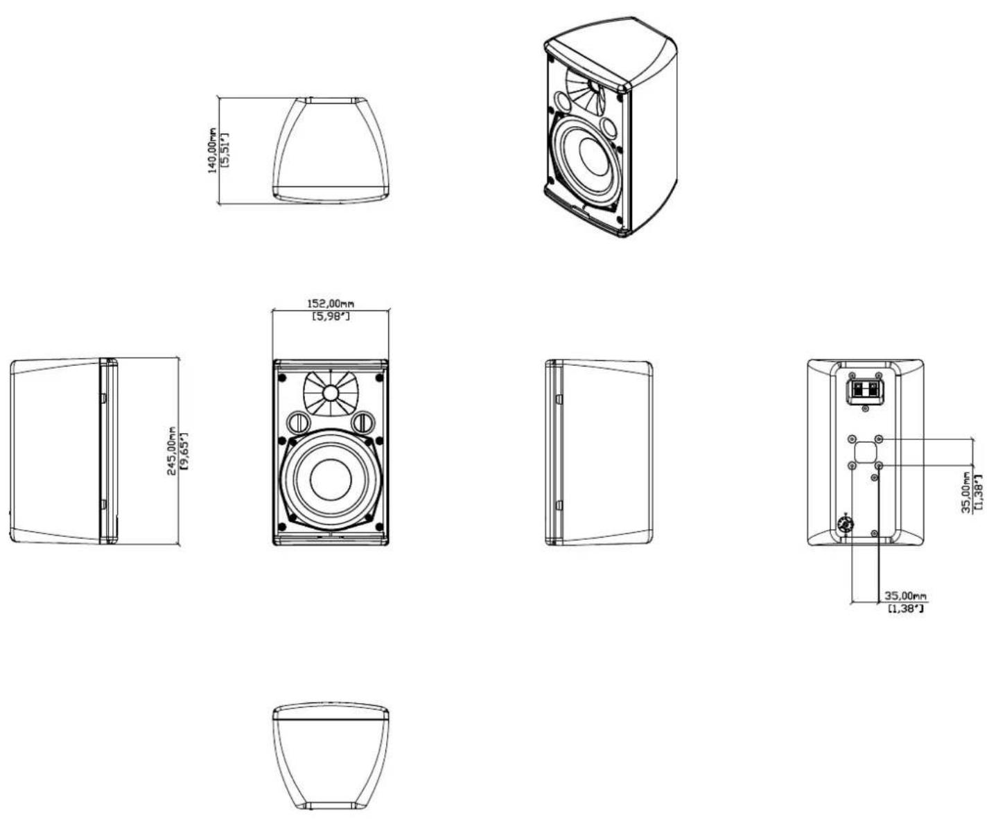
ACS-55TS

ACS-55T
ACP-55T
Warranty
Warranty Statement
Martin Audio ADORN series loudspeakers are warranted against manufacturing defects in materials or craftsmanship over a period of 5 years from the date of original purchase. During the warranty period Martin Audio will, at its discretion, either repair or replace products which prove to be defective provided that the product is returned in its original packaging, shipping prepaid, to an authorised Martin Audio service agent or distributor. Martin Audio Ltd. cannot be held responsible for defects caused by unauthorised modifications, improper use, negligence, exposure to inclement weather conditions, act of God or accident, or any use of this product that is not in accordance with the instructions provided by Martin Audio. Martin Audio is not liable for consequential damages. This warranty is exclusive, and no other warranty is expressed or implied. This warranty does not affect your statutory rights.
COPYRIGHT AND TRADEMARKS
Copyright Martin Audio Ltd. Martin Audio and ADORN series are trademarks of Martin Audio Ltd and are registered in the United Kingdom, United States and other countries. All other trademarks and trade names are the property of their respective owners.
2020 © Martin Audio Limited. All rights reserved.
Martin Audio Limited
Century Point
Halifax Road
Cressex Business Park
FOR SALES ENQUIRIES:
High Wycombe
Buckinghamshire
HP12 3SL
England
UK
Telephone: +44 (0)1494 535312
E-mail: info@martin-audio.com
NORTH AMERICA
Telephone: 323-381-5310
www.martin-audio.com
All information is Copyright © 2022 Martin Audio Ltd.
Martin Audio, the Martin Audio logo and Hybrid are registered trademarks of Martin Audio Ltd. in the United Kingdom, United States and other countries; all other Martin Audio trademarks are the property of Martin Audio Ltd.