L2500LP - Barbecue Sedona - Free user manual and instructions
Find the device manual for free L2500LP Sedona in PDF.

User questions about L2500LP Sedona
0 question about this device. Answer the ones you know or ask your own.
Ask a new question about this device
Download the instructions for your Barbecue in PDF format for free! Find your manual L2500LP - Sedona and take your electronic device back in hand. On this page are published all the documents necessary for the use of your device. L2500LP by Sedona.
USER MANUAL L2500LP Sedona
natural_image
Exterior view of a modern outdoor food grill with visible grating and cutlery, placed on a wooden deck with flowers and a white railing in the background (no signage or text)
WARNING
Read this manual carefully and completely before using your grill to reduce the risk of:
- Fire
- Burn hazard, personal injury or property damage
- Ruined steaks or other unpleasant cooking experiences
- Unapproved installation or servicing.
This product is designed for outdoor use only. Improper installation, adjustment, alteration, service or maintenance can cause property damage, injury or death.
Read this manual thoroughly before installation, use, or servicing of this product.

DANGER
IF YOU SMELL GAS:
- Shut off all gas supply lines to the grill.
- Extinguish any open flames.
- Carefully open the lid. Remember, it may be extremely hot!
If odor continues, keep everyone away from the grill and immediately call your gas supplier or your fire department.

DANGER
S'IL Y A UNE ODEUR DE GAZ:
- DO NOT store or use gasoline or other flammable vapors and liquids in the vicinity of this or any other appliance.
- An LP cylinder not connected for use shall not be stored in the vicinity of this or any other appliance.

AVERTISSMENT
- The burning of gas cooking fuel generates some by-products which are on the list of substances which are known by the State of California to cause cancer or reproductive harm.
- California law requires businesses to warn customers of potential exposure to such substances. To minimize exposure to the substances, always operate this unit according to the use and care instructions found in this manual. Be certain to provide adequate ventilation when cooking.
- California Proposition 65 lists "Silica, crystalline" which is used in one of the components of the IR burner, as an agent known to the state of California to cause cancer.

WARNING
- Never use dented, rusty or damaged propane cylinders. Never store additional or empty propane cylinders in the grill cabinet or in the vicinity of this or any other appliance. Do not store propane cylinders indoors or on their sides.
- Children should never be left alone or unattended in an area where a grill is located. Place your grill well away from areas where children play. Do not store items that may interest children in or around the grill, in the cart, or in the masonry enclosure.
- Never move the grill when hot. When in use, portions of the grill are hot enough to cause severe burns.
- Always maintain the required clearances from combustibles as detailed. The grill is designed for outdoor use only. Never use in a garage, building, shed, breezeway, or other enclosed area. Do not use this grill under any overhead combustible construction.
- Gas grills are not designed or certified for and are not to be installed in or on recreational vehicles, portable trailers, boats or any other moving installation.
- Always have an ABC Fire Extinguisher accessible — never attempt to extinguish a grease fire with water or other liquids.
- Storing your grill: Store your grill in a well-ventilated area. If stored indoors, detach and leave L.P. cylinder outdoors in a well-ventilated area away from heat and away from where children may tamper with it.
- Keep any electrical supply cord and the fuel supply hose away from any heated surfaces. Electrical cords should be placed away from walkways to avoid tripping hazard.
- Do not repair or replace any part of the grill unless specifically recommended in this manual. Other service should be performed by a qualified technician.
- If the grill is installed by a professional installer or technician, be sure that he/she shows you where your gas supply shut-off is located. All gas lines must have a shut-off that is readily and easily accessible. If you smell gas, check for gas leaks immediately. Check only with a soap and water solution. (See INDEX: "Leak Testing" for further details.) Never check for gas leaks with an open flame.
- Inspect the LP gas supply hose prior to each use of the grill. If there is evidence of excessive abrasion or wear, or the hose is cut, it must be replaced before using the grill
- Never remove the grounding prong from the plug or use this product with an ungrounded, 2-prong adapter.
- THIS MANUAL MUST REMAIN WITH THE PRODUCT OWNER FOR FUTURE REFERENCE.
This product complies with ANSI standard Z21.58/CSA 1.6 latest edition and has
been tested and approved by Intertek.

To obtain replacement parts or service contact:
Lynx Professional Grills
7300 Flores Street
Downey, CA 90242
888-289-5969
TABLE OF CONTENTS

natural_image
Close-up of a hand holding a mechanical component, no visible text or symbolsCARE & USE GUIDELINES
5
Important Safety Precautions 5
Sedona Grill Models 6
Grilling in Windy Conditions 6
Using Your Sedona Grill 7
Pre-Grill Checklist 7
Lighting Your Grill 8
Basic Grilling 10
Using the ProSear™ Burner 11
Using the Optional Rotisserie Burner 12
Cleaning Your Sedona Grill 14
Troubleshooting Your Sedona Grill 16
Contacting Lynx Customer Care 18
Warranty 19
INSTALLATION GUIDELINES
20
Before You Start 22
If shipment arrives damaged 22
Built-In Installations 22
Clearance to Combustibles 23
Cut Out Dimensions 24
Unpacking and Assembly 25
Gas Connections 26
Natural Gas 26
LP Gas 27
Gas Line Purging 28
Gas Conversion Kits 28
Electrical Connections 29
Connection to AC 29
Battery Installation 29
Final Checks 30
Leak Testing 30
Wiring Schematics 32
L400/L500 Non-Rotisserie Grill 32
L400/L500 Rotisserie Grill 33
L600/L700 Non-Rotisserie Grill 34
L600/L700 Rotisserie Grill 35
Sedona Grill Exploded Parts View 36
Sedona Grill Parts List 37
Model Specific BTU Outputs 38
Maximum Runs for all Appliances 38
Index 39
IMPORTANT SAFETY PRECAUTIONS
PLEASE REVIEW THESE IMPORTANT SAFETY PRECAUTIONS BEFORE YOU USE YOUR GRILL.
- NEVER LEAVE THE GRILL UNATTENDED WHILE COOKING.
- Ensure all tie-down straps have been removed from the burners.
- Always use caution when operating the grill in a windy area. (See INDEX: "Grilling in Windy Conditions" for further details.)
- Avoid wearing loose-fitting garments or long sleeves while grilling. They could ignite.
- Never touch the grill racks, hood or immediate surrounding metal surfaces with your bare hands while grilling.
- Use an insulated glove or mitt when opening and operating the grill. Always open the grill lid slowly to allow heat and smoke to escape before fully opening.
- The grill hood must be fully opened while lighting the grill. Releasing fuel into a closed grill before lighting will not make it light sooner or more efficiently. It will only risk explosion and personal injury or death. Never lean over a hot grill surface or look directly into the grill when attempting to light.
- Do not heat unopened food containers as pressure build-up will cause the container to explode.
- Do not use aluminum foil to line grill racks or drip pans. This will alter the airflow or trap excessive heat in the control area and can melt control knobs and ignition modules. Such damage is specifically excluded from your warranty.
-
Never use charcoal or any other solid fuel in the grill.
-
Cooking excessively fatty meats and oils will cause flare ups. Internal fires or damage caused by them or by the grill being left unattended while cooking are not covered under the terms and conditions of our warranty.
- Never grill without the drip pan in place. Always ensure the drip pan is pushed all the way to the back of the grill. Hot grease can leak downward and produce a fire or explosion.
- Grease is extremely flammable. Let hot grease cool down before attempting to handle or dispose of it. The drip tray should be cleaned of grease on a regular basis.
- Do not use the grill unless a leak check has been performed on all gas connections. (See INDEX: "Leak Test Procedure" for further details.)
- Never operate the grill while under the influence of alcohol or drugs.
- Do not lean on side shelves and never place a load weighing more than 25 pounds on a side shelf.
- If any burner does not light or goes out during operation, turn off all gas control knobs, open the hood and wait five (5) minutes before attempting to re-light.
- Portable LP cylinders: Always shut off the main valve on the LP cylinder after each use.
- Spiders and insects like to nest in the burners, venturis, valves and orifices of a grill, disrupting the gas flow. This very dangerous condition can cause a fire behind the control panel, damaging the grill and risking personal injury. If your grill has been unused for a long time, inspect and clean the burners, venturis, valves and orifices. (See INDEX: "Cleaning the Burner" for further details.)
SEDONA GRILL MODELS
This manual covers the following models, with or without Rotisserie burners. The freestanding carts are sold separately when use as a freestanding grill is desired.
MODEL DESCRIPTION
| L400PS; L500PS 1 Stainless Steel Tube Burner and 1 ProSearTM Burner |
| L600PS/L700PS 2 Stainless Steel Tube Burners and 1 ProSearTM Burner |
| L400PSR; L500PSR 1 Stainless Steel Tube Burners and 1 ProSearTM Burner and Rotisserie |
| L600PSR/L700PSR 2 Stainless Steel Tube Burners and 1 ProSearTM Burner and Rotisserie |
| L400/L500/L600/L700CART Freestanding Cart for the Sedona Series, Available Separately |
GRILLING IN WINDY CONDITIONS
Outdoor grills create more heat than interior kitchen ranges. That's how they sear and grill steaks and other foods.
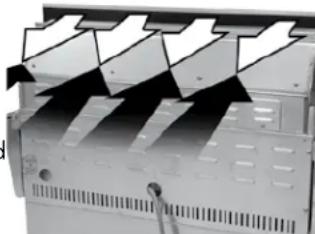
These high-performance burners require a constant, steady supply of fresh air to mix with the fuel. Your Sedona grill pulls air in through the front and vents hot gases out through the rear.

text_image
FRESH AIR INUsing your grill in windy conditions may disrupt the front-to-back air flow. If, while grilling with all burners on high and the hood closed, you notice that the temperature gauge fails to rise ... be careful. If wind has kept hot gases from exiting the rear of the grill the control panel and knobs may have become extremely hot.
IMPORTANT!

natural_image
Mechanical device with multiple blades and mounting holes (no visible text or symbols)◀ Wind hitting the back of the grill can disrupt proper exhaust.
There are a few things you can do to further prevent the possibility of improper heat buildup:
- On breezy days, be careful not to leave the front hood down for more than 15 minutes when the burners are on high. (Never leave the grill unattended when in operation)
- If you suspect the grill is overheating, using an oven mitt, open the front hood. Then adjust the burner control knob to a lower setting.
• Install your grill with a wind break behind it. - Orient the grill so prevailing winds are not blowing into the rear of the grill.

Please Note: Any damage caused from use in windy conditions, such as melted knobs or igniter wires, or control panel discoloration from heat buildup, is excluded from warranty coverage.
USING YOUR GRILL
Grilling requires high heat for searing and low, controlled heat for slow cooking. Thinner cuts of food are often cooked at a "HI" heat setting with the lid open. On the other hand, large, thick pieces of meat or poultry are often first seared at the high setting and then grilled at a lower setting ... sometimes with the lid closed ... achieving the best results in the middle of the food without burning the outside. Some foods are cooked using direct heat and some using indirect heat.
Your grill features a variety of professional-level burners and tools for meeting the wide variety of cooking challenges. We will reveal how these features work for you. So please read and enjoy!
Depending on the model you chose, your grill may be equipped with up to three different burner types. The operation of each type varies, so it is important to understand all three.
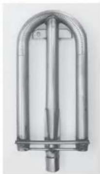
natural_image
Metallic cylindrical device with arched top and central shaft (no visible text or symbols)Main Stainless Steel Burner
The durable stainless steel burner is the standard main burner found under the briquette tray.

natural_image
Pure electrical circuit lines without any symbolsProSear™ Burner
This advanced infrared burner provides high-intensity infrared heat for searing foods and sealing in flavor, and can also be turned down for slower cooking.
Rotisserie Burner (optional)
This infrared burner spans the back of the cooking area and provides consistent heat for rotisserie cooking.
PRE-GRILL CHECKLIST
BEFORE YOUR FIRST USE
There are a few must-check safety precautions to consider before you use your grill. Please be sure that:
- All packing materials and tie-downs have been removed from the burners. (See INDEX: "Unpacking and Assembly" for further details.)
- You have fuel connected. (See INDEX: "Gas Requirements" for further details.)
- You have electrical connected and/or fresh batteries. (See INDEX: "Electric Requirements" for further details.)
- A qualified plumber has performed a leak test on all the fittings that supply fuel to your grill.
IF YOUR GRILL DOES NOT LIGHT IN 4 TO 5 SECONDS
you may need to purge the line. (See INDEX: "Purging the Gas Line" for further details.)
AT EACH NEW SEASON
At the start of each new grilling season you should remove the grilling racks and check the burners, venturis, orifices and valves for obstructions.
Spiders and insects often nest in these areas of the grill and can disrupt air flow, causing damage to the grill and personal injury.
Also, check all hoses and fittings for damage, abrasion, wear and tear.
BEFORE EACH USE
Before any use, always make sure that:
- ... you do not smell gas before you light the grill. If you do smell gas, shut everything off and have a qualified plumber check for leaks.
- ... the cooking area is free and clear of any combustibles, besides your food, that might ignite.
• ... the control knobs turn freely. - ... if you are using a portable propane cylinder, it is securely connected and leak tested. (See INDEX: "Cylinder Retention Instructions" for details.)
• ... you know where the main gas supply shut-off is located.
- ... the burners are seated properly in the grill with mounting legs in the slots. The main burners must sit level and firmly on the burner support frames. (See INDEX: "Unpacking and Assembly" for details.)
- ... wind is not blowing too strongly or blowing on the back of grill.
LIGHTING YOUR GRILL

WARNING
- Never attempt to light a burner if you smell gas.
- Always keep the lid open (side-burner lids must be completely removed) when lighting your grill.
- Releasing fuel into a closed grill before lighting will increase the risk of explosion, property damage, personal injury or death.
- Keep your face and body as far from the grill as possible when lighting. Any time a burner doesn't light within 5 seconds, turn off the control, wait 5 minutes for gas to dissipate, and repeat the lighting procedure.
- YOU NEVER LEAVE THE GRILL UNATTENDED WHILE COOKING.
ELECTRIC IGNITION
Before proceeding, make sure you have completed the "Before Each Use" checklist.
Follow these steps to light any of the burners on your grill:
First, make sure all burner control knobs are set to OFF.

Test the ignition system by pressing the control knob in and listening for a clicking sound of the igniters. If no clicking sound occurs, proceed to TROUBLE SHOOTING or MANUAL LIGHTING sections.
For the Main or ProSear™ Burner:
Push and hold the control knob in and rotate the knob to "LITE". After ignition, set the knob to the desired heat setting.
If the burners do not light with in 5 seconds, turn the knob to OFF and wait 5 minutes for gas to dissipate, and repeat the step above.
For the Optional Rotisserie Burner
The rotisserie burner features a thermocouple sensor with a safety valve that automatically shuts off the flow of gas if the burner goes out. (See INDEX: "Windy Conditions" for tips on how to prevent burner blow out)
To light the rotisserie burner, push and hold the control knob in for 2 seconds and then turn the knob to the "LITE" position.
After ignition CONTINUE HOLDING THE CONTROL KNOB IN for 30 to 60 seconds. During this time the thermocouple will heat up and the safety valve will remain open.
If you release the control knob before the thermocouple has heated up, the safety valve will shut off the flow of gas to the rotisserie burner and you will have to re-light the burner.

COLD WEATHER WARNING: PROPANE
WARNING
Extremely cold temperatures may cause your ProSear™ burner to light inside the burner instead of outside. Once lit, if you hear a 'whooshing' sound, immediately turn the burner knob off to extinguish the flame and then immediately re-light the burner.
MANUAL LIGHTING
If a burner doesn't light after several attempts, it can be match lit using the lighting rod stored in the drip tray.
First, make sure you've returned all of the control knobs to the OFF position and have allowed 5 minutes for any accumulated gas to dissipate before attempting to match light a burner.
Main Burner
To match-light this burner, use the lighting rod to insert a lit match through the cooking grate into the front slot of the briquette tray for that burner.
Push and turn the corresponding burner control knob to "LITE". If the burner doesn't light within 5 seconds turn the knob off and wait 5 minutes before attempting to light it again.

text_image
INSERT LIT MATCH HERE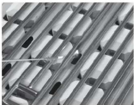
natural_image
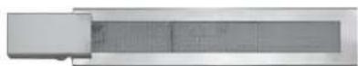
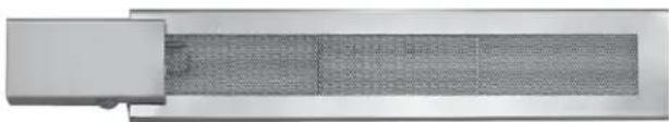
Close-up of a metallic grid structure with embedded rectangular components (no text or symbols visible)ProSear™ Burner
To match-light this burner, use the lighting rod to insert a lit match through the cooking grate.
Push and turn the corresponding burner control knob to "LITE". If the burner doesn't light within 5 seconds turn the knob off and wait 5 minutes before attempting to light it again.
natural_image
Close-up of metallic grid panels with no visible text or symbolsRotisserie Burner
To manually light this burner, use the lighting rod to hold a lit match at the face of the burner, push in and turn the control knob to the "LITE" position. Hold the knob in for at least 30 seconds. If the burner does not stay lit, turn the knob OFF and wait 5 minutes for gas to dissipate before attempting to light it again.
BASIC GRILLING
PRE-HEATING
Pre-heating your grill every time you use it is extremely important. Pre-heating allows the briquettes to properly heat up, providing more even and more consistent cooking results.
Pre-heat your grill by igniting all main burners, including ProSear™ burner, if provided, and setting them to "HI".
Then close the hood and allow the grill to heat for 10 to 15 minutes. Once you've reached your desired pre-heat temperature, turn off the burner that you won't be using to cook your food.

WARNING
DO NOT LEAVE THE GRILL UNATTENDED DURING THE PREHEAT CYCLE OR AT ANY TIME WHILE THE GRILL IS IN USE.
PREHEATING FOR MORE THAN 15 MINUTES MAY OVERHEAT THE GRILL, CAUSING DAMAGE TO THE GRILL.
TYPES OF COOKING
The main burners and the ProSear™ burner in your grill are capable of creating a range of temperatures. By varying the heat output, the number of burners used and the position of the hood, you can create either direct or indirect heat or a combination of both and develop a wide variety of succulent recipes. There are two basic types of grilling in an outdoor grill... Direct Heat and Indirect Heat:
Direct Heat
Direct heat cooking occurs when foods are placed directly over the heat source. This form of heat is known as "radiant" heat because the heat radiates directly from the source to the food.
Direct heat is a must when you want to sear the outside of your food to seal in flavor. The ProSear™ Burners provide the heat necessary to sear foods and seal in flavor.
Indirect Heat
Indirect heat cooking occurs when the food is not close to the heat source. Heat reaches the food via air movement within the cooking area. This form of heat is known as "convection" heat.

natural_image
Interior view of a stainless steel kitchen appliance showing internal compartments and ventilation ducts (no text or symbols visible)Indirect, or "convection" cooking is achieved by placing the food on one side of the grill and igniting burners on the other side. You leave the burner below the food "OFF". You should keep the hood closed as much as possible during this type of cooking to maintain even heat around the food. You regulate the heat by adjusting the burner, using the hood thermometer to monitor the temperature.
USING THE PROSEAR™ BURNER
Professional restaurant chefs rely on a different type of heat ... infrared heat ... to create a higher searing temperature than what standard burners can achieve. So the ProSear™ infrared burner is provided for this purpose.
Infrared burners work by focusing the gas flame through a ceramic element filled with tiny holes.
These holes focus the flame on the surface of the element, creating an intense heat much higher than that of a standard burner. It allows you to sear your food more quickly while leaving the inside rare, if desired.
The ProSear™ burner, with its advanced components, requires particular attention to lighting, usage and cleaning guidelines. (See INDEX: "ProSear™" for further details.)
Preheating the ProSear™ Burner
Always preheat the entire grill before cooking to achieve consistent, successful results. (See INDEX: "Preheating" for further details.)
If the grill is already hot from cooking you should still pre-heat the ProSear™ burner for 2-3 minutes, or until it glows red.
Avoid placing food over a ProSear™ burner before it is fully pre-heated because food particles and grease dripping onto a cold ProSearTM burner may clog the ports and damage the burner.
For the same reason you should minimize water spills on the ProSear™ burner and should not use water to control flare-ups. Take special care to minimize dropping water on the ProSear™ burner while cleaning the cooking grids.
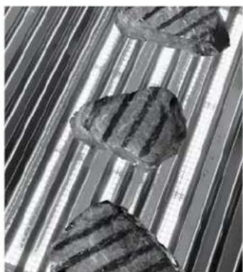
HOW TO SEAR
Searing locks in flavor and juices while allowing the food's outer surface to absorb smoke and food-born aromas produced when drippings are vaporized by the burner.
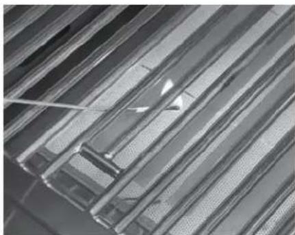
natural_image
Close-up of three textured, striped objects arranged on parallel metallic strips (no text or symbols visible)The result is a restaurant-style finish ... crisp, flavorful outside with a tender, juicy inside.
While the burners in your grill are capable of producing searing heat, the ProSear™ infrared burner is specifically designed for this purpose.
This burner is unique in that it can be turned down for slower cooking at a reduced temperature
SAFETY PRECAUTIONS
The cooking grids are heavy duty. Dropping them on the ProSear™ burner will damage the burner. Such damage is not covered by the product warranty and will cause a fire, burns or other personal injury.
USING THE OPTIONAL ROTISSERIE BURNER
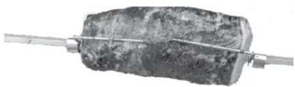
Rotisserie cooking provides an even delivery of heat to your foods. It has no equal. The constant rotation not only cooks foods evenly, it also self bastes. As juices rise to the surface of the food, they naturally flow around it as it rotates. The position of the rotisserie burner avoids scorching flare-ups.
natural_image
Close-up of a dark, textured object being cut with a metal rod (no visible text or symbols)Your foods will be more evenly cooked, more tender and juicier when slow-roasted on the rotisserie.
natural_image
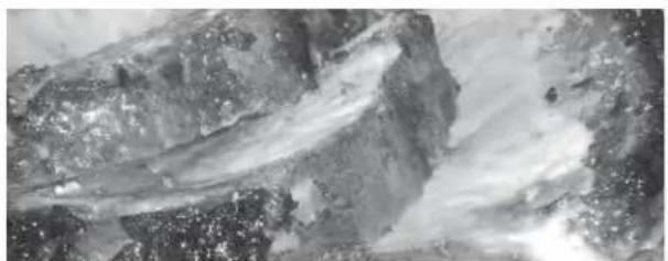
Monochrome abstract texture with swirling patterns and no visible text or symbolsThe rotisserie system consists of four main parts, the motor and bracket, the skewer, the forks and the infrared burner
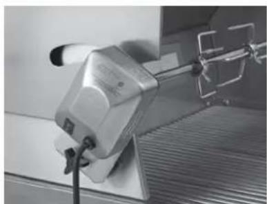
The Motor
Install the motor by sliding it onto the bracket as shown.
The rotisserie motor bracket may be easily removed by turning the black knob counterclockwise until the bracket disengages from the hood side.
natural_image
Close-up of a mechanical device with a metallic component and a transparent housing (no visible text or symbols)Plug the rotisserie motor power cord into a 110 Volt 15Amp, GFI outlet. Your grill and rotisserie motor must be plugged in to work. It is recommended that you place a bast-
ing pan to prevent food accumulations on the briquettes and burners. But BE SURE YOU REMOVE IT before using any of the other burners.
The location of the rotisserie burner makes it more susceptible to strong wind conditions (more so than the main grill burners).
For this reason it features a safety valve that automatically closes any time the rotisserie burner is not properly lit ... like if it were to extinguish in windy conditions. During windy conditions, it's best to keep the lid closed and to periodically check the burner.
The Skewer & Forks
The rotisserie can handle large food items. You should prepare any item and first mount it on the skewer.

natural_image
Metallic stirrer with multiple blades and a central handle (no text or symbols visible)To load the skewer, slide one of the forks onto the skewer. Push the skewer through the center of the food, then slide the second fork onto the skewer. Center the food to be cooked on the skewer then push the forks firmly together. Tighten the thumb screws (use pliers if necessary). You should wrap any loose, dangling pieces of food (such as wings) with butcher's string (never use nylon or plastic string).
With the food secured to the skewer slowly roll the skewer in the palms of your hands to check for balance. It should
rotate smoothly. If you find it has a heavy side, adjust where the skewer pierces the meat. An unbalanced skewer will cause uneven rotation and uneven cooking.
natural_image
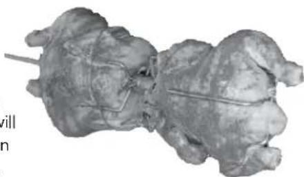
3D rendered anatomical model of a biological structure, possibly a fossil or organ, with no visible text or symbols.Mount the skewer on the grill before lighting the rotisserie infrared burner. Lighting the burner first could result in burning your hands while trying to mount the skewer on the grill.
Slide the pointed end of the skewer into the motor and rest the other end on the support on the right side of the grill.
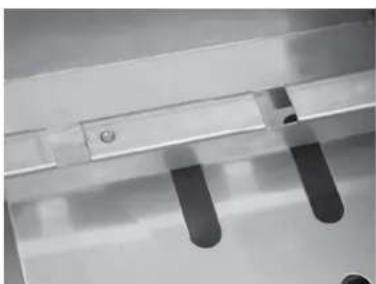
The notched portion of the skewer must rest on the support for proper operation. (see photo at right)
USING THE OPTIONAL ROTISSERIE BURNER... continued
The Rotisserie Burner
To light the rotisserie infrared burner, first mount the skewered food item on the grill then follow the rotisserie lighting procedure. (See INDEX: "Rotisserie Burner, Lighting" for further details.)
natural_image
Close-up of a metallic panel with a rectangular cutout and a grid-patterned side (no visible text or symbols)Once lit, the rotisserie burner should reach cooking temperatures in about 1 minute. It will glow evenly across its surface in about 5 minutes.
NOTE: The hood thermometer is only an indication of the radiant heat inside the grill. When cooking on a rotisserie use a meat thermometer to check the internal temperature of the food to determine doneness.
If the burner will not stay lit when you release the control knob, re-light it and hold the control knob in for at least 60 seconds to allow the thermocouple to heat up.
If the burner will not remain lit refer to the troubleshooting guide for assistance.

text_image
MUST REST ON SUPPORTSNotched portion of the skewer must rest on the support
STAINLESS STEEL
Our grills are known for their attractive appearance. We achieve this by selecting only the finest grades of stainless steel and applying exacting workmanship.
In order to maintain this attractive appearance over the life of the grill it is important to take the following steps:
- After each use wipe down the exterior of the grill to remove grease and splatters.
- Be sure to follow the cleaning instructions for keeping the grates and burners clean and ready for use.
- Use a commercially available Stainless Steel cleaner to clean and polish the exterior surfaces.
- Doing these things on a regular basis minimizes the amount of effort required.
- Part of the appeal of your grill is the fine grain finish. When removing stubborn stains do not use metallic abrasives
and always rub in the direction of the grain.
- Some household cleaning products are not suitable for stainless steel; be sure to

text_image
GRAIN DIRECTIONread the label before using on your grill.
- Always use the mildest cleaning solution first, scrubbing in the direction of the grain. Specks of grease may gather in the grain of the stainless steel and bake on to the surface, giving the appearance of rust.
- To remove these baked-on foods use a fine to medium grit non-metallic abrasive pad (Scotch Brite is good) in conjunction with a stainless steel cleaner.
- Solutions used for cleaning concrete and masonry can be very corrosive and will 'attack' stainless steel. Ensure your products are well protected before you allow the use of such chemicals near your grill.
SPECIAL NOTE FOR LOCATIONS NEAR POOLS AND COASTAL AREAS
The stainless steel material used in the construction of your grill is rust resistant, however, chlorine in the air from swimming pools or the salt from sea air may cause surface rust to appear and even create some pitting if left on the product.
Here are a few tips to avoid this:
- Regularly wipe down the exterior surfaces with a damp cloth. (Micro fiber cloths such as Ecloth perform very well).
- Allow the surfaces to dry before installing the cover. Do not cover a damp grill.
- In extreme environments apply a rust inhibitor which leaves a microscopic protective layer on the grill. Products that provide a layer of vapor corrosion inhibitors (VpCI™) protect the surface very well.
- For seasonal storage use the product referred to above, ensure the grill is dry and then cover and secure the cover to minimize the amount of damp air getting to the surfaces.
THE LIMITED LIFE TIME WARRANTY PROVIDES PROTECTION AGAINST RUST-THROUGH OF PARTS THAT RENDER THE PRODUCT INOPERATIVE. IT DOES NOT COVER OCCASIONAL SURFACE RUST OR STAINING DUE TO ENVIRONMENTAL CONDITIONS.
After your first use certain areas of the grill may take on a straw color from the intense heat given off by the burners - this is normal and cannot be cleaned off.
For light and heavy food stains there are many different stainless steel cleaners available.
DRIP TRAY
The drip tray should be cleaned periodically. After the grill is completely cool, remove the drip tray by pulling it out until it stops, then lifting the front edge until the drip tray comes free. Clean it with hot soapy water or an oven-style cleaning product and re-install. When using an oven-style cleaning product be sure to carefully follow the manufacturer's instructions. Many of these cleaners are toxic and can damage the stainless steel finish if not used properly.
Also, check the tray after for water accumulation after it rains.

WARNING
DO NOT ALLOW EXCESS GREASE OR LIQUIDS TO ACCUMULATE IN THE DRIP TRAY AS THIS MAY CREATE A FIRE HAZARD.
NEVER USE GRILL WITHOUT DRIP TRAY PROPERLY INSTALLED.
CLEANING YOUR GRILL ...continued
GRILLING RACKS
The easiest way to clean the grill racks is to do so immediately after turning off the burners, while they are still hot. Wearing a long BBQ mitt to protect your hand from steam, dip a brass bristle brush in hot water and scrub the grill rack. Dip the brush frequently because the steam helps remove baked-on foods.
CERAMIC BRIQUETTES
The ceramic briquettes normally burn off any accumulated food drippings. But you may occasionally experience larger spills that don't burn off under normal use.
When this happens, let the grill cool completely. Remove the racks and then the briquette trays by lifting the front edge and pulling them toward you. Flip the trays over and put them back in place over the burner. Light the burners
and set them to "HI" for 5-10 minutes to burn the briquettes clean.
Any remaining food items can be brushed off using a soft brush.

natural_image
Close-up of a grid of white electronic components or modules arranged in rows (no visible text or symbols)Replacement briquette trays can be ordered from Lynx Customer Care.
MAIN BURNERS
Make sure the grill is completely cool before proceeding.
Ensure that the gas supply is off and all control knobs are in the "OFF" position.
To Remove Burners:
- Remove the grill racks and briquette trays.
- Remove the hex head bolt securing the burner.
- Lift the burner up at the rear until the legs exit the frame.
- Then pull to the rear of the grill so the burner head comes off the orifice at the front.
- Angle the burner sideways and lift it out.
Be careful not to change the air shutter position.
To Clean the Burner:
To maximize grill performance, clean the exterior of the burner with a brass wire brush. Remove stubborn scale with a metal scraper.
Clear any clogged ports with a straightened paper clip. Never use a wooden toothpick as it may break off and clog the port.
Shake out any debris through the air shutter.
Use a flashlight to inspect the burner inlet to ensure it is not blocked. If obstructions can be seen, clean it with a paper clip or a pipe cleaner.

WARNING
PROPER PLACEMENT OF EACH BURNER IS CRITICAL. AFTER CLEANING THEY MUST BE CENTERED ON THE ORIFICE, RESTING LEVEL WITHOUT ANY ROCKING. REPLACE THE HEX HEAD SCREW TO SECURE THE BURNER.
FAILURE TO MEET THESE CONDITIONS MAY CAUSE A VERY DANGEROUS CONDITION THAT CAN CAUSE PERSONAL INJURY AND PROPERTY DAMAGE.

text_image
Orifice all the way into the venturiPROSEARTM BURNER
It's easy to keep your ProSear™ burner operating at peak performance. Just run it on "HI" with the hood open for 5 minutes after each use to burn away any food particles or drippings.
Any ash accumulation on the burner surface can be removed with a light brush or vacuum ... BUT WAIT UNTIL THE BURNER IS COOL!
Every 3 to 6 months, remove the burner (it's held in place by a hex head screw) and inspect the venturi (inlet) and orifice to ensure that they're free of obstructions.
Food debris on the inside of the burner can be gently shaken out. Do not touch the ceramic surface.
Clean any obstructions with a straight piece of metal coat hanger, pipe cleaner or paper clip.
When re-installing the ProSear™ burner, be sure to correctly position the burner. Replace the hex head screw to secure the burner.
TROUBLESHOOTING YOUR GRILL
BEFORE YOU CONTACT LYNX CUSTOMER CARE
Please check a few things before calling for service:
• Is there fuel supplied to the grill?
• Is the main shut-off valve open?
- Are you using the correct type of fuel? (LP or Natural Gas) (See INDEX: "Gas Requirements" for further details.)
- Is your propane cylinder empty? Have you recently refilled the propane cylinder? If so, is the connection tight?
- Have you opened the valve on the propane cylinder?
- Is the grill plugged in to a live electric circuit? If not, has the 9V battery been replaced recently?
If you've checked the above items, review the troubleshooting list below before calling the manufacturer for service.
LIGHTS WON'T LIGHT
Check Power
Ensure that the grill is connected to a GFI protected, live AC power source and that he GFI device has been reset.
Reset Transformer
Disconnect power from the grill and wait 5 minutes for the transformer to cool down and reset. Then reconnect power. If, after resetting the transformer and replacing bulbs, you still do not have power, contact Lynx Customer Care.
Replace the Bulb
Replacement bulbs are halogen, 12 volt, 10W max, T3 type with a G4 bi-pin base, and are readily available at most stores. The glass cover is held in place by two spring tension tabs. The bulbs are easily removable without the use of tools. Simply grasp the glass lens at the outer corners, near the front tension clips and push the lens back. Then, swing the lens down and pull it loose. You may have to loosen the screw to remove the lens.
Avoid touching the glass of a new bulb. Halogen bulbs are very sensitive to the oils found in human skin. Touching the bulbs may shorten their life.
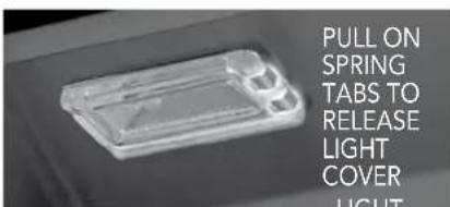
text_image
PULL ON SPRING TABS TO RELEASE LIGHT COVER LIGHTPull the bulb straight out from the socket without twisting.
Hold the bulb using a paper towel or other cloth and gently press it straight into the socket. The glass cover should be gently snapped back into place.
GRILL WON'T LIGHT
First, confirm that the grill is getting electricity by turning on the lights, then:
Check the Igniters
Your grill uses an electric ignition system that creates a spark when the gas control knob is pushed in.
- Ensure that all burner controls are set to OFF.
- Remove the cooking grates and briquette trays.
- Watch and listen to all igniters as you push in and hold the corresponding control knob. (Be sure you push in the correct control knob and keep the knob in the "OFF" position)
- Listen for a rapid clicking sound when the control knob is pushed in. You should also see an electrical spark jump
between all the ignition electrodes. If no clicking is heard, and no spark is seen, check the electrical connections or try replacing the 9 volt battery. If the power is OK ensure that there is a proper gap of approximately 1/8" between the electro

natural_image
Close-up of a metallic door with a handle and metal bracket, mounted on a perforated metal panel (no text or symbols visible)- Check the remaining igniters. If igniters don't spark, proceed with troubleshooting or match-light the burner.
Check the Burners
If the igniters are working check to see if gas is reaching the burners by attempting to match light a burner.
BE CAREFUL! IF THE BURNER FAILS TO IGNITE, WAIT 5 MINUTES BEFORE ATTEMPTING TO IGNITE OTHER BURNERS! (See INDEX: "Match Lighting" for further details.)
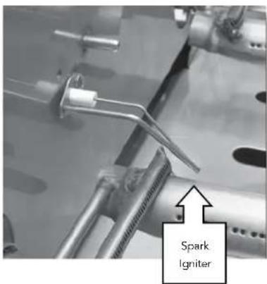
text_image
Spark IgniterIf match lighting doesn't work, re-check fuel connections for leaks and ensure the supply is of the correct type and is of adequate pressure. (See IN-DEX: "Leak Test" for further details.)
TROUBLESHOOTING YOUR GRILL... continued
If the burner will light with a match, then the igniter may not be functioning correctly. Contact Lynx Customer Care.
If the burner will not match light, and you know you are getting gas, wait for any gas to dissipate and remove the burner and check it for blockages. (See INDEX: "Clean the Burner" for further details.)
SMELL OF GAS WHILE COOKING
IF YOU SMELL GAS WHILE THE GRILL IS OPERATING, IMMEDIATELY TURN OFF ALL BURNERS AND SHUT OFF THE MAIN FUEL SUPPLY.
- Perform a leak test (See INDEX: "Leak Test" for further details.)
- Check for blockages (See INDEX: "Clean the Burner" for further details.)
YELLOW FLAMES
Under normal conditions the flames should be blue with slight yellow tips. (See page 30). A yellow flame on the main burners indicates a lack of air. But, if the air around the grill is dusty or if heavy grease is present, some orange tips on the burner flame are normal.
Adjust the Air Shutter
To adjust for insufficient air, adjust the air shutter. (See INDEX: "Air Shutter Adjustment" for further details.)
LOW OR INSUFFICIENT HEAT
NO PART OF THE GRILL SHOULD EVER BE LINED WITH ALUMINUM FOIL. Doing so will interfere with airflow and can cause a low heat condition.
Ensure that you've preheated the grill with all main burners on for at least 10 – 15 minutes with the hood closed.
Proper leveling during installation is critical. A grill that is out of level will cause erratic burner combustion and inefficient, uneven heating. A carpenter's spirit level should be used to level the grill both front-to-back and side-to-side.
If the low heat problem persists:
- Check the gas supply line sizing requirements.
- Check the gas supply line for kinks or damage.
- Replace any damaged supply lines.
- Check the regulator
Make sure that the regulator & hose assembly is the one designed for and supplied with your grill and that it is
correctly set up for the type of fuel you are using.
(See INDEX: "Regulator Conversion" for further details.)
The hose and regulator provided by the manufacturer must be used if your grill is set-up for an LP Gas Cylinder.
Check that there is no physical pressure being applied to the regulator attached to the back of the grill. The regulator contains a flexible diaphragm and should not be allowed to touch the grill body or its surroundings.
- Check for Obstructions
Ensure that the burners and drip tray are clean and free from obstructions.
LP (Propane) units:
• Is the cylinder almost empty?
Almost-empty cylinders may not have sufficient pressure to run the burners at high heat.
- Have the line pressure checked by a qualified technician (See INDEX: "Gas Requirements" for further details.)
- Flow Limiting Device
Improper lighting procedures may have activated the LP cylinders flow control device, reducing the heat output.
To reset the flow control:
- Shut off all burner controls and close the LP cylinder.
- Wait 30 seconds and, very slowly, reopen the cylinder valve.
- Wait a few seconds and relite a burner.
- Bulk LP Cylinder Users
Bulk LP cylinder lines must be properly regulated.
Ensure that you are using a 4/11 appliance regulator supplied by the manufacturer and converted to LP gas. Also ensure that you do not have more than one regulator in line.
Natural Gas units:
- Supply Line
Ensure that the supply line is at least 3/4" inside diameter or 1" outside diameter. - Check line pressure
Natural gas inlet pressure should be at least 5" W.C. and manifold pressure not less than 4" W.C. under full load (with all burners on.) - Check burners for blockages
- Check flame characteristics. (See INDEX: "Flame, Correct Size")
- Clean or adjust air shutter (See INDEX: "Air Shutter Adjustment."
WIND HITTING GRILL
Wind hitting the grill while in use, especially winds blowing into or across the hood gap from behind, can cause poor performance and in some cases can cause the control panel to get dangerously hot.
Steady or gusty winds can prevent the normal exhaust of hot gases. Locate your grill away from prevailing winds and avoid grilling in windy conditions or utilize wind breaks.
natural_image
Diagram of a server rack with multiple slots and ventilation grilles (no text or symbols)BURNER GOES OUT
Location
First determine if the problem is being caused by location. If the grill is subject to high winds, reposition it to provide some protection.
Check the flame
Check the gas supply and flame characteristics. (See IN-DEX: "Flame, Correct Size")
Burners seated
Check to ensure that the burners are correctly positioned in the grill. (See INDEX: "Burner Placement" for further details.)
Correctly-installed burners should be seated firmly and level with no side-to-side movement.
BURNER GOES OUT ONLY WHEN SET TO "LOW"
The valves on the grill feature an adjustable low setting.
Fluctuations in gas pressure, gas conversion and even in the quality of the gas itself may affect burner performance at the "LOW" setting. It could be either too high or too low. (See INDEX: "Burner Adjustment" for further details.)
ROTISSERIE WON'T LIGHT
Follow the same procedure as described for the grill burners to diagnose problems with the rotisserie burner.
BE CAREFUL! The rotisserie burner flame may be hard to see in bright sunny conditions.
ROTISSERIE LIGHTS BUT GOES OUT AS SOON AS CONTROL IS RELEASED
Check the Thermocouple
The control knob must be held in for 30 to 60 seconds after ignition for the rotisserie burner to stay lit. (See INDEX: "Lighting the rotisserie" for further details.)
If the burner will not stay lit when you release the control knob, re-light it and hold the control knob in for at least 60 seconds to allow the thermocouple to heat up.
If, after holding the control knob in for at least 60 seconds, the burner still will not stay lit when releasing the control knob, contact Lynx Customer Care. (See INDEX: "Contacting Lynx Customer Care" for further details.)
CONTACTING LYNX CUSTOMER CARE
Before calling Lynx Customer Care, please make sure you have the following information:
- Model number
- Date of purchase
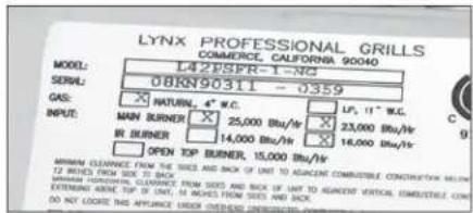
• Proof of purchase by the original owner - Serial number.
The serial number can be located on the rating plate which is located either on the underside of the drip tray, on the heat shield behind the front panel).
For warranty service, contact the Lynx Customer Care Department for an authorized service agent near you at:
• (888) 289-5969
- www.lynxgrills.com

text_image
LYNX PROFESSIONAL GRILLS COMMERCE, CALIFORNIA 90040 MODEL: L42PSFR-1-NG SERIAL: 08KN90311 - 0359 CAS: ✗ NATURAL, 4" W.C. □ LP, 11" W.C. INPUT: MAIN BURNER ✗ 05'W.C.Your satisfaction is of the utmost importance to us. If a problem cannot be resolved to your satisfaction, please write, fax or email us:
Lynx Professional Grills
7300 Flores Street, Downey, CA 90242
Service: (888) 289-5969
Tel: (562) 299-6900
Fax: (562) 299-6978
www.lynxgrills.com
Contact Lynx Customer Care for replacement parts. Parts are shipped F.O.B. Commerce, CA.
I. Limited Lifetime Warranty
The stainless steel grill body, ProSear™ burner and rotisserie infrared burner are warranted to be free from defects in material and workmanship when subjected to normal domestic use and service for the lifetime of the original purchaser. The tubular stainless steel main burners carry a limited twelve (12) year warranty. This warranty excludes surface corrosion, scratches, and discoloration which may occur during normal use. This warranty is limited to the replacement of the defective parts, with the owner paying all other cost including labor, shipping and handling.
II. Limited Five-Year Warranty
The following grill parts are warranted to be free from defects in material and workmanship, when subjected to normal domestic use and service, for a period of five (5) years from the original date of purchase; cooking grates, warming racks, spit rods, briquette trays, manifolds and gas valves. This warranty is limited to the replacement of the defective parts, with the owner paying all other costs including labor, shipping, and handling.
III. Limited Two-Year Warranty
All other grill components are warranted to be free from defects in material and workmanship, when subjected to normal domestic use and service, for a period of two (2) years from the original date of purchase. This warranty is limited to the replacement of the defective parts, with the owner paying all other costs including labor, shipping and handling.
IV. Limited One-Year Warranty.
For a period of one (1) year from the original date of purchase, Lynx will replace or repair parts found to be defective at no cost to the original purchaser. This includes the cost of shipping replacement parts and, where necessary, service labor at prevailing local rates by a Lynx authorized service person. Service will be provided during normal business hours and must be authorized in advance by Lynx.
V. Limitations & Exclusions
1) This Warranty shall apply to products purchased and located in the United States and Canada. Products must be purchased in the country where service is requested.
2) Warranty applies only to the original purchaser and may not be transferred.
3) Warranty is in lieu of all other warranties expressed or implied and all other obligations or liabilities related to the sale or use of its grill products.
4) Warranty shall not apply and Lynx is not responsible for damage resulting from misuse, abuse, alteration of or tampering with the appliance, accident, hostile environ-
ment, flare-up fires, improper installation, or installation not in accordance with the instructions contained in this manual, or the local codes.
5) Lynx shall not be liable for incidental, consequential, special or contingent damages resulting from its breach of this written warranty or any implied warranty.
6) Some states do not allow limitations on how long an implied warranty lasts, or the exclusions of or limitations on consequential damages. This warranty gives you specific legal rights and you may have other rights which vary from state to state.
7) No one has the authority to add to or vary Lynx's warranty, or to create for Lynx any other obligation or liability in connection with the sale or use of its products.
8) Limited to the replacement of defective parts with the owner paying all other costs including labor.
VI. What is not covered: Lynx shall not be responsible for and shall not pay for the following
1) Installation or start-up, damages or problems caused by improper installation or use;
2) Service by an unauthorized service provider;
3) Damage or repair due to service by an unauthorized service provider or use of unauthorized parts;
4) Warranty does not apply to products installed in any commercial or non-residential application. Examples of excluded applications include, but are not limited to day care centers, schools, bed and breakfast centers, churches, private clubs, fire stations, club houses, common areas in multi-family dwellings, restaurants, hotels, nursing homes, food service locations and institutional food service locations.
5) To correct normal adjustments or settings, due to improper installation, commissioning or local gas supply properties.
6) Shipping and handling costs, export duties, installation, removal, or re-installation cost.
7) Display models are sold "as is". If you have purchased a display model, please be advised that it is sold "as is" and that it is subject to the following warranty exclusions: any exterior or cosmetic damage is nonwarrantable; any missing components will be replaced at consumers expense; major handling damage to manifold, valve and ignition system will be serviced at consumer's expense; all other warranty's (standard warranty) will remain in effect.
8) The cost of a service call to diagnose trouble.
INSTALLATION GUIDELINES
INSTALLATION GUIDELINES 22
Before You Start 22
If shipment arrives damaged 22
Built-In Installations 22
Clearance to Combustibles 23
Cut Out Dimensions 24
Unpacking and Assembly 25
Gas Connections 26
Natural Gas 26
LP Gas 27
Gas Line Purging 28
Gas Conversion Kits 28
Electrical Connections 29
Connection to AC 29
Battery Installation 29
Final Checks 30
Leak Testing 30
Wiring Schematics 32
L400/L500 Non-Rotisserie Grill 32
L400/L500 Rotisserie Grill 33
L600/L700 Non-Rotisserie Grill 34
L600/L700 Rotisserie Grill 35
Sedona Grill Exploded Parts View 36
Sedona Grill Parts List 37
Model Specific BTU Outputs 38
Maximum Runs for All Appliances on Supply Line 38

WARNING
- Always maintain the required clearances from combustible construction as detailed. The grill is designed for outdoor use only. NEVER use in a garage, building, shed, breezeway or other enclosed area. This grill shall not be used under any overhead combustible construction.
- Gas grills are not design certified for and are not to be installed in or on recreational vehicles, portable trailers, boats or any other moving installation.
- Keep any electrical supply cord and the fuel supply hose away from any heated surfaces. Electrical cords should be placed away from walkways to avoid creating a tripping hazard.
- Do not repair or replace any part of the grill unless specifically recommended in this manual. Other service should be performed by a qualified technician.
- All gas lines must have a shut-off that is readily and easily accessible. Be sure the owner knows where the shut-off is located. If you smell gas, check for gas leaks immediately. Check only with a soap and water solution. Never check for gas leaks with an open flame. (See INDEX: "Leak Testing" for further details.)

WARNING
- The outdoor cooking gas appliance and its individual shutoff valve must be disconnected from the gas supply piping system during any pressure testing of that system at test pressures in excess of 0.5 psi (3.5 kPa).
- The outdoor cooking gas appliance must be isolated from the gas supply piping system by closing its individual manual shutoff valve during any pressure testing of the gas supply piping system at test pressures equal to or less than 1/2 psi (3.5 kPa).

STATE OF MASSACHUSETTS
- Massachusetts requires all gas be installed using a plumber or gas fitter carrying the appropriate Massachusetts license.
- All permanently-installed natural gas or propane installations require a "T" handle type manual gas valve be installed in the gas supply line to this appliance.
- This does not apply to portable propane installations using a 20 pound cylinder.
BEFORE YOU START
IF SHIPMENT ARRIVES DAMAGED
VISIBLE LOSS OR DAMAGE
Be certain any visible damage to the carton is noted on freight bill or express receipt and signed by the person making delivery.
FILE CLAIM FOR DAMAGES IMMEDIATELY, regardless of extent of damage.
How long is your run?
Keep all gas supply lines as short as possible because gas lines lose pressure over distance and with each elbow and tee that is added. This drop in pressure affects grill performance. (See INDEX: "Gas Supply Line Runs" for further details.)
Are you "on-the-level"?

WARNING
- Never install this product into a combustible enclosure without an insulated jacket. Doing so could result in fire, property damage and personal injury.
- Never locate the grill under a roof or overhang, in a building, garage, shed or other such enclosed area.
- Never locate the grill under combustible construction.
- Installation must conform with local codes or, in the absence of local codes, with either the National Fuel Gas Code, ANSI Z223.1/NFPA 54, Natural Gas and propane Installation Code, CSA B149.1, or Propane Storage and Handling Code, B149.2,
CONCEALED LOSS OR DAMAGE
If damage is unnoticed until the grill is unpacked, notify the transportation company or carrier immediately and file a "concealed damage" claim with them. This should be done within (15) days of the date delivery is made to you. Be sure to hold on to the container for inspection. We cannot assume responsibility for damage or loss incurred in transit. (See IN-DEX: "Contacting Lynx Customer Care" for further details.)
IMPORTANT NOTES
Where's the Wind?
When selecting a suitable location, consider important factors such as exposure to the wind and foot-traffic patterns.
If you have a freestanding grill, position it so the prevailing wind blows into the front control panel (at your back when

natural_image
Mechanical assembly diagram showing a multi-layered conveyor belt system with directional arrows (no text or symbols)Be sure wind doesn't blow into the hood gap.
grilling), supporting the proper front-to-rear airflow.
Built-in grills lo- cated in areas with
prevailing winds should be protected by a wind barrier.
Winds hitting the back of the grill directly may cause problems, as well as wind blowing along the hood gap.
Proper leveling during installation is critical. A grill that is out of level will cause erratic burner combustion and inefficient, uneven heating. A carpenter's spirit level should be used to level the grill both front-to-back and side-to-side.
If the floor is uneven or has a decided slope, re-leveling may be required each time you move a freestanding unit.
BUILT-IN INSTALLATIONS
Built-in grills are designed for easy installation into masonry enclosures.
NOTE:
Built-in grills are intended either for installation in a built-in enclosure constructed of non-combustible materials or for an installation in a built-in enclosure constructed of combustible material when installed with an insulating jacket.
For non-combustible applications, the grill drops into the opening shown in the cutout detail drawing (See INDEX: "Gas Requirements") and hangs from its counter-top trim. A deck is not required to support it from the bottom.
When using the insulated jacket in a combustible enclosure, the jacket must be supported from the bottom by a ledge on each side or a full deck beneath the jacket.
(See INDEX: "Gas Requirements") Pay special attention to the provisions shown for gas line hook-up.

CAUTION
When using a Lynx Quick Disconnect device (LQD) and a Lynx Insulating Jacket the flexible hose must not contact any portion of the firebox section of the grill. It is recommended that the installer use best fitting practices to hard pipe the connection outside of the insulating jacket through one of the openings in the insulating jacket. This will locate the hose outside of the unit and prevent contact with hot surfaces. Overheating the LQD hose can cause separation and gas leaks that pose a potential fire hazard.
The enclosure should have ventilation holes to prevent gas build-up in the event of a leak. The deck ledges and counter should be flat and level. (refer to ANSI Z21.58 Standard for Outdoor Cooking Gas Appliances, Section 1.7 Enclosures For Self Contained LP-Gas Supply Systems)
This grill requires that a 120 volt, 60 hertz, 15 amp GFI certified outlet be installed by a qualified electrician.
CLEARANCE TO COMBUSTIBLES
Minimum clearance from the sides and back of the grill to adjacent combustible construction below the counter top surface are 12" from the sides and back.
Minimum clearance from the sides and back of the grill to adjacent combustible construction extending above the counter top surface are 18" from the sides and back.
Do not use this appliance under overhead combustible surfaces.
A minimum of 6" of clearance is needed on the left side of
the grill above the counter top for the motor and skewer.
If the grill is to be placed in a combustible enclosure an approved insulating jacket is necessary. Order model number LIJ400, LIJ500, LIJ600 or LIJ700 depending on your grill size.
REAR HOOD CLEARANCE
A 3" clearance is required behind the grill to allow the front hood to open.
The grill exhausts combustion products and cooking greases to the back. Never locate the grill where this exhaust will be difficult to clean.
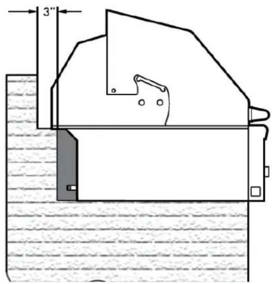
text_image
3"CUT-OUT DIMENSIONS FOR BUILT-IN GRILLS
Note: Side burners may be rotated 90 degrees.
Note: For Natural Gas grills, the manufacturer recommends using 3/4" gas supply lines.
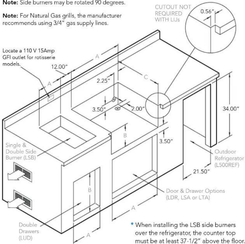
text_image
Note: Side burners may be rotated 90 degrees. Note: For Natural Gas grills, the manufacturer recommends using 3/4" gas supply lines. Locate a 110 V 15Amp GFI outlet for rotisserie models. Single & Double Side Burner (LSB) Double Drawers (LUD) CUTOUT NOT REQUIRED WITH LIJs 0.56" 2.25" 3.50" 2.00" 3.50" 34.00" Outdoor Refrigerator (L500REF) 21.50" Door & Drawer Options (LDR, LSA or LTA) * When installing the LSB side burners over the refrigerator, the counter top must be at least 37-1/2" above the floor.COUNTERTOP NOTCH DETAIL
Only required if island countertop overhangs the face of the island
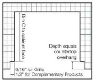
text_image
Dim C to cabinet face Depth equals countertop overhang 9/16" for Grills — 1/2" for Complementary ProductsINSULATING JACKET
NOTE: Insulating jacket required for all grills installed into a combustible enclosure.

text_image
A 5" 4.5" B C 3"BUILT-IN GRILL
| Model | A | B | C | ||
| L400 | 23.00 | 10.00 | 21.25 | ||
| L500 | 29.00 | 10.00 | 21.25 | ||
| L600 | 35.00 | 10.00 | 21.25 | ||
| L700 | 41.00 | 10.00 | 21.25 |
BUILT-IN GRILL W/ INSULATING JACKET
| Model | A | B | C | ||
| LIJ400 | 30.00 | 11.62 | 23.25 | ||
| LIJ500 | 36.00 | 11.62 | 23.25 | ||
| LIJ600 | 42.00 | 11.62 | 23.25 | ||
| LIJ700 | 48.00 | 11.62 | 23.25 |
COMPLEMENTARY PRODUCTS
| Model | A | B | C | ||
| LSB501 | 11.00 | 4.00 | 16.00 | ||
| LSB502 | 21.00 | 4.00 | 16.00 | ||
| LDR424 | 22.00 | 19.00 | - | ||
| LDR530 | 28.25 | 19.00 | - | ||
| LDR636 | 33.75 | 19.00 | - | ||
| LSA530 | 28.25 | 19.00 | 20.00 | ||
| LSA636 | 33.75 | 19.00 | 20.00 | ||
| LUD517 | 17.25 | 12.75 | 20.00 | ||
| L500REF | 21.50 | 34.00 | 24.50 |
An enclosure for an LP-gas cylinder shall be ventilated by openings at both the upper and lower levels of the enclosure. The effectiveness of the opening(s) for purposes of ventilation shall be determined with the LP-gas supply cylinder in place. This shall be accompanied by one of the following:
a) One side of the enclosure shall be completely open; or
b) For an enclosure having four sides, a top and a bottom:
- At least two ventilation openings shall be provided in the side walls of the enclosure, located within 5 in (217 mm) of the top of the enclosure, equally sized, spaced at a minimum of 90 degrees (1.57 rad), and unobstructed. The opening(s) shall have a total free area of not less than 1 in 2/ lb (14.2 cm2/kg) of stored fuel capacity.
- Ventilation opening(s) shall be provided at floor level of the enclosure and shall have a total free area of not less than 1/2 in 2/lb (7.1 cm2/kg) of stored fuel capacity. If ventilation openings at floor level are in a side wall, there shall be at least two openings. The bottom of the openings shall be 1 in (25.4 mm) or less from the floor level and the upper edge no more than 5 in (127 mm) above the floor level. The openings shall be equally sized, spaced at a minimum of 90 degrees (1.57 rad) and unobstructed.
- Every opening shall have minimum dimensions so as to permit the entrance of a 1/8 in (3.2 mm) diameter rod.
- Ventilation openings in side walls shall not communicate directly with other enclosures of the outdoor cooking gas appliance.
Keep the ventilation openings of the cylinder enclosure free and clear from debris.
UNPACKING AND ASSEMBLY
By carefully following the uncrating and unpacking steps, you will improve the customer's first experience.

WARNING
EXCESSIVE WEIGHT HAZARD!
Use two or more people to move or install this unit. Failure to follow this instruction can result in back or other personal injuries.
CRATE & CARTON
HOW TO REMOVE THE CARTON
- Cut the main strap holding the grill to the pallet.
- Remove the straps at the bottom of the carton.
- Lift off the carton.
- With assistance, remove the grill from the pallet and place into desired location.
INTERIOR PACKING
Sturdy zip-ties and straps are used to ensure your grill arrives at your home in the same condition that it left our factory. BE SURE YOU HAVE REMOVED ALL ZIP-TIES BEFORE USING YOUR GRILL.
- Remove the white accessory box and packing, the grill racks, and remove any loose items from the firebox.
- Carefully cut the zip-ties securing the warming rack and rotisserie spit (if equipped).
Make sure you remember to remove the zip-ties on the burners
- On ProSear™ models, cut and remove zip-ties from the burner partition on the left side of the ProSear™ burner.
- Ensure that all burners are properly seated on the burner valve orifice and sitting level with the legs in the frame slots and no side-to-side movement.
natural_image
Close-up of a metallic mechanical component with two U-shaped cutouts and a small rectangular slot (no visible text or symbols)
natural_image
Close-up of a metallic pipe or duct assembly with bolted joints and dashed lines indicating material (no text or symbols visible)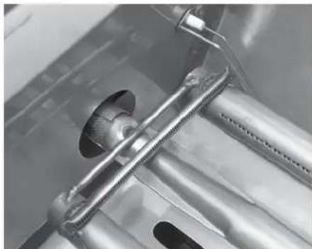
natural_image
Close-up of a metallic mechanical component with threaded shaft and mounting bracket (no visible text or symbols)
natural_image
Close-up of a metallic heating element with cooling fins and mounting brackets (no visible text or symbols)GAS CONNECTIONS

WARNING
Never connect a gas line directly to the grill. A pressure regulator must be installed on all gas equipment. All local codes require it and Lynx supplies the correct regulator with your grill. Removing or failing to install the pressure regulator can result in fire and serious personal injury and will void the warranty.
The grill is factory set to use either propane (LP) or natural gas (NAT). It is critical that the gas you use matches that which the grill was set up for.
text_image
LYNX PROFESSIONAL GRILLS COMMERCE, CALIFORNIA 90040 MODEL: L42ESFR-1-NC SERIAL: 08RN90311 - 0359 GAS: HATURIN, 4" W.C. LP, 11" W.C. MAIN BURNER 25,000 Btu/hr 23,000 Btu/hr IN BURNER 14,000 Btu/hr 16,000 Btu/hr OPEN TOP BURNER, 15,000 Btu/hr MINIMUM CLEVERAGE FROM THE SIDES AND BACK OF UNIT TO ADJAMINE COMBUSTIBLE CONSTRUCTION BELOW 12 INCHES FROM SIDE IT BACK MINIMUM HORIZONTAL CLEVERAGE FROM SIDES AND BACK OF UNIT TO ADJAMINE VERTICAL DIMESTURE COM- INTENSING ARENE TOP OF UNIT, 5 INCHES FROM SIDE IT BACK. DO NOT COORE THIS APPLIANCE UNDER OVERHEAD DIMESTURE OR CThe Rating plate lists serial numbers, model numbers and gas type. This one is undemeath the drip tray.
You can verify that by checking the rating plate.
The rating plate is located in one or more of the following places:
- Attached to the underside of the drip tray
- On the heat shield behind the front panel
Ensure that the gas supplied meets with the minimum pressure requirements. Do not operate the grill on any gas other than that for which the grill has been set.
| Fuel WC Max Inlet | WC Min Under Full | Load |
| Nat Gas 7 in 4 in | ||
| LP 14 in 11 in |
Water Column Requirements
Both the regulator and the manifold orifices have been tuned for the type of gas specified on the rating plate.
All installation and all installation parts must conform to local codes with the National Electrical Code, ANSI Z223.1/NFPA 70 latest edition and the National Fuel Gas Code, ANSI Z223.1/NFPA 54 in the U.S and CGA-B149.1/.2 in Canada.
Canadian installations must conform to CGA-B149.1/.2 natural gas/propane installation code. (Canada)
NATURAL GAS
It is recommended that only qualified professionals perform the required plumbing on this product.
To ensure satisfactory performance, the gas supply line
NATURAL GAS HOOK-UP
3 Typical Natural Gas Installations

text_image
GAS HOOK-UP Natural Gas BOT 2 Typ Install (GRILL ISLAND) SUPPLIER STREET ELIND SUPPLIES 1" FITTING (SLEAR TEST) SUPPLIER 5" NAPPLE SUPPLIES NATURAL GAS REGULATOR: PRE-LET AT 4" N- (SLEAR TEST) INSTALLER SUPPLIER GAS SHUT-OFF VALVE ORST BE IN ACCESSIBLE LOCATION (SLEAR TEST) TYPICAL BOTTOM CONNECTION TYPICAL BACK OF GRILL CONNECTION EXTRA LIF/2 COPIER RED HELF (SLEAR TEST) EXTRA PIPE ROOT HERE SUPPLIER NATIONAL GAS REGULATOR: PRE-LET AT 4" N- (SLEAR TEST) INSTALLER SUPPLIER GAS SHUT-OFF VALVE ORST BE IN ACCESSIBLE LOCATION (SLEAR TEST) EXTRA PIPE ROOT HERE SUPPLIER SWEET ELIND SUPPLIER NATIONAL GAS REGULATOR: PRE-LET AT 4" N- (SLEAR TEST) TYPICAL BACK OF ISLAND CONNECTION GRILL ISLANDBOTTLED LP HOOK-UP
2 Typical LP Bottle Installations

text_image
D LP HOOK-UP LP Bottle ns ALTERNATE LOCATION SUPPLIES LP BRASS FITTING CLEAR (EST) TYPICAL BACK OF GRILL CONNECTION SUPPLIES LP MODE WITH REGULATOR (CLEAR (EST)) TYPICAL BOTTCH CONNECTION GRILL ISLAND IF NO. 100 YEAR CLEARANCE CONSOLTD FOR 1000 HOTATION TANK GRILL ISLANDmust be sized to accommodate the total BTU requirements of all the gas-fired equipment that will be connected to that line.
In no case should pipe less than 34 " inside diameter or 1" outside diameter ever be used to connect this product.
- Calculate the total BTU output of all equipment and refer to "INDEX: Gas Supply Line Runs" for allowable run distances for 34 inch pipe. Failure to meet these minimum requirements may reduce performance of the grill and any other appliances running on that supply line.
- Always keep supply line runs as short as possible. (See INDEX: "BTU Output" for specific model outputs)
- A gas shut-off valve must be installed in an easily accessible location by a qualified plumber.
- Keep threading compound off of the first two pipe threads to avoid having any small pieces of compound break loose and clog a burner valve or orifice. Do not use threading compound on any flare fittings.
For built-in installations, it is recommended that any flexible
Keep last two threads clean
natural_image
Close-up of a metallic mechanical connector with a black arrow pointing to a feature (no text or symbols visible)pipe used be kept as short as possible. (See INDEX: "Gas Connections" for typical permanent hook up.)
For freestanding units using natural gas, it is strongly recommended to use a quick disconnect kit.
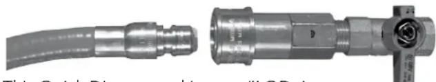
natural_image
Two metallic industrial hoses with connectors, one showing a coiled cable and the other a valve assembly (no visible text or symbols)This Quick Disconnect kit, part #LQD, is available from the manufacturer.
LP GAS
Grills set up for LP gas come equipped with an LP hose/regulator assembly for connection to a standard 20 lb. LP cylinder. (Type 1). All fittings necessary to attach the assembly to the grill are included.
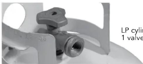
natural_image
Close-up of a mechanical valve component with no visible text or symbols on the device itself.LP cylinder with type 1 valve connection
HARD PIPED LP FROM BULK STORAGE TANKS
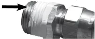
Permanently plumbed LP connections, such as those in line with a bulk cylinder, require a 4/11 regulator. (Lynx P/N 30781)
When using the 4/11 regulator you must ensure that it is set for the proper fuel type. This is done by removing the regulator cap and gasket and looking at the bottom of the plunger to see what fuel type is visible. This is the regulator fuel setting. NAT is for natural gas and LP is for propane gas. The LP setting can be further identified by the large diameter disk on the bottom of the plunger. To change from one gas to the other simply push the plunger to the side to snap it out of the cap, turn the plunger so it reads the desired gas type on the bottom, and push the plunger until it snaps back into place in the cap then replace the cap into the regulator.
Never connect an unregulated gas line to the grill.
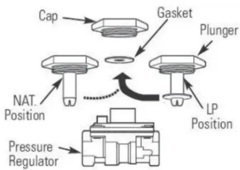
flowchart
graph TD
    A["Cap"] --> B["Gasket"]
    B --> C["Plunger"]
    C --> D["LP Position"]
    D --> E["NAT. Position"]
    E --> F["Pressure Regulator"]
    F --> G["End"]

WARNING
DO NOT CHANGE THE REGULATOR/HOSE ASSEMBLY OR USE ANY OTHER ASSEMBLY THAN THE ONE SUPPLIED WITH YOUR GRILL.
DO NOT ATTEMPT TO USE A 5LP-A EQUIPPED REGULATOR/HOSE ASSEMBLY WITH A STANDARD 510 POL CYLINDER/VALVE ASSEMBLY.
DO NOT STORE A SPARE LP-GAS CYLINDER UNDER OR NEAR THIS APPLIANCE
NEVER FILL THE CYLINDER BEYOND 80 PERCENT FULL.
IF THE INFORMATION ABOVE IS NOT FOLLOWED EXACTLY, A FIRE CAUSING DEATH OR SERIOUS INJURY MAY OCCUR.
GAS CONNECTIONS... continued
LP Cylinder Requirements
The LP cylinder must be constructed and marked in accordance with the specifications for LP gas cylinders of the U.S. Department of Transportation (DOT) and designed for use with a Type 1 system only.

text_image
Cylinder Retention DeviceCylinders of free standing grills must be secured using the provided cylinder retention system to avoid accidental movement.
When exchanging
your cylinder for a refill, exchange only for a Type 1 20lb cylinder with an over-fill protection device.
Never use a cylinder with a damaged valve.
A dented or rusty LP cylinder may be hazardous and should be avoided. If in doubt, have it checked by your LP supplier.
Always check for leaks after every LP cylinder change. (See INDEX: "Leak Test" for further details.)
Always shut off the LP-gas supply at the cylinder when the grill is not in use.
Cylinders must be stored outdoors in a well-ventilated area out of the reach of children. If your grill is stored indoors, the LP cylinder must be stored outside.
Place a dust cap on the cylinder valve outlet whenever the cylinder is not in use. Only install the type of dust cap on the cylinder valve outlet that is provided with the cylinder valve. Other types of caps or plugs may result in leakage of propane.
LP Connections
Make sure the LP cylinder valve is fully closed. It is possible for the valve to be open without releasing gas but, as soon as you start connecting the regulator, gas will leak from the connection.
Insert the regulator inlet into the cylinder valve and turn the black coupler clockwise until the coupler is hand tight. Do not over-tighten this connection.
To disconnect the coupler, first make sure the main cylinder valve is turned off. Grasp the coupler and turn counter clockwise. The inlet will then disengage.
Always leak-test the connection after refilling or exchanging LP cylinders. (See INDEX: "Leak Test" for further details.)
GAS LINE PURGING
You should purge the gas line of air before attempting to light the grill.
Make sure all grill controls are in the "OFF" position.
Slowly turn on the main gas supply.
Push in the left burner knob and confirm that the igniter is sparking. It is furthest from the fuel source and will completely purge the lines. It will take several seconds for the burner to light.
Hold the knob ON for about 20 seconds to allow the air in the system to purge and the burner to light
Wait at least 5 minutes after shutting off the control before attempting to light the burners.
GAS CONVERSION KITS
Gas conversion kits are available from Lynx Grills the grill to operate on either Natural gas (SEDNGK) or LPG (SEDLPK). These kits should be installed by a qualified technician.
The kits come with complete installation instructions. These instructions should be read completely and fully understood before installing the conversion kit.

WARNING - ELECTRICAL GROUNDING
Product installation must meet local electric codes or, in the absence of local codes, the latest edition of the National Electrical Code ANSI/NFPA No. 70 or the Canadian Electrical Code CGA 1.6b2005.
Use only a Ground Fault Interrupter (GFI) protected circuit with this outdoor cooking gas appliance.
Important: When connecting the rotisserie motor, first connect the motor to the grill and then plug the grill into the outlet.
This grill and rotisserie are equipped with a three prong (grounding) electric plug for your protection against shock hazard and must be plugged directly into a properly grounded three prong outlet. Never cut or remove the grounding prong from this plug.
Use only extension cords with a 3 prong grounding plug, rated for the power of the equipment, and approved for outdoor use with a "W-A" marking.
To protect against electric shock, do not immerse any part of the power cord, an extension cord or any plugs in water or other liquid.
Unplug the product from the outlet when not in use and before cleaning. Allow it to cool before putting on or taking off parts.
Remove the rotisserie motor when not in use and store in a dry location.
Do not let the cord hang over the edge of a table or touch hot surfaces.
Do not use an outdoor cooking gas appliance for purposes other than intended.
Do not operate any outdoor cooking gas appliance with a damaged cord, plug, or after the appliance malfunctions or has been damaged in any manner. Contact the manufacturer for repair.
CONNECTION TO AC
Installation requires an outdoor 120VAC 15A GFI (Ground Fault Interrupter) electrical outlet adjacent to the grill.
The GFI outlet features an internal breaker that reduces shock hazard. This type of outlet should be installed by a qualified electrician either inside the island enclosure for built-in units, or near the location where a free-standing unit will be used.
For built in grills, the supplied 12 VDC transformer should be installed below the grill within the cabinet enclosure. Select a location where the transformer is protected against water, heat and physical damage.
When installing the transformer to the grill be careful to prevent the wiring and transformer from contacting any hot surfaces behind or below the grill. It is recommended that the transformer be located below the grill in a readily accessible location. Be sure to provide adequate access to facilitate service if the transformer or connections should need future maintenance.
If the electrical system fails to operate, a connection may have come loose in shipping or the GFI may have tripped, requiring a reset. See the Troubleshooting section for more details.
BATTERY INSTALLATION
Your grill includes a standard 9V battery that provides backup power for the electronic ignition system. To install or replace the battery, follow this procedure:
- Locate the battery compartment on the inside rear wall of the cart, or inside the built-in enclosure. The cart has an access panel on the back side that allows easy access to the battery holder.
- Disengage the battery compartment by pushing the battery cover in the direction indicated by the arrow on the cover.
- The battery compartment will disengage and protrude so that you may pull and remove the battery and compartment.
- Insert and/or replace a new 9V battery into the battery compartment.
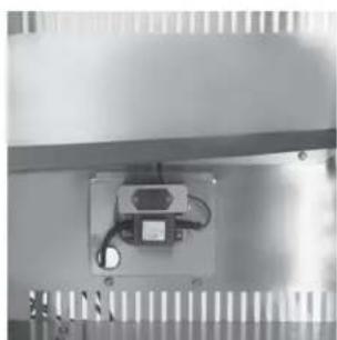
natural_image
Close-up of a metallic electronic device mounted on a slatted base, with visible wiring and a small component (no text or symbols)- Locate the battery compartment 3. The battery compartment will disengage and protrude

natural_image
Close-up of an electrical component with wires and a small display (no visible text or symbols)
natural_image
Close-up of a hand holding a small electronic component with wires, no visible text or symbols- Insert and/or replace a new 9V battery
LEAK TESTING

DANGER
TO PREVENT FIRE OR EXPLOSION HAZARD, DO NOT SMOKE OR ALLOW ANY POTENTIAL SOURCE OF IGNITION (SPARKS, ELECTRICAL ARCING, ETC) IN THE AREA WHILE PERFORMING A LEAK TEST. LEAK TESTS SHOULD BE CONDUCTED OUTDOORS ONLY. NEVER CONDUCT A LEAK TEST USING FIRE OR FLAME.
Leak Test Procedure:
- Create a soapy solution of 1 part soap and 3 parts water.
- Confirm that all control knobs are in the off position.
- Turn on the fuel supply. For natural gas, turn the valve handle 1/4 turn to align with the gas flow.
- For L.P., turn the cylinder valve knob counter clockwise one full rotation.
- Apply the soap solution generously by paint brush or squirt bottle on all connections and fittings.
- If bubbles appear to "grow" on any of the connections, you have a gas leak. IMMEDIATELY turn off the gas supply.
Fixing a Gas Leak
- Shut off the gas supply
- Turn all grill controls to the "ON" position to purge the grill of any gas build-up, then turn the controls back "OFF".
- Wash off the soapy solution with cold water and dry.
- Tighten the loose joint, or replace the faulty part with manufacturer-recommended replacement parts.
- DO NOT attempt to repair the L.P. cylinder valve if it is damaged. The only way to safely resolve a damaged cylinder is to REPLACE IT.
- Repeat the leak test to ensure that no leaks are present.
LOW HEAT BURNER ADJUSTMENT
FOR MAIN STAINLESS STEEL AND PROSEARTM BURNERS ONLY!
DO NOT ADJUST THE ROTISSERIE BURNER.
The main burners and side burners on your grill feature an adjustable low setting.
Fluctuations in gas pressure, gas conversion and even in the quality of the gas itself may affect burner performance at the "LOW" setting. It could be either too high or too low.
To adjust the burner low setting:
• Make sure the grill is cool.
- Remove the cooking grates and briquette trays so you can see the flames while adjusting the burners.
• Light the burner and allow it to preheat on high for 3 minutes.
- Turn the burner to "LO".
- Pull off the control knob.
- While holding the valve shaft with pliers as shown insert a small flat screwdriver into the center shaft and adjust the flame's low setting.
The proper setting is where the flame is stable at its lowest setting. A slight flutter will be present in the crossover portion of the front of the burner before the burner itself becomes weak.
The factory setting for propane gas is 12 to 34 turn from the very bottom of the adjustment. The setting for natural gas is 1-12 to 1-34 from the bottom. After the low settings are proper, turn all burners to high for visual inspection.
BURNER FLAME/AIR SHUTTER ADJUSTMENT
The amount of air that enters a burner is controlled by the air shutter.
Each grill burner is tested and adjusted at the factory prior to shipment. However, fluctuations in gas pressure, gas conversion and even in the quality of the gas itself may make it necessary to adjust the burner.
The flames of the main burners should be visually checked.
Flames should be blue and stable with slight yellow tips. The bright-blue core should be about 3/8 inch high with a total flame height of about 1 1/2 inches.
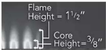
text_image
Flame Height = 1½" Core Height = 3/8"The flames should burn quietly. (no "torch" sounds) and they should not "lift" up from the burner.
If your flames do not match those indicated in the photo, ensure that the air shutter and burner ports are free and

natural_image
Close-up of a mechanical assembly with a metallic component and internal components (no visible text or symbols)Clockwise will lower the flame setting, counterclockwise will raise it.
FINAL CHECKS
clear of dirt, debris, or spider webs. If clear, then adjust the air shutter.
It is locked in place by a screw which must be loosened before adjusting. Once adjusted retighten the screw.
TO ADJUST:

DANGER
BE EXTREMELY CAREFUL AROUND HOT BURNERS AND OTHER GRILL PARTS.
- Remove the racks and briquette trays.
- Remove the hex head bolt securing the burners.
- Lift out the burner, loosen the set screw and then put the burner back in place and light it.
- If the flame is excessively yellow, indicating insufficient air, CAREFULLY turn the air shutter counterclockwise to allow more air to the burner.
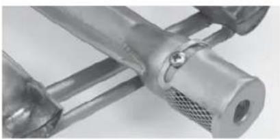
natural_image
Close-up of a metallic mechanical component with no visible text or symbols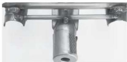
natural_image
Close-up of a mechanical component with a cylindrical shaft and flange (no visible text or symbols)- If the flame is noisy (sounds like a torch) and tends to lift away from the burner, indicating too much air, turn the air shutter clockwise.
• After the burner cools down, remove it, tighten the air shutter set screw and reinstall the burner, briquette trays and grill racks.
NOTE: The ProSear™ does not have an air shutter.
- The appearance of the ProSear™ burner should be visually checked. The ceramic tiles should be uniformly red to orange in appearance. There should be no lifting, fluttering or lazy blue flames. Some food particles will show as yellow flames but should burn off.
natural_image
Exterior view of a rectangular metal grate with vertical slats and a small outlet (no text or symbols)ONE LAST THING
Finally, before leaving, check all the burners for proper operation. Make sure the control knobs turn freely and completely through their full range.
IMPORTANT:
Make sure the owner knows where the main gas supply shut off valve is located.
Finally, for safety and for proper use & care, you must leave this manual with the owner. Make sure you advise them to keep it for future reference.
For technical assistance call:
Lynx Customer Care
888-289-5969
L400/L500 NON-ROTISSERIE GRILL

flowchart
graph TD
    A["HALOGEN LIGHTS 80446"] --> B["4X Molex Male Female pins"]
    B --> C["TRANSFORMER 33525"]
    C --> D["BACK OF THE GRILL FRONT OF THE GRILL"]
    D --> E["Molex Female Male Pins"]
    E --> F["80650"]
    E --> G["Light Switch"]
    H["LED Light"] --> I["LED Light"]
    I --> J["31161"]
    J --> K["31254 Igniter (16)"]
    K --> L["31255 Igniter (25)"]
    L --> M["80473"]
    N["ORANGE"] --> O["Black"]
    N --> P["Red"]
    N --> Q["Orange"]
    R["Molex Female Male Pins"] --> S["Molex Male Female Pins"]
    S --> T["80648"]
    U["Green Varistor"] --> V["Molex Female Male Pins"]
    V --> W["31161"]
    X["Back of the grill 80614"] --> Y["31254 Igniter (16)"]
    Y --> Z["31255 Igniter (25)"]
L400/L500 ROTISSERIE GRILL
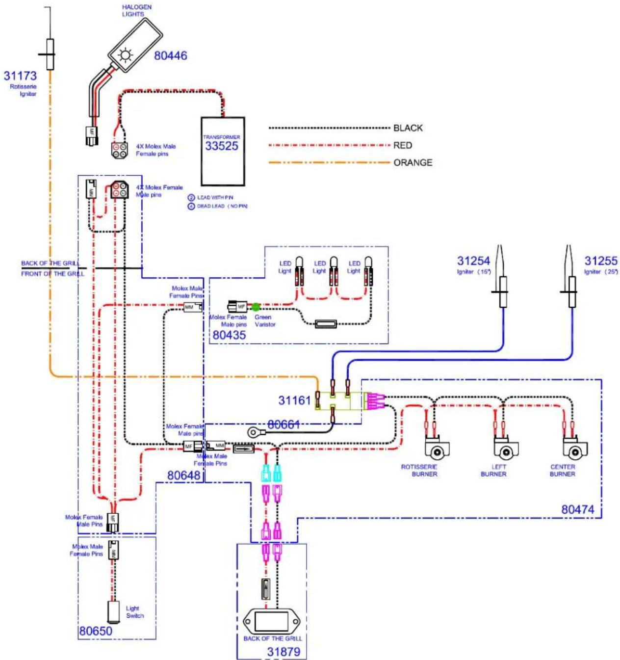
flowchart
graph TD
    A["31173 Rotisserie Igniter"] --> B["80446 HALOGEN LIGHTS"]
    B --> C["4X Molex Male Female pins"]
    C --> D["TRANSFORMER 33525"]
    D --> E["80435 Molex Female Male pins"]
    E --> F["LED Light"]
    E --> G["LED Light"]
    E --> H["LED Light"]
    E --> I["Green Varistor"]
    E --> J["Molex Female Male pins"]
    E --> K["Molex Female Male Pins"]
    E --> L["Molex Male Female Pins"]
    E --> M["Molex Male Female Pins"]
    E --> N["Molex Female Male Pins"]
    E --> O["Molex Female Male Pins"]
    E --> P["Molex Female Male Pins"]
    E --> Q["Molex Female Male Pins"]
    E --> R["Molex Female Male Pins"]
    E --> S["Molex Female Male Pins"]
    E --> T["Molex Female Male Pins"]
    E --> U["Molex Female Male Pins"]
    E --> V["Molex Female Male Pins"]
    E --> W["Molex Female Male Pins"]
    E --> X["Molex Female Male Pins"]
    E --> Y["Molex Female Male Pins"]
    E --> Z["Molex Female Male Pins"]
    E --> AA["Molex Female Male Pins"]
    E --> AB["Molex Female Male Pins"]
    E --> AC["Molex Female Male Pins"]
    E --> AD["Molex Female Male Pins"]
    E --> AE["Molex Female Male Pins"]
    E --> AF["Molex Female Male Pins"]
    E --> AG["Molex Female Male Pins"]
    E --> AH["Molex Female Male Pins"]
    E --> AI["Molex Female Male Pins"]
    E --> AJ["Molex Female Male Pins"]
    E --> AK["Molex Female Male Pins"]
    E --> AL["Molex Female Male Pins"]
    E --> AM["Molex Female Male Pins"]
    E --> AN["Molex Female Male Pins"]
    E --> AO["Molex Female Male Pins"]
    E --> AP["Molex Female Male Pins"]
    E --> AQ["Molex Female Male Pins"]
    E --> AR["Molex Female Male Pins"]
    E --> AS["Molex Female Male Pins"]
    E --> AT["Molex Female Male Pins"]
    E --> AU["Molex Female Male Pins"]
    E --> AV["Molex Female Male Pins"]
    E --> AW["Molex Female Male Pins"]
    E --> AX["Molex Female Male Pins"]
    E --> AY["Molex Female Male Pins"]
    E --> AZ["Molex Female Male Pins"]
    E --> BA["Molex Female Male Pins"]
    E --> BB["Molex Female Male Pins"]
    E --> BC["Molex Female Male Pins"]
    E --> BD["Molex Female Male Pins"]
    E --> BE["Molex Female Male Pins"]
    E --> BF["Molex Female Male Pins"]
    E --> BG["Molex Female Male Pins"]
    E --> BH["Molex Female Male Pins"]
    E --> BI["Molex Female Male Pins"]
    E --> BJ["Molex Female Male Pins"]
    E --> BK["Molex Female Male Pins"]
    E --> BL["Molex Female Male Pins"]
    E --> BM["Molex Female Male Pins"]
    E --> BN["Molex Female Male Pins"]
    E --> BO["Molex Female Male Pins"]
    E --> BP["Molex Female Male Pins"]
    E --> BQ["Molex Female Male Pins"]
    E --> BR["Molex Female Male Pins"]
    E --> BS["Molex Female Male Pins"]
    E --> BT["Molex Female Male Pins"]
    E --> BU["Molex Female Male Pins"]
    E --> BV["Molex Female Male Pins"]
    E --> BW["Molex Female Male Pins"]
    E --> BX["Molex Female Male Pins"]
    E --> BY["Molex Female Male Pins"]
    E --> BZ["Molex Female Male Pins"]
    E --> CA["Molex Female Male Pins"]
    E --> CB["Molex Female Male Pins"]
    E --> CC["Molex Female Male Pins"]
    E --> CD["Molex Female Male Pins"]
    E --> CE["Molex Female Male Pins"]
    E --> CF["Molex Female Male Pins"]
    E --> CG["Molex Female Male Pins"]
    E --> CH["Molex Female Male Pins"]
    E --> CI["Molex Female Male Pins"]
    E --> CJ["Molex Female Male Pins"]
    E --> CK["Molex Female Male Pins"]
    E --> CL["Molex Female Male Pins"]
    E --> CD
    E --> CD
    style A fill:#f9f,stroke:#333
    style B fill:#ccf,stroke:#333
    style C fill:#cfc,stroke:#333
    style D fill:#fcc,stroke:#333
    style E fill:#cff,stroke:#333
    style F fill:#ffc,stroke:#333
    style G fill:#ffc,stroke:#333
    style H fill:#ffc,stroke:#333
    style I fill:#ffc,stroke:#333
    style J fill:#ffc,stroke:#333
    style K fill:#ffc,stroke:#333
    style L fill:#ffc,stroke:#333
    style M fill:#ffc,stroke:#333
    style N fill:#ffc,stroke:#333
    style O fill:#ffc,stroke:#333
    style P fill:#ffc,stroke:#333
    style Q fill:#ffc,stroke:#333
    style R fill:#ffc,stroke:#333
    style S fill:#ffc,stroke:#333
    style T fill:#ffc,stroke:#333
    style U fill:#ffc,stroke:#333
    style V fill:#ffc,stroke:#333
    style W fill:#ffc,stroke:#333
    style X fill:#ffc,stroke:#333
    style Y fill:#ffc,stroke:#333
    style Z fill:#ffc,stroke:#333
    style AA fill:#ffc,stroke:#333
    style AB fill:#ffc,stroke:#333
    style AC fill:#ffc,stroke:#333
    style AD fill:#ffc,stroke:#333
    style AE fill:#ffc,stroke:#333
    style AF fill:#ffc,stroke:#333
    style AG fill:#ffc,stroke:#333
    style AH fill:#ffc,stroke:#333
    style AI fill:#ffc,stroke:#333
    style AJ fill:#ffc,stroke:#333
    style AK fill:#ffc,stroke:#333
    style AL fill:#ffc,stroke:#333
    style AM fill:#ffc,stroke:#333
    style AN fill:#ffc,stroke:#333
    style AO fill:#ffc,stroke:#333
    style AP fill:#ffc,stroke:#333
    style AQ fill:#ffc,stroke:#333
    style AR fill:#ffc,stroke:#333
L600/L700 NON-ROTISSERIE GRILL
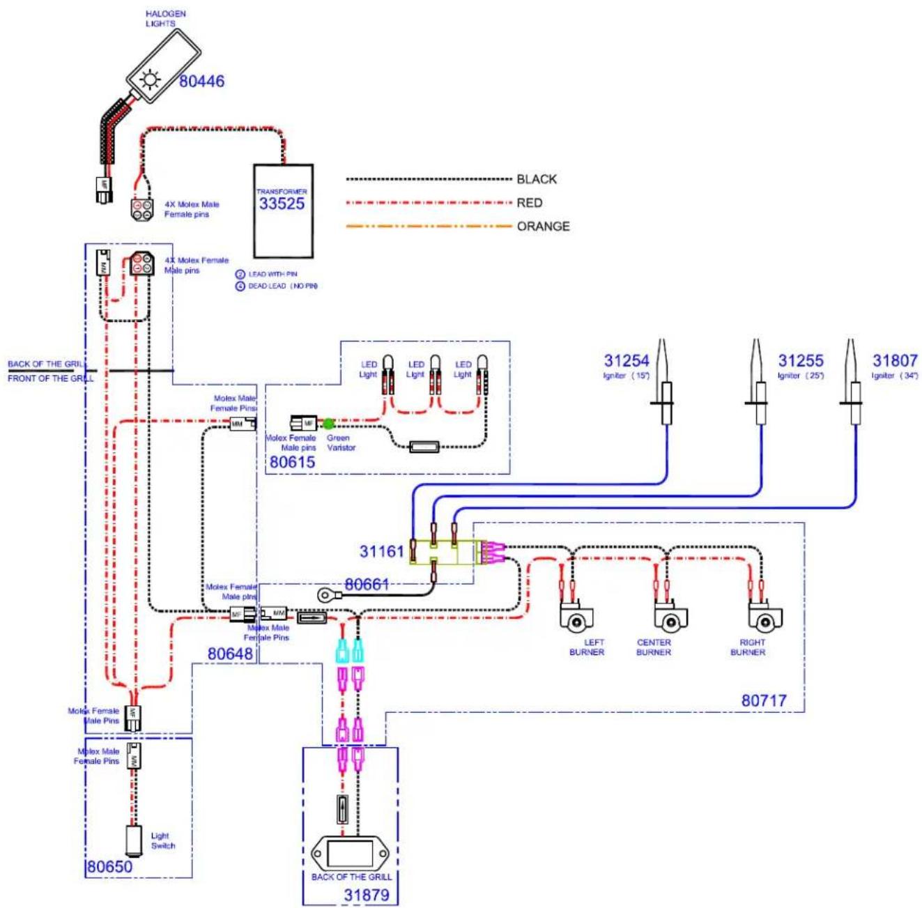
flowchart
graph TD
    A["HALOGEN LIGHTS"] --> B["80446"]
    B --> C["4X Motex Male Female pins"]
    C --> D["TRANSFORMER 33525"]
    D --> E["LEAD WITH PIN"]
    D --> F["DEAD LEAD (NO PIN)"]
    E --> G["Motex Female Male Pins"]
    F --> H["Green Varistor"]
    G --> I["Motex Male Female Pins"]
    H --> J["LED Light"]
    H --> K["LED Light"]
    H --> L["LED Light"]
    I --> M["Motex Female Male Pins"]
    J --> N["LED Light"]
    K --> O["LED Light"]
    L --> P["LED Light"]
    Q["BACK OF THE GRILL FRONT OF THE GRILL"] --> R["80615"]
    R --> S["80615"]
    S --> T["Motex Female Male Pins"]
    S --> U["Motex Male Female Pins"]
    T --> V["80648"]
    U --> W["80648"]
    V --> X["80650"]
    W --> Y["80650"]
    X --> Z["80650"]
    Y --> AA["80650"]
    Z --> AB["80650"]
    AA --> AC["80650"]
    AB --> AD["BACK OF THE GRILL 31879"]
    AD --> AE["80717"]
    AE --> AF["LEFT BURNER"]
    AE --> AG["CENTER BURNER"]
    AE --> AH["RIGHT BURNER"]
    AF --> AI["31254 Igniter (15)"]
    AG --> AJ["31255 Igniter (25)"]
    AH --> AK["31807 Igniter (34)"]
L600/L700 ROTISSERIE GRILL

flowchart
graph TD
    A["31173 Rotisserie Igniter"] --> B["80446 HALOGEN LIGHTS"]
    B --> C["4X Molex Male Female pins"]
    C --> D["TRANSFORMER 33525"]
    D --> E["LEAD WITH PIN"]
    D --> F["DEAD LEAD [NO PIN"]]
    E --> G["BACK OF THE GRILL FRONT OF THE GRILL"]
    F --> G
    G --> H["80436 Molex Male Female Pins"]
    H --> I["Molex Female Male Pins"]
    I --> J["80648 Molex Male Female Pins"]
    J --> K["80650 Molex Male Female Pins"]
    K --> L["Light Switch"]
    L --> M["BACK OF THE GRILL 31879"]
    D --> N["LED Light"]
    D --> O["LED Light"]
    D --> P["LED Light"]
    D --> Q["LED Light"]
    N --> R["ROTISSERIE BURNER"]
    O --> S["LEFT BURNER"]
    P --> T["CENTER BURNER"]
    Q --> U["RIGHT BURNER"]
    R --> V["31254 Igniter (15°)"]
    S --> W["31255 Igniter (25°)"]
    T --> X["31807 Igniter (34°)"]
    U --> Y["80475"]
SEDONA GRILL EXPLODED PARTS VIEW
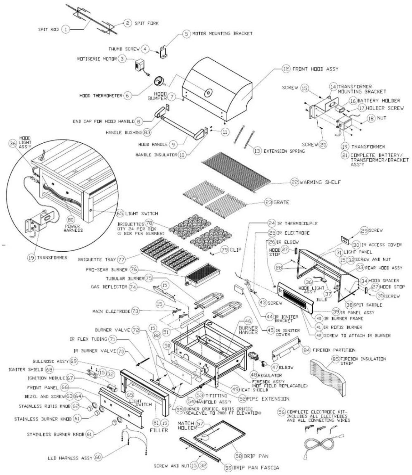
text_image
Technical diagram of a hood assembly with labeled components and parts, including motor mounting bracket, heater, and fixture parts.| ITEM | GRILL | PART NO. | DESCRIPTION |
| 1 | 24" | 34098 | SPIT ROD, L400 |
| 30" | 33783 | SPIT ROD, L500 | |
| 36" | 34074 | SPIT ROD, L600 | |
| 42" | 34604 | SPIT ROD, L700 | |
| 2 | ROTIS MODELS | 33813 | SPIT FORK |
| 3 | ROTIS MODELS | 33782 | ROTISERIE MOTOR 110 V |
| 4 | ROTIS MODELS | 33826 | THUMB SCREW FOR MOTOR BRACKET |
| 5 | ROTIS MODELS | 80659 | MOTOR MOUNTING BRACKET ASS'Y |
| 6 | ALL | 33558 | HOOD THERMOMETER |
| 7 | ALL | 32477 | HOOD BUMPER, .500 DIA |
| 8 | ALL | 11117 | END CAP FOR HOOD HANDLE |
| 9 | 24" | 34158 | HOOD HANDLE, L400 |
| 30" | 34200 | HOOD HANDLE, L500 | |
| 36" | 34075 | HOOD HANDLE, L600 | |
| 42" | 34605 | HOOD HANDLE, L700 | |
| 10 | ALL | 20016 | INSULATOR, HOOD HANDLE |
| 11 | ALL | 31601 | BOLT, HEX HEAD, 1/4-20 X 7/8", S/S |
| 12 | 24" | 80736 | FRONT HOOD ASSY, L400 |
| 30" | 80626 | FRONT HOOD ASSY, L500 | |
| 36" | 80697 | FRONT HOOD ASSY, L600 | |
| 42" | 80781 | FRONT HOOD ASSY, L700 | |
| 13 | ALL | 31780 | EXTENSION SPRING |
| 14 | ALL | 33827 | TRANSFORMER MOUNTING BRACKET |
| 15 | ALL | 14014 | SCREW #8-32 x 3/8 PH TRUSS HEAD S/S |
| 16 | ALL | 31879 | BATTERY HOLDER |
| 17 | ALL | 30751 | SCREW, #6-32 X 1/2 PH FLAT HEAT |
| 18 | ALL | 31238 | NUT, #8-32 S/S |
| 19 | ALL | 33525 | TRANSFORMER |
| 20 | ALL | 31013 | SCREW, #8 X 1/2 PH TRUSS HD TYPE 'A' |
| 21 | ALL | 80662 | COMPLETE TRANSFORMER/BATTERY BKT ASSY |
| 22 | 24" | 34097 | WARMING SHELF, L400 |
| 30" | 33778 | WARMING SHELF, L500 | |
| 36" | 34071 | WARMING SHELF, L600 | |
| 42" | 34601 | WARMING SHELF, L700 | |
| 23 | 24" | 34099 | GRATE- 10 1/2" X 17-3/4", L400 |
| 30',42" | 33779 | GRATE- 13 1/2" X 17-3/4", L500/L700 | |
| 36" | 34072 | GRATE- 16 1/2" X 17-3/4", L600 | |
| 42" | 34602 | GRATE- 12" X 17-3/4", L700 CENTER | |
| 24 | ROTIS MODELS | 20018 | IR THERMOCOUPLE |
| 25 | ROTIS MODELS | 31173 | IR ELECTRODE |
| 26 | ROTIS MODELS | 31795 | IR BRASS ELBOW, 7/16-20 MALE THREAD |
| 27 | ALL | 32468 | HOOD STOP |
| ALL | 32470 | BUMPER FOR HOOD STOP, .750 DIA | |
| 28 | ALL | 14013 | PIVOT SCREW, 1/4-20 X 1" HEX DRIVE |
| ALL | 14009 | PIVOT SCREW NUT, HEX, 1/4-20 S/S | |
| ALL | 14026 | PIVOT WASHER, SPLIT LOCK, 1/4 S/S | |
| 29 | ALL | 14012 | SCREW, 1/4-20 X 3/8 PH TRUSS HD, S/S |
| 30 | ALL | 30417 | IR ACCESS COVER |
| 31 | 24" | 34141 | LIGHT PANEL/REAR HOOD LINER, L400 |
| 30" | 33772 | LIGHT PANEL/REAR HOOD LINER, L500 | |
| 36" | 34065 | LIGHT PANEL/REAR HOOD LINER, L600 | |
| 42" | 34575 | LIGHT PANEL/REAR HOOD LINER, L700 | |
| 32 | ALL | 14024 | LOCK NUT, #8-32, S/S |
| 33 | 24" | 80737 | REAR HOOD ASSY, L400 |
| 30" | 80625 | REAR HOOD ASSY, L500 | |
| 36" | 80698 | REAR HOOD ASSY, L600 | |
| 42" | 80782 | REAR HOOD ASSY, L700 | |
| 34 | ALL | 33812 | HOOD SPACER, L500 |
| 35 | ALL | 32469 | SCREW/HOOD STOP-#8-32 X 1" PH TRUSS HD |
| 36 | ALL | 80446 | HOOD LIGHT ASSY, SINGLE W/10W BULB |
| 37 | ALL | 31979 | BULB, REPLACEMENT, 10W HALOGEN |
| ALL | 32322 | GLASS REPLACEMENT COVER W/ CLIP | |
| 38 | ALL | 10149 | SPIT SAIDLE |
| 39 | 24" | 80739 | IR PANEL ASSY, (INCLUDES BURNER), L400 |
| 30" | 80630 | IR PANEL ASSY, (INCLUDES BURNER), L500 | |
| 36" | 80700 | IR PANEL ASSY, (INCLUDES BURNER), L600 | |
| 42" | 80784 | IR PANEL ASSY, (INCLUDES BURNER), L700 | |
| 24" NON-JR | 80740 | REAR FINISHING PANEL, NON-ROTIS, L400 | |
| 30" NON-JR | 80631 | REAR FINISHING PANEL, NON-ROTIS, L500 | |
| 36" NON-JR | 80701 | REAR FINISHING PANEL, NON-ROTIS, L600 | |
| 42" NON-JR | 80788 | REAR FINISHING PANEL, NON-ROTIS, L700 | |
| 40 | 24",30" | 32991 | IR BURNER FRAME ONLY (16 IN.) |
| 36" | 32992 | IR BURNER FRAME ONLY (21 IN.) | |
| 42" | 32993 | IR BURNER FRAME ONLY (28 IN.) | |
| 41 | 24",30" | 32988 | IR ROTIS, BURNER ONLY (16 IN.) |
| 36" | 32989 | IR ROTIS, BURNER ONLY (21 IN.) | |
| 42" | 32990 | IR ROTIS, BURNER ONLY (28 IN.) | |
| 42 | ROTIS MODELS | 32644 | SCREW, #8-32 X 5/16 PH FLAT HD |
| 43 | ROTIS MODELS | 14018 | SCREW, #6-32 X 1/4 PH, PAN HD |
| 44 | ROTIS MODELS | 80753 | IR IGNITER BRACKET |
| 45 | 24",30" | 33135 | IR IGNITER COVER, 3-5/8" |
| 36",42" | 33136 | IR IGNITER COVER, 4-1/8" | |
| 46 | 24" | 80742 | BURNER HANGER, L400 |
| 30" | 80752 | BURNER HANGER, L500 | |
| 36" | 80751 | BURNER HANGER, L600 | |
| 42" | 80803 | BURNER HANGER, L700 | |
| 47 | ALL NG | 13010 | ELBOW, STREET, 1/2" 90 DEGREE-NG ONLY |
| ALL LP | 13054 | ELBOW, 3/8" FLARE TO 1/2" FIP-LP ONLY | |
| 48 | ALL NG | 30781 | REGULATOR 4/11 N/G ONLY |
| ALL LP | 13053 | REGULATOR W/30" HOSE DOUBLE STAGE-LP | |
| ITEM | GRILL | PART NO. | DESCRIPTION |
| 49 | 24" | 80748 | HEAT SHIELD, L400 |
| 30" | 80749 | HEAT SHIELD, L500 | |
| 36" | 80750 | HEAT SHIELD, L600 | |
| 42" | 80802 | HEAT SHIELD, L700 | |
| 50 | ALL | 14023 | NUT, COMBINATION (FOR HEAT SHIELD) |
| 51 | 30" | 33751 | BRIQUETTE HEAT DIVIDER |
| 52 | ALL | 34267 | PIPE EXTENSION 1/2 NPT X 5" |
| 53 | ALL | 13029 | 'T' FITTING, 1/2 FPT |
| ALL | 34268 | PIPE PLUG, 1/2 MPT, FOR 'T' FITTING | |
| 54 | 24"IR | 80729 | MANIFOLD ASS'Y W/VALVES, L400 W/ROTIS |
| 24"NON-IR | 80730 | MANIFOLD ASS'Y W/VALVES, L400 NON-ROTIS | |
| 30"IR | 80731 | MANIFOLD ASS'Y W/VALVES, L500 W/ROTIS | |
| 30"NON-IR | 80732 | MANIFOLD ASS'Y W/VALVES, L500 NON-ROTIS | |
| 36"IR | 80733 | MANIFOLD ASS'Y W/VALVES, L600 W/ROTIS | |
| 36"NON-IR | 80734 | MANIFOLD ASS'Y W/VALVES, L600 NON-ROTIS | |
| 42"IR | 80786 | MANIFOLD ASS'Y W/VALVES, L700 W/ROTIS | |
| 42"NON-IR | 80787 | MANIFOLD ASS'Y W/VALVES, L700 NON-ROTIS | |
| 55 | TUBE BURNER | 31880 | ORIFICE,BURNER, NG (#43 SHORT) |
| PROSEAR | 31880 | ORIFICE,BURNER, NG (#43 SHORT) | |
| ROTIS MODELS | 13016 | ORIFICE, IR ROTIS., NG (#50 SHORT) | |
| ALL LP | 13020 | ORIFICE,BURNER, LP (#54 SHORT) | |
| ROTIS MODELS | 13021 | ORIFICE, IR ROTIS., LP (#57 SHORT) | |
| 56 | 24"IR,30"IR | 90198 | COMPLETE ELECTRODE KIT, L400/L500 IR |
| 24",30"NON-IR | 90199 | COMPLETE ELECTRODE KIT, L400/L500 | |
| 36"/42"IR | 90207 | COMPLETE ELECTRODE KIT, L600,L700 IR | |
| 36"/42"NON-IR | 90208 | COMPLETE ELECTRODE KIT, L600,L700 NON-IR | |
| 57 | ALL | 31031 | ALTERNATE LIGHTING DEVICE, MATCH HOLDER |
| 58 | 24" | 33756 | DRIP PAN, L400/L500 |
| 30" | 33756 | DRIP PAN, L400/L500 | |
| 36" | 34057 | DRIP PAN, L600 | |
| 42" | 34567 | DRIP PAN, L700 | |
| 59 | 24" | 34144 | DRIP PAN FASCIA, L400 |
| 30" | 33757 | DRIP PAN FASCIA, L500 | |
| 36" | 34058 | DRIP PAN FASCIA, L600 | |
| 42" | 34568 | DRIP PAN FASCIA, L700 | |
| 60 | 24"IR,30"IR | 80435 | LED HARNESS ASSY, L400/L500 W/IR |
| 24",30"NON-IR | 80614 | LED HARNESS ASSY, L400/L500 NON-IR | |
| 36"/42"IR | 80436 | LED HARNESS ASSY, L600/L700 W/IR | |
| 36",42"NON-IR | 80615 | LED HARNESS ASSY, L600/L700 NON-IR | |
| ALL | 32554 | LED HOLDER | |
| 61 | ALL | 90137 | KNOB, BURNER, STAINLESS |
| 62 | ROTIS MODELS | 90136 | KNOB, ROTIS, STAINLESS |
| 63 | ALL | 10001 | BEZEL |
| 64 | ALL | 31929 | BEZEL SCREW, #6-32 X 1/8 PH PAN |
| 65 | ALL | 80650 | LIGHT SWITCH + HARNESS ASSY |
| 66 | 24"IR | 34137 | FRONT PANEL, L400 W/ ROTIS |
| 24"NON IR | 34159 | FRONT PANEL, L400 NON-ROTIS | |
| 30"IR | 33761 | FRONT PANEL, L500 W/ ROTIS | |
| 30"NON IR | 33775 | FRONT PANEL, L500 NON-ROTIS | |
| 36"IR | 34060 | FRONT PANEL, L600 W/ ROTIS | |
| 36"NON IR | 34080 | FRONT PANEL, L600 NON-ROTIS | |
| 42"IR | 34570 | FRONT PANEL, L700 W/ ROTIS | |
| 42"NON IR | 34612 | FRONT PANEL, L700 NON-ROTIS | |
| 67 | ALL IR,36",42" | 31161 | IGNITION MODULE- 4 SPARK |
| 24",30"NON-IR | 31162 | IGNITION MODULE- 2 SPARK | |
| 68 | ALL | 31398 | IGNITER SHIELD |
| 69 | 24" | 80738 | BULLNOSE ASS'Y, L400 |
| 30" | 80627 | BULLNOSE ASS'Y, L500 | |
| 36" | 80699 | BULLNOSE ASS'Y, L600 | |
| 42" | 80783 | BULLNOSE ASS'Y, L700 | |
| 70 | ROTIS MODELS | 31772 | IR BURNER VALVE W/ MICROSWITCH |
| 71 | ROTIS MODELS | 31794 | FLEX HOSE, 9 MM X 38" W/ 7/16 FITTINGS |
| 72 | ALL | 33339 | MAIN BURNER VALVE W/ MICROSWITCH |
| ALL | 32845 | MICROSWITCH REPLACEMENT FOR VALVE | |
| 73 | ALL | 31254 | ELECTRODE W/ 15" WIRE (SEE ALSO #56) |
| ALL | 31255 | ELECTRODE W/ 25" WIRE (SEE ALSO #56) | |
| 36",42" | 31807 | ELECTRODE W/ 34" WIRE (SEE ALSO #56) | |
| 74 | 24" | 34160 | GAS DEFLECTOR, L400 |
| 30" | 31673 | GAS DEFLECTOR, L500 | |
| 36" | 34079 | GAS DEFLECTOR, L600 | |
| 42" | 34578 | GAS DEFLECTOR, L700 | |
| 75 | ALL | 33750 | TUBULAR BURNER |
| 76 | ALL | 33943 | PROSEAR BURNER |
| 77 | 24",36",42" | 80743 | BRIQUETTE TRAY W/BRIGUETTES AND CLIPS |
| 30",42" | 80744 | BRIQUETTE TRAY W/BRIGUETTES AND CLIPS | |
| 78 | ALL | 90183 | BRIQUETTES, 24 PER BOX |
| 79 | ALL | 34246 | BRIQUETTE HOLT-DOWN CLIP |
| 80 | ALL | 80648 | MAIN POWER HARNESS, L400, L500, L600 |
| 81 | 24" | 34163 | BULLNOSE FILLER PLATE, L400 |
| 30" | 34164 | BULLNOSE FILLER PLATE, L500 | |
| 36" | 34165 | BULLNOSE FILLER PLATE, L600 | |
| 42" | 33540 | BULLNOSE FILLER PLATE, L700 | |
| 82 | 24" | 34177 | INSULATION COVER PLATE, L400 |
| 30" | 34178 | INSULATION COVER PLATE, L500 | |
| 36" | 34179 | INSULATION COVER PLATE, L600 | |
| 42" | 34582 | INSULATION COVER PLATE, L700 | |
| 83 | ALL | 31738 | HANDLE BUSHING |
| 84 | 30",36" | 33894 | FIREBOX PARTITION |
| 85 | 24" | 34251 | FIREBOX INSULATION STRIP-6"x24"x1-1/2" |
| 30" | 34252 | FIREBOX INSULATION STRIP-9"x30"x1-1/2" | |
| 36" | 34253 | FIREBOX INSULATION STRIP-6"x36"x1-1/2" | |
| 42" | 34658 | FIREBOX INSULATION STRIP-6"x42"x1-1/2" |
| MODEL-SPECIFIC BTU OUTPUTS | ||||
| MODEL TUBE BUR | NER ROTISSERIE PROSE | EARTM TOTAL INPUT | ||
| L400PS 1 @ 23,000 | Btu/Hr N/A 1 @ 23,000 Btu/Hr 46,000 Btu/Hr | |||
| L400PSR 1 @ 23,000 | Btu/Hr 1 @ 12,500 Btu/Hr 1 @ 23,000 Btu/Hr 58,500 | Btu/Hr | ||
| L500PS 1 @ 23,000 | Btu/Hr N/A 1 @ 23,000 Btu/Hr 46,000 Btu/Hr | |||
| L500PSR 1 @ 23,000 | Btu/Hr 1 @ 12,500 Btu/Hr 1 @ 23,000 Btu/Hr 58,500 | Btu/Hr | ||
| L600PS 2 @ 23,000 | Btu/Hr N/A 1 @ 23,000 Btu/Hr 69,000 Btu/Hr | |||
| L600PSR 2 @ 23,000 | Btu/Hr 1 @ 14,000 Btu/Hr 1 @ 23,000 Btu/Hr 83,000 | Btu/Hr | ||
| L700PS 2 @ 23,000 | Btu/Hr N/A 1 @ 23,000 Btu/Hr 69,000 Btu/Hr | |||
| L700PSR 2 @ 23,000 | Btu/Hr 1 @ 16,000 Btu/Hr 1 @ 23,000 Btu/Hr 85,000 | Btu/Hr | ||
| MAXIMUM RUNS FOR ALL APPLIANCES ON SUPPLY LINE | |
| Run Length 3/4" Pipe (in feet) | Max BTU for all Appliances on line |
| 10 360,000 | |
| 20 245,000 | |
| 30 198,000 | |
| 40 169,000 | |
| 50 150,000 | |
| 60 135.000 | |
| 70 123,000 | |
| 80 115,000 | |
INDEX
A
Air Shutter Adjustment 30
B
Before Each Use 7,8
Before You Start 22
BTU Outputs, Model Specific .. 38
Burner Adjustment, Low...... 30
Burner Adjustment, Main ..... 30
Burner Appearance 30
Burner Placement 15
C
Checklist Before Each Use..... 7, 8
Cleaning the Burner 15
Cleaning Your Grill.... 14
Clearance to Combustibles..... 23
Coastal Use....14
Contacting Lynx Customer Care 18
Cut-out Dim., Built-in Grill...... 24
D
Damage 22
Concealed 22
Visible 22
Direct Heat Cooking 10
Drip Tray 14
E
Electrical Connections ...... 29
Connection to AC 29
Battery Installation 29
Exploded Parts View 36
F
Final Checks 30
Flame, Correct Size 30
G
Gas Connections 27
Gas Line Purging 28
Gas Requirements 26
Gas Supply Line Runs 38
Gas Type Conversion......28
Grilling in Windy Conditions ..... 6
|
Important Safety Precautions ..... 5
Indirect Heating 10
L
Leak Test Procedure 30
Lighting, Manual 9
Lighting, Rotisserie Burner ...... 9
Lighting Your Grill 8
Low Heat Burner Adjustment .. 30
LP Cylinder Requirements ..... 28
LP Gas 27
M
Manual Lighting.... 9
Match Lighting 9
Maximum Runs for all appliances on supply line...... 38
P
Parts List 37
Parts View, Exploded 36
Pool Side Use 14
Pre-Heating ProSear™ Burner.. 11
Pre-Heating the Grill 10
Purging the Gas Line 28
R
Regulator Conversion...... 27
S
Schematics, L400/L500 Grill ..... 32
Schematics, L600 Grill 34
Service, contacting Lynx ...... 18
T
Technical Support 18
Troubleshooting 16
U
Unpacking and Assembly...... 25
Using Your Grill 7
W
Warranty 19
Windy Conditions, Grilling in ..... 6
Lynx Professional Grills
7300 Flores Street
Downey, CA 90242
Lynx Customer Care: 888.289.5969
Fax: 562-299-6978
www.lynxgrills.com
