95-1003 - Kit voiture Metra - Free user manual and instructions
Find the device manual for free 95-1003 Metra in PDF.

User questions about 95-1003 Metra
0 question about this device. Answer the ones you know or ask your own.
Ask a new question about this device
Download the instructions for your Kit voiture in PDF format for free! Find your manual 95-1003 - Metra and take your electronic device back in hand. On this page are published all the documents necessary for the use of your device. 95-1003 by Metra.
USER MANUAL 95-1003 Metra
INSTALLATION INSTRUCTIONS FOR PART 95-1003
APPLICATIONS
KIA
Rio 2001
Sephia 1995-2001
Spèctra 2000-2001
Sportage 1998-2003
95-1003
KIT FEATURES
• DDIN Head Unit Provision
• ISO Stacked Head Unit Provision
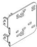
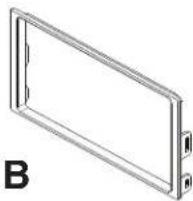
KIT COMPONENTS

natural_image
Close-up of a black electronic device with a display screen and control buttons (no visible text or symbols)A) DDIN Brackets • B) DDIN Trim Plate #1 • B) DDIN Trim Plate #2
A

natural_image
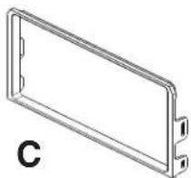
Technical line drawing of a rectangular frame with mounting holes and a label 'C' (no text or symbols on the diagram itself)WIRING AND ANTENNA CONNECTIONS
(Sold Separately)
• 70-1003 - KIA Harness 1995-02
- Antenna Adapter N/R
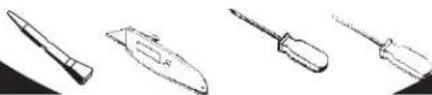
TOOLS REQUIRED:
Panel Removal Tool • Cutting Tool • Phillips Screwdriver
• Small Flat Blade Screwdriver
natural_image
Line drawings of four different types of writing tools or instruments (no text or symbols present)TABLE OF CONTENTS
Dash Disassembly
- Kia Rio 2001 .... 1
- Sephia 1995-1997 .... 2
- Sephia 1998-2001 .... 3
- Spectra 2000-2001....3
- Sportage 1998-2000 .... 4
- Sportage 2001-2003 .... 5
Kit Assembly
- Kit Assembly Preparation ....6
- DDIN / Stacked ISO DIN Radio Provision 7

text_image
INSTALLER INSTITUTEKNOWLEDGE IS POWER
Enhance your installation and fabrication skills by enrolling in the most recognized and respected mobile electronics school in our industry. Log onto www.installerinstitute.com or call 800-354-6782 for more information and take steps toward a better tomorrow.

text_image
M CpMetra recommends MECP certified technicians
\*Note:
Refer also to the instructions included with the aftermarket radio.
RIO 2001
*Note: Refer also to the instructions included with the aftermarket radio.
1 Disconnect the negative battery-terminal to prevent an accidental short circuit.
2 Remove ashtray and (1) Phillips head screw inside ashtray cavity. (Figure A)
3 Remove knob from climate control slide lever. (Figure B)
4 Unsnap and remove radio/climate control trim panel. (Figure C)
5 Remove (4) Phillips head screws securing the radio. Unplug and remove the radio.
Continue to kit preparation.

text_image
A
text_image
B OFF AC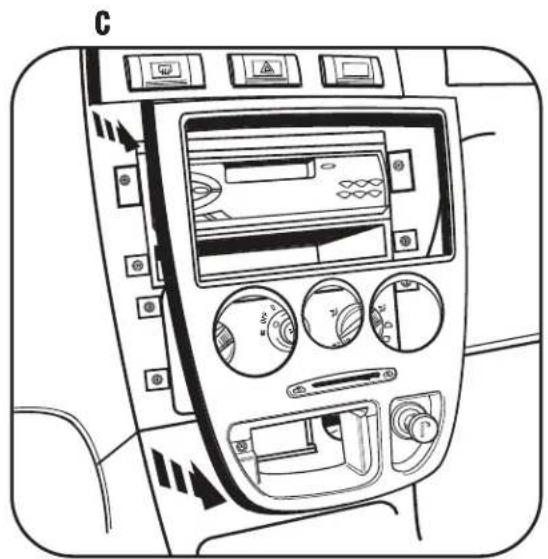
natural_image
Interior view of a car dashboard with air filters and control buttons (no text or symbols visible)SEPHIA 1995-1997
*Note: Refer also to the instructions included with the aftermarket radio.
1 Disconnect the negative battery terminal to prevent an accidental short circuit.
2 Remove plastic screw cover to the left of the coin tray and remove the Phillips head screw from behind cover.
3 Remove switch blank to the far right of the switch panel and remove the Phillips head screw from behind switch blank.
4 Unclip and remove dash trim panel.
5 Remove (4) Phillips head screws securing the radio. Unplug and remove the radio.
Continue to kit preparation.

natural_image
Technical line drawing of two mechanical components with internal compartments and mounting holes (no text or symbols)SEPHIA 1998-2001
SPECTRA 2000-2001
*Note: Refer also to the instructions included with the aftermarket radio.
1 Disconnect the negative battery terminal to prevent an accidental short circuit.
2 Remove (1) Phillips head screw from above instrument cluster.
3 Unclip and remove dash trim panel.
4 Remove (4) Phillips head screws securing the radio. Unplug and remove the radio.
Continue to kit preparation.
natural_image
Technical line drawing of a mechanical housing or enclosure component (no text or symbols)SPORTAGE 1998-2000
*Note: Refer also to the instructions included with the aftermarket radio.
1 Disconnect the negative battery terminal to prevent an accidental short circuit.
2 Unclip and remove dash trim panel.
3 Remove (4) Phillips head screws securing the radio. Unplug and remove the radio.
Continue to kit preparation.

natural_image
Technical line drawing of a mechanical housing with internal components (no text or symbols)SPORTAGE 2001-2003
*Note: Refer also to the instructions included with the aftermarket radio.
1 Disconnect the negative battery terminal to prevent an accidental short circuit.
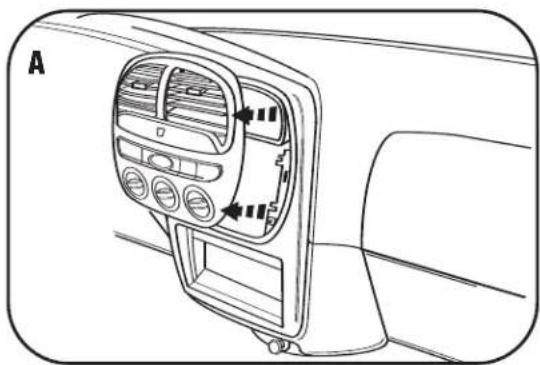
2 Unclip and remove climate control/vent trim panel. (Figure A)
3 Remove screw covers from trim panel below steering column and remove screws from behind covers. Lower the trim panel (it is not necessary to remove the panel). (Figure B)
4 Remove (3) Phillips head screws from bottom of steering column housing and remove both upper and lower sections of housing.
5 Remove (1) Phillips head screw from outside left edge of dash and (2) Phillips head screws from near hood release. (Figure C)
6 Loosen nut behind hood release and remove lower left side dash trim. (Figure C)
7 Remove (4) Phillips head screws from instrument trim panel and remove panel. (Figure D)
8 Remove (4) Phillips head screws securing the radio. Unplug and remove the radio.
Continue to kit assembly.
natural_image
Interior view of a car dashboard with air vent and control panel (no text or symbols)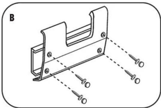
natural_image
Technical line drawing of a mechanical bracket with mounting holes and dashed alignment lines (no text or symbols)
natural_image
Technical line drawing of a mechanical component with a screw and mounting bracket (no text or symbols)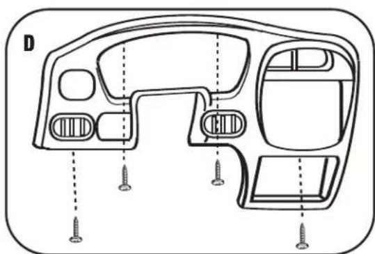
natural_image
Technical line drawing of a car dashboard with screw fasteners and mounting holes (no text or symbols)KIT ASSEMBLY PREPARATION
*Note: Refer also to the instructions included with the aftermarket radio.
RIO 2001
SEPHIA 1995-1997
Use the trim with notched corners at the top and the first set of tabs on the brackets. (Figure A)
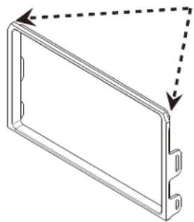
SEPHIA 1998-2001
SPECTRA 2000-2001
Use the trim without the notched corners and the second set of mounting tabs. (Figure B)
A
natural_image
Pure technical line drawing of a rectangular component with dashed arrows indicating direction (no text or symbols)B
natural_image
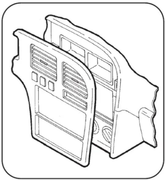
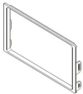
Isometric line drawing of a rectangular frame with two side connectors (no text or symbols)SPORTAGE 1998-2003 DDIN BRACKETS
Use the trim without the notched corners and the third set of mounting tabs. (Figure C)
Use the following sets of mounting tabs for each model respectively. The fourth set of tabs will not be used in this kit.
C

natural_image
Isometric line drawing of a rectangular frame with two small protrusions on both sides (no text or symbols)
text_image
D 1st Set 2nd Set 3rd Set 4th Set (Not Used in this kit)Continue to kit assembly.
DOUBLE DIN / STACKED ISO DIN HEAD UNIT PROVISION
*Note: Refer also to the instructions included with the aftermarket radio.
1 Locate the factory wiring harness in the dash. Metra recommends using the proper mating adapter from Metra or AXXESS. Re-connect the negative battery terminal and test the unit for proper operation.
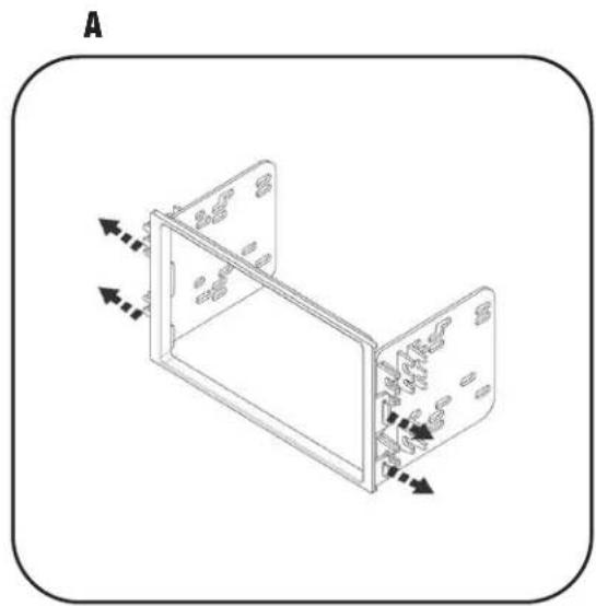
2 Clip the brackets into the sides of the DDIN trim plate. (Figure A)
3 Slide the Double DIN head unit or stacked ISO head units into the bracket/radio housing assembly and secure to the assembly using the screws supplied with the radio. (Figure B)
4 Reassemble dash in reverse order of disassembly.
natural_image
Isometric line drawing of a two-panel electronic device with directional arrows indicating movement (no text or symbols)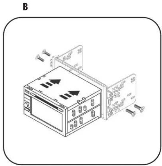
natural_image
Diagram of an electronic device with two panels and screw connectors, no text or symbols present95-1003 INSTRUCTIONS