95-3009 - Kit voiture Metra - Free user manual and instructions
Find the device manual for free 95-3009 Metra in PDF.

User questions about 95-3009 Metra
0 question about this device. Answer the ones you know or ask your own.
Ask a new question about this device
Download the instructions for your Kit voiture in PDF format for free! Find your manual 95-3009 - Metra and take your electronic device back in hand. On this page are published all the documents necessary for the use of your device. 95-3009 by Metra.
USER MANUAL 95-3009 Metra
natural_image
Interior view of a car dashboard and infotainment system (no visible text or symbols)Chevrolet Camaro 1993-1996
KIT FEATURES
- ISO DDIN radio provision
- Replacement trim panel is textured to match the factory finish
KIT COMPONENTS
• A) Radio trim panel • B) Radio brackets • C) (1) #10 x 1/2" Phillips screw
A

natural_image
Line drawing of a mechanical component or bracket (no text or symbols)B

natural_image
Line drawing of two abstract mechanical components with no text or symbolsC

TABLE OF CONTENTS
Dash Disassembly 2
Kit Preparation 2
Kit Assembly 3
WIRING & ANTENNA CONNECTIONS(sold separately)
Wiring Harness: 70-1858
Antenna Adapter: 40-GM10
TOOLS REQUIRED
- Panel removal tool • Phillips screwdriver
- 9/32", 10mm Socket wrench - Cutting tool
CAUTION! All accessories, switches, climate controls panels, and especially air bag indicator lights must be connected before cycling the ignition. Also, do not remove the factory radio with the key in the on position, or while the vehicle is running.
DASH DISASSEMBLY KIT PREPA
- Remove (2) Phillips screws from the top of the driver's side knee bolster.
- Remove (2) 9/32" screws from the bottom of the knee bolster.
- Open the glove box, remove (3) 9/32" screws exposed on the right edge of the radio trim bezel and remove the bezel. (Figure A)
- Remove (2) 9/32" screws securing the left side of the factory radio and (1) 10mm nut securing the right.
- Slide the radio from the dash and disconnect the wiring.

natural_image
Technical line drawing of a mechanical housing assembly (no text or symbols)(Figure A)
Continue to Kit Preparation
ATION
- Using a cutting tool, remove the section of subdash indicated. (Figure A)
Continue to Kit Assembly

natural_image
Technical diagram of a vehicle interior showing dashboard and airway components with no visible text or symbols(Figure A)
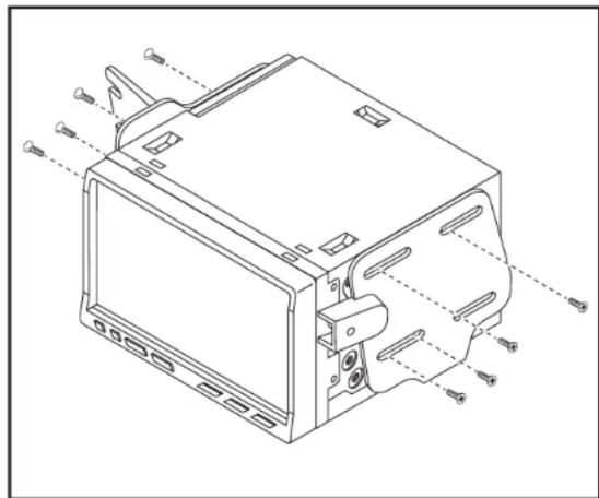
KIT ASSEMBLY
ISO DDIN radio provision
- Attach the radio brackets to the radio using the screws supplied with the radio. (Figure A)
- Locate the factory wiring harness and connector in the dash and complete all necessary connections to the radio. Metra recommends using the proper mating adapter from Metra. Test the radio for proper operation.
- Secure the completed assembly into the dash. Use the factory screws for the drivers side radio bracket and (1) #10 x 1/2" Phillips screw provided into the passenger side of the radio bracket.
- Reassemble the dash in reverse order of disassembly, using the radio trim panel instead of the factory panel.
natural_image
Technical line drawing of a computer monitor case with labeled ports and connectors (no text or symbols present)(Figure A)
IMPORTANT
If you are having difficulties with the installation of this product, please call our Tech Support line at 1-800-253-TECH. Before doing so, look over the instructions a second time, and make sure the installation was performed exactly as the instructions are stated. Please have the vehicle apart and ready to perform troubleshooting steps before calling.

KNOWLEDGE IS POWER
Enhance your installation and fabrication skills by enrolling in the most recognized and respected mobile electronics school in our industry.
Log onto www.installenstitute.com or call 800-354-6782 for more information and take steps toward a better tomorrow.

Metra recommends MECP certified technicians