99-7951 - Kit voiture Metra - Free user manual and instructions
Find the device manual for free 99-7951 Metra in PDF.

User questions about 99-7951 Metra
0 question about this device. Answer the ones you know or ask your own.
Ask a new question about this device
Download the instructions for your Kit voiture in PDF format for free! Find your manual 99-7951 - Metra and take your electronic device back in hand. On this page are published all the documents necessary for the use of your device. 99-7951 by Metra.
USER MANUAL 99-7951 Metra
INSTALLATION INSTRUCTIONS FOR PART 99-7951
APPLICATIONS
CHEVROLET
Aveo 2004-2006
Aveo Hatchback-2007-2008
SUZUKI
Forenza 2004-2008
Reno 2005-2008
Verona 2004-2007
PONTIAC
G3 Hatchback-2007
99-7951
KIT FEATURES
• DIN Head Unit Provision with pocket
• ISO DIN Head Unit Provision with pocket
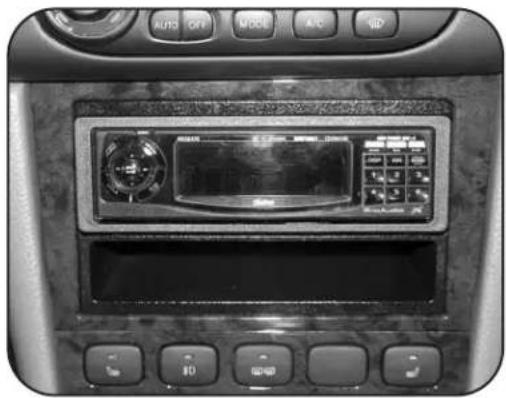
natural_image
Interior view of a car dashboard with control buttons and a central touchscreen display (no readable text or symbols)KIT COMPONENTS
A) Radio Housing
B) ISO Brackets
C) Trim Plate

natural_image
Technical line drawing of a mechanical assembly with labeled components A and C (no text or symbols beyond labels)C

natural_image
Technical line drawing of a mechanical bracket assembly with two views (no text or symbols)WIRING AND ANTENNA CONNECTIONS (Sold Separately)
Harness:
• 70-8405 - GM/Suzuki/Daewoo harness 1999-up
Antenna Adapter:
- Not required
TOOLS REQUIRED:
Phillips Screwdriver • Flat Blade Screwdriver Or Panel Removal Tool


1-800-221-0932

www.metraonline.com
© COPYRIGHT 2004-2009 METRA ELECTRONICS CORPORATION
TABLE OF CONTENTS
- Dash Disassembly
- Suzuki Verona 2004 - 2007 ---- 1
- Chevrolet Aveo 2004 - 2006 2
- Chevrolet Aveo Hatchback - 2007-2008---- 2
-
Pontiac G3 Hatchback - 2007 ---- 2
-
Suzuki Forenza 2004-2008 ---- 3
- Suzuki Reno 2005-2008 ----3
- Kit Assembly
Chevrolet Aveo/Aveo Hatchback/Pontiac Hatchback/Suzuki Verona :
- DIN Head Unit Provision with Pocket 4
- ISO Head Unit Provision with Pocket 5
Suzuki Forenza /Suzuki Reno :
- DIN Head Unit Provision with Pocket 6
- ISO Head Unit Provision with Pocket 7
• Final Assembly 8

text_image
INSTALLER INSTITUTEKNOWLEDGE IS POWER
Enhance your installation and fabrication skills by enrolling in the most recognized and respected mobile electronics school in our industry. Log onto www.installerinstitute.com or call 800-354-6782 for more information and take steps toward a better tomorrow.
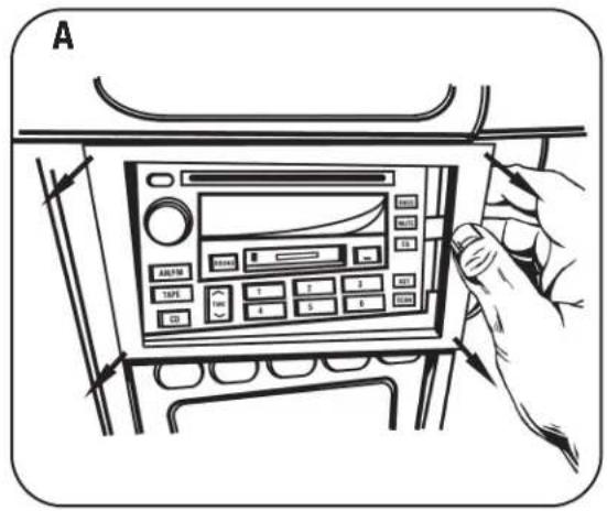
SUZUKI VERONA 2004 - 2007
1 Disconnect the negative battery terminal to prevent an accidental short circuit.
2 Unclip and remove the trim plate panel surrounding the radio. (Figure A)
3 Remove (4) Phillips screws holding radio to remove. (Figure B)
text_image
A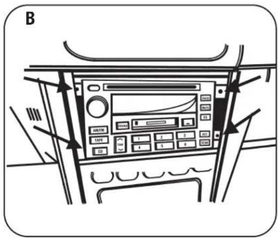
text_image
B AUSTIN TAPE ED 1 2 3 4 5 6 7 8 9 10 11 12 13 14 15 16 17 18 19 20 21 22 23 24 25 26 27 28 29 30 31 32 33 34 35 36 37 38 39 40 41 42 43 44 45 46 47 48 49 50 51 52 53 54 55 56 57 58 59 60CHEVROLET AVEO 2004 - 2006 CHEVROLET AVEO HATCHBACK - 2007-2008 PONTIAC G3 HATCHBACK - 2007
1 Disconnect the negative battery terminal to prevent an accidental short circuit.
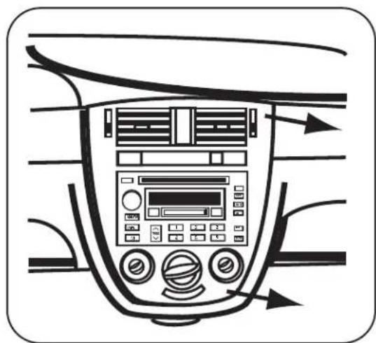
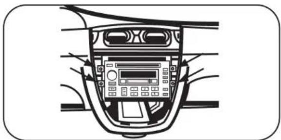
2 Unclip and remove the trim panels from both sides of radio/climate controls. (Figure A)
3 Remove (4) Phillips screws from radio to remove. (Figure B)
text_image
A A/C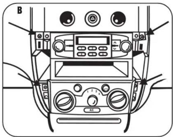
text_image
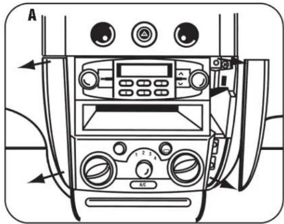
B A/CSUZUKI FORENZA 2004-2008 SUZUKI RENO 2005-2008
A
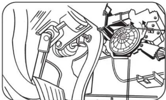
1 Disconnect air selector cable on drivers side of center console behind dash above accelerator pedal. (Figure A & B)
2 Open glove box and remove (5) Phillips screws ((3) on top and (2) on bottom) then remove entire glove.
3 Disconnect temperature selector cable on passenger side of center console behind glove box. (Figure C)
4 Unsnap and remove entire panel surrounding radio. Note: The clips holding radio panel to dash are very strong. (Figure D)
5 Remove (4) 10 MM bolts securing radio to remove. (Figure E)
D
natural_image
Interior view of a car dashboard with air filters and control panel (no text or symbols)
text_image
Underside of dash on drivers side. Front of vehicle.B
natural_image
Technical line drawing of a mechanical assembly with no visible text or symbolsC

text_image
Inside of Glove BoxE
natural_image
Diagram of a car dashboard with control panel and navigation arrows (no text or symbols)CHEVROLET AVEO 2004 - 2006 CHEVROLET AVEO HATCHBACK - 2007-2008 PONTIAC G3 HATCHBACK - 2007 SUZUKI VERONA 2004-2007 DIN HEAD UNIT PROVISION
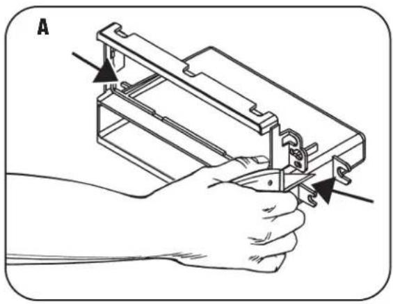
1 Cut and remove front lower mounting tabs from radio housing. (Figure A)
2 Slide the DIN cage into the Radio Housing and secure by bending the metal locking tabs down. (Figure B)
3 Slide the aftermarket head unit into the cage and secure. (Figure C)

natural_image
Line drawing of a hand holding a mechanical device with arrows indicating force or movement (no text or symbols present)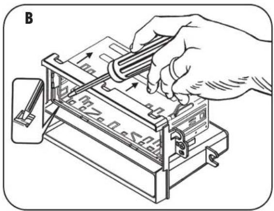
natural_image
Illustration of a hand using a tool to adjust or install a mechanical component (no text or symbols visible)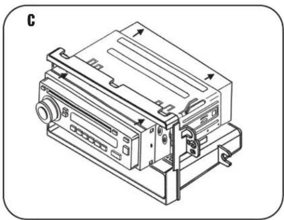
natural_image
Technical line drawing of a mechanical device with ports and mounting base (no text or symbols)CHEVROLET AVEO 2004 - 2006 CHEVROLET AVEO HATCHBACK - 2007-2008 PONTIAC G3 HATCHBACK - 2007 SUZUKI VERONA 2004-2007
ISO DIN HEAD UNIT PROVISION
1 Cut and remove front lower mounting tabs from radio housing. (Figure A)
2 Mount the ISO Brackets to the head unit with the screws supplied with the unit. (Figure B)
3 Slide the head unit into the radio opening until the side clips engage. (Figure C)
4 Snap the Trim plate into the Radio Housing. (Figure C)
natural_image
Line drawing of a hand holding a mechanical device with arrows indicating assembly or adjustment (no text or symbols present)
natural_image
Line drawing of a hand using a screwdriver to adjust or install a device into a rectangular box (no text or symbols)
text_image
C Right Side ClipSUZUKI FORENZA 2004-2008 SUZUKI RENO 2005-2008
DIN HEAD UNIT PROVISION WITH POCKET
1 Cut and remove rear lower mounting tabs from radio housing. (Figure A)
2 Slide the DIN cage into the Radio Housing and secure by bending the metal locking tabs down. (Figure B)
3 Slide the aftermarket head unit into the cage and secure. (Figure C)

natural_image
Line drawing of a hand using a tool to cut or adjust a mechanical component (no text or symbols present)
text_image
B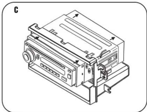
natural_image
Technical line drawing of a mechanical device with ports and mounting bracket (no text or symbols)SUZUKI FORENZA 2004-2008 SUZUKI RENO 2005-2008
ISO DIN HEAD UNIT PROVISION
1 Cut and remove rear lower mounting tabs from radio housing. (Figure A)
2 Mount the ISO Brackets to the head unit with the screws supplied with the unit. (Figure B)
3 Slide the head unit into the radio opening until the side clips engage. (Figure C)
4 Snap the Trim plate into the Radio Housing. (Figure C)

natural_image
Line drawing of a hand using a tool to adjust or install a mechanical component (no text or symbols present)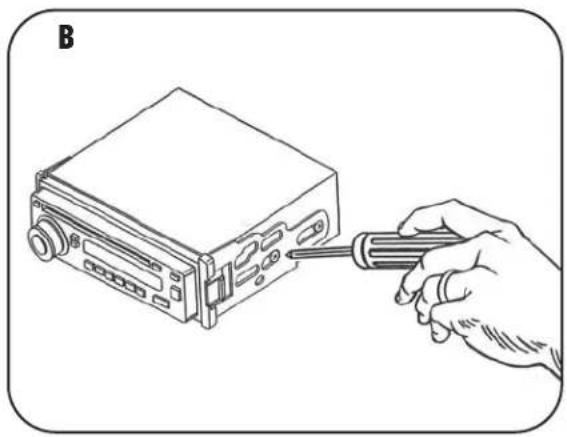
natural_image
Line drawing of a hand using a screwdriver to adjust or install a device from a computer case (no text or symbols present)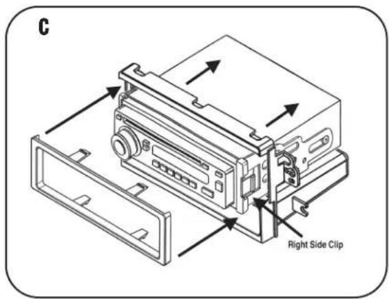
text_image
C Right Side ClipFINAL ASSEMBLY

text_image
A B C D1 Locate the factory wiring harness in the dash. Metra recommends using the proper mating adapter and making connections as shown. (Isolate and individually tape off the ends of any unused wires to prevent electrical short circuit.)
2 Re-connect the negative battery terminal and test the unit for proper operation.
3 Snap radio housing assembly into factory radio opening.
FINAL WIRING CONNECTIONS
Make wiring connections using the EIA color code chart shown below and the instructions included with the head unit. Metra recommends making connections as shown below; Strip, Splice, Solder, Tape. Isolate and individually tape off ends of any unused wires to prevent electrical short circuit.
METRA / EIA WIRING CODE
12V Ignition / Acc ... Red
12V Batt / Memory .. Yellow
Ground .... Black*
Power Antenna ..... Blue
Amp Turn-On ..... Blue / White
Amp Ground ..... Black / White
Illumination.....Orange
Dimmer ..... Orange / White
Right Front (+) ..... Gray
Right Front (-) ..... Gray/ Black
Left Front (+) ..... White
Left Front (-) ..... White / Black
Right Rear (+).....Violet
Right Rear (-) ..... Violet / Black
Left Rear (+).... Green
Left Rear (-) ..... Green / Black
*NOTE: When a Black wire is not present, ground radio to vehicle chassis. All colors may not be present on all leads due to manufacturer's specifications.