
PD-2604UE - Point of Sale Terminal Posiflex - Free user manual and instructions
Find the device manual for free PD-2604UE Posiflex in PDF.

| Product Information | |
| Product Type | Customer Pole Display |
| Model | PD-2604UE |
| Brand | Posiflex |
| Display | |
| Display Type | VFD (Vacuum Fluorescent Display) |
| Number of Lines | 2 |
| Characters per Line | 20 |
| Character Size (H x W) | 9.03 mm x 5.25 mm |
| Display Color | Yellow-green characters with dark blue background |
| Interface & Compatibility | |
| Interface | USB (USB-HID Class, USB-Vendor Class, Virtual COM Port) |
| Emulation Modes | UTC, Aedex, Noritake, Epson, Futaba, ADM (selectable via DIP switch) |
| Compatibility | Designed for rear mount on Posiflex KS series (10\"/12\"/15\" models) |
| Physical Specifications | |
| Display Head Dimensions (H x W x D) | 58 mm x 197 mm x 39.5 mm |
| Case Color | Black |
| Weight | Approximately 0.5 kg (estimated) |
| Electrical | |
| Power Supply | Powered via USB (5V DC, 800 mA) |
| Environmental | |
| Operating Temperature | 0° to +40°C |
| Storage Temperature | -10° to +60°C |
| Operating Humidity | 20% to 85% non-condensing |
| Storage Humidity | 5% to 90% non-condensing |
| Safety & Maintenance | |
| Safety Warning | Not suitable for locations where children are likely to be present. Warranty void if opened by unauthorized personnel. |
| Cleaning Instructions | Clean with a soft dry cloth. Do not use liquid cleaners. |
| Maintenance | No user-serviceable parts. Refer service to qualified technician. |
| Included Accessories | |
| Mounting Kit | 2 shoulder screws and rear bracket for KS series attachment |
Frequently Asked Questions - PD-2604UE Posiflex
User questions about PD-2604UE Posiflex
0 question about this device. Answer the ones you know or ask your own.
Ask a new question about this device
Download the instructions for your Point of Sale Terminal in PDF format for free! Find your manual PD-2604UE - Posiflex and take your electronic device back in hand. On this page are published all the documents necessary for the use of your device. PD-2604UE by Posiflex.
USER MANUAL PD-2604UE Posiflex
PD – 260XUE/2800UE Series User's Manual
FCC NOTES
Rev. C0
This equipment has been tested and found to comply with the limits for a Class A digital device, pursuant to part 15 of the FCC Rules. These limits are designed to provide reasonable protection against harmful interference when the equipment is operated in a commercial environment. This equipment generates, uses, and can radiate radio frequency energy and, if not installed and used in accordance with the instruction manual, may cause harmful interference to radio communications. Operation of this equipment in a residential area is likely to cause harmful interference in which case the user will be required to correct the interference at his own expense. This device complies with part 15 of the FCC Rules. Operation is subject to the following two conditions: (1) This device may not cause harmful interference, and (2) this device must accept any interference received, including interference that may cause undesired operation.
CE CLASS A WARNING
This equipment is compliant with Class A of CISPR 32. In a residential environment this equipment may cause radio interference.
AVERTISSEMENT CE CLASSE A
Warranty will terminate automatically when the machine is opened by any person other than the authorized technicians. The user should consult his/her dealer for the problem happening. Warranty voids if the user does not follow the instructions in application of this merchandise. The manufacturer is by no means responsible for any damage or hazard caused by improper application.
LIMITES DE GARANTIE
natural_image
Black mechanical component with adjustable base and mounting bracket (no visible text or symbols)PD2602UE

PD2603UE

natural_image
Front view of a desktop computer monitor with ventilation grilles and a central screen (no visible text or labels)PD2604UE

natural_image
Exterior view of a modern office building (no signage)PD2605UE

PD2606UE

PD2607UE/2608UE

PD2800UE
警告
This equipment is not suitable for use in locations where children are likely to be present.
CONSIGNES DE SÉCURITÉ
√ This device is particularly designed for use with a Posiflex system. In such application, it can utilize power support from the Posiflex system.
PRODUCT MODEL NUMBER
| Model Name | Spec | Stand Alone | Rear Base Pole Mount(pole default 200mm) | Rear Cover Mount | MEMO |
| PD-2600UE | VPD, 2*20, 9mm | V (pole default 300mm) | |||
| PD-2601UE | * | V | for HT/PB Series | ||
| PD-2602UE | * | V | for TP/KS Series | ||
| PD-2603UE | * | V | for FT Series | ||
| PD-2604UE | * | V | for 10*/12*/15* KS Series | ||
| PD-2604UE-WT | * | V | *(White Color) | ||
| PD-2605UE | * | V | for DT/KS-2010/Gen 6 Base | ||
| PD-2606UE | * | V | for XP Series | ||
| PD-2607UE | * | V | for HS Series | ||
| PD-2608UE | * | V | for XT Series | ||
| PD-2800 UE | * | V | for HT / PB / KS / TP / FT / XP series |
FEATURES
- VFD (Vacuum Fluorescent Display) with dark blue character and yellow green back-light
- Rear mount Pole Display for Posiflex HT series hybrid terminals or PB series discrete systems or KS or FT series fan free touch POS terminals or TP series touch POS terminals
- Two-line display with 20 characters per line
- Various command emulation modes selectable by DIP switch
• Support 18 Code Pages of 128 characters each
• Support 12 international character sets of 12 characters each - Display frame can rotate horizontally 270° freely (PD-2600UE/2601UE/2602UE/2603UE/2605UE)
• Easy viewing characters (9.03 mm by 5.25 mm) - Long life and trouble free operation
- Simple installation
- 3 typical USB interface modes (USB-HID Class, USB-Vendor Class, Virtual COM Port) selectable by DIP switch
• Supports UPOS1.8
• Euro and Rupee dollar signs supported
INSTALLATION GUIDES
PD-2800UE
This adjustment has to be done by a qualified electronic technician to follow the guide from relevant technical manual.
The power of PD-2800 UE supported through USB connection. For PD-2800 UE customer display, there are two USB connector needed to link to the host system. Please confirm that both of these two USB connectors connect to terminal in order to support the power and data transmission.

natural_image
Close-up of two USB cables with black connectors (no text or symbols visible)PD-260XUE
The USB interface model of all PD-2600UE series should be connected directly to an USB port and must not be through any non-self-powered USB HUB to get power through the USB port itself and there is no need for other special arrangement.
Except for PD-2600UE which is noted for stand-alone power adaptor supply, the I/O plate area of rear bottom side is as follows below:

natural_image
Pure diagram of a device panel with three ports and directional arrows, no text or symbols presentB-Type USB Port To Display Head
12V DC Jack
The RJ45 type modular connector is for VFD display purpose and also already occupied. Connect the “B” type plug of the interface cable to the base USB connector and the “A” type end to USB port of the host. Insert the DC plug of 12V DC power adaptor to the “12V DC IN” jack in the pole base.
You may now place the base on a horizontal surface and prepare to power on and adjust the direction of the display head for best viewing effect in application.
MECHANICAL INSTALLATION
For this type mechanical design of standalone customer pole display, it can operate straight away and no needs to assemble with any other host system. Nevertheless, it also can fix on the counter or any place when it needs to be fixed. Following pictures A to D will describe such as how to adjust the height of the pole and how to fasten the PD-2800 UE in a flat surface.

PD-2800 UE for HT / PB / KS / TP / FT / XP series
Picture A is going to describe how to adjust the height of customer displays:
a). Please hold the compression lock by using thumb and index finger and pull out the lock.
b). Please use another hand to hold the tube and extend to higher or lower of display's height. After adjusting to a satisfactory height, please push back the compression lock to fix the tube.
Note: Please align the compress lock and the grooves in order to fix the height of customer display.
Picture B is going to show how to screw PD-2800 UE in a flat surface. In the base stand of PD-2800 UE, there are two screws holes for user to fix the customer display. Please choose a flat surface to fix the customer display in order to keep the PD-2800 UE stable. (The screws are come with PD-2800 UE and in the carton)
Picture C, the display head of PD-2800 UE can move as horizontal direction to right or left, as well as front-rear adjustable degree from 15° or 23°
Picture D, there are two plates in the bottom of customer display which can use for Velcro and provides more stable without screws fixed. (The Velcros are come with PD-2800 UE and in the carton)
To fix the rear mount upgrade kit like PD-2607UE or PD-2608UE on the back of HS/XT series, please apply carefully the 2 small fixation shoulder screws that come along with PD-2607UE or PD-2608UE.
PD-2607UE for HS series

A


natural_image
Close-up of a white electronic device with a black rectangular display on top (no visible text or symbols)B


C
A: Hold the PD unit item then turn the screen facing toward you.
B: Please find the 4 holes on the rear panel of HS system.
C: Please aim the 4 PD bracket holes to the 4 screws holes on the back cover of HS main unit and fasten them to fix PD on the HS.
Please take out the main item with bracket from the package, and fix these items as the following steps:
PD-2608UE for XT series

A


B


C
A: Hold the PD unit item then turn the screen facing toward you.
B: Please find the upper 2 of 4 holes on the rear panel of XT system.
C: Please aim the 2 PD bracket holes to the 2 screws holes on the back cover of HS main unit and fasten them to fix PD on the XT.
To fix the rear mount upgrade kit of PD-2608UE on the back of XP-2000/3000 series, please apply carefully the 5 small fixation shoulder screws that come along with PD-2606UE. Before fixing the upgrade kits, there is one more step required. Please release the cable exit cover as the following steps:
PD-2606UE for XP series
A: Please find the back of cable cover just near the I/O plate.
B: Please use the Fingertip to release compression lock located inside of back cover.
C: after the cable cover released, please cut the circle part which show in the picture C.

natural_image
Close-up of a network device rear panel showing ports and connectors, with a magnified inset highlighting a specific port (no text or symbols visible)A

natural_image
Diagram of a mechanical component with arrows indicating direction (no text or symbols)B

flowchart
graph LR
    A[" "] --> B["U"]
    B --> C[" "]
C

After finish this step, the cable cover can be use when the rear mount upgrade kits fixed. In addition, please take out the bracket, screws and the main item of display from the package, and fix these items as following steps:

natural_image
Close-up of a black electronic device with two circular annotations pointing to ports (no visible text or symbols)A

natural_image
Black handheld electronic device with a screen and antenna, next to a simple geometric shape (no text or symbols visible)B

natural_image
Close-up of a black electronic device with a screen and directional arrows indicating movement or force (no text or symbols visible)C
D
A: Please take the bracket and find the side of two screws holes which with mistake-proofing holes and aim to the PD main unit.
B: Fix the bracket and PD unit item then turn the screen face to you.
C: Please route the PD's cable into the cannelure which is between fins and near the screw hole.
D: Please aim the three screws holes to the back cover of XP-2000/3000 series main unit and fasten them to fix PD on the XP-2000/3000 series.
After fixing the customer pole display, it may use the cable cover to manage the cable.
PD-2605UE
The PD-2605 can be attached to the corner in bottom plate of the KS series, with slim base, DT series and Gen.6 & 5 base of KS series. It takes examples of this LCD customer display to fix in the KS series, and DT series. Refer to the pictures in Pix.1 at right. Use the 3 attached screws to fix the metal base plate of the PD to bottom of mini slim base or DT series at the circled positions. For mini slim base Connect the interface cable to go into the base through cable exit arrowed in Pix.2 at right to the main unit. For DT series arrange the interface cable to go through under
Base for KS series Bottom of DT series

natural_image
Two-panel image showing a device with labeled components, one partially open and one partially closed, both without any readable text or symbols.Pix. 1
bottom to connector area arrowed in Pix.1 at above right. CAUTION: There is a self-tapping screw for PD-2605 when available in Gen. 5 base stand and please aim to the holes which marked “DT” as shown in the upper

natural_image
Close-up of a mechanical component with a labeled arrow pointing to a small feature, no readable text or symbols present.picture Pix.1. Other Bing Head Screws are available when fixed in KS series, DT series and Gen.6 base stand of KS series.
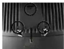
PD-2604UE for KS series
To mount the rear top mount upgrade kit like PD-2604UE on the back of KS series, please apply carefully the 2 small fixation shoulder screws that come along with PD-2604UE to the back of KS series at the screw

natural_image
Two views of a black plastic electronic device showing internal ventilation grilles and mounting holes (no text or symbols visible)hole triangle marked in the 2 upper right pictures. However please do not screw them to the bottom but at a position that is about 1 turn loose from the bottom. Similarly please loosen the screws by 1 turn for some KS models with these 2 screws preinstalled. Arrange the interface cable

natural_image
Interior view of a computer monitor with ventilation grilles and a cable inserted (no visible text or symbols)of the rear top mount upgrade kit to go into the first groove to the right of the left shoulder screw on back of main unit as in the lower picture at right. For host models with Gen 6 super slim base, please stick the 2 attached cable clips at arrowed positions of Gen 6 base in the picture for cable routing when later joining the main unit to Gen 6 base. Hook the rear bracket of the upgrade kit onto the shoulder screws. Slide down the upgrade kit and gently tighten the shoulder screws. Do not overdo the tightening or unrecoverable thread damage will occur.
PD-2603UE for FT series
Open back cover on system
First push in the circled knobs on both sides as in Pix. 3 to remove the back cover.
Remove pole cover
Remove the pole cover on rear edge of the base top cover of FT system by first removing the 2 arrowed screws in Pix. 4 and then pushing the wedge shaped pole cover up.

Pix. 3

natural_image
Close-up of a vintage telephone handset with a circular button and arrow indicator (no visible text or symbols)
natural_image
Close-up of a heat exchanger or cooling unit with cooling fins and a central hub (no visible text or symbols)Pix. 4
Install PD and connect interface cable
Insert the base of PD-2603UE from top of system base with the flat side of the pole base facing the back cover direction and screw back the 2 screws as in Pix. 5. Connect the interface cable to appropriate port.

natural_image
Close-up of a mechanical component with vertical fins and a cylindrical shaft (no visible text or symbols)Pix. 5
PD-2602UE for TP or KS series
Opening the rear connect cover on system
To install PD-2602UE to the base of KS or TP

natural_image
Close-up of a mechanical component with a black arrow pointing to a feature (no visible text or symbols)Pix. 6
systems, the rear connect cover on its base has to be removed as described in the user's manual. The plastic hook plate to remove the rear connect cover in slim base is indicated in Pix. 6 and

natural_image
Interior view of a mechanical device with internal components and an arrow indicating direction (no visible text or symbols)Pix. 7
is indicated in Pix. 7.
Fixing pole display base to system
To fix the PD-2602UE to base of KS or TP systems, please connect the interface cable of PD-2602 through the cable exit in base as in
Pix. 8 a peeping view of pole display joint base bottom to the appropriate port in main unit passing the inside of system base as indicated in the top-view picture Pix. 9. Match the pole base (joint mechanism) to the system rear connect area Fit 2 screws through washers at arrowed points to hold the joint tight.

natural_image
Close-up of a mechanical component with internal wiring and ports (no visible text or symbols)Pix. 8

natural_image
Close-up of a mechanical component with arrows pointing to a circular feature (no visible text or symbols)Pix. 9

natural_image
Close-up of a mechanical component with an arrow pointing to a specific part, showing no visible text or symbols.Pix. 10
PD-2601UE for HT or PB
series
Opening the back cover on system
For ease of PD-2601UE installation operation, the HT main unit or PB system has to be opened with sufficient precautions. First push in the circled knobs on both sides as in Pix. 10 to remove the back cover. Take out the arrow pointed pole cover from it.
Opening the top cover of system
Prepare a piece of clean soft clothe of appropriate size in front of the HT system to prevent damage. Turn the display panel to straight up position. For both HT and PB system, push in the rectangular marked spring button in Pix. 10 on both sides of chassis and raise the rear edge of the top cover.
Find joining points on system
Refer to Pix. 2 that is a picture of the HT or PB chassis near the right bottom corner (as you are facing the HT or PB system from its back) with several portions enlarged around, please find 2 rectangular PD installation holes A on the bottom chassis; 2 circular locating holes B on I/O plate; and 2 circular screw holes C on metal sidewall.

Pix. 11
Find joining points on pole display base

Pix. 12
Take PD-2601UE out of its box and refer to Pix.12 that is a picture of the pole display base unit (lowest part of the PD) with 2 enlarged portions to the right and a slightly enlarged side view picture to the left to find 2 bottom locking lugs A'; 2 short cylindrical locating bosses B' to fit into I/O plate; and 2 plastic screw bosses C' on side. Please note that the PD cable comes out of the bottom end of the base tube yet in the illustration pictures the cable is eliminated for sake of minimum visual confusion.
Insert bottom locking lugs

Turn the pole display base unit opposite to have the bottom locking lugs A' in Pix. 13 facing left and now insert the 2 bottom locking lugs A' on base unit into the 2 rectangular installation holes A on bottom of HT or PB chassis from the right corner with the pole display slightly inclined to the left as in Pix. 13. Please note that both bottom locking lugs A' should be completely inserted and come out of the bottom plate of HT or PB system as emphasized by an arrow in the enlarged portion.
Fit in locating bosses
Please always keep a gentle pressure at the bottom end of pole base (bottom locking lugs A') to the left (away from the sidewall of system chassis) when moving the upper part of pole toward sidewall and matching the 2 short
cylindrical locating bosses B' into 2 round holes B in the I/O plate. Please refer to Pix. 14 to see the 2 locating bosses B' from inside of HT or PB system. Please note the importance of keeping the leftward pressure on bottom end of pole display during the process of turning the pole upright and inserting the locating bosses B' or even when you want to release the locating bosses B' away from I/O plate B and turn the upper end of pole display to left to remove the locking lugs A' from bottom chassis A. Ignorance of this point may damage or even break off the locking lugs A' due to improper torque applied.

Apply sidewall screw
The screw bosses of PD-2601UE base should now align with the screw holes on sidewall of system chassis. Only 1 screw needs to be applied. Use the self-tapping screw that comes with PD-2601UE to fix from external side of sidewall as demonstrated in Pix. 15.

Connect interface cable
Carefully close back the top cover of HT or PB system and connect the interface cable of PD-2601U to appropriate port in system connector area. Then close the back cover of the system.
PD-2600UE
Stand Alone Model:
This instruction is for stand alone model only. Please unpack the inner box of pole display and it easy to find the base, display unit with tube and adaptor separately. Please remove the PE form and bring out the components carefully.

natural_image
Close-up of a black electronic device with a circular button and directional arrows, mounted on a base (no text or symbols visible)Firstly, place the display head and tube on a flat surface and find the cable which in the end of tube. Let this cable pass through the short tube which on the base stand and it shows in the picture at right.
Next, please assemble the display head with tube to the base stand which shows in the right picture. Please pay more attention during the process since there is a hole and a compression lock which are in the two side of tube and marked arrow signs. Aim these two arrow signs nearby compression lock to the holes and push the tube to the end. After hear the “click” sound, the assembly is complete.
Once combine the display head with tube and base stand, please place the pole display as a horizontal position which can easily to check the bottom plate.
Please plug the cable to the connector which showing "To Display" and route the cable as arrowed in the right picture.

natural_image
Close-up of a mechanical component with two white arrows pointing to features (no text or symbols visible)
natural_image
Close-up of a cylindrical mechanical component with a flange and central hole (no text or symbols visible)
natural_image
Close-up of a mechanical assembly with arrows indicating direction (no text or symbols visible)COMMAND EMULATION MODE SETUP
Now please check the back of PD-2600UE/2800UE display series head as in the picture below. There is a small piece of plastic cover for the “DIP switch window”. Slide the cover downward but don’t pull it off otherwise you may have to practice for inserting it back. You can find 6 positions of DIP switches in this window. Adjust for the appropriate interface used by the DIP switches according to below table. Switch position counts from left to right and “ON” means pushed up as indicated in the right part picture below.

DIP SWITCH
- Transmission Protocol
| Switch Position | Interface | |
| 1 | 2 | |
| ON | ON | USB Vendor Class |
| ON | OFF | USB HID Class |
| OFF | ON | Reserved |
| OFF | OFF | Virtual COM Port |
- Emulation Mode
| Switch Position | ||||
| 3 | 4 | 5 | 6 | Mode |
| ON | ON | ON | OFF | UTC |
| ON | ON | OFF | OFF | Aedex |
| ON | OFF | ON | OFF | Noritake |
| ON | OFF | OFF | OFF | Epson |
| OFF | ON | ON | OFF | Futaba |
| OFF | ON | OFF | OFF | ADM |
Note: Switch Position 6 is used for ISP download.
The factory default command mode is set to Noritake mode for normal delivery. Please change it to Epson mode if OPOS or UPOS driver is used for the application program.
COMMAND MODE SELECTION GUIDE
The below table provides some comparison for selection on command mode to be used in the application program if it is not yet determined.
| Mode | ADM | Aedex | Epson | Futaba | Noritake | UTC |
| Cursor | N.A. | N.A. | Invisible | Blinking Block | Blinking Block | Blinking Block (DP) |
| Default mode | N.A. | N.A. | Over/W | V. scroll | Over/W | PT |
| User defined font | N.A. | N.A. | 2 chars | N.A. | 2 chars | 2 chars (PT) |
| Brightness control | NO | NO | YES | YES | YES | YES (DP) |
| Leading code change | NO | YES | NO | YES | YES | YES (PT) |
| Code page select | NO | NO | YES | YES | YES | YES |
| Auto scroll message | NO | NO | NO | YES | YES | YES (PT) |
| Timer clock | NO | NO | YES | NO | NO | YES (PT) |
DRIVER INSTALLATION
Copy the driver and library from Posiflex Product Information CD under Peripheral Drivers & Utilities > PD Series > PD VCOM Driver > USB_VCOM_v510e to your system. Follow instructions given in the file USB Display VCOM Drivers Installing Guide.PDF to send commands (listed later in this manual) and data to the customer display under the programming language.
FOR OPOS APPLICATION:
Find the subfolder UPOS Drivers > OPOS Driver of the Posiflex Product Information CD or download it from Posiflex global website and execute the file “SETUP.EXE” to install the OPOS Control Manager. To add the customer display under OPOS control please set in OPOS Control Manager device name PD3x-Line Display” in the top row.
SPECIFICATION
OPTICAL
Number of digits 20 digits/row, 2 rows
Dot matrix 5 X 7 dots
Digit height 9.03 mm
Digit width 5.25 mm
Display color Yellow Green
Blue or Green (PD-2800 UE)
MECHANICAL
Total Height(PD-2800 UE) 395\~265 mm
Total Width (PD-2800 UE) 200 mm
Total Depth (PD-2800 UE) 116 mm
Total Height (PD-2600) 410 mm
Total Width (PD-2600) 220 mm
Total Depth (PD-2600) 110 mm
Total Height (PD-2601) 392 mm
Total Height (PD-2602) 325 mm
Total Height (PD-2603) 375 mm
Display Head Height 58 mm
Display Head Width 197 mm
Display Head Depth 39.5 mm
Display Head Height(PD-2800 UE) 58.5 mm
Display Head Width(PD-2800 UE) 200 mm
Display Head Depth(PD-2800 UE) 56.5 mm
Case color
Black
ELECTRICAL
Power from interface port of PD-2600UE/2800UE series : + 5VDC 800 mA
ENVIRONMENTAL
Operating temperature 0^ to +40^
Storage temperature -10^ to +60^
Operating humidity 20% to 85%, non-condensing
Storage humidity 5% to 90%, non-condensing
WARNING: If the user opens the pole display housing to make any modification, all the product warranty will be voided.
NOTE: Please refer to Posiflex Product Information CD or visit Posiflex global website for further information when needed.
APPENDIX: COMMAND CODES SUMMARY
| Command | Function | Command | Function | |
| ADM mode | ||||
| 0C | Clear Display | 10 | Write Decimal Point | |
| 0D | Carriage Return | 1E | Write Field 1 | |
| 0E | Write Line 1 | 1F | Write Field 2 | |
| 0F | Write Line 2 | |||
| AEDEX mode | Attention code + Function code + data + CR | |||
| 1 | Display top | 7 | Stop trapping | |
| 2 | Display bottom | 8 | Change attention code | |
| 4 | On going scroll | 9 | Display whole area | |
| 6 | One time scroll | |||
| EPSON mode | ||||
| BS | Move cursor left | US ; | Mark semicolon | |
| HT | Move cursor right | US < | Clear mark | |
| LF | Move cursor down | US E | Set/cancel blinking | |
| HOM | Move cursor home | US T | Set and display counter | |
| CLR | Clear display screen | US X | Brightness adjustment | |
| CR | Move cursor left-most | ESC % | Set/cancel user-defined char. | |
| CAN | Clear cursor line | ESC & | Define user-defined char. | |
| US MD1 | Overwrite mode | ESC ? | Delete user-defined char. | |
| US MD2 | Vertical scroll mode | US @ | Show firmware version | |
| US MD3 | Horizontal scroll mode | ESC = | Select peripheral device | |
| US LF | Move cursor up | ESC t | Select code page table | |
| US CR | Move cursor right-most | US B | Move cursor to bottom | |
| US $ | Move cursor specified | ESC @ | Initialize display | |
| US , | Mark comma | ESC R | International character set | |
| US . | Mark period | US U | Display counter | |
| FUTABA mode | ||||
| 1F | Reset | 10 pp | Digit select | |
| 04 bb | Brightness control | 13 | Cursor on | |
| 1E pp | Change code page | 14 | Cursor off | |
| 1C 0i | International character set | 08 | Back space | |
| 05···0D | Moving sign | 11 09 | Horizontal tab | |
| 06 x1 x2 | Change leading code | 12 09 | Vertical scroll up | |
| 01 | Set pass through flag | 11 0A | Cursor up/down | |
| x1 x2 02 | Clear pass through flag | 12 0A | Line feed | |
| 0D | Carriage return | |||
| NORIRAKE mode | ||||
| 1B 49 | Reset | 1B 54 nn | Cursor blinking Rate | |
| 0E | Clear | 15 | Cursor on | |
| 1B 4C bb | Brightness control | 16 | Cursor off | |
| 1E pp | Change code page | 08 | Back space | |
| 1C 0i | International character set | 11 09 | Horizontal tab | |
| 05···0D | Moving sign | 12 09 | Vertical scroll up | |
| 06 x1 x2 | Change leading code | 11 0A | Cursor up/down | |
| 01 | Set pass through flag | 12 0A | Line feed | |
| x1 x2 02 | Clear pass through flag | OC | Form feed | |
| 1B 48 pp | Digit select | OD | Carriage return | |
| 1B 43 ad x1 ~ x5 | User defined fonts | |||
| UTC Pass through mode | Command [+data] [+CR] | |||
| ESC uA | Top line message | ESC uH | Redefine graphic | |
| ESC uA CR | Clear top line | ESC uIx | Display fonts | |
| ESC uB CR | Clear bottom line | ESC uE | Set/Display time | |
| ESC uB | Bottom line message | ESC utcEx | Change d mode | |
| ESC uD | Continuous scrolling | ESC utcFx | Change RS mode | |
| ESC uF | Top line scroll once | ESC RS * | Direct to pole mode | |
| UTC Direct to pole mode | ||||
| EOT x | Brightness | DC4 | Cursor off | |
| BS | Back spacing | CAN | Clear to end of line | |
| HT | Horizontal tab | EM | Clear to end of display | |
| LF | Line feed | SUB x | Display fonts | |
| CR | Carriage return | ESC d * | Pass thru mode | |
| DLE | Display position | FS | Flashing text start | |
| DC1 | Normal display mode | GS | Flashing text end | |
| DC2 | Vertical scroll mode | RS | Clear display | |
| DC3 | Cursor on | US | Reset display | |
After selecting code page table 19, the Euro Dollar Sign is designated at code
INTERNATIONAL CHARACTER SETS
| Hex code | Country | Hex code | Country |
| 0 | USA | 6 | Italy |
| 1 | France | 7 | Spain |
| 2 | Germany | 8 | Japan |
| 3 | United Kingdom | 9 | Norway |
| 4 | Denmark I | A | Denmark II |
| 5 | Sweden | B | Ex-Jugoslavia |


- PD – 260XUE/2800UE Series User's Manual
- CE CLASS A WARNING
- AVERTISSEMENT CE CLASSE A
- LIMITES DE GARANTIE
- 警告
- CONSIGNES DE SÉCURITÉ
- FEATURES
- INSTALLATION GUIDES
- PD-2800UE
- PD-260XUE
- MECHANICAL INSTALLATION
- Note: Please align the compress lock and the grooves in order to fix the height of customer display.
- PD-2606UE for XP series
- PD-2605UE
- PD-2604UE for KS series
- PD-2603UE for FT series
- Open back cover on system
- Remove pole cover
- Install PD and connect interface cable
- PD-2602UE for TP or KS series
- Opening the rear connect cover on system
- Fixing pole display base to system
- PD-2601UE for HT or PB
- series
- Opening the back cover on system
- Opening the top cover of system
- Find joining points on system
- Find joining points on pole display base
- Insert bottom locking lugs
- Fit in locating bosses
- Apply sidewall screw
- Connect interface cable
- PD-2600UE
- Stand Alone Model:
- COMMAND EMULATION MODE SETUP
- DIP SWITCH
- COMMAND MODE SELECTION GUIDE
- DRIVER INSTALLATION
- FOR OPOS APPLICATION:
- SPECIFICATION
- OPTICAL
- MECHANICAL
- ELECTRICAL
- ENVIRONMENTAL
Brand : Posiflex
Model : PD-2604UE
Category : Point of Sale Terminal