
PD-350UE - Point of Sale Terminal Posiflex - Free user manual and instructions
Find the device manual for free PD-350UE Posiflex in PDF.

| Product Type | LCD Customer Display |
| Brand | Posiflex |
| Model | PD-350UE |
| Display | 2 lines x 20 characters, LCD dark blue character on yellow-green backlight |
| Character Size | 6.0 mm width x 9.66 mm height |
| Dot Matrix | 5 x 7 dots |
| Power Supply | +5 VDC, 300 mA (powered from POS terminal) |
| Interface | USB (selectable modes: USB-HID, USB-Vendor, Virtual COM via DIP switch) |
| Emulation Modes | PST and EPSON command emulation |
| Special Features | Supports Euro and Rupee dollar signs |
| Dimensions (W x H x D) | 197 mm x 58 mm x 39.5 mm |
| Case Color | Black or Ivory |
| Operating Temperature | 0°C to +40°C |
| Storage Temperature | -10°C to +70°C |
| Operating Humidity | 20% to 85% (non-condensing) |
| Storage Humidity | 5% to 90% (non-condensing) |
| Mounting | Rear base pole mount for XT series (2 screws included) |
| Compatibility | Posiflex XT series terminals |
| Warranty | Limited; voids if opened by unauthorized personnel or improper use |
Frequently Asked Questions - PD-350UE Posiflex
where P=0-13 (line1) or 14-27 (line2).
User questions about PD-350UE Posiflex
0 question about this device. Answer the ones you know or ask your own.
Ask a new question about this device
Download the instructions for your Point of Sale Terminal in PDF format for free! Find your manual PD-350UE - Posiflex and take your electronic device back in hand. On this page are published all the documents necessary for the use of your device. PD-350UE by Posiflex.
USER MANUAL PD-350UE Posiflex
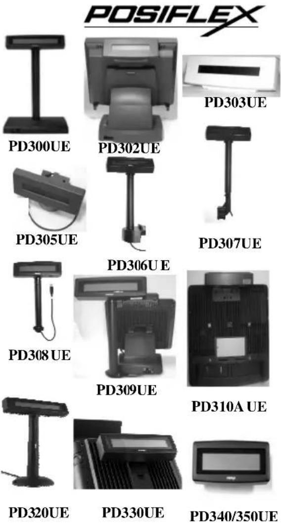
PD-30XUE Series LCD CUSTOMER DISPLAY
FCC Notes:
This equipment generates, uses, and can radiate radio frequency energy and, if not installed and used in accordance with the instructions manual, may cause interference to radio communications. It has been tested an found to comply with limits for a Class A digital device pursuant to subpart J of Part 15 of FCC Rules, which are designed to provide reasonable protection against interference when operated in a commercial environment. Operation of this equipment in a residential area is likely to cause interference in which case the user at his own expense will be required to take whatever measures to correct the interference.
Warranty Limits:
Warranty terminates automatically when any person other than the authorized technicians opens the machine. The user should consult his/her dealer for the problem happened. Warranty voids if the user does not follow the instructions in application of this merchandise. The manufacturer is by no means responsible for any damage or hazard caused by improper application.
About This Manual:
Posiflex has made every effort for the accuracy of the content in this manual. However, Posiflex will assume no liability for any technical inaccuracies or editorial or other errors or omissions contained herein, nor for direct, indirect, incidental, consequential or otherwise damages, including without limitation loss of data or profits, resulting from the furnishing, performance, or use of this material. This information is provided “as is” and Posiflex Technologies, Inc. expressly disclaims any warranties, expressed, implied or statutory, including without limitation implied warranties of merchantability or fitness for particular purpose, good title and against infringement. The information in this manual contains only essential hardware concerns for general user and is subject to change without notice. Posiflex reserves the right to alter product designs, layouts or drivers without notification. The system integrator shall provide applicative notices and arrangement for special options utilizing this product. The user may find the most up to date information of the hardware from web sites: http://www.posiflex.com or http://www.posiflex.com.tw All data should be backed-up prior to the installation of any drive unit or storage peripheral. Posiflex will not be responsible for any loss of data resulting from the use, disuse or misuse of this or any other Posiflex product. All rights are strictly reserved. No part of this documentation may be reproduced, stored in a retrieval system, or transmitted in any form or by any means, electronic, mechanical, photocopying, or otherwise, without prior express written consent from Posiflex Technologies, Inc. the publisher of this documentation.
© Copyright Posiflex Technology, Inc. 2013
All brand and product names and trademark are the property of their respective holders.
P/N: 19430900080
PRODUCT MODEL NUMBER
| Model Name | Spec | Stand Alone | Rear Base Pole Mount(pole default 200mm) | Rear Cover Mount | MEMO |
| PD-300UE | LCD, 2*20 | V (pole default 300mm) | |||
| PD-306UE | " | V | for TP/KS Series | ||
| PD-307UE | " | V | for HT/PB Series | ||
| PD-308UE | " | V | for FT Series | ||
| PD-309UE | " | V | for DT/KS-2010/Gen 6 Base | ||
| PD-310UE | " | V | for 10"/12"/15" KS Series | ||
| PD-310UE-WT | " | V | "(White Color) | ||
| PD-320UE | " | V (pole length adjustable) | |||
| PD-330UE | " | V | for XP Series | ||
| PD-340UE | " | V | for HS Series | ||
| PD-350UE | " | V | for XT Series | ||
| PD-305UE | " | rear base mount lowprofile | for TP/KS Series | ||
| PD-303UE | " | stand alone low profilemodel | |||
| PD-302UE | " | rear top mount | for TP Series |
FEATURES
- LCD (Liquid crystal display) with dark blue character and yellow green back-light
- Two-line display with 20 characters per line
- Easy viewing characters (6.0 mm by 9.66 mm)
- Long life and trouble free operation
- Simple installation
- Selectable command emulation modes including PST and EPSON command emulation modes
- 3 typical USB interface modes (USB-HID Class, USB-Vendor Class, Virtual COM port) selectable by DIP switch
• Euro and Rupee dollar signs supported
INSTALLATION GUIDES
Except for PD-320UE/303UE/300UE which is a stand-alone pole display, only PD-300UE is required with an external power adaptor and needs to come with 12V DC, the other types are powered from the POS terminal.
MECHANICAL INSTALLATION
To fix the rear mount upgrade kit like PD-330UE/340UE/350 UE on the back of XP/XT/HS series, please apply carefully 2 screws that come along with each PD unit.
Please take out the main item with bracket from the package, and fix these items as the following steps:
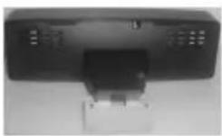
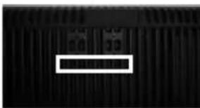
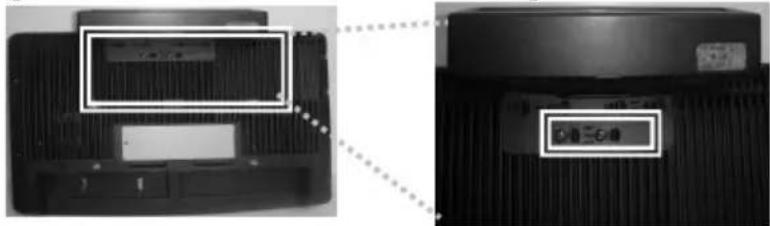
PD-350UE for XT series
A
B

C
A: Hold the PD unit item then turn the screen facing toward you.
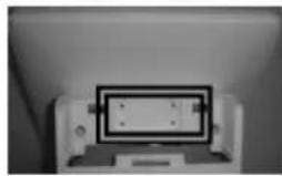
B: Please find the upper 2 of 4 holes on the rear panel of XT series system.
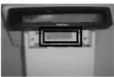
C: Please aim the 2 PD bracket holes to the 2 screw holes on the back cover of XT main unit and fasten them to fix PD on the XT series.
PD-340UE for HS series
A

B

C
A: Hold the PD unit item then turn the screen facing toward you.
B: Please find the 4 holes on the rear panel of HS series system.
C: Please aim the 4 PD bracket holes to the 4 screw holes on the back cover of HS main unit and fasten them to fix PD on the HS series.
PD-330UE for XP series
A
B

C
D
A: Please take the bracket and find the side of two screws holes with mistake-proofing holes and aim to the PD main unit.
B: Hold the PD unit item then turn the screen facing toward you.
C: Please route the PD cable into the cannelure between fins and near the screw hole.
D: Please aim the 3 screw holes to the back cover of XP-2000 series
main unit and fasten them to fix PD on the XP series.
PD-320UE
For this type of mechanical design of standalone customer pole display, it can operate straight away and no needs to assemble with any other host system. Nevertheless, it also can fix on the counter or any place when it needs to be fixed. The following pictures A to D will describe such as how to adjust the height of the pole and how to fasten the PD-320UE in a flat surface.
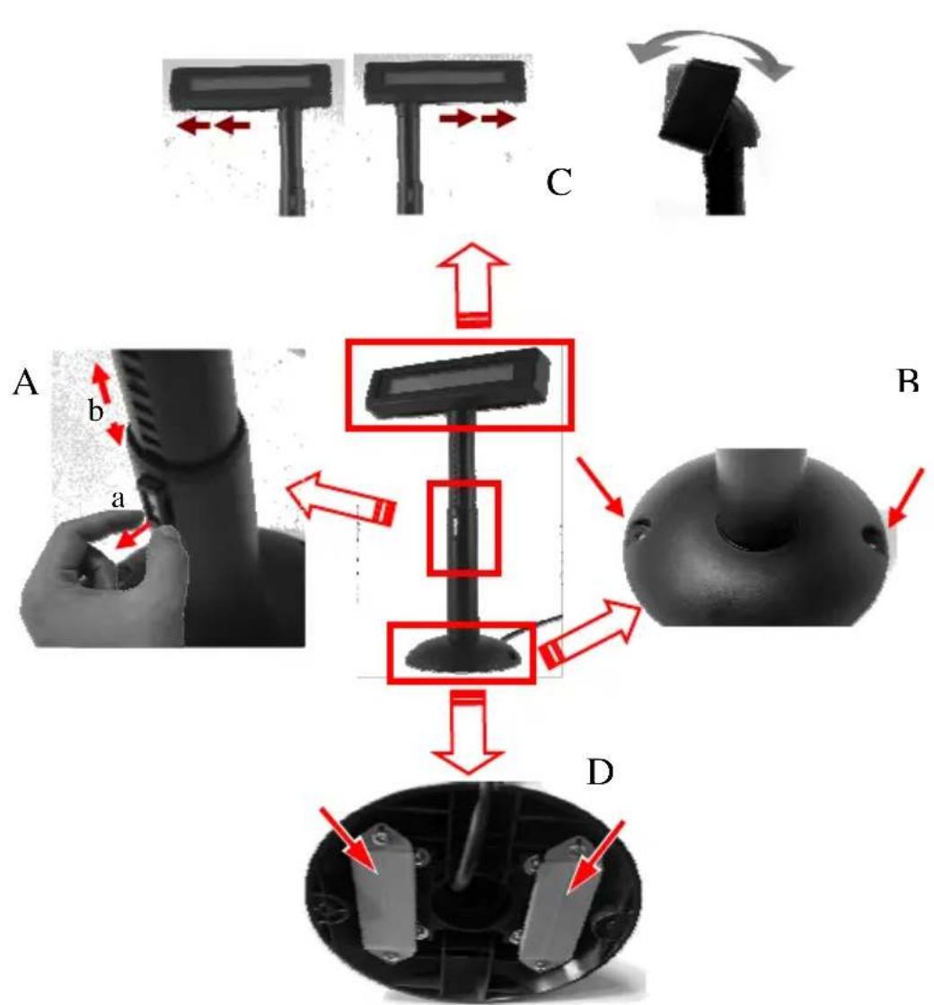
Picture A is going to describe how to adjust the height of customer displays:
a) Please hold the compression lock by using thumb and index finger and pull out the lock.
b) Please use the other hand to hold the tube and extend to higher or lower profile of display's height. After adjusting to a satisfactory height, please push back the compress lock to fix the tube.
Note: Please align the compress lock and the grooves in order to fix the height of customer display.
Picture B is going to show how to screw PD-320UE in a flat surface. In the base stand of PD-320UE, there are two screw holes for user to fix the customer display. Please choose a flat surface to fix the customer display in
order to keep the PD-320UE stable. (The screws come with PD-320UE and in the carton.)
Picture C, the display head of PD-320UE can move as horizontal direction to the right or left, as well as front-rear adjustable degree from 15° or 23°.
Picture D, there are two plates in the bottom of customer display which can be used for Velcro and provides more stability without screws fixed. (The velcro comes with PD-320UE and in the carton)
PD-310AUE for KS series
To mount the rear top mount upgrade kit like PD-310AUE on the back of KS series, please apply carefully 2 screws that come along with PD-310AUE to the back of KS series at the screw hole triangle marked in the upper right picture. However

please do not screw them to the bottom but at a position that is about 1 turn loose from the bottom. Similarly please loosen the screws by 1 turn for some KS models with these 2 screws preinstalled.
For PD-310AUE fixed to KS series, please kindly follow steps below: A) Find the lower 2 holes as indicated on the main unit.
B) Aim the 2 screws into the 2 holes above, together with PD-310AUE rear top mount bracket numbered in inch pairs indicated below.
For host models with Gen 6 super slim base, please stick the 2 attached cable clips at arrowed positions of Gen 6 base in the picture for cable routing when later joining the main unit to Gen 6 base. Hook the rear bracket of the upgrade kit onto the shoulder screws. Slide down the upgrade kit and gently tighten the shoulder screws.
Base for KS-2010
Do not overdo the tightening or unrecoverable thread damage will occur.
PD-309UE for KS or DT series
The PD-309UE can be attached to the corner in bottom plate of the KS series,
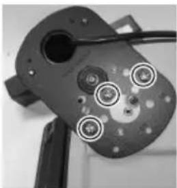
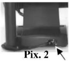
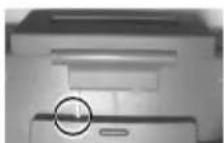
with slim base, DT series and Gen.6 & 5 base of KS series. It takes examples of this LCD customer display to fix in the KS series, and DT series. Refer to the pictures in Pix.1 at right. Use the 3 attached screws to fix the metal base plate of the PD to bottom of mini slim base or DT-20X at the circled positions. For mini slim base, connect the interface cable to go into the base through cable exit arrowed in Pix.2 at right to the main unit. For DT-20X arrange the interface cable to go through under bottom to connector area arrowed in Pix.1 at above right.
CAUTION: There are self-tapping screws for PD-309UE when available in Gen. 5 base stand and please aim to the holes which marked “DT” as shown in the upper picture Pix.1. Other Bing Head Screws are available when fixed in KS series, DT series and Gen.6 base stand of KS series.
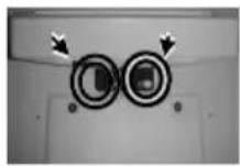
PD-308UE for FT series:
-
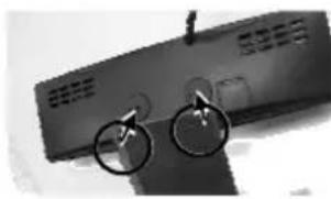
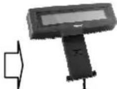
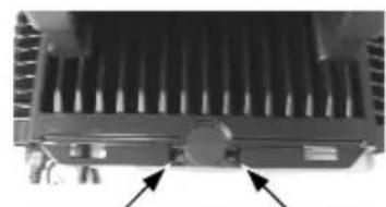
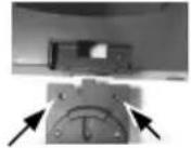
To install PD-308UE onto FT series host system, the back cover of FT system base has to be opened. First push in the circled knobs on both sides as in the right pictures to remove the back cover.
-
Remove the pole cover on rear edge of the base top cover of FT system by first removing the 2 arrowed screws in the left picture and then pushing the wedge shaped pole cover up.
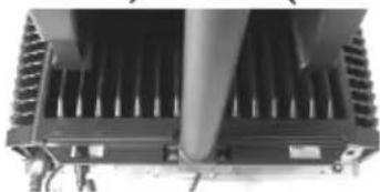
-
Insert the base of PD-308UE from top of FT system base and screw back the 2 screws as in the right picture. Connect the interface cable to appropriate port.

Stand Alone Model:
This instruction is for stand alone model only. Please unpack the inner box of pole display and it is easy to find the base, display unit with tube and adaptor separately. Please remove the PE foam and bring out the components carefully.
Firstly, place the display head and tube on a flat surface and find the cable in the end of tube. Let this cable pass through the short tube on the base stand, as shown in the picture at right.
Next, please assemble the display head with tube to the base stand which shows in the right picture. Please pay more attention during the process since there are a hole and a compression lock which are in the two sides of tube and marked arrow signs. Aim these two arrowed signs nearby compression lock to tube to the end. After hearing the “click” sound, the assembly is complete.

Once combine the display head with tube and base stand, please place the pole display as a horizontal position which can be easily checked with the bottom plate.
Please plug the cable to the connector which shows "To Display" and route the cable as arrowed in the right picture.
PD-307UE for HT series:
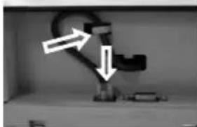
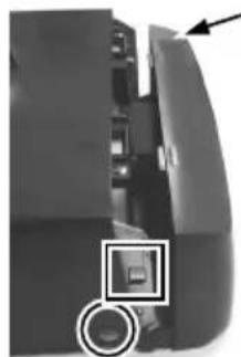
- For ease of PD-307UE installation operation, the HT main unit or PB system has to be opened with sufficient precautions. First push in the circled knobs on both sides as in the right picture to remove the back cover. Take out the arrow pointed pole cover from it.
-
Prepare a piece of clean soft clothe of appropriate size in front of the HT system to prevent damage against the display panel. Turn the display panel to straight up position. For both HT and PB system, push in the rectangular marked spring button in the same picture mentioned above on both sides of chassis and raise the rear edge of the top cover.
-
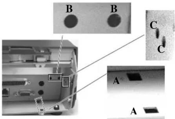
Refer to the picture at right of the HT or PB chassis near the right bottom corner (as you are facing the HT or PB system from its back) with 3 enlarged portions around, please find 2 rectangular PD installation holes A on the bottom chassis; 2 circular locating holes B on I/O plate; and 2 circular screw holes C on metal sidewall.
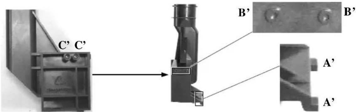
- Please then refer to the pictures below for the base unit (lowest part) of PD-307UE with 2 enlarged portions to the right and a slightly enlarged side view picture to the left to find 2 bottom locking lugs A'; 2 short cylindrical locating bosses B' to fit into I/O plate; and 2 plastic screw bosses C' on side. Please note that the PD cable comes out of the bottom end of the base tube yet in the illustration pictures the cable is eliminated for the sake of minimum visual confusion.
- Turn the pole display base unit opposite to have the bottom locking lugs A' facing left and now insert the 2 bottom locking lugs A' on base unit into the 2 rectangular installation holes A on bottom of HT or PB chassis
from the right corner with the pole display slightly inclined to the left as in the upper picture at right. Please note that both bottom locking lugs A' should be completely inserted and come out of the bottom plate of HT or PB system as emphasized by an arrow in the enlarged portion in lower right.

Please always keep a gentle pressure at the bottom end of pole base (bottom locking lugs A') to the left (away from the sidewall of system chassis) when moving the upper part of pole toward sidewall as in the left picture.

- Please refer to the right picture taken from inside of HT or PB system to show that the 2 short cylindrical locating bosses B' should match into 2 round holes B in the I/O plate. The bosse are shown in the enlarged portion.
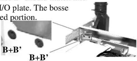
- Please note the importance of keeping the leftward pressure on bottom end of pole display during the process of turning the pole upright and inserting the locating bosses B' or even when you want to release the locating bosses B' away from I/O plate B and turn the upper end of pole
display to the left to remove the locking lugs A' from bottom chassis A. Ignorance of this point may damage or even break off the locking lugs A' due to improper torque applied.

-
The screw bosses on base of PD-307UE should now align with the screw holes on sidewall of system chassis. Only 1 screw needs to be applied. Use the self-tapping screw that comes with PD-307UE to fix from external side of sidewall as demonstrated in the right picture.
-
Carefully close back the top cover of HT or PB system and connect the interface cable of PD-307UE to appropriate port in system connector area. Then close the back cover of the system.
PD-305UE, PD-306UE for KS or TP series:
- Remove rear connect cover of the KS or TP series terminal system from the base per instruction of the terminal system.

- Have the cable of PD-305UE, PD-306UE that comes
Cable Exit
out of its base joint to enter the base of host system through the cable exit to connect to the main unit.
- Match the base joint of PD-305UE or PD-306UE to the system rear connect area. Fit 2 screws through washers at arrowed points in the right
pictures to hold the joint tight.
PD-305UE

PD-306UE
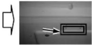
PD-303UE:
-
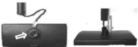
Adhere the two pieces of EVA tape on the metal plates at bottom as indicated in picture at right. Peel off the protective covers of the tape to stick PD303UE series on a flat and clean surface.
-
Apply the screws at 2 arrows in the right picture for firm fixation on counter if necessary.

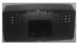
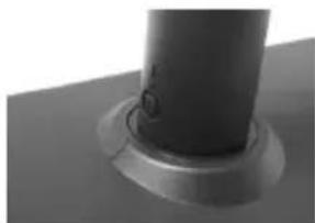
PD-302UE for TP series:
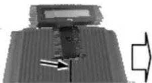
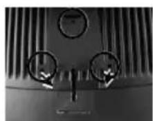
- Aim the bottom center cavity of PD302UE series toward the latch stub at rear of TP series main unit as circled in the right picture. Then aim both metal and
plastic hooks at rear of the PD302UE series toward the suitable ventilation openings on top rear of the main unit. Please use a Phillips head (“+” sign) screw driver to fasten the screws on the metal hook but not to overdo it so that the metal hooks hold the ribs of the v from inside.

-
Plug the other USB end of PD-302UE at the USB connector of TP.
-
Route the cable to go through the notch on back of the stand assembly of touch terminal as indicated in the picture. Reassemble the main unit and stand assembly.
(Guidance for future un-installation: Please use screw driver to release the metal hook before removing PD302UE from the ventilation holes.)
PD-300UE:
In base of stand alone models, looking from rear side of the bottom, the connector area will look like below:
For PD-300UE model:
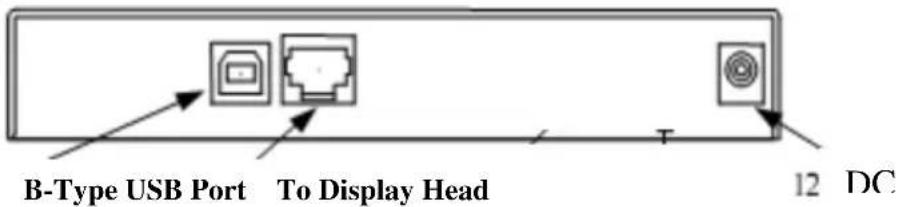
The RJ45 type modular connector is for VFD display purpose and also already occupied. Connect the “B” type plug of the interface cable to the base USB connector and the “A” type end to USB port of the host. Insert the DC plug of 12V DC power adaptor to the “12V DC IN” jack in the pole base.
You may now place the base on a horizontal surface and prepare to power on and adjust the direction of the display head for best viewing effect in application.
COMMAND EMULATION MODE SETUP
(FOR PD-300UE series)
Now please check the back of PD-300UE series display head as in the picture below. There is a small piece of plastic cover for the “DIP switch window”. Slide the cover downward but don’t pull it off otherwise you may have to practice for inserting it back. You can find 4 positions of DIP switches in this window. Adjust for the appropriate interface used by the DIP switch according to below table. Switch position counts from left to right and “ON” means pushed up as indicated in the below picture below.

| Switch Position | Interface | |||
| 1 2 3 4 | ||||
| ON ON OFF OFF USB Vendor Class | ||||
| ON OFF OFF OFF USB HID Class | ||||
| OFF ON OFF OFF Reserved | ||||
| OFF | OFF OFF OFF | Virtual COM Port | ||
The factory default command mode is set to Epson mode for normal delivery. Please change it to Epson mode if OPOS or UPOS driver is used for Page 12
the application program.
DRIVER INSTALLATION
Copy the driver and library from Posiflex Product Information CD under Peripheral Drivers & Utilities > PD Series > PD VCOM Driver >
USB_VCOM_v510e to your system. Follow instructions given in the file USB Display VCOM Drivers Installing Guide.PDF to send commands (listed later in this manual) and data to the customer display under the programming language.
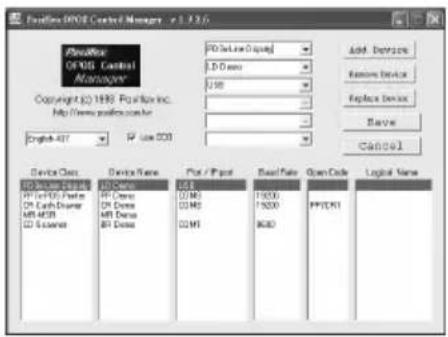
FOR OPOS APPLICATION:
Find the subfolder UPOS Drivers > OPOS
Driver of the Posiflex Product Information CD or download it from web site http://www.posiflex.com/english/03_support/03_download.php?prod=ajc=&cate=ajY= and execute the file "SETUP.EXE" to install the OPOS Control Manager. To add the customer display under OPOS control please set in OPOS Control Manager device name "PD3x-Line Display" in the top row.
SPECIFICATION
OPTICAL
Number of digits 20 digits/row, 2 rows
Dot matrix 5 X 7 dots
Digit height 9.66mm
Digit width 6.0 mm
Display color Yellow Green,
Dark Blue
MECHANICAL
Display Head Height 58 mm (PD-309UE/310UE/340UE/350UE) 59 mm (PD-320UE)
Display Head Width 197 mm (PD-309UE/310UE/340UE/350UE) 200 mm (PD-320UE)
Display Head Depth 93 mm (PD-340UE) 39.5 mm (PD-
309UE/310UE/350UE/330UE)
57 mm(PD-320UE)
Display Head Size for
PD-302 UE/303UE/305UE
217 mm (W) x 80.5 mm (H) x 28.5 mm (D)
PD-306UE \~ 308UE
196.7 mm (W) x 57.5 mm (H) x 39.6 mm (D)
PD-300UE
222 mm (W) x 410mm (H) x 112 mm (D)
Case color Black or Ivory
ELECTRICAL
Total Power Consumption: + 5VDC 300mA.
ENVIRONMENTAL
Operating temperature 0° to +40°C
Storage temperature -10° to +70°C
Operating humidity 20% to 85%, non-condensing
Storage humidity 5% to 90%, non-condensing
WARNING: If the user opens the pole display housing to make any modification, all the product warranty will be voided.
NOTE: Please refer to Posiflex Product Information CD or visit our web http://www/posiflex.com.tw for further information when needed.
APPENDIX
APPLICABLE COMMANDS
| EPSON COMMAND MODE (POWER ON DEFAULT): | ||
| NAME | HEX CODES | FUNCTION |
| BS <08> | Move Cursor Left | |
| HT <09> | Move Cursor Right | |
| LF <0A> | Move Cursor Down | |
| HOM <0B> | Move Cursor | To Home Position |
| CLR <0C> | Clear Display | Screen |
| CR <0D> | Move Cursor | To Left Most Position |
| CAN <18> | Clear Cursor Line | |
| ESC = | <1B><3D><04> | Set PST command mode |
| ESC @ | <1B><40> | Initialize Display |
| ESC t | <1B><74><n> | Disable / Enable Euro Dollar Signn = 0, 13hDisable/Enable Rupee Dollar Signn= 0, 60h |
| US MD1 | <1F><01> Specify | Overwrite Mode |
| US MD2 | <1F><02> Specify | Vertical Scroll Mode |
| US MD3 | <1F><03> Specify | Horizontal Scroll Mode |
| US LF | <1F><0A> Move Cursor Up | |
| US CR | <1F><0D> Move | Cursor To Right Most Position |
| US $ | <1F><24><n><m> | Move Cursor To Specified Positionn = 1 ~ 20m = 1, 2 |
| US @ | <1F><40> Show Version | |
| US B | <1F><42> Move Cursor | Cursor To Bottom Position |
| US C | <1F><43><n>Cursor On / Off, n = 1, 0 | |
| US E | <1F><45><n> | Blink Display Screenn = 0 ~ 255 |
| PST COMMAND MODE: | |
| HEX CODES FUNCTION | |
| <06><N1><N2> Change Leading Code | |
| <14><01> Wraparound Mode (Default) | |
| <14><02> Vertical Scroll Mode | |
| <14><03> Insert Mode | |
| <14><04> Overwrite Mode (Default) | |
| <14><08> Back Space | |
| <14><09> Move Cursor Right | |
| <14><0A> Move Cursor Down | |
| <14><0B> Move Cursor Left | |
| <14><0C> Delete Character | |
| <14><0D> Move Cursor To Left Most Position | |
| <14><0E> Clear Display | |
| <14><10> Clear Line 1 | |
| <14><11> Clear Line 2 | |
| <14><12> Cursor Block Mode | |
| <14><13> Cursor Under Line Mode | |
| <14><15><02> Clear Pass Through Flag | |
| <14><16> Switch To Epson Mode | |
| <14><17> Cursor On | |
| <14><18> Cursor Off | |
| <14><19> Reset | |
| <14><1A><P> Move | Move Cursor To Position P (P=0~13,14~27h) |
| <14><1B> Move | Cursor To Rightmost Position Of Line 1 |
| <14><1C> Move | Cursor To Rightmost Position Of Line 2 |
After selecting code page table 19, the Euro Dollar Sign is designated at code
After selecting code page table 96, the Rupee Dollar Sign is designated at code <60>h.


- PD-30XUE SERIES LCD CUSTOMER DISPLAY
- FCC NOTES
- WARRANTY LIMITS
- ABOUT THIS MANUAL
- © COPYRIGHT POSIFLEX TECHNOLOGY, INC. 2013
- FEATURES
- INSTALLATION GUIDES
- MECHANICAL INSTALLATION
- PD-320UE
- PD-310AUE FOR KS SERIES
- DO NOT OVERDO THE TIGHTENING OR UNRECOVERABLE THREAD DAMAGE WILL OCCUR
- PD-309UE FOR KS OR DT SERIES
- PD-308UE FOR FT SERIES
- STAND ALONE MODEL
- PD-307UE FOR HT SERIES
- PD-305UE, PD-306UE FOR KS OR TP SERIES
- CABLE EXIT
- PD-303UE
- PD-302UE FOR TP SERIES
- PD-300UE
- COMMAND EMULATION MODE SETUP
- (FOR PD-300UE SERIES)
- DRIVER INSTALLATION
- FOR OPOS APPLICATION
- SPECIFICATION
- OPTICAL
- MECHANICAL
- ELECTRICAL
- ENVIRONMENTAL
- APPENDIX
Brand : Posiflex
Model : PD-350UE
Category : Point of Sale Terminal