SLU-175 - Connectique électrique Ilsco - Free user manual and instructions
Find the device manual for free SLU-175 Ilsco in PDF.

| Product Type | Electrical Connector Lug |
| Model | SLU-175 |
| Brand | Ilsco |
| Material | High-Conductivity Copper (Tin-Plated) |
| Voltage Rating | 600 V |
| Current Rating | 175 A |
| Wire Size Range | #6 AWG to 1/0 AWG |
| Number of Holes | 1 |
| Stud Size | 3/8" or 1/2" |
| Dimensions | 3.5" x 1.2" x 0.6" |
| Weight | 0.5 lb (approx.) |
| Operating Temperature | -40°C to 105°C |
| Standards | UL Listed, CSA Certified |
| Primary Function | Secure connection of conductors to electrical panels, switches, and bus bars |
| Installation | Requires proper torque wrench for screw tightening |
| Maintenance | Periodic inspection for corrosion; clean with dry cloth |
| Safety | Always de-energize circuit before installation |
| Spare Parts | Replacement screws and washers available from Ilsco |
| Repairability | Non-repairable; replace if damaged |
Frequently Asked Questions - SLU-175 Ilsco
User questions about SLU-175 Ilsco
0 question about this device. Answer the ones you know or ask your own.
Ask a new question about this device
Download the instructions for your Connectique électrique in PDF format for free! Find your manual SLU-175 - Ilsco and take your electronic device back in hand. On this page are published all the documents necessary for the use of your device. SLU-175 by Ilsco.
USER MANUAL SLU-175 Ilsco
Connector Installation Guide Compression and Mechanical Connectors
natural_image
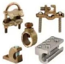
Collection of metallic electrical connectors and mounting brackets, including a multi-pin connector and two labeled metal blocks (no readable text or symbols)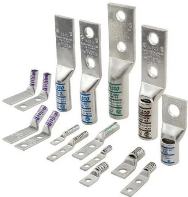
natural_image
Collection of various LSCO electrical fuse components with metal brackets and terminal connectors (no visible text or symbols)Typical Cross Section of a Compression Connector Before Installation
natural_image
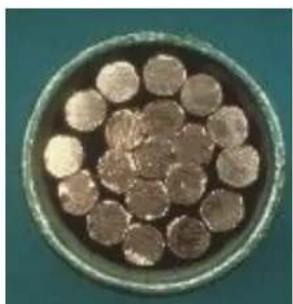
Circular arrangement of small, round objects resembling biological cells or particles, with no visible text or symbols.Before compression, a typical cross section of cable consists of 75% metal and 25% air
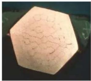
Typical Cross Section of a Compression Connector After Installation
After compression, little air is left.
natural_image
Hexagonal-shaped object with crack-like texture, possibly a geological or material sample (no visible text or symbols)
natural_image
Close-up of a brown, irregularly shaped object with visible internal structure against a black background (no text or symbols)
Single & Dual Mounting holes

Flared-End

natural_image
Metallic cylindrical component with two holes, no visible text or markings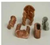
C-Taps Narrow Tongue

Splices
H-Taps
natural_image
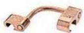
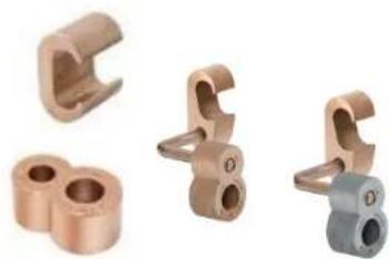
Four different copper-colored mechanical clamps or fittings, shown from different angles (no text or symbols visible)Grid Grounding

text_image
PUNPLE DIE 54 40 ANG 30 FLX 30 30 30 30 30 30 30 30 30 30 30 30 30 30 30 30 30 30 30 30 30 30 30 30 30 30 30 30 30 30 30 30 30 301. Determine Proper Connector For Cable
- Conductor size and CU = Copper conductors only
- Conductor size and "AL9" = Aluminum conductors only
- Conductor size and "AL9CU" = Aluminum or Copper conductors
- Match size and type of conductor to proper lug
Note: Consult manufacturers instructions on whether fine stranded conductors or welding cable conductor types may be used.
text_image
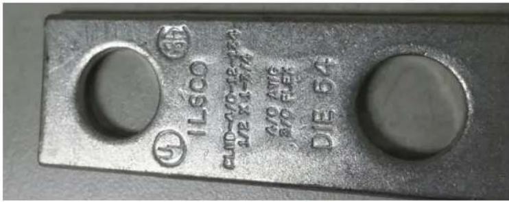
IL500 CUP-40-12-17A DIE 64 30 X1-FN 30 X1-FN DIE 64Marking Information on Connectors:
- Manufacturer
- Wire Size
- Wire material- CU, AL, or AL9CU (indicates Dual Rating and 90°C)
• Optional Crimp Indicator Bands - Listing Information

text_image
ILSCO PURPLE DIE 54 4/0 AWG 3/0 FLEX SF. 4L2. Strip and Properly Prepare Cable
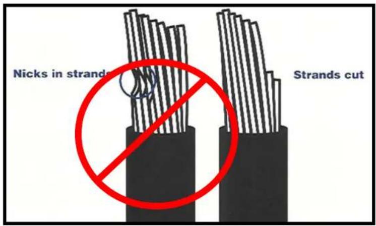
- Strip insulation carefully to avoid nicking strands.
- Strip to proper length so conductor can be fully inserted.
- Refer to manufacturer's instructions for strip length.
- Most connectors are suitable for one conductor. Never install more than one conductor unless specifically allowed by the manufacturer's instructions.
Aluminum Conductor –
- Brush the stripped portion of the conductor to remove oxide film using a stainless steel wire brush.
- Apply oxide inhibitor compound and wire brush into the stranding. Do not remove pre-filled inhibitor from the barrel.
Installation Guide for Compression

text_image
Nicks in strands Strands cut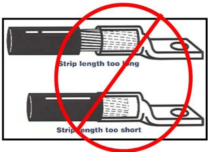
text_image
Strip length too long Strip length too short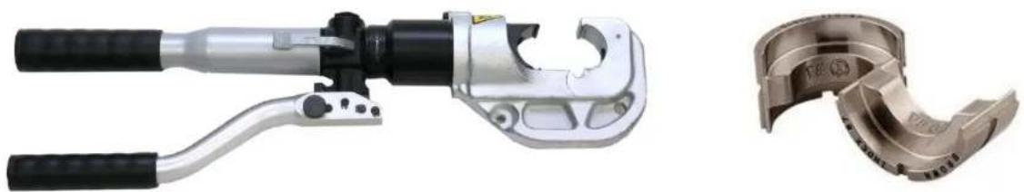
natural_image
Two metal pipe crimping tools shown side by side: a handheld tool and a mechanical clamp (no text or symbols visible)3. Select proper installing die tool
- Always refer to the connector manufacturer's instructions for the proper compression die that is intended for the connector.
- Manufacturer's may use colored bands or dots that correspond to color markings on dies.
- Manufacturer's may use die code number marked or stamped on the connector.
- Knurls may be used in place of colored bands.

text_image
When making multiple crimps, make the first crimp nearest the tongue and work towards the barrel end. Barrel Tongue DIE 54 PUPPL 3/0 FLEX 2nd crimp 1st crimp Die location for compression ILSCO CT - 350 SR 250 KONIH 150 ULM 252 PLEX RED DIE 71 2nd Crimps 1st Crimps-
Locate tool with correct die in proper position on connector and activate tool
-
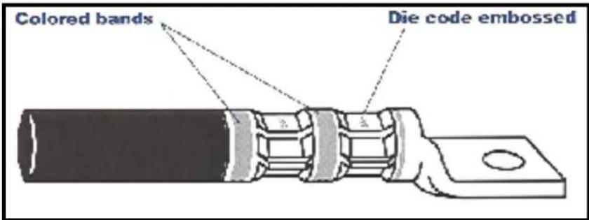
Connectors that are banded with colored stripes to indicate number and location of each crimp.
- Connectors may also be marked with the die code number at each compression location.
- Follow manufacturers instructions whether to crimp on the colored bands or between the colored bands.
When making multiple crimps, make the first crimp nearest the tongue and work towards the barrel end.
text_image
Colored bands Die code embossed4. Continued....
When crimped, the die code number or other marking will be embossed on connector for easy inspection to determine if correct die and connector combination were used.

natural_image
Four different types of manual crimping tools shown: IGBT-6, IVTB-6-ALIO-CRMP Head, wrench, and tap wrench (no text or symbols on the devices themselves)Select proper installing dieless tool
- Crimp as directed by the manufacturer's instructions.
5. Connector Securement
natural_image
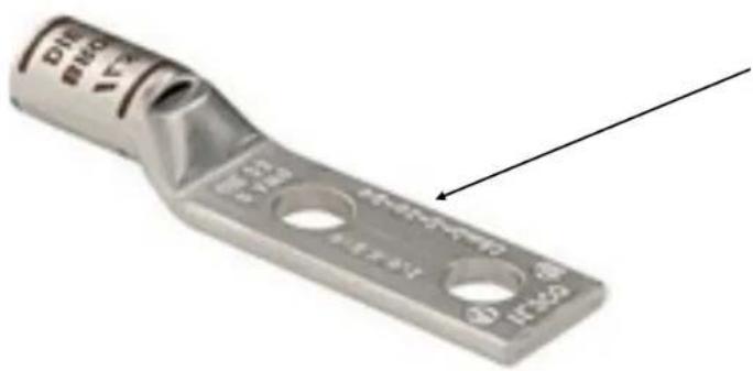
Metal electrical fuse component with three circular holes and a labeled end (no text or symbols on the body itself)Use a 2-hole connector if there is a concern for twisting the connection.

natural_image
Metallic square mechanical component with a hexagonal bolt and circular opening (no visible text or symbols)
natural_image
Three different types of metal fasteners or bolts, shown from different angles (no text or symbols visible)
text_image
Double Conductor Lug
text_image
Single Conductor Lug
text_image
Overhead Transformer
text_image
Double Conductor Lug, NEMA Pad
text_image
Copper Single Conductor Lug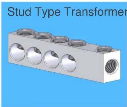
natural_image
3D rendering of a Stud Type Transformer with six circular components and threaded end (no text or symbols on the diagram itself)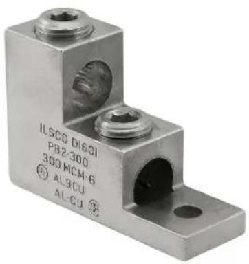
text_image
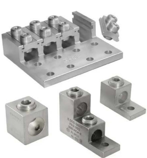
ILSCO DI601 PB2-300 300 MCM-6 AL9CU AL-CU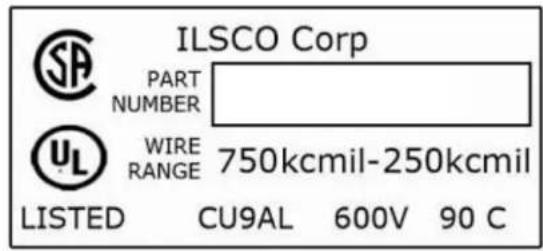
text_image
ILSCO Corp PART NUMBER WIRE RANGE 750kcmil-250kcmil LISTED CU9AL 600V 90 CMarking Information on Connectors:
- Manufacturer's name or Symbol
- Wire Size or range
- Wire material- CU, AL, or Both
• Temperature Rating if applicable
• AL9CU Shows Dual Rating (Al & Cu) and 90°C - UL and/or CSA if it is a listed connector
natural_image
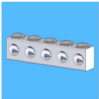
3D rendering of a six-pin mechanical component with circular cutouts, set against a solid blue background (no text or symbols)- Unlike Compression connectors, mechanical connectors typically take a range of conductors. It is important to check that the cable falls within the cable range listed on the connector.
- If the connector is intended to be used on a bus, pad or equipment, mount the connector and tighten the mounting hardware per the manufacturer's specifications.
text_image
Nicks in strands Strands cut3.Strip and Properly Prepare Cable
- Strip insulation carefully to avoid nicking strands
- Strip to proper length so conductors can be fully inserted
• Refer to manufacturers instructions for strip length
• Aluminum Conductor –
- Brush the stripped portion of the conductor to remove oxide film with a stainless steel wire brush. Apply oxide inhibitor compound and wire brush into the stranding

natural_image
Mechanical assembly diagram showing a threaded component inserted into a housing, with no visible text or symbols.-
Insert the conductor(s) and tighten all set screws per the manufacturer's recommendations.
-
Do not retighten after properly torqued.
- Most connectors are suitable for one conductor. Never install more than one conductor unless specifically allowed by the manufacturers instructions.
- Use the mounting bolt size as recommended by the manufacturer.
• Generally used as taps.
- If conductors are different materials, a spacer bar is included. Aluminum conductor should always be positioned on top.
natural_image
Close-up of a metallic bolt and nut assembly (no text or symbols visible)• Voltage Rating (Insulated Only)
- 300 volts
- 600 volts
• 1000 volts signs/luminaires
• Note: NOT MARKED
- Non-insulated listed connectors are suitable for 2,000 volts. They may be used over 2,000 volts up to 35,000 volts where the effects of corona have been investigated.
• Non-insulated Temperature Rating
- 75^ C - Use the connector at 75^ C ampacity
- 90^ C - Use the connector at 90^ C ampacity
- Higher temp rated conductors at higher ambient temperatures may be used as long as the ampacity levels are used per the connector rating.
- Use the NEC® to obtain the conductor ampacity ratings.
• Insulated Temperature Rating
- Never exceed the temperature rating of an insulated connector. See Packaging or Product for the marking.
Conductor Material
- AL 9 Aluminum 90^ C
- AL9CU CU9AL Aluminum/Copper 90°C
- AL7 Aluminum 75°C
- AL7CU CU7AL Aluminum/Copper 75°C
AL9CU

text_image
ILSCO 02950 2/0-400MCM ALECU ML-CUInstallation Guide for Grounding
- Grounding
- DB Direct Burial
- The connector is suitable for direct burial in the soil or embedded in concrete.

natural_image
Close-up of a metal pipe clamp securing copper wires with a bolt (no text or symbols visible)
text_image
DB = Direct Burial Suitable Conductor Compression Die Information Rod size InformationLook for the product markings for suitability for attachment to rods, pipe, and concrete encased reinforcement steel.

text_image
PAT PEND
natural_image
Close-up of a brass-colored mechanical component with four protrusions (no text or symbols visible)
natural_image
Close-up of a metallic mechanical component with hexagonal top and engraved text (no readable document content)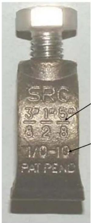
text_image
SRC 3/8 1/2 5/8 1/0-10 PAT PENDRod size
Conductor size
ILSCO
connections
matter

text_image
BUST TAW GND PAT PEND JRDDirect burial
Conductor size
Rebar size
natural_image
3D diagram of a mechanical assembly with multiple black rods and yellow directional arrows indicating force or movement (no text or symbols)Parallel Feed - 4 smaller load wires in between

natural_image
3D rendering of four black cylindrical components with yellow directional arrows, mounted on a metal bracket (no text or symbols)Three Parallel Feeds, Three parallel Loads
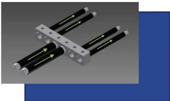
natural_image
3D diagram of mechanical components with directional arrows indicating movement (no text or symbols)Parallel Feeds, 4 Load Wires on outer two holes

natural_image
3D diagram of four black cylindrical components with yellow directional arrows, connected by a gray bracket (no text or symbols)Two Parallel Feeds, 4 Load Wires - Load wires on outer edges and in the center two holes
Incorrect application

natural_image
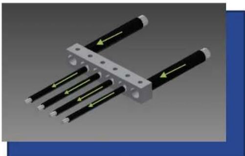
3D diagram of a mechanical assembly with black cylindrical components and green directional arrows indicating motion (no text or symbols)Parallel Feeds one end, 4 Load Wires opposite end
Typical Failure Modes in Sealed Connectors
text_image
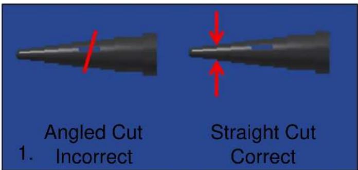
Angled Cut 1. Incorrect Straight Cut Correct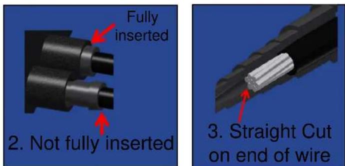
text_image
Fully inserted 2. Not fully inserted 3. Straight Cut on end of wire- Wire plug cut at angle
- Wire plug or screw plug not fully inserted
- Angled cut on end of wire
- Missing wire plugs or screw plugs
- Short/long insulation strip length
Typical Failure Modes

text_image
Screw Plugs Wire Plugs 4. Missing wire plugs or screw plugs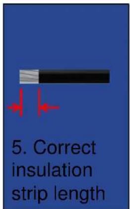
text_image
5. Correct insulation strip lengthSafety Standards
Wire Connectors
- UL 486A-486B
• CSA C22.2 No. 65
• ANCE NMX-J-543
• ANSI C119.1, C119.4, C119.5, C119.6
Splicing Wire Connectors
- UL 486C
• CSA C22.2 No. 188
• ANCE NMX-J-548
natural_image
Close-up of a metallic cylindrical component with a flanged end and circular hole (no visible text or symbols)
Fig. 1

Fig. 2

Fig. 3

Fig. 4


natural_image
Close-up of a metallic electrical connector with two screw holes (no text or symbols visible)Grounding and Bonding Equipment
- UL 467
• CSA C22.2 No. 41 - ANCE NMX-J-567