COR540SL - Range hood Caple - Free user manual and instructions
Find the device manual for free COR540SL Caple in PDF.

User questions about COR540SL Caple
0 question about this device. Answer the ones you know or ask your own.
Ask a new question about this device
Download the instructions for your Range hood in PDF format for free! Find your manual COR540SL - Caple and take your electronic device back in hand. On this page are published all the documents necessary for the use of your device. COR540SL by Caple.
USER MANUAL COR540SL Caple
Ceiling Hood Instruction Manual
COR540SL

natural_image
Pure diagram of a ceiling lamp with a circular top and ring base, no text or symbols present.CONTENTS
Warnings 3
Environmental Protection 8
Opening the Panel 10
Installation 11
Remote Control 14
Timing
17
Cleaning and Maintenance 18
Caple Contact Details 20
WARNINGS
The appliance is not intended for use by young children or infirm persons without supervision. Young children should be supervised to ensure they do not play with the appliance.
The extracted air can't be conveyed through or into a duct used to let out fumes from appliances fed by energy other than electric power (eg. centralized heating, radiators, water heaters, etc.).
To evacuate the air outlet, please comply with the pertaining rules given by competent authorities.
-Provide the room with an adequate aeration when a cooker hood and appliances fed by energy other than electric power (gas, oil, or coal stoves, etc.) are used simultaneously. The cooker hood, when evacuating the extracted air, could generate a negative pressure in the room which can't exceed the limit of 0.04 mbar, in order to avoid the suck of exhausts deriving from the heat source. Therefore the room should be provided with air-intakes to allow a constant flow of fresh air.
-If the rating label in the cooker-hood does show the symbol □ the appliance is built in class 11° and it does not need the earth connection.
-If the rating label in the cooker hood does not show the symbol □, the appliance is built in class 1° and it needs the earth connection.
-When performing the electrical connections on the appliance, please make sure that the current tap is provided with earth connection and that voltage values correspond to those indicated on the label placed inside the appliance itself.
-Before carrying out any cleaning or maintaining operations, the appliance needs to be removed from the electric grid.
-If the appliance is not provided with a non-separable flexible cable and plug, or with another device ensuring omnipolar disconnections from the grid, with an opening distance between the contacts of at least 3 mm, then such disconnecting devices must be supplied within the fixed installation. If the appliance is endowed with a supply cord and a plug, the appliance has to be put in a place where the plug can be reached easily.
The use of materials which can burst into flames should be avoided in close proximity of the appliance. When frying, please pay particular attention to fire risk due to oil grease. Being highly inflammable, fried oil is especially dangerous.
Do not use uncovered electric grills. In order to avoid possible fire risk, all instructions for grease filter cleaning and for removing eventual grease deposits should be strictly followed.
-This appliance complies with all relevant local and national safety requirements. Inappropriate use can, however, lead to personal injury and damage to property. -The cooker hood is not intended for outdoor use.
-It must only be used as a domestic appliance to extract vapours and remove odours from cooking. Any other usage is not supported by the manufacturer and could be dangerous.
-Where a recirculation cooker hood is fitted above a gas hob, please ensure that there is an adequate supply of fresh air into the room in which it is installed. Please seek the advice of a qualified gas fitter (e.g. Gas Safe in the UK) if necessary.
-Children under 8 years of age must be kept away from the cooker hood unless they are constantly supervised.
-Children 8 years and older may only use the cooker hood unsupervised if they have been shown how to use it safely and recognise and understand the consequences of incorrect operation.
-The electrical safety of this appliance can only be guaranteed when correctly earthed. It is essential that this standard safety requirement is met. If in any doubt please have the electrical installation tested by a qualified electrician.
-Do not connect the appliance to the mains electricity supply by a multi-socket unit or an extension lead. These are a fire hazard and do not guarantee the required safety of the appliance.
-The cooker hood can get very hot during cooking due to heat rising from the hob.
-Do not touch the housing or the grease filters until the cooker hood has cooled down.
APPROPRIATE USE:
-This appliance is intended to be used in household and similar applications such as:
Staff kitchen areas in shops, offices and other working environments.
Farm Houses.
By clients in hotels, motels and other residential type environments.
Bed and breakfast type environments.
ENVIRONMENTAL PROTECTION
Waste electrical products should not be disposed of with household waste. Please recycle where facilities exist. Check with your Local Authority or retailer for recycling advice. This appliance is marked according to the European directive on Waste Electrical and Electronic Equipment (WEEE).
By ensuring this product is disposed of correctly, you will help prevent potential negative consequences for the environment and human health, which could otherwise be caused by inappropriate waste handling of this product. The symbol on the product indicates that this product may not be treated as household waste. Instead it shall be handed over to the applicable collection point for the recycling of electrical and electronic equipment. Disposal must be carried out in accordance with local environmental regulations for waste disposal.
For more detailed information about treatment, recovery and recycling of this product, please contact your local council, your household waste disposal service or the retailer where you purchased the product.
WARRANTY
Your new appliance is covered by warranty. The warranty card is enclosed - if it is missing, you must provide the following information to your retailer in order to receive a replacement: date of purchase, model and serial number. Registration can also be completed online by visiting www.caple.co.uk.
Ensure you keep your warranty card safe, you may need to show it to Caple Service together with proof of purchase. If you fail to show your warranty card you will incur all repair charges.
Spare parts are only available from Caple Service and spare parts authorised centres.
CE DECLARATIONS OF CONFORMITY CE
Radio Equipment Directive (RED) 2014/53/EU.
This Declaration is issued under the sole responsibility of the manufacturer.
Hereby, Caple declares that the radio equipment included in the product is in compliance with the RED directive 2014/53/EU.
The full text of the EU Declaration of Conformity is available on our website www.caple.co.uk.
UKCA DECLARATIONS OF CONFORMITY UK CA
This appliance has been manufactured to the strictest standards and complies with all applicable legislation.
TECHNICAL FICHE
This appliance conforms to all current and applicable energy regulations. To view the Technical Fiche that supports the energy labelling data, please visit the product page on our website www.caple.co.uk
OPENING THE PANEL
It is possible to open the grease filter cover panel pulling it gently, as shown in fig. 1.
The panel is fixed with three magnets, there are two safety cables to release in order to remove the panel from the product.
For the correct working, it is recommended to install the product at a maximum distance of 2000 - 2100mm, from the floor level.
Before proceeding with the installation of the appliance, check that all the components are not damaged, otherwise please contact your retailer and do not continue with the installation.

text_image
Metal Panel 1Use an air outlet pipe with a maximum length of no more than 5 metres.
Reduce the number of curves in the duct as each curve reduces the suction efficiency equivalent to 1 linear meter. (E.g. If 290^ curves are used, the length of the duct should not exceed 3 meters in length).
Avoid abrupt changes of direction.
Use a duct with a diameter of 150mm constant over the entire length.
Use a duct of recognised and approved material.
INSTALLATION
For the installation of this product it is necessary to create a plasterboard false ceiling, keeping at least 220mm distance between it and the solid ceiling.
The fixings supplied with the product allow it to be installed into false ceilings ranging from 220mm (fig. 2) to 300mm (fig. 3) of distance between the plasterboard and the solid ceiling.
It is necessary to make a circular opening in the plasterboard, with a diameter equal to: 510mm (fig. 4).

natural_image
Technical diagram of a cylindrical mechanical assembly with mounting legs and support posts (no text or symbols)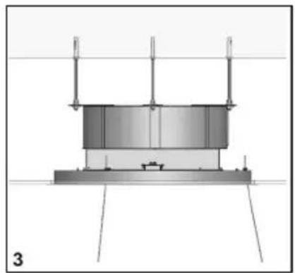
natural_image
Technical diagram of a cylindrical tank mounted on a platform, with support legs and no visible text or symbols.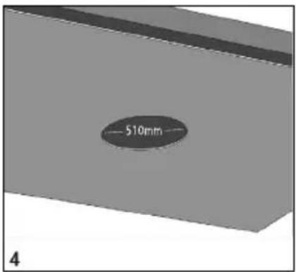
text_image
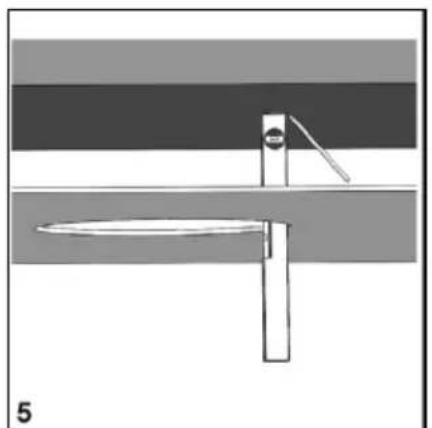
510mm 4Using a level and pencil, mark the four edges of the hole created in the plasterboard directly onto the solid ceiling, see fig. 5, then draw perpendicular lines as shown in fig. 6, to find the centre of the hole.
Position the drilling template supplied, aligning the centre of the template with the centre of the axes previously drawn (fig. 7). Using a pencil, trace the three holes to be made in the solid ceiling.
Before tracing the holes you can rotate the drilling template in order to orientate the air outlet of the fan to the desired direction. The position of the air outlet of the fan is indicated in the drilling template.
Drill three holes into the solid ceiling using a drill tip with a diameter of 8mm.
natural_image
Diagram of a mechanical or electrical component with layered bands and a central rod, no visible text or symbols
natural_image
Simple gray circular shape divided into four equal quadrants by a horizontal line (no text or symbols)
text_image
Drilling Template 7Place the metric inserts supplied into the holes.
Place the threaded bars into the metric inserts.
Screw the threaded bars using a metal washer and two nuts, as shown in fig. 8.
Insert an additional nut, a metal washer and a plastic locking washer as shown in figure 9. For correct installation, position the metal washer 200mm high from the bottom surface of the plasterboard, see figure 10.
Remove the product from its packaging and place it on a suitable surface: we suggest using a soft material, such as a cloth.
Open the panel as shown in Fig. 1 and described in the previous paragraph, remove the grease filter using the handle.

text_image
Metric Insert Threaded Bar 8
text_image
Additional Nut — Plastic Locking Washer Metal Washer 9
text_image
200mm 10Using a suitable tool, remove the eight screws securing the outer frame and then remove it as shown in Fig. 11.
Disconnect the flat cable and the electrical cable of the reset button.
Install the upper part of the product in the plasterboard niche. The three slots must coincide with the threaded rods previously installed, as shown in fig. 12.

natural_image
3D mechanical assembly diagram showing internal components with no visible text or symbols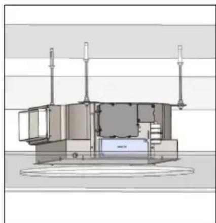
natural_image
Technical line drawing of a mechanical device with mounting flanges and internal components (no text or symbols)Bring the product to a stop with the washers previously positioned.
Secure the product with the washers and three nuts supplied. (fig.13)
Connect the air outlet duct and the power supply.
Remove the LED ceiling light from its packaging and run the cables through the three holes in the frame (fig.14).
Adjust the desired height of the LED ceiling light to the floor using the cable clamp as shown in fig.15.
Move the frame closer to the plasterboard niche, then restore the previously removed electrical connections and make the electrical connection of the LED ceiling light, taking care not to confuse the positive, negative and ground polarities indicated by the labels in the electrical cables.
Lock the product to the niche with the eight screws previously removed, fig.16.
Restore the grease filter and the metal panel fixed with special magnets.

natural_image
3D rendering of a mechanical assembly with a vertical rod and mounting bracket (no text or symbols visible)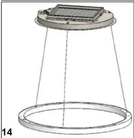
natural_image
Technical diagram of a conical device with a top platform and circular base, no visible text or symbols
natural_image
Diagram of a curved road with a small vehicle and a weight, no visible text or symbols
natural_image
3D diagram of a mechanical assembly with a central component and two concentric rings, no text or symbols presentREMOTE CONTROL
Radio control used for the remote operation of ducted cooker hoods.
TECHNICAL DATA
Alkaline battery powered: 12 V mod. 27A
Operating frequency: 433.92 Mhz
Combinations: 32.768
Max. Consumption: 25 mA
Operating temperature: -20 ÷ + 55 °C
Dimensions: 130x45x15 mm.

natural_image
Black rectangular electronic device with four small circular buttons and a central knob (no visible text or symbols)OPERATING DESCRIPTION
The transmitter is equipped with 5 buttons for cooker hood management, as specified below:

Light ON/OFF command

Motor ON (speed level 1) / OFF command

Reduce speed

Increase speed

10-minute timer
DIMMABLE LIGHTS FUNCTION
This function provides for light dimmability, ranging from 20% to 100%, by continuously pressing the light key on the remote control.
Functions are the following:
Hood light off - shortly press the key - light at 100%
Light on at 100% - shortly press the key - light off
Light on at 100% - continuously press the key - brightness reduction
Releasing the key during reduction or increase - light keeps the luminous intensity reached
Light on - dimmed - continuously press the key - brightness is inverted if compared to the previous function
The manufacturer supplies the radio control unit ready to be used with codes preset in the Factory.
STANDARD CONFIGURATION
Standard configuration requires all “cooker hoods – radio control - system” to be provided with the same transmission code. In the event two cooker hoods – radio control system are installed in the same room or nearby, each system may affect the operation of the another. Therefore, the code of one radio control system must be changed.
GENERATING A NEW TRANSMISSION CODE:
The radio control system is provided with preset codes. Should new codes be required, proceed as follows: Press simultaneously buttons: + ⏻ for two seconds. When LEDs light on, press buttons: + —(within 5 seconds). LEDs flashing 3 times indicate the procedure is completed.
WARNING :
This operation permanently deletes the preset codes.
LEARNING THE NEW TRANSMISSION CODE:
Once the transmission code is changed in the radio control unit, the electronic central unit of the cooker hood must be made to set the new code in the following way:
Press the main power-off button on the hood and then restore power to the electronic control unit. Within the next 15 seconds, press the light button ⚙️ to synchronise the central unit with the code.
RESET OF THE FACTORY CONFIGURATION:
To restore the Factory configuration, follow the procedure described below: simultaneously press buttons: + ⏻ — for 2 seconds. When Leds light on, press buttons: ⚙️ (within 5 seconds). LEDs flashing 6 times indicate the procedure is completed.
WARNING :
This operation permanently deletes the preset codes.
EMERGENCY BUTTON:
In the event that the radio control does not work, use the emergency button to switch the appliance off. After any necessary repairs have been performed, reset the emergency button.
WARNING:
The battery should be replaced every year to guarantee the optimal range of the transmitter.
To replace the exhausted battery, take the plastic lid off, remove the battery and replace it with a new one, observing the correct battery polarities.
Used batteries should be discarded in special collection bins.
WARNING:
Any adjustments or modifications which have not been expressly approved by the holder of the legal conformity certificate may invalidate the user's rights relating to the operation of the device.
The products are endowed with an electronic device which allows the automatic switching off after 4 hours working from the last operation.
TIMING
This product is equipped with intelligent electronics which include a timer device for speed controls when the air capacity exceeds 650m^3/h . Internal motor models, with maximum air capacity higher than 650m^3/h , are equipped with a timer device that automatically switches the speed from 4th to 3rd speed, after 6 minutes operation.
External motor models are equipped with remote motors that, as for internal motor versions, include a timer device that switches down the speed when it exceeds 650 m³/h.(See External Motors Instructions). Remote motors, whose air capacity exceeds 650m³/h at both 4th and 3rd speed, will have the following by default timer control functions: The speed is automatically switched from 4th to 2nd speed, after 6 minutes operation.
If the appliance is working at 3rd speed, it is automatically switched to 2nd speed, after 7 minutes operation. Operation speeds can also be changed during operation. The energy consumption of the appliance in standby mode is lower than 0.5W.
CLEANING AND MAINTENANCE
Careful maintenance ensures smooth operation and long-lasting performance.
Special care must be taken with the grease filter.
To access the filter, proceed as follows:
In the Chapter - OPENING THE PANEL.
Remove the grease filter using the special handle.
To replace the grease filter after cleaning, fulfil the same operation in reverse order.
To remove the carbon filter, if installed, follow the same steps as the grease filter.
The carbon filter is located immediately above the grease filter.
Warm water and neutral detergents are recommended to clean up the appliance, while abrasive products should be avoided.
If the power cord is damaged, a qualified person must replace it.
It is possible to open the grease filter cover panel pulling it as shown in fig. 1.
The panel is fixed with three magnets, there are two safety cables to be released to remove the panel from the product.
For proper operation, it is recommended to install the product at a maximum distance, from the floor level, of 2000 - 2100mm.
Caple Service
Fourth Way
Avonmouth
Bristol
BS11 8DW
t: 0117 938 7420
e: service@caple.co.uk
www.caple.co.uk