LF633K200MM - Sewing machine Union Special - Free user manual and instructions
Find the device manual for free LF633K200MM Union Special in PDF.

User questions about LF633K200MM Union Special
0 question about this device. Answer the ones you know or ask your own.
Ask a new question about this device
Download the instructions for your Sewing machine in PDF format for free! Find your manual LF633K200MM - Union Special and take your electronic device back in hand. On this page are published all the documents necessary for the use of your device. LF633K200MM by Union Special.
USER MANUAL LF633K200MM Union Special
Adjusting instructions and illustrated parts list

natural_image
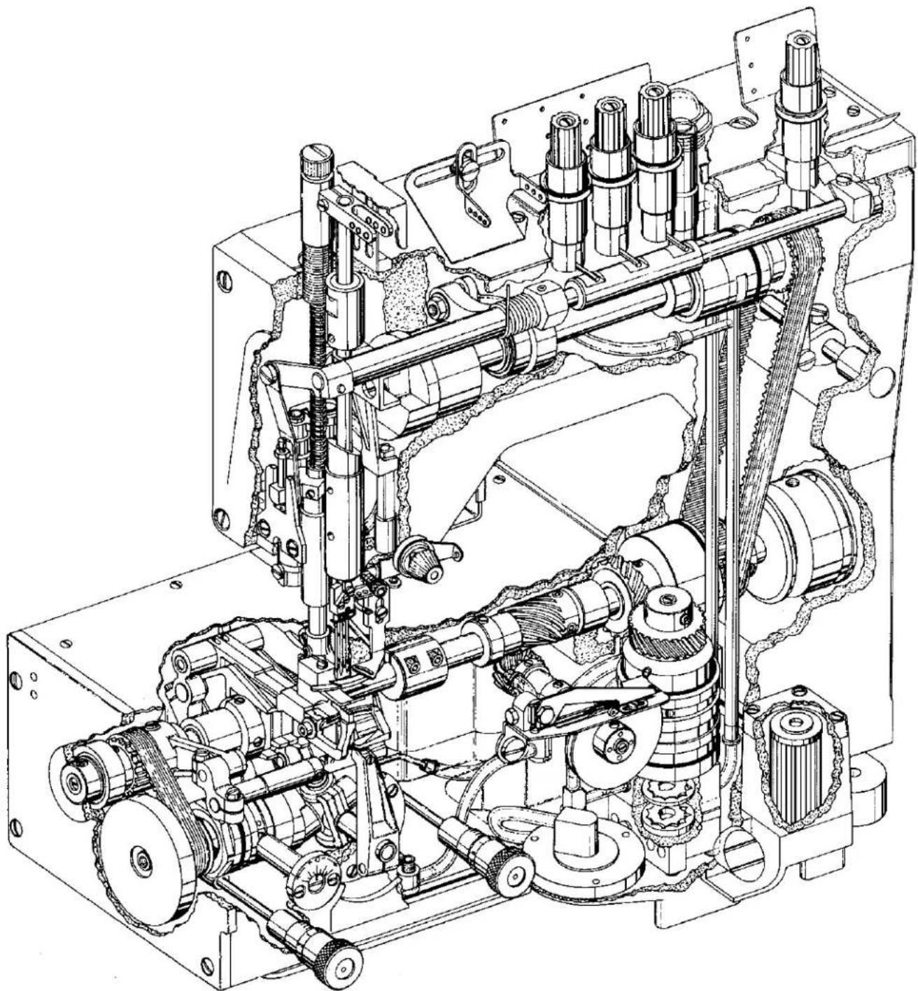
Historic black-and-white photograph of a vintage mechanical device labeled 'LITTLE 800' with no visible text or symbols beyond the label.Two- and three-needle, LF600 "Standard Class" differential feed, flatbed coverstitch machines.

text_image
U®Finest Quality
Union Special® Industrial Sewing Equipment
FOREWORD
This technical manual has been prepared to guide you in the maintenance of your new UNION SPECIAL machine. Careful attention to the instructions for operating and adjusting these machines will enable you to maintain the superior performance and reliability designed and built into every UNION SPECIAL machine.
The Adjusting Instruction portion of this manual explains in detail the proper setting for each of the components related to forming the stitch and completing the functions of the machine. Figures are used to illustrate the adjustments using reference letters to point out specific items discussed.
Adjustments are presented in sequence so that a logical progression is accomplished. Some adjustments performed out of sequence may have an adverse effect on the function of other related parts.
Implementation of Preventive Maintenance Schedule can bring about significant improvements in operator productivity by avoiding costly equipment breakdowns. Whenever it becomes necessary to make repairs or replace parts on your machine, be sure to insist on genuine UNION SPECIAL Repair Parts. These parts are designed specifically for your machine and manufactured with utmost precision to assure long lasting service.
This Catalog has been made on the basis of available information. Changes in design and/or improvements may incorporate a slight modification of configuration in illustrations or part numbers.
CATALOG NO. 143R
For Styles
LF632K200MV
LF633K200MN
LF633K200MM
LF633K200MW
First Edition
Copyright 1987
By
Union Special Corporation
Rights Reserved In All Countries
Printed in U.S.A.
Each UNION SPECIAL machine is identified by a Style number, which on this machine Class, is stamped into the Style plate affixed to the right front of the machine. The serial number is stamped into the bed casting at the left rear base of the machine.
NOTE: Instructions stating direction or location, such as right, left, front, or rear of machine, are given relative to the operator's position at the machine, unless otherwise noted. The handwheel rotates counterclockwise in operating direction, as viewed from the right end of the machine.
STYLES OF MACHINES
High speed, maximum performance, medium sewing capacity, two or three needle, one looper, spreader, differential feed flat bed machines. Totally enclosed feed and looper drive mechanism, fully automatic forced feed lubricating system with easily replaceable oil filter, thumbscrew adjustable main and differential feeds, independently driven rear needle guard and quick adjustable looper avoid.
LF632K200MV Two needle, four thread, offset differential feed machine for attaching collarettes to knitted undergarments, long length rib knit strip cut perpendicular to the wale or parallel with the wale. Stitch type 602. Standard gauge Nos. 8 and 12. Speeds up to 6000 R.P.M. Stitch range 9 to 16 S.P.I.
LF633K200MM Three needle, five thread, offset differential feed machine for attaching cuffs and crotch seaming operation to knit garments. Stitch type 605. Standard gauge No. 16. Speeds up to 6000 R.P.M. Stitch range 9 to 16 S.P.I.
LF633K200MN Same as Style LF633K200MM except fitted with tandem differential feed.
LF633K200MW Same as Style LF633K200MM except fitted with parts for using a folder to attach split tube borders to knitted undergarments. Stitch range 9 to 12 S.P.I.
SAFETY RULES

CAUTION!
THIS SYMBOL INDICATES YOUR PERSONAL SAFETY IS INVOLVED
TO PREVENT PERSONAL INJURY:
- All power sources to the machine MUST be TURNED OFF before threading, oiling, adjusting, or replacing parts.
- Wear safety glasses.
- All shields and guards MUST be in position before operating machine.
- DO NOT tamper with safety shields, guards, etc., while machine is in operation.
LUBRICATION
IMPORTANT: Machine must be in a leveled position.
Oil has been drained from main reservoir before shipment. Use a straight mineral oil with a Saybolt viscosity of 90 to 125 seconds at 100 degrees Fahrenheit. This is equivalent to UNION SPECIAL Specification No. 175. Remove oil filler cap (A, Fig. 1) and fill to the TOP line of oil level gauge (B). Replace oil filler cap.
CAUTION! On new machines, machines that have been out of service for an extended period of time OR machines that have been drained of oil and refilled .... RUN MACHINE SLOWLY at 300 R.P.M. for approximately five minutes while paying strict attention to the oil flow indicator which should rise in the oil filler cap (A) and remain steady while machine is running. This must be noted to ensure that oil flow indicator is functioning and oil is circulating. Check oil level while machine is running which MUST be maintained between the red lines of oil level gauge.
To maintain maximum recommended speed and serviceability of these machines, refer to General Preventive Maintenance Schedule. Under no circumstances, should oil remain in the machine for more than one year. Oil drain plug is located in bottom of oil pan. ALWAYS change oil filter when oil is changed. At this time, evaluate the contaminated condition of the oil to determine if the oil filter should be changed more or less frequently. To replace filter, remove four screws (C, Fig. 1) and cover (D); lift out filter cartridge. REMOVE (brass) BY-PASS VALVE FROM TOP OF OLD FILTER AND INSTALL IN NEW FILTER. Reassemble in reverse manner.
LUBRICATION DIAGRAM

text_image
Technical schematic diagram of a mechanical device with labeled components A, B, C, and D
PRESSURE OIL

SIPHON RETURN

INLET

FILTER BY-PASS
P100A
Fig. 1

text_image
PIVOT GUARD TO LEFT FOR THREADING A171A UNION SPECIAL UNION SPECIAL THREADING DIAGRAMNEEDLES
Each needle has both a type and size number. Type number denotes the kind of shank, point, length, groove, finish, and other details. Size number, stamped on the needle shank in metric, denotes largest diameter of blade, measured midway between shank and eye. Collectively, type and size number represent the complete symbol, which is given on the label of all needles packaged and sold by UNION SPECIAL CORPORATION.
Standard recommended needle for machines covered is Type 128 GBS, Size 75/029. Below is the description and sizes available:
NEEDLE TYPE
128 GBS
DESCRIPTION
Round shank, round point, short, double groove, struck groove, ball eye, spotted, ball point, chromium plated.
SIZE AVAILABLE
65/025, 70/027, 75/029, 80/032, 90/036, 100/040.
To have needle orders promptly and accurately filled, an empty package, a sample needle, or the type and size number should be forwarded. Use description on label. A complete order would read "1000 needles, Type 128 GBS, Size 75/029".
The following instructions explain in detail the proper setting for each of the components related to forming the stitch and completing the functions of the machine.
Adjustments are presented in sequence so that a logical progression is accomplished. Some adjustments performed out of sequence may have an adverse effect on the function of other related parts.
THREAD MACHINE AS ILLUSTRATED.

text_image
A134 A B B AFig. 2

text_image
A B A 102AFig. 3
text_image
.002" (.051mm) A 103 B E F D C AFig. 4
TIMING FEED TO NEEDLE
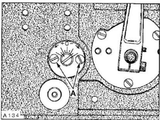
Adjustment would be required if the machine is feeding while the needles are in the work. This can be accomplished by removing top cover, head cover, left cloth plate, and top feed chamber cover. Rotate handwheel in operating direction to position needle bar at bottom of stroke. At this time, the first screws (A, Fig. 2) in the feed drive eccentricities (B) must be on the flat of the feed drive shaft and in a vertical position. Adjustment can be made by loosening two screws (A, Fig. 3) in upper mainshaft sprocket (B). Hold the handwheel firmly with needle bar at bottom of stroke and rotate pulley as required to position screws (A, Fig. 2) so they are vertical. Tighten screws (A, Fig. 3) securely.
SYNCHRONIZING LOOPER AND NEEDLE MOTIONS
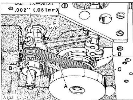
NOTE: End cover has been removed for clarity in Figure 4, but MUST BE IN POSITION WHILE MAKING THE FOLLOWING ADJUSTMENTS.
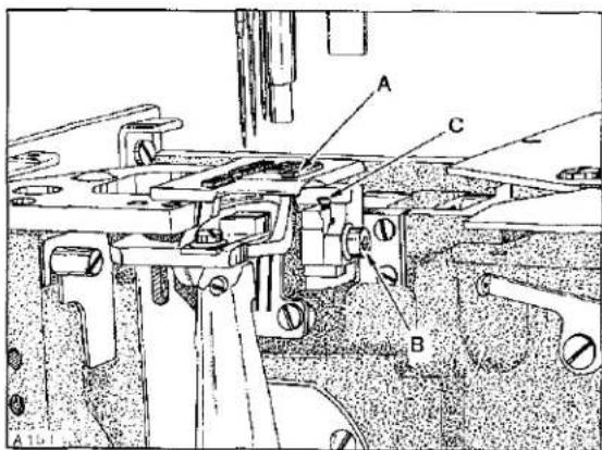
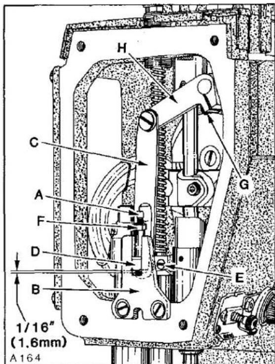
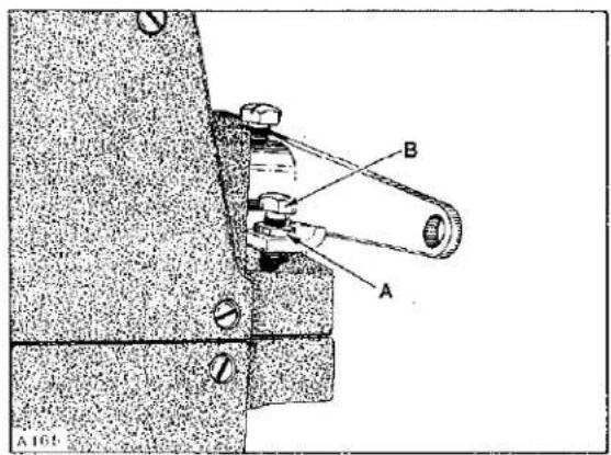
Looper drive belt (A, Fig. 4) has proper tension if, when turning handwheel in operating direction to position looper in the center of its (right to left) travel ... there is no noticeable (right to left) play in the looper mechanism. There should be approximately 1/8 inch (3.2mm) deflection in looper drive belt when pressing firmly with thumb, midway between sprockets (B and C). Adjustment can be made by loosening two screws (A, Fig. 5) and turn looper module (D, Fig. 4) counterclockwise to tighten belt or clockwise to loosen, as viewed in Figure 4. Retighten screws (A, Fig. 5).
To synchronize machine, remove needle bar eyelet guard, needle thread take-up wire holder, needles, presser foot, throat plate, looper, and feed dogs. Turn handwheel to position needle bar at BOTTOM of stroke and looper holder at EXTREME right end of travel.
SYCHRONIZING LOOPER AND NEEDLE MOTIONS (Continued)
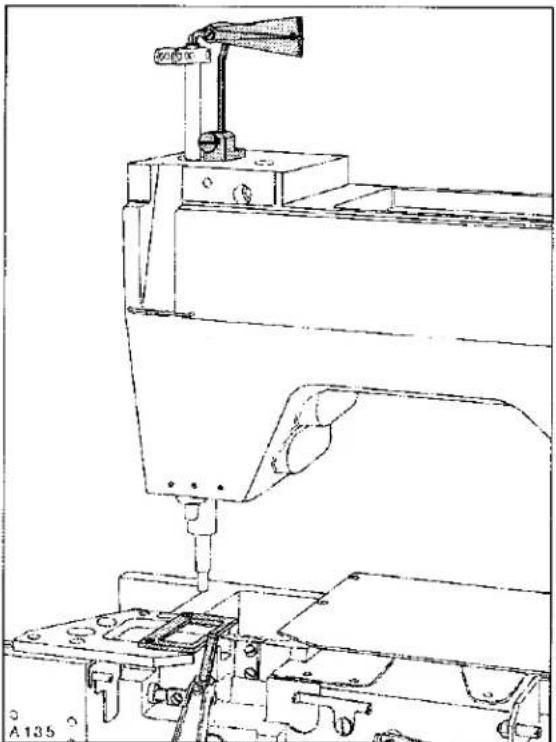
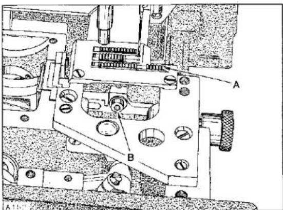
Using gauge No. 21227 R, mount gauge plate with throat plate attaching screws. Insert pin (included with gauge) into looper holder. Mount indicator block to machine head with one of the screws removed from needle bar eyelet guard. Insert shank of indicator gauge into indicator block and tighten screw against shank. See Sketch A for reference. Rotate handwheel in OPERATING direction until the pin in looper holder contacts gauge plate. Loosen screw (A, Fig. 6) in needle bar connection (B) and position needle bar (C) as required to set the pointer of indicator gauge at "0" and tighten screw (A) VERY LIGHTLY.
NOTE: This screw is specifically tightened to ONLY 10 - 12 in-lbs (12 - 14 cm/kg).
Rotate handwheel in REVERSE direction until pin in looper holder again makes contact with gauge plate and note the reading on the gauge. A variation of (1) graduation on the scale is permissible. If the reading is above "0", loosen screws (E, Fig. 4) and turn rear looper drive sprocket (B) towards the operator (clockwise as viewed in Figure 4). If the reading is below "0", turn sprocket away from operator (counterclockwise as viewed in Figure 4). Temporarily snug screws.
Rotate handwheel in OPERATING direction until pin in looper holder contacts gauge plate and note the reading on scale. If the reading is above "0", loosen screws (E) and turn sprocket (B) away from operator (counterclockwise as viewed in Figure 4). If the reading is below "0", turn sprocket towards the operator (clockwise as viewed in Figure 4). Temporarily snug screws.
Continue to check and adjust in both OPERATING and REVERSE directions until pointer of indicator gauge comes within (1) graduation on the scale when turning the handwheel in either direction. Before tightening screws (E) securely, be sure to have .002 inch (.051mm) clearance between sprocket (B) and needle guard drive connecting rod (F).
text_image
A A134Fig. 5
natural_image
Technical line drawing of a mechanical assembly with no visible text or symbolsSketch A

text_image
A1-6 B C AFig. 6
SYNCHRONIZING LOOPER AND NEEDLE MOTIONS (Continued)
text_image
LOOPER BEHIND NEEDLE LOOPER IN FRONT OF NEEDLE GREATEST LEAST OPERATING DIRECTION A107Sketch B
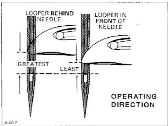
If a synchronizing gauge is not available ... turn the handwheel in operating direction to position looper point even with the left side of RIGHT needle and check the distance from the eye of needle to the bottom of looper blade. Turn handwheel in reverse direction to position looper point even with the left
side of RIGHT needle and check the distance from the eye of needle to the bottom of looper blade. If the distance was greater when handwheel was turned in operating direction, as shown in Sketch B, loosen screws (E, Fig. 4) and turn rear looper drive sprocket (B) away from operator
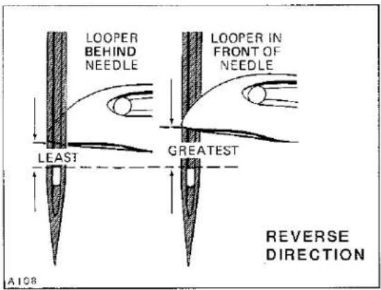
text_image
LOOPER BEHIND NEEDLE LEAST GREATEST LOOPER IN FRONT OF NEEDLE A108 REVERSE DIRECTIONSketch C
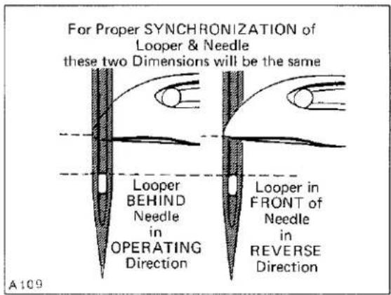
text_image
For Proper SYNCHRONIZATION of Looper & Needle these two Dimensions will be the same Looper BEHIND Needle in OPERATING Direction Looper in FRONT of Needle in REVERSE Direction A109Sketch D
(counterclockwise as viewed in Figure 4). If the distance was greater when handwheel was turned in reverse direction, as viewed in Sketch C, turn sprocket towards the operator (clockwise as shown in Figure 4). Temporarily snug screws. Continue to check and adjust in both OPERATING and REVERSE
directions until the distance from the eye of the right needle to the bottom of looper blade is the same in either direction, as shown in Sketch D. Before tightening screws (E, Fig. 4) securely, be sure to have .002 inch (.051mm) clearance between sprocket (B) and needle guard drive connecting rod (F).

text_image
Torque to 10-12 in-lbs (12-14 cm/kg) A 2" (50.8mm) A137A C BFig. 7
NEEDLE BAR ALIGNMENT
Insert a new set of needles. As a temporary setting, the TOP of needle bar (A, Fig. 7) should be approximately 2 inches (50.8mm) from the TOP of upper needle bar bushing when needle bar connection (B) is positioned at TOP of STROKE as shown in Figure 7. Adjustment can be made by loosening screw (C), reposition needle bar up or down as required and tighten screw (C) VERY LIGHTLY 10 - 12 in-lbs (12 - 14 cm/kg) maximum torque. Rotate handwheel to ensure that needles center in the needle holes of throat plate as shown in Figure 8. Adjustment can be made by loosening screw (C, Fig. 7) slightly, allowing needle bar to be rotated as required, while being careful to maintain the temporary height setting and tighten screw (C) AS SPECIFIED. An additional 4-way directional adjustment of the throat plate can be accomplished as follows:
IMPORTANT: Adjustment of throat plate must be coordinated between needles and feed dogs; refer to "FEED DOG SETTINGS". Loosen two screws (A, Fig. 8) in throat plate support (B). Loosen two screws (C) which secure locating ferrules, allowing the throat plate support to be repositioned slightly. Tighten screws (C) first, then screws (A).
CAUTION! Needle bar has a special coating. DO NOT wedge or pry with any type of tool, as damage to same may result. Should needle head require assembling to needle bar, TORQUE 14 - 16 in-lbs (16 - 18 cm/kg).
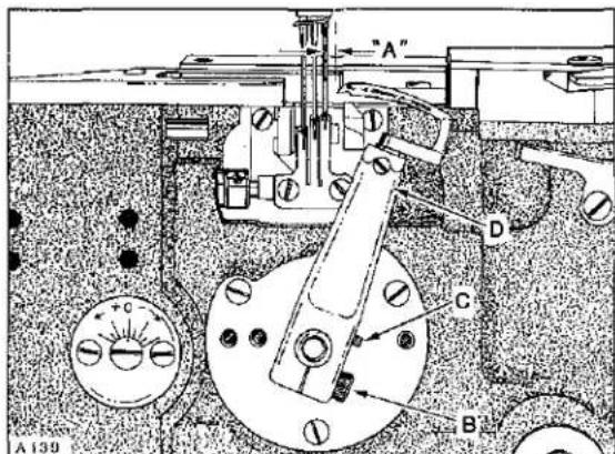
LOOPER SETTINGS
If not previously done, insert a new set of needles. With looper at EXTREME right end of travel, distance from centerline of RIGHT needle to point of looper should be dimension ("A", Fig. 9); see CHART. Adjustment can be made by loosening screw (B) and turn screw (C) clockwise to increase looper gauge or counterclockwise to decrease. Apply pressure against upper portion of looper holder (D) to the left while making this adjustment and locking with screw (B). Applicable looper gauge can be used advantageously in making this adjustment. Looper must also be set so, as it travels to the left behind the needles, NOT to contact, but with a clearance of .002 - .004 inch (.051 - .102mm).

text_image
A B C A 138Fig. 8
text_image
"A" D C B A139Fig. 9
text_image
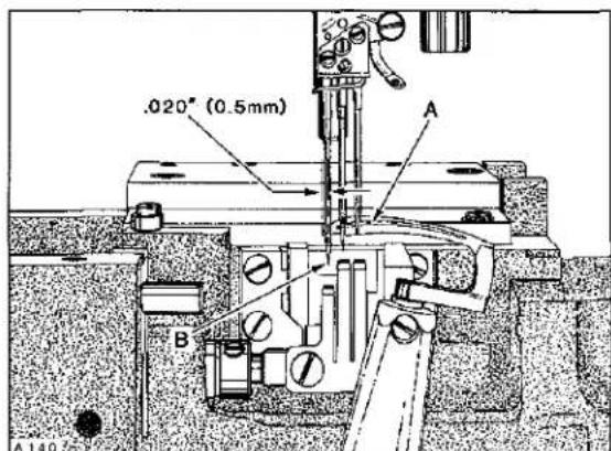
.020" (0.5mm) A B A 140Fig. 10
LOOPER SETTINGS (Continued)
Adjustment can be made by loosening screw (B) allowing looper holder (D) to be moved forward or rearward on its shaft, as required. Apply pressure against upper portion of looper holder to the left while tightening screw (B).
MACHINE STYLE
| LF632K200MV-8 |
| LF632K200MV-12 |
| LF633K200MM-16 |
| LF633K200MN-16 |
| LF633K200MW-16 |
DIMENSION "A" FIG. 9
| 5/32 inch (4.0mm) |
| 9/64 inch (3.6mm) |
| 1/8 inch (3.2mm) |
| 1/8 inch (3.2mm) |
| 1/8 inch (3.2mm) |
LOOPER GAUGE NO.
| 21225-5/32 |
| 21225-9/64 |
| 21225-1/8 |
| 21225-1/8 |
| 21225-1/8 |

text_image
A B A Torque to 10-12 in-lbs (12-14 cm/kg)Fig. 11
NEEDLE BAR HEIGHT
Needle bar height is set correctly when the point of looper (A, Fig. 10) moving from right to left, is .020 inch (0.5mm) to the LEFT side of the LEFT needle (B) with its underside even with the TOP of needle eye. Adjustment can be made by loosening screw (A, Fig. 11) and move needle bar (B) up or down as required. TORQUE screw (A) to 10 - 12 in-lbs (11.5 - 14 cm/kg).
IMPORTANT: Care must be taken not to disturb ALIGNMENT of needle bar while making this adjustment.
CAUTION! Needle bar has a special coating. DO NOT wedge or pry with any type of tool, as damage to same may result.

text_image
B A A14 Left Needle Upper Edge of Looper 2/3 1/3Fig. 12
LOOPER AVOID
Machine is equipped with a quick adjustable looper avoid mechanism to accommodate extreme differences in needle sizes. As the looper travels from left to right with the needle bar descending, the LEFT needle should contact ONLY the lower THIRD of the back of looper blade. Adjustment can be made by loosening two screws (A, Fig. 12) and turn eccentric stud (B) towards the plus side (counterclockwise) for MORE looper avoid or towards the minus side (clockwise) for LESS. When properly set, tighten screws (A).
NOTE: Whenever looper avoid is changed, always recheck "LOOPER SETTINGS".
REAR NEEDLE GUARD TIMING AND ADJUSTMENT
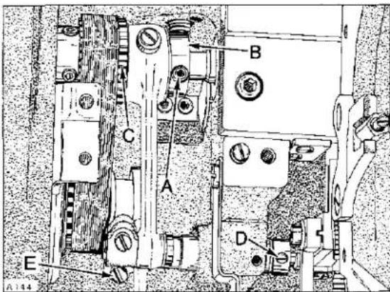
As the looper travels from right to left, position looper point midway between the right and center needles as shown at ("A", Fig. 13) for 16 GAUGE machines. For 8 and 12 GAUGE machines, position looper point even with the right side of right needle. At this time the rear needle guard (B) should be at EXTREME end of forward travel.
Adjustment can be made by loosening two screws (A, Fig. 14) and rotate needle guard eccentric (B) slightly as required until this condition exists. Check to ensure .002 inch (.051mm) clearance between needle guard eccentric (B) and looper drive sprocket (C) while tightening screws (A) securely.
Needle guard should be positioned (left to right) so the needles center in the width of their guarding surfaces.
Adjust by loosening collar screw (D) and pivot link screw (E) permitting guarding surface to be centered to needles. Position collar against needle guard shaft bushing and tighten screw (D) securely. Rotate guard as required to obtain .002 inch (.051mm) clearance between guarding surface and needles. Take up thrust by exerting pressure against collar to the left and pivot link to the right while tightening pivot link screw (E) securely.
As the looper travels from right to left, position its point even with the right side of right needle. At this time, the height of needle guard (A, Fig. 15) should be positioned so the lower edge of its guarding surface (B) is even with the TIP of RIGHT needle (C).
Adjust by loosening two screws (D), reposition as required, being CAREFUL to keep the width of guarding surfaces CENTERED to needles while tightening screws (D).
NOTE: Needle guards can be bent slightly (individually) front to back, if required.
IMPORTANT: Change in stitch length WILL NOT require change in needle guard setting, but a change of needle SIZE, may.

text_image
"A" B A 143Fig. 13
text_image
A.144 B C A D EFig. 14

text_image
A 145 B C D A DFig. 15
text_image
A C D B A146Fig. 16
FRONT NEEDLE GUARD
Front needle guard (A, Fig. 16) is magnetized and must be positioned vertically to provide ample clearance on all sides of the INNER CONTOUR of looper when looper is at extreme left and right end of travel. With looper even with the right side of RIGHT needle, needle guard should be set to barely contact the needles.
Adjustments can be made by loosening two screws (B) to reposition bracket (C) as required....retighten screws. Loosen screw (D) allowing needle guard (A) to be moved towards or away from needles as required....retighten screw.
FEED DOG SETTINGS

text_image
A 147 B C A C AFig. 17
Feed dogs should be centered in throat plate with equal clearance on both sides and ends. Feed dogs should be level with and parallel to the top of throat plate as they begin to rise. Feed dogs should be set to protrude the depth of a full tooth or approximately 3/64 inch (1.2mm) above throat plate, at highest point of travel.
A slight 4-way directional adjustment of the throat plate can be accomplished by loosening two screws (A, Fig. 17) in throat plate support (B). Loosen two screws (C) which secure locating ferrules, permitting movement of throat plate support. Reposition as required, considering BOTH the needle holes and feed dog slots in throat plate. Tighten screws (C) FIRST, then screws (A). Under EXTREME conditions, a very slight (right to left) adjustment of feed dogs can be acquired by loosening their respective feed dog holder screws....RETIGHTEN.

text_image
A B A 14KFig. 18
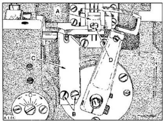
Should (front to rear) adjustment be required, remove the rear feed chamber cover which is secured by four screws. Turn the main feed (stitch regulating) knob (A, Fig. 18) counterclockwise while simultaneously ROTATING HANDWHEEL IN OPERATING DIRECTION to obtain maximum travel. NOTE: Collar (A, Fig. 19) may have to be loosened at the rear of bed casting on the main feed stitch regulating shaft. Centralize movement of main feed dog by loosening Allen screw (A, Fig. 20) and turn eccentric (B) as required.
FEED DOG SETTINGS (Continued)
Coordinate these adjustments to obtain maximum travel and equal clearance at both ends of throat plate. Tighten Allen screw (A) TEMPORARILY.
Loosen screw (C, Fig. 20) and rotate feed rocker tilting shaft (B, Fig. 19) slightly as required while ROTATING HANDWHEEL IN OPERATING DIRECTION to attain maximum forward travel of feed dogs, yet FLUSH with the top of throat plate as they first appear. COORDINATE this adjustment with those described in preceding paragraph. Apply a slight pressure against feed rocker tilting shaft (B) to ensure no BIND or SHAKE at the rear ENDS of feed bars while tightening screw (C, Fig. 20) securely. Tighten Allen screw (A) securely and collar (A, Fig. 19) on the main feed stitch regulating shaft against the bed casting. Turn main feed regulator knob (A, Fig. 18) clockwise for shortest stitch length.
Adjust differential feed dog (front to rear) in the same manner as main feed dog by loosening collar (C, Fig. 19) and turning differential feed knob (B, Fig. 18). Loosening Allen screw (D, Fig. 20) and turning eccentric (E).
NOTE: Adjustment of differential feed dog should not require resetting of feed rocker tilting shaft (B, Fig. 19).
CAUTION! While adjusting for maximum and centralized feed travel, continually check clearance between main feed dog and throat plate.
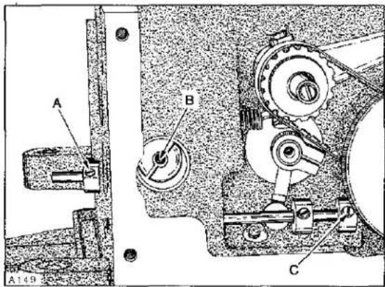
Tighten (stop) collar (C, Fig. 19) against bed casting and tighten Allen screw (D, Fig. 20) securely. With feed travel set to desired stitch length, set height of main feed dog (A, Fig. 21) as specified by loosening its mounting screw (B) to position as required. Feed dog supporting screw (C), located in feed dog holder should be adjusted as required to support feed dog before tightening screw (B) securely. Height of differential feed dog (A, Fig. 22) can be set by loosening its mounting screw (B) to position as required. Tighten screw (B) securely.
text_image
A B C A149Fig. 19
text_image
A B E D CFig. 20
text_image
Technical diagram of a mechanical assembly with labeled parts A, B, and CFig. 21
natural_image
Technical line drawing of a mechanical assembly with labeled parts A and B (no readable text or symbols)Fig. 22
CHANGING STITCH LENGTH
Stitch length is controlled by the distance main feed travels with its teeth protruding above the throat plate, which can be changed by turning stitch regulating knob (A, Fig. 18) clockwise to shorten the stitch or counterclockwise to lengthen same.
Differential feed travel is controlled independently from main feed travel by turning differential ratio feed knob (B, Fig. 18) clockwise to gather or counterclockwise to stretch the material between feed dogs.
NOTE: Adjustments were performed under "FEED DOG SETTINGS".

text_image
9/32" (7.1mm) A A153Fig. 23
SPREADER AND RELATED PARTS
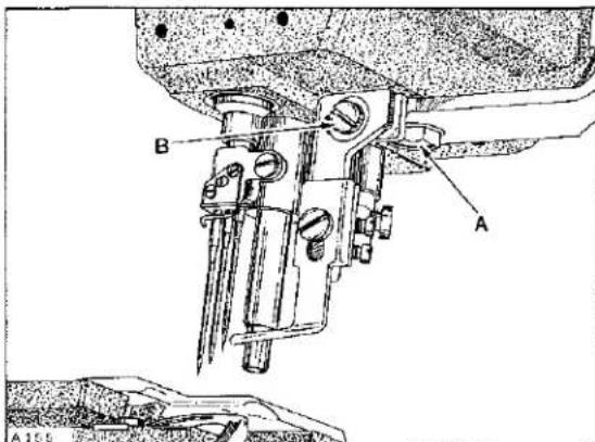
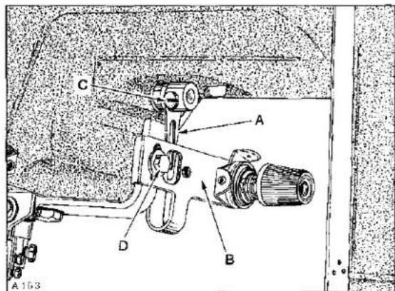
Stationary spreader thread guide (A, Fig. 23) should be positioned with its outer front edge 9/32 inch (7.1mm) to the front of the centerline of right needle. The left rear edge of the (banana shaped) SLOT in guide (A), should be positioned 1/16 inch (1.6mm) to the right of the centerline of right needle, as shown in Figure 24. Front to rear adjustment can be made by loosening screw (A, Fig. 25) while left to right adjustment can be made by loosening screw (B). When stationary spreader thread guide is properly set, tighten screws (A and B) securely.

text_image
1/16° (1.6mm) A A154Fig. 24
text_image
A B A 15.5Fig. 25
SPREADER AND RELATED PARTS (Continued)
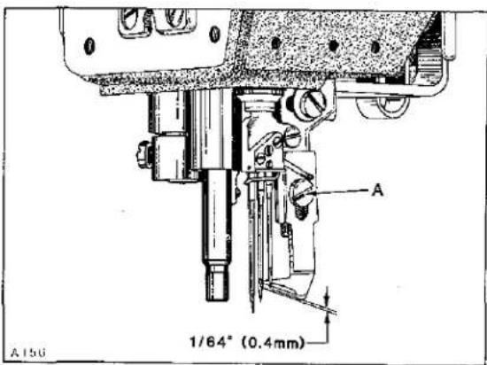
With needle bar at TOP of stroke, height of stationary spreader thread guide should be positioned with its UNDERSIDE PORTION (laterally in line with needles) 1/64 inch (0.4mm) below the TIP OF RIGHT needle as shown in Figure 26. Adjustment can be made by loosening screw (A), reposition as required...
text_image
A 1/64° (0.4mm) A 150Fig. 26
IMPORTANT: Care must be taken to maintain the 1/16 inch (1.6mm) dimension between the left rear edge of SLOT in stationary spread thread guide to centerline of right needle, while tightening screw (A) securely.
Spreader (A, Fig. 27) should be positioned so its upper surface clears the lowest edge of stationary guide (B) by .020 inch (0.5mm) and the rear side of spreader blade should clear the shank of left needle by 1/64 to 1/32 inch (0.4 to 0.8mm) throughout its arc of travel. Adjustment can be made by loosening screws (C), reposition as required and retighten screws securely.

text_image
.020 inch (0.5mm) A B C A157Fig. 27
While rotating handwheel in operating direction, spreader should be TIMED so it begins to move from extreme left position to the right as needle bar descends 1/16 inch (1.6mm) from TOP of stroke. Adjustment can be made by removing top cover, loosen two screws (A, Fig. 28) in hub of spreader drive eccentric (B), advance or retard eccentric on shaft (C) as required. When proper timing is obtained, position eccentric on its shaft (left to right) so as to ensure that spreader connecting rod (D) has MAXIMUM and CENTRALIZED SHAKE (left to right) while tightening screws (A) securely.

text_image
A158Fig. 28
text_image
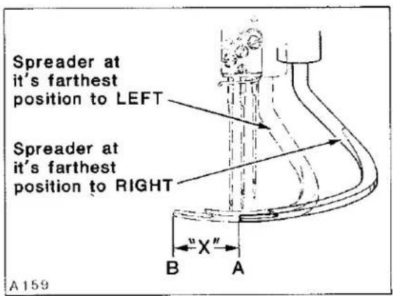
Spreader at it's farthest position to LEFT Spreader at it's farthest position to RIGHT A 159 B X"Fig. 29
SPREADER AND RELATED PARTS (Continued)
Spreader travel ("X", Fig. 29) is measured by placing a scale between the two extreme spreader arc travel points (not considering the arc), as shown between points (A and B). See chart for specified dimensions. Adjustment can be made by loosening nut (E, Fig. 28), move connecting rod (D) upward to shorten spreader travel or downward to lengthen spreader travel. After specified length of travel is obtained, tighten nut (E) securely.
text_image
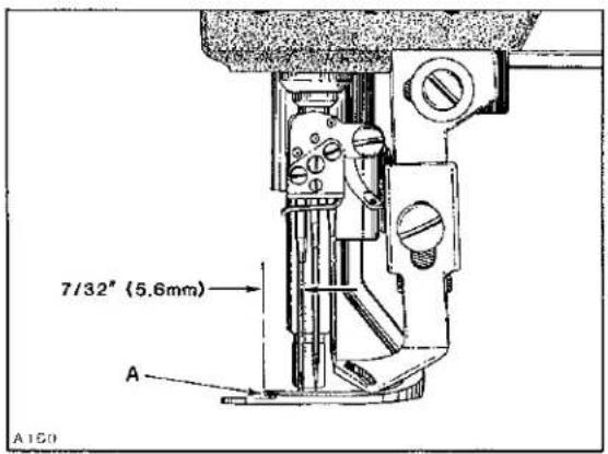
7/32" (5.6mm) A A150Fig. 30
| MACHINE STYLES | SPREADER TRAVEL "X" |
| LF632K200MV-8 | 33/64 inch (13.1mm) |
| LF632K200MV-12 | 37/64 inch (14.7mm) |
| LF633K200MM-16 | 5/8 inch (15.9mm) |
| LF633K200MN-16 | 5/8 inch (15.9mm) |
| LF633K200MW-16 | 5/8 inch (15.9mm) |
text_image
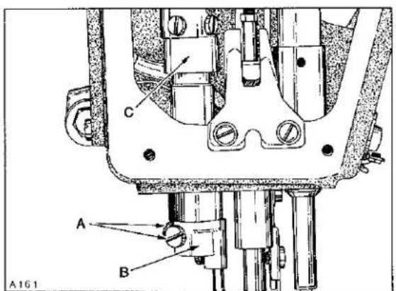
A B C A161Fig. 31
With spreader at extreme LEFT end of travel the TIP of thread carrying notch (A, Fig. 30) should be 7/32 inch (5.6mm) to the left of the centerline of LEFT needle. Adjustment can be made by loosening two screws (A, Fig. 31) allowing spreader holder (B) to be rotated on its shaft to attain dimension shown in Figure 30.
IMPORTANT: Take up thrust between spreader holder shaft lever (C, Fig. 31) and spreader holder (B) while tightening screws (A) securely. Recheck spreader height.
SPREADER AND RELATED PARTS (Continued)
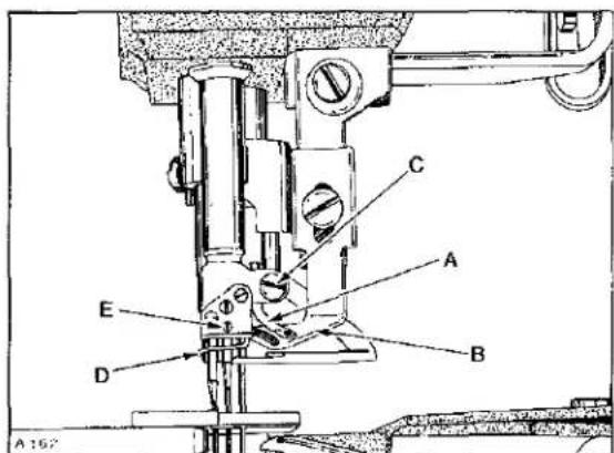
With needle bar at BOTTOM of stroke, spreader thread eyelet (A, Fig. 32) should clear stationary spreader thread guide (B) by approximately 1/32 inch (0.8mm) and aligned as close as possible with the center of the SLOT in same. If adjustment is required, care must be taken NOT to disturb alignment of needle bar. Loosening screw (C) which allows a 4-way directional movement of eyelet (A). Retighten screw (C).
Needle thread guide wire (D) should be centered around the needles and as close as possible to same without pinching the threads. Adjustment can be made by loosening screw (E), reposition as required and retighten screw.
Spreader thread take-up (A, Fig. 33) should be centered (left to right) between eyelet inserts in tension bracket (B). It should also be positioned to travel approximately equal distance (front to rear) of eyelets. Adjustment can be made by loosening screw (C), reposition take-up (A) as required and retighten screw (C) securely.
More or less thread can be supplied in the system by loosening screw (D) and move bracket (B) downward for more thread or upward for less thread. Retighten screw (D) securely.
PRESSER BAR AND PRESSER FOOT
With needle bar at bottom of stroke and presser foot resting squarely on throat plate, there should be a minimum clearance of 1/64 inch (0.4mm) between the bottom of screw (A, Fig. 34) and bottom of slot in presser bar guide plate (B). At this time, there should be at LEAST 1/32 inch (0.8mm) clearance between bottom of presser bar guide and top of lower presser bar bushing. There should also be 1/16 inch (1.6mm) clearance between bottom of slot in lifter lever link (C) and bottom of presser bar guide (D) when foot lifter lever is released. If adjustment is required, proceed as follows:
text_image
A 162 C A B D EFig. 32
text_image
A 163 C A D BFig. 33
text_image
H C A F D B 1/16" (1.6mm) A164 G EFig. 34
PRESSER BAR AND PRESSER FOOT (Continued)
text_image
A B A 164Fig. 35
Back off presser bar spring regulator to release tension on spring. Loosen two screws (E) in presser bar guide (D). Loosen nut (F) and turn screw (A) down against guide plate (B) to obtain at least 5/64 inch (2.0mm) clearance between bottom of presser bar guide (D) and guide plate (B). Align presser foot with needles and press down FIRMLY while tightening two screws (E) in presser bar guide (D).
NOTE: This setting was necessary to prevent damage to the scraper edge of presser bar bushing, should presser foot be removed from machine. Turn presser bar spring regulator down. Back off screw (A) to obtain the 1/64 inch (0.4mm) dimension between bottom of screw and bottom of slot in presser bar guide plate (B), lock nut (F).

text_image
Clearance with foot at highest position A160Fig. 36
Loosen screw (G) in lifter arm (H) and rotate arm slightly as required to obtain the 1/16 inch (1.6mm) dimension between link (C) and guide (D), retighten screw (G) ensuring no left to right shake in lifter arm (H).
Loosen lock nut (A, Fig. 35) and adjust screw (B) in presser foot lifter lever, allowing presser foot to be raised to its highest position without interfering with spreader, as shown in Figure 36. Lock nut (A, Fig. 35) securely.
Adjust presser bar spring regulator so it exerts only enough pressure on presser foot to feed the work uniformly. Turning it clockwise increases the pressure, counterclockwise acts the reverse.
LOOPER THREAD TAKE-UP AND CAST-OFF PLATE
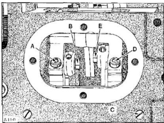
Looper thread take-up (A, Fig. 37) should be centered front to back in cast-off plate (B). It should also be positioned so as the needle bar is descending, looper thread is "cast-off" the highest lobe of looper thread take-up when the tip of left needle is even with the bottom of looper blade.
If adjustment is required, lift cast-off plate up. Loosen screw (A, Fig. 38) in positioning collar (B) and two screws (C) in looper thread take-up. Advance or retard looper thread take-up as required and tighten screws (C) assuring that take-up is centered in cast-off plate. Positioning collar (B), which has a slot in its face, must be aligned with two screws which secure the discs of take-up together while THRUSTING positioning collar forward against take-up. Remove the play between screw heads in take-up and slot in positioning collar by applying pressure on the collar CLOCKWISE while tightening screws (A) securely. Cast-off plate (B, Fig. 37) should be positioned with .004 inch (0.1mm) clearance between cutting edge of looper thread anti-wrap-up knife (C) and hub (D) of looper thread take-up, which can be adjusted by repositioning latch (D, Fig. 38). Set adjustable eyelets (E, Fig. 37) in the center of their mounting screws. More or less looper thread can be supplied in the stitch by moving adjustable eyelets to the right or left respectively.

text_image
A107 B C D E F G H J KFig. 37
If retaining finger is rubbing take-up, loosen screw (F), center the finger (G), and retighten screw. If retaining finger is on an angle, loosen screw (H), turn retaining finger support (J) slightly as required and retighten screw. The height of retaining finger should be set with its right end resting squarely on top of cast-off plate and the inner contour of the left end should be 1/32 inch (0.8mm) above the HIGHEST lobe of looper thread take-up. Loosen screw (K), position as required and retighten screw.
THREAD TENSION RELEASE
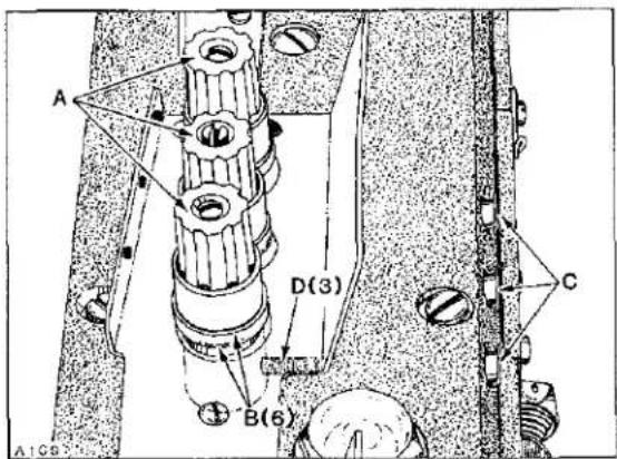
Needle thread tension assemblies (A, Fig. 39) are set correctly when the tension discs (B) start to release as the presser foot is raised to within 1/8 inch (3.2mm) of the end of its travel and completely released when presser foot has reached its highest position.

text_image
A B C D A 168Fig. 38
text_image
A D(3) B(6) C A1G8Fig. 39
THREAD TENSION RELEASE (Continued)
Adjustment can be made by removing plastic plugs (C), and loosening screws (D) and lower tension assemblies (A) to advance the release action or raise tension assemblies to retard the release action. Hold tension assemblies in position while retightening screws (D). Reassemble plastic plugs securely.
THREAD CONTROL (PRELIMINARY SETTINGS)
As a factory setting, needle thread take-up wires are positioned so their ends are flush with the rear side of holder, though under extreme conditions, they may be adjusted independently as required to suit.

text_image
B C A A1/DFig. 40
Needle bar eyelet should be positioned on the needle bar to CENTRALIZE its up and down travel between the extreme ends of take-up wires with equal clearance on both sides of same.
With needle bar at TOP of stroke, needle thread take-up wire holder (A, Fig. 40) should be positioned (front to rear) with 1/16 inch (1.6mm) clearance between front surface of front take-up wire and centerline of front eye in needle bar eyelet (B). If adjustment was required, be sure to center take-up wires between eyes of needle bar eyelet.
Adjustment of parts mentioned can be accomplished by loosening their mounting screws, reposition as required and retighten screws.
CAUTION! TORQUE needle bar eyelet screw to ONLY 10 - 12 in-lbs (12 - 14 cm/kg).
As a starting point the needle thread (adjustable) eyelet (C) should be set 1 13/32 inch (35.7mm) from its left side to the right side of needle bar eyelet (B) and 1 3/8 inch (34.9mm) from the center line of its eyelet holes to the top of top cover.
Tension on needle thread should be just enough to pull up uniform stitches. Tension on looper thread should be just enough to steady thread.
natural_image
Technical line drawing of a mechanical assembly with gears, shafts, and housing (no text or labels)EXPLODED VIEWS
AND
DESCRIPTION OF PARTS
P129
text_image
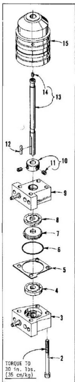
TORQUE TO 30 in. lbs. (35 cm/kg)→1
text_image
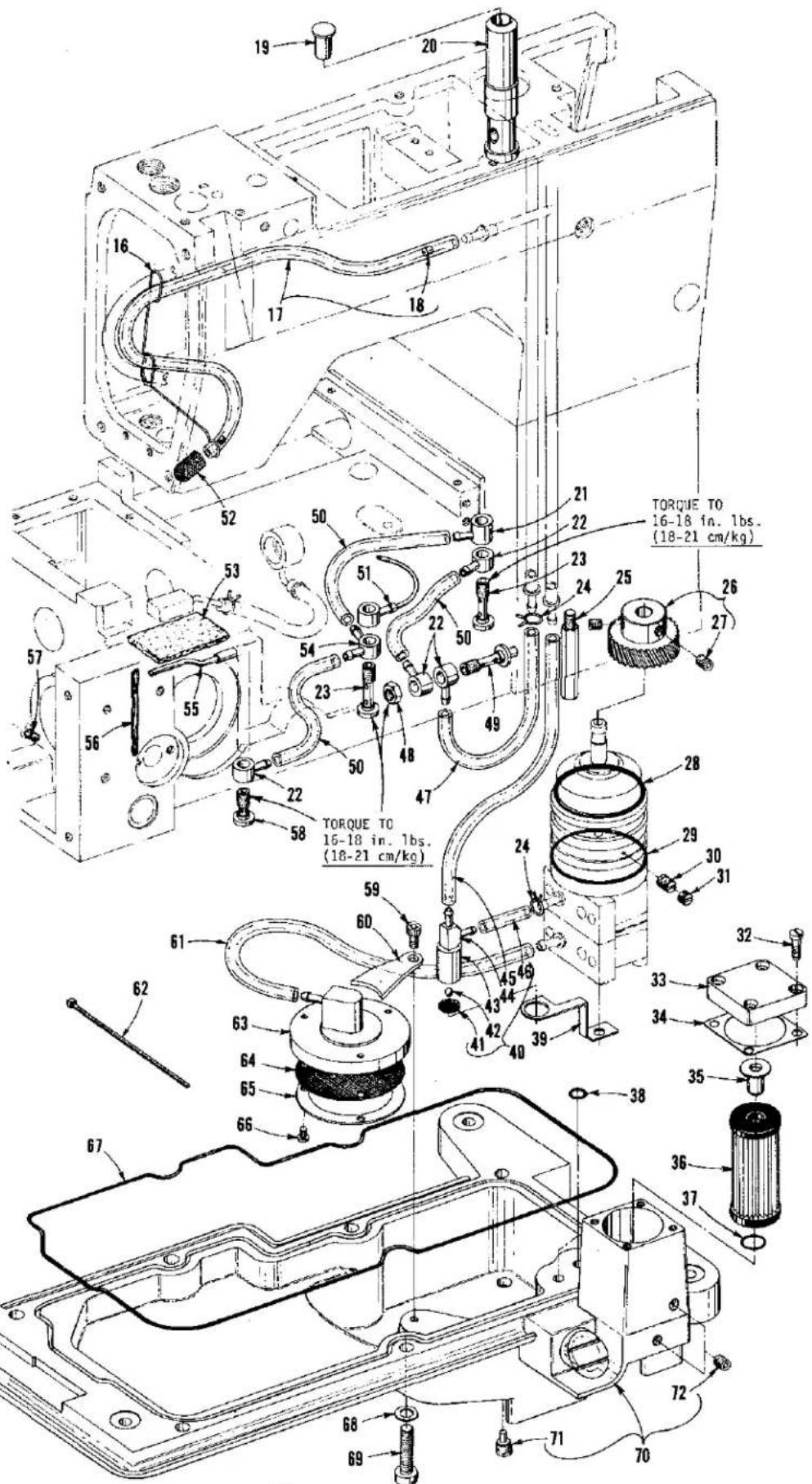
19 20 16 17 18 52 50 51 21 22 TORQUE TO 16-18 in. 1bs. (18-21 cm/kg) 53 23 24 25 26 57 56 54 50 48 49 27 58 TORQUE TO 16-18 in. 1bs. (18-21 cm/kg) 22 59 60 24 28 29 30 31 61 62 63 64 65 66 45 49 43 44 41 40 39 32 33 34 35 36 37 67 68 69 70 71 72OIL PUMP, PAN, AND LUBRICATING PARTS
| Ref.No. | PartNo. | Description | Amt.Req. |
| 1 | 50393 E | Pump Assembly, oil | 1 |
| 2 | 22653 B-36 | Screw | 4 |
| 3 | 50393 F | Housing, (pressure side) | 1 |
| 4 | C50093 U | Gerotor, 1/4 inch (6.4mm) thick | 1 |
| 5 | C50093 T | Divider, housing | 1 |
| 6 | 660-684 | "0" Ring | 1 |
| 7 | C50093 S | Spacer, housing | 1 |
| 8 | C50093 R | Gerotor, 1/8 inch (3.2mm) thick | 1 |
| 9 | 50393 J | Housing, (syphon side) | 1 |
| 10 | 35036 X | Collar, (positioning and thrust) | 1 |
| 11 | 22894 C | Screw | 2 |
| 12 | C50093 Z | Pin, dowel | 1 |
| 13 | 50393 D | Shaft, drive | 1 |
| 14 | 89 | Screw | 1 |
| 15 | 50393 C | Bushing, oil delivery | 1 |
| 16 | 50393 V | Retainer, wire | 1 |
| 17 | 50393 AX | Tube, oil return | 1 |
| 18 | 50393 BB | Restrictor, oil | 2 |
| 19 | 50393 AT | Cap, oil indicator | 1 |
| 20 | 50393 A | Indicator, oil, (priority metering valve) | 1 |
| 21 | 50394 K | Connector, oil, single feed | 1 |
| 22 | C50094 C | Connector, oil, single feed | 4 |
| 23 | 35094 A | Screw, oil connection | 2 |
| 24 | 668-885 | Clamp, oil tube | 2 |
| 25 | 22841 M | Stand, oil plug | 1 |
| 26 | 35039 A | Gear, driven, oil pump | 1 |
| 27 | 22894 J | Screw | 2 |
| 28 | 661-51 | "0" Ring, | 1 |
| 29 | 660-455 | "0" Ring, | 1 |
| 30 | 74 E | Screw | 1 |
| 31 | 22586 | Screw, Locking | 1 |
| 32 | 22541 | Screw | 4 |
| 33 | C50093 F | Cover, oil filter | 1 |
| 34 | C50093 G | Gasket | 1 |
| 35 | C50093 CB | By-Pass, oil filter | 1 |
| 36 | C50093 CA | Filter, oil | 1 |
| 37 | 660-206 | "0" Ring | 1 |
| 38 | 999-211 E | "0" Ring | 2 |
| 39 | 50393 BA | Bracket, manifold | 1 |
| 40 | 50393 AW | Syphon Assembly, oil | 1 |
| 41 | 50393 AU | Screen, oil | 1 |
| 42 | 79-31 | Ball, steel | 1 |
| 43 | 50393 AV | Manifold, oil syphon | 1 |
| 44 | 671 F-41 | Fitting | 1 |
| 45 | C50093 CJ | Tube, oil return | 1 |
| 46 | 50393 AY | Tube, oil | 1 |
| 47 | C50094 R | Tube, oil | 1 |
| 48 | 258 | Nut | 1 |
| 49 | 50393 BK | Fitting, oil | 1 |
| 50 | 50394 B | Tube, oil | 3 |
| 51 | 50394 L | Tube, oil, complete (take-up gear) | 1 |
| 52 | 50393 X | Screen, filter | 1 |
| 53 | 666-310 | Felt, oil return | 1 |
| 54 | C50094 B | Connector, double feed | 1 |
| 55 | 50394 G | Tube, oil (looper rocker) | 1 |
| 56 | WO-3 | Yarn, Columbia, rear needle guard bushing (8 strands) | 1 |
| 57 | C50094 AK | Plug, felt, oil return | 1 |
| 58 | 22720 A | Screw, oil connection | 1 |
| 59 | 22652 A-4 | Screw | 1 |
| 60 | 50393 AR | Clamp, oil screen housing | 1 |
| 61 | C50094 Y | Tube, oil | 1 |
| 62 | 670 E-2 | Tie, cable, to secure Ref. No. 45 to Ref. No. 22 | 1 |
| 63 | 35093 F | Housing, screen | 1 |
| 64 | 35093 H | Screen | 1 |
| 65 | 35093 J | Plate, retaining | 1 |
| 66 | 97 | Screw | 3 |
| 67 | 35082 B | Gasket, oil pan | 1 |
| 68 | 6042 A | Washer | 7 |
| 69 | 820 | Screw | 7 |
| 70 | 50393 | Pan, oil | 1 |
| 71 | 22571 E | Screw, oil drain plug | 1 |
| 72 | 22571 J | Screw, plug | 2 |
* 12-19-88 50393 AJ Replaces 50393 N 50393 BJ WILL Replace 50393 AJ
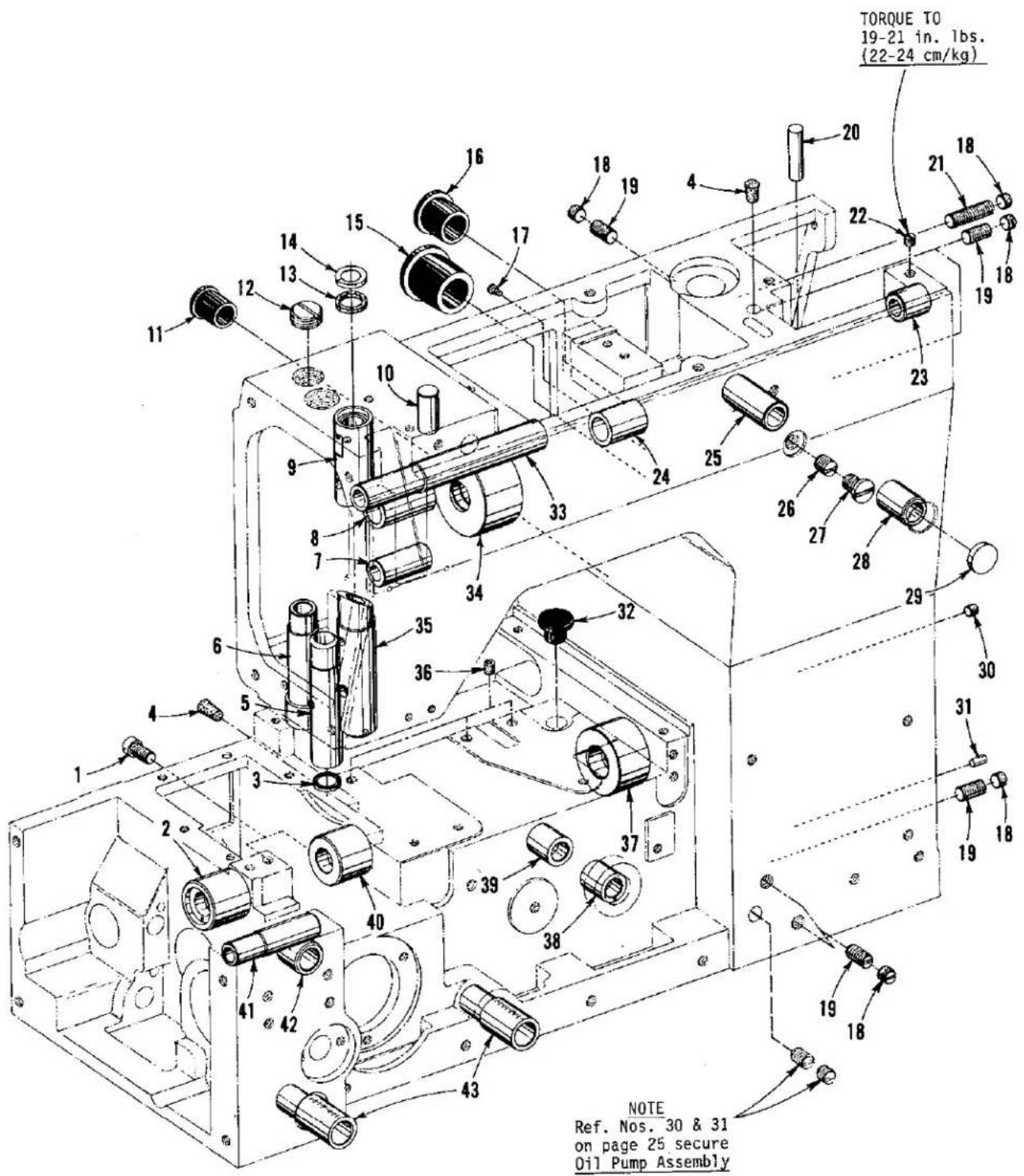
text_image
TORQUE TO 19-21 in. lbs. (22-24 cm/kg) NOTE Ref. Nos. 30 & 31 on page 25 secure Oil Pump AssemblyP116
MAIN FRAME BUSHINGS AND PLUGS
| Ref.No. | PartNo. | Description | Amt.Req. |
| 1 | 136 A | Screw ---- | 2 |
| 2 | 50344 K | Bushing, lower mainshaft ---- | 1 |
| 3 | 660-739 | Seal, oil presser bar bushing ---- | 1 |
| 4 | C067 B | Plug, cork ---- | 2 |
| 5 | C50057 D | Bushing, presser bar ---- | 1 |
| 6 | C50047 C | Bushing, spreader holder shaft ---- | 1 |
| 7 | C50036 AD | Bushing, spreader take up shaft ---- | 1 |
| 8 | C50049 D | Bushing, spreader rocker shaft (left) ---- | 1 |
| 9 | 50354 C | Bushing, needle bar (upper) ---- | 1 |
| 10 | 51-794 BLK. | Plug, aluminum ---- | 1 |
| 11 | C50093 CT | Plug, oil ---- | 1 |
| 12 | 22539 G | Screw, plug ---- | 1 |
| 13 | 666-311 | Screen, needle bar bushing ---- | 1 |
| 14 | C50054 D | Shield, needle bar bushing ---- | 1 |
| 15 | C50093 AX | Plug, oil ---- | 1 |
| 16 | C50093 AY | Plug, oil ---- | 1 |
| 17 | 604 | Screw, plug ---- | 2 |
| 18 | 22586 | Screw, locking ---- | 5 |
| 19 | 74 E | Screw, plug ---- | 4 |
| 20 | 50394 S | Plug, steel ---- | 1 |
| 21 | 22533 A | Screw, plug ---- | 1 |
| 22 | 22764 C | Screw, set ---- | 1 |
| 23 | 50390 C | Bushing, presser foot lifter lever (right) ---- | 1 |
| 24 | C50049 C | Bushing, spreader rocker shaft (right) ---- | 1 |
| 25 | 50390 | Bushing, presser foot lifter lever (rear) ---- | 1 |
| 26 | C50055 H | Screw, set ---- | 1 |
| 27 | 22706 C | Screw, locking ---- | 1 |
| 28 | 50390 A | Bushing, presser foot lifter lever (front) ---- | 1 |
| 29 | 51-627 BLK. | Plug ---- | 1 |
| 30 | 22565 | Screw, plug ---- | 1 |
| 31 | C50093 CN | Plug, aluminum ---- | 1 |
| 32 | C50035 Z | Plug, oil ---- | 1 |
| 33 | 50390 D | Bushing, presser foot lifter lever (left) ---- | 1 |
| 34 | 50355 L | Bushing, upper mainshaft ---- | 1 |
| 35 | 50354 B | Bushing, needle bar (lower) ---- | 1 |
| 36 | 22894 C | Screw, plug ---- | 3 |
| 37 | 50344 L | Bushing, lower mainshaft ---- | 1 |
| 38 | 50344 G | Bushing, take-up shaft (front) ---- | 1 |
| 39 | 50344 F | Bushing, take-up shaft (rear) ---- | 1 |
| 40 | 50344 B | Bushing, lower mainshaft ---- | 1 |
| 41 | 50368 B | Bushing, rear needle guard shaft ---- | 1 |
| 42 | 50344 E | Bushing, looper rocker (rear) ---- | 1 |
| 43 | 35036 AB | Bushing, stitch control shaft ---- | 2 |

text_image
Exploded view diagram of a mechanical assembly with numbered components for identificationSAFETY SHIELD, COVERS AND PLATES
| Ref.No. | PartNo. | Description | Amt.Req. |
| 1 | C50095 S | Shield Assembly, safety | 1 |
| 2 | 12934 A | Nut | 2 |
| 3 | RM2879-2 | Rivet | 2 |
| 4 | 97127 | Washer, spring | 2 |
| 5 | C50095 R | Shield, safety | 1 |
| 6 | C50095 E | Bracket, mounting | 1 |
| 7 | C50095 D | Stud | 1 |
| 8 | C50082 R* | Cover, head | 1 |
| 9 | 660-219 A | Pin, roll (stop) | 1 |
| 10 | C50082 AA | Gasket | 1 |
| 11 | 22883 B | Screw, plug | 1 |
| 12 | 22541 C | Screw | 4 |
| 13 | C50082 AW | Gasket | 1 |
| 14 | C50082 K | Gasket | 1 |
| 15 | C50082 V | Cover, head (left rear) | 1 |
| 16 | 22569 M | Screw | 9 |
| 17 | C50082 M | Cover, head (right rear) | 1 |
| 18 | C50082 N | Gasket | 1 |
| 19 | 22861 C | Screw | 4 |
| 20 | 50382 K | Cover, top | 1 |
| 21 | 22894 J | Screw | 4 |
| 22 | 50394 J | Plug, oil | 4 |
| 23 | C50093 AU | Cap, oil filler | 1 |
| 24 | C50082 X | Gasket | 1 |
| 25 | 50382 F | Gasket | 1 |
| 26 | 22526 H | Screw | 10 |
| 27 | 50382 J | Cover | 1 |
| 28 | 22525 E | Screw | 9 |
| 29 | 22841 N | Screw, adaptor | 1 |
| 30 | 50382 H | Cover | 1 |
| 31 | 87 | Screw | 2 |
| 32 | -- -- | Throat Plate, see "SEWING COMBINATIONS" | 1 |
| 33 | 22839 | Screw | 2 |
| 34 | 35036 AE | Ferrule, locating | 2 |
| 35 | 22587 N | Screw | 2 |
| 36 | 50380 A | Support, throat plate | 1 |
| 37 | 660-939 | Bumper, rubber | 1 |
| 38 | 22799 AH | Stud, latch spring | 1 |
| 39 | 50393 U | Shield, lint | 1 |
| 40 | 94 | Screw | 1 |
| 41 | 22517 | Screw | 4 |
| 42 | 999-216 C | Plug, plastic | 1 |
| 43 | 50382 A | Cover, end | 1 |
| 44 | 22894 D | Screw (bearing) | 2 |
| 45 | 35082 F | Gasket | 1 |
| 46 | 35082 E | Cover, feed chamber (rear) | 1 |
| 47 | 22569 D | Screw | 4 |
| 48 | 50301 B | Support, cloth plate; for Styles LF633K200MM, LF633K200MN | 2 |
| - | 50301 B | Support, cloth plate; for Styles LF632K200MV, LF633K200MW | 1 |
| 49 | 93 | Screw, for Styles LF633K200MM, LF633K200MN | 4 |
| - | 93 | Screw, for Styles LF632K200MV, LF633K200MW | 2 |
| 50 | 50332 E | Support, cloth plate; for Styles LF632K200MV, LF633K200MW | 1 |
| 51 | 22526 | Screw, for Styles LF632K200MV, LF633K200MW | 2 |
| 52 | 50382 D | Gasket | 1 |
| 53 | 50382 E* | Cover, feed chamber (top) | 1 |
| 54 | 22653 B-8 | Screw | 6 |
| 55 | 50301 X | Plate, cloth (left) for Style LF632K200MV | 1 |
| - | 50301 S | Plate, cloth (left) for Styles LF633K200MM, LF633K200MN | 1 |
| - | 50301 U | Plate, cloth (left) for Style LF633K200MW | 1 |
| 56 | 50345 G | Plate, swing; for Style LF632K200MV | 1 |
| - | 50345 D | Plate, swing; for Style LF633K200MW | 1 |
| 57 | 50301 E | Plate, cloth (right) for Styles LF632K200MV, LF633K200MW | 1 |
| - | 50301 | Plate, cloth (right) for Styles LF633K200MM, LF633K200MN | 1 |
| 58 | 92978 | Washer | 1 |
| 59 | 22726 | Screw | 1 |
| * | 21227 | FG Plastic Head Cover F500 & F600 NON Puller Machine | |
| 21227 | FH Plastic Feed Chamber Cover LF, HF, XF 600 M/C |

text_image
TORQUE TO 10-12 in. 1bs. (12-14 cm/kg) TORQUE TO 16-18 in. 1bs. (18-21 cm/kg) TORQUE TO 16 in. 1bs. (18.4 cm/kg) TORQUE TO 14-16 in. 1bs. (16-18 cm/kg)NEEDLE DRIVE (SCOTCH YOKE) AND ASSOCIATED PARTS
| Ref.No. | PartNo. | Description | Amt.Req. |
| 1 | 128 GBS | Needle ---- | 2 or 3 |
| 2 | C50018-8 | Head, needle bar; for Style LF632K200MV-8 ---- | 1 |
| - | C50018 H-12 | Head, needle bar; for Style LF632K200MV-12 ---- | 1 |
| - | C50018 G-16 | Head, needle bar; for Styles LF633K200MM, MN, MW -- | 1 |
| * 3 | C50042 X | Eyelet, thread ---- | 1 |
| 4 | 28 C | Screw, for No. C50018 G-16 ---- | 3 |
| - | 28 C | Screw, for Nos. C50018-8 and C50018 H-12 ---- | 2 |
| 5 | 1059 | Screw, set ---- | 1 |
| 6 | 22561(87U) | Screw ---- | 1 |
| 7 | C50042 AM-12 | Guide, needle thread; for Nos. C50018-8 and C50018 H-12 ---- | 1 |
| - | C50042 AM-14 | Guide, needle thread; for No. C50018 G-16 ---- | 1 |
| 8 | 50355 G | Stud, support ---- | 1 |
| 9 | 22655 B-7 | Screw ---- | 1 |
| 10 | C50017 C | Bar, needle ---- | 1 |
| 11 | 50358 E | Eyelet, needle bar ---- | 1 |
| 12 | 18-71 | Screw ---- | 1 |
| 13 | 22720 C | Screw ---- | 1 |
| 14 | C50094 X | Fitting, male (barbed) ---- | 1 |
| 15 | 50355 U | Scotch Yoke Assembly ---- | 1 |
| 16 | 88 B | Screw ---- | 1 |
| 17 | J80 K | Screw ---- | 1 |
| 18 | 22591 | Screw ---- | 1 |
| 19 | C50093 CJ | Tube, air ---- | 1 |
| 20 | C50093 AY | Plug ---- | 1 |
| 21 | C067 D | Cork ---- | 1 |
| 22 | C50036 P | Bearing and Collar Assembly ---- | 1 |
| 23 | 22894 AD | Screw ---- | 2 |
| 24 | 660-713 | Ring, retaining ---- | 1 |
| 25 | 50355 H | Yoke Assembly ---- | 1 |
| 26 | 22596 E | Screw ---- | 1 |
| 27 | 35093 P | Housing, scotch yoke drive ---- | 1 |
| 28 | 660-708 | "0" Ring ---- | 1 |
| 29 | 660-680 | Seal, lip ---- | 1 |
| 30 | 35042 A | Sprocket, scotch yoke drive ---- | 1 |
| 31 | 22894 X | Screw ---- | 2 |
| 32 | C50021 A | Handwheel ---- | 1 |
| 33 | 22894 C | Screw ---- | 2 |
| 34 | 50342 R | Belt, scotch yoke drive ---- | 1 |
| 35 | 22585 C | Screw ---- | 2 |
| 36 | 53678 N | Washer ---- | 2 |
| 37 | 35042 C | Roller, idler ---- | 2 |
| 38 | 50354 | Stud, idler ---- | 2 |
| 39 | 80630 D | Nut ---- | 2 |
| 40 | 22706 C | Screw, locking ---- | 1 |
| 41 | C50055 H | Screw, set ---- | 1 |
| 42 | 25 S | Screw ---- | 2 |
| * | 50342AA LF | Spreader Machine |
text_image
TORQUE TO 28 in. lbs. (32 cm/kg) TORQUE TO 36 in. lbs. (41 cm/kg)P119
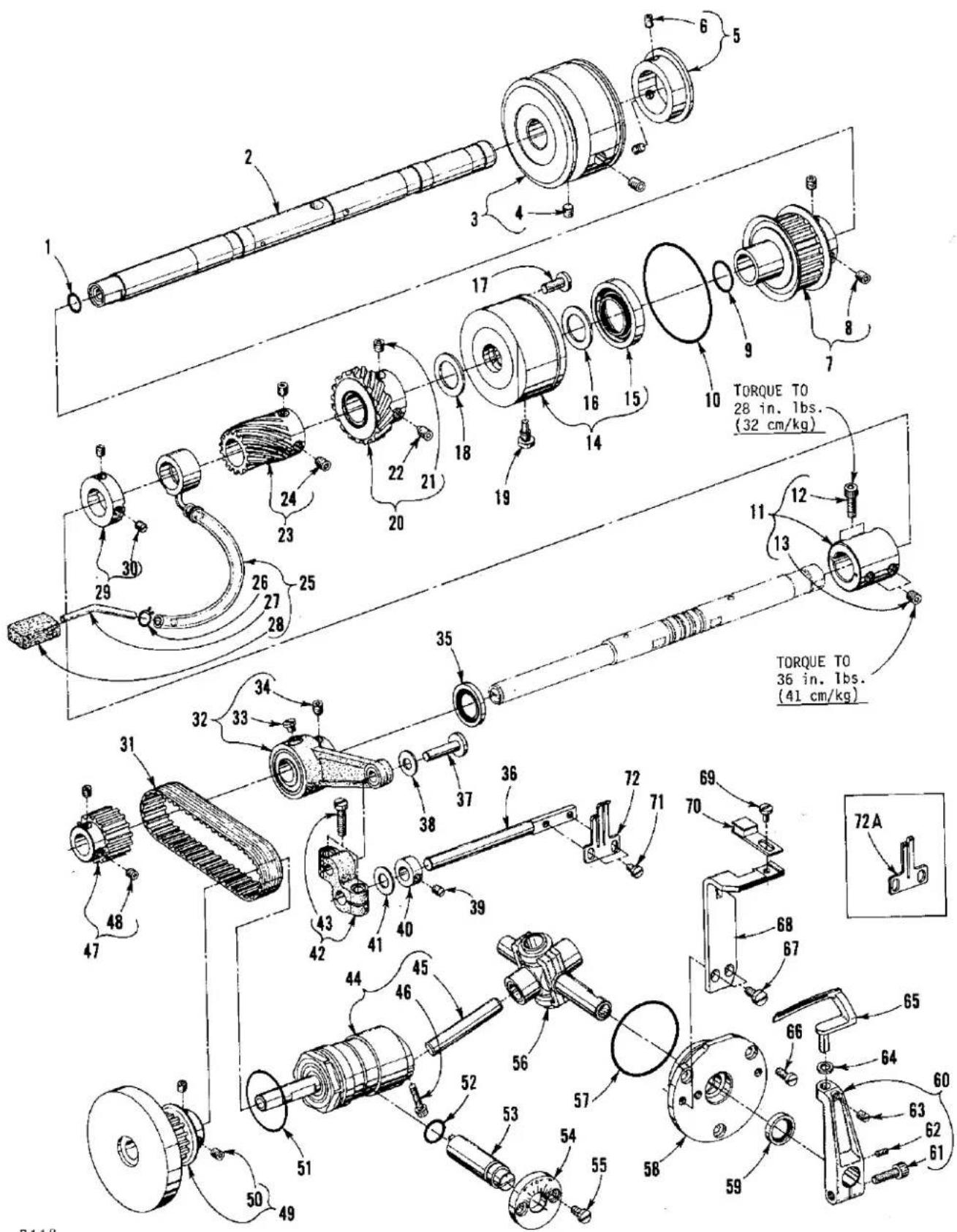
LOWER MAINSHAFT, LOOPER AND REAR NEEDLE GUARD DRIVE
| Ref.No. | PartNo. | Description | Amt.Req. |
| 1 | 660-220 | "0" Ring | 1 |
| 2 | 50322 AA | Mainshaft, lower (right) | 1 |
| 3 | 35021 | Pulley | 1 |
| 4 | 22650 CD-6 | Screw, set | 2 |
| 5 | 35021 B | Guard, pulley | 1 |
| 6 | 22894 C | Screw, set | 2 |
| 7 | 50342 H | Sprocket, lower mainshaft (right) | 1 |
| 8 | 22894 X | Screw | 2 |
| 9 | 660-212 | "0" Ring | 1 |
| 10 | 660-935 | "0" Ring | 1 |
| 11 | 50343 | Coupling, lower mainshaft | 1 |
| 12 | 22652 A-8 | Screw | 2 |
| 13 | 22894 AE | Screw, set | 2 |
| 14 | 50393 S | Housing, lower mainshaft | 1 |
| 15 | 660-998 | Seal, oil | 1 |
| 16 | 35055 V | Washer, thrust | 1 |
| 17 | 25 S | Screw, retaining (lower mainshaft housing) | 2 |
| 18 | 35055 V | Washer (spacer) | 1 |
| 19 | 62245 C | Stud, locating | 1 |
| 20 | 50339 | Gear, oil pump drive (nylon) | 1 |
| 21 | 22894 AD | Screw, set | 1 |
| 22 | 22894 K | Screw, spot | 1 |
| 23 | 50342 D | Gear, take-up drive | 1 |
| 24 | 22894 C | Screw | 2 |
| 25 | 50393 AN | Pump Assembly, oil siphon | 1 |
| 26 | 660-885 | Clamp, tube | 1 |
| 27 | 50393 AL | Tube, brass | 1 |
| 28 | 666-214 | Felt | 1 |
| 29 | 57847 | Collar | 1 |
| 30 | 95 | Screw | 2 |
| 31 | C50042 AD | Belt, looper drive | 1 |
| 32 | 50368 C | Connecting Rod, needle guard | 1 |
| 33 | 22830 | Screw | 1 |
| 34 | 22894 AD | Screw | 2 |
| 35 | 660-934 | Seal, oil | 1 |
| 36 | C50068 AR | Shaft, rear needle guard | 1 |
| 37 | 50368 A | Pin, pivot | 1 |
| 38 | 50368 E | Washer, non-metallic | 1 |
| 39 | 22743 | Screw, for No. 50368 D | 1 |
| 40 | 50368 D | Collar, thrust | 1 |
| 41 | 6042 A | Washer | 1 |
| 42 | 50368 | Connection, rear needle guard pivot | 1 |
| 43 | 22729 | Screw | 2 |
| 44 | 29105 AU | Drive Assembly, looper | 1 |
| 45 | 667 J-33 | Pin, crank | 1 |
| 46 | 22653 J-8 | Screw | 1 |
| 47 | 50342 B | Sprocket, looper drive | 1 |
| 48 | 22894 AD | Screw | 2 |
| 49 | 50342 A | Sprocket, looper driven | 1 |
| 50 | 22894 AD | Screw | 2 |
| 51 | 660-979 | "0" Ring | 1 |
| 52 | 660-206 | "0" Ring | 1 |
| 53 | 50314 | Eccentric, looper avoid adjusting | 1 |
| 54 | 50314 A | Plate, eccentric retaining | 1 |
| 55 | 22569 G | Screw | 2 |
| 56 | 29192 AE | Rocker Assembly, looper | 1 |
| 57 | 660-455 | "0" Ring | 1 |
| 58 | 50344 C | Housing, looper rocker bearing | 1 |
| 59 | C50044 V | Seal, oil | 1 |
| 60 | 50313 | Holder, looper | 1 |
| 61 | 22652 B-10 | Screw, binder | 1 |
| 62 | 22575 B | Screw, adjusting | 1 |
| 63 | 22565 | Screw, set | 1 |
| 64 | 21210 | Collar, looper | 1 |
| 65 | 50309 | Looper | 1 |
| 66 | 22569 G | Screw | 3 |
| 67 | 22569 C | Screw | 2 |
| 68 | 50325 D | Holder, front needle guard | 1 |
| 69 | 90 | Screw | 1 |
| 70 | 50325 F | Guard, front; for Style LF632K200MV | 1 |
| 50325 G | Guard, front; for Styles LF633K200MM, MN, MN | 1 | |
| 71 | 90 | Screw | 2 |
| 72 | C50025 J | Guard, needle, rear; for all Styles except LF632K200MV | 1 |
| 72A | 50325 B | Guard, needle, rear; for Style LF632K200MV | 1 |

text_image
Technical diagram of a mechanical assembly with numbered components and exploded viewsP120
LOOPER THREAD CAST-OFF AND DRIVING PARTS
| Ref.No. | PartNo. | Description | Amt.Req. |
| 1 | 22781 | Screw ---- | 1 |
| 2 | 53678 N | Washer ---- | 1 |
| 3 | 50332 | Spring, latch ---- | 1 |
| 4 | 50357 A | Bracket, mounting ---- | 1 |
| 5 | 22569 D | Screw ---- | 3 |
| 6 | 50357 C | Plate Assembly, cast-off support ---- | 1 |
| 7 | 22588 S | Screw ---- | 1 |
| 8 | 52904 E | Bracket, retaining finger support ---- | 1 |
| 9 | 22768 | Screw ---- | 1 |
| 10 | 52804 E | Support, retaining finger ---- | 1 |
| 11 | 50304 C | Finger, retaining ---- | 1 |
| 12 | 73 A | Screw ---- | 4 |
| 13 | 52958 D | Eyelet ---- | 2 |
| 14 | 157-15 | Washer ---- | 2 |
| 15 | 50323 D | Strike-off ---- | 1 |
| 16 | 50357 | Plate, cast-off support ---- | 1 |
| 17 | 22588 A | Screw ---- | 1 |
| 18 | 50357 G | Knife, anti-wrap up (back) ---- | 1 |
| 19 | 50357 H | Knife, anti-wrap up (front) ---- | 1 |
| 20 | 22798 | Screw ---- | 2 |
| 21 | 99521 | Washer, spring ---- | 2 |
| 22 | 50357 D | Screw, shoulder ---- | 1 |
| 23 | 50323 E | Take-Up Assembly ---- | 1 |
| 24 | 22894 C | Screw ---- | 2 |
| 25 | 50323 B | Hub ---- | 1 |
| 26 | C50323 D | Disc, take-up ---- | 2 |
| 27 | C50077 P | Spacer ---- | 1 |
| 28 | 22797 B | Screw ---- | 2 |
| 29 | 50323 C | Collar, positioning ---- | 1 |
| 30 | 22894 C | Screw ---- | 1 |
| 31 | 50342 F | Shaft, take-up ---- | 1 |
| 32 | 89 | Screw ---- | 1 |
| 33 | 660-986 | Seal, lip ---- | 1 |
| 34 | 50344 H | Collar, thrust ---- | 1 |
| 35 | 22894 C | Screw ---- | 2 |
| 36 | 54274 P | Washer, thrust ---- | 2 |
| 37 | 50342 E | Gear, take-up (driven) ---- | 1 |
| 38 | 22894 C | Screw, set ---- | 1 |
| 39 | 22894 D | Screw, spot ---- | 1 |
| 40 | 50357 F | Guard, take-up disc ---- | 1 |

text_image
Technical diagram of a mechanical assembly with numbered components for identification and assembly reference.P121
MAIN FEED DRIVE AND STITCH REGULATING PARTS
| Ref.No. | PartNo. | Description | Amt.Req. |
| 1 | 50322 | Mainshaft, lower (left) ---- | 1 |
| 2 | 22591 | Screw ---- | 1 |
| 3 | 999-211 C | "0" Ring ---- | 1 |
| 4 | 22591 A | Screw, set ---- | 2 |
| 5 | 35034 N | Shaft, rocker ---- | 1 |
| 6 | 35034 J | Stud, eccentric ---- | 1 |
| 7 | 35034 F | Rocker, feed (main) ---- | 1 |
| 8 | 22596 E | Screw ---- | 1 |
| 9 | 22571 D | Screw, plug ---- | 1 |
| 10 | 35034 M | Bushing, rocker shaft ---- | 1 |
| 11 | 29126 FB | Fork Assembly, driving (main) ---- | 1 |
| 12 | 35040 B-15 | Eccentric, double (main) ---- | 1 |
| 13 | 22894 J | Screw ---- | 2 |
| 14 | 661-50 | Washer, cup ---- | 1 |
| 15 | 35036 F | Bushing, stitch adjusting shaft ---- | 1 |
| 16 | 35036 AZ | Pad, brake ---- | 1 |
| 17 | 22894 AB | Screw ---- | 1 |
| 18 | 35036 C | Shaft Assembly, main feed stitch adjusting ---- | 1 |
| 19 | 50335 | Retainer, spring ---- | 1 |
| 20 | 22714 C | Screw, tension (feed adjusting) ---- | 1 |
| 21 | 50355 | Spring ---- | 1 |
| 22 | 50335 A | Holder, spring ---- | 1 |
| 23 | 50336 D | Lever, stitch control (main feed) ---- | 1 |
| 24 | 661-35 | Pin ---- | 1 |
| 25 | 22596 E | Screw ---- | 2 |
| 26 | 50335 C | Cam, roller ---- | 1 |
| 27 | 77 K | Screw ---- | 1 |
| 28 | 35036 AP | Knob, stitch adjusting shaft ---- | 1 |
| 29 | 22764 A | Screw ---- | 1 |
| 30 | 660-206 | "0" Ring ---- | 1 |
| 31 | 50335 E | Shaft, stitch control ---- | 1 |
| 32 | 660-980 | "0" Ring ---- | 1 |
| 33 | 50335 D | Collar, stitch length stop ---- | 2 |
| 34 | 22560 B | Screw ---- | 2 |
text_image
Technical schematic diagram of a mechanical assembly with numbered components and labeled partsDIFFERENTIAL FEED DRIVE AND REGULATING PARTS
| Ref. No. | Part No. | Description | Amt. Req. |
| 1 | 22894 AB | Screw ---- | 1 |
| 2 | 661-50 | Washer, cup ---- | 1 |
| 3 | 660-969 | "0" Ring ---- | 1 |
| 4 | 35036 F | Bushing, stitch adjusting shaft ---- | 1 |
| 5 | 660-220 | "0" Ring ---- | 1 |
| 6 | 35036 AZ | Pad, brake ---- | 1 |
| 7 | 35036 C | Shaft Assembly, differential feed stitch adjusting | 1 |
| 8 | 35034 G | Rocker, feed (differential) ---- | 1 |
| 9 | 22596 E | Screw ---- | 1 |
| 10 | 35034 J | Stud, eccentric ---- | 1 |
| 11 | 35040 A-15 | Eccentric, double (differential) ---- | 1 |
| 12 | 22894 J | Screw ---- | 2 |
| 13 | 29126 FA | Fork Assembly, driving (differential) ---- | 1 |
| 14 | 29126 EU | Feed Bar Assembly (includes main, differential feed bars, and blocks) ---- | 1 |
| 15 | 22569 AD | Screw ---- | 2 |
| 16 | -- -- | Feed Dog, differential; see "SEWING COMBINATIONS" - | 1 |
| 17 | 50334 H | Holder, differential feed dog ---- | 1 |
| 18 | 22729 L | Screw ---- | 2 |
| 19 | 50334 G | Holder, main feed dog ---- | 1 |
| 20 | 22637 P-24 | Screw ---- | 1 |
| 21 | -- -- | Feed Dog, main; see "SEWING COMBINATIONS" ---- | 1 |
| 22 | 99277 | Screw, stabilizing ---- | 1 |
| 23 | 22617 J-16 | Screw ---- | 10 |
| 24 | 35034 E | Guide, feed bar (front) ---- | 1 |
| 25 | 50334 AD | Seal, feed bar (front) ---- | 1 |
| 26 | 35034 D | Guide, feed bar (rear) ---- | 1 |
| 27 | 50334 AC | Seal, feed bar (rear) ---- | 1 |
| 28 | 50334 V | Scraper, rear oil ---- | 1 |
| 29 | 50334 Y | Baffle, rear oil plate ---- | 1 |
| 30 | 50367 D | Lever, stitch control (differential feed) ---- | 1 |
| 31 | 22596 E | Screw ---- | 1 |
| 32 | 661-35 | Pin ---- | 1 |
| 33 | 50335 | Retainer, spring ---- | 1 |
| 34 | 22714 C | Screw, tension (feed adjusting) ---- | 1 |
| 35 | 50355 | Spring ---- | 1 |
| 36 | 50335 A | Holder, spring ---- | 1 |
| 37 | 77 K | Screw ---- | 1 |
| 38 | 50335 C | Cam, roller ---- | 1 |
| 39 | 660-206 | "0" Ring ---- | 1 |
| 40 | 35036 AP | Knob, stitch adjusting shaft ---- | 1 |
| 41 | 22764 A | Screw ---- | 1 |
| 42 | 50335 E | Shaft, stitch control ---- | 1 |
| 43 | 660-980 | "0" Ring ---- | 1 |
| 44 | 50335 D | Collar, stitch length stop ---- | 2 |
| 45 | 22560 B | Screw ---- | 2 |

text_image
TORQUE TO 35 in. 1bs. (40 cm/kg) 17 18 20 19 16 17 14 15 13 12 10 11 9 25 26 24 23 22 21 28 27 29 30 32 31 30 39 38 37 36 35 34 33 40 46 45 63 62 61 54 44 43 45 46 45 43 42 41 39 41 40 66 59 58 57 56 55 54 53 52 51 50 49 48 47 46 45 44 43 42 1 2 3 4 5 6 7SPREADER AND SPREADER DRIVING MECHANISM
| Ref. No. | Part No. | Description | Amt. Req. |
| 1 | 57845 AA | Spreader ---- | 1 |
| 2 | C50046 | Holder, spreader ---- | 1 |
| 3 | 94 | Screw ---- | 2 |
| 4 | 77 | Screw ---- | 2 |
| 5 | 660-739 | Seal, oil ---- | 1 |
| 6 | C50047 B | Shaft, spreader holder ---- | 1 |
| 7 | C50047 D | Lever, spreader holder shaft ---- | 1 |
| 8 | 88 A | Screw ---- | 2 |
| 9 | C50047 F | Pin, Link ---- | 1 |
| 10 | C50049 E | Arm, rocker shaft ---- | 1 |
| 11 | 22548 | Screw ---- | 1 |
| 12 | WO-2 | Yarn, Columbia, 6 strands, 6 inches (152.4mm) long ---- | 1 |
| 13 | C50049 B | Shaft, spreader rocker ---- | 1 |
| 14 | 56335 D | Collar, thrust ---- | 1 |
| 15 | 95 | Screw ---- | 2 |
| 16 | 18 | Nut ---- | 1 |
| 17 | 53636 C | Washer ---- | 2 |
| 18 | C50052 | Lever, rocker shaft ---- | 1 |
| 19 | 22894 X | Screw ---- | 1 |
| 20 | C50052 A | Stud, connecting ---- | 1 |
| 21 | 29126 EM | Spreader Drive Eccentric Assembly ---- | 1 |
| 22 | 22894 J | Screw ---- | 2 |
| 23 | C50036 AC | Washer, thrust ---- | 1 |
| 24 | 999-215 | Ring, retaining ---- | 1 |
| 25 | C50092 Z | Take-up, spreader thread ---- | 1 |
| 26 | 88 A | Screw ---- | 1 |
| 27 | C50092 Y | Arm, driving lever ---- | 1 |
| 28 | 22894 W | Screw ---- | 1 |
| 29 | 660-966 | Seal, oil ---- | 1 |
| 30 | C50092 X | Shaft ---- | 1 |
| 31 | C50036 AE | Collar, thrust ---- | 1 |
| 32 | 28 C | Screw ---- | 2 |
| 33 | 39592 AA | Nut, spreader tension ---- | 1 |
| 34 | 39592 AK | Ferrule, tension spring ---- | 1 |
| 35 | 50392 M | Spring, tension, spreader thread ---- | 1 |
| 36 | 39592 AD | Disc, tension ---- | 2 |
| 37 | 39592 AF | Felt, tension disc ---- | 1 |
| 38 | C50092 AC | Post, tension ---- | 1 |
| 39 | C50092 T | Eyelet, tension ---- | 1 |
| 40 | 39592 AH | Nut, tension post ---- | 1 |
| 41 | C50044 N | Bracket, mounting ---- | 1 |
| 42 | 22882 | Screw ---- | 1 |
| 43 | C50044 M | Plate, spreader guide ---- | 1 |
| 44 | 22716 A | Screw ---- | 2 |
| 45 | 35032 H | Washer ---- | 2 |
| 46 | 22519 | Screw ---- | 2 |
| 47 | C50044 U | Guide, spreader thread ---- | 1 |
| 48 | 22825 | Screw ---- | 1 |
| 49 | 605 A | Screw ---- | 2 |
| 50 | C50092 U | Post, nipper (base) ---- | 1 |
| 51 | 57 WB | Plate, spring ---- | 1 |
| 52 | 15438 C | Spring ---- | 1 |
| 53 | 51959 D | Nut, tension ---- | 1 |
| 54 | 29475 BT | Spreader Thread Tension Assembly ---- | 1 |
| 55 | 57892 B | Nut, spreader tension post ---- | 1 |
| 56 | 39592 AR-1 | Spring, tension ---- | 1 |
| 57 | 39592 AD | Disc, tension ---- | 2 |
| 58 | C50036 AF | Post, spreader tension ---- | 1 |
| 59 | 41071 G | Nut ---- | 1 |
| 60 | C50092 W | Guide, spreader thread ---- | 1 |
| 61 | C50044 T | Plate, mounting; thread guide ---- | 1 |
| 62 | 22766 | Screw ---- | 2 |
| 63 | C50092 V | Bracket, spreader tension post ---- | 1 |

text_image
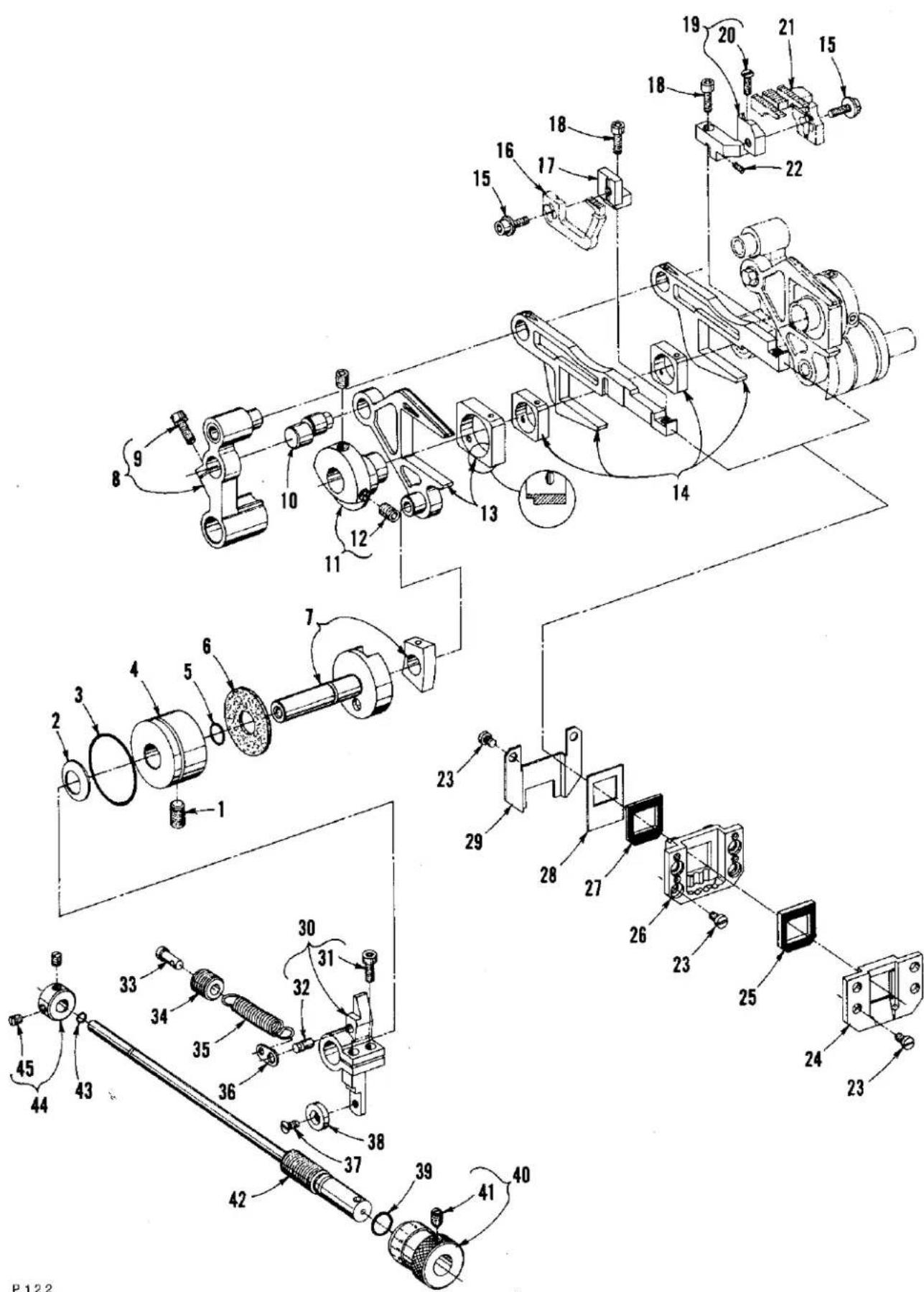
Exploded view diagram of a mechanical assembly with numbered components and labeled partsFRONT COVER AND THREAD HANDLING PARTS
| Ref. No. | Part No. | Description | Amt. Req. |
| 1 | 51758 | Eyelet, spreader thread | 1 |
| 2 | 50358 C | Wire, needle thread control (front) | 1 |
| 3 | 50358 B | Wire, needle thread control (middle) | 1 |
| 4 | 50358 A | Wire, needle thread control (rear) | 1 |
| 5 | 50358 D | Holder, wire | 1 |
| 6 | 73 B | Screw | 6 |
| 7 | C50054 M | Guard, needle bar eyelet | 1 |
| 8 | 22569 C | Screw | 3 |
| 9 | C50092 S | Nut, thread tension | 3 or 4 |
| 10 | 39592 AK | Ferrule, tension spring | 3 or 4 |
| 11 | 39592 AR-5 | Spring, needle thread tension | 2 or 3 |
| 12 | 22569 C | Screw | 2 |
| 13 | 29476 PG | Needle Thread Control Assembly | 1 |
| 14 | C50058 R | Nut | 1 |
| 15 | C50004 C | Plate, needle thread control | 1 |
| 16 | 56358 D | Spacer | 1 |
| 17 | 51858 | Eyelet, adjustable | 1 |
| 18 | 22757 | Screw | 1 |
| 19 | C50092 J | Pin, thread tension release | 2 or 3 |
| 20 | C50092 L | Post, tension | 3 or 4 |
| 21 | 109 | Disc, tension | 6 or 8 |
| 22 | 56392 F | Shield, tension spring | 3 or 4 |
| 23 | C50092 M | Washer, tension release | 2 or 3 |
| 24 | 51292 A | Ferrule, tension post | 3 or 4 |
| 25 | C50092 R | Washer | 3 or 4 |
| 26 | 50392 B | Housing, tension assembly | 3 or 4 |
| 27 | C50092 G | Pin, tension release actuating | 2 or 3 |
| 28 | 18-799 | Screw | 2 or 3 |
| 29 | 22501 A | Screw | 5 |
| 30 | 660-257 | Gasket | 5 |
| 31 | 39592 AR-1 | Spring, looper thread tension | 1 |
| 32 | 50392 | Guide, thread | 1 |
| 33 | C50082 AH | Plug, top cover (rubber), for Style LF632K200MV | 1 |
| 34 | 22569 D | Screw | 2 |
| 35 | 50358 | Eyelet, looper thread | 1 |
| 36 | 50332 D | Bracket, support; for Styles LF632K200MV, LF633K200MW | 1 |
| 36A | 50332 B | Bracket, support; for Styles LF633K200MM, LF633K200MN | 1 |
| 37 | 22799 AH | Stud, latch spring | 2 |
| 38 | 22569 C | Screw | 2 |
| 39 | 50332 A | Spring, latch | 2 |
| 40 | 50382 P | Cover, front; for Styles LF632K200MV, LF633K200MW | 1 |
| 40A | 50382 AL | Cover, front; for Styles LF633K200MM, LF633K200MN | 1 |
| 41 | 22513 | Screw | 7 |
| 42 | 50343 A | Plate, for folder on Styles LF632K200MV, LF633K200MW | 1 |
| 43 | 22704 | Screw, for Styles LF632K200MV, LF633K200MW | 2 |
| 44 | 35569 J | Nut | 1 |
| 45 | 22561 | Screw, for Styles LF632K200MV, LF633K200MW | 2 |
| 46 | 50303 A | Guide, edge; for Styles LF632K200MV, LF633K200MW | 1 |
| 47 | 94 | Screw | 2 |
| 48 | 50382 N | Shield | 1 |
| 49 | 50364 F | Platform | 1 |
| 50 | 22792 A | Screw, adjustable | 4 |
| 51 | 50378 | Hinge, front cover | 2 |
| 52 | 22569 B | Screw | 4 |
| 53 | 661-26 | Bumper, rubber | 4 |
| 54 | 22519 J | Screw | 2 |
| 55 | 50393 W | Bumper, rubber | 2 |
| 56 | 50382 T | Stop, adjustable | 2 |
| 57 | 20 | Washer | 2 |
| 58 | 22569 D | Screw | 1 |
| 59 | 50392 A | Eyelet, looper thread | 1 |
| 60 | C50058 F | Wire, rubbing, needle thread | 1 |
text_image
Technical diagram of a mechanical assembly with numbered components for identification and assembly reference.P125
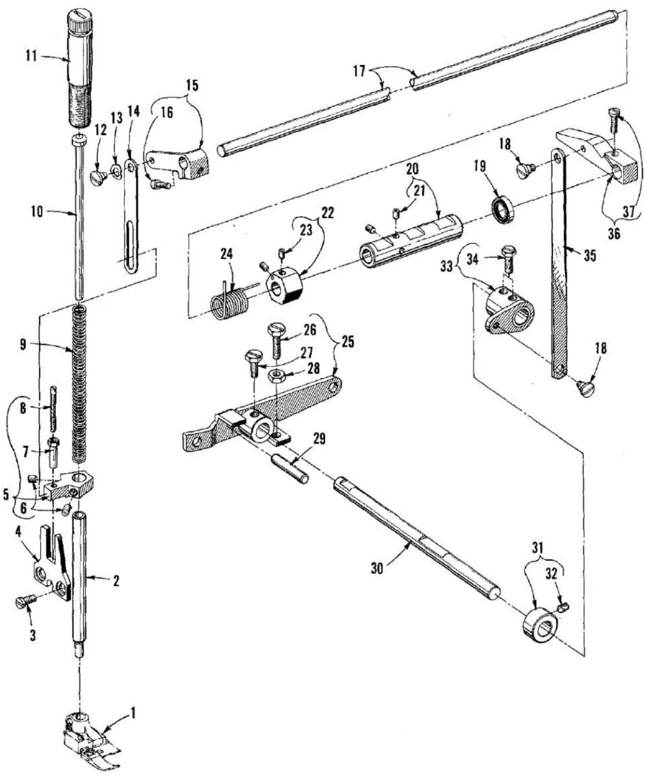
PRESSER FOOT AND TENSION RELEASE PARTS
| Ref. No. | Part No. | Description | Amt. Req. |
| 1 | --- | Presser Foot Assembly, see "SEWING COMBINATIONS" ---- | 1 |
| 2 | C50057 E | Bar, presser ---- | 1 |
| 3 | 22569 C | Screw ---- | 2 |
| 4 | C50067 K | Plate, presser bar guide ---- | 1 |
| 5 | C50056 K | Guide, presser bar ---- | 1 |
| 6 | 531 | Screw ---- | 2 |
| 7 | C50056 J | Nut, lock ---- | 1 |
| 8 | 22840 C | Screw, adjusting ---- | 1 |
| 9 | C50056 C | Spring, presser bar ---- | 1 |
| 10 | C50056 B | Guide, presser bar spring ---- | 1 |
| 11 | C50056 D | Regulator, presser bar spring ---- | 1 |
| 12 | 22758 | Screw ---- | 1 |
| 13 | 660-718 | Washer, spring ---- | 1 |
| 14 | 50367 E | Link, presser foot lift ---- | 1 |
| 15 | C50067 G | Lever, presser foot lift (upper left) ---- | 1 |
| 16 | 22596 E | Screw ---- | 1 |
| 17 | 50322 B | Shaft, presser foot lift (upper) ---- | 1 |
| 18 | 22758 | Screw ---- | 2 |
| 19 | 660-986 | Seal, oil ---- | 1 |
| 20 | 50390 B | Sleeve, tension release ---- | 1 |
| 21 | 22894 W | Screw ---- | 2 |
| 22 | C50090 M | Collar, tension release adjusting ---- | 1 |
| 23 | 22894 P | Screw ---- | 2 |
| 24 | 50390 E | Spring, tension release return ---- | 1 |
| 25 | 50367 A | Lever, presser foot lift (outer) ---- | 1 |
| 26 | 22596 | Screw ---- | 1 |
| 27 | 22882 | Screw ---- | 1 |
| 28 | 12934 A | Nut, locking ---- | 1 |
| 29 | 667 M-14 | Pin, dowel (lifter lever stop) ---- | 1 |
| 30 | 50322 C | Shaft, presser foot lift (lower) ---- | 1 |
| 31 | C50036 R | Collar, thrust ---- | 1 |
| 32 | 22894 L | Screw, spot ---- | 1 |
| 33 | 50367 | Lever, presser foot lift (lower) ---- | 1 |
| 34 | 22882 | Screw ---- | 2 |
| 35 | 50367 B | Connection, presser foot lift ---- | 1 |
| 36 | C50067 B | Lever, presser foot lift (upper right) ---- | 1 |
| 37 | 22596 | Screw ---- | 1 |

text_image
Exploded view diagram of a mechanical assembly with numbered parts for identification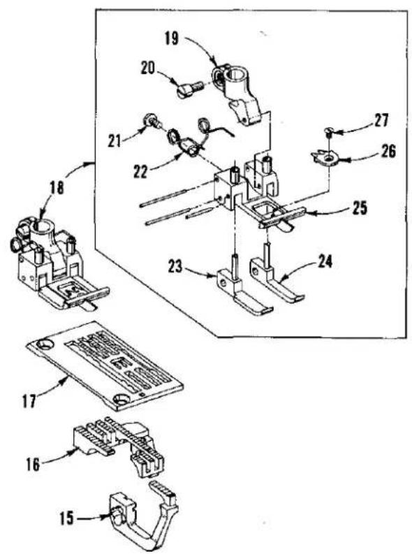
text_image
Technical diagram of an electrical component assembly with numbered parts for identification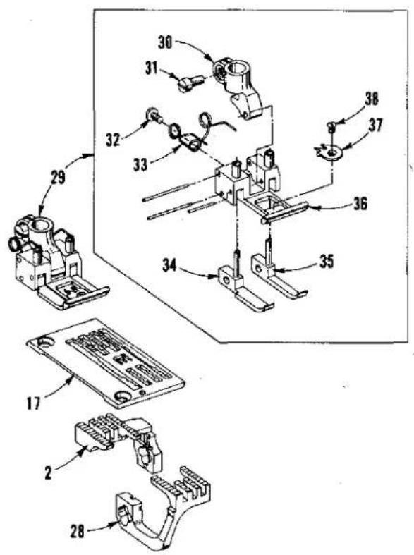
text_image
Technical diagram of a mechanical assembly with numbered parts, likely for assembly or maintenance instructions.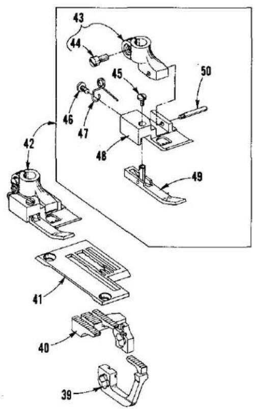
text_image
Technical diagram of mechanical assembly with numbered parts, likely a valve or clamp mechanismP126
SEWING COMBINATIONS
| Ref.No. | PartNo. | Description | Amt.Req. |
| 1 | 50326 E | Feed Dog, differential; for Style LF632K200MV ---- | 1 |
| 2 | 50305 E | Feed Dog, main; for Styles LF632K200MV, LF633K200MN | 1 |
| 3 | C57824 A-8 | Throat Plate, for Style LF632K200MV-8 ---- | 1 |
| - | C57824 A-12 | Throat Plate for Style LF632K200MV-12 ---- | 1 |
| 4 | 52820 H-8 | Presser Foot, for Style LF632K200MV-8 ---- | 1 |
| - | 52820 H-12 | Presser Foot, for Style LF632K200MV-12 ---- | 1 |
| 5 | 13130 B | Shank, presser foot ---- | 1 |
| 6 | 91 | Screw ---- | 1 |
| 7 | 73 A | Screw ---- | 1 |
| 8 | 605 | Screw ---- | 1 |
| 9 | 11534 | Spring ---- | 1 |
| 10 | 52830 H-8 | Bottom, presser foot, for No. 52820 H-8 ---- | 1 |
| - | 52830 H-12 | Bottom, presser foot, for No. 52820 H-12 ---- | 1 |
| 11 | 52830 C | Section, yielding ---- | 1 |
| 12 | 52830 D | Guide, adjustable ---- | 1 |
| 13 | 22561 | Screw ---- | 1 |
| 14 | 22799 B | Screw, hinge ---- | 1 |
| 15 | 50326 | Feed Dog, differential; for Style LF633K200MM ---- | 1 |
| 16 | 50305 | Feed Dog, main; for Style LF633K200MM ---- | 1 |
| 17 | C57824 E-16 | Throat Plate, for Styles LF633K200MM, LF633K200MN -- | 1 |
| 18 | 57820-16 | Presser Foot, for Style LF633K200MM ---- | 1 |
| 19 | G65-134 | Shank, presser foot ---- | 1 |
| 20 | 91 | Screw ---- | 1 |
| 21 | 605 | Screw ---- | 1 |
| 22 | 79633 | Spring ---- | 1 |
| 23 | 57830 B | Section, yielding (left) ---- | 1 |
| 24 | 57830 A | Section, yielding (right) ---- | 1 |
| 25 | 57830-16 | Bottom, presser foot ---- | 1 |
| 26 | G52897 A-16 | Tongue, stitch ---- | 1 |
| 27 | 22716 A | Screw ---- | 1 |
| 28 | 50326 D | Feed Dog, differential; for Style LF633K200MN ---- | 1 |
| 29 | 57820 A-16 | Presser Foot, for Style LF633K200MN ---- | 1 |
| 30 | G65-134 | Shank, presser foot ---- | 1 |
| 31 | 91 | Screw ---- | 1 |
| 32 | 605 | Screw ---- | 1 |
| 33 | 79633 | Spring ---- | 1 |
| 34 | 57830 B | Section, yielding (left) ---- | 1 |
| 35 | 57830 A | Section, yielding (right) ---- | 1 |
| 36 | 57830 C-16 | Bottom, presser foot ---- | 1 |
| 37 | G52897 A-16 | Tongue, stitch ---- | 1 |
| 38 | 22716 A | Screw ---- | 1 |
| 39 | 50326 C | Feed Dog, differential; for Style LF633K200MW ---- | 1 |
| 40 | 50305 D | Feed Dog, main; for Style LF633K200MW ---- | 1 |
| 41 | C52828 K-16 | Throat Plate, for Style LF633K200MW ---- | 1 |
| 42 | 52820 K-16 | Presser Foot, for Style LF633K200MW ---- | 1 |
| 43 | 13130 B | Shank, presser foot ---- | 1 |
| 44 | 91 | Screw ---- | 1 |
| 45 | 73 A | Screw ---- | 1 |
| 46 | 605 | Screw ---- | 1 |
| 47 | 11534 | Spring ---- | 1 |
| 48 | 52830 K-16 | Bottom, presser foot ---- | 1 |
| 49 | 13130 A | Section, yielding ---- | 1 |
| 50 | 22799 B | Screw ---- | 1 |

text_image
Technical diagram of a mechanical assembly with numbered components for identification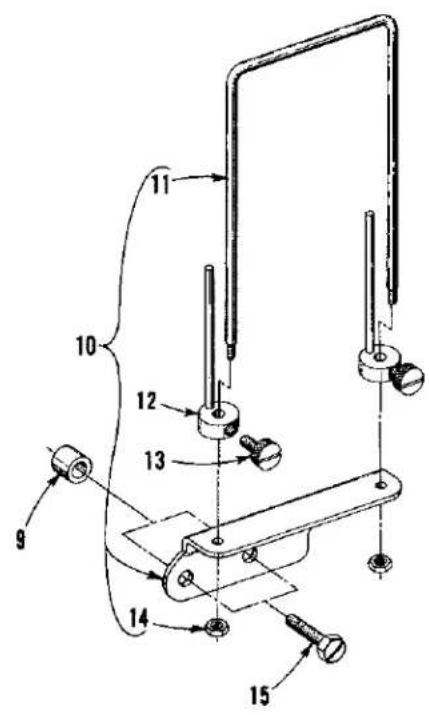
text_image
Technical diagram of a mechanical device with numbered components for identification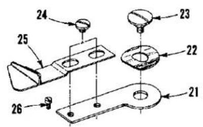
text_image
Technical diagram of a mechanical assembly with numbered parts for identification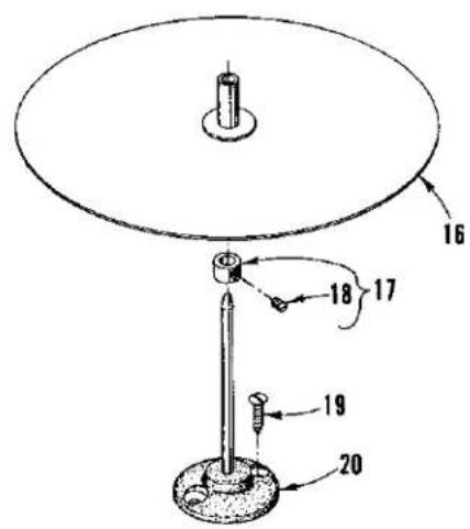
text_image
16 17 18 19 20P127
ATTACHMENTS AND ASSOCIATED PARTS
(FOR STYLES LF632K200MV and LF633K200MW)
| Ref.No. | PartNo. | Description | Amt.Req. |
| 1 | 25 CC | Screw | 2 |
| 2 | 92127 | Screw | 1 |
| 3 | 23432 B | Clamp, folder | 1 |
| 4 | 22882 | Screw | 2 |
| 5 | 50364 E | Washer, plate | 1 |
| 6 | 50364 | Holder, folder | 1 |
| 7 | Folder (See Chart Below) | 1 | |
| 8 | Folder (See Chart Below) | 1 | |
| 9 | 50392 D | Spacer | 2 |
| 10 | 23439 G | Strip Tension Assembly | 1 |
| 11 | 51-561 BLK. | Guide | 1 |
| 12 | 23439 E | Pin, adjustable | 2 |
| 13 | 188 D | Screw | 2 |
| 14 | 907 | Nut | 2 |
| 15 | 627 A | Screw | 2 |
| 16 | 21169 E | Disc, binding holder | 1 |
| 17 | 161 | Collar, stop | 1 |
| 18 | 88 | Screw | 1 |
| 19 | SC303 | Screw, wood | 2 |
| 20 | 21169 F | Base, disc holder | 1 |
| (FOR STYLES LF633K200MM and LF633K200MN) | |||
| 21 | 79603 A | Support, guide | 1 |
| 22 | 898 A-3 | Washer, spring | 1 |
| 23 | 898 A-4 | Screw | 1 |
| 24 | 99252 | Screw | 2 |
| 25 | 50303 | Guide, edge | 1 |
| 26 | 22564 D | Screw, stop | 1 |
TABLE OF FOLDERS
| Ref. No. | Part No. | Machine Style Used on | Seam Type | Strip Size | Finish Size | Strip Capacity | |
| 14 | 23406 R-1/223406 R-5/823406 U-3/423406 S-3/4K5905523406 T-7/8K6404923406 T-1K64050 | MV-8-1/2MV-8-5/8MV-8-3/4MV-8-3/4MV-8-7/8MV-8-7/8MV-8-1MV-8-1MV-8-1-1/4 | MV-12-1/2MV-12-5/8MV-12-3/4MV-12-3/4MV-12-7/8MV-12-7/8MV-12-1MV-12-1MV-12-1-1/4 | BSb-1BSb-1BSb-1BSb-1BSb-1BSb-1BSb-1BSb-1BSb-1BSb-1BSb-1BSb-1BSb-1BSb-1BSb-1BSb-1BSb-1BSb-1BSb-1BSb-1BSb-1BSb-1BSb-1BSb-1BSb-1BSb- | 1-1/4"(31.8mm)1-1/2"(38.1mm)1-3/4"(44.4mm)1-13/16"(46.0mm)2-1/8"(54.0mm)2"(50.8mm)2-1/4"(57.2mm)2-1/4"(57.2mm)2-3/4"(69.8mm) | 1/2"(12.7mm)Top*5/8"(15.9mm)Top*3/4"(19.0mm)Top*3/4"(19.0mm)Top*7/8"(22.2mm)Top*7/8"(22.2mm)Top*1"(25.4mm)Top*1"(25.4mm)Top*1-1/4"(31.8mm)Top* | 3/64"(1.2mm)3/64"(1.2mm)3/64"(1.2mm)5/64"(2.0mm)3/64"(1.2mm)5/64"(2.0mm)3/64"(1.2mm)5/64"(2.0mm)5/64"(2.0mm) |
| 15 | 23406 N-3/423406 N-7/823406 N-123406 N-1-1/4 | MW-16-3/4MW-16-7/8MW-16-1MW-16-1-1/4 | BSa-1BSa-1BSa-1BSa-1 | 1-1/2"(38.1mm)1-3/4"(44.4mm)2"(50.8mm)2-1/2"(63.5mm) | 3/4"(19.0mm)7/8"(22.2mm)1"(25.4mm)1-1/4"(31.8mm) | 5/64"(2.0mm)5/64"(2.0mm)5/64"(2.0mm)5/64"(2.0mm) | |
* Above folders, producing seam Type BSb-1, finish 1/16" (1.6mm) wider on top than on bottom with 1/16" (1.6mm) margin to the left of left hand needle.
natural_image
Technical line drawing of mechanical assembly with multiple components and mounting holes (no text or symbols)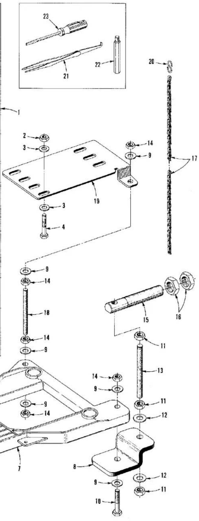
text_image
Technical diagram of a mechanical assembly with numbered parts and exploded views, likely for assembly or manufacturing purposes.P126
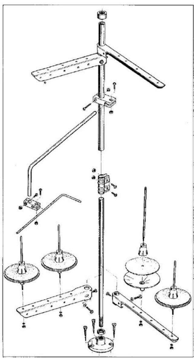
THREAD STAND AND ACCESSORIES
| Ref. No. | Part No. | Description | Amt. Req. |
| 1 | 21101 W-4 | Thread Stand Assembly, for 4-thread machines | 1 |
| - | 21101 W-5 | Thread Stand Assembly, for 5-thread machines | 1 |
| 2 | 50335 T | Nut | 1 |
| 3 | 652-16 | Washer | 6 |
| 4 | 22788 H | Bolt | 3 |
| 5 | 35095 B | Isolator | 4 |
| 6 | 21374 AP | Support | 2 |
| 7 | 21374 AG | Cradle, machine | 1 |
| 8 | 21374 AU | Support | 1 |
| 9 | RM3293-3 | Washer | 14 |
| 10 | 22641 | Bolt | 5 |
| 11 | RM3211-5 | Nut | 9 |
| 12 | RM3293-4 | Washer | 6 |
| 13 | 21374 AT | Rod, threaded | 3 |
| 14 | RM3211-3 | Nut | 9 |
| 15 | 21374 AM | Rod | 3 |
| 16 | 651 M | Nut | 6 |
| 17 | 421 D-42 | Chain, presser foot lift | 1 |
| 18 | 21371 PY-32 | Rod, threaded | 1 |
| 19 | 21374 BB | Bracket, motor mounting | 1 |
| 20 | 660-264 | Hook, "S" | 2 |
| 21 | 660-240 | Tweizer, thread | 1 |
| 22 | 22841 M | Stand, machine | 4 |
| 23 | 21207 B | Screwdriver | 1 |
| 28604 R | Container of oil, 16 ounces (455 ml.), Spec. 175, (not shown) | 1 |
CHIP CHUTE PARTS
| * 1 | 35078 B | Upper Chip Chute |
| 1 | 39578 AS | Lower Chip Chute |
| 2 | 22652 D10 | Screw |
| 1 | 39578 AP | Top Piece |
| * | 50378 C | Right Angle Chip Chute |
NUMERICAL INDEX OF PARTS
| Part No. | Page No. | Part No. | Page No. | Part No. | Page No. |
| WO-2 | 41 | 651 M | 51 | RM2879-2 | 29 |
| WO-3 | 25 | 652-16 | 51 | RM3211-3 | 51 |
| 18 | 41 | 660-206 | 25,33,37, | RM3211-5 | 51 |
| 18-71 | 31 | 39 | RM3293-3 | 51 | |
| 18-799 | 43 | 660-212 | 33 | RM3293-4 | 51 |
| 20 | 43 | 660-219 A | 29 | 6042 A | 25,33 |
| 25 S | 31,33 | 660-220 | 33,39 | 11534 | 47 |
| 25 CC | 49 | 660-240 | 51 | 12934 A | 29,45 |
| 28 C | 31,41 | 660-257 | 43 | 13130 A | 47 |
| 51-561 BLK | 49 | 660-264 | 51 | 13130 B | 47 |
| 51-627 BLK | 27 | 660-455 | 25,33 | 15438 C | 41 |
| 51-794 BLK | 27 | 660-680 | 31 | 21101 W-4 | 51 |
| 57 WB | 41 | 660-684 | 25 | 21101 W-5 | 51 |
| G65-134 | 47 | 660-708 | 31 | 21169 E | 49 |
| C067 B | 27 | 660-713 | 31 | 21169 F | 49 |
| C067 D | 31 | 660-718 | 45 | 21207 B | 51 |
| 73 A | 35,47 | 660-739 | 27,41 | 21210 | 33 |
| 73 B | 43 | 660-885 | 33 | 21371 PY-32 | 51 |
| 74 E | 25,27 | 660-934 | 33 | 21374 AG | 51 |
| 77 | 41 | 660-935 | 33 | 21374 AM | 51 |
| 77 K | 37,39 | 660-939 | 29 | 21374 AP | 51 |
| 79-31 | 25 | 660-966 | 41 | 21374 AT | 51 |
| J80 K | 31 | 660-969 | 39 | 21374 AU | 51 |
| 87 | 29 | 660-979 | 33 | 21374 BB | 51 |
| 88 | 49 | 660-980 | 37,39 | 22501 A | 43 |
| 88 A | 41 | 660-986 | 35,45 | 22513 | 43 |
| 88 B | 31 | 660-998 | 33 | 22517 | 29 |
| 89 | 25,35 | 661-26 | 43 | 22519 | 41 |
| 90 | 33 | 661-35 | 37,39 | 22519 J | 43 |
| 91 | 47 | 661-50 | 37,39 | 22525 E | 29 |
| 93 | 29 | 661-51 | 25 | 22526 | 29 |
| 94 | 29,41,43 | 666-214 | 33 | 22526 H | 29 |
| 95 | 33,41 | 666-310 | 25 | 22533 A | 27 |
| 97 | 25 | 666-311 | 27 | 22539 G | 27 |
| 109 | 43 | 667 J-33 | 33 | 22541 | 25 |
| 128 GBS | 31 | 667 M-14 | 45 | 22541 C | 29 |
| 136 A | 27 | 668-885 | 25 | 22548 | 41 |
| 157-15 | 35 | 670 E-2 | 25 | 22560 B | 37,39 |
| 161 | 49 | 671 F-41 | 25 | 22561 | 43,47 |
| 188 D | 49 | 820 | 25 | 22564 D | 49 |
| 258 | 25 | 898 A-3 | 49 | 22565 | 27 |
| SC303 | 49 | 898 A-4 | 49 | 22565 X | 33 |
| 421 D-42 | 51 | 907 | 49 | 22569 B | 43 |
| 531 | 45 | 999-211 C | 37 | 22569 C | 33,43,45 |
| 604 | 27 | 999-211 E | 25 | 22569 D | 29,35,43 |
| 605 | 47 | 999-215 | 41 | 22569 G | 33 |
| 605 A | 41 | 999-216 C | 29 | 22569 M | 29 |
| 627 A | 49 | 1059 | 31 | 22569 AD | 39 |
NUMERICAL INDEX OF PARTS
| Part No. | Page No. | Part No. | Page No. | Part No. | Page No. |
| 22571 | D....37 | 22799 | AH....29,43 | 35036 | AB....27 |
| 22571 | E....27 | 22825 | ....41 | 35036 | AE....29 |
| 22571 | J....25 | 22830 | ....33 | 35036 | AP....37,39 |
| 22575 | B....33 | 22839 | ....29 | 35036 | AZ....37,39 |
| 22581 | ....31 | 22840 | C....45 | 35039 | A....25 |
| 22585 | C....31 | 22841 | M....25,51 | 35040 | A-15....39 |
| 22586 | ....25,27 | 22841 | N....29 | 35040 | B-15....37 |
| 22587 | N....29 | 22861 | C....29 | 35042 | A....31 |
| 22588 | A....35 | 22882 | ....41,45,49 | 35042 | C....31 |
| 22588 | S....35 | 22883 | B....29 | 35055 | V....33 |
| 22591 | ....31,37 | 22894 | C....25,27,31, | 35082 | B....25 |
| 22591 | A....37 | 33,35 | 35082 | E....29 | |
| 22596 | ....45 | 22894 | D....29,35 | 35082 | F....29 |
| 22596 | E....31,37,39, | 22894 | J....25,29,37, | 35093 | F....25 |
| 45 | 39,41 | 35093 | H....25 | ||
| 22617 | J-16....39 | 22894 | K....33 | 35093 | J....25 |
| 22637 | P-24....39 | 22894 | L....45 | 35093 | P....31 |
| 22641 | ....51 | 22894 | P....45 | 35094 | A....25 |
| 22650 | CD-6....33 | 22894 | W....41,45 | 35095 | B....51 |
| 22652 | A-4....25 | 22894 | X....31,33,41 | 35569 | J....43 |
| 22652 | A-8....33 | 22894 | AB....37,39 | 39592 | AA....41 |
| 22652 | B-10....33 | 22894 | AD....31,33 | 39592 | AD....41 |
| 22653 | B-8....29 | 22894 | AE....33 | 39592 | AF....41 |
| 22653 | B-36....25 | 23432 | B....49 | 39592 | AH....41 |
| 22653 | J-8....33 | 23439 | E....49 | 39592 | AK....41,43 |
| 22655 | B-7....31 | 23439 | G....49 | 39592 | AR-1....41,43 |
| 22704 | ....43 | 28604 | R....51 | 39592 | AR-5....43 |
| 22706 | C....27,31 | 29105 | AT....33 | 41071 | G....41 |
| 22714 | C....37,39 | 29126 | EM....41 | C50004 | C....43 |
| 22716 | A....41,47 | 29126 | EU....39 | C50017 | C....31 |
| 22720 | A....25 | 29126 | FA....39 | C50018-8.... | 31 |
| 22720 | C....31 | 29126 | FB....37 | C50018 | G-16....31 |
| 22726 | ....29 | 29192 | AE....33 | C50018 | H-12....31 |
| 22729 | ....33 | 29475 | BT....41 | C50021 | A....31 |
| 22729 | L....39 | 29476 | PG....43 | C50025 | J....33 |
| 22743 | ....33 | 35021 | ....33 | C50035 | Z....27 |
| 22757 | ....43 | 35021 | B....33 | C50036 | P....31 |
| 22758 | ....45 | 35032 | H....41 | C50036 | R....45 |
| 22764 | A....37,39 | 35034 | D....39 | C50036 | AC....41 |
| 22764 | C....27 | 35034 | E....39 | C50036 | AD....37 |
| 22766 | ....41 | 35034 | F....37 | C50036 | AE....41 |
| 22768 | ....35 | 35034 | G....39 | C50036 | AF....41 |
| 22781 | ....35 | 35034 | J....37,39 | C50042 | X....31 |
| 22788 | H....51 | 35034 | M....37 | C50042 | AD....33 |
| 22792 | A....43 | 35034 | N....37 | C50042 | AM-12....31 |
| 22797 | B....35 | 35036 | C....37,39 | C50042 | AM-14....31 |
| 22798 | ....35 | 35036 | F....37,39 | C50044 | M....41 |
| 22799 | B....47 | 35036 | X....25 | C50044 | N....41 |
NUMERICAL INDEX OF PARTS
| Part No. | Page No. | Part No. | Page No. | Part No. | Page No. |
| C50044 T | 41 | C50092 U | 41 | 50322 B | 45 |
| C50044 U | 41 | C50092 V | 41 | 50322 C | 45 |
| C50044 V | 33 | C50092 W | 41 | 50322 AA | 33 |
| C50046 | 41 | C50092 X | 41 | 50323 B | 35 |
| C50047 B | 41 | C50092 Y | 41 | 50323 C | 35 |
| C50047 C | 27 | C50092 Z | 41 | 50323 D | 35 |
| C50047 D | 41 | C50092 AC | 41 | 50323 E | 35 |
| C50047 F | 41 | C50093 F | 25 | C50323 D | 35 |
| C50049 B | 41 | C50093 G | 25 | 50325 B | 33 |
| C50049 C | 27 | C50093 S | 25 | 50325 D | 33 |
| C50049 D | 27 | C50093 T | 25 | 50325 F | 33 |
| C50049 E | 41 | C50093 U | 25 | 50325 G | 33 |
| C50052 | 41 | C50093 Z | 25 | 50326 | 47 |
| C50052 A | 41 | C50093 AU | 29 | 50326 C | 47 |
| C50054 D | 27 | C50093 AX | 27 | 50326 D | 47 |
| C50054 M | 43 | C50093 AY | 27,31 | 50326 E | 47 |
| C50055 H | 27,31 | C50093 CA | 25 | 50332 | 35 |
| C50056 B | 45 | C50093 CB | 25 | 50332 A | 43 |
| C50056 C | 45 | C50093 CJ | 25,31 | 50332 B | 43 |
| C50056 D | 45 | C50093 CN | 27 | 50332 D | 43 |
| C50056 J | 45 | C50093 CT | 27 | 50332 E | 29 |
| C50056 K | 45 | C50094 B | 25 | 50334 G | 39 |
| C50057 D | 27 | C50094 C | 25 | 50334 H | 39 |
| C50057 E | 45 | C50094 R | 25 | 50334 V | 39 |
| C50058 F | 43 | C50094 X | 31 | 50334 Y | 39 |
| C50058 R | 43 | C50094 Y | 25 | 50334 AC | 39 |
| C50067 B | 45 | C50094 AK | 25 | 50334 AD | 39 |
| C50067 G | 45 | C50095 D | 29 | 50335 | 37,39 |
| C50067 K | 45 | C50095 E | 29 | 50335 A | 37,39 |
| C50068 AR | 33 | C50095 R | 29 | 50335 C | 37,39 |
| C50077 P | 35 | C50095 S | 29 | 50335 D | 37,39 |
| C50082 K | 29 | 50301 | 29 | 50335 E | 37,39 |
| C50082 M | 29 | 50301 B | 29 | 50335 T | 51 |
| C50082 N | 29 | 50301 E | 29 | 50336 D | 37 |
| C50082 R | 29 | 50301 S | 29 | 50339 | 33 |
| C50082 V | 29 | 50301 U | 29 | 50342 A | 33 |
| C50082 X | 29 | 50301 X | 29 | 50342 B | 33 |
| C50082 AA | 29 | 50303 | 49 | 50342 D | 33 |
| C50082 AH | 43 | 50303 A | 43 | 50342 E | 35 |
| C50082 AW | 29 | 50304 C | 35 | 50342 F | 35 |
| C50090 M | 45 | 50305 | 47 | 50342 H | 33 |
| C50092 G | 43 | 50305 D | 47 | 50342 R | 31 |
| C50092 J | 43 | 50305 E | 47 | 50343 | 33 |
| C50092 L | 43 | 50309 | 33 | 50343 A | 43 |
| C50092 M | 43 | 50313 | 33 | 50344 B | 27 |
| C50092 R | 43 | 50314 | 33 | 50344 C | 33 |
| C50092 S | 43 | 50314 A | 33 | 50344 E | 27 |
| C50092 T | 41 | 50322 | 37 | 50344 F | 27 |
NUMERICAL INDEX OF PARTS
| Part No. | Page No. | Part No. | Page No. | Part No. | Page No. |
| 50344 G. | 27 | 50382 J. | 29 | 51758. | 43 |
| 50344 H. | 35 | 50382 K. | 29 | 51858. | 43 |
| 50344 K. | 27 | 50382 N. | 43 | 51959 D. | 41 |
| 50344 L. | 27 | 50382 P. | 43 | 52804 E. | 35 |
| 50345 D. | 29 | 50382 T. | 43 | 52820 H-8. | 47 |
| 50345 G. | 29 | 50382 AL. | 43 | 52820 H-12. | 47 |
| 50354. | 31 | 50390. | 27 | 52820 K-16. | 47 |
| 50354 B. | 27 | 50390 A. | 27 | C52828 K-16. | 47 |
| 50354 C. | 27 | 50390 B. | 45 | 52830 C. | 47 |
| 50355. | 37,39 | 50390 C. | 27 | 52830 D. | 47 |
| 50355 G. | 31 | 50390 D. | 27 | 52830 H-8. | 47 |
| 50355 H. | 31 | 50390 E. | 45 | 52830 H-12. | 47 |
| 50355 L. | 27 | 50392. | 43 | 52830 K-16. | 47 |
| 50355 T. | 31 | 50392 A. | 43 | G52897 A-16. | 47 |
| 50357. | 35 | 50392 B. | 43 | 52904 E. | 35 |
| 50357 A. | 35 | 50392 D. | 49 | 52958 D. | 35 |
| 50357 C. | 35 | 50392 M. | 41 | 53636 C. | 41 |
| 50357 D. | 35 | 50393 A. | 25 | 53678 N. | 31,35 |
| 50357 F. | 35 | 50393 C. | 25 | 54274 P. | 35 |
| 50357 G. | 35 | 50393 D. | 25 | 56335 D. | 41 |
| 50357 H. | 35 | 50393 E. | 25 | 56358 D. | 43 |
| 50358. | 43 | 50393 F. | 25 | 56392 F. | 43 |
| 50358 A. | 43 | 50393 J. | 25 | 57820-16. | 47 |
| 50358 B. | 43 | 50393 N. | 25 | 57820 A-16. | 47 |
| 50358 C. | 43 | 50393 S. | 33 | C57824 A-8. | 47 |
| 50358 D. | 43 | 50393 U. | 29 | C57824 A-12. | 47 |
| 50358 E. | 31 | 50393 V. | 25 | C57824 E-16. | 47 |
| 50364. | 49 | 50393 W. | 43 | 57830 A. | 47 |
| 50364 E. | 49 | 50393 X. | 25 | 57830 B. | 47 |
| 50364 F. | 43 | 50393 AL. | 33 | 57830-16. | 47 |
| 50367. | 45 | 50393 AN. | 33 | 57830 C-16. | 47 |
| 50367 A. | 45 | 50393 AR. | 25 | 57845 AA. | 41 |
| 50367 B. | 45 | 50393 AT. | 25 | 57847. | 33 |
| 50367 D. | 39 | 50393 AU. | 25 | 57892 B. | 41 |
| 50367 E. | 45 | 50393 AV. | 25 | 62245 C. | 33 |
| 50368. | 33 | 50393 AW. | 25 | 79603 A. | 49 |
| 50368 A. | 33 | 50393 AX. | 25 | 79633. | 47 |
| 50368 B. | 27 | 50393 AY. | 25 | 80630 D. | 31 |
| 50368 C. | 33 | 50393 BA. | 25 | 92127. | 49 |
| 50368 D. | 33 | 50393 BB. | 25 | 92978. | 29 |
| 50368 E. | 33 | 50393 BK. | 25 | 97127. | 29 |
| 50378. | 43 | 50394 B. | 25 | 99252. | 49 |
| 50380 A. | 29 | 50394 G. | 25 | 99277. | 39 |
| 50382 A. | 29 | 50394 J. | 29 | 99521. | 35 |
| 50382 D. | 29 | 50394 K. | 25 | ||
| 50382 E. | 29 | 50394 L. | 25 | ||
| 50382 F. | 29 | 50394 S. | 27 | ||
| 50382 H. | 29 | 51292 A. | 43 |
GENERAL PREVENTIVE MAINTENANCE SCHEDULE
| LF 600 TASK | DAILY | AFTER FIRST MONTH | EVERY MONTH | EVERY -3-MONTHS | EVERY -6-MONTHS | Yearly |
| Check oil level (sight gauge)oil level between red lines. | LF600 | |||||
| Check pump operation (oil flow indicator-top of arm) | LF600 | |||||
| Clean lint and dirt from machine | LF600 | |||||
| Check that all guards and shields are in place and being used | LF600 | |||||
| Change oil-filter (housed-on machine bottom cover) | LF600 | LF600 | ||||
| Change oil (oil which conforms to U.S.C.spec 175 must be used) | LF600 | LF600 | ||||
| Clean lint and dirt from suction screen (inside bottom cover) | LF600 | |||||
| Clean head oil suction screen | LF600 | |||||
| Check tension on internal timing belts | LF600 | LF600 | ||||
| Inspect clutch/positioner motor,V-belt, tension and wear | LF600 | |||||
| Check clutch motor clutch/brake adjustment | LF600 | |||||
| Clean lint from clutch/positioner motor air passages | LF600 | LF600 | ||||
| Check needle (S) bent, blunt, sharp or worn eye or groove | LF600 |
NOTE: SCHEDULING IS BASED ON NORMAL WORKING CONDITIONS FREQUENCY OF TASKS DEPENDS ON MACHINE DUTY CYCLE TIME AND PERSONNEL RESPONSIBLE TO PERFORM TASK DETERMINED BY PLANT MANAGEMENT.
MACHINE INVENTORY INFORMATION
| Unit Number | Maker's Name | Machine Style | Serial Number | Needle Type | Date Of Purchase |
ADDITIONAL INFORMATION:
Notes:
Notes:

natural_image
World map projection showing continents and latitude/longitude lines (no text labels)WORLDWIDE SALES AND SERVICE
Union Special Corporation maintains sales and service facilities throughout the world. These offices will aid you in the selection of the right sewing equipment for your particular operation. Union Special Corporation representatives and servicemen are factory trained and are able to serve your needs promptly and efficiently. Whatever your location, there is a Union Special Corporation representative to serve you. Check with your Representative today.
It is important to remember that LEWIS® and COLUMBIA® machines are also products of Union Special Corporation, thus offering the industry the most complete line of the Finest Quality sewing machines.
Brussels, Belgium
Commerce, CA
Leicester, England
Opa-Locka, FL
Paris, France
Gainesville, GA
Norcross, GA
Stuggart, Germany
Huntley, IL
Milano, Italy
Osaka, Japan
Hong Kong
Warminster, PA
Montreal, Quebec
Carrollton, TX
Other Representatives
throughout all parts of the world.
UNION Special® FINEST QUALITY Industrial Sewing Equipment