E8 - Sewing machine Union Special - Free user manual and instructions
Find the device manual for free E8 Union Special in PDF.

User questions about E8 Union Special
0 question about this device. Answer the ones you know or ask your own.
Ask a new question about this device
Download the instructions for your Sewing machine in PDF format for free! Find your manual E8 - Union Special and take your electronic device back in hand. On this page are published all the documents necessary for the use of your device. E8 by Union Special.
USER MANUAL E8 Union Special
Main characteristics and instructions for technicians
SERIES
E5
E8

natural_image
Black-and-white photo of a vintage sewing machine labeled 'UNIC Special 3029' (no additional text or symbols visible)Straight needle Overedge and Safety Stitch machines

natural_image
Abstract black and white geometric shape resembling a stylized letter 'U' with no text or symbolsFinest Quality
Union Special® Industrial Sewing Equipment
E-5 SERIES OVERLOCK MACHINES
1- or 2-needle "OVERLOCK" series overedge stitch machines. Absolutely reliable automatic needle-control mechanism which ensures that the path followed is rectilinear using straight needles. Fitted with pushbutton-controlled eccentric-cam type stitch regulator and with differential feed adjustable also while the machine is running. The needle guards operate on a plane perfectly parallel to that of the needles and can be adjusted to keep them parallel when the needle size is changed.
Work plate designed for easy operating.
Pressure lubrication by means of pump incorporated in the machine which ensures constant oil pressure inside all the moving and fixed components. The oil sump is air-cooled by means of a fan.
Device on request for lubricating the needle threads.
The machines are rationally designed for fitting with the most sophisticated devices for increasing output.
E-8 SERIES OVERLOCK MACHINES
2- or 3-needle "OVERLOCK" series safety stitch machines. Absolutely reliable automatic needle-control mechanism which ensures that the path followed is rectilinear using straight needles. Fitted with pushbutton-controlled eccentric-cam type stitch regulator and with differential feed adjustable also while the machine is running. Pushbutton-controlled mechanism for uncoupling the type 401 chainstitch looper in order to facilitate threading. All the automatic mechanisms are inside the casing and lubricated by means of a pump incorporated in the machine which ensures constant oil pressure inside all the moving and fixed components.
The oil sump is air-cooled by means of a fan.
Work plate designed for easy operating.
The machines are rationally designed for fitting with the most sophisticated devices for increasing output.
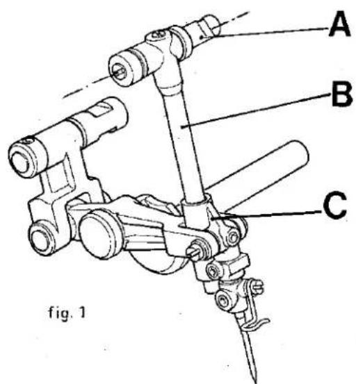
NEEDLE CONTROL MECHANISM (fig. 1)
The needle control mechanism is characterized by the new method of fixing the needle bar to the bed, done with eccentric pin A (fig. 1), the axis of which is set at right angles to the direction of feed.
This fixing method permits needle bar B to follow needle clamp slider C in its run.
The new mechanism has been designed in order to:
— reduce wear on the moving slider of the needle clamp;
— make assembling easier, with more accurate and controllable needle positioning;
- increase the life of the needles, especially very fine ones;
- limit wear on the looper tips.
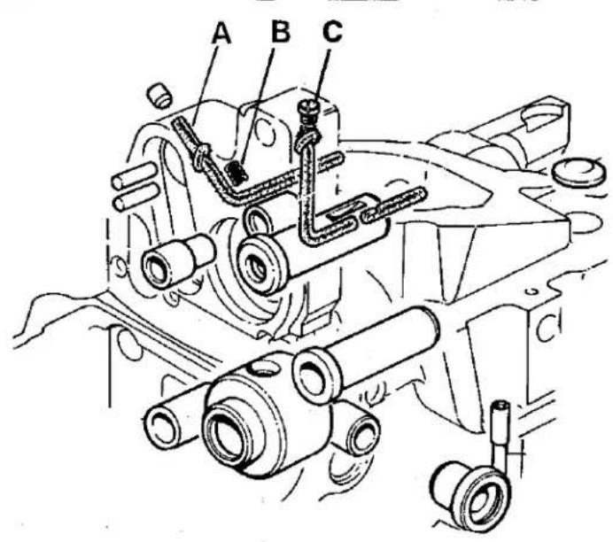
INSTRUCTIONS FOR SETTING ON AND ADJUSTING THE NEEDLE CONTROL MECHANISM (fig. 2)
- Arrange the needle control mechanism assembly (fig. 2) with pins A and B positioned as follows: a) bar support eccentric pin A with milled part turned towards the front of the machine. This positioning serves to orient the eccentricity of the pin towards the top and will permit subsequent insertion of screw C (fig. 3) which, keeping the orientation correct, will limit rotation of the pin to a useful bar-positioning sector.
b) calibrator support pin B with plane C corresponding to screw D (fig. 2).
- Set pins A and B in their respective holes on the machine head, taking care to insert the button of hand control E (fig. 2) at the same time in the hole in lever F. When inserting calibrator pin B (fig. 2), lubricator wick A (fig. 3) must be pulled from the end inside the machine so that the other end is embedded in the spot-facing, pressing spring B (fig. 3) and thus permitting said pin to pass. Releasing wick A (fig. 3) spring B (fig. 3) extends, giving reliable lubrication contact between wicks A and C inside the pin.
- Center locking screws R - G (fig. 2) of the two pins and insert roller retainer H, taking care to choose the correct tolerance value, which should be that indicated on washer L (fig. 2).
| colour | symbol | tolerance |
| R-red | 206517-0-00 | 0.000 |
| -0.002 | ||
| B-blue | 206518-0-00 | -0.002 |
| -0.004 | ||
| G-grey | 208150-0-00 | -0.004 |
| -0.006 |
- Tighten screw M (fig. 2) until it is right down on needle bar eccentric support pin A (fig. 2)
- Set the needle clamp slider to the correct height. When the slider is brought to its lowest position there must be a distance of 35.8 mm. (1:13/32") between the axis of pin Q (fig. 2) and the surface of plate RC908920-0-03 (fig. 2-inset). Adjustment is made by turning screw R (fig. 2).
This setting is the same for all types of machines and must not be altered during subsequent adjusting and timing operations.
Gauge RC908914-0-02 and plate RC908920-0-03 are used as shown in fig. 2 — inset, are a help in obtaining easy and accurate adjustment.
- Center the needle in the needle plate hole. The operation is made accurate and easy by screw M (fig. 2) which, being right up against the pin, offers the possibility of moving it just by screwing.
- Block screw M by fully tightening grub screw N (fig. 2)
- Center the needle clamp slider 0 (fig. 2) in the fork of lever P (fig. 2), dividing play equally, by moving pin B (fig. 2).
- Tighten locking screws D - R (fig. 2).
text_image
A B C fig. 1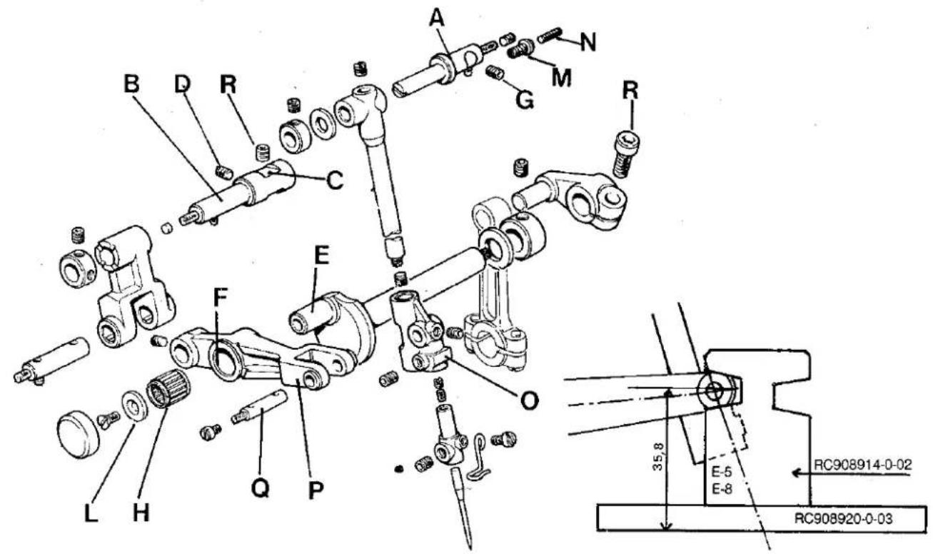
text_image
Technical diagram of mechanical assembly with labeled parts and dimensional annotationsfig.2
text_image
A B Cfig. 3
text_image
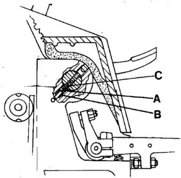
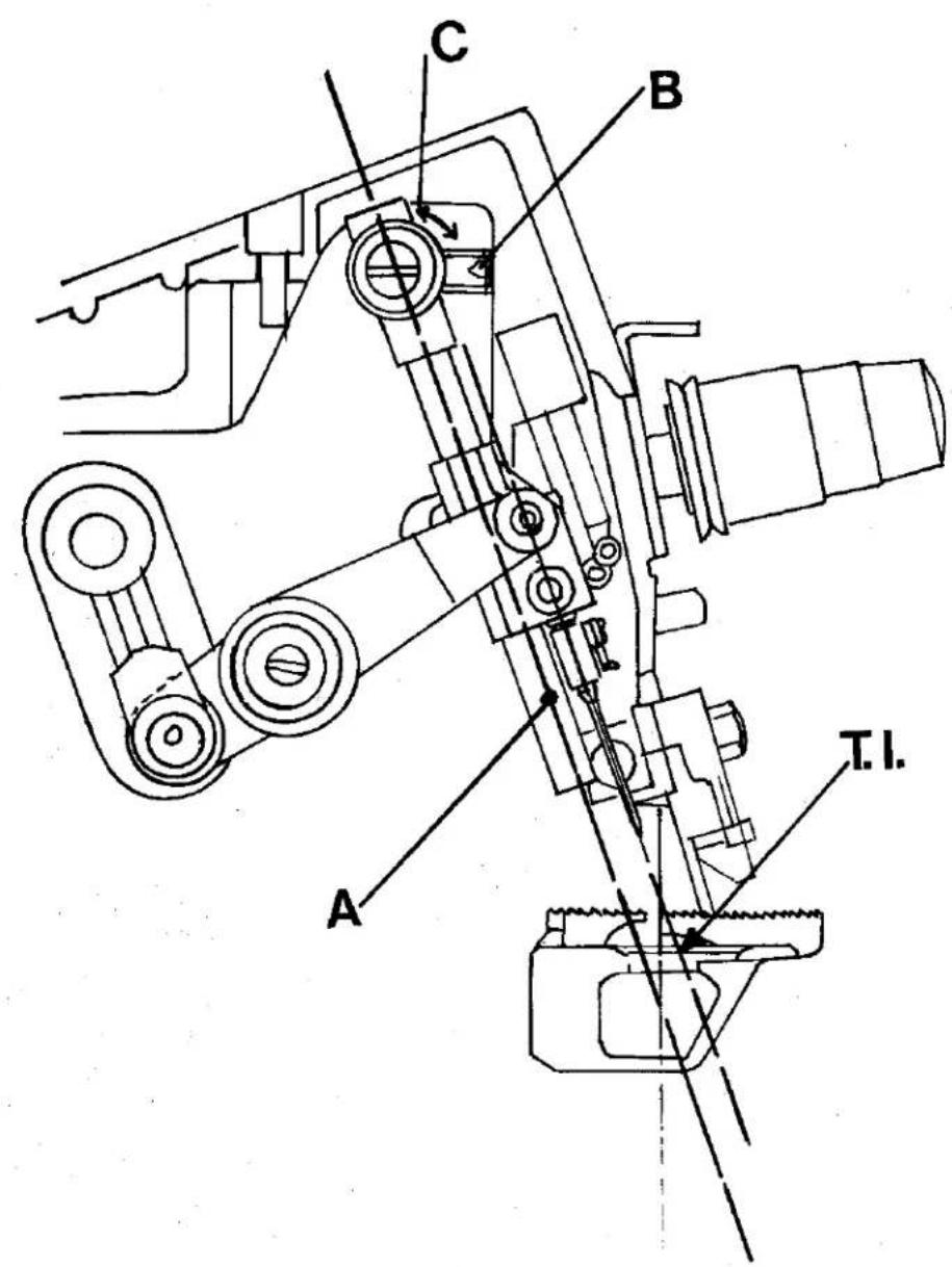
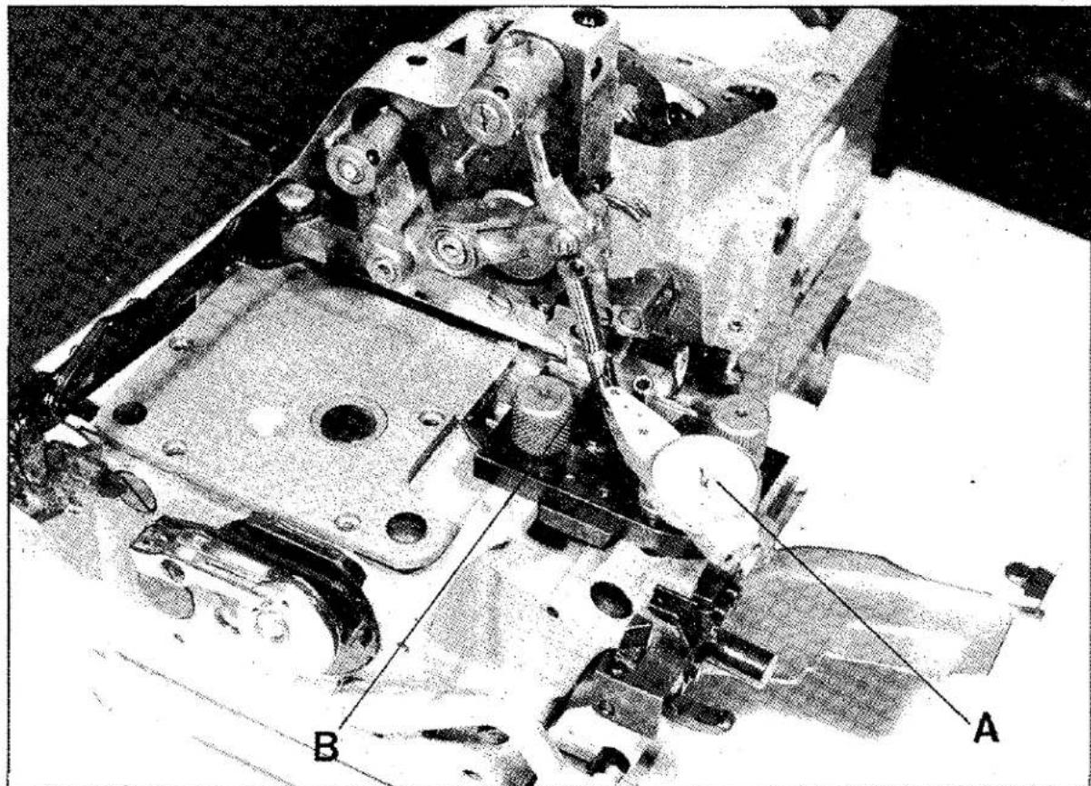
A B CFor aligning needle bar A (fig.4) to the needle movement trajectory T.I. (fig.4) special gauge (RC908920-0-03/RC979550-1-00) with dial comparator A (fig.5) is used, point B (fig.5) of which is positioned on the special extension C (fig.5) screwed to the bottom of the needle bar (see illustration). When the needle clamp slider moves from the bottom dead center point to the top dead center point or viceversa, there should be the least possible vibration of the bar. The amount will vary according to the needle bar stroke: from approx. 0.02 mm. for a short stroke of 24 mm. to 0.04 mm. for a short stroke of 25 mm. (2-needle machine) and medium stroke of 26 mm.
Adjusting and checking is done by turning eccentric pin C (fig.4) in one direction or the other. After making sure that C is right up against screw M (fig.2), lock the pin with its screw B (fig.4).
text_image
A B C T.1.fig.4
text_image
A B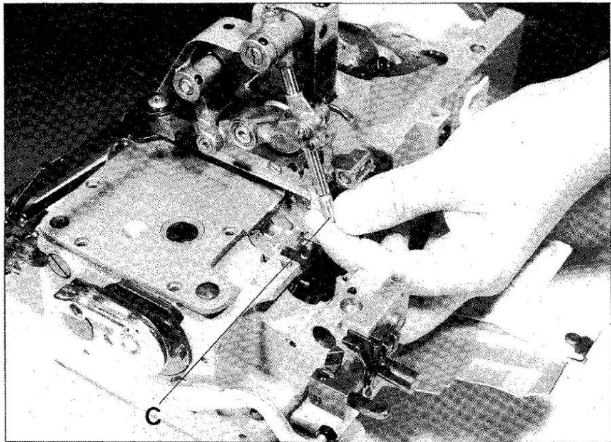
natural_image
Close-up of a hand using a sewing machine to adjust mechanical parts (no visible text or symbols)fig. 5
LUBRICATION SYSTEM (Fig. 6)
A needle valve A (fig. 6) has been introduced in the lubrication system of the new machines for adjusting oil flow to the exact amount necessary for each single subclass to suit operating conditions, speed, work intensity, etc.
The valve has been set in the oil distributor cover plate in which transparent cap B (fig. 6) is incorporated. This cap serves both as an oil circulation control window and oil input plug.
Instructions for adjusting the regulator valve
The valve can be adjusted, with the machine assembled and working, by removing the screw on the tension-holder cover. Adjustment is carried out by unscrewing nut C (fig. 6) that locks the screw. When screw D (fig. 6) is turned in the clockwise direction it is brought to the end of its run in the closed position.
From this position the screw must be turned counter-clockwise to increase the oil flow. The flow can be checked through the oil window on the cover under the work plate.
Even when the valve is in the fully closed position, enough oil to prevent seizing continues to circulate.
FRONT AND REAR NEEDLE GUARDS (fig. 7)
Front and rear needle guards of new design have been introduced on the new E-5 Class machines. Their main feature is that, when the needle size is changed, they can be brought closer to or moved further away from the needles while maintaining their planes parallel to the needles.
Further, they can also be adjusted in height and, on 2-needle machines, they can turn on the axis of the shank fixing them to the supporting collar.
These features permit correct positioning to be obtained in any case, thus ensuring perfect protection for the needles and consequently limiting wear on the looper tips.
Instructions for adjusting and positioning the needle guards
The rear needle guard supporting block A (fig. 7) is fixed to the bed with two screws B (fig. 7). There is pin C (fig. 7) on the block where brackets or clamps of the front and rear needle guards D (fig. 7) will be fixed. This support method offers the possibility of moving the front and rear needle guards closer together or further apart without changing the parallel positioning of their surfaces with the needles. To adjust them one only has to slacken the clamp collar screws E (fig. 7) and move the two clamp collars on the supporting shaft.
The operation is facilitated by a rear block F (fig. 7) that acts as a stop to the clamp collars, so that their screws can be turned easily.
Adjusting the rear needle guard
The adjusting procedure differs for 1-needle and 2-needle machines.
a) 1-needle machines
The rear needle guard for single-needle machines has a flat surface on the shank which enables it to oriented correctly. For making the adjustment in height, the needle must be brought to the bottom dead center position and, referring to the rear needle guard bevel and the needle eye, the former is adjusted in height to obtain the bottom of the eye in line with the bevel (see fig. X). To ensure that it is correctly adjusted, thread the needle and check that the thread passes freely through the eye when the needle is the bottom dead center position.
b) 2-needle machines
For 2-needle machines the height adjustment is made as for single-needle machines. The only difference is that there is no orienting and fixing plane on the shank.
This offers the possibility of orienting the rear needle guard so that the needles are correctly positioned in relation to the two internal planes. (see Fig. 2) Tighten the locking screw, taking care not to alter the height setting.
Adjusting front needle guard
For making the height adjustment the front needle guard is positioned according to the thickness of the needle plate, as follows:
- 3 mm. thick needle plate: plane Y (fig. W) must be positioned close against clamp collar B
- 4.25 mm. thick needle plate: plane Y (fig. W) must be positioned at 1.3 mm. from plane B.
For adjusting direction, proceed as for the rear needle guard.

text_image
A B C D fig. 6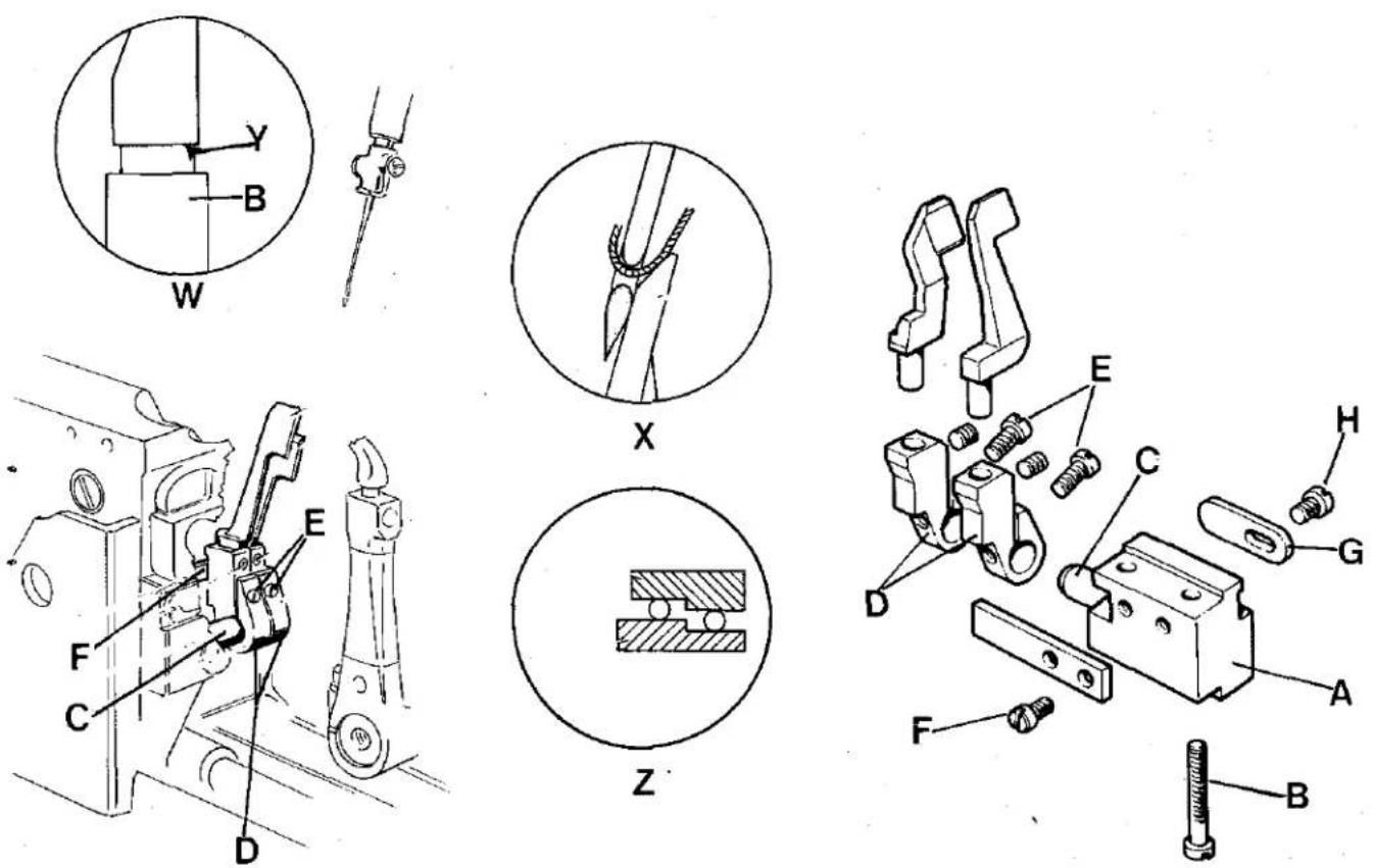
fig. 7
OIL SEAL SYSTEM ON FEED DOG SLIDERS
In order to improve the oil seal on feed dog sliders E (fig. 8) a new oil seal system has been designed, which consists of two new gaskets A (fig. 8), made of a special rubber compound, with oil scraper lip and a new guide system B (fig. 8). Further, the slider section has been modified by rounding the outside corners so that the gaskets last longer.
With this new system it is also easier to replace the gaskets. All that has to be done is disassemble the needle plate, feed dogs, loopers, rear needle guard and the feed mechanism cover plate C (fig. 8) looper bracket for E-8 and remove the slider guide D (fig. 8) in order to reach the two gaskets and disassemble them.
NEEDLE BAR MECHANISM COVER PLATE (Fig. 9)
The new needle bar mechanism cover plate also incorporates the presser foot assembly. So only the top tension-holder cover plate A (fig. 9) has to be removed and the two locking screws B (fig. 9) unscrewed to reach the needle bar mechanism, thus cleaning of the needle bar mechanism and relative maintenance operations are very much easier.
Also, an L-shaped gasket C (fig. 9) has been fitted around the bottom edge of the cover plate, touching the bed, to ensure a perfect oil seal and so prevent leakage on to the work plate where the fabric moves along.
OIL SUMP (Fig. 10)
The new sump containing lubricating oil has a vertical channel all round its perimeter for collecting any oil sweating that may occur on the walls. A special screw B (fig.10) is provided for draining off any oil that may accumulate.
Another important feature is the method of connecting bed and sump, which is done by means of five screws, accessible from above once the top cover plate has been removed and the work plate opened. Connected in this way, there is easy access to the internal components of the machine without removing the oil-filled sump from the unit stand during maintenance and conversion operations.

text_image
C B D A E A B E c fig. 8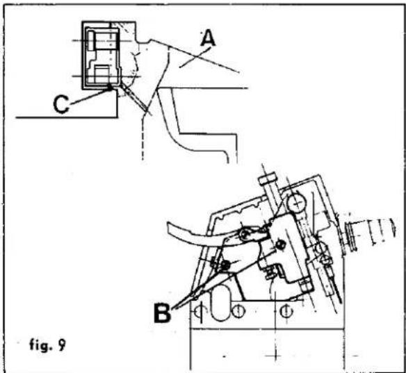
text_image
A C B fig. 9
text_image
A B fig.10A new pivotal system has been introduced on the work plate (fig. 11). Connected with the machine bed and anchored to it, is a new device that, through lever A (fig. 11) situated on the machine, permits the work plate to be uncoupled. The rubber pads B (fig. 11) on the feed mechanism cover plate are for damping plate vibrations, thus considerably reducing noise when the machine is working. For this purpose the distance between the work plate C and cover M (fig. 11) of the feed mechanisms has been increased by 0.5 mm.
ADJUSTING INSTRUCTIONS
For adjusting plate rotation the two cup springs D (fig. 11) must be set so that they brake the rotation to a greater or lesser extent. To obtain the correct setting turn nut E (fig. 11) on pivot so that the springs are compressed to a greater or lesser degree, making sure that they are not flattened completely, then lock counter-nut F (fig. 11).
The uncoupling device must be positioned so that there is always about 0.2 mm. between the work plate and the edge of the needle plate and so that there is no 'step' between the surface of the needle plate and that of the work plate.
To adjust this position, the uncoupling block is fixed to the machine head by two screws G (fig. 11) set in a slot, which permits it to be brought closer to the edge of the needle plate.
Block H (fig. 11) acts as a stop to the hook, so it must be resting on the latter after the work plate has been closed and adjusted.
Lever L (fig. 11) acts on the top part of the hook so that closing it forces it downwards to a greater or lesser extent, thus ensuring contact with the rubber pads and accurate adjustment in height in relation to the needle plate.

text_image
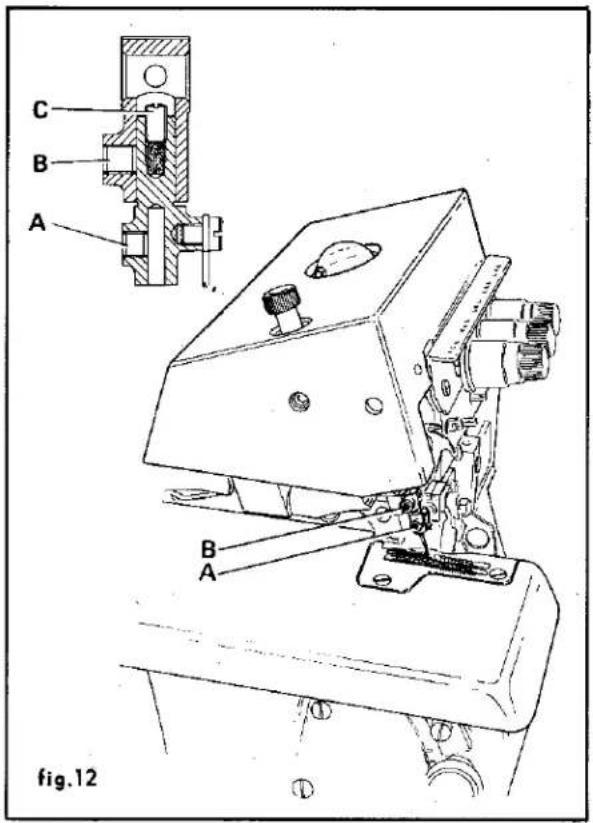
D E F M B L C A H G fig.11SETTING ON AND ADJUSTING NEEDLE CLAMP (Fig. 12)
- Insert the needle down inside the clamp and fasten it with screw A (fig. 12)
- Set the clamp on slider B (fig. 12), taking care to position the needle with the scarf facing inwards on the machine
- Position the needle height as specified in the setting table.
To make the adjustment in height, proceed as follows:
— Slacken screw B (fig. 12) and take off the clamp
— Turn adjusting screw C (fig. 12) which acts as stop to the clamp in the slider seat, tightening it to increase the needle height and slackening to decrease the height.
— Bear in mind that one full turn of the screw C corresponds to a height difference of 0.45 mm.
In addition to simplifying the setting operation, this system offers the possibility of disassembling the clamp for any maintenance or conversion operations and for better orientation of the needles in relation to loopers and needle guards in machines with several needles.
text_image
C B A B A fig.12E-8 Class safety stitch machines have the same characteristics as those described so far, except for the front and rear needle guards. Further they are not designed for being fitted with containers for moistening the needle points and eyes.
The element that most characterizes this Class is the new chainstitch looper control mechanism with the chainstitch looper elliptical movement derived directly from inside the base.
The new mechanism has been designed in order to: Improve lubrication of the moving mechanical parts and, at the same time, protect them from dust and fluff, thus making the mechanism—and consequently the looper movement—more reliable.
Facilitate the timing operation, since the chainstitch looper movement is separate from the overedge stitch bottom looper movement. A flat surface on the looper shank determines the looper slant, to which it is possible to make a small correction.
Facilitate the threading operation. Only a button needs to be pressed, when the needles are in the bottom dead center position, to uncouple the looper which, turning towards the outside of the machine, permits quick and easy threading of the two holes in the looper. Recoupling is automatic when the looper is pushed lightly forward.
Ensure the best stitch formation with the introduction of a new shaped looper, designed for ensuring the best conditions for formation of the chainstitch (entering the loop and entering the triangle formed by the looper thread and the needle loop) and with a looper thread control cam with larger profile for continuous control of the looper thread. The needles used are the same for both the chainstitch and the overedge stitch; they are 3029 GS needles which have the scarf designed specially to ensure that the loop is taken up perfectly on both stitches.

natural_image
Technical line drawing of a mechanical assembly with gears and linkages (no text or symbols)INSTRUCTIONS FOR DISASSEMBLING, RE- ASSEMBLING AND ADJUSTING THE CHAIN- STITCH LOOPER CONTROL MECHANISM
Disassembly
— Take off the cover plates and the work plate
- Remove the sewing parts: needle plate, cutters, feed dogs, rear and front needle guards
— Disassemble looper bracket 1 (fig. 1) by unscrewing screw 2 (fig. 1)
- Disassemble thread guide assembly 1 (fig. 2) by slackening screws 2 (fig. 2), thread take-up cam 3 (fig. 2) and supporting flange 4 (fig. 2)
- Disassemble the big-end of connecting-rod 3 (fig. 1)
- Slacken Allen screw 4 and screws 5, remove screw 6 (fig.1)
- Take off shaft 7 (fig. 1)
— Disassemble big-end of con-rod 8 (fig. 1)
— Disassemble counter feed shaft 5 (fig. 2) after un-
screwing screws 6, 7 and 8, then remove arm of handle 9, differential handle 10 and differential sector 11 (fig. 2)
- Disassemble stitch regulator eccentric-cam assembly 12 (fig. 2) bringing the point to "0" and removing screw 13 and screws 14 (fig. 2)
- Take off con-rod 15 (fig. 2)
— Remove spring 16 and take off cam 17 (fig. 2)
— Take off cam 18 (fig. 2) after unscrewing relative screws 19 (fig. 2)
— Unscrew ring screws 9 (fig. 1)
— Slacken screws of retainer 10 (fig. 1) set in the base at the end of pin 11 (fig. 1) - Remove snap ring 12 (fig. 1) and take out pin 11
— Disassemble lever 13 (fig. 1) removing screw 14 and taking out pin 15
— Take off con-rod 16 (fig. 1) levering on the machine handwheel and springing the shaft outwards; this is the only way to disassemble said con-rod.

text_image
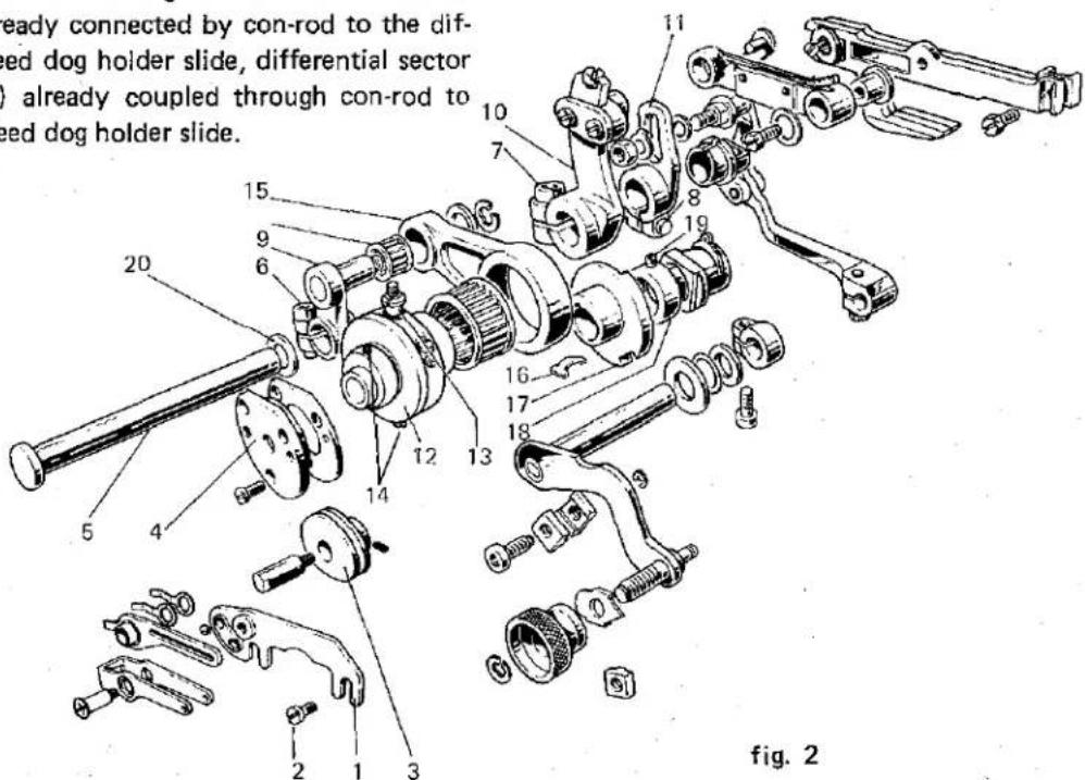
Exploded view diagram of a mechanical assembly with numbered parts for identificationfig. 1
Assembly
-- Insert con-rod 21 (fig. 1), levering on the machine handwheel and springing the shaft outwards Make sure that the setting notch on the con-rod is facing towards the outside of the machine
- Set on looper-ellipse cam 18 and lightly lock screws 19 (fig. 2)
- Assemble lever 13 (fig. 1) to the con-rod by inserting pin 15 (fig. 1), take care to insert it with the internal wick plug screw towards the outside of the machine and the notch turned towards the hole for screw 14 (fig. 1)
— Insert pin 11 (fig. 1), setting the following parts on it in this order: ring 9, washer 16, lever 13, washer 17 and snap ring 12 which is fitted with the special clamp in the collar on the shaft
- Bring ring 9 (fig. 1) close up, thus packing lever 13 (fig. 1)
- Set on cross-piece 18 (fig. 1) and provisionally insert looper-holder shaft 7, centering it in the hole in the cross-piece, moving pin 11 (fig. 1) axially, then lock it with screws 10 situated at its extremities. There is a locking plane on the outer extremity where the relative screw is tightened.
- Assemble the feed cam assembly in the following order: cam 17 (fig. 2), spring 16, con-rod 15, stitch regulator cam assembly with roller cage inserted.
- Tighten screw 14 in the notch on the main shaft, then tighten Allen screw 14 (fig.2)
- Assemble feed counter-shaft, setting on the parts in the following order: washer 20, handle arm 9 (fig. 2) with its bearing inserted in con-rod 15 (fig. 2) already connected by con-rod to the differential feed dog holder slide, differential sector 11 (fig. 2) already coupled through con-rod to the main feed dog holder slide.
- Tighten Allen screw 6 (fig. 2) right up against the bushing in the base
- Tighten screws 7 and 8 fixing the differential hand adjuster and differential sector, and position
- Set on the looper control con-rod 8 (fig. 1)
- Next insert the looper movement shaft 7 (fig. 1) and afterwards set on the parts in this order: looper uncoupling assembly 19 (fig. 1), ring 20, crosspiece 18, washer 23, ring 22 (fig.1)
- Insert screw 6 (fig. 1) in the notch on the shaft and tighten it.
Bring ring 22 (fig. 1) up close and lock screws 5 (fig. 1). This sets the axial position of the shaft.
- Bring the looper uncoupling assembly close up to ring 20 (fig. 1) and tighten Allen screw 4 (fig. 1)
Insert the sphere in con-rod 8 (fig. 1) and assemble the con-rod big end 3 (fig. 1) - Set on flange 4, take-up cam 3 and thread guide assembly 2 (fig. 1)
- Time the looper ellipse movement cam 18 (fig. 2), bringing the needle clamp slide to the bottom dead center position. The two reference notches, one on the cam and one on the relative con-rod must coincide.
- Continue with the setting operation according to the setting chart, remembering that the looper slant is given by the flat surface on the looper shank which will give a certain possibility of rotation, so that the slant can be adjusted better to suit setting requirements
- Complete assembling of all sewing parts and cover plates.
text_image
ready connected by con-rod to the dif- peed dog holder slide, differential sector ) already coupled through con-rod to peed dog holder slide. 15 9 6 20 14 13 12 17 16 18 10 7 8 19 5 4 2 1 3 fig. 2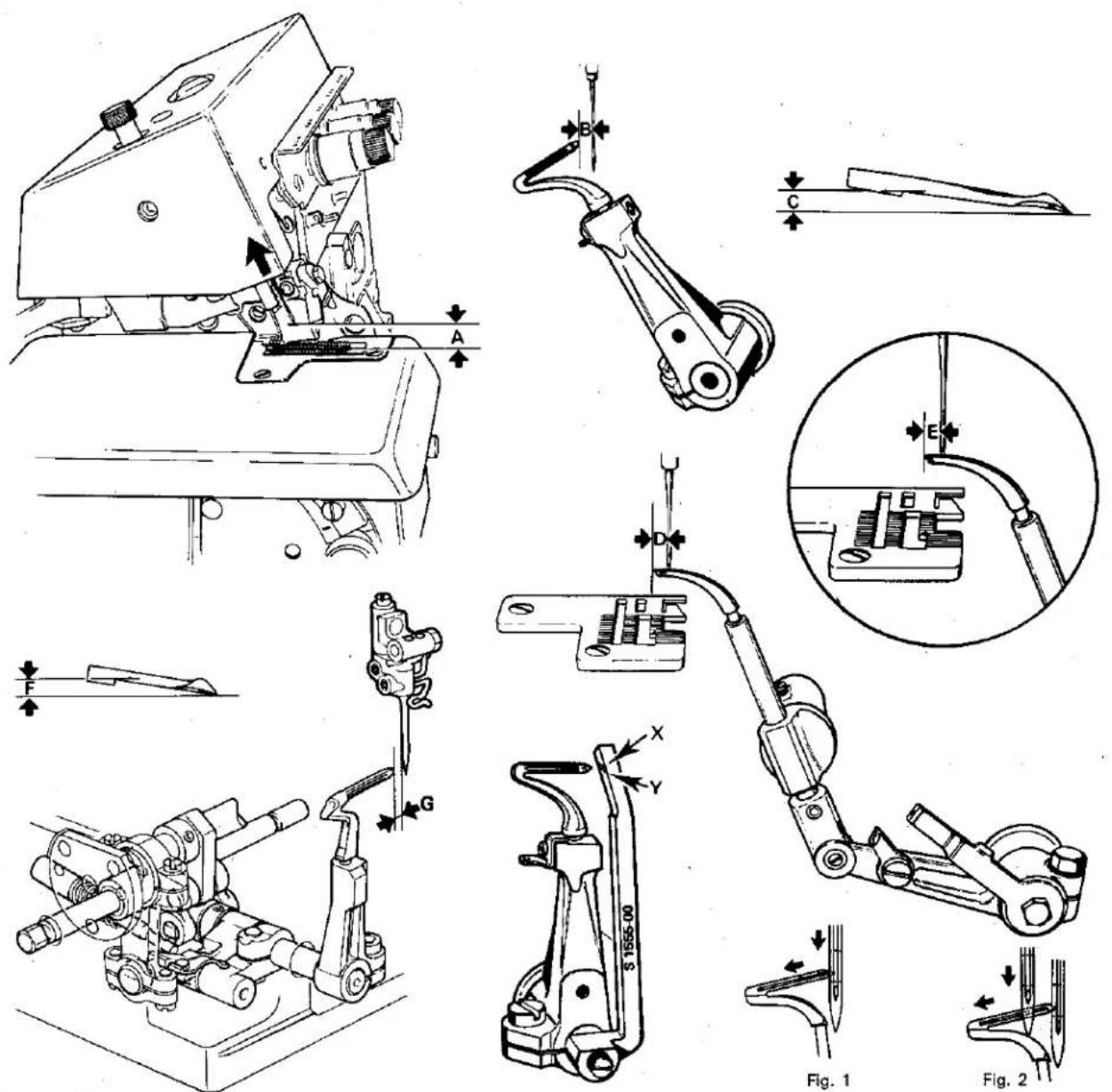
| MACHINE CLASSES | A | B | C | D | E | F | G | ||||
| E80001-DM2 | E80001-SM2 | X | 9,8÷10,1 | 1,5~ | 2÷2,6 | 4,8÷5,1 | 5÷5,2 | 1,3÷1,6 | 1,2÷1,5 | C | Fig. 1 |
| E80006-DM2 | E80002-SM2 | ||||||||||
| E80007-DM2 | E80003-SM2 | ||||||||||
| E80010-DM2 | E80007-SM2 | ||||||||||
| E80013-DM2 | E82204-DM2 | ||||||||||
| E80017-DM2 | E82304-DM2 | ||||||||||
| E80019-DM2 | E84901-DM2 | ||||||||||
| E80023-DM2 | |||||||||||
| E80003-DC2 | E80011-DC2 | X | 8÷8,4 | 1,5~ | 2,3÷2,5 | 3,4÷3,6 | 3,7÷4 | 1,3÷1,8 | 1~ | - | Fig. 1 |
| E80004-DC2 | E82202-DC2 | ||||||||||
| E80009-DC2 | E82302-DC2 | ||||||||||
| E80001-DC2 | E80004-SC2 | X | 8÷8,4 | 1,5~ | 2,3÷2,5 | 3,4÷3,6 | 3,7÷4 | 1,3÷1,8 | 1,2÷1,5 | - | Fig. 1 |
| E80005-DC2 | E80005-SC2 | ||||||||||
| E80008-DC2 | E80006-SC2 | ||||||||||
| E80012-DC2 | E81202-DC2 | ||||||||||
| E80015-DC2 | E82203-DC2 | ||||||||||
| E80022-DC2 | E82303-DC2 | ||||||||||
| E80020-DM3 | X | 8,7~ | 1,5~ | 2,3÷2,7 | 8,5~ | 2~ | 1,2÷1,5 | A | Fig. 2 | ||
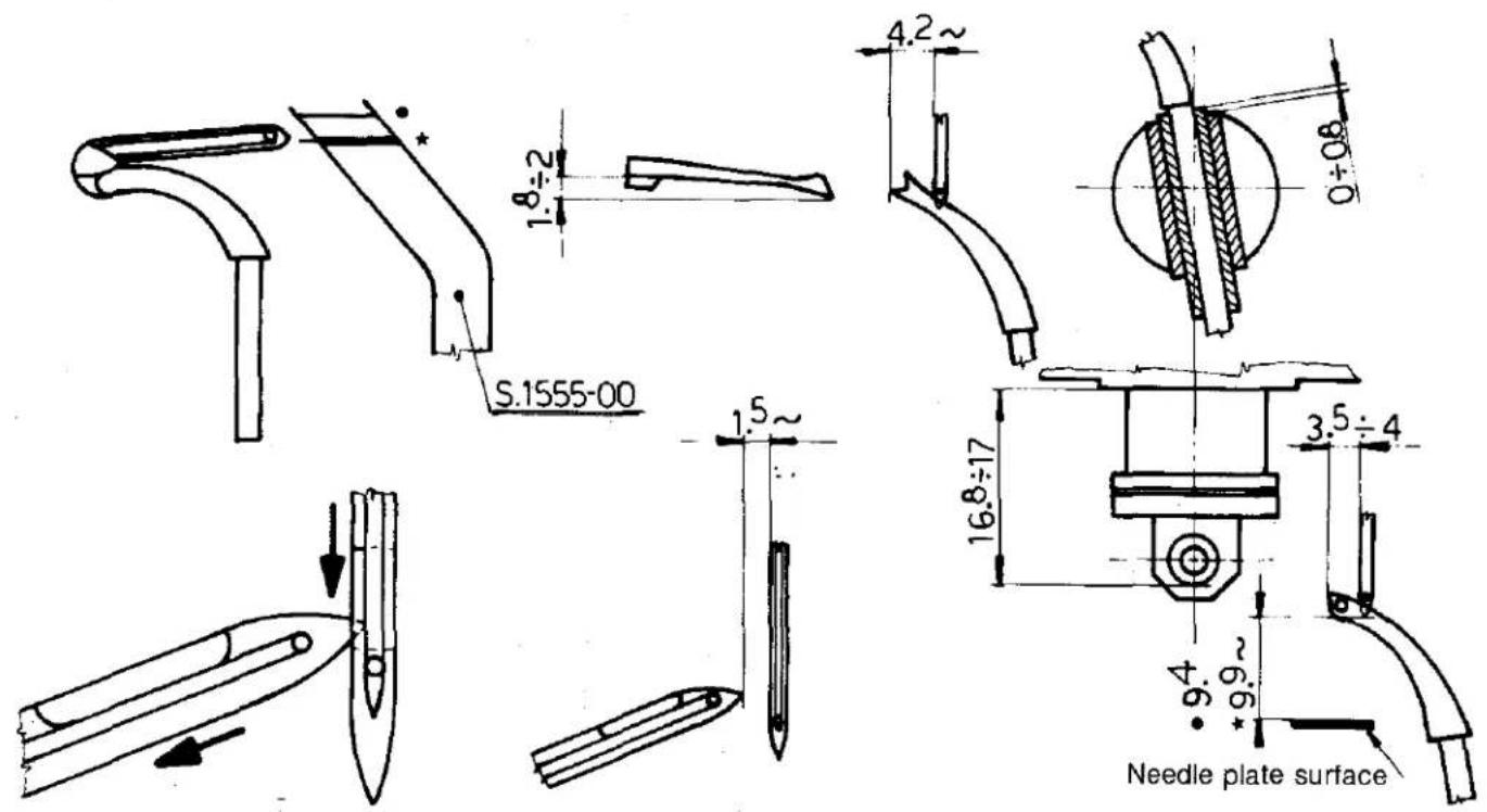
text_image
S.1555-00 1.8÷2 4.2~ 1.5~ 16.8÷17 3.5÷4 9.4 9.9~ Needle plate surface★ E50007-DC1/203-97
★ E50001-DC1/203-97
★ E50002-DC1/203-97
E50030-DC1/203-97
★ E50031-DC1/203-97
Ensure that the needle touches the front and rear needle guards when the point of the primary looper enters the needle groove.
Please Note; By pushing the needle at its lowest point against the needle guard, the thread should run free.
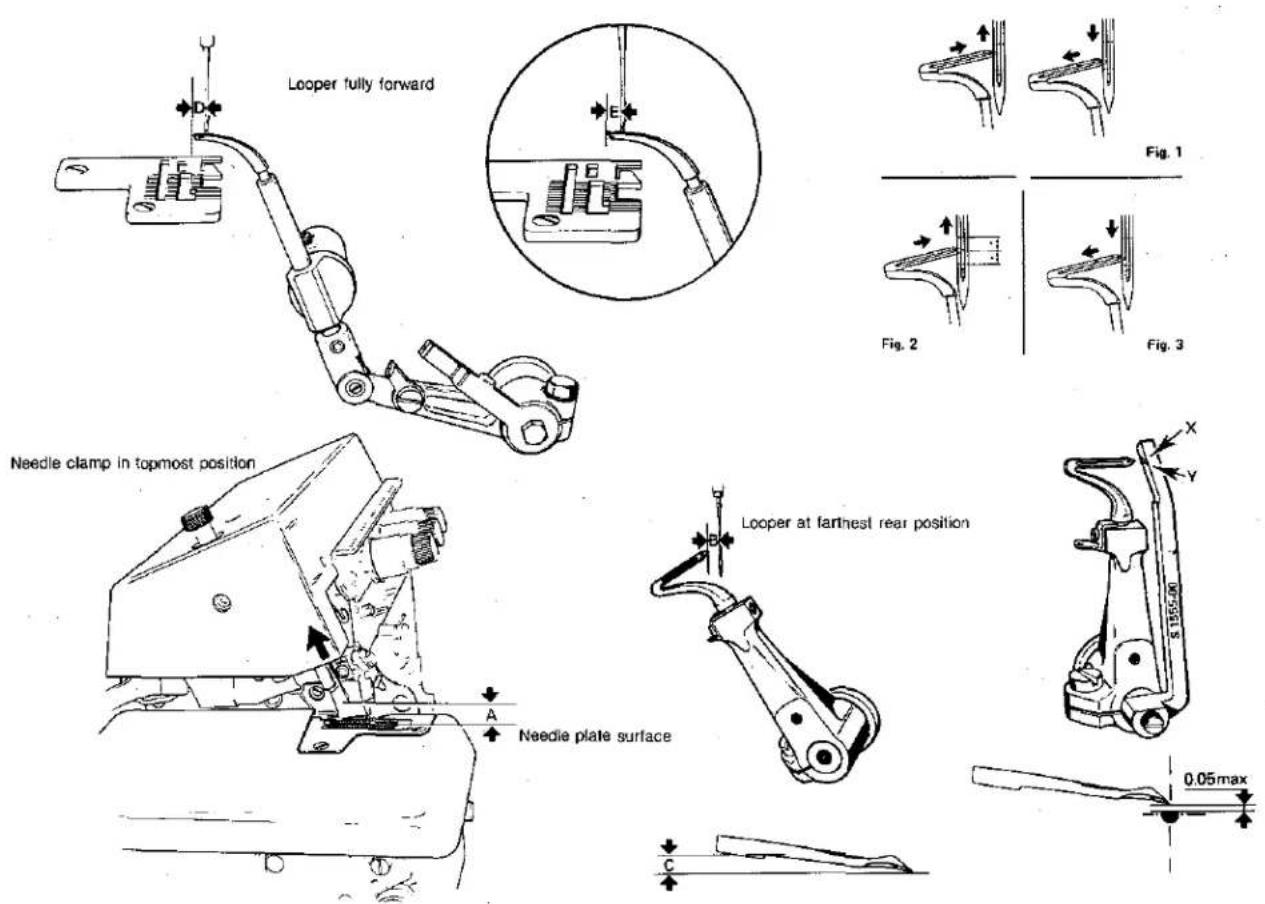
text_image
Looper fully forward Needle clamp in topmost position A Needle plate surface E Fg. 1 Fig. 2 Fig. 3 Loooper at farthest rear position 0.05max| MACHINE CLASSES | A | B | C | D | E | F | G | H | ||||
| E50001-DC1 E50003-DC1 | E52813-DC1 | X | 10~ | 1.5~ | 2,3÷2,5 | 3,6÷4 | 4,2~ | - | - | - | - | Fig. 1 |
| E50001-DC1 E50002-DC1 E50007-DC1 E50025-DC1 E50026-DC1 E50029-DC1 E50031-DC1 E50101-DC1 E50102-DC1 E50104-DC1 E50105-DC1 E51002-DC1 E51006-DC1 E50109-DC1 | E50601-DC1 E52202-DC1 E52203-DC1 E52204-DC1 E52302-DC1 E52802-DC1 E52803-DC1 E52901-DC1 E52902-DC1 E52905-DC1 E52906-DC1 E53401-DC1 E53402-DT1 E540C1-SC1 | Y | 9.9~ | 1.5~ | 2,3÷2,7 | 3,5÷4 | 4.2~ | - | - | - | - | Fig. 3 |
| E50020-DC1 | E50138-DC1 | Y | 9.9~ | 1.5~ | 2,3÷2,7 | 3,5÷4 | 4.2~ | - | - | - | - | Fig. 3 |
| E50006-DC1 E50030-DC1 E50103-DC1 | E52201-DC1 E52301-DC1 | X | 9.4~ | 1.5~ | 2,3÷2,7 | 3,5÷4 | 4.2~ | - | - | - | - | Fig. 3 |
| E52804-UC1 | E52806-UC1 | X | 9.1~ | 2.5~ | 2,5÷2,8 | 3,7÷4 | 4~ | - | - | - | - | Fig. 3 |
| E50001-DC1/203-97 E50007-DC1/203-97 | Y | 9.9~ | 1.5~ | 1,8÷2 | 3,6÷4 | 4.2~ | - | - | - | - | Fig. 3 | |
| E50005-DC1 E50009-DC1 E50039-DC1 E50005-DC1/203-97 | E52807-DC1 E52812-DC1 | Y | 9.9~ | 1.5~ | 2.3~ | 5~ | - | - | - | - | - | Fig. 3 |
| E50010-DC1 | Y | 9.9~ | 1.5~ | 2.3~ | - | 5~ | - | - | - | - | Fig. 3 | |
| E50023-DC1 E50034-DC1 | E50010-SC1 | X | 10.2~ | 3~ | 2,6÷3 | 4~ | - | - | - | - | A | Fig. 2 |
| E53007-DC1 | Y | 11.2~ | 1~ | 2,3÷2,6 | 8~ | - | - | - | - | A | Fig. 3 | |
| E50023-DM1 E50033-DM1 E50108-DM1 E52207-DM1 | E52812-DM1 E53402-DM1 E53403-DM1 | X | 10.7~ | 2.5~ | 2,5÷3 | 5÷5,1 | 5~ | - | - | - | B | Fig. 3 |
| E54901-DM1 | X | 10.7~ | 2.5~ | 2,5÷3 | 4.4~ | 5~ | - | - | - | C | Fig. 3 | |
| E50050-DC1 | X | 10.5~ | 4.5~ | 2,6÷3 | 4.2~ | - | - | - | - | - | Fig. 2 | |

| MACHINE CLASSES | A | B | C | D | E | F | G | H | ||||
| E50020-DM2 | E50003-SM2 | X | 9,9~ | 1,5~ | 2,3 ÷ 2,7 | 8,5~ | - | - | - | - | A | Fig. 1 |
| E50036-DM2 | E50107-DM2 | |||||||||||
| E50001-SM2 | E50111-DM2 | |||||||||||
| E50002-SM2 | ||||||||||||
| E50021-DM2 | X | 9,9~ | 1,5~ | 2,3 ÷ 2,7 | 3,3 ÷ 3,5 | - | - | - | - | B | Fig. 1 | |
| E50012-DC2 | E50047-DC2 | Y | 9~ | 3,7 ÷ 3,9 | 2,3 ÷ 2,5 | 3,5 ÷ 3,7 | 3,5 ÷ 3,7 | - | - | - | - | Fig. 2 |
| E50013-DC2 | ||||||||||||
| E50018-DC2 | E50105-DC2 | X | 9,8~ | 1,5~ | 2,3 ÷ 2,4 | 2,7 ÷ 2,9 | - | - | - | - | 8 | Fig. 1 |
| E50041-DC2 | E50002-SC2 | X | 9÷9,5 | 1,5~ | 1,8 ÷ 2 | 6,1 ÷ 6,4 | - | - | - | - | A | Fig. 1 |
| E50001-SC2 | ||||||||||||
| E50014-DC2 | E50032-DC2 | X | 9,4~ | 1,5~ | 2,3 ÷ 2,5 | 3,1 ÷ 3,5 | - | - | - | - | - | Fig. 1 |
| E50015-DC2 | E50045-DC2 | |||||||||||
| E50016-DC2 | E50105-DC2 | |||||||||||
| E50017-DC2 | E52206-DC2 | |||||||||||
| E50038-DC2 | X | 9,4~ | 1,5~ | 2,2 ÷ 2,4 | 4 ÷ 4,5 | 4 ÷ 4,5 | - | - | - | A | Fig. 3 | |
| E50044-DC2 | X | 9,7~ | 3~ | 2,5 ÷ 3 | 3~ | 3~ | - | - | - | A | Fig. 4 | |
| E50120-DC2 | X | 9~ | 1,5~ | 2,3 ÷ 2,4 | 6,5 | - | - | - | - | - | Fig. 1 | |
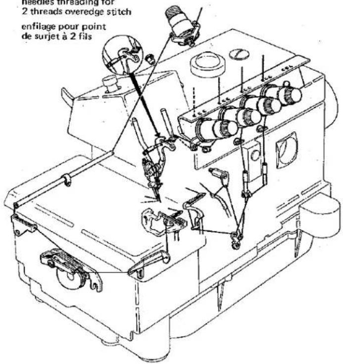
INFILATURA - ENFILAGE - THREADING - EINFÄDELUNG - ENHEBRADO - BAEBAHNE HITÉЙ
needles threading for
2 threads overedge stitch
enfilage pour point
de surjet à 2 fils
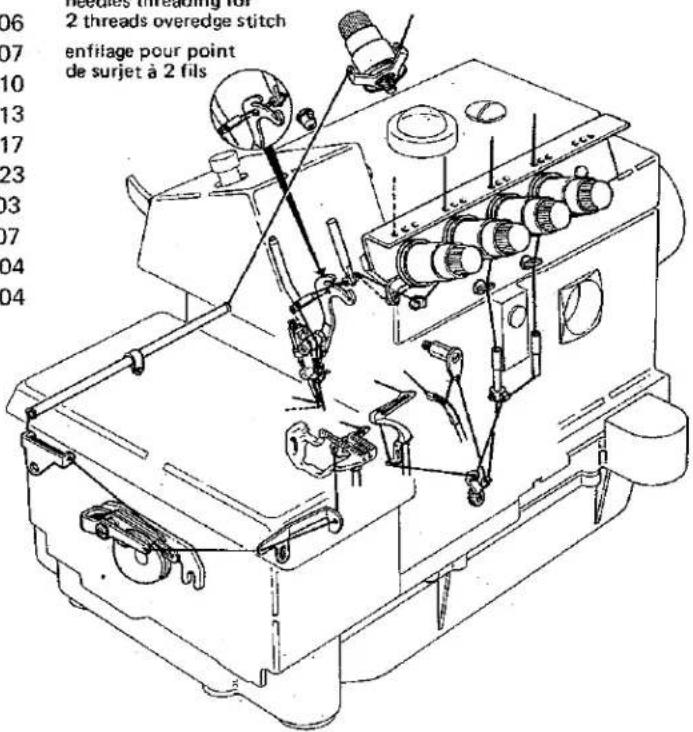
needles threading for
2 threads overedge stitch
enfilage pour point
de surjet à 2 fils
529-00-2CD-01
529-00-2CD-03
529-00-2CD-04
529-00-2CD-05
529-00-2CD-08
529-00-2CD-09
529-00-2CD-11
529-00-2CD-12
529-00-2CD-15
529-00-2CD-22
529-00-2CS-06
529-12-2CD-02
529-22-2CD-02
529-22-2CD-03
529-23-2CD-02
529-23-2CD-03
natural_image
World map of the Americas and surrounding oceans and equatorial regions, showing continents and latitude/longitude lines (no text labels)WORLDWIDE SALES AND SERVICE
Union Special Corporation maintains sales and service facilities throughout the world. These offices will aid you in the selection of the right sewing equipment for your particular operation. Union Special Corporation representatives and servicemen are factory trained and are able to serve your needs promptly and efficiently. Whatever your location, there is a Union Special Corporation representative to serve you. Check with him today.
It is important to remember that LEWIS® and COLUMBIA® machines are also products of Union Special Corporation, thus offering the industry the most complete line of the Finest Quality sewing machines.
Norcross, GA
Chicago, IL
Dallas, TX
Commerce, CA
New York, NY
Philadelphia, PA
Woburn, MA
Opa-Locka, FL
Montreal, Quebec
Toronto, Ontario
Catano, Puerto Rico
Brussels, Belgium
Leicester, England
Paris, France
Stuttgart, W. Germany
Hong Kong
Other Representatives throughout
all parts of the world
Union Special® Industrial Sewing Equipment
Union Special Corporation, 400 N. Franklin Street, Chicago, IL 60610, U.S.A. Union Special, GmbH, Schwabstrasse 33. D-7000 Stuttgart 1. West Germany.