56500U - Sewing machine Union Special - Free user manual and instructions
Find the device manual for free 56500U Union Special in PDF.

User questions about 56500U Union Special
0 question about this device. Answer the ones you know or ask your own.
Ask a new question about this device
Download the instructions for your Sewing machine in PDF format for free! Find your manual 56500U - Union Special and take your electronic device back in hand. On this page are published all the documents necessary for the use of your device. 56500U by Union Special.
USER MANUAL 56500U Union Special
STYLES ADJUSTING INSTRUCTIONS AND ILLUSTRATED PARTS LIST
SERIES 50000 - ADVANCED, HIGH SPEED, FLAT BED MACHINES.
CATALOG
NO. 129M-GR
FIRST EDITION
© 2006
PRINTED 2006 IN USA
INFORMATION SUBJECT TO CHANGE WITHOUT NOTICE
© UNION SPECIAL CORPORATION ALL RIGHTS RESERVED IN ALL COUNTRIES.
IDENTIFICATION OF MACHINES
Each UNION SPECIAL machine carries a Style number, which on these Classes of machines, is stamped into the style plate affixed to the right front of machine.
The serial number is stamped in the casting at the right rear base of machine.
CLASS DESCRIPTION (56200)
Advanced high speed, low or medium throw, flat bed machines. Single needle, one looper, enclosed automatic lubricating system. Maximum recommended speed 6500 R.P.M. Maximum work space to right of needle bar 8 1/4 inches (209.6mm).
MACHINE STYLES
56200 H Low throw machine. Typical application - For miscellaneous seaming operations on light to medium weight wash and wear materials where chaining and a short stitch are required. Seam specification 401 SSa-1. Type 101 GS needle.
56200 K Low throw machine. Typical application - For binding aprons and dresses made with light to medium weight materials. Seam specification 401 BSc-1. Type 106 GLS needle. Uses cut edge binding 3/4, 7/8, 1, 1 1/8, 1 1/4 inch (19.0, 22.2, 25.4, 28.6, 31.8mm) wide and produces a 7/32, 1/4, 9/32, 11/32, 13/32 inch (5.6, 6.4, 7.1, 8.7, 10.3mm) finish, respectively.
56200 L Medium throw machine. Typical application - For binding mattress ticks made with medium to medium heavy weight materials. Seam specification 401 BSa-1. Type 126 GS needle. Uses selvage edge binding 5/8, 3/4, 7/8 inch (15.9, 19.0, 22.2mm) wide and produces a 5/16, 3/8, 7/16 inch (7.9, 9.5, 11.1mm) finish, respectively.
*56200 R Low throw machine. Typical application - For joining shoulders of shirts in one operation made with light to medium weight materials. Seam specification 401 LSe-1. Type 106 GLS needle.
56200 S Low throw machine. Typical application - For miscellaneous operations on woven materials, knitted drawer bands, knitted shirt fronts made with light to medium weight materials. Seam specification 401 SSa-1. Type 108 GHS needle.
56200 W Medium throw machine. Typical application - For seaming cotton flannel and leather palm gloves. Seam specification 401 SSa-1. Type 128 GAS needle.
CLASS DESCRIPTION (56300)
Advanced high speed, medium or high throw, flat bed machines. Single needle, one looper, enclosed automatic lubricating system. Maximum work space to right of needle bar 8 1/4 inches (209.6mm).
Discontinued - Replaced by Style 56300 M.
*Discontinued - In most instances, replacement parts are available.
CLASS DESCRIPTION (56300 Continued)
MACHINE STYLES
56300 E Medium throw machine, equipped with thumbscrew adjustable frame needle thread eyelet, automatic chain cutter and pressure release attachment. Typical application - For seaming trousers and coats made with medium to medium heavy weight materials. Seam specification 401 SSa-1. Type 128 GBS needle. Maximum recommended speed 6500 R.P.M.
56300 F Medium throw machine, equipped with thumbscrew adjustable frame needle thread eyelet and a feeding presser foot. Typical application - For seaming trousers and coats made with medium to medium heavy weight durable press materials. Seam specification 401 SSa-1. Type 128 GBS needle. Maximum recommended speed 6500 R.P.M.
56300 G Medium throw machine, equipped with thumbscrew adjustable frame needle thread eyelet. Typical application - For seaming trousers, coats and similar garments, made of medium to medium heavy weight materials. Seam specification 401 SSa-1. Type 128 GBS needle. Maximum recommended speed 6500 R.P.M.
56300 H High throw machine. Typical application - For seaming couch covers, with or without rope welt made with medium heavy to heavy weight materials. Welt guided to the left of needle. Seam specification 401 SSa-1 or 401 SSk-1 modified. Type 143 GS needle. Maximum recommended speed 6000 R.P.M.
56300 M High throw machine. Typical application - For binding mattress ticks made with medium heavy to heavy weight materials. Seam specification 401 BSa-1. Type 126 GS needle. Uses selvage edge binding 5/8, 3/4 and 7/8 inch (15.8, 19.0 and 22.2mm) wide, and produces a 5/16, 3/8 and 7/16 inch (7.9, 9.5 and 11.1mm) finish respectively. Maximum recommended speed 6000 R.P.M.
56300 N Medium throw machine, equipped with thumbscrew adjustable frame needle thread eyelet and top-grip feed mechanism. Typical application - For edge seaming operations on trousers, slacks, dress pants, jackets made of light to medium weight durable press materials. Maximum seam width is 1 inch (25.4mm) necessitated by the top-grip-feed mechanism. Seam specification 401 SSa-1. Type 128 GBS needle. Maximum recommended speed 6500 R.P.M.
56300 R Medium throw machine, equipped with thumbscrew adjustable frame needle thread eyelet and feeding presser foot. Typical application - For seaming side and inseams on trousers, back and side seams on coats, sleeve seams on jackets, coats made with medium to medium heavy weight materials. Seam specification 401 SSa-1. Type 128 GBS needle. Maximum recommended speed 6500 R.P.M.
*56300 U Medium throw machine, equipped with thumbscrew adjustable frame needle thread eyelet and top-grip-feed mechanism. Typical application - For edge seaming operations on trousers, slacks, dress pants, jackets and similar garments made of light to medium weight materials. Maximum seam width is 1 inch (25.4mm) necessitated by the top-grip-feed mechanism. Seam specification 401 SSa-1. Type 128 GBS needle. Maximum recommended speed 6500 R.P.M.
*Discontinued - In most instances, replacement parts are available.
MACHINE STYLES (Continued)
56300 W Medium throw machine, equipped with zipper guiding presser foot for crossing zipper attached to pants fly. Typical application - For attaching waistbands to men's trousers. Seam specification 401 SSa-1. Type 128 GAS needle. Maximum recommended speed 6500 R.P.M.
*56300 X Medium throw machine, equipped with thumbscrew adjustable frame needle thread eyelet, top-grip-feed mechanism and presser foot with yielding section to the left of needle. Typical application - For edge seaming operations on trousers, slacks, dress pants, jackets and similar garments made of light to medium weight materials. Maximum seam width is 1 inch (25.4mm) necessitated by the top-grip-feed mechanism. Seam specification 401 SSa-1. Type 128 GBS needle. Maximum recommended speed 6500 R.P.M.
56300 AH Medium throw machine, equipped with thumbscrew adjustable frame needle thread eyelet, top-grip-feed mechanism and presser foot with yielding section to the left of needle. Typical application - For edge seaming operations on trousers, slacks, dress pants, jackets and similar garments made of light to medium weight durable press materials. Maximum seam width is 1 inch (25.4mm) necessitated by the top-grip-feed mechanism. Seam specification 401 SSa-1. Type 128 GBS needle. Maximum recommended speed 6500 R.P.M.
56300 AL Medium throw machine, equipped with thumbscrew adjustable frame needle thread eyelet. Typical application - For miscellaneous operations on paper garments and plastic products requiring a long stitch. Stitch range is 4 to 7 per inch. Seam specification 401 SSa-1. Type 128 GAS needle. Maximum recommended speed 6000 R.P.M.
CLASS DESCRIPTION (56400)
Advanced high speed, low throw, flat bed machines. Two needles, independent row, left needle in front, two loopers, enclosed automatic lubricating system. Type 106 GHS needle. Prepared for use with knee press for foot lifter. Maximum recommended speed 6500 R.P.M. Maximum work space to right of needle bar 8 1/4 inches (209.6mm).
MACHINE STYLES
56400 D To be used with Galkin close-coupled puller. Attachments not furnished with machine. Typical application - For hemming and simultaneously inserting elastic in tops and legs of knitted undergarments made with light to medium weight materials. Seam specification 401 EFg-2. Standard gauge Nos. 12, 16.
56400 P Typical application - For piecing sleeves, joining shoulders, setting sleeves of ordinary quality shirts made with light to medium weight materials. Seam specification 401 LSc-2. Standard gauge Nos. 6, 8, 10, 12, 16, 18.
56400 R Typical application - For attaching set-on center plaits and interlining strip to skirts made with light to medium weight materials. Starts operating at neck. Seam specification 401 LSm-2. Type 106 GHS needle. Standard gauge No. 48. Maximum recommended speed 6500 R.P.M.
*Discontinued - In most instances, replacement parts are available.
MACHINE STYLES (Continued)
56400 S Typical application - For folding and attaching inside button facings to fronts of shirts made with light to medium weight materials. Start operations at the neck. Facing strip guided next to feed dog. Seam specification 401 LSm-2. Type 106 GHS needle. Standard gauge No. 48. Maximum recommended speed 6500 R.P.M.
56400 T Typical application - For piecing sleeves, joining shoulders and setting sleeves of extra fine quality shirts made with light to medium weight materials. Seam specification 401 LSc-2. Type 106 GHS needle. Standard gauge Nos. 8, 10, 12, 16. Maximum recommended speed 6500 R.P.M.
56400 W Typical application - For piecing sleeves of shirts and pajamas, joining operations on woven shorts made with light to medium weight materials, where the majority of the work consists of straight seams. Seam specification 401 LSc-2. Type 106 GHS needle. Standard gauge Nos. 8, 10, 12, 16. Maximum recommended speed 6500 R.P.M.
56400 X Typical application - For quilting collar bands of shirts made with light to medium weight materials. No. 26 gauge is equipped with a folder so that this machine can also be used for setting sleeves on extra fine quality shirts. Seam specification 401 SSa-2 or 401 LSc-2. Type 106 GHS needle. Standard gauge Nos. 24, 26. Maximum recommended speed 6500 R.P.M.
CLASS DESCRIPTION (56500)
Advanced high speed, high throw, flat bed machines. Two needles, independent row, two loopers, enclosed automatic lubricating system. Maximum work space to right of needle bar 8 1/4 inches (209.6mm).
MACHINE STYLES
56500 A Typical application - For seat seaming operations on trousers and similar garments made of medium heavy to heavy weight materials. Seam specification 401 SSa-2. Type 130 GS needle. Available for 5 stitches per inch only. Standard gauge No. 1 only. Maximum recommended speed 6000 R.P.M. (Formerly known as Style 56500 N-5).
56500 B Typical application - For seaming trousers and similar garments made of medium heavy to heavy weight materials. Seam specification 401 SSa-2. Type 130 GS needle. Available for 7 stitches per inch only. Standard gauge No. 1 only. Maximum recommended speed 6000 R.P.M. (Formerly known as Style 56500 N-7).
56500 C Typical application - For seaming trousers and similar garments made of medium heavy to heavy weight materials. Seam specification 401 SSa-2. Type 130 GS needle. Available for 10 stitches per inch only. Standard gauge No. 1 only. Maximum recommended speed 6000 R.P.M. (Formerly known as Style 56500 N-10).
56500 J Typical application - For felling overalls, coats, combination suits and similar garments made of medium heavy weight materials. Seam specification 401 LSc-2. Type 128 GS needle. Standard gauge Nos. 16, 18. Maximum recommended speed 6000 R.P.M., depending on material or operation.
MACHINE STYLES (Continued)
56500 R Typical application - For attaching risers to dungarees, piecing sleeves on denim jackets and for attaching overall bibs made of medium heavy to heavy weight materials. Seam specification 401 LSc-2. Type 128 GS needle. Standard gauge No. 18. Maximum recommended speed 6000 R.P.M., depending on material or operation.
56500 U Typical application - For seaming trousers made of durable press material or medium heavy to heavy weight materials. Seam specification 401 SSa-2. Type 130 GS needle. Available for 7 stitches per inch only. Standard gauge No. 1 only. Maximum recommended speed 6000 R.P.M.
CLASS DESCRIPTION (56700)
Advanced high speed, low throw, flat bed machines. Two needles, independent row, needles abreast, two loopers, enclosed automatic lubricating system. Maximum work space to right of needle bar 8 1/4 inches (209.6mm).
MACHINE STYLE
56700 J Equipped with "Tru-Front" folder. Typical application - For one operation folding and attaching "Set-on" center plait and interlining strips to fronts of shirts and similar garments made of light to medium weight materials. Starts operation at neck. Plaits used in garment lengths and extends 1/4 inch (6.4mm) beyond the rows of stitching. Seam specification 401 LSm-2. Type 108 GKS needle. Standard gauge Nos. 56, 64. Maximum recommended speed 6500 R.P.M.
CLASS DESCRIPTION (56900)
Advanced high speed, high throw, flat bed machines. Three needles, independent row, left needle in front, three loopers, enclosed automatic lubricating system. Maximum recommended speed 6000 R.P.M. Maximum work space to right of needle bar 8 1/4 inches (209.6mm).
MACHINE STYLES
56900 H Typical application - For setting sleeves, shoulder seaming on denim jackets made with medium heavy to heavy weight materials. Seam specification 401 LSc-3. Type 128 GAS needle. Standard gauge Nos. 8, 9.
56900 J Typical application - For seaming operations on jackets made of medium heavy to heavy weight materials. Seam specification 401 LSb-3. Type 147 GKS needle. Standard gauge No. 9.
56900 P Typical application - For attaching risers to the back of jeans made with medium heavy to heavy weight materials. Seam specification 401 LSc-3. Type 147 GKS needle. Standard gauge No. 9.
56900 R Typical application - For seat seams, outseam or inseam on jeans made from heavy weight denim. Seam specification 401 LSc-3. Type 147 GS needle. Standard gauge No. 9.
NEEDLES
Each needle has both a type and size number. The type number denotes the kind of shank, point, length, groove, finish and other details. The size number, stamped on the needle shank, denotes largest diameter of blade, measured midway between shank and eye. Collectively, type and size number represent the complete symbol, which is given on the label of all needles packaged and sold by UNION SPECIAL.
To have needle orders promptly and accurately filled, an empty package, a sample needle, or the type and size number should be forwarded. Use description on label. A complete order would read: "1000 needles, Type 106 GHS, Size 090/036".
The type numbers of the needles recommended for each style of machine covered by this catalog are given in the machine style or class description. Other needles are available, but the ones indicated are those recommended to produce the most satisfactory results. The type numbers of the recommended needles together with their descriptions, and the sizes available are listed below:
| Type No. | Description and Sizes |
| 101 GS | Round shank, round point, extra short, double groove, struck groove, chromium plated - sizes 022, 025, 027, 080/032, 049, 054. |
| 106 GHS | Round shank, round point, extra short, double groove, struck groove, ball eye, ball point, chromium plated - sizes 070/027, 075/029, 090/036. |
| 108 GHS | Round shank, round point, extra short, double groove, struck groove, ball eye, ball point, spotted, chromium plated - sizes 070/027, 075/029, 080/032, 090/036, 100/040 110/044, 125/049. |
| 108 GKS | Round shank, round point, extra short, double groove, struck groove, oversize ball eye, spotted, chromium plated - sizes 080/032, 090/036, 100/040. |
| 126 GS | Round shank, round point, short, double groove, struck groove, ball eye, chromium plated - sizes 080/032, 100/040, 054. |
| 128 GS | Round shank, round point, short, double groove, struck groove, ball eye, spotted, undersize eye and groove 27% of size of needle, chromium plated - sizes 090/036, 100/040, 110/044, 125/049, 140/054. |
| 128 GAS | Round shank, round point, short, double groove, struck groove, ball eye, spotted, chromium plated - sizes 080/032, 090/036, 100/040, 110/044, 125/049, 140/054, 150/060, 170/067. |
| 128 GBS | Round shank, round point, short, double groove, struck groove, ball eye, spotted, ball point, chromium plated - sizes 080/032, 090/036, 100/040, 110/044, 125/049, 140/054, 150/060. |
| 130 GS | Round shank, round point, short, double groove, struck groove, ball eye, spotted, government, chromium plated - sizes 080/032, 090/036, 100/040, 110/044, 125/049, 140/054, 150/060. |
NEEDLES (Continued)
Type No.
Description and Sizes
143 GS
Round shank, round point, No. 2 bag, double groove, struck groove, spotted, chromium plated - sizes 140/054, 150/060, 170/067, 230/090.
147 GKS
Round shank, round point, long, double groove, struck groove, over-size ball eye, spotted, short point, standard eye and grooves, chromium plated - sizes 090/036, 100/040, 110/044, 125/049, 140/054.
Selection of proper needle size is determined by size of the thread used. Thread should pass freely through needle eye in order to produce a good stitch formation.
LUBRICATION
Use a straight mineral oil with a Saybolt viscosity of 90 to 125 seconds at 100 degrees F. This is equivalent to Union Special Corporation Specification No. 175.
Before operating, fill machine with oil at plug screw (A, Fig. 1). While filling machine with oil, check gauge (B). When proper oil level is reached, gauge needle will register on black line marked "FULL". Oil must be added when gauge needle registers on black line marked "LOW". Although the machine can be operated safely when gauge needle registers in the "OPERATE" zone, it is recommended to always check oil level before operating, to be sure machine is filled with oil to the "FULL" mark. CAUTION: DO NOT over fill machine.
To drain oil, remove plug screw (C), or lower crank chamber cover on back of machine. Oil must be changed every 2000 operating hours to minimize wear.
On new machines, or a machine out of service for an extended period of time; lubricate machine as follows:
Remove head cover, clean.out lint, then directly oil needle bar link and needle bar. Replace head cover and fill machine with oil to proper level. Run machine at low RPM to ensure proper lubrication of components preventing any damage which may occur from lack of oil distribution.

text_image
social A B C E F D UNIT LOW FULL Lift U NEW HORN ORDER 1 025 B/4Fig. 1
text_image
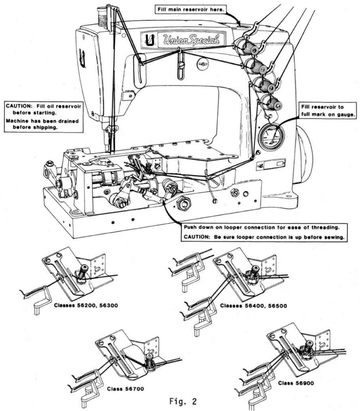
Fill main reservoir here. UnionSpecial CAUTION: Fill oil reservoir before starting. Machine has been drained before shipping. Fill reservoir to full mark on gauge. Push down on looper connection for ease of threading. CAUTION: Be sure looper connection is up before sewing. Classes 56200, 56300 Classes 56400, 56500 Class 56700 Class 56900 Fig. 2THREADING AND OILING DIAGRAM FOR ALL STYLES EXCEPT 56300 E,F,G,N,R,U,X,AH and AL
Oil has been drained from machine before shipping and the reservoir must be filled before starting to operate. Maintain oil level in "OPERATE" zone; add oil when needle of gauge registers on the black line marked "LOW". Machine is automatically lubricated and no oiling other than keeping the main reservoir filled is necessary. Refer to instructions under "LUBRICATION" and "CHANGING STITCH LENGTH" for additional information.
Thread machine as illustrated above for all Styles except 56300 E,F,G,N,R,U,X, AH and AL.
text_image
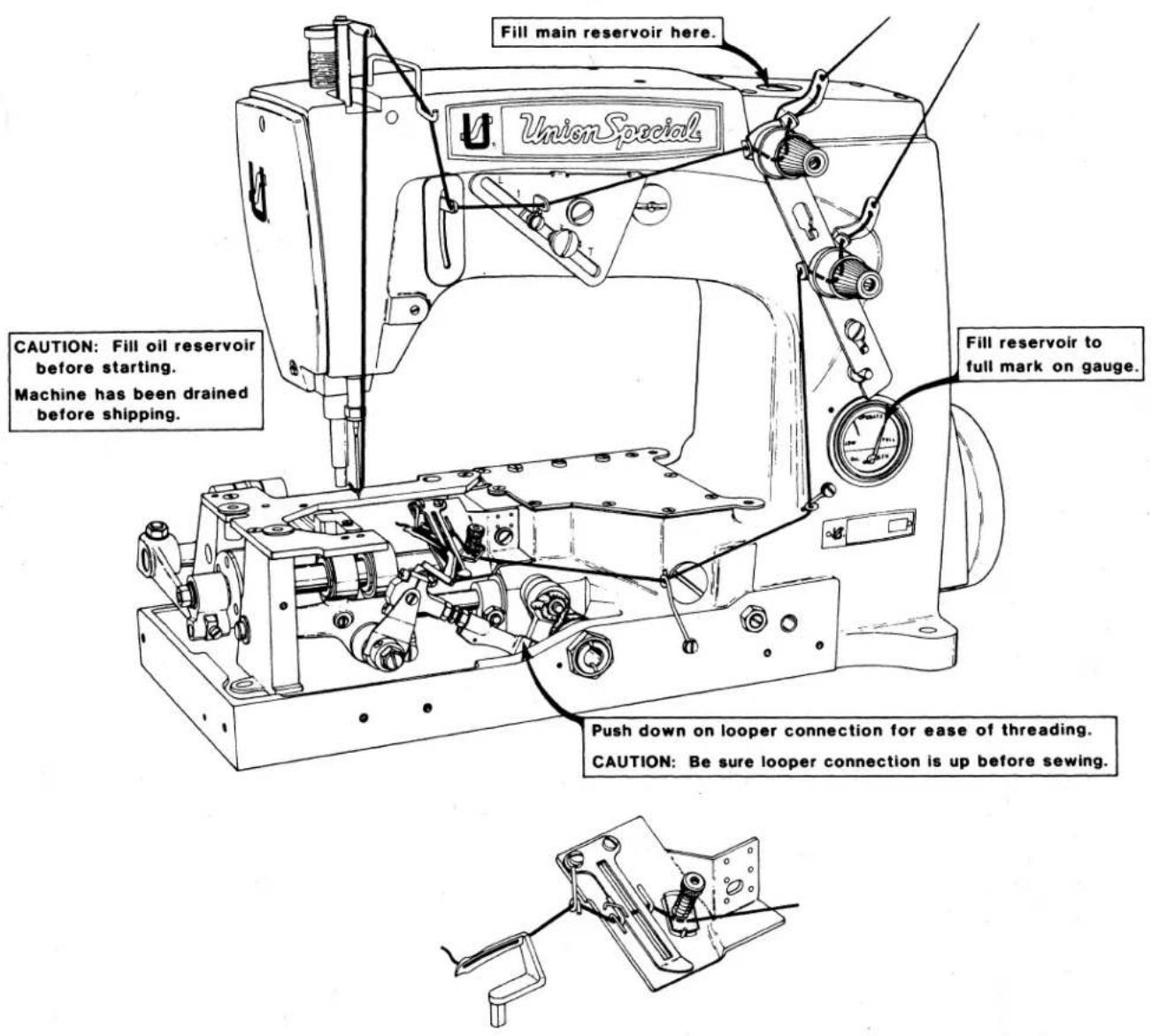
Fill main reservoir here. UnionSpecial CAUTION: Fill oil reservoir before starting. Machine has been drained before shipping. Fill reservoir to full mark on gauge. Push down on looper connection for ease of threading. CAUTION: Be sure looper connection is up before sewing.Fig. 2A
THREADING AND OILING DIAGRAM
FOR STYLES 56300 E,F,G,N,R,U,X,AH and AL
Oil has been drained from machine before shipping and the reservoir must be filled before starting to operate. Maintain oil level in "OPERATE" zone; add oil when needle of gauge registers on the black line marked "LOW". Machine is automatically lubricated and no oiling other than keeping the main reservoir filled is necessary. Refer to instructions under "LUBRICATION" and "CHANGING STITCH LENGTH" for additional information.
Thread machine as illustrated above for Styles 56300 E,F,G,N,R,U,X,AH and AL.
ADJUSTING INSTRUCTIONS
NOTE: Instructions stating direction or location, such as right, left, front or rear of machine, are given relative to operator's position at the machine. The handwheel rotates counterclockwise, in operating direction; when viewed from the right end of machine.
OIL GAUGE CALIBRATION
To recalibrate oil gauge, follow instructions in sequence as listed:
- Place machine upright on a level surface.
- Remove plug screw (C, Fig. 1) and tip machine forward to drain all oil from reservoir.
- Remove lower crank chamber cover on back of machine.
- Fill reservoir until oil is even with bottom of knee press shaft bushing (D).
- Loosen locknut (E) and rotate calibrating screw (F) as required until gauge needle registers on the black line marked "LOW".
- Tighten locknut (E), then replace plug screw (C) and lower crank chamber cover.
- Fill machine with oil until gauge needle registers on black line marked "FULL".
text_image
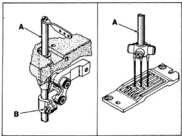
Technical diagram showing two mechanical assembly views labeled A and B, with component details and mounting brackets.Fig. 3
text_image
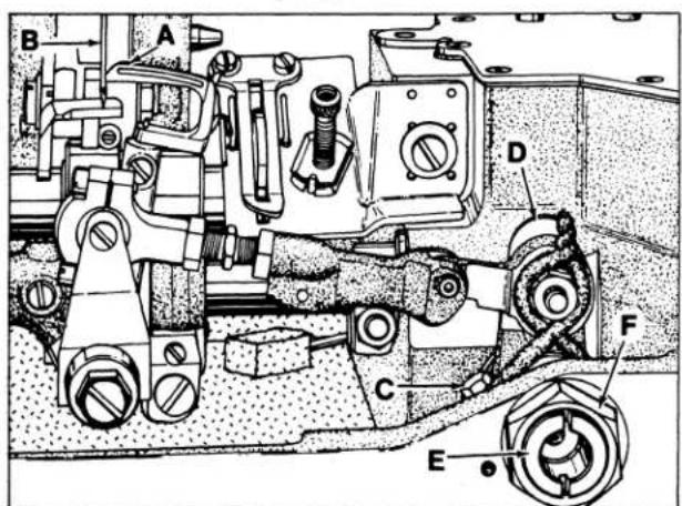
Technical diagram of a mechanical assembly with labeled parts A through FFig. 4
NEEDLE BAR ALIGNMENT (TWO AND THREE NEEDLE MACHINES)
Insert a new set of needles (type and size required). Turn handwheel to bring needle bar (A, Fig. 3) down to ensure that needles center in needle holes of throat plate as shown in Fig. 3. Adjustment can be made by loosening screw (B) slightly, allowing needle bar to be turned as required. Tighten clamp screw.
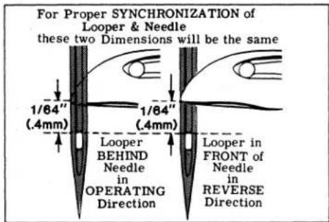
SYNCHRONIZING LOOPER AND NEEDLE MOTIONS
Insert looper into the looper rocker, pushing it all the way down and tighten screw against flat on shank of looper. Turn handwheel in operating direction until the point of the looper (A, Fig. 4) moving to the left, is even with the left side of the right needle (B). Note the height of the eye of the needle with respect to the looper point (See Fig. 5). Turn the handwheel in the reverse direction until the point of looper again moving to the left, is even with the left side of right needle (See Fig. 5). If the height of the eye of the needle with respect to the looper point are the same, looper and needle motions are synchronized - a variation of .005 inch (.127mm) is allowable.
SYNCHRONIZING LOOPER AND NEEDLE MOTIONS (Continued)
If the distance from the eye of the needle to the point of the looper is greater when the handwheel is turned in the operating direction, the looper drive lever rocker shaft will have to be moved slightly towards the rear. Moving the shaft towards the front acts the reverse.
NOTE: The 1/64 inch (.4mm) dimension shown in Fig. 5 is for final setting of needle bar height.
Adjust looper drive rocker lever shaft as follows:
text_image
For Proper SYNCHRONIZATION of Looper & Needle these two Dimensions will be the same 1/64" (.4mm) 1/64" (.4mm) Looper BEHIND Needle in OPERATING Direction Looper in FRONT of Needle in REVERSE DirectionFig. 5
Loosen screw (C, Fig. 4) in looper drive lever (D). A rod of .146-40 thd. or Union Special Screw No. 22870 A can be threaded into the looper drive lever rocker shaft through the center of thrust adjusting screw (E). Tap or pull slightly as required to position shaft for proper synchronization. Tighten screw (C) securely and remove rod or screw used to position shaft. Loosen lock nut (F) and TORQUE thrust adjusting screw (E) to 6 in. lbs. (7cm/kg); re-tighten lock nut (F) securely.
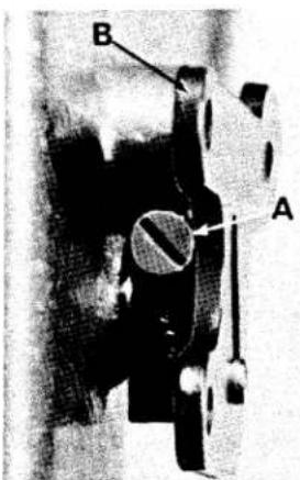
With looper at extreme right end of its travel, check location of the centerline of right looper connecting rod bearing using gauge No. 21227 CX for all Classes except 56700 which uses gauge No. 21227 CX-56 for Style 56700 J-56 and No. 21227 CX-64 for Style 56700 J-64. Remove nut from looper lever stud (A, Fig. 6) and place hole in gauge (B) over threaded stud. The left end of gauge should locate against the RIGHT side of looper rocker cone (C). If adjustment is necessary, loosen clamp screw (D), reposition looper drive lever (E) as required and retighten screw (D). If gauge is not available, setting can be checked with a scale. "X" dimension is from centerline of stud (A) to centerline of cone (C) which should be 4 1/16 inch (103.2mm) for all Classes except 56700. Style 56700 J-56 should be a 3 5/8 inch (92.1mm) and Style 56700 J-64 should be 3 9/16 inch (90.6mm) with looper at extreme right end of travel.
LOOPER SETTINGS

text_image
Technical diagram of a mechanical assembly with labeled components A, B, C, D, E and dimension XFig. 6
text_image
A B 32 5 C H F E G 41-40-900Fig. 7
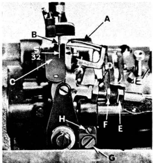
Insert a new needle, type and size as specified. If the looper gauge is 5/32 inch (4.0mm), for example, set the looper (A, Fig. 7) so the distance from the center of the needle (B) to the point of the looper is 5/32 inch (4.0mm), when the looper is at its farthest position to the right.
LOOPER SETTINGS (Continued)
Looper gauge No. 21225-5/32 (C) can be used advantageously in making this adjustment. On two needle machines set the back looper to the right needle and on three needle machines set the middle looper to the middle needle, when setting the looper gauge. Refer to chart for needle Type, looper gauge setting and looper gauge number. If adj-ment is required, loosen nut (D) (it has a left hand thread) and nut (E) on connect-ing rod (F), turn the connecting rod forward or backward to obtain the 5/32 inch (4.0mm) dimension. Retighten both nuts, first nut (E), then nut (D). Make sure the left ball joint is in vertical position and does not bind after adjustment.
| Machine Styles | Needle Type | Looper Gauge Setting | Looper Gauge Number |
| 56200 H | 101 GS | 1/8 Inch (3.2mm) | 21225-1/8 |
| 56200 K,R | 106 GLS | 1/8 Inch (3.2mm) | 21225-1/8 |
| 56200 L | 126 GS | 5/32 Inch (4.0mm) | 21225-5/32 |
| 56200 S | 108 GHS | 1/8 Inch (3.2mm) | 21225-1/8 |
| 56200 W, 56300 W,AL | 128 GAS | 5/32 Inch (4.0mm) | 21225-5/32 |
| 56300 E,F,G,N,R,U,X,AH | 128 GBS | 5/32 Inch (4.0mm) | 21225-5/32 |
| 56300 H | 143 GS | 5/32 Inch (4.0mm) | 21225-5/32 |
| 56300 M | 126 GS | 5/32 Inch (4.0mm) | 21225-5/32 |
| 56400 D | 106 GHS | 1/8 Inch (3.2mm) | 21225-1/8 |
| 56400 P,R,S,T,W,X | 106 GHS | 1/8 Inch (3.2mm) | 21225-1/8 |
| 56500 A,B,C,U | 130 GS | 5/32 Inch (4.0mm) | 21225-5/32 |
| 56500 J,R | 128 GS | 5/32 Inch (4.0mm) | 21225-5/32 |
| 56700 J | 108 GKS | 1/8 Inch (3.2mm) | 21225-1/8 |
| 56900 H | 128 GAS | 5/32 Inch (4.0mm) | 21225-5/32 |
| 56900 J | 147 GKS | 7/32 Inch (5.6mm) | 21225-7/32 |
| 56900 P | 147 GKS | 5/32 Inch (4.0mm) | 21225-5/32 |
| 56900 R | 147 GS | 7/32 Inch (5.6mm) | 21225-7/32 |
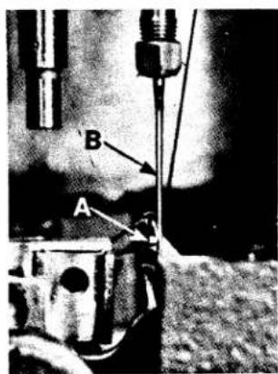
The looper is set correctly if, as it moves to the left behind the needle, its point (A, Fig. 8) clears the rear of needle (B) by .002 inch (.051mm).
text_image
B AFig. 8
If adjustment is necessary, loosen lock screw (G, Fig. 7) and turn stop screw (H) as required. Turning stop screw clockwise sets the looper to the rear and turning it counterclockwise acts the reverse. Holding looper to the front while making this adjustment may prove helpful. Tighten lock screw when setting is obtained and recheck the adjustment.
On Style 56200 W, looper needle guard (attached to looper) should be set to barely contact the front of needle without deflecting as looper moves to left.
On the two and three needle machines, insert the other needles and loopers. The same looper - needle relationship should exist without any adjustment, other than applying pressure on the looper at front or back of blade, while clamping looper in looper rocker, so as to get the proper in-line-of-feed setting.
NEEDLE BAR HEIGHT
The height of the needle is correct when the top of its eye is 1/64 inch (.4mm) below the underside of the looper, with the looper point flush with the left side of the needle as shown in Fig. 5. On Styles 56500 A, B and C the top of the needle eyes should be even with the underside of the looper when the looper point is flush with the left side of the needle. If adjustment is necessary, loosen screw (B, Fig. 3) and move needle bar (A) up or down as required and retighten screw. On two and three needle machines, care should be taken not to disturb alignment of needle bar when moving the needle bar either up or down. The descending needles must be deflected alike on the back of the loopers.

text_image
B A C DFig. 9
FEED DOG SETTINGS
Feed dog (A, Fig. 9) should be centered in throat plate (B) with equal clearance on all sides and ends with feed travel set to desired stitch length. At highest point of travel, tips of feed dog teeth should extend the depth of a tooth or approximately 3/64 inch (1.2mm) above throat plate and parallel to same. Screw (C) should be set to support feed dog after screw (D) has been loosened which secures feed dog in position.
On Styles 56300 N,U,X,AH the tips of the teeth must extend 1/32 inch (.8mm) above the throat plate and the "Grip Feed" presser foot feed dog must line with the lower feed dog left to right, and in-line-of-feed the last teeth of the top and bottom feeds should match tooth point to point.

text_image
Black-and-white photo of a vintage agricultural machine with labeled parts (A, B, C, D, E) and workers in the background.Fig. 10
Parallel adjustment can be made by loosening nut (A, Fig. 10) and turn screw (B) clockwise to lower front of feed dog, counterclockwise acts the reverse. When properly set, retighten nut (A).
Right to left adjustment can be made by loosening screws (A, Fig. 11) and slightly move feed rocker (B) on feed rocker shaft (C) as required, then retighten screws. Check to ensure that feed rocker arm (D) does not bind after adjustment.
Forward or rearward centering of feed dog can be accomplished by loosening nut (E, Fig. 11), move feed rocker (B) as required and re-tighten nut.

text_image
Technical diagram of a mechanical assembly with labeled parts A through L, showing structural components and directional arrows.Fig. 11
CHANGING STITCH LENGTH
Set the stitch to required length. This is accomplished by loosening locknut (F, Fig. 11) 1/2 turn (it has a left hand thread) on the end of the stitch regulating stud and turning stitch adjusting screw (G) located under the left end of the cloth plate, in the head of main shaft (H), which is marked with "L" and "S". Turning the screw clockwise shortens the stitch (moves stitch regulating stud toward the "S") and turning it in a counterclockwise direction lengthens the stitch (moves stitch regulating stud toward the "L"). Retighten locknut securely. To prevent destructive damage to the feed drive bearing, key screw (J) must engage the "U" shaped key slot in ferrule (K).
NOTE: Any change in stitch length will necessitate a corresponding change in the rear needle guard setting.
Machines having needle bearings in the feed rocker at locations (L, Fig. 11) may require repacking after years of service. Bearings should be thoroughly cleaned and repacked with Union Special Corporation grease No. 28604 P.
REAR NEEDLE GUARD
At extreme forward end of travel, rear needle guard (C, Fig. 10) must be set horizontally not to contact rear of needle (D) with a maximum clearance of .005 inch (.127mm). Guard should be set as low as possible, yet have its vertical face approach approximately 3/64 inch (1.2mm) of needle point until point of looper (E), moving to the left, is even with the needle. To move needle guard forward or backward, loosen screw (F), move needle guard as required, and retighten screw. To raise or lower needle guard, loosen screw (F), and turn screw (G) clockwise to lower needle guard or counterclockwise to raise it. Retighten screw (F) after guard is properly set.
NOTE: Any change in stitch length will require a change in rear needle guard setting.
THREADING (FOR ALL STYLES EXCEPT 56300 E,F,G,N,R,U,X,AH and AL)
Draw the looper and needle threads into the machine and start operating on a piece of fabric. Refer to threading diagram (Fig. 2) for the threading of these machines.
THREAD TENSIONS
The tension on the needle thread should be only sufficient to produce uniform stitches on the under surface of the fabric.
The looper thread tension is applied at the cast-off support tension disc assembly, and the adjusting nut should be set so that the tension on the looper thread is just sufficient to steady the thread.
THREAD TENSION RELEASE
The thread tension release is set correctly when it begins to function as the presser foot is raised to within 1/8 inch (3.2mm) of the end of its travel and is entirely released when the presser foot has reached its highest position.
THREAD TENSION RELEASE (Continued)
If adjustment is required, loosen tension release lever screw (A, Fig. 12), located at the back of machine and move tension disc separator as required. Retighten screw. After adjustment there should be no binding at any point.
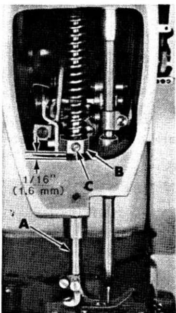
PRESSER BAR HEIGHT
Height of presser bar (A, Fig. 13) is correct when presser foot can be removed by depressing foot lifter lever (B, Fig. 12). There should be approximately 1/16 inch (1.6mm) clearance between lower surface of presser bar connection and guide (B, Fig. 13) and bottom surface of head opening in bed casting when foot lifter lever is released and presser foot lying flat on throat plate with feed dog below throat plate.
text_image
B AFig. 12
Adjustment can be made by turning handwheel to position needle bar at bottom of stroke. Loosen screw (C, Fig. 13) and while holding presser foot down on throat plate, position presser bar connection and guide as required to attain specified clearance and retighten screw.
PRESSER FOOT PRESSURE
Regulate presser spring regulating screw (A, Fig. 14) so that it exerts only enough pressure on the presser foot to feed the work uniformly when a slight tension is placed on the fabric. Turning it clockwise increases the pressure, counterclockwise acts the reverse.
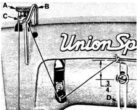
NEEDLE THREAD TAKE-UP WIRE AND FRAME EYELET (FOR ALL STYLES EXCEPT 56300 E,F,G,N,R,U,X,AH and AL)
Set needle thread take-up wire (B, Fig. 14), so that its upper surface is even with the top of the holes in needle bar thread eyelet (C) when needle bar has completed its downward stroke. Lower this setting for a smaller needle thread loop, or raise it for a larger loop. Set needle thread frame eyelet (D) so that the eyelet hole is 3/4 inch (19.0mm) above the attaching screw on all Styles except on Styles 56500 J, 56900 H, J, P and R the eyelet is to be set 5/8 inch (15.9mm) above the attaching screw and on Style 56200 H the eyelet is to be set 1 inch (25.4mm) above the attaching screw.
NOTE: For the above setting on Styles 56300 E,F,G,N,R,U,X,AH and AL, see the following paragraphs.
THREADING (FOR STYLES 56300 E,F,G,N,R,U,X,AH and AL)
Refer to threading diagram (Fig. 2A) for the manner in which these machines are threaded.
text_image
1/16" (1.6 mm) A B CFig. 13
text_image
A B C Union Sp 3 4 DFig. 14
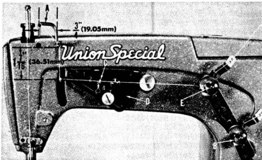
NEEDLE THREAD TAKE-UP WIRE AND FRAME EYELET FOR (STYLES 56300 E,F,G,N,R,U,X,AH and AL)
text_image
3" (19.05mm) Union Special 1/16 (36.51mm) C D EFig. 14A

text_image
A B 3/4 (19.05mm)Fig. 15
These machine styles are equipped with additional thread handling and control parts, so the adjusting sequence should be made in the following manner:
With needle bar at the top of its stroke, set needle thread take-up wire (A, Fig. 14A) so its lower extended surface is 1 7/16 inch (36.5mm) above centerline of needle lever thread eyelet hole and 3/4 inch (19.0mm) across the centerlines of its vertical surfaces (See Fig. 14A).
text_image
Technical diagram of a mechanical device with labeled parts A, B, C, D, and EFig. 16
Set looper thread guide eyelet (A, Fig. 15) so its left outer surface is 3/4 inch (19.0mm) from the left side of looper thread take-up (B), (See Fig. 15).
Adjust looper thread tension with nut (B, Fig. 14A) to a minimum required for controlling the looper thread (light). Set the thread index eyelet (C) at "3" on the adjusting plate (D). Changing the needle thread tension only, with nut (E), balance the stitch so that when 6 inches (152.4mm) of sewn seam are raveled back, the needle thread is approximately as long as the looper thread. A 1 inch (25.4mm) difference in lengths is permissible. NOTE: Use a sample of the material to be sewn. Maintaining this needle thread tension, move thread index eyelet (C) up to toward "L" to obtain a looser seam (longer needle loops) and toward "T" to obtain a tighter seam.
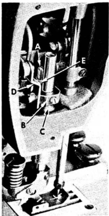
FEEDING PRESSER FOOT
Remove the presser spring regulator and presser spring. Adjust long stop screw (A, Fig. 16) in presser bar guide (B) against bed casting as required to ensure a clearance between the guide and top of presser bar bushing (C), yet so that guide is pulled up quickly by lifter lever link (D) when foot treadle is activated. Tighten lock nut (E) on stop screw.
FEEDING PRESSER FOOT (Continued)
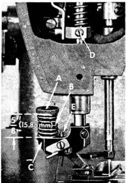
As a preliminary setting, adjust spring regulator nut (A, Fig. 17) on feeding presser foot so the distance from the top of spring (B) to the yoke (C) is 5/8 inch
(15.9mm), (See Fig. 17). Assemble the feeding presser foot to presser bar. With presser foot resting on throat plate and feed dog down, press down on spring regulator nut (A, Fig. 17) until the marks on presser foot bottom line up with the centerline of needle, while keeping the needle in the center of needle slot, tighten set screw (D) securing presser bar guide to the presser bar, making sure stop screw in presser bar guide is resting on the bed casting.
Replace presser spring and presser spring regulator. Turn presser bar spring regulator screw down until the thread portion is level with the head casting.
NOTE: Any change in the alignment of needle in relationship to the marks on the presser foot bottom probably means that the stop screw of the presser bar guide was not seated against bed casting before locking set screw.
text_image
A B C D E 5" (15.88 mm) 8Fig. 17
When the presser foot is lifted off the bare throat plate, the foot should move back only slightly, less than 1/64 inch (.4mm). The stop screw (E, Fig. 17) the factory, can be readjusted if necessary, should this on the yoke, which is set at dimension become changed.
CHECK
Presser foot at back of needle slot should cover most of throat plate land when resting on the bare throat plate.
When the presser foot bottom is raised by material so that the feeding foot spring bottoms, the back of the needle slot should clear the needle. The main presser bar should not lift before the feeding foot spring bottoms.
The purpose of the feeding foot is to make the top and bottom ply of cloth feed the same amount without pulling on the bottom ply. The 5/8 inch (15.9mm) setting on the feeding foot spring usually gives a good matching of piles and a strong feeding pull. Reducing this pressure will tend to feed the top ply more. Increasing this pressure will tend to feed the bottom ply more.
TORQUE REQUIREMENTS
Torque specifications given in this catalog are measured in inch-pounds or centimeter/kilograms. All straps and eccentricities must be tightened to 19-21 in. lbs. (22-24cm/kg) unless otherwise noted. All nuts, bolts, screws, etc., without torque specifications must be secured as tightly as possible, unless otherwise noted. Special torque specifications for connecting rods, links, screws, etc., are shown on parts illustrations.
text_image
Technical diagram of a mechanical assembly with labeled parts A through K, showing exploded and assembled views.Fig. 18
text_image
C A A C 1/32" (8mm) D F B F EFig. 19

text_image
.045'' (1.14mm)Fig. 20
SPECIAL INSTRUCTIONS
NEEDLE LEVER
When adjusting needle lever or replacing related parts, follow instructions in sequence as listed:
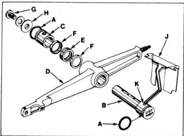
- Install "0" rings (A, Fig. 18) onto needle lever stud (B) and thrust collar (C).
- With needle lever (D) in machine and positioned properly; insert stud (B) through hole in needle lever until its shoulder contacts the needle lever and the word "UP" on stud is in the upright position. While making sure no binding exists in the needle bar link, secure stud (B) with the front set screw in top of machine bed.
- Install temper load ring (E) and compression cups (F) onto stud (B), then push ring and cups through opening in machine bed.
- Install thrust collar (C) onto stud (B) being careful not to damage "O" ring. Compress components together by tightening screw (G) until washer (H) bottoms against stud (B). Secure stud (B) in position using the rear set screw in top of bed.
- To check temper load ring for proper compression, remove screw (G) from stud (B) and loosen rear set screw in top of bed. Thrust collar (C) should spring out .003 - .007 inch (.08 - .18mm). Compress load ring in reverse order, then tighten rear set screw.
- With indented "UP" on stud (B) in upright position, install bearing oiler (J) so its hook sets in oil supply hole (K) of stud. When hook and stud are secured in their proper positions, the proper amount of oil will be channeled to stud for lubricating needle lever (D).
ALIGNING MAINSHAFT TO CRANKSHAFT
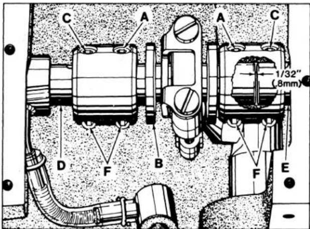
As viewed looking down from rear of machine, spot screws (A, Fig. 19) in the couplings must align with the spots in the looper drive crank (B) and set screws (C) must align with the flats on crankshaft (D) and mainshaft (E). Mainshaft must be positioned laterally with .045 inch (1.14mm) clearance between the right side of its head and the bed casting as shown in Fig. 20.
ALIGNING MAINSHAFT TO CRANKSHAFT (Continued)
Looper drive Crank (B, Fig. 19) must be positioned laterally with 1/32 inch (.8mm) clearance between it and mainshaft (E) as shown in Fig. 19. Once these settings are made, it is very important that the couplings are tightened in the following sequence for best performance.
Tighten spot screws (A) temporarily, to the looper drive crank. Tighten set screws (C) temporarily, to the crankshaft and mainshaft. Torque screws (F) to 19 - 21 in. 1bs. (22-24cm/kg). Loosen spot screws (A) and set screws (C). Re-torque screws (F) to 19-21 in. 1bs. (22 - 24cm/kg), then, torque screws (A and C) to 19-21 in. 1bs. (22 - 24cm/kg).
The oil drip plate (A, Fig. 21) located in the oil reservoir should be positioned with its tip in the recessed cut out in the bed casting, as far to the left as possible without touching. It has elongated mounting holes and can be adjusted by loosening (2) screws (B) in top of the oil reservoir back cover to position as required, retighten screws.

text_image
Technical diagram of a mechanical assembly with labeled components A and B, showing structural components and mounting points.Fig. 21
ORDERING REPAIR PARTS
ILLUSTRATIONS
This catalog has been arranged to simplify ordering repair parts. Exploded views of various sections of the mechanism are shown so that the parts may be seen in their actual position in the machine. On the page opposite the illustration will be found a listing of the parts with their part numbers, descriptions and the numbers of pieces required in the particular view being shown.
Numbers in the first column are reference numbers only and merely indicate the position of that part in the illustration. Reference numbers should never be used in ordering parts. Always use the part number listed in the second column.
Component parts of sub-assemblies which can be furnished for repairs are indicated by indenting their descriptions under the description of the main sub-assembly. Example:
| 9 | 29105 AK | Looper Drive Lever Crank Assembly, for Styles 56200 L, W,Classes 56300, 56500 and 56900 | 1 |
| 10 | 22559 A | Bearing Cap Screw, lower | 2 |
| 11 | 56343 E | Oil Splasher | 1 |
| 12 | 56343 C | Ball Joint Guide Fork | 1 |
| 13 | 22587 K | Bearing Cap Screw, upper | 1 |
It will be noted in the above example that the eccentric, ball stud and bearing are not listed. The reason is that replacement of these parts individually is not recommended, so the complete sub-assembly should be ordered.
At the back of the book will be found a numerical index of all the parts shown in this book. This will facilitate locating the illustration and description when only the part number is known.
IDENTIFYING PARTS
Where the construction permits, each part is stamped with its part number. On some of the smaller parts and on those where construction does not permit, an identification letter is stamped in to distinguish the part from similar ones.
Part numbers represent the same part, regardless of catalog in which they appear.
IMPORTANT! ON ALL ORDERS, PLEASE INCLUDE PART NAME AND STYLE OF MACHINE FOR WHICH PART IS ORDERED.
TERMS
Prices are net cash and subject to change without notice. All shipments are forwarded f.o.b. shipping point. Parcel Post shipments are insured unless otherwise directed. A charge is made to cover postage and insurance.
Before this machine left the factory it was adjusted and inspected to give you the utmost satisfaction and durability at all times. If, however, the machine has been readjusted and is not sewing properly, see chart below for suggestions which may prove beneficial to you.
SKIPPED STITCHES
| Condition | Causes | Cures |
| Needle loop too small | Take-up wire set too low | Raise take-up wire slightly |
| Needle thread stretched at bottom of stroke, loop not formed till stretch relieved | Lower frame thread eyelet and/or reduce needle tension | |
| Needle thread creased because it is too tight and needle is hot | Use oversize ball eye needle, lower frame needle eyelet, reduce tension | |
| Needle thread pinched by needle guard, collapsing needle loop | Drop needle guard slightly | |
| Thread twisting around needle | Keep needle loop as small as possible, keep needle thread tension to a minimum. Use a left twist thread | |
| Needle thread sticking in needle grooves, due to heat | Use oversize ball eye needle, to reduce friction | |
| Length of needle eye too long, causing delay in needle loop formation | Use needle with shorter eye, drop needle bar slightly or increase looper gauge 1/64 to 1/32 inch | |
| Needle does not rise enough to form needle loop properly | Increase looper gauge 1/64 to 1/32 inch | |
| Looper misses needle loop as presser foot is coming off a seam | Material is not held down in front of seam and is flagging | Use tractor type presser foot, if available, or see if presser bar is sticking |
| Needle deflecting toward operator | Use sharp point needle | |
| Needle loop formed properly but brushed out of the way by looper | Needle bar set too high | Lower needle bar slightly |
| Looper misses needle loop when operator is trying to match seams or ends of garments | Needle deflecting toward operator who may be holding back on material while matching seams or ends of garment | Do not hold back excessively on on material. Properly adjust feed and maintain a light presser foot pressure so operator does not hold back |
| Machine misses needle loop when stitch length is increased | Needle deflecting toward the operator because the needle guard is set too far forward | Move needle guard to the rear |
| Needle misses triangle on looper thread side | Looper thread too loose, not making a good triangle | Increase looper thread tension |
| Needle being deflected to the rear by burr on needle point or due to operator pulling on material, or needle glancing off when coming on a seam | Do not pull material at the back. Use a sharp needle to stop needle from glancing off seam. Check needle for burr |
NOTE: More detailed information concerning the double locked stitch (stitch type 401) is available under "Stitch Formation, Type 401".
text_image
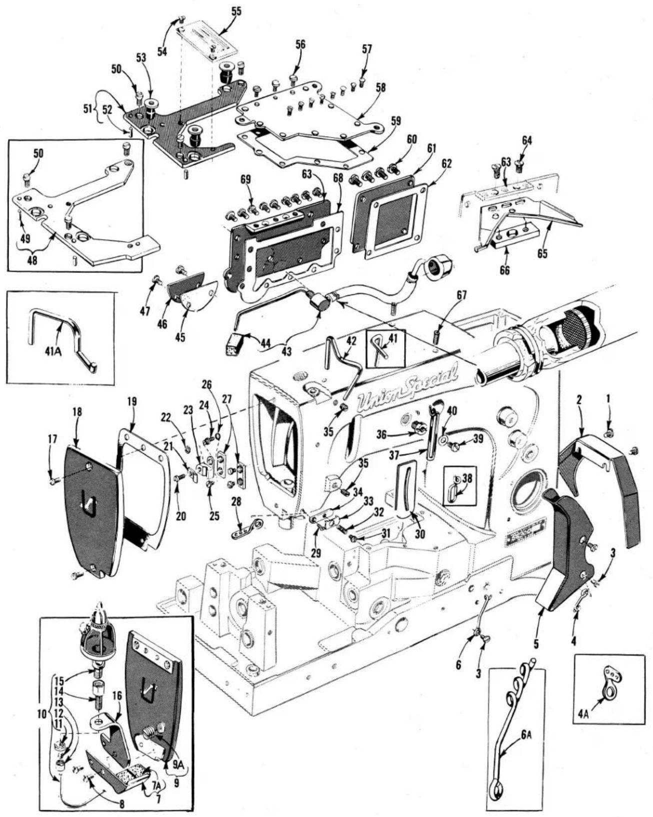
Exploded view diagram of a Union Special device with numbered parts and exploded viewsMAIN FRAME, THROAT PLATE SUPPORTS, MISCELLANEOUS COVERS AND OILING PARTS
| Ref.No. | PartNo. | Description | Amt.Req. |
| 1 | 22829 | Screw | 2 |
| 2 | 21375 AV | Belt Guard | 1 |
| 3 | 98 A | Screw | 3 |
| 4 | 52 A | Looper Thread Eyelet, for all Classes except 56900 | 1 |
| 4A | 158 A | Looper Thread Eyelet, for Class 56900 | 1 |
| 5 | 56391 | Looper Thread Guard | 1 |
| 6 | 52958 B | Looper Thread Eyelet, for single needle machines | 1 |
| 6A | 52958 G | Looper Thread Eyelet, for two and three needle machines | 1 |
| 7 | 21396 BP | Needle Thread Lubricator, for Class 56900 | 1 |
| 7A | 21396 AG | Felt Pad | 2 |
| 8 | 22569 B | Screw, for Class 56900 | 2 |
| 9 | 56782 | Head Cover, for Styles 56400 R, 56700 J, 56900 H, J, P, R | 1 |
| 9A | 22733 C | Plug Screw | 1 |
| 10 | 21396 BR | Needle Thread Lubricator Oil Reservoir, for Class 56900 | 1 |
| 11 | 11638 M | Nut | 1 |
| 12 | 660-74 | Connection Sleeve | 1 |
| 13 | 660-75 | Coupling- | 1 |
| 14 | 21396 AL | Adapter | 1 |
| 15 | 660-73 | Oil Cup | 1 |
| 16 | 21396 BK | Needle Thread Lubricator Oil Reservoir Bracket, for Class 56900 | 1 |
| 17 | 22569 C | Screw, for head cover | 2,3 |
| 18 | 56382 | Head Cover, for all Styles except 56400 R, 56700 J, 56900 H, J, P, R- | 1 |
| 19 | 56382 N | Gasket | 1 |
| 20 | 22585 | Screw | 1 |
| 21 | 56393 D | Head Oil Tube Clamp | 1 |
| 22 | 7947 | Nut | 1 |
| 23 | 56393 C | Head Oil Tube Mounting Block | 1 |
| 24 | 51294 R | Screw | 1 |
| 25 | 22513 | Screw | 3 |
| 26 | 660-342 | Lockwasher | 1 |
| 27 | 35731 A | Presser Bar Connection Guide Plate | 2 |
| 28 | 56958 B | Frame Needle Thread Eyelet, for Style 56900 J | 1 |
| 29 | 605 A | Screw, for Styles 56200 S, W; 56300 W, AL | 1 |
| - | 22836 | Screw for 56958 B, for Style 56900 J | 1 |
| 30 | 660-617 | Needle Lever Eyelet Gasket | 1 |
| 31 | 57 WD | Nipper Spring Screw, for Styles 56200 S, W; 56300 W, AL | 1 |
| 32 | 15438 C | Nipper Spring, for Styles 56200 S, W; 56300 W, AL | 1 |
| 33 | 57 WB | Nipper Spring Plate, for Styles 56200 S, W; 56300 W, AL | 1 |
| 34 | 43296 | Nipper Spring Base, for Styles 56200 S, W; 56300 W, AL | 1 |
| 35 | 95 | Plug Screw and Screw for take-up wire | 2 |
| 36 | 22889 A | Adapter Plug Screw | 1 |
| *37 | 539 | Frame Needle Thread Eyelet, for all Styles except 56300 E, F, G, N, R, U, X, AH, AL and 56700 J | 1 |
| *38 | 51758 | Frame Needle Thread Eyelet, for Style 56700 J | 1 |
| 39 | 22848 | Screw | 1 |
| 40 | 20 | Washer | 1 |
| 41 | 56470 | Needle Thread Take-up Wire, for Style 56300 M, Classes 56400, 56500, 56700, 56900 and 56200 except Style 56200 W | 1 |
| 41A | 56370 | Needle Thread Take-up Wire, for Styles 56300 E, F, G, N, R, U, X, AH, AL- | 1 |
| 42 | 51270 B | Needle Thread Take-up Wire, for Styles 56200 W; 56300 H, W | 1 |
| 43 | 59493 A | Base Oil Pump Assembly- | 1 |
| 44 | 666-214 | Intake Felt- | 1 |
| 45 | 56382 K | Gasket- | 1 |
| 46 | 56382 J | Looper Drive Shaft Reservoir Cover- | 1 |
| 47 | 22829 | Screw | 2 |
| 48 | 56480 | Throat Plate Support, for Styles 56200 H, K, L, W, 56300 H, M, AL and Classes 56400 56500, 56700, 56900- | 1 |
| 49 | 51280 J | Dowel Pin- | 2 |
| 50 | 22839 | Screw, for throat plate support | 3 |
| 51 | 56380 | Throat Plate Support, for Styles 56200 R, S and Class 56300 except Styles 56300 H, M, AL | 1 |
| 52 | 51280 J | Dowel Pin- | 2 |
| 53 | 660-313 | Well Nut- | 3 |
| 54 | 87 | Screw, for throat plate, countersunk head, for Styles 56200 R, S and Class 56300 except Styles 56300 H, M, AL- | 2 |
| 55 | Throat Plate (See Pages 47, 49, 51, 55, 57, 59, 61, 63, 65) | 1 | |
| 56 | 22585 A | Screw | 3 |
| 57 | 22524 | Screw | 8 |
| 58 | 56382 G | Oil Reservoir Top Cover | 1 |
| 59 | 56382 H | Gasket- | 1 |
| 60 | 22548 | Screw | 4 |
| 61 | 56382 D | Crank Chamber Cover, lower- | 1 |
| 62 | 56382 E | Gasket- | 1 |
| 63 | 56382 AA | Oil Reservoir Back Cover- | 1 |
| 64 | 87 | Screw | 2 |
| 65 | 56382 AB | Oil Drip Plate- | 1 |
| 66 | 56382 Y | Oil Drip Plate Clamping Block | 1 |
| 67 | 22894 E | Screw | 2 |
| 68 | 56382 L | Gasket- | 1 |
| 69 | 22848 | Screw | 9 |
*See Page 35 for thumbscrew adjustable frame needle thread eyelet assembly No. 29476 MY for Styles 56300 E, F, G, N, R, U, X, AH and AL.

text_image
FILL MAIN RESERVOIR HERE Union Special 25 26 27 24 23 22 21 18 19 20 18 17 18 19 18 15 16 14 13 12 11 10 39 38 37 36 35 34 33 32 31 30 29 28 27 26 25 Union SpecialMAIN FRAME, BUSHINGS, OIL GAUGE AND MISCELLANEOUS OILING PARTS
| Ref.No. | PartNo. | Description | Amt.Req. |
| 1 | 22793 | Screw - - - - - - - - - - - - - - - - - - - - - - - - - - - - - - - - - - - - - - - - - - - - - - - - - - - - - - - - - - - - - - - - - - - - - - - - - - - - - - - - - - - - - - - - - - - - - - - - - - - - | 1 |
| 2 | 22539 R | Plug Screw- - - - - - - - - - - - - - - - - - - - - - - - - - - - - - - - - - - - - - - - - - - - - - - - - - - - - - - - - - - - - - - - - - - - - - - - - - - - - - - - - - - - - - - - - - - - - - - - - - - - | |
| 3 | 56342 D | Nut - - - - - - - - - - - - - - - - - - - - - - - - - - - - - - - - - - - - - - - - - - - - - - - - - - - - - - - - - - - - - - - - - - - - - - - - - - - - - - - - - - - - - - - - - - - - - - - - - - - | |
| 4 | 56394 A | Oil Gauge Adjusting Shaft - - - - - - - - - - - - - - - - - - - - - - - - - - - - - - - - - - - - - - - - - - - - - - - - - - - - - - - - - - - - - - - - - - - - - - - - - - - - - - - - - - - - - - - - - - - - - - - - - - - 1 | |
| 5 | 11635 B | Nut - - - - - - - - - - - - - - - - - - - - - - - - - - - - - - - - - - - - - - - - - - - - - - - - - - - - - - - - - - - - - - - - - - - - - - - - - - - - - - - - - - - - - - - - - - - - - - - - - 1 | 1 |
| 6 | 61256 G | Washer- - - - - - - - - - - - - - - - - - - - - - - - - - - - - - - - - - - - - - - - - - - - - - - - - - - - - - - - - - - - - - - - - - - - - - - - - - - - - - - - - - 2 | |
| 7 | 660-221 | Oil Retaining Ring- - - - - - - - - - - - - - - - - - - - - - - - - - - - - - - - - - - - - - - - - - - - - - - - - - - - - - - - - - - - - - - - - - - - - - - - - 1 | |
| 8 | 56394 C | Oil Gauge Float Lever Assembly- - - - - - - - - - - - - - - - - - - - - - - - - - - - - - - - - - - - - - - - - - - - - - - - - - - - - - - - - - - - - 1 | |
| 9 | 56394 B | Oil Gauge Connecting Rod- - - - - - - - - - - - - - - - - - - - - - - - - - - - - - - - - - - - - - - - - - - - - - 1 | |
| 10 | 63494 K | Oil Gauge - - - - - - - - - - - - - - - - - - - - - - - - - - - - - - - - - - - - - - - - - - - - - - - 1 | |
| 11 | 660-455 | "O" Ring - - - - - - - - - - - - - - - - - - - - - - - - - - - - - - - - - - - - - - - - - 1 | |
| 12 | 63494 G | Spring Washer- - - - - - - - - - - - - - - - - - - - - - - - - - - - - - - - - - - - - - - - - - - - - 1 | |
| 13 | 63494 F | Nut- - - - - - - - - - - - - - - - - - - - - - - - - - - - - - - - - - - - - - - - 1 | |
| 14 | 56390 E | Bushing Housing Gasket- - - - - - - - - - - - - - - - - - - - - - - - - - - - 1 | |
| 15 | 57890 B | Crankshaft Bushing Housing- - - - - - - - - - - - - - - - - - - - - - - - - 1 | |
| 16 | 22569 B | Screw - - - - - - - - - - - - - - - - - - - - - - - - - - - 3 | |
| 17 | 21657 X | Tension Release Lever Shaft Bushing | - 1 |
| 18 | 56390 H | Thrust Washer | - 4 |
| 19 | 56390 J | Pilot Ring- | - 2 |
| 20 | 660-665 | Needle Thrust Bearing | - 2 |
| 21 | 56382 AC | Needle Lever Bearing Oiler and Baffle Plate Assembly- | - 1 |
| 22 | 90 | Screw | - 2 |
| 23 | 56382 C | Gasket- | - 1 |
| 24 | 56382 B | Upper Crank Chamber Cover | - 1 |
| 25 | 22541 C | Screw | - 4 |
| 26 | 22733 E | Oil Filler Plug Screw | - 1 |
| 27 | 56382 M | Gasket- | - 1 |
| 28 | 51154 E | Needle Bar Bushing, upper | - 1 |
| 29 | 56393 W | Oil Attraction Felt | - 1 |
| 30 | 57836 B | Feed Rocker Shaft Bushing | - 2 |
| 31 | 666-259 | Felt- | - 1 |
| 32 | 56390 | Main Shaft Bushing, left- | - 1 |
| 33 | 50-895 Blk. | Looper Rocker Shaft Bushing | - 2 |
| 34 | 56393 P | Base Felt, front- | - 1 |
| 35 | 52942 W | Looper Drive Lever Shaft Bushing, front | - 1 |
| 36 | 52942 AC | Thrust Adjusting Screw- | - 1 |
| 37 | 35897 BV | Oil Intake Filter | - 1 |
| 38 | 56393 Q | Base Felt, rear | - 1 |
| 39 | 56390 G | Main Shaft Bushing, right | - 1 |
| 40 | GR-56393 T | Head Oil Pump Assembly- | - 1 |
| 41 | 56393 L | Intake Felt- | - 1 |
| 42 | 56354 C | Needle Bar Bushing, lower, for all Styles except 56900 J, P, R- | - 1 |
| Needle Bar Bushing, lower, for Styles 56900 J, P, R- | - 1 | ||
| - | 57954 | Presser Bar Bushing, lower- | - 1 |
| 43 | 51257 AA | Looper Drive Lever Shaft Bushing, rear- | - 1 |
| 44 | 57842 B | Main Shaft Bushing, intermediate- | - 1 |
| 45 | 56190 |
text_image
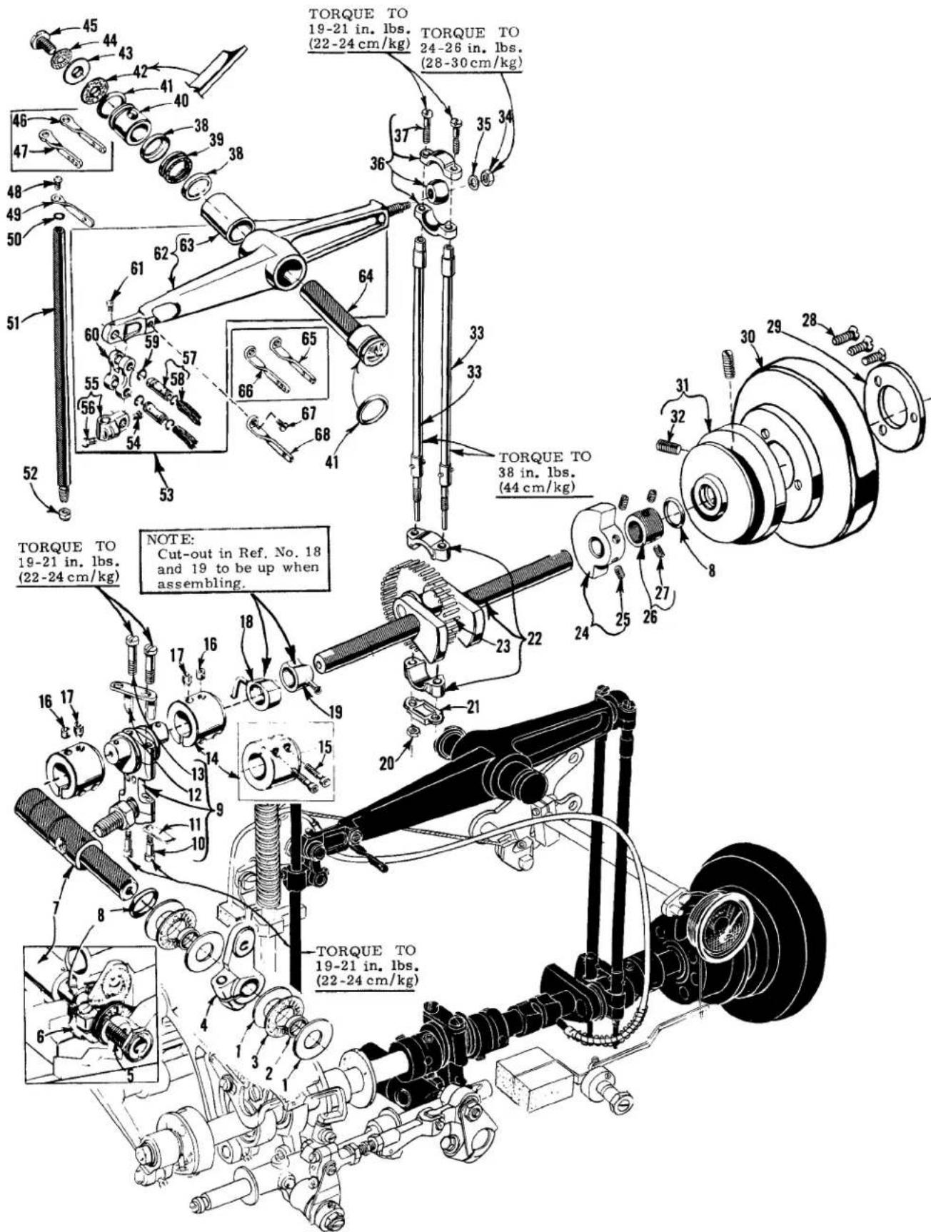
TORQUE TO 19-21 in. lbs. (22-24 cm/kg) TORQUE TO 24-26 in. lbs. (28-30 cm/kg) TORQUE TO 38 in. lbs. (44 cm/kg) NOTE: Cut-out in Ref. No. 18 and 19 to be up when assembling. TORQUE TO 19-21 in. lbs. (22-24 cm/kg) TORQUE TO 19-21 in. lbs. (22-24 cm/kg)CRANKSHAFT, NEEDLE LEVER AND LOOPER DRIVING PARTS
| Ref.No. | PartNo. | Description | Amt.Req. |
| 1 | 56390 H | Thrust Washer- | 4 |
| 2 | 56390 J | Pilot Ring | 2 |
| 3 | 660-665 | Needle Thrust Bearing- | 2 |
| 4 | 56342 E | Looper Drive Lever, marked "D" | 1 |
| 5 | 52942 AC | Thrust Adjusting Screw | 1 |
| 6 | CL21 | Wick Oil | 1 |
| 7 | 52942 AA | Looper Drive Lever Rocker Shaft- | 1 |
| 8 | 660-202 | "0" Ring, for pulley and looper drive lever rocker shaft | 2 |
| 9 | 29105 AK | Looper Drive Lever Crank Assembly, for Styles 56200 L, W and Classes 56300, 56500, 56900- | 1 |
| - | 29105 AL | Looper Drive Lever Crank Assembly, for Styles 56200 H, K, R, S and Classes 56400, 56700- | 1 |
| 10 | 22559 A | Bearing Cap Screw, lower- | 2 |
| 11 | 56343 E | Oil Splasher- | 1 |
| 12 | 56343 C | Ball Joint Guide Fork | 1 |
| 13 | 22587 K | Bearing Cap Screw, upper- | 2 |
| 14 | 56343 F | Looper Drive Lever Coupling- | 2 |
| 15 | 22653 L-8 | Screw | 2 |
| 16 | 22894 C | Set Screw- | 2 |
| 17 | 22894 D | Spot Screw | 2 |
| 18 | Base Oil Pump, (See Ref. No. 43 - Page 25) | 1 | |
| 19 | Head Oil Pump, (See Ref. No. 40 - Page 27) | 1 | |
| 20 | 12934 A | Nut- | 1 |
| 21 | 56316 C | Connecting Rod Guide | 1 |
| 22 | 29476 LL | Crankshaft Assembly, .910 inch throw, for Styles 56200 L, W and Class 56300 except Styles 56300 H, M- | 1 |
| - | 29476 LM | Crankshaft Assembly, .770 inch throw, for Styles 56200 H, K, R, S and Classes 56400, 56700- | 1 |
| - | 29476 LN | Crankshaft Assembly, .990 inch throw, for Styles 56300 H, M and Classes 56500, 56900- | 1 |
| 23 | 51216 M | Needle Bearing- | 28 |
| 24 | 51247 | Counterweight- | 1 |
| 25 | 22894 J | Screw | 2 |
| 26 | 57847 | Thrust Collar- | 1 |
| 27 | 95 | Screw | 2 |
| 28 | 22574 | Screw- | 3 |
| 29 | 61321 L | Retaining Plate- | 1 |
| 30 | 56321 D | Handwheel- | 1 |
| 31 | 56321 N | Pulley | 1 |
| 32 | 22894 AB | Screw | 2 |
| 33 | 56316 | Needle Lever Connecting Rod- | 2 |
| 34 | 51216 P | Nut- | 1 |
| 35 | 51216 N | Washer | 1 |
| 36 | 29066 R | Needle Lever Connecting Rod Upper Ball Joint Assembly- | 1 |
| 37 | 22559 G | Screw | 2 |
| 38 | 56350 F | Compression Cup- | 2 |
| 39 | 660-614 | Temper Load Ring | 1 |
| 40 | 56350 E | Needle Lever Thrust Collar | 1 |
| 41 | 660-625 | Oil Seal Ring- | 2 |
| 42 | 56382AK | Gasket | 1 |
| 43 | 51250 D | Washer | 1 |
| 44 | GR-51250V | Gasket | 1 |
| 45 | 22586 R | Screw- | 1 |
| 46 | 56458 A | Needle Bar Thread Eyelet, for two needle machines- | 1 |
| 56958 A | Needle Bar Thread Eyelet, for three needle machines and Class 56300 except Styles 56300 H, M, W- | 1 | |
| 47 | Screw- | 1 | |
| 48 | 22768 | Needle Bar Thread Eyelet, for Class 56200 and Styles 56300 H, M, W- | 1 |
| 49 | 56358 | Needle Bar Thread Eyelet, for Classes 56200 and Styles 56300 H, M, W- | 1 |
| 50 | 27-435 B1k. | Needle Bar Eyelet Washer- | 1 |
| 51 | Needle Bar (See Page 43) | 1 | |
| 52 | 56 | Needle Clamp Nut, for Classes 56200, 56300 | 1 |
| 53 | 29348 AF | Needle Lever Assembly- | 1 |
| 54 | 22564 | Screw | 1 |
| 55 | 51254 K | Needle Bar Connection- | 1 |
| 56 | 22562 A | Screw- | 1 |
| 57 | 52336 | Link Pin- | 2 |
| 58 | W0-3 | Columbia Yarn (6 strands)- | - |
| 59 | 660-215 | Retaining Ring- | 4 |
| 60 | 56354 D | Needle Bar Link- | 1 |
| 61 | 77 | Screw- | 1 |
| 62 | 56315 A | Needle Lever- | 1 |
| 63 | 56350 G | Bushing- | 1 |
| 64 | 56350 D | Needle Lever Stud- | 1 |
| 65 | 56458 | Needle Lever Thread Eyelet, for two needle machines- | 1 |
| 56958 | Needle Lever Thread Eyelet, for three needle machines and Class 56300 except Styles 56300 H, M, W- | 1 | |
| 66 | 1 | ||
| 67 | 22768 | Screw- | 1 |
| 68 | 56358 A | Needle Lever Thread Eyelet, for Class 56200 and Styles 56300 H, M, W- | 1 |
text_image
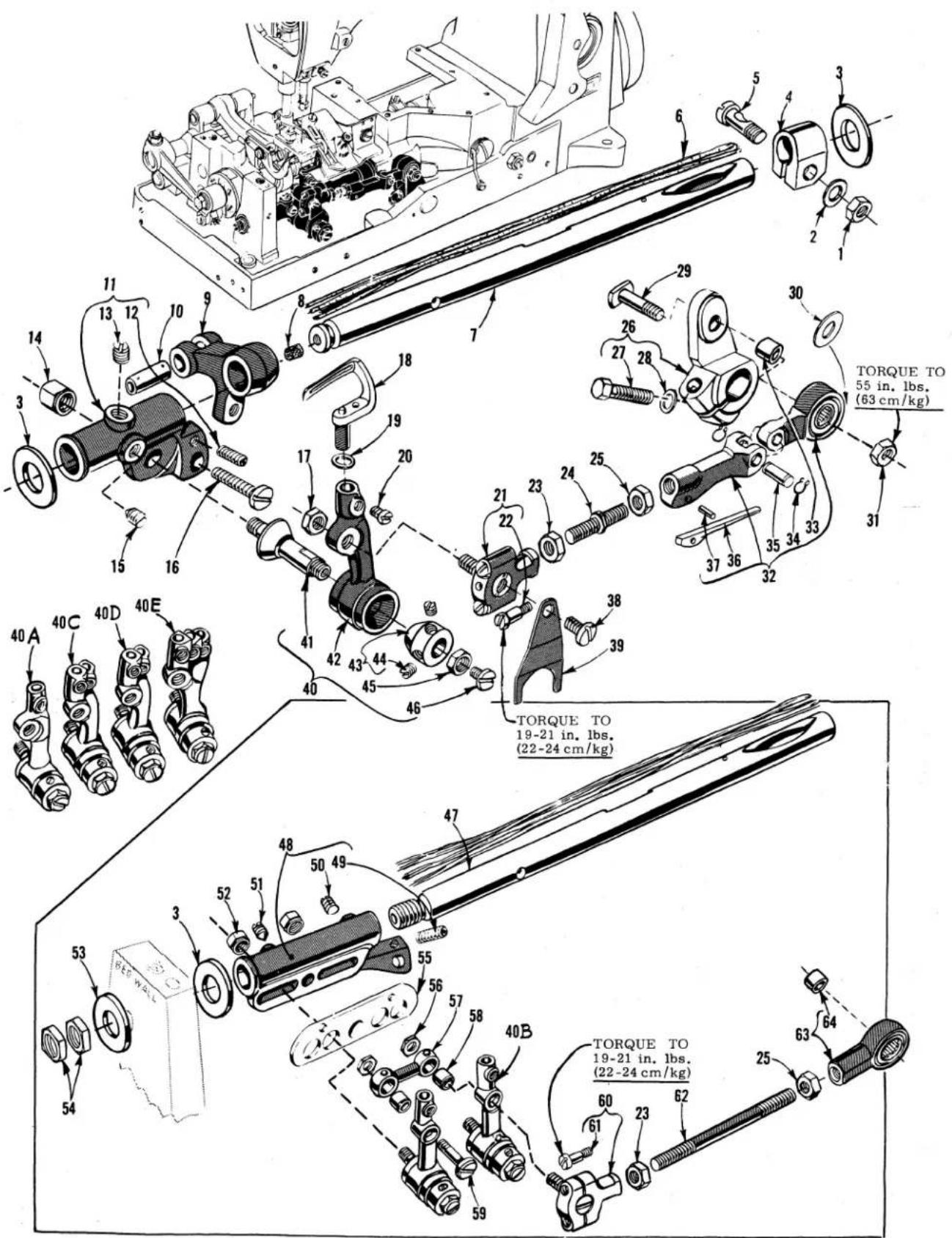
TORQUE TO 55 in. lbs. (63 cm/kg) TORQUE TO 19-21 in. lbs. (22-24 cm/kg) TORQUE TO 19-21 in. lbs. (22-24 cm/kg)LOOPER ROCKER AND CONNECTING ROD PARTS
| Ref. No. | Part No. | Description | Am Re |
| 1 | 18 | Nut, for all Styles except 56700 J | -1 |
| 2 | 51216 N | Washer, for all Styles except 56700 J | -1 |
| 3 | 51244 L | Thrust Washer | -2 |
| 4 | 51244 N | Looper Rocker Shaft Clamp, for all Styles except 56700 J | -1 |
| 5 | 55244 G | Looper Rocker Shaft Collar Stud, for all Styles except 56700 J | -1 |
| 6 | W03 | Columbia Wool Yarn (4 strands - 8 inches long) | -1 |
| 7 | 56344 | Looper Rocker Shaft, for all Styles except 56700 J | -1 |
| 8 | C067 E | Cork Plug | -1 |
| 9 | 56344 B | Looper Rocker Shaft Arm | -1 |
| 10 | 51236 A | Looper Avoid Link Pin | -1 |
| 11 | 56344 C | Looper Rocker Frame, for all Styles except 56700 J | -1 |
| 12 | 719 | Stop Screw | -1 |
| 13 | 98 | Screw | -1 |
| 14 | 51246 | Looper Rocker Stud Nut, for all Styles except 56700 J | -1 |
| 15 | 96 | Screw | -1 |
| 16 | 22874 | Looper Rocker Frame Lock Screw | -1 |
| 17 | 18 | Nut, for all Styles except 56700 J | -1 |
| 18 | Looper (See Page 45) | -1 | |
| 19 | Looper Collar (See Page 45) | -1 | |
| 20 | 73 | Screw | 1,2,3 |
| 21 | 57841 | Looper Connecting Rod Ball Joint, left, for all Styles except 56700 J | -1 |
| 22 | 22729 C | Screw | -2 |
| 23 | 269 | Nut, left hand thread | -1 |
| 24 | 51240 D | Looper Connecting Rod, for all Styles except 56700 J and Class 56400 | -1 |
| - | 57840 | Looper Connecting Rod, for Class 56400 | -1 |
| 25 | 18 | Nut, right hand thread | -1 |
| 26 | 56342 E | Looper Drive Lever, marked "D" | -1 |
| 27 | 22882 C | Screw | -1 |
| 28 | 51242 M | Washer | -1 |
| 29 | 52942 R | Looper Lever Stud | -1 |
| 30 | 20 | Washer | -1 |
| 31 | 18 | Nut | -1 |
| 32 | 56341 M | Looper Connecting Rod Jointed Section Assembly, right, for all Styles except 56700 J- | -1 |
| 33 | 56341 F | Ferrule | -1 |
| 34 | 660-310 | Truarc Ring | -2 |
| 35 | 56341 E | Hinge Pin | -1 |
| 36 | 56341 G | Spring | -1 |
| 37 | 50-458 Blk. | Spring Pin | -1 |
| 38 | 87 U | Screw | -1 |
| 39 | 56393 J | Looper Connecting Rod Ball Joint Oiler, left | -1 |
| 40 | Looper Rocker Assembly (See Chart Below) | -1 | |
| 41 | 51745 | Looper Rocker Cone Stud | -1 |
| 42 | Looper Rocker (See Chart Below) | -1 | |
| 43 | 15465 F | Looper Rocker Cone | -1 |
| 44 | 88 | Screw | -2 |
| 45 | 258 A | Lock Nut | -1 |
| 46 | 22829 | Lock Nut Screw | -1 |
| 47 | 56744 A | Looper Rocker Shaft, for Style 56700 J | -1 |
| 48 | 56744 | Looper Rocker Frame, for Style 56700 J | -1 |
| 49 | 719 | Stop Screw | -1 |
| 50 | 98 | Set Screw | -1 |
| 51 | 96 | Spot Screw | -1 |
| 52 | 1280 | Looper Rocker Stud Nut, for Style 56700 J | -2 |
| 53 | 56751 | Looper Rocker Shaft Thrust Washer, left, for Style 56700 J- | -1 |
| 54 | 51170 D | Nut, for Style 56700 J | -2 |
| 55 | 56772-56 | Looper Rocker Spacing Plate, for No. 56 gauge, Style 56700 J | -1 |
| - | 56772-64 | Looper Rocker Spacing Plate, for No. 64 gauge, Style 56700 J | -1 |
| 56 | 14077 | Nut, for Style 56700 J | -2 |
| 57 | 51770-56 | Looper Rocker Link, for No. 56 gauge, Style 56700 J | -1 |
| - | 51770-64 | Looper Rocker Link, for No. 64 gauge, Style 56700 J | -1 |
| 58 | 51771 | Looper Rocker Link Ferrule, for Style 56700 J | -2 |
| 59 | 22835 | Screw, for Style 56700 J | -1 |
| 60 | 57841 A | Looper Connecting Rod Ball Joint, left, for Style 56700 J | -1 |
| 61 | 22729 C | Screw | -2 |
| 62 | 41047 | Looper Connecting Rod, for Style 56700 J | -1 |
| 63 | 29476 LV | Looper Connecting Rod Assembly, right, for Style 56700 J | -1 |
| 64 | 56341 F | Ferrule | -1 |
| Ref. No. | Ref. No. 40 Assembly | Ref. No. 42 Rocker | I. D. Mark | For Machines | Amt. Req. |
| 40A | 29192 V | 56313 | S | Classes 56200, 56300 | 1 |
| 40B | 29192 X | 56713 | V | Class 56700 | 2 |
| 40C | 29192 W | 56413 | U | Class 56400 | 1 |
| 40D | 29192 AA | 56513 | X | Class 56500 | 1 |
| 40E | 29192 Y | 56913 | Z | Styles 56900 H, P | 1 |
| - | - | 56913 A | AB | Styles 56900 J, R | 1 |

text_image
RIGHT SIDE OF MAIN SHAFT HEAD TO BE SET .045 INCH (1.14 mm) FROM BED CASTING TORQUE TO 19-21 in. lbs. (22-24 cm/kg) TORQUE TO 19-21 in. lbs. (22-24 cm/kg)MAIN SHAFT, TAKE-UPS AND FEED DRIVING PARTS
| Ref.No. | PartNo. | Description | Amt.Req. |
| 1 | 29476 MJ | Feed Rocker Arm and Feed Crank Link Sub-Assembly | 1 |
| 2 | 55235 E | Nut- | 1 |
| 3 | 6042 A | Washer | 1 |
| 4 | 55235 D | Locking Stud | 1 |
| 5 | 77 | Screw, for link pin | 1 |
| 6 | 56336 B | Feed Crank Link | 1 |
| 7 | 56336 C | Feed Crank Link Ferrule | 1 |
| 8 | 51054 | Feed Crank Link Pin | 1 |
| 9 | 666-149 | Oil Wick | 1 |
| 10 | 269 | Nut, left thread | 1 |
| 11 | 21657 E | Washer | 1 |
| 12 | 22525 A | Screw | 4 |
| 13 | 56322 C | Main Shaft Head Plate | 1 |
| 14 | 22798 C | Screw | 1 |
| 15 | 56336 | Feed Crank Stud, marked "A" | 1 |
| 16 | 660-269 B | Quad Ring | 1 |
| 17 | 56336 D | Feed Crank Stud Insert | 1 |
| 18 | 22543 A | Stitch Regulating Screw | 1 |
| 19 | 56122 A | Main Shaft, for all Styles except 56700 J | 1 |
| - | 56722 E | Main Shaft, for Style 56700 J | 1 |
| 20 | 56322 B | Gasket | 1 |
| 21 | 22891 B | Oil Flow Regulating Screw | 1 |
| 22 | 29476 NM-062 | Feed Lift Eccentric Assembly, for Styles 56200 H,K,R,S; 56300 U,X; 56700 J and Class 56400 | 1 |
| - | 29476 NM-080 | Feed Lift Eccentric Assembly, for Styles 56200 L,W; 56500 A,B,C,J,U, 56900 H,J,P and 56300 except Styles 56300 H,M,U,X | 1 |
| - | 29476 NM-096 | Feed Lift Eccentric Assembly, for Styles 56300 H,M; 56500 R; 56900 R | 1 |
| 23 | 22894 AA | Spot Screw | 1 |
| 24 | 77 | Screw, for link pin | 1 |
| 25 | 39543 N | Thrust Washer, for feed bar | 2 |
| 26 | 29476 NM-054 | Looper Avoid Eccentric Assembly, for Class 56400 | 1 |
| - | 29476 NM-072 | Looper Avoid Eccentric Assembly, for Styles 56200 L, 56300 W,Classes 56500 and 56900 | 1 |
| - | 29476 NM-062 | Looper Avoid Eccentric Assembly, for Styles 56200 H,K,R,S: 56300 E,F,G,N,R,U,X,AH,AL; 56700 J | 1 |
| - | 29476 NM-080 | Looper Avoid Eccentric Assembly, for Styles 56200 W; 56300 H,M | 1 |
| 27 | 22894 AA | Spot Screw | 1 |
| 28 | 77 | Screw, for link pin | 1 |
| 29 | 56323 | Looper Thread Take-up, for Styles 56200 L,W and Classes 56300, 56500 and 56900 | 1 |
| 29 A | 56423 | Looper Thread Take-up, for Styles 56200 H,K,R,S and Class 56400 | 1 |
| 29 B | 56723 | Looper Thread Take-up, for Style 56700 J | 1 |
| 30 | 22764 C | Spot Screw | 1 |
| 31 | 22580 D | Set Screw | 1 |
| 32 | 56334 N | Feed Bar, for all Styles except 56300 N,U,X,AH | 1 |
| 32 A | 56334 P | Feed Bar, for Styles 56300 N,U,X,AH | 1 |
| 33 | 56334 L | Feed Dog Holder | 1 |
| 34 | 22863 C | Feed Dog Holder Adjusting Screw | 1 |
| 35 | 6042 A | Feed Dog Holder Washer | 1 |
| 36 | 258 A | Nut | 1 |
| 37 | 22637 P-24 | Feed Dog Height Adjusting Screw | 1 |
| 38 | 22651 CB-4 | Screw | 1 |
| 39 | 56335 L | Feed Rocker Shaft | 1 |
| 40 | 56335 D | Feed Rocker Shaft Collar | 1 |
| 41 | 98 | Screw | 2 |
| 42 | 56334 B | Feed Bar Shaft | 1 |
| 43 | 56335 G | Feed Rocker | 1 |
| 44 | 22651 CD-4 | Screw | 2 |
| 45 | 660-438 | Retaining Ring | 1 |
| 46 | 41391 | Washer | 1 |
| 47 | 61341 J | Feed Bar Washer | 2 |
| 48 | 22834 A | Needle Guard Adjusting Screw | 1 |
| 49 | Needle Guard (See Page 43) | 1 | |
| 50 | 22801 | Screw | 1 |
| 51 | 22875 H | Screw, for needle guard | 1 |
| 52 | 61434 G | Washer | 1 |
| 53 | 22528 | Screw, for feed dog | 1 |
| 54 | Feed Dog (See Pages 47,49,51,55,57,59,61,63,65)- | 1 | |
| 55 | 51236 A | Link Pin | 1 |
text_image
Technical diagram of a mechanical assembly with numbered components and exploded view, likely for assembly or maintenance.
text_image
Technical diagram of a mechanical assembly with numbered parts, likely a valve or clamp mechanism.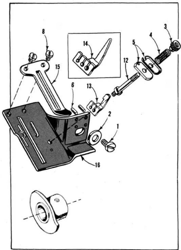
text_image
Technical diagram of a mechanical assembly with numbered parts and an inset view of a tool or component
text_image
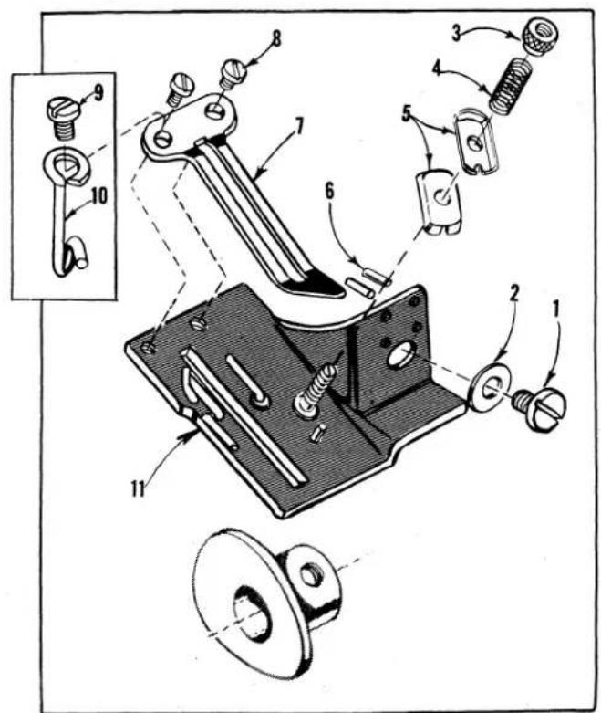
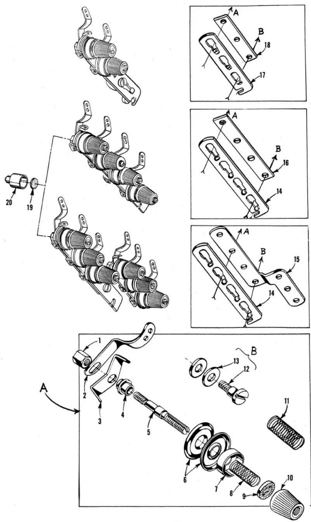
Technical diagram of a mechanical assembly with numbered parts, likely a valve or clamp mechanism.LOOPER THREAD TAKE-UP PARTS AND THUMBSCREW ADJUSTABLE
FRAME NEEDLE THREAD EYELET ASSEMBLY
| Ref.No. | PartNo. | Description | Amt.Req. |
| 1 | 22528 | Screw - - - - - - - - - - - - - - - - - - - - - - - - - - - - - - - - - - - - - - - - - - - - - - - - - - - - - - - - - - - - - - - - - - - - - - - - - - - - - - - - - - - - - - - - - - - - - - - - - - - - | 1 |
| 2 | 21657 E | Washer - - - - - - - - - - - - - - - - - - - - - - - - - - - - - - - - - - - - - - - - - - - - - - - - - - - - - - - - - - - - - - - - - - - - - - - - - - - - - - - - - - - - - - - - - - - - - - - - - - - | |
| 3 | 51959 D | Tension Nut - - - - - - - - - - - - - - - - - - - - - - - - - - - - - - - - - - - - - - - - - - - - - - - - - - - - - - - - - - - - - - - - - - - - - - - - - - - - - - - - - - - - - - - - - - - - - - - - - - - | |
| 4 | 51959 K | Tension Spring - - - - - - - - - - - - - - - - - - - - - - - - - - - - - - - - - - - - - - - - - - - - - - - - - - - - - - - - - - - - - - - - - - - - - - - - - - - - - - - - - - - - - - - - - - - - - - - - - - - 1 | |
| 5 | 51959 B | Tension Disc - - - - - - - - - - - - - - - - - - - - - - - - - - - - - - - - - - - - - - - - - - - - - - - - - - - - - - - - - - - - - - - - - - - - - - - - - - - - - - - - - - - - - - - - - - 2 | |
| 6 | 50-216 Blk. | Dowel Pin - - - - - - - - - - - - - - - - - - - - - - - - - - - - - - - - - - - - - - - - - - - - - - - - - - - - - - - - - - - - - - - - - - - - - - - - - - - - - - - - 2 | |
| 7 | 52804 A | Cast-off Plate, for all Styles, except 56700 J- 1 | |
| 8 | 28 | Screw, for all Styles, except 56300 E,F,G,N,R,U,X,AH,AL | 2 |
| U,X,AH,AL | 2 | ||
| - | 28 | Screw, for Styles 56300 E,F,G,N,R,U,X,AH,AL | - 1 |
| 9 | 22768 | Screw, for Styles 56300 E,F,G,N,R,U,X,AH,AL | - 1 |
| 10 | 56358 E | Looper Thread Guide Eyelet, for Styles | |
| 56300 E,F,G,N,R,U,X,AH,AL | - 1 | ||
| 11 | 51557 | Take-up Shield, for Classes 56200, 56300 | - 1 |
| 12 | 51492 | Tension Post, for Classes 56400, 56500, 56700, | |
| 56900 | - 1 | ||
| 13 | 51459 A | Looper Thread Guide, for Classes 56400, 56500, | |
| 56700 | - 1 | ||
| 14 | 51959 J | Looper Thread Guide, for Class 56900 | - 1 |
| 15 | 52804 A | Cast-off Plate, for all Styles, except 56700 J- 1 | |
| 16 | 51457 A | Take-up Shield, for Classes 56400, 56500, | |
| 56900 | - 1 | ||
| 17 | 51704 | Cast-off Plate, for Style 56700 J | - 1 |
| 18 | 51757 B | Take-up Shield, for Style 56700 J | - 1 |
| 19 | 29476 MY | Thumbscrew Adjustable Frame Needle Thread Eyelet Assembly, for Styles 56300 E,F,G,N,R,U,X,AH, | |
| AL | - 1 | ||
| 20 | 56304 | Adjusting Plate | - 1 |
| 21 | 56358 B | Guide Block | - 1 |
| 22 | 56358 C | Guide Washer | - 1 |
| 23 | 158 B | Eyelet | - 1 |
| 24 | 98 A | Screw | - 1 |
| 25 | 56358 D | Washer | - 1 |
| 26 | 22837 | Screw | - 1 |
| 27 | 20 | Washer | - 1 |
| 28 | 22848 | Screw | - 1 |
DISC THREAD TENSION PARTS
| Ref.No. | PartNo. | Description | AMOUNT REQUIRED | |||
| OneNeedleMachine | TwoNeedleMachine | ThreeNeedleMachine | ||||
| 1 | 43266 | Nut | 1 | 2 | 5 | |
| 2 | 51491 C | Lead-in Guide | 2 | 4 | 6 | |
| 3 | 51292 D | Tension Thread Eyelet | 2 | 4 | 6 | |
| 4 | 51292 A | Ferrule | 2 | 4 | 6 | |
| 5 | 56392 E | Tension Post | 2 | 4 | 6 | |
| 6 | 109 | Tension Disc | 4 | 8 | 12 | |
| 7 | 56392 F | Tension Spring Shield | 2 | 4 | 6 | |
| 8 | - | Needle Thread Tension Spring | (See Chart Below) | |||
| 9 | 39592 AK | Tension Spring Ferrule | 2 | 4 | 6 | |
| 10 | 39592 Z | Tension Nut | 2 | 4 | 6 | |
| 11 | - | Looper Thread Tension Spring | (See Chart Below) | |||
| 12 | 22598 C | Screw | 1 | - | 1 | |
| 13 | 80557 | Washer | 2 | - | 2 | |
| Ref.No. | PartNo. | Description | Amt.Req. | |||
| 14 | 21657-4 | Tension Disc Separator, for Single needle machine Styles 56300 E,F,G,N,R,U,X,AH; Two and Three needle machines - - - - - - - - - - - - - - - - - - - - - - - - - - - - - - - - - - - - - - - - - - - - - - - - - - - - - - - - - - - - - - - - - - - - - - - - - - - - - - - - - - - - - - - - - - - - - - - - - - - - | ||||
| 15 | 51992 A | Tension Post Support, for Three needle machines - - - - - - - - - - - - - - - - - - - - - - - - - - - - - - - - - - - - - - - - - - - - - - - - - - - - - - - - - - - - - - - - - - - - - - - - - - - - - - - - - - - - - - - - - - - - - - - - | ||||
| 16 | 56382 X | Tension Post Support, for Single needle machine Styles 56300 E,F,G,N,R,U,X,AH and Two needle machines - - - - - - - - - - - - - - - - - - - - - - - - - - - - - - - - - - - - - - - - - - - - - - - - - - - - - - - - - - - - - - - - - - - - - - - - - - - - - - - - - - - - - - - - - - - - - - - - - | ||||
| 17 | 21657-3 | Tension Disc Separator, for Single needle machine Styles 56200 H,K,L,R,S,W,56300 H,M,W,AL - - - - - - - - - - - - - - - - - - - - - - - - - - - - - - - - - - - - - - - - - - - - - - - - - - - - - - - - - - - - - - - - - - - - - - - - - - - - - - - - - - - - - - - - - - - - - - - - - - - | ||||
| 18 | 52892 | Tension Post Support, for Single needle machine Styles 56200 H,K,L,R,S,W,56300 H,M,W,AL - - - - - - - - - - - - - - - - - - - - - - - - - - - - - - - - - - - - - - - - - - - - - - - - - - - - - - - - - - - - - - - - - - - - - - | ||||
| 19 | 59292 A | Felt Washer, for auxiliary tension post support- - - - - - as requiredAuxiliary Tension Post Support, for Single needle machine Styles56300 E,F,G,N,R,U,X,AH; Two and Three needle machines- - - - - - - - - - - - - - - - - - - - - - - - - - - - - - - - - - - - - - - - - - - - - - - - - - - - - - - - - - - - - - - - - - - - - - - - - - - - - - - - - - - - - - - - - - - - - - - - - - - - – – – – – – – – – – – – – – – – – – – – – – – – – – – – – – – – – – – – – – – – – – – – – – – – – – – – – – – – – – – – – – – – – – – – – – – – – – – – – – – – – – – – – – – – – – – – – – – – – – – –– – – – – – – – – – – – – – – – – – – – – – – – – – – – – – – – – – – – – – – – – – – – – – – – – – – – – – – – – – – – – – – – – – – – – – – – – – – – – – – – – – – – – – – – – – – – – – – – – – – – — – – – – – – – – – – – – – – – – – – – – – – – – – – – – – – – – – – – – – – – – – – – – – – – – – – – – – – – – – – – – – – – – – – – – – – – – – – – – – – – – – – – – – – – – – – – – – – – – – – – | ||||
TENSION SPRING CHART
| Ref.No. | PartNo. | Description | Machine Style | Amt.Req. |
| 8 | 51292 F-5 | Needle Thread Tension Spring | 56200 H, K, R, S56400 D,P,R,S,T,W,X; 56700 J | 12 |
| 8 | 51292 F-8 | Needle Thread Tension Spring | 56200 L; 56300 E, F, G, M, N, R,U, W, X, AH, AL56500 A, B, C, J, R, U,56900 H, J, P. R | 123 |
| 8 | 51292 F-14 | Needle Thread Tension Spring | 56200 W, 56300 H | 1 |
| 11 | 51292 F-1 | Looper Thread Tension Spring | 56200 H, K, R, S56400 D, P, R, S, T, W, X;56700 J | 12 |
| 11 | 51292 F-2 | Looper Thread Tension Spring | 56200 L, W, 56300 E, F, G, H, M,N, R, U, W, X, AH, AL56500 A, B, C, J, R, U56900 H, J, P, R | 123 |
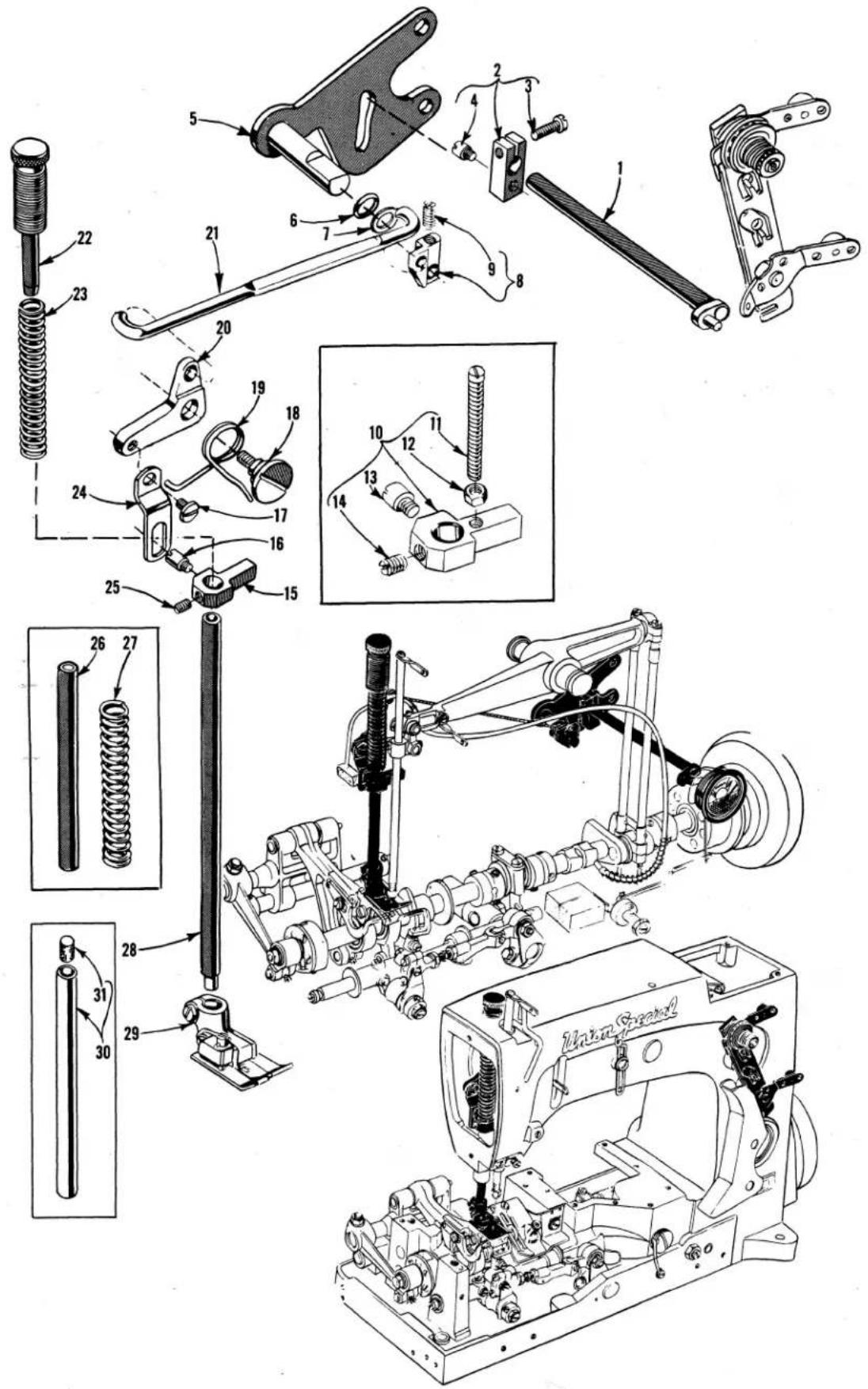
text_image
Technical diagram of a mechanical assembly with numbered parts and exploded views, including spring, chain, and motor components.TENSION AND LIFTER LEVER PARTS
| Ref.No. | PartNo. | Description | Amt.Req. |
| 1 | 21657 W | Tension Release and Lifter Lever Shaft | 1 |
| 2 | 21657 Y | Tension Release and Lifter Lever Shaft Connection | 1 |
| 3 | 22596 | Screw | 1 |
| 4 | 402 | Screw | 1 |
| 5 | 51283 H | Lifter Lever | 1 |
| 6 | 660-207 | Oil Seal Ring | 1 |
| 7 | 39552 C | Washer | 1 |
| 8 | 53783 N | Lifter Lever Connection | 1 |
| 9 | 22537 | Screw | 1 |
| 10 | 56357 A | Presser Bar Connection and Guide, for Styles 56300 F, R- | 1 |
| 11 | 22840 C | Screw | 1 |
| 12 | 51430 F | Nut | 1 |
| 13 | 402 | Screw | 1 |
| 14 | 531 | Screw | 1 |
| 15 | 51257 M | Presser Bar Connection and Guide, for all Styles except 56300 F, R- | 1 |
| 16 | 402 | Screw- | 1 |
| 17 | 22758 C | Screw- | 1 |
| 18 | 22557 G | Screw- | 1 |
| 19 | 56383 D | Lifter Lever Bell Crank Spring | 1 |
| 20 | 56383 AA | Lifter Lever Bell Crank | 1 |
| 21 | 56383 AB | Lifter Lever Connecting Rod- | 1 |
| 22 | 56356 | Presser Spring Regulator, for all styles except 56900 R- | 1 |
| - | 52889 A | Presser Spring Regulator, for Style 56900 R- | 1 |
| 23 | 51256 C | Presser Spring, for Styles 56200 H, K, R, S, 56300 U, X- | 1 |
| 24 | 56383 A | Lifter Lever Link- | 1 |
| 25 | 531 | Screw- | 1 |
| 26 | 51957 E | Presser Bar, for Styles 56900 J, P | 1 |
| 27 | 53787 | Presser Spring, for Styles 56200 L, W, 56300 E, F, G, H, M, N, R, W, AH, AL and Classes 56400, 56500, 56700, 56900 | 1 |
| 28 | 51257 K | Presser Bar, marked "A", for all Styles except 56900 J, P, R | 1 |
| 29 | Presser Foot (See Pages 47, 49, 51, 53, 55, 57, 59, 61, 63, 65) | 1 | |
| 30 | 51957 D | Presser Bar, for Style 56900 R | 1 |
| 31 | C067 D | Cork- | 1 |
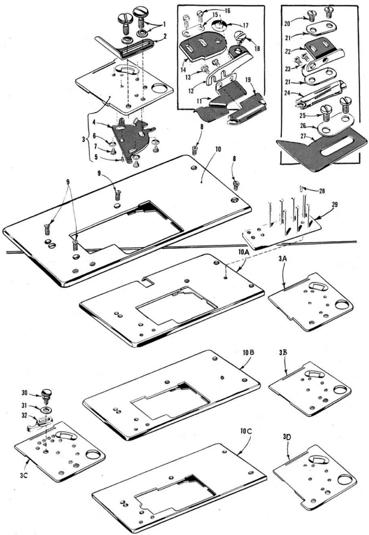
text_image
Exploded view diagram of a device's internal components with numbered parts and exploded viewsCLOTH PLATES, CLOTH PLATE COVERS, EDGE GUIDES AND BINDERS
| Ref.No. | PartNo. | Description | Amt.Req. |
| 1 | 25 | Screw, for edge guide - - - - - - - - - - - - - - - - - - - - - - - - - - - - - - - - - - - - - - - - - - - - - - - - - - - - - - - - - - - - - - - - - - - - - - - - - - - - - - - - - - - - - - - - - - - - - - - - - - - - | 2 |
| 2 | 24 | Edge Guide, for Styles 56200 H, S, 56500 A, B, C, U and Class 56300 except 56300 H, M - - - - - - - - - - - - - - - - - - - - - - - - - - - - - - - - - - - - - - - - - - - - - - - - - - - - - - - - - - - - - - - - - - - - - - - - - - - - - - - - - - - - - - - - - - - - - - - - - - - | |
| 3 | 56381-212 | Cloth Plate Cover, 3 5/16 inches wide, for Styles 56300 F, R, X, AH - - - - - - - - - - - - - - - - - - - - - - - - - - - - - - - - - - - - - - - - - - - - - - - - - - - - - - - - - - - - - - - - - - - - - - - - - - - - - - - - - - - - - - - - - - - - - - - - - - - 1 | |
| 3A | 56381-222 | Cloth Plate Cover, 3 15/32 inches wide, for Styles 56200 R, S, 56300 E, G, N, U, W - - - - - - - - - - - - - - - - - - - - - - - - - - - - - - - - - - - - - - - - - - - - - - - - - - - - - - - - - - - - - - - - - - - - - - - - - - - - - - - - - - - - - - - - - - - - - - - - - - - | |
| 3B | 56381-207 | Cloth Plate Cover, 3 15/64 inches wide, for Styles 56300 H, AL, and Classes 56400, 56500, 56900 except 56400 R, S-48 - - - - - - - - - - - - - - - - - - - - - - - - - - - - - - - - - - - - - - - - - - - - - - - - - - - - - - - - - - - - - - - - - - - - - - - - - - - - - - - - - - - - - - - - - - - - - - - - - - - – 1 | |
| 56381 C-207 | Cloth Plate Cover, 3 15/64 inches wide, for Styles 56200 H, K, L, 56300 M - - - - - - - - - - - - - - - - - - - - - - - - - - - - - - - - - - - - - - - - - - - - - - - - - - - - - - - - - - - - - - - - - - - - - - - - - - - - - - - - - - - - - - - - - - - - - - - - - - –1 | ||
| 3C | 56381 E-207 | Cloth Plate Cover, 3 15/64 inches wide, for Style 56200 W - - - - - - - - - - - - - - - - - - - - - - - - - - - - - - - - - - - - - - - - - - - - - - - - - - - - - - - - - - - - - - - - - - - - - - - - - - - - - - - - - - - - - - - - - - - - - - - - - - – | 1 |
| 3D | 56381-187 | Cloth Plate Cover, 2 59/64 inches wide, for Styles 56400 R, S-48, 56700 J - - - - - - - - - - - - - - - - - - - - - - - - - - - - - - - - - - - - - - - - - - - - - - - - - - - - - - - - - - - - - - - – 1 | |
| 4 | 51281 AC | Cloth Plate Cover Spring - - - - - - - - - - - - - - - - - - - - - - - - - - - - - - - - - - - - - - - - – 1 | |
| 5 | 22845 B | Screw - - - - - - - - - - - - - - - - - - - - - - - - - - - – 1 | |
| 6 | 35772 H | Spring Washer - - - - - - - - - - - - - - - - - - - - - - - – 3 | |
| 7 | 22760 A | Screw - - - - - - - - - - - - - - – 3 | |
| 8 | 22839 C | Screw, for cloth plate - - - - - - - – 2 | |
| 9 | 22526 C | Screw, for cloth plate - - - - - – 3 | |
| 10 | 56301 | Cloth Plate, for Styles 56200 R,S, 56300 E, F, G, R, W - - - - – 1 | |
| 10A | 56301 A | Cloth Plate, for Styles 56300 N, U, X, AH - - - - – 1 | |
| 10B | 56401 | Cloth Plate, for Styles 56200 H, K, L, W, 56300 H, M, AL and Classes 56400, 56500, 56900 except 56400 R, S-48 - - - - – 1 | |
| 10C | 56701 | Cloth Plate, for Styles 56400 R, S-48, 56700 J - - - - – 1 | |
| 11 | 23438 B | Body Fabric Lead-in Platform, for Styles 56200 L and 56300 M - - - 1 | |
| 12 | 23437 Y | Binder Swinging Bracket, for Styles 56200 L and 56300 M - - - 1 | |
| 13 | 90 | Screw, for binder - - - - – 2 | |
| 14 | 23437 B | Binder Swinging Bracket Support, for Styles 56200 L and 56300 M - 1 | |
| 15 | 23425 T | Clamping Plate, for Styles 56200 L and 56300 M - - - – 1 | |
| 16 | 22585 | Screw, for binder swinging bracket support - – 2 | |
| 17 | 12957 E | Spring Washer, for binder swinging bracket - – 1 | |
| 18 | 22735 | Screw, for binder swinging bracket - – 1 | |
| 19 | 23215 BG-5/8 | English Binder, uses selvage edge binding strip 5/8 inch wide, 5/32 inches capacity for body fabric, finsihes 5/16 inch wide, for Styles 56200 L and 56300 M - – – 1 | |
| 23215 BG-3/4 | English Binder, use 3/4 inch strip and finishes 3/8 inch, for Styles 56200 L and 56300 M - – – 1 | ||
| 23215 BG-7/8 | English Binder, uses 7/8 inch strip and finishes 7/16 inch, for Styles 56200 L and 56300 M - – – – – – – – – – – – – – – – – – – – – – – – – – – – – – – – – – – – – – – – – – – – – – – – – – – – – – – – – – – – – – – – – – – – – – – – – – – – – – – – – – – – – – – – – – – – – – – – – – – – – — | ||
| 20 | 90 | Screw, for binder support - – – – – – – – – – – – – – – – – – – – – – – – – – – – – – – – – – – – – – – – – – – – – – – – – – – – – – – – – – – – – – – – – – – – – – – – – – – – – – – – – – – – – – – – – – – – – – – – – – – — | 2 |
| 21 | 23425 T | Clamping Plate, for Style 56200 K - – – – – – – – – – – – – – – – – – – – – – – – – – – – – – – – – – – – – – – – – – – – – – – – – – – – – – – – – – – – – – – – – – – – – – – – – – – – – – – – – – – – – – – – – – – – – – – – – – – × | |
| 22 | 23322 AC | Binder Support, for Style 56200 K - – – – – – – – – – – – – – – – – – – – – – – – – – – – – – – – – – – – – – – – – – – – – – – – – – – – – – – – – – – – – – – – – – – – – – – – – – – – – – – – – – – – – – – – – × | |
| 23 | 90 | Screw, for binder - – – – – – – – – – – – – – – – – – – – – – – – – – – – – – – – – – – – – – – – – – – – – – – – – – – – – – – – – – – – – – – – – – × | |
| 24 | 23322 AB-3/4 | Cut Edge Binder, uses strip cut 3/4 inch wide, finishes 7/32 inch wide, for Style 56200 K - – – – – – – – – – – – – – – – – – – – – – – – – – – – – – – – – – – – – – × | |
| 23322 AB-7/8 | Cut Edge Binder, uses strip cut 7/8 inch wide, finishes 1/4 inch wide, for Style 56200 K - – – – – – – – – – – – – – – – – – – – – – – – – – – – – – – – – – × | ||
| 23322 AB-1 | Cut Edge Binder, uses strip cut 1 inch wide, finishes 9/32 inch wide, for Style 56200 K - – – – – – – – – – – – – – – – – – – – – – × | ||
| 23322 AB-1 1/8 | Cut Edge Binder, uses strip cut 1 1/8 inch wide, finishes 11/32 inch wide, for Style 56200 K - – – – – – – – – – – – – – – × | ||
| 23322 AB-1 1/4 | Cut Edge Binder, uses strip cut 1 1/4 inch wide, finishes 13/32 inch wide, for Style 56200 K - – – – – – – – – – – × | ||
| 25 | 25 C | Screw, for body fabric lead-in platform - – – – – – – – – – – – – – – – – – – – – – – – – – – – – – – – – – – – – – – – – – – – – – – – – – – – – – – – – – – – – – – – – – – – – – – – – – – – – – – – – – – – – – – – – – – – – – – – – – – | |
| 26 | 23425 V | Washer Plate, for Style 56200 K - – – – – – – – – – – – – – – – – – – – – – – – – – – – – – – – – – – – – – – – – – – – – – – – – – – – – – – – – – – – – – – – – – – – – – – – – – – – – – – – – – – – – – – – × | |
| 27 | 23438 A | Body Fabric Lead-in Platform, for Style 56200 K - – – – – – – – – – – – – – – – – – – – – – – – – – – – – – – – – – – – × | |
| 28 | 90 | Screw, for pin tension - – – – – – – – – – – – – – – – – – – – – – – – – – – – – – – – – – – × | |
| 29 | 23439 A | Pin Tension, for binding on Styles 56200 K, 56200 L and 56300 M - — × | |
| 30 | 25 TB | Screw, for edge guide - – – – – – – – – – – – – – × | |
| 31 | 21657 E | Washer, for edge guide - — × | |
| 32 | 24 S | Edge Guide, for Style 56200 W - — × | |

text_image
Technical diagram showing exploded view of mechanical assembly with numbered components and directional arrows indicating assembly steps.NEEDLE BARS, NEEDLE HOLDERS AND NEEDLE GUARDS
| Ref.No. | PartNo. | Description | Amt.Req. | |
| 1 | 51217 C | Needle Bar, marked "CU", for Classes 56200, 56300 | - - - - - - - - - - - - - - - - - - - - - - - - - - - - - - - - - - - - - - - - - - - - - - - - - - - - - - - - - - - - - - - - - - - - - - - - - - - - - - - - - - - - - - - - - - - - - - - - - - - - - | 1 |
| 2 | 56 | Needle Clamp Nut, for Classes 56200, 56300 | - - - - - - - - - - - - - - - - - - - - - - - - - - - - - - - - - - - - - - - - - - - - - - - - - - - - - - - - - - - - - - - - - - - - - - - - - - - - - - - - - - - | |
| 3 | 56325 | Needle Guard, for Classes 56200, 56300 | - - - - - - - - - - - - - - - - - - - - - - - - - - - - - - - - - - - - - - - - - - - - - - - - - - - - - - - - - - - - - - - - - - - - - - - - - - - - - - - - - - | 1 |
| 4 | 22801 | Screw | - - - - - - - - - - - - - - - - - - - - - - - - - - - - - - - - - - - - - - - - - - - - - - - - - - - - - - - - - - - - - - - - - - - - - - - - - - - - - - - - - - - - - - - - - - - - - - - - - - | |
| 5 | 51417 C-6 | Needle Bar, marked "CV-6", for No. 6 gauge, Style 56400 P | - - - - - - - - - - - - - - - - - - - - - - - - - - - - - - - - - - - - - - - - - - - - - - - - - - - - - - - - - - - - - - - - - - - - - - - - - - - - - - - - - - - - - - - - - - - - - - - - - - | 11 |
| - | 51417 C-8 | Needle Bar, marked "CV-8", for No. 8 gauge, Styles 56400 P, T, W | - - - - - - - - - - - - - - - - - - - - - - - - - - - - - - - - - - - - - - - - - - - - - - - - - - - - - - - - - - - - - - - - - - - - - - - - - - - - - - - - - - - - - - - - - - - - - - - - - - | |
| - | 51417 C-10 | Needle Bar, marked "CV-10", for No. 10 gauge, Styles 56400 P, T, W, | - - - - - - - - - - - - - - - - - - - - - - - - - - - - - - - - - - - - - - - - - - - - - - - - - - - - - - - - - - - - - - - - - - - - - - - - - - - - - - - - - - - - - - - - - - - - - - - - - - 1 | |
| - | 51417 C-12 | Needle Bar, marked "CV-12", for No. 12 gauge, Styles 56400 D, P, T, W | - - - - - - - - - - - - - - - - - - - - - - - - - - - - - - - - - - - - - - - - - - - - - - - - - - - - - - - - - - - - - - - - - - - - - - - - - - - - - - - - - - - - - - - - - - - - - 1 | |
| - | Screw | Needle Bar, marked "CV-16", for No. 16 gauge, Styles 56400 D, P, T, W | - - - - - - - - - - - - - - - - - - - - - - - - - - - - - - - - - - - - - - - - - - - - - - - - - - - - - - - - - - - - - - - - - - - - - - - - - - - - - - - - - - 1 | |
| - | 51417 C-18 | Needle Bar, marked "CV-18", for No. 18 gauge, Style 56400 P | - - - - - - - - - - - - - - - - - - - - - - - - - - - - - - - - - - - - - - - - - - - - - - - - - - - - - - - - - 1 | |
| 6 | 50 J-16 | Stop Pin | - - - - - - - - - - - - - - - - - - - - - - - - - - - - - - - - - - - - - - - - - - - - - - - - - - - - - - - - - - - - - - - 1 | |
| 7 | 98 | Screw, for needle | - - - - - - - - - - - - - - - - - - - - - - - - - - - - - - - - - - - - - - - - - - - - - - - - - - - - - - 2 | |
| 8 | 51418-16 | Needle Holder, marked "D-16", for all gauges Styles 56400 D, P, T, W and No. 16 gauge, Style 56500 J | - - - - - - - - - - - - - - - - - - - - - - - - - - - - - - - - - - - - - - - - - - 1 | |
| 9 | 89 | Spot Screw | - - - - - - - - - - - - - - - - - - - - - - - - - - - - - - - - - - - - - - - - 1 | |
| 10 | 56425 | Needle Guard, for Class 56400, all gauges | - - - - - - - - - - - - - - - - - - - - - - - - - - - - - - - - - - - 1 | |
| 11 | 51417 D | Needle Bar, marked "DE", for Nos. 24, 26, 32, 48 gauges, Styles 56400 R, S, X | - - - - - - - - - - - - - - - - - - - - - - - 1 | |
| 12 | 50 J-40 | Stop Pin | - - - - - - - - - - - - - - - - - - - - - - - - - - 1 | |
| 13 | 51418 K-24 | Needle Holder, marked "L-24", for No. 24 gauge, Style 56400 X | - - - - - - - - - - - - - 1 | |
| - | 51418 K-26 | Needle Holder, marked "L-26", for No. 26 gauge, Style 56400 X | - 1 | |
| 14 | 51418 B-32 | Needle Holder, marked "D-32", for No. 32 gauge, Style 56400 S | - 1 | |
| 15 | 51418 D-48 | Needle Holder, marked "AC-48", for No. 48 gauge, Styles 56400 R, S | - 1 | |
| 16 | 56517 B-16 | Needle Bar, marked "ET", for No. 16 gauge, Style 56500 J | - 1 | |
| 17 | 50 J-16 | Stop Pin | - 1 | |
| 18 | 51418-16 | Needle Holder, marked "D-16", for No. 16 gauge, Style 56500 J and all gaugesStyle 56400 D, P, T, W | - 1 | |
| 19 | 56517 B-18 | Needle Bar, marked "EU", for No. 18 gauge, Style 56500 J, R | - 1 | |
| 20 | 50 J-16 | Stop Pin | - 1 | |
| 21 | 7018 E-5 | Needle Holder, marked "G-5", for No. 18 gauge, Styles 56500 J, R | - 1 | |
| 22 | 7040-6 | Thread Guide | - 1 | |
| 22A | 187 B | Screw | - 1 | |
| 23 | 56525 | Needle Guard, for Styles 56500 J, R all gauges | - 1 | |
| 24 | 29202 M-1 | Needle Bar Assembly, for 7 S.P.I., Styles 56500 B, U | - 1 | |
| - | 29202 N-1 | Needle Bar Assembly, for 10 S.P.I., Style 56500 C | - 1 | |
| 25 | 56517 D-1 | Needle Bar, marked "EK", for 7 S.P.I., Styles 56500 B, U | - 1 | |
| - | 56517 E-1 | Needle Bar, marked "EL", for 10 S.P.I., Style 56500 C | - 1 | |
| 26 | 50 J-16 | Stop Pin | - 1 | |
| 27 | 51518 G-1 | Needle Holder, marked "P-1", for 7 S.P.I., Styles 56500 B, U | - 1 | |
| - | 51518 C-1 | Needle Holder, marked "Q-1", for 10 S.P.I., Style 56500 C | - 1 | |
| 28 | 89 | Spot Screw | - 1 | |
| 29 | 88 B | Screw, for needle | - 1 | |
| 30 | 22729 | Screw, for needle | - 1 | |
| 31 | 56525 B | Needle Guard, for 7 S.P.I., Styles 56500 B, U | - 1 | |
| - | 56525 C | Needle Guard, for 10 S.P.I., Style 56500 C | - 1 | |
| 32 | 29202 L-1 | Needle Bar Assembly, for 5 S.P.I., Style 56500 A | - 1 | |
| 33 | 56517 C-1 | Needle Bar, marked "ES", for 5 S.P.I., Style 56500 A | - 1 | |
| 34 | 50 J-16 | Stop Pin | - 1 | |
| 35 | 56518 C-1 | Needle Holder, marked "AS", for 5 S.P.I., Style 56500 A | - 1 | |
| 36 | 89 | Spot Screw | - 1 | |
| 37 | 22743 | Screw, for needle | - 1 | |
| 38 | 22729 | Screw, for needle | - 1 | |
| 39 | 56525 A | Needle Guard, for 5 S.P.I.,-Style 56500 A | - 1 | |
| 40 | 51717 | Needle Bar, marked "AU", for Style 56700 J all gauges | - 1 | |
| 41 | 51718 A-56 | Needle Holder, marked "AB-56", for No. 56 gauge, Style 56700 J | - 1 | |
| - | 51718 A-64 | Needle Holder, marked "AB-64", for 64 gauge, Style 56700 J | - 1 | |
| 42 | 22894 P | Spot Screw | - 1 | |
| 43 | 98 | Screw, for needle | - 2 | |
| 44 | 51718 B-64 | Needle Stop and Thread Eyelet, for No. 64 gauge | - 2 | |
| - | 51718 B-56 | Needle Stop and Thread Eyelet, for No. 56 gauge | - 1 | |
| 45 | 22513 B | Screw, for No. 64 gauge | - 2 | |
| - | 605 A | Screw, for No. 56 gauge | - 2 | |
| 46 | 56725 | Needle Guard, for Style 56700 J all gauges | - 1 | |
| 47 | 56917 | Needle Bar, marked "EP-9", for Nos. 8, 9 gauges, Styles 56900 H, J, P, R | - 1 | |
| 48 | 50 J-26 | Stop Pin | - 1 | |
| 49 | 35818 N-8 | Needle Holder, marked "C-8", for No. 8 gauge, Style 56900 H | - 1 | |
| - | 35818 N-9 | Needle Holder, marked "C-9", for No. 9 gauge, Styles 56900 H, J, P, R | - 1 | |
| 50 | 22752 | Screw, for center needle | - 1 | |
| 51 | 22580 | Screw, for needle | - 2 | |
| 52 | 56925 | Needle Guard, for Class 56900 all gauges | - 1 | |
| 53 | 51917 A | Needle Bar, marked "DC", for No. 7 gauge, Style 56900 H | - 1 | |
| 54 | 50 J-26 | Stop Pin | - 1 | |
| 55 | 51918-7 | Needle Holder, marked "E-7", for No. 7 gauge, Style 56900 H | - 1 |
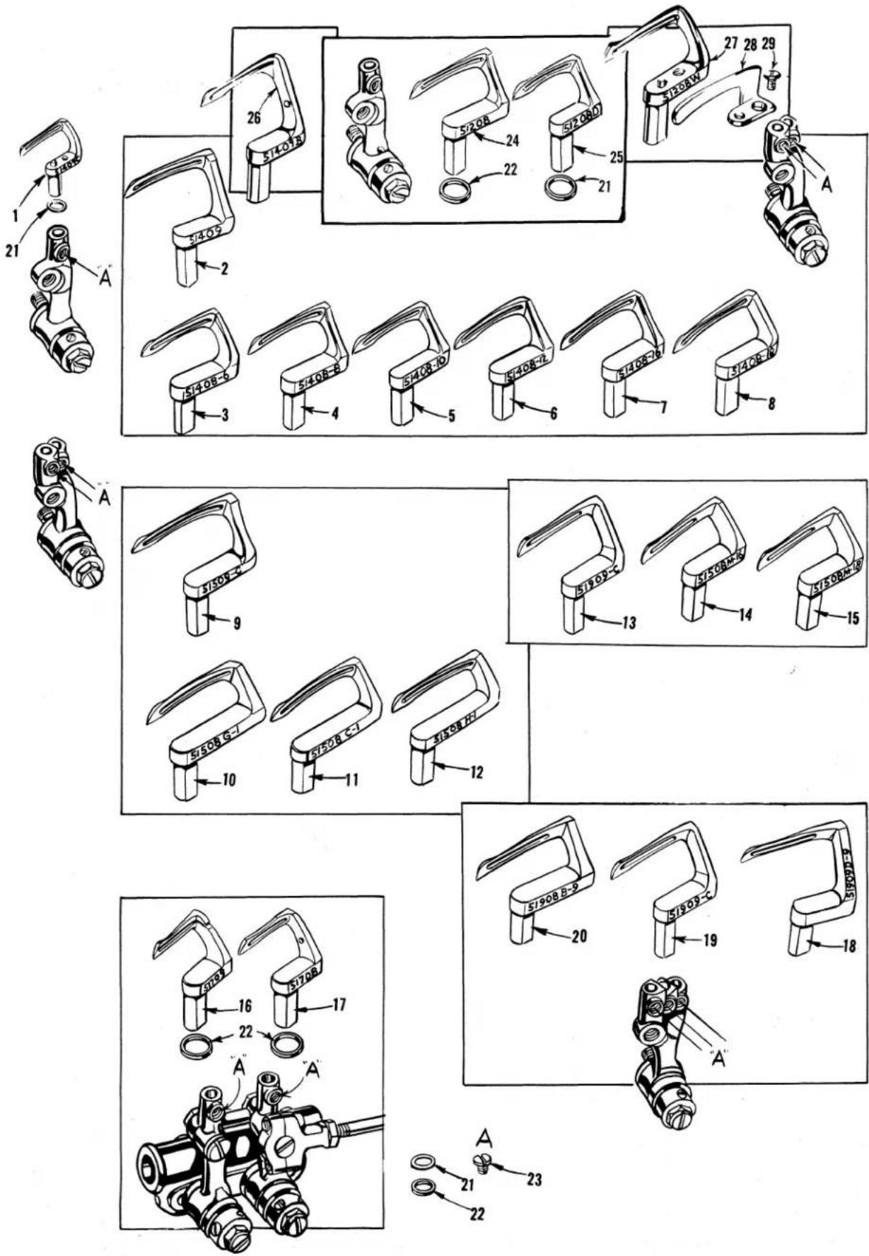
text_image
Technical diagram showing exploded and assembled views of mechanical components with numbered parts and labeled features.LOOPER, LOOPER COLLARS AND LOOPER NEEDLE GUARDS
| Ref.No. | PartNo. | Description | Amt.Req. | |
| 1 | 51409 C | Looper, for Style 56200 L and Class 56300 except Styles56300 H, M, AL - - - - - - - - - - - - - - - - - - - - - - - - - - - - - - - - - - - - - - - - - - - - - - - - - - - - - - - - - - - - - - - - - - - - - - - - - - - - - - - - - - - - - - - - - - - - - - - - - - - - | 1 | |
| 2 | 51409 | Looper, for Styles 56200 K, R - - - - - - - - - - - - - - - - - - - - - - - - - - - - - - - - - - - - - - - - - - - - - - - - - - - - - - - - - - - - - - - - - - - - - - - - - - - - - - - - - - - - - - - - - - - - - - - - - - - | ||
| 51409 | Looper, back, for Class 56400 all gauges, Styles 56400 R,S- - - - - - - - - - - - - - - - - - - - - - - - - - - - - - - - - - - - - - - - - - - - - - - - - - - - - - - - - - - - - - - - - - - - - - - - - - - - - - - - - - - - - - - - - - - - - - - - - - - - | |||
| 3 | 51408-6 | Looper, front, for No. 6 gauge, Style 56400 P - - - - - - - - - - - - - - - - - - - - - - - - - - - - - - - - - - - - - - - - - - - - - - - - - - - - - - - - - - - - - - - - - - - - - - - - - - - - - - - - - - - - - - - - - - - - - - - - - - - – | 1 | |
| 4 | 51408-8 | Looper, front, for No. 8 gauge, Styles 56400 P, T, W- - - - - - - - - - - - - - - - - - - - - - - - - - - - - - - - - - - - - - - - - - - - - - - - - - - - - - - - - - - - - - - - - - - - - - - - - - - - - - - - - - - - - - - - - - - - - - - - - - - – | ||
| 5 | 51408-10 | Looper, front, for No. 10 gauge, Styles 56400 P, T, W- - - - - - - - - - - - - - - - - - - - - - - - - - - - - - - - - - - - - - - - - - - - - - - - - - - - - - - - - - - - - - - - – | ||
| 6 | 51408-12 | Looper, front, for No. 12 gauge, Styles 56400 D, P, T, W- - | 1 | |
| 7 | 51408-16 | Looper, front, for No. 16 gauge, Styles 56400 D, P, T, W- - | 1 | |
| 8 | 51408-18 | Looper, front, for No. 18 gauge, Style 56400 P- - - - - - - - - - - - - - - - - - - - - - - - - - - - - - - - - - - - - - – | ||
| - | *51408-24 | Looper, front, for No. 24 gauge, Style 56400 X- - - - - - - - - - - - - - - - - - - - - - - – | ||
| - | *51408-26 | Looper, front, for No. 26 gauge, Style 56400 X- - - - - - - - - - - - - - - - – | ||
| - | *51408-32 | Looper, front, for No. 32 gauge, Style 56400 S- - - - - - - - - - – | ||
| - | *51408-48 | Looper, front, for No. 48 gauge, Styles 56400 R, S- - - - - - – – | ||
| 9 | 51509 C | Looper, back, for Styles 56500 A, B, C, U - - - - - - - - - – – – – – – – – – – – – – – – – – – – – – – – – – – – – – – – – – – – – – – – – – – – – – – – – – – – – – – – – – – – – – – – – – – – – – – – – – – – – – – – – – – – – – – – – – – – – – – – – – – – – — – – – – – – – – – – – – – – – – – – – – – – – – – – – – – – – – – – – – – – – – – – – – – – – – – – – – – – – – – – – – – – – – – – – – – – – – – – – – – – – – – – – – – – – – – – – – – – – – – – – _ | ||
| 10 | 51508 G-1 | Looper, front, for 7 S.P.I., Styles 56500 B, U- - - - - - - - - - – – – – – – – – – – – – – – – – – – – – – – – – – – – – – – – – – – – – – – – – – – – – – – – – – – – – – – – – – – – – – – – – – – – – – – – – – – – – – – – – – – – – – – – – – – _ | ||
| 11 | 51508 C-1 | Looper, front, for 10 S.P.I., Style 56500 C - - - - - - - - - - – – – – – – – – – – – – – – – – – – – – – – – – – – – – – – – – – – – – – – – – – – – – – – – – – – – – – – – – – – – – – – – – – – – – – – – – – – – – – – – – – – – – – – – – – – ~ | ||
| 12 | 51508 H-1 | Looper, front, for 5 S.P.I., Style 56500 A- - - - - - - - - - - - – – – – – – – – – – – – – – – – – – – – – – – – – – – – – – – – – – – – – – – – – – – – – – – – – – – – – – – – – – – – – – – – – – – – – – – – – – – – – – – – – – – – – – – – – _ | ||
| 13 | 51909 C | Looper, front, for Style 56300 M - - - - - - - - - - - - - - – – – – – – – – – – – – – – – – – – – – – – – – – – – – – – – – – – – – – – – – – – – – – – – – – – – – – – – – – – – – – – – – – – – – – – – – – – – – – – – – – – – – – – – – _ | ||
| 51909 C | Looper, back, for Styles 56500 J, R - - - - - - - - - – – – – – – – – – – – – – – – – – – – – – – – – – – – – – – – – – – – – – – – – – – – – – – – – – – – – – – – – – – – – – – – – – – – – – – – – – – – – – – – – – – – – – – – – – – — | |||
| 14 | 51508 M-16 | Looper, front, for No. 16 gauge, Style 56500 J- - - - - - - - – – – – – – – – – – – – – – – – – – – – – – – – – – – – – – – – – – – – – – – – – – – – – – – – – – – – – – – – – – – – – – – – – – – – – – – – – – – – – – – – – – – – – – – – – – – – — | ||
| 15 | 51508 M-18 | Looper, front, for No. 18 gauge, Styles 56500 J, R- - - - - - - – – – – – – – – – – – – – – – – – – – – – – – – – – – – – – – – – – – – – – – – – – – – – – – – – – – – – – – – – – – – – – – – – – – – – – – – – – – – – – – – – – – – – – – – – – – – – — | ||
| 16 | 51709 | Looper, left, for Style 56700 J all gauges- - - - - - - - - - - - — | 1 | |
| 17 | 51708 | Looper, right, for Style 56700 J all gauges- - - - - - - - - — | 1 | |
| 18 | 51909 D-9 | Looper, back, for No. 9 gauge, Styles 56900 H, J, P, R- - — | 1 | |
| 51909 D-8 | Looper, back, for No. 8 gauge, Style 56900 H- - - - - - - — | 1 | ||
| 51909 D-7 | Looper, back, for No. 7 gauge, Style 56900 H- - — | 1 | ||
| 19 | 51909 C | Looper, front, for Style 56300 M, middle looper for Class 56900and back looper for Styles 56500 J, R- — — — — — — — — — — — — — — — — — — — — — — — — — — — — — — — — — — — — — — — — — — — — — — — — — — — — — — — — — — — — — — — — — — — — — — — — — — — — — — — — — — — — — — — — — — — — — — — — — — — —— — — — — — — — — — — — — — — — — — — — — — — — — — — — — — — — — — — — — — — — — — — — — — — — — — — — — — — — — — — — — — — — — — — — — — — — — — — — — — — — — — — — — — — — — — — — — — — — — — — — | ||
| 20 | 51908 B-9 | Looper, front, for No. 9 gauge, Styles 56900 H, J, P, R- — | 1 | |
| 51908 B-8 | Looper, front, for No. 8 gauge, Style 56900 H- — — — — — — — — — — — — — — — — — — — — — — — — — — — — — — — — — — — — — — — — — — — — — — — — — — — — — — — — — — — — — — — — — — — — — — — — — — — — — — — — — — — — — — — — — — — — — — — — — — | |||
| 51908 B-7 | Looper, front, for No. 7 gauge, Style 56900 H- — — — — — — — — — — — — — — — — — — — — — — — — — — — — — — — — — — — — — — — — — — — — — — — — — — — — — — — — — — — — — — — — — — — — — — — — — — — — — — — — — — — — — — — — | |||
| 21 | 21210 A | Looper Collar, for Styles 56200 H, K, R, S and Class 56300except Styles 56300 G, H, M- — — — — — — — — — — — — — — — — — — — — — — — — — — — — — — — — — — — — — — — — — — — — — — — — — — — — — — — — — — — — — — — — — — — — — — — — — — — — — — — — — — — — — — — — — — — — — — — — — —— | ||
| 22 | 21210 | Looper Collar, for Styles 56200 L, W, 56300 H, M, 56700 J-1,2 | ||
| 23 | 73 | Screw, for looper — — — — — — — — — — — — — — — — — — — — — — — — — — — — — — — — — — — — — — — — — — — — — — — — — — — — — — — — — — — — — — — — — — — — — — — — — — — — — — — — — — — — — — — — — — — — — — — — — — — | 1 | |
| 24 | 51208 | Looper, for Style 56300 H- — — — — — — — — — — — — — — — — — — — — — — — — — — — — — — — — — — — — — — — — — — — — — — — — — — — — — — — — — — — — — — — — — — — — — — — — — — — — — — — — — — — — — — — — — — — — — — —— | ||
| 51208 D | Looper, for Styles 56200 H, S- — — — — — — — — — — — — — — — — — — — — — — — — — — — — — — — — — — — — — — — — — — — — — — — — — — — — — — — — — — — — — — — — — — — — — — — — — — — — — — — — — — — — — — — — — — — — — — — — — — | — | ||
| 51409 B | Looper, back, for Styles 56400 R, S- — — — — — — — — — — — — — — — — — — — — — — — — — — — — — — — — — — — — — — — — — — — — — — — — — — — — — — — — — — — — — — — — — — — — — — — — — — — — — — — — — — — — — — — — — — — — — — — — | |||
| 51208 W | Looper, for Styles 56200 W, 56300 AL- — — — — — — — — — — — — — — — — — — — — — — — — — — — — — — — — — — — — — — — — — — — — — — — — — — — — — — — — — — — — — — — — — — — — — — — — — — — — — — — — — — — — — — — — — — — — — — — — — — | |||
| 51210 | Looper Needle Guard, for Style 56200 W-———————— | |||
| 73 A | Screw, for looper needle guard-———————— | |||
*Not shown on picture plate.
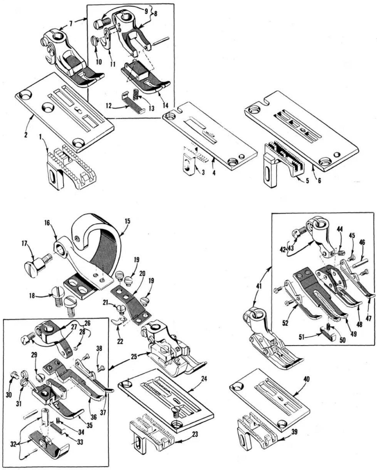
FEED DOGS, THROAT PLATES, PRESSER FEET AND TOP GRIP-FEED DRIVING PARTS
| Ref. No. | Part No. | Description | Amt. Req. | |
| 1 | 9205 E | Feed Dog, 16 teeth per inch, for Styles 56300 G, U - - - - - - - - - - - - - - - - - - - - - - - - - - - - - - - - - - - - - - - - - - - - - - - - - - - - - - - - - - - - - - - - - - - - - - - - - - - - - - - - - - - - - - - - - - - - - - - - - - - - | 1 | |
| 2 | 9224 E | Throat Plate, for Styles 56300 G, W - - - - - - - - - - - - - - - - - - - - - - - - - - - - - - - - - - - - - - - - - - - - - - - - - - - - - - - - - - - - - - - - - - - - - - - - - - - - - - - - - - - - - - - - - - - - - - - - - - - | ||
| 3 | 56305 AL | Feed Dog, 12 teeth per inch, for Style 56300 AL - - - - - - - - - - - - - - - - - - - - - - - - - - - - - - - - - - - - - - - - - - - - - - - - - - - - - - - - - - - - - - - - - - - - - - - - - - - - - - - - - - - - - - - - - - - - - - - - - - - | ||
| 4 | 56324 AL | Throat Plate, for Style 56300 AL - - - - - - - - - - - - - - - - - - - - - - - - - - - - - - - - - - - - - - - - - - - - - - - - - - - - - - - - - - - - - - - - - - - - - - - - - - - - - - - - - - - - - - - - - | ||
| 5 | 51205 R | Feed Dog, 16 teeth per inch, for Style 56200 H - - - - - - - - - - - - - - - - - - - - - - - - - - - - - - - - - - - - - - - - - - - - - - - - - - - - - - - - - - - - - - - - - - - - - - - - - - - - - - - - - - - - - - - - - - - - - - - - - - - | ||
| 6 | 56224 H | Throat Plate, for Style 56200 H - - - - - - - - - - - - - - - - - - - - - - - - - - - - - - - - - - - - - - - - - - - - - - - - - - - - - - - - - - - - - - - - - - - - - - - - - - - - - - - - - - - - - - - - - | ||
| 7 | 51320 M | Presser Foot, for Styles 56200 H, 56300 G, AL - - - - - - - - - - - - - - - - - - - - - - - - - - - - - - - - - - - - - - - - - - - - - - - - - - - - - - - - - - - - - - - - - - - - - - - - - - - - - - - - - - - - - - - - - - - - - - - - - - | ||
| 8 | 51330 AJ | Presser Foot Shank - - - - - - - - - - - - - - - - - - - - - - - - - - - - - - - - - - - - - - - - - - - - - - - - - - - - - - - - - - - - - - - - - - - - - - - - - - - - - - - - - - - - - | ||
| 9 | 91 | Screw - - - - - - - - - - - - - - - - - - - - - - - - - - - - - - - - - - - - - - - - - - - - - - - - - - - - - - - - - - - - - - - - - - - - - - - - - - | ||
| 10 | 187 B | Screw - - - - - - - - - - - - - - - - - - - - - - - - - - - - - - - - - - - - - - - - - - - - - - - - - - - - - - - - - - - - - - - - - - | ||
| 11 | 1741 B | Chain Cutting Knife - - - - - - - - - - - - - - - - - - - - - - - - - - - - - - - - - - - - - - - - - - - - - - - - - - - - - | ||
| 12 | 51330 AH | Yielding Section - - - - - - - - - - - - - - - - - - - - - - - - - - - - - - - - - - - - - - - - - - - - - - - - | ||
| 13 | 51330 W | Spring - - - - - - - - - - - - - - - - - - - - - - - - - - - - - - - - - - - - - - - - - - | ||
| 14 | 51330 AG | Presser Foot Bottom | - 1 | |
| 15 | 51334 A | Top Grip Feed Presser Foot Driving Arm, for Styles 56300 N, U, X, AH | - 1 | |
| 16 | 51334 D | Presser Foot Connecting Rod, for Styles 56300 N, U, X, AH | - 1 | |
| 17 | 22758 G | Screw | - 1 | |
| 18 | 22875 J | Screw, for top grip feed presser foot driving arm | - 2 | |
| 19 | 28 | Screw | - 3 | |
| 20 | 51334 C | Connecting Rod Flat Spring, for Styles 56300 N, U, X, AH | - 1 | |
| 21 | 22561 | Screw | - 1 | |
| 22 | 51330 S | Chain Cutting Knife, for Styles 56300 N, U, X, AH | - 1 | |
| 23 | 56305 | Feed Dog, 16 teeth per inch, for Style 56300 X | - 1 | |
| 24 | 51324 K | Throat Plate, for Style 56300 X | - 1 | |
| 25 | 56320 | Presser Foot, for Style 56300 X | - 1 | |
| 26 | 51330 Z | Presser Foot Shank | - 1 | |
| 27 | 91 | Screw | - 1 | |
| 28 | 1096 | Screw | - 1 | |
| 29 | 22561 | Screw- | - 1 | |
| 30 | 604 | Screw- | - 1 | |
| 31 | 19146 A | Spring | - 1 | |
| 32 | 51330 AB | Presser Foot Yielding Section | - 1 | |
| 33 | 56330 F | Yielding Section | - 1 | |
| 34 | 56330 G | Spring | - 1 | |
| 35 | 56330 | Presser Foot Bottom, marked "AG" | - 1 | |
| 36 | 51330 AD | Presser Foot Feeding Section, 16 teeth per inch- | - 1 | |
| 37 | 51330 AE | Feed Section Guide | - 1 | |
| 38 | 22738 | Screw | - 2 | |
| 39 | 9205 E | Feed Dog, 16 teeth per inch, for Styles 56300 G, U | - 1 | |
| 40 | 51324 F | Throat Plate, for Styles 56300 N, U- | - 1 | |
| 41 | 56320 U | Presser Foot, for Style 56300 U | - 1 | |
| 42 | 51330 M | Presser Foot Shank | - 1 | |
| 43 | 91 | Screw- | - 1 | |
| 44 | 1096 | Screw | - 1 | |
| 45 | 22738 | Screw | - 4 | |
| 46 | 1594 A | Hinge Pin | - 1 | |
| 47 | 51330 R | Feed Section Guide, right- | - 1 | |
| 48 | 56330 E | Presser Foot Bottom | - 1 | |
| 49 | 51330 N | Presser Foot Feeding Section, 16 teeth per inch | - 1 | |
| 50 | 61430 BT | Spring | - 1 | |
| 51 | 56330 F | Yielding Section | - 1 | |
| 52 | 51330 P | Feed Section Guide, left | - 1 | |
| - | * 87 U | Screw, for connecting rod hinge | - 2 | |
| - | *51330 S | Chain Cutting Knife | - 1 | |
| - | *56334 F | Connecting Rod Hinge | - 1 | |
* Not Shown on picture plate, but are components of part Nos. 56320 and 56320 U, Ref. No. 25 and 41 respectively.
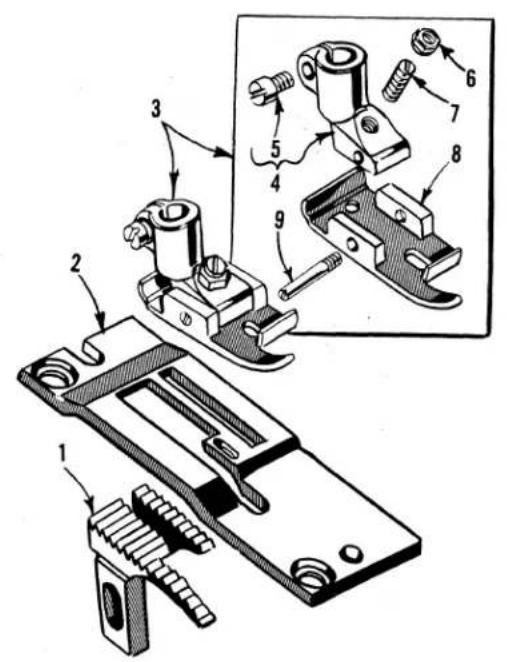
text_image
Technical diagram of a mechanical assembly with numbered parts, showing exploded and assembled views of components.
text_image
Technical diagram of a mechanical assembly with numbered parts for identification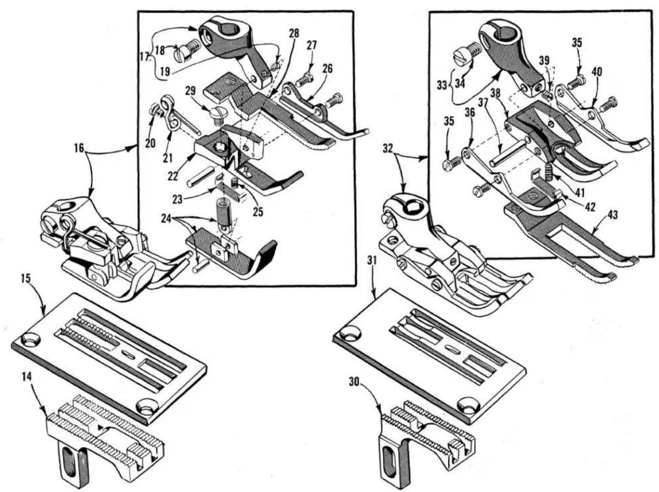
text_image
Technical diagram of a mechanical assembly with numbered parts, showing exploded and assembled views of components.FEED DOGS, THROAT PLATES, PRESSER FEET
| Ref.No. | PartNo. | Description | Amt.Req. | |
| 1 | 6405 M | Feed Dog, 12 teeth per inch, for Styles 56200 L and 56300 M - - - - - - - - - - - - - - - - - - - - - - - - - - - - - - - - - - - - - - - - - - - - - - - - - - - - - - - - - - - - - - - - - - - - - - - - - - - - - - - - - - - - - - - - - - - - - - - - - - - - | 1 | |
| 2 | 51224 B | Throat Plate, for Styles 56200 L and 56300 M - - - - - - - - - - - - - - - - - - - - - - - - - - - - - - - - - - - - - - - - - - - - - - - - - - - - - - - - - - - - - - - - - - - - - - - - - - - - - - - - - | ||
| 3 | 6420 W | Presser Foot, for Styles 56200 L and 56300 M - - - - - - - - - - - - - - - - - - - - - - - - - - - - - - - - - - - - - - - - - - - - - - - - - - - - - - - - - - - - - - - - - - - - - - - - - - - - - - - - - | 1 | |
| 4 | 6430 | Presser Foot Shank - - - - - - - - - - - - - - - - - - - - - - - - - - - - - - - - - - - - - - - - - - - - - - - - - - - - - - - - - - - - - - - - - - - - - - - - - - - - - - - - - - - - - - - - - - - - - - - - - - - | ||
| 5 | 91 | Clamp Screw - - - - - - - - - - - - - - - - - - - - - - - - - - - - - - - - - - - - - - - - - - - - - - - - - - - - - - - - - - - - - - - - - - - - - - - - - - - - - - - - - - - - - - - - - - - - - - - - - - - | ||
| 6 | 51430 F | Adjusting Nut - - - - - - - - - - - - - - - - - - - - - - - - - - - - - - - - - - - - - - - - - - - - - - - - - - - - - - - - - - - - - - - - - - - - - - - - - - - - - - - - - - - - - - - - - - - - - - - - - - - | ||
| 7 | 22840 A | Adjusting Screw - - - - - - - - - - - - - - - - - - - - - - - - - - - - - - - - - - - - - - - - - - - - - - - - - - - - - - - - - - - - - - - - - - - - - - - - - - - - - - - - - - - - - - - - - - - - - - - - - - | ||
| 8 | 6430 A | Presser Foot Bottom - - - - - - - - - - - - - - - - - - - - - - - - - - - - - - - - - - - - - - - - - - - - - - - - - - - - - - - - - - - - - - - - - - - - - - - - - - - - - - - - - - - - - - - | ||
| 9 | 22799 E | Hinge Screw - - - - - - - - - - - - - - - - - - - - - - - - - - - - - - - - - - - - - - - - - - - - - - - - - - - - - - - - - - - - - - - - - - - - - - - | ||
| 10 | 51205 A | Feed Dog, 16 teeth per inch, for Style 56200 K - - - - - - - - - - - - - - - - - - - - - - - - - - - - - - - - - - - - - - - - - - - - - - - - - - - - - - - - | ||
| 11 | 51224 A | Throat Plate, for Style 56200 K | - - - - - - - - - - - - - - - - - - - - - - - - - - - - - - - - - - - - - - - - - - - - - - - - - - - - - - - - - | |
| 12 | 51220 A | Presser Foot, for Style 56200 K | - - - - - - - - - - - - - - - - - - - - - - - - - - - - - - - - - - - - - - - - - - | |
| 13 | 91 | Clamp Screw | - - - - - - - - - - - - - - - - - - - - - - - - - - - - - - - - - - - - - - - | |
| 14 | 51305 W | Feed Dog, 22 teeth per inch, for Style 56300 AH | - - - - - - - - - - - - - - - - - - - - - - - - - - | |
| 15 | 51324 W | Throat Plate, for Style 56300 AH | - - - - - - - - - - - - - - - - - - - - - - - - | |
| 16 | 51320 W | Presser Foot, for Style 56300 AH | - - - - - - - - - - - - - - - - - - | |
| 17 | 51330 Z | Presser Foot Shank | - - - - - - - - - - - - | |
| 18 | 91 | Screw | - - - - - - - - - | |
| 19 | 1096 | Screw | - - - - - - - | |
| 20 | 604 | Screw | - - - - - - | |
| 21 | 19146 A | Spring | - - - - - - | |
| 22 | 56330 | Presser Foot Bottom, marked "AG" | - - - - - - | |
| 23 | 56330 F | Yielding Section | - - - - - | |
| 24 | 51330 AB | Presser Foot Yielding Section | - - - - - | |
| 25 | 56330 G | Spring | - - - - | |
| 26 | 51330 AE | Feeding Section Guide | - - - - | |
| 27 | 22738 | Screw | - - - - | |
| 28 | 51330 BB | Presser Foot Feeding Section, 22 teeth per inch | - 2 | |
| 29 | 22561 | Screw | - | |
| 30 | 51326 A | Feed Dog, 22 teeth per inch, for Style 56300 N | - | |
| 31 | 51324 F | Throat Plate, for Styles 56300 N, U- | - | |
| 32 | 51327 A | Presser Foot, for Style 56300 N | - | |
| 33 | 51330 M | Presser Foot Shank | - | |
| 34 | 91 | Screw | - | |
| 35 | 22738 | Screw | - | |
| 36 | 51330 P | Feed Section Guide, left | - | |
| 37 | 1594 A | Hinge Pin | - | |
| 38 | 56330 E | Presser Foot Bottom | - | |
| 39 | 1096 | Screw | - | |
| 40 | 51330 R | Feed Section Guide, right | - | |
| 41 | 61430 BT | Spring | - | |
| 42 | 56330 F | Yielding Section | - | |
| 43 | 51330 AX | Presser Foot Feeding Section, 22 teeth per inch | - | |

text_image
Technical diagram of mechanical assembly with numbered parts and exploded views, likely for assembly or manufacturing purposes.FEED DOGS, THROAT PLATES, PRESSER FEET
| Ref.No. | PartNo. | Description | Amt.Req. |
| 1 | 56205 | Feed Dog, 16 teeth per inch, for Style 56200 S - - - - - - - - - - - - - - - - - - - - - - - - - - - - - - - - - - - - - - - - - - - - - - - - - - - - - - - - - - - - - - - - - - - - - - - - - - - - - - - - - - - - - - - - - - - - - - - - - - - - | - - - - - - - - - - - - - - - - - - - - - - - - - - - - - - - - - - - - - - - - - - - - - - - - - - - - - - - - - - - - - - - - - - - - - - - - - - - - - - - - - - - - - - - - - - - - - - - - - - - - |
| 2 | 56224 | Throat Plate, for Style 56200 S- - - - - - - - - - - - - - - - - - - - - - - - - - - - - - - - - - - - - - - - - - - - - - - - - - - - - - - - - - - - - - - - - - - - - - - - - - - - - - - - - - - - - - - - - - - - - - - - - - - | 1 |
| 3 | 51320 N | Presser Foot, bottom marked "51330 AL" for Style 56200 S - - - - - - - - - - - - - - - - - - - - - - - - - - - - - - - - - - - - - - - - - - - - - - - - - - - - - - - - - - - - - - - - - - - - - - - - - - - - - - - - - - - - - - - - - - | - - - - - - - - |
| 4 | 187 B | Screw, for chain cutting knife - - - - - - - - - - - - - - - - - - - - - - - - - - - - - - - - - - - - - - - - - - - - - - - - - - - - - - - - - - - - - - - - - - - - - - - - - - - - - - - - - - - - - - - - - - - - - - - - - - - | |
| 5 | 1741 B | Chain Cutting Knife - - - - - - - - - - - - - - - - - - - - - - - - - - - - - - - - - - - - - - - - - - - - - - - - - - - - - - - - - - - - - - - - - - - - - - - - - - - - - - - - - - - - - - - - - - - - - - - - - - - | |
| 6 | 51330 AK | Shank - - - - - - - - - - - - - - - - - - - - - - - - - - - - - - - - - - - - - - - - - - - - - - - - - - - - - - - - - - - - - - - - - - - - - - - - - - - - - - - - - - - - - - - - - - - - - - - - - - - 1 | |
| 7 | 91 | Clamp Screw - - - - - - - - - - - - - - - - - - - - - - - - - - - - - - - - - - - - - - - - - - - - - - - - - - - - - - - - - - - - - - - - - - - - - - - - - - - - - - - - - - - - - - - - | - 1 |
| 8 | 51330 AL | Presser Foot Bottom | - - - - - - - - - - - - - - - - - - - - - - - - - - - - - - - - - - - - - - - - - - - - - - - - - - - - - - - - - - - - - - - - - - - - - - - - |
| 9 | 51330 W | Spring - - - - - - - - - - - - - - - - - - - - - - - - - - - - - - - - - - - - - - - - - - - - - - - - - - - - - - - - - - - - - - - - - - - - | - 1 |
| 10 | 51330 AM | Yielding Section - - - - - - - - - - - - - - - - - - - - - - - - - - - - - - - - - - - - - - - - - - - - - - - - - - - - - - - - - | - 1 |
| 11 | 51305 W | Feed Dog, 22 teeth per inch, for Styles 56300 F, R, AH | - - - - - - - - |
| 12 | 51324 W | Throat Plate, for Styles 56300 F, R, AH | - - - - - - - - |
| 13 | 56320 F | Presser Foot, for Style 56300 F- | - - - - - - - |
| 14 | 56330 AB | Presser Foot Bottom, marked "BS" | - - - - - - |
| 15 | 22799 B | Hinge Screw | - 1 |
| 16 | 73 A | Screw, for tilting spring | - 1 |
| 17 | 56330 AX | Tilting Spring | - 1 |
| 18 | 56330 AJ | Hinge Pin | - 1 |
| 19 | 56330 AG | Connecting Screw | - 1 |
| 20 | 604 | Screw, for chain cutting knife | - 1 |
| 21 | 52930 AC | Chain Cutting Knife, marked "D" | - 1 |
| 22 | 56330 AF | Hinge Screw | - 1 |
| 23 | 51430 F | Nut- | - 1 |
| 24 | 56330 AU | Washer | - 1 |
| 25 | 41071 G | Locking Nut | - 1 |
| 26 | 56330 AD | Compression Spring | - 1 |
| 27 | 56330 AH | Pressure Regulating Nut | - 1 |
| 28 | 56330 AK | Yoke | - 1 |
| 29 | 22785 | Screw | - 1 |
| 30 | 22560 B | Screw | - 1 |
| 31 | 88 | Screw | - 1 |
| 32 | 56330 AE | Presser Foot Link, marked "A" | - 1 |
| 33 | 56330 AP | Bushing | - 1 |
| 34 | 51305 U | Feed Dog, 12 teeth per inch, for Style 56300 W | - 1 |
| 35 | 9224 E | Throat Plate, for Styles 56300 G and 56300 W | - 1 |
| 36 | 51320 J | Presser Foot, for Style 56300 W | - 1 |
| 37 | 1741 A | Pin, for chain cutting knife | - 1 |
| 38 | 187 A | Screw, for chain cutting knife | - 1 |
| 39 | 1741 B | Chain Cutting Knife | - 1 |
| 40 | 22799 B | Hinge Screw | - 1 |
| 41 | 51330 X | Presser Foot Bottom | - 1 |
| 42 | 51330 Y | Presser Foot Shank | - 1 |
| 43 | 91 | Clamp Screw | - 1 |
| 44 | 51305 B | Feed Dog, 12 teeth per inch, for Style 56300 H | - 1 |
| 45 | 51324 B | Throat Plate, for Style 56300 H | - 1 |
| 46 | 51320 B | Presser Foot, for Style 56300 H | - 1 |
| 47 | 86 X | Hinge Screw | - 1 |
| 48 | 88 | Set Screw | - 2 |
| 49 | 65 XD | Presser Foot Shank | - 1 |
| 50 | 51330 B | Presser Foot Bottom | - 1 |

text_image
Technical diagram of a mechanical assembly with numbered parts, likely for repair or assembly instructions.
text_image
Technical diagram of mechanical assembly with numbered parts, likely a valve or clamp mechanism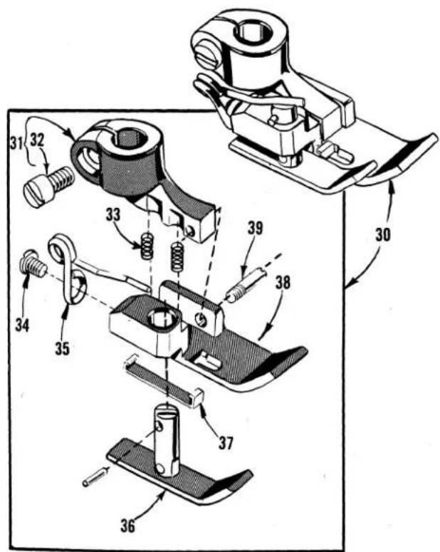
text_image
Technical diagram of a mechanical assembly with numbered parts, likely for assembly or maintenance instructions.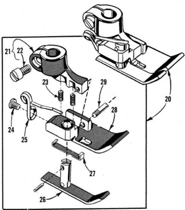
text_image
Technical diagram of mechanical assembly with numbered parts and directional arrows indicating motion or assembly steps.PRESSER FEET
| Ref.No. | PartNo. | Description | Amt.Req. | |
| * 1 | 56320 G | Presser Foot, bottom marked "BM" | - - - - - - - - - - - - - - - - - - - - - - - - - - - - - - - - - - - - - - - - - - - - - - - - - - - - - - - - - - - - - - - - - - - - - - - - - - - - - - - - - - - - - - - - - - - - - - - - - - - - - | |
| 2 | 56330 P | Presser Foot Shank | - - - - - - - - - - - - - - - - - - - - - - - - - - - - - - - - - - - - - - - - - - - - - - - - - - - - - - - - - - - - - - - - - - - - - - - - - - - - - - - - - - - - - - - - - - - - - - - - - - | |
| Clamp Screw | - - - - - - - - - - - - - - - - - - - - - - - - - - - - - - - - - - - - - - - - - - - - - - - - - - - - - - - - - - - - - - - - - - - - - - - - - - - - - - - - - - - - - - - - - - - - - - - - - - . | |||
| 4 | 187 A | Screw | - - - - - - - - - - - - - - - - - - - - - - - - - - - - - - - - - - - - - - - - - - - - - - - - - - - - - - - - - - - - - - - - - - - - - - - - - - - - - - - - - - - - - - - - - - - - - - - - - - | - 1 |
| 5 | 1741 B | Chain Cutting Knife | - - - - - - - - - - - - - - - - - - - - - - - - - - - - - - - - - - - - - - - - - - - - - - - - - - - - - - - - - - - - - - - - - - - - - - - - - - - - - - - - - - - - - - - - - - - - - - - - - - 1 | |
| 6 | 56330 T | Spring | - - - - - - - - - - - - - - - - - - - - - - - - - - - - - - - - - - - - - - - - - - - - - - - - - - - - - - - - - - - - - - - - - - - - - - - - - - - - - - - - - - - - - - - - - - - - - - - - - - | |
| 7 | 22799 B | Hinge Screw | - - - - - - - - - - - - - - - - - - - - - - - - - - - - - - - - - - - - - - - - - - - - - - - - - - - - - - - - - - - - - - - - - - - - - - - - - - - - - - - - - - - - - - - - - - - - - - - - - | |
| Yielding Section | - - - - - - - - - - - - - - - - - - - - - - - - - - - - - - - - - - - - - - - - - - - - - - - - - - - - - - - - - - - - - - - - - - - - - - - - - - - - - - - - | |||
| 9 | 56330 R | Presser Foot Bottom, marked "BM" | - - - - - - - - - - - - - - - - - - - - - - - - - - - - - - - - - - - - - - - - - - - - - - - - - - - - - - - - - - - - - - - - - - - - - - - - - - - - - - - - - - - - - | |
| *10 | 56320 B | Presser Foot | - - - - - - - - - - - - - - - - - - - - - - - - - - - - - - - - - - - - - - - - - - - - - - - - - - - - - - - - - - - - - - - - - - - - - - - - - - - - - - - - - - - | |
| 11 | 56330 U | Presser Foot Shank | - - - - - - - - - - - - - - - - - - - - - - - - - - - - - - - - - - - - - - - - - - - - - - - - - - - - - - - - - - - - - - - - - - - | |
| 12 | 91 | Clamp Screw | - - - - - - - - - - - - - - - - - - - - - - - - - - - - - - - - - - - - - - - - - - - - - - - - - - | |
| 13 | 61430 BT | Spring | - - - - - - - - - - - - - - - - - - - - - - - - - - - - - - - - - - - - - - - - - - - - - - - - - | |
| 14 | 604 | Screw | - - - - - - - - - - - - - - - - - - - - - - - - - - - - - - - - - - - - | |
| 15 | 19146 A | Spring | - - - - - - - - - - - - - - - - - - - - - - - - - - | |
| 16 | 56330 Y | Yelding Section | - - - - - - - - - - - - - - - - - - - - - - - - | |
| 17 | 56330 AA | Yielding Section | - - - - - - - - - - - | |
| 18 | 56330 W | Presser Foot Bottom | - - - - - - - - - | |
| 19 | 22799 G | Hinge Screw | - - - - - | |
| *20 | 56320 C | Presser Foot | - - - - | |
| 21 | 56330 U | Presser Foot Shank | - | |
| 22 | 91 | Clamp Screw | - | |
| 23 | 61430 BT | Spring | - | |
| 24 | 604 | Screw | - | |
| 25 | 19146 A | Spring | - | |
| 26 | 56330 Y | Yielding Section | - | |
| 27 | 56330 AA | Yielding Section | - | |
| 28 | 56330 X | Presser Foot Bottom | - | |
| 29 | 22799 G | Hinge Screw | - | |
| *30 | 56320 D | Presser Foot | - | |
| 31 | 56330 U | Presser Foot Shank | - | |
| 32 | 91 | Clamp Screw | - | |
| 33 | 61430 BT | Spring | - | |
| 34 | 604 | Screw | - | |
| 35 | 19146 A | Spring | - | |
| 36 | 56330 V | Yielding Section | - | |
| 37 | 56330 AA | Yielding Section | - | |
| 38 | 56330 W | Presser Foot Bottom | - | |
| 39 | 22799 G | Hinge Screw | - |
* Available as an extra send and charge item.
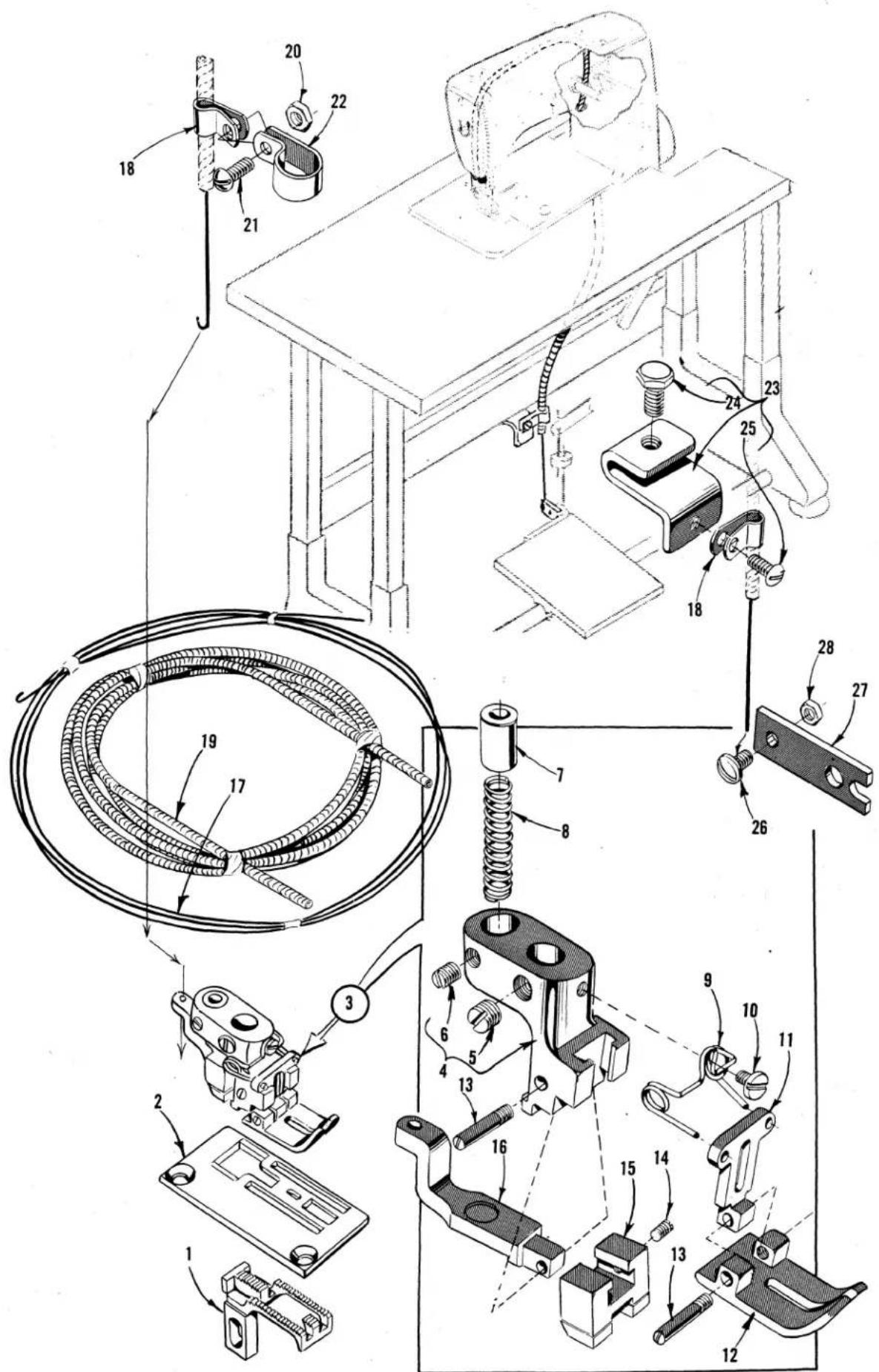
text_image
Technical diagram of a mechanical assembly with numbered components and labeled partsAUTOMATIC CHAIN CUTTER AND PRESSURE RELEASE ATTACHMENT FOR STYLE 56300 E
| Ref.No. | PartNo. | Description | Amt.Req. |
| 1 | 51305 V | Feed Dog, marked "BN", 22 teeth per inch | - - - - - - 1 |
| 2 | 51324 V | Throat Plate | - - - - - - 1 |
| 3 | 56320 A | Presser Foot, bottom marked "AU" | - - - - - - 1 |
| 4 | 56330 H | Presser Foot Shank | - - - - - - 1 |
| 5 | 88 | Screw, for presser foot shank | - - - - - - 1 |
| 6 | HA73 B | Screw, for spring adjusting pin | - - - - - - 1 |
| 7 | 56330 N | Spring Adjusting Pin | - - - - - - 1 |
| 8 | 56330 J | Chain Cutter Spring | - - - - - - 1 |
| 9 | 61430 AJ | Spring, for presser foot bottom | - - - - - - 1 |
| 10 | 73 A | Screw, for spring | - - - - - - 1 |
| 11 | 56330 M | Yielding Section, marked "AS" | - - - - - - 1 |
| 12 | 56330 L | Presser Foot Bottom, marked "AU" | - - - - - - 1 |
| 13 | 22799 R | Hinge Screw | - - - - - - 2 |
| 14 | HA73 B | Screw, for chain cutter | - - - - - - 1 |
| 15 | 61430 AN | Chain Cutter, marked "G" | - - - - - - 1 |
| 16 | 56330 K | Adjusting Slide | - - - - - - 1 |
| 17 | 51330 BC | Chain Cutter Release Cable | - - - - - - 1 |
| 18 | 660-406 | Stationary Cable Clamp | - - - - - - 2 |
| 19 | 51330 BD | Chain Cutter Release Cable Casing | - - - - - - 1 |
| 20 | NU-12 | Nut | - - - - - - 1 |
| 21 | SC-180 | Screw | - - - - - - 1 |
| 22 | 660-437 | Presser Bar Bushing Clamp | - - - - - - 1 |
| 23 | 51330 BF | Stationary Cable Clamp | - - - - - - 1 |
| 24 | SC-2 | Screw | - - - - - - 1 |
| 25 | SC-178 | Screw | - - - - - - 1 |
| 26 | 22848 A | Screw | - - - - - - 1 |
| 27 | 51330 BE | Pedal Connection | - - - - - - 1 |
| 28 | 12934 A | Nut, for cable adjusting screw | - - - - - - 1 |
NOTE: Automatic Chain Cutting Release Attachment Kit No. 29480 GJ, consists of Ref. Nos. 17 thru 28 inclusive.
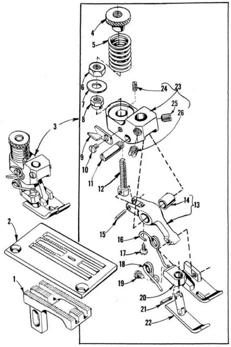
text_image
Technical diagram of mechanical assembly with numbered parts, likely a valve or clamp mechanism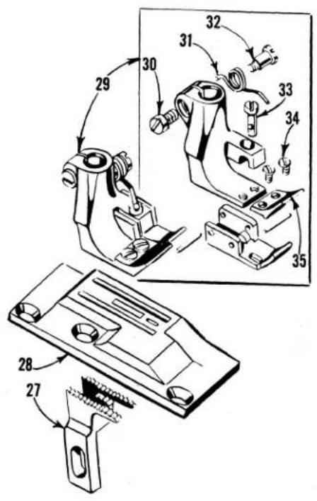
text_image
Technical diagram of mechanical assembly with numbered parts and exploded view, likely from an engineering manual.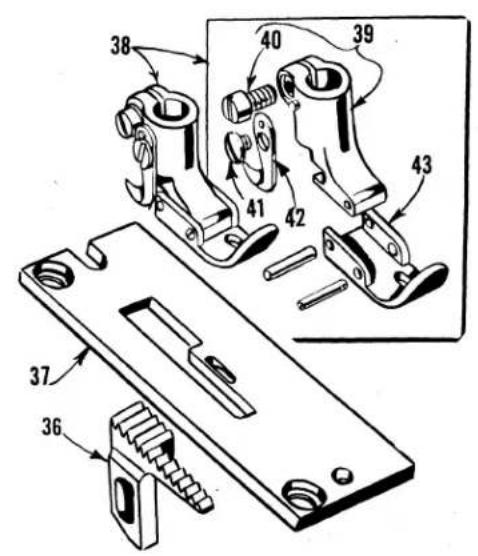
text_image
Technical diagram of a mechanical assembly with numbered parts, likely for repair or assembly instructions.
text_image
Technical diagram of a mechanical assembly with numbered parts, likely for assembly or maintenance instructions.FEED DOGS, THROAT PLATES, PRESSER FEET
| Ref.No. | PartNo. | Description | Amt.Req. | |||
| 1 | 51305 W | Feed Dog, 22 teeth per inch, for Styles 56300 F, R, AH | - - - 1 | |||
| 2 | 51324 W | Throat Plate, for Styles 56300 F, R, AH | - - - - - - - - - - - - - - - - - - - - - - - - - - - - - - - - - - - - - - - - - - - - - - - - - - - - - - - - - - - - - - - - - - - - - - - - - - - - - - - - - - - - - - - - - - - - - - - - - - - - - | |||
| 3 | 56320 H | Presser Foot, for Style 56300 R | - - - - - - - - - - - - - - - - - - - - - - - - - - - - - - - - - - - - - - - - - - - - - - - - - - - - - - - - - - - - - - - - - - - - - - - - - - - - - - - - - - - - - - - - - - - - - - - - - - | |||
| 4 | 56330 AH | Pressure Regulating Nut | - - - - - - - - - - - - - - - - - - - - - - - - - - - - - - - - - - - - - - - - - - - - - - - - - - - - - - - - - - - - - - - - - - - - - - - - - - - - - - - - - - - - - - - - - - - - - - - - - - | |||
| 5 | 56330 AD | Compression Spring | - - - - - - - - - - - - - - - - - - - - - - - - - - - - - - - - - - - - - - - - - - - - - - - - - - - - - - - - - - - - - - - - - - - - - - - - - - - - - - - - - - - - - - - - - - - - - - - - - - | - - - - - - - - - - - - - - - - - - - - - - - - - - - - - - - - - - - - - - - - - - - - - - - - - - - - - - - - - - - - - - - - - - - - - - - - - - - - - - - - - - - - - - - - - - - - - - - - - - – | ||
| 6 | 41071 G | Locking Nut | - - - - - - - - - - - - - - - - - - - - - - - - - - - - - - - - - - - - - - - - - - - - - - - - - - - - - - - - - - - - - - - - - - - - - - - - - - - - - - - - - - - - - - - - - - - - - - - - - – | - - - - - - - - - - - - - - - - - - - - - - - - - - - - - - - - - - - - - - - - - - - - - - - - - - - - - - - - - - - - - - - - - - - - - - - - - - - - - - - - – | ||
| 7 | 56330 AU | Washer | - - - - - - - - - - - - - - - - - - - - - - - - - - - - - - - - - - - - - - - - - - - - - - - - - - - - - - - - - - - - - - - - - - - - - - - - - - - - - - - - - - - – | - - - - - - - - – – – – – – – – – – – – – – – – – – – – – – – – – – – – – – – – – – – – – – – – – – – – – – – – – – – – – – – – – – – – – – – – – – – – – – – – – – – – – – – – – – – – – – – – – – – – – – – – – – – – — – – – – – – – – – – – – – – – – – – – – – – – – – – – – – – – – – – – – – – – – – – – – – – – – – – – – – – – – – – – – – – – – – – – – – – – – – – – – – – – – – – – – – – – – – – – – – – – – – – – × – – – – – – – – – – – – – – – – – – – – – – – – – – – – – – – – – – – – – – – – – – – – – – – – – – – – – – – – – – – – – – – – – – – – – – – – – – – – – – – – – – – – – – – – – – – – – – – – – – – _ – – – – – – – – – – – – – – – – – – – – – – – – – – – – – – – – – – – – – – – – – – – – – – – – – – – – – – – – – – – – – – – – – – – – – – – – – – – – – – – – – – – – – – – – – – – – – – – – – – –– – – – – – – – – – – – – – – – – – – – – – – – – – – – – – – – – – – – – – – – – – – – – – – – – – – – – – – – – – – – – – – – – – – – – – – – – – – – – – – – – – – – – – – – – – – – – – – – – – – – ~ – – – – – – – – – – – – – – – – – – – – – – – – – – – – – – – – – – – – – – – – – – – – – – – – – – – – – – – – – – – – – – – – – – – – – – – – – – – – – – – – – – – – – – – – – – – – – – – – – – – ’’ | – – – – – – – – – – – – – – – – – – – – – – – – – – – – – – – – – – – – – – – – – – – – – – – – – – – – – – – – – – – – – – – – – – – – – – – – – – – – – – – – – – – – – – – – – – – – – – – – – – – — | – – – – – – – – – – – – – – – – – – – – – – – – – – – – – – – – – – – – – – – – – – – – – – – – – – – – – – – – – – – – – – – – – – – – – – – – – – – – – – – – – – – – – – – – – – – – – – – – – – — |
| 10 | 604 | Screw, for chain cutting knife | - - - - - - - - - - - - - - - - - - - - - - - - - - - - - - - - - - - - - - - - - - - - - - - - - - - - - - - - - - - - - - - - - - - — | - — — — — — — — — — — — — — — — — — — — — — — — — — — — — — — — — — — — — — — — — — — — — — — — — — — — — — — — — — — — — — — — — — — — — — — — — — — — — — — — — — — — — — — — — — — — — — — — — — — — — | ||
| 11 | 56330 AF | Hinge Screw | - — — — — — — — — — — — — — — — — — — — — — — — — — — — — — — — — — — — — — — — — — — — — — — — — — — — — — — — — — — — — — — — — — — — — — — — — — — — — — — — — — — — — — — — — — — — — — — — — — | - — — — — — — — — — — — — — — — — — — — — — — — — — — — — — — — — — — — — — — — — — — — — — — — — — — — — — — — — — — — — — — — — — — — — — — — — — — — — — — — — — — — — — — — — — — — — — — — — | ||
| 2 | 56330 AG | Connecting Screw | - — — — — — — — — — — — — — — — — — — — — — — — — — — — — — — — — — — — — — — — — — — — — — — — — — — — — — — — — — — — — — — — — — — — — — — — — — — — — — — — — — — — — — — — — — — — — — — — — | - —— —— —— —— —— —— —— —— —— —— —— —— —— —— —— —— —— —— —— —— —— —— —— —— —— —— —— —— —— —— —— —— —— —— —— —— —— —— —— —— —— —— —— —— —— —— —— —— —— —— — | ||
| 13 | 56330 AN | Presser Foot Link, marked "B" | - — — — — — — — — — — — — — — — — — — — — — — — — — — — — — — — — — — — — — — — — — — — — — — — — — — — — — — — — — — — — — — — — — — — — — — — — — — — — — — — — — — — — — — — — — — — — — — — — — | |||
| 14 | 56330 AP | Bushing | - — — — — — — — — — — — — — — — — — — — — — — — — — — — — — — — — — — — — — — — — — — — — — — — — — — — — — — — — — — — — — — — — — — — — — — — — — — — — — — — — — — — — — — — — — — — — — — — — —— | - —— —— —— —— —— —— —— —— —— —— —— —— —— —— —— —— —— —— —— —— —— —— —— —— —— —— —— —— —— —— —— —— —— —— —— —— —— —— —— —— —— —— —— —— —— —— —— —— — |

text_image
Technical diagram of a mechanical clamp assembly with numbered parts and exploded view
text_image
Technical diagram of a mechanical clamp assembly with numbered parts for identification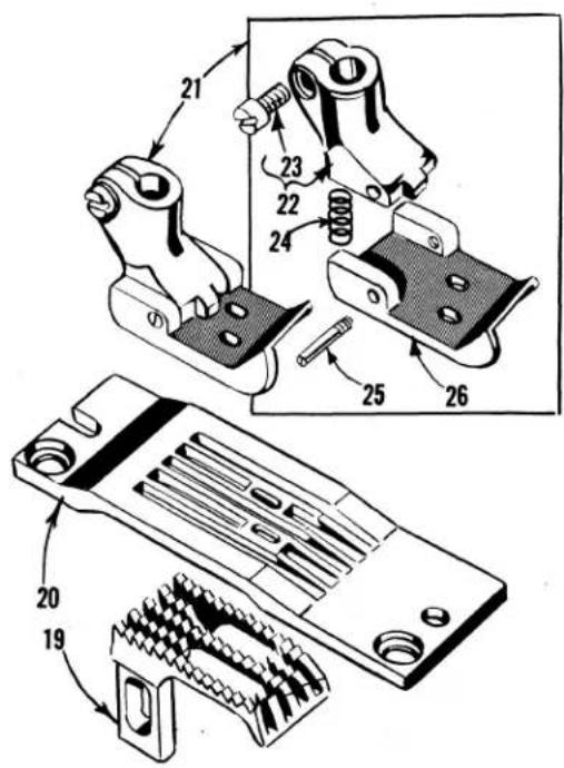
text_image
Technical diagram of mechanical components with numbered parts, showing assembly and disassembly views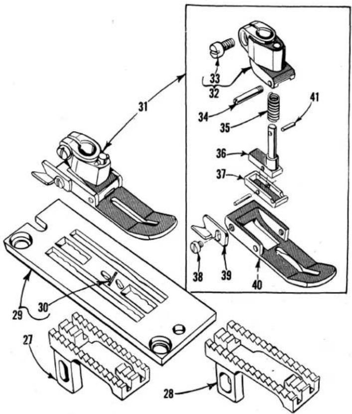
text_image
Technical diagram of mechanical assembly with numbered parts and exploded view, likely for assembly or manufacturing documentation.FEED DOGS, THROAT PLATES, PRESSER FEET
| Ref.No. | PartNo. | Description | Amt.Req. |
| 1 | 51405 A-8 | Feed Dog, 16 teeth per inch, for Nos. 6 and 8 gauges, Style 56400 P | -1 |
| 51405 A-10 | Feed Dog, 16 teeth per inch, for Nos. 10 and 12 gauges, Style 56400 P | -1 | |
| 2 | 51424 A-6 | Throat Plate, for No. 6 gauge, Style 56400 P | -1 |
| 51424 A-8 | Throat Plate, for No. 8 gauge, Style 56400 P | -1 | |
| 51424 A-10 | Throat Plate, for No. 10 gauge, Style 56400 P | -1 | |
| 51424 A-12 | Throat Plate, for No. 12 gauge, Style 56400 P | -1 | |
| 3 | 51420-6 | Presser Foot, for No. 6 gauge, Style 56400 P | -1 |
| 51420-10 | Presser Foot, for No. 8 gauge, Style 56400 P | -1 | |
| 51420-12 | Presser Foot, for No. 12 gauge, Style 56400 P | -1 | |
| 4 | 51430 D | Presser Foot Shank | -1 |
| 5 | 91 | Screw | -1 |
| 6 | 22799 B | Hinge Screw | -1 |
| 7 | 51430 A-16 | Presser Foot Bottom, for No. 51420-6 presser foot | -1 |
| 51430 A-8 | Presser Foot Bottom, for No. 51420-8 presser foot | -1 | |
| 51430 A-10 | Presser Foot Bottom, for No. 51420-10 presser foot | -1 | |
| 51430 A-12 | Presser Foot Bottom, for No. 51420-12 presser foot | -1 | |
| 8 | 22840 A | Adjusting Screw | -1 |
| 9 | 51430 F | Adjusting Nut | -1 |
| 10 | 51405-16 | Feed Dog, 16 teeth per inch, for Nos. 16 and 18 gauges, Style 56400 P | -1 |
| 11 | 51424-16 | Throat Plate, for No. 16 gauge, Style 56400 P | -1 |
| 51424-18 | Throat Plate, for No. 18 gauge, Style 56400 P | -1 | |
| 12 | 51420-16 | Presser Foot, for No. 16 gauge, Style 56400 P | -1 |
| 51420-18 | Presser Foot, for No. 18 gauge, Style 56400 P | -1 | |
| 13 | 51430 D | Presser Foot Shank | -1 |
| 14 | 91 | Screw | -1 |
| 15 | 22799 B | Hinge Screw | -1 |
| 16 | 51430 A-16 | Presser Foot Bottom, for No. 51420-16 presser foot | -1 |
| 51430 A-18 | Presser Foot Bottom, for No. 51420-18 presser foot | -1 | |
| 17 | 22840 A | Adjusting Screw | -1 |
| 18 | 51430 F | Adjusting Nut- | -1 |
| 19 | 51505-18 | Feed Dog, 12 teeth per inch, for Nos. 16 and 18 gauges, Style 56500 J | -1 |
| 20 | 51524-16 | Throat Plate, for No. 16 gauge, Style 56500 J | -1 |
| 51524-18 | Throat Plate, for No. 18 gauge, Style 56500 J | -1 | |
| 21 | 51520-16 | Presser Foot, for No. 16 gauge, Style 56500 J- | -1 |
| 51520-18 | Presser Foot, for No. 18 gauge, Style 56500 J- | -1 | |
| 22 | 35830 | Presser Foot Shank | -1 |
| 23 | 91 | Screw | -1 |
| 24 | 51930 | Spring | -1 |
| 25 | 22799 C | Hinge Pin | -1 |
| 26 | 51530-16 | Presser Foot Bottom, for No. 51520-16 presser foot | -1 |
| 51530-18 | Presser Foot Bottom, for No. 51520-18 presser foot | -1 | |
| 27 | 56505 | Feed Dog, 10 teeth per inch, for 7 and 10 S.P.I.,Styles 56500 B, C | -1 |
| 28 | 56505 B | Feed Dog, 10 teeth per inch, for 5 S.P.I., Style 56500 A | -1 |
| 29 | 56524 A-1 | Throat Plate, for 5 S.P.I., Style 56500 A- | -1 |
| - | 56524 B-1 | Throat Plate, for 7 S.P.I., Style 56500 B- | -1 |
| - | 56528 C-1 | Throat Plate, for 10 S.P.I., Style 56500 C | -1 |
| 30 | 56528 | Insert | -1 |
| 31 | 56520 | Presser Foot, all stitches per inch, Styles 56500 A, B, C, U | -1 |
| 32 | 51530 D | Presser Foot Shank | -1 |
| 33 | 91 | Screw | -1 |
| 34 | 22799 E | Hinge Screw | -1 |
| 35 | 51530 G | Spring | -1 |
| 36 | 51530 F | Plunger- | -1 |
| 37 | 56530 A | Yielding Section | -1 |
| 38 | 91 A | Screw | -1 |
| 39 | 52930 AC | Chain Cutting Knife, Marked "D" | -1 |
| 40 | 56530 | Presser Foot Bottom | -1 |
| 41 | 1740 | Pin | -1 |
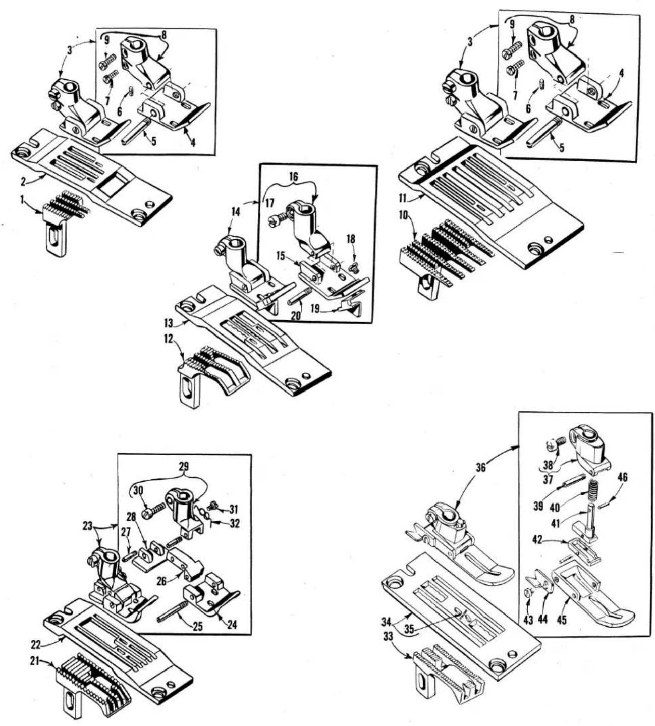
FEED DOGS, THROAT PLATES, PRESSER FEET
| Ref.No. | PartNo. | Description | Amt.Req. |
| 1 | 51405 B-32 | Feed Dog, 16 teeth per inch, for No. 32 gauge, Style 56400 S - - - - - - - - - - - - - - - - - - - - - - - - - - - - - - - - - - - - - - - - - - - - - - - - - - - - - - - - - - - - - - - - - - - - - - - - - - - - - - - - - - - - - - - - - - - - - - - - - - - - | 1 |
| - | 51405 B-48 | Feed Dog, 16 teeth per inch, for No. 48 gauge, Style 56400 S - - - - - - - - - - - - - - - - - - - - - - - - - - - - - - - - - - - - - - - - - - - - - - - - - - - - - - - - - - - - - - - - - - - - - - - - - - - - - - - - - - - - - - - - - | 1 |
| 2 | 51424 B-32 | Throat Plate, for No. 32 gauge, Style 56400 S- - - - - - - - - - - - - - - - - - - - - - - - - - - - - - - - - - - - - - - - - - - - - - - - - - - - - - - - - - - - - - - - - - - - - - - - - - - - - - - - - - - - - - - - - - - - - - - - - - - - | |
| - | 51424 B-48 | Throat Plate, for No. 48 gauge, Style 56400 S- - - - - - - - - - - - - - - - - - - - - - - - - - - - - - - - - - - - - - - - - - - - - - - - - - - - - - - - - - - - - - - - - - - - - - - - - - - - - - - - - - - - - - - - - | |
| 3 | 51420 C-32 | Presser Foot, for No. 32 gauge, Style 56400 S- - - - - - - - - - - - - - - - - - - - - - - - - - - - - - - - - - - - - - - - - - - - - - - - - - - - - - - - - - - - - - - - - - - - - - - - - - - - - - - - - - | |
| - | 51420 C-48 | Presser Foot, for No. 48 gauge, Styles 56400 R, S - - - - - - - - - - - - - - - - - - - - - - - - - - - - - - - - - - - - - - - - - - - - - - - - - - - - - - - - - - - - - - - - - - - - - - - - - - - - - - - - - - - - - | |
| 4 | 51430 C-32 | Presser Foot Bottom, for No. 51420 C-32 presser foot - - - - - - - - - - - - - - - - - - - - - - - - - - - - - - - - - - - - - - - - - - - - - - - - - - - - - - - - - - - - - - - - - - - - - | |
| - | 51430 C-48 | Presser Foot Bottom, for No. 51420 C-48 presser foot - - - - - - - - - - - - - - - - - - - - - - - - - - - - - - - - - - - - - - - - - - - - - - - - - - - - - - - - - - | |
| 5 | 22799 D | Hinge Screw - - - - - - - - - - - - - - - - - - - - - - - - - - - - - - - - - - - - - - - - - - - - - - - - - - - - - - - - - - - - - - - - | |
| 6 | 22752 B | Adjusting Screw - - - - - - - - - - - - - - - - - - - - - - - - - - - - - - - - - - - - - - - - - - - - - | |
| 7 | 77 | Clamp Screw, lower - - - - - - - - - - - - - - - - - - - - - - - - - - - - - - - - - - - - - - - | |
| 8 | 51430 | Presser Foot Shank - - - - - - - - - - - - - - - - - - - - - - - - - - - - - - - | |
| 9 | 91 | Clamp Screw, upper - - - - - - - - - - - - - - - - - - - | |
| 10 | 51405 C-48 | Feed Dog, 16 teeth per inch, for No. 48 gauge, Style 56400 R - - - - - - - - - - - | |
| 11 | 51424 C-48 | Throat Plate, for No. 48 gauge, Style 56400 R- - - - - - | |
| 12 | 51405 K-26 | Feed Dog, 16 teeth per inch, for Nos. 24 and 26 gauge, Style 56400 X - - - - - - - - - | |
| 13 | 51424 K-24 | Throat Plate, for No. 24 gauge, Style 56400 X- - - - - | |
| - | 51424 K-26 | Throat Plate, for No. 26 gauge, Style 56400 X- | |
| 14 | 51420 K-24 | Presser Foot, for No. 24 gauge, Style 56400 X- | |
| - | 51420 K-26 | Presser Foot, for No. 26 gauge, Style 56400 X- | |
| 15 | 51430 K-24 | Presser Foot Bottom, for No. 51420 K-24 presser foot - - - - - | |
| - | 51430 K-26 | Presser Foot Bottom, for No. 51420 K-26 presser foot- | |
| 16 | 51430 B | Presser Foot Shank - - - - - | |
| 17 | 91 | Clamp Screw | |
| 18 | 187 A | Screw, for guide | |
| 19 | 53530 E | Guide | |
| 20 | 22799 B | Hinge Screw | |
| 21 | 51505 BR-18 | Feed Dog, 12 teeth per inch, for No. 18 gauge, Style 56500 R - - - - | |
| 22 | 51524 BR-18 | Throat Plate, for No. 18 gauge, Style 56500 R- | |
| 23 | 51520 BR-18 | Presser Foot, for No. 18 gauge, Style 56500 R- | |
| 24 | 51530 BR-18 | Presser Foot Bottom, front section | |
| 25 | 22799 C | Hinge Screw | |
| 26 | 35730 AC | Hinged Section | |
| 27 | 22799 G | Hinge Screw | |
| 28 | 51530 J | Presser Foot Bottom, rear section | |
| 29 | 35730 AD | Presser Foot Shank | |
| 30 | 91 | Clamp Screw | |
| 31 | 73 A | Screw, for spring | |
| 32 | 35730 AE | Spring | |
| 33 | 56505 A | Feed Dog, 22 teeth per inch, for No. 1 gauge, Style 56500 U | |
| 34 | 56528 B-1 | Throat Plate, for No. 1 gauge, Style 56500 U | |
| 35 | 56528 | Insert | |
| 36 | 56520 | Presser Foot, for No. 1 gauge, Styles 56500 A, B, C, U | |
| 37 | 51530 D | Presser Foot Shank | |
| 38 | 91 | Clamp Screw | |
| 39 | 22799 E | Hinge Screw | |
| 40 | 51530 G | Spring | |
| 41 | 51530 F | Plunger | |
| 42 | 56530 A | Yielding Section | |
| 43 | 91 A | Screw, for chain cutting knife | |
| 44 | 52930 AC | Chain Cutting Knife, marked "D" | |
| 45 | 56530 | Presser Foot Bottom | |
| 46 | 1740 | Pin |

text_image
Technical diagram of mechanical assembly with numbered components and directional arrows indicating motion or assembly steps.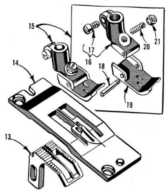
text_image
Technical diagram of a mechanical assembly with numbered parts, likely for assembly or repair instructions.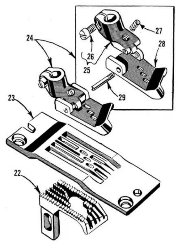
text_image
Technical diagram of a mechanical assembly with numbered parts, showing exploded and assembled views of components.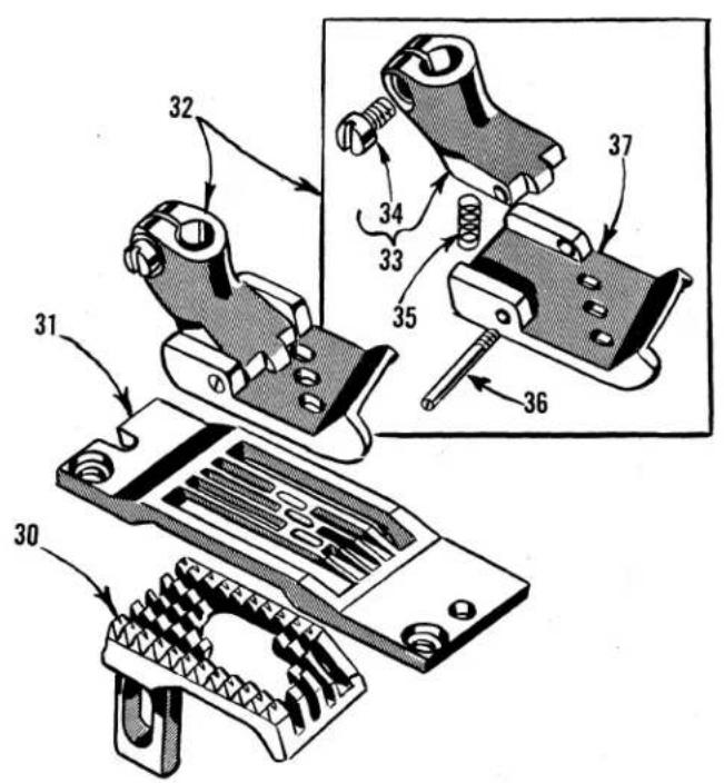
text_image
Technical diagram of mechanical clamping device components with numbered parts and exploded viewFEED DOGS, THROAT PLATES, PRESSER FEET
| Ref.No. | PartNo. |
| 1 | 51405 R-8 |
| 51405 R-12 | |
| 2 | 51424 R-8 |
| 51424 R-10 | |
| 51424 R-12 | |
| 51424 R-16 | |
| 3 | 51420 R-8 |
| 51420 R-10 | |
| 51420 R-12 | |
| 51420 R-16 | |
| 4 | 35730 AD |
| 5 | 91 |
| 6 | 35730 AB |
| 7 | 22799 G |
| 8 | 35730 AC |
| 9 | 22799 E |
| 10 | 51430 R-8 |
| 51430 R-10 | |
| 51430 R-12 | |
| 51430 R-16 | |
| 11 | 35730 AE |
| 12 | 73 A |
| 13 | 51405 G-8 |
| 51405 G-16 | |
| 14 | 51424 E-8 |
| 51424 E-10 | |
| 51424 E-12 | |
| 51424 E-16 | |
| 15 | 51420 E-8 |
| 51420 E-10 | |
| 51420 E-12 | |
| 51420 E-16 | |
| 16 | 51430 D |
| 17 | 91 |
| 18 | 22799 B |
| 19 | 51430 E-8 |
| 51430 E-10 | |
| 51430 E-12 | |
| 51430 E-16 | |
| 20 | 22840 A |
| 21 | 51430 F |
| 22 | 51905 A-7 |
| 23 | 51924 A-7 |
| 24 | 51920-7 |
| 25 | 51930 A |
| 26 | 91 |
| 27 | 12935 A |
| 28 | 51930 B-7 |
| 29 | 22799 B |
| 30 | 51905 B-9 |
| 31 | 51924 B-8 |
| 51924 B-9 | |
| 32 | 35820 P-8 |
| 35820 P-9 | |
| 33 | 35830 |
| 34 | 91 |
| 35 | 51930 |
| 36 | 22799 C |
| 37 | 35830 P-8 |
| 35830 P-9 |
| Description | Amt. Req. |
| Feed Dog, 16 teeth per inch, for Nos. 8 and 10 gauges, Style 56400 W | 1 |
| Feed Dog, 16 teeth per inch, for Nos. 12 and 16 gauges, Style 56400 W | 1 |
| Throat Plate, for No. 8 gauge, for Style 56400 W | 1 |
| Throat Plate, for No. 10 gauge, for Style 56400 W | 1 |
| Throat Plate, for No. 12 gauge, for Style 56400 W | 1 |
| Throat Plate, for No. 16 gauge, for Style 56400 W | 1 |
| Presser Foot, for No. 8 gauge, for Style 56400 W | 1 |
| Presser Foot, for No. 10 gauge, for Style 56400 W | 1 |
| Presser Foot, for No. 12 gauge, for Style 56400 W | 1 |
| Presser Foot, for No. 16 gauge, for Style 56400 W | 1 |
| Shank | 1 |
| Clamp Screw | 1 |
| Bottom, rear section | 1 |
| Hinge Screw, for bottom, rear section | 2 |
| Hinged Section | 1 |
| Hinge Screw, for bottom, front section | 1 |
| Bottom, front section, for No. 51420 R-8 presser foot | 1 |
| Bottom, front section, for No. 51420 R-10 presser foot | 1 |
| Bottom, front section, for No. 51420 R-12 presser foot | 1 |
| Bottom, front section, for No. 51420 R-16 presser foot | 1 |
| Spring | 1 |
| Screw | 1 |
| Feed Dog, 22 teeth per inch, for Nos. 8, 10 and 12 gauges, Style 56400 T | 1 |
| Feed dog, 22 teeth per inch for No. 16 gauge, Style 56400 T | 1 |
| Throat Plate, for No. 8 gauge, for Style 56400 T | 1 |
| Throat Plate, for No. 10 gauge, for Style 56400 T | 1 |
| Throat Plate, for No. 12 gauge, for Style 56400 T | 1 |
| Throat Plate, for No. 16 gauge, for Style 56400 T | 1 |
| Presser Foot, for No. 8 gauge, for Style 56400 T | 1 |
| Presser Foot, for No. 10 gauge, for Style 56400 T | 1 |
| Presser Foot, for No. 12 gauge, for Style 56400 T | 1 |
| Presser Foot, for No. 16 gauge, for Style 56400 T | 1 |
| Shank | 1 |
| Clamp Screw | 1 |
| Hinge Screw | 1 |
| Presser Foot Bottom, for No. 51420 E-8 presser foot | 1 |
| Presser Foot Bottom, for No. 51420 E-10 presser foot | 1 |
| Presser Foot Bottom, for No. 51420 E-12 presser foot | 1 |
| Presser Foot Bottom, for No. 51420 E-16 presser foot | 1 |
| Screw, for adjusting tilt of presser foot | 1 |
| Nut | 1 |
| Feed Dog, 16 teeth per inch, for No. 7 gauge, Style 56900 H | 1 |
| Throat Plate, for No. 7 gauge, for Style 56900 H | 1 |
| Presser Foot, for No. 7 gauge, for Style 56900 H | 1 |
| Presser Foot Shank | 1 |
| Clamp Screw | 1 |
| Adjusting Screw | 1 |
| Presser Foot Bottom | 1 |
| Hinge Screw | 1 |
| Feed Dog, 10 teeth per inch, for Nos. 8 and 9 gauges, Style 56900 H | 1 |
| Throat Plate, for No. 8 gauge, for Style 56900 H | 1 |
| Throat Plate, for No. 9 gauge, for Style 56900 H | 1 |
| Presser Foot, for No. 8 gauge, for Style 56900 H | 1 |
| Presser Foot, for No. 9 gauge, for Style 56900 H | 1 |
| Presser Foot Shank | 1 |
| Clamp Screw | 1 |
| Spring | 1 |
| Hinge Screw | 1 |
| Presser Foot Bottom, for No. 35820 P-8 presser foot | 1 |
| Presser Foot Bottom, for No. 35820 P-9 presser foot | 1 |
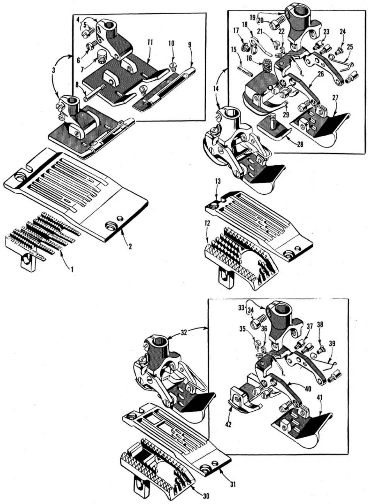
text_image
Technical diagram of mechanical components with numbered parts, showing exploded and assembled views of a device assembly.FEED DOGS, THROAT PLATES, PRESSER FEET
| Ref.No. | PartNo. | Description | Amt.Req. |
| 1 | 51705-64 | Feed Dog, 16 teeth per inch, for No. 64 gauge,Style 56700 J - - - - - - - - - - - - - - - - - - - - - - - - - - - - - - - - - - - - - - - - - - - - - - - - - - - - - - - - - - - - - - - - - - - - - - - - - - - - - - - - - - - - - - - - - - - - - - - - - - - - | 1 |
| 51705-56 | Feed Dog, 16 teeth per inch, for No. 56 gauge,Style 56700 J - - - - - - - - - - - - - - - - - - - - - - - - - - - - - - - - - - - - - - - - - - - - - - - - - - - - - - - - - - - - - - - - - - - - - - - - - - - - - - - - - - - - - - - - - | 1 | |
| 2 | 51724-64 | Throat Plate, for No. 64 gauge, Style 56700 J- - - - - - - - - - - - - - - - - - - - - - - - - - - - - - - - - - - - - - - - - - - - - - - - - - - - - - - - - - - - - - - - - - - - - - - - - - - - - - - - - - - - - - - - - - - - - - - - - - - - | |
| 51724-56 | Throat Plate, for No. 56 gauge, Style 56700 J- - - - - - - - - - - - - - - - - - - - - - - - - - - - - - - - - - - - - - - - - - - - - - - - - - - - - - - - - - - - - - - - - - - - - - - - - - - - - - - - - - - - - - - - - | ||
| 3 | 51720-64 | Presser Foot, for No. 64 gauge, Style 56700 J- - - - - - - - - - - - - - - - - - - - - - - - - - - - - - - - - - - - - - - - - - - - - - - - - - - - - - - - - - - - - - - - - - - - - - - - - - - - - - - - - - | |
| 51720-56 | Presser Foot, for No. 56 gauge, Style 56700 J- - - - - - - - - - - - - - - - - - - - - - - - - - - - - - - - - - - - - - - - - - - - - - - - - - - - - - - - - - - - - - - - - - - - - - - - - - - - - - - - - | ||
| 4 | 51430 | Presser Foot Shank - - - - - - - - - - - - - - - - - - - - - - - - - - - - - - - - - - - - - - - - - - - - - - - - - - - - - - - - - - - - - - - - - - - - - - - - - - - - - - - - - - - - - - - | |
| 5 | 91 | Screw - - - - - - - - - - - - - - - - - - - - - - - - - - - - - - - - - - - - - - - - - - - - - - - - - - - - - - - - - - - - - - - - - - - - - - - - | |
| 6 | 77 | Clamp Screw, lower - - - - - - - - - - - - - - - - - - - - - - - - - - - - - - - - - - - - - - - - - - - - - - - - - - - - - - - | |
| 7 | 22752 B | Adjusting Screw - - - - - - - - - - - - - - - - - - - - - - - - - - - - - - - - - - - - - - - - - - - - - - - - | |
| 8 | 22799 D | Hinge Screw - - - - - - - - - - - - - - - - - - - - - - - - - - - - - - - - - - - - - - - - - - - | |
| 9 | 51730 A-64 | Flexible Toe, for No. 51720-64 presser foot | - 1 |
| 51730 A-56 | Flexible Toe, for No. 51720-56 presser foot | - 1 | |
| 10 | 91 A | Screw - - - - - - - - - - - - - - - - - - - - - - - - - - - - - - - - - - - - - - - - - - - | |
| 11 | 51730-64 | Presser Foot Bottom, for No. 51720-64presser foot | - 1 |
| 51730-56 | Presser Foot Bottom, for No. 51720-56presser foot | - 1 | |
| 12 | 51905 E-9 | Feed Dog, 10 teeth per inch, for No. 9 gauge,Style 56900 R - - - - - - - - - - - - - - - - - - - | |
| 13 | 51924 E-9 | Throat Plate, for No. 9 gauge, Style 56900 R | - 1 |
| 14 | 35820 S-9 | Presser Foot, for No. 9 gauge, Style 56900 R | - 1 |
| 15 | 22799 L | Hinge Screw- - - - - - - - - - - - - - - | |
| 16 | 35830 F | Adjusting Nut- - - - - - - - - - - | |
| 17 | 22561 D | Screw- - - - - - - - - - | |
| 18 | 35830 D | Spring - - - - - - | |
| 19 | 35830 B | Presser Foot Shank | - 1 |
| 20 | 91 D | Screw- - - - - - | |
| 21 | 73 A | Screw- - - - - - | |
| 22 | 35830 H | Spring | - 1 |
| 23 | 22845 A | Screw- | - 6 |
| 24 | 22599 | Screw- | - 1 |
| 25 | 35830 K | Spring | - 1 |
| 26 | 35830 C | Yoke | - 1 |
| 27 | 35830 S-9 | Presser Foot Bottom, front section | - 1 |
| 28 | 35830 AE | Yielding Section | - 1 |
| 29 | 35830 J | Presser Foot Bottom, rear section | - 1 |
| 30 | 56905 A-9 | Feed Dog, 10 teeth per inch, for No. 9 gauge,Styles 56900 J, P | - 1 |
| 31 | 56924 A-9 | Throat Plate, for No. 9 gauge, Styles 56900 J, P | - 1 |
| 32 | 56920 A-9 | Presser Foot, for No. 9 gauge, Styles 56900 J, P | - 1 |
| 33 | 35830 B | Presser Foot Shank | - 1 |
| 34 | 91 D | Screw- | - 1 |
| 35 | 73 A | Screw- | - 1 |
| 36 | 35830 H | Spring | - 1 |
| 37 | 22845 A | Screw- | - 6 |
| 38 | 22599 | Screw- | - 1 |
| 39 | 35830 K | Spring | - 1 |
| 40 | 35830 C | Yoke | - 1 |
| 41 | 35830 R-9 | Presser Foot Bottom, front section | - 1 |
| 42 | 56930 | Presser Foot Bottom, rear section | - 1 |
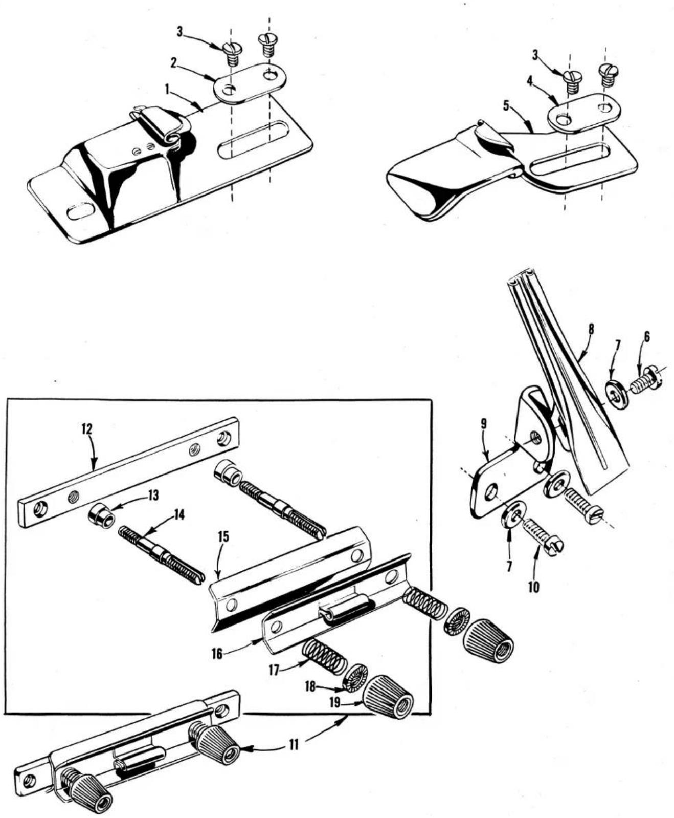
ATTACHMENTS, BRACKETS AND STRIP TENSION
| Ref.No. | PartNo. | Description | Amt.Req. |
| 1 | 23100 | Double Edge Folder and Guide, 3/64 inch capacity, 3/16 inch overlap, for Styles 56200 R - - - - - - - - - - - - - - - - - - - - - - - - - - - - - - - - - - - - - - - - - - - - - - - - - - - - - - - - - - - - - - - - - - - - - - - - - - - - - - - - - - - - - - - - - - - - - - - - - - - - | 1 |
| 2 | 23425 V | Washer Plate - - - - - - - - - - - - - - - - - - - - - - - - - - - - - - - - - - - - - - - - - - - - - - - - - - - - - - - - - - - - - - - - - - - - - - - - - - - - - - - - - - - - - - - - - - - - - - - - - - - | |
| 3 | 25 C | Screw, for attachment - - - - - - - - - - - - - - - - - - - - - - - - - - - - - - - - - - - - - - - - - - - - - - - - - - - - - - - - - - - - - - - - - - - - - - - - - - - - - - - - - - - - - - - - - - - - - - - - - - - | |
| 4 | 23425 V | Washer Plate - - - - - - - - - - - - - - - - - - - - - - - - - - - - - - - - - - - - - - - - - - - - - - - - - - - - - - - - - - - - - - - - - - - - - - - - - - - - - - - - - - - - - - - - | |
| 5 | 23405 J | Body Folder, for turning body of garment downwardly, 1/32 inch capacity, 5/16 inch fold, for Style 56400 S - - - - - - - - - - - - - - - - - - - - - - - - - - - - - - - - - - - - - - - - - - - - - - - - - - - - - - - - - - - - - - - - - - - - - - - - - - - - - - - - - - - - - - - - | |
| 6 | 22548 | Screw, for facing strip folder - - - - - - - - - - - - - - - - - - - - - - - - - - - - - - - - - - - - - - - - - - - - - - - - - - - - - - - - - - - - - - - - - - - - - - - - - - - - - - - - - - - - - - - - - - - - - - - - - - - 1 | |
| 7 | 9255 | Washer - - - - - - - - - - - - - - - - - - - - - - - - - - - - - - - - - - - - - - - - - - - - - - - - - - - - - - - - - - - - - - - - - - - - - - - - - - - - - - - - - - - - 3 | |
| 8 | 23435-32 | Facing Strip Folder, for shirt front operations, 1/32 inch capacity, uses strip 1 inch wide, finishes 5/8 inch, for No. 32 gauge, Style 56400 S - - - - - - - - - - - - - - - - - - - - - - - - - - - - - - - - - - - - - - - - - - - - - - - - - - - - - - 1 | |
| - | 23435-48 | Facing Strip Folder, for shirt front operations, 1/32 inch capacity, uses strip 1 1/4 inch wide, finishes 7/8 inch, for No. 48 gauge, Style 56400 S - - - - - - - - - - - - - - - - - - - - - - - - - - - - - - - - - - - - 1 | |
| 9 | 23436 | Folder Bracket, for Style 56400 S - - - - - - - - - - - - - - - - - - - - - - - - - - - - - - - - - - - - - - - - - - - - - - - - - - 1 | |
| 10 | 136 | Screw, for folder bracket - - - - - - - - - - - - - - - - - - - - - - - - - - - - - - - - - - - - - - - - - 2 | |
| 11 | 21182 N | Strip Tension, for Style 56400 S - - - - - - - - - - - - - - - - - - - - - - - - - - - - - - - 1 | |
| 12 | 21182 P | Strip Tension Base - - - - - - - - - - - - - - - - - - - - - - - - - - - - - - 1 | |
| 13 | 11261 B | Tension Post Ferrule - - - - - - - - - - - - - - - - - - - - - - - - - - 2 | |
| 14 | 56392 E | Tension Post - - - - - - - - - - - - - - - - - - - - - - - - 2 | |
| 15 | 21182 L | Strip Tension Plate, inner - - - - - - - - - - - - - - - - - - - 1 | |
| 16 | 21182 K | Strip Tension Plate, outer - - - - - - - - - - - - - - - - - 1 | |
| 17 | 110-3 | Tension Spring - - - - - - - - - - - - - - - - - - - 2 | |
| 18 | 39592 AK | Tension Nut Ferrule - - - - - - - - - - - - - - 2 | |
| 19 | 39592 Z | Tension Nut- - - - - - - - - - - - 2 |

text_image
Technical diagram of a mechanical assembly with numbered parts for identification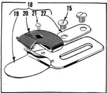
text_image
Technical diagram of a mechanical clamp or bracket with numbered parts and directional arrows indicating assembly or movement.
text_image
40 39 41 38 37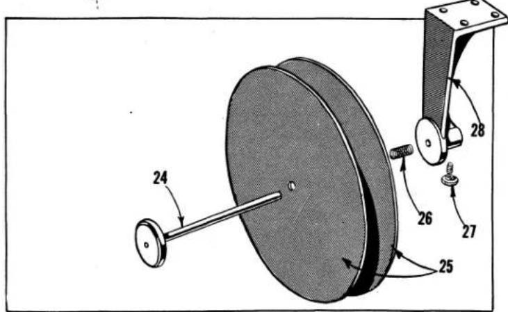
text_image
Technical diagram of a mechanical device with numbered components and directional arrows indicating motion or assembly.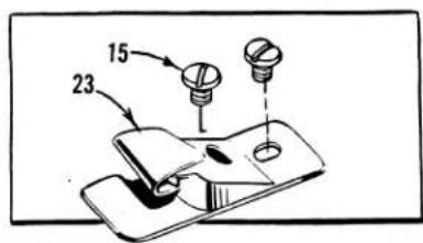
text_image
15 23
text_image
Technical diagram of a screwdriver with labeled parts including drill bit, chain, and clamp toolsATTACHMENTS, TAPE REEL AND MISCELLANEOUS ACCESSORIES
| Ref.No. | PartNo. | Description | Amt.Req. |
| 1 | 23401 K-64 | Center Plait Folder, 1/32 inch capacity, plait extends 1/4 inch beyond rows of stitches, uses plait cut 2 1/2 inches wide, finishes 1 1/2 inches; interlining strip cut 1 15/32 inches wide, for No.64 gauge, for Styles 56700 J | 1 |
| - | 23401 K-56 | Center Plait Folder, 1/32 inch capacity, plait extends 1/4 inch beyond rows of stitches, uses plait cut 2 3/8 inches wide, finishes 1 3/8 inches; interlining strip cut 1 11/32 inches wide, for No.56 gauge, for Style 56700 J | 1 |
| - | 23401-K-48 | Center Plait Folder, 1/32 inch capacity, plait extends 1/4 inch beyond rows of stitches, uses plait cut 2 1/4 inches wide, finishes 1 1/4 inches; interlining strip cut 1 7/32 inches wide, for No.48 gauge, for Style 56400 R | 1 |
| + - | K58337 | Center Plait Folder, 1/16 inch capacity, plait extends 1/4 inch beyond rows of stitches, uses plait cut 2 1/2 inches wide, finishes 1 1/2 inches; interlining strip cut 1 7/16 inches wide, for No.64 gauge, for Style 56700 J | 1 |
| * 2 | 22528 | Screw | 2 |
| * 3 | 23229 P | Folder Bracket, for Styles 56400 R, 56700 J | 1 |
| * 4 | 23229 N | Folder Swinging Arm, for Styles 56400 R, 56700 J | 1 |
| 5 | 22572 A | Screw | 2 |
| * 6 | 22773 | Screw | 1 |
| * 7 | 23229 Y | Folder Swinging Arm Support, for Styles 56400 R, 56700 J | 1 |
| * 8 | 25 T | Screw | 1 |
| * 9 | 23229 Q | Folder Clamp, for Styles 56400 R, 56700 J | 1 |
| *10 | 22863 A | Adjusting Screw | 1 |
| *11 | 25 CC | Screw | 2 |
| *12 | 22730 | Screw | 1 |
| 13 | 25 B | Screw | 2 |
| 14 | 23403-64 | Angular Interlining Guide, reversible, for No. 64 gauge, Style 56700 J | 1 |
| - | 23403-56 | Angular Interlining Guide, reversible, for No. 56 gauge, Style 56700 J | 1 |
| - | 23403-48 | Angular Interlining Guide, reversible, for No. 48 gauge, Style 56400 R | 1 |
| 15 | 25 C | Screw, for Styles 56200 K, R, 56500 J, R, 56700 J, Class 56400 and 56900 | 2 |
| 16 | 23405 L | Body Folder, for turning body of garment upwardly, 1/32 inch capacity, 5/16 inch fold, for Styles56400 R, 56700 J | 1 |
| 17 | 23425 V | Washer Plate | 1 |
| 18 | Double Lap Seam Feller Assembly (See Chart Below) | 1 | |
| 19 | Lower Scroll and Base (See Chart Below) | 1 | |
| 20 | Upper Scroll (See Chart Below) | 1 | |
| 21 | 28 | Screw | 1 |
| 22 | 23425 V | Washer Plate | 1 |
| 28 | Screw, for Ref. No. 20 on Styles 56900 P-9, R-9 (not shown) | 1 | |
| 23425 V | Washer Plate, for Styles 56900 P-9, R-9 (not shown) | 1 | |
| 23 | 23151 A | Plate Folder and Guide, for heavy materials, 1/4 inch capacity for both plies, top ply folded,lower ply flat, 1/2 inch overlap, for Style 56900 J | 1 |
| 24 | 21385 B | Tape Reel Axle, for Styles 56400 R, 56700 J | 1 |
| 25 | 21178 | Tape Reel Disc, for Styles 56400 R, 56700 J | 2 |
| 26 | 110-3 | Tape Reel Spring, for Styles 56400 R, 56700 J | 1 |
| 27 | 201 C | Tape Reel Axle Screw, for Styles 56400 R, 56700 J | 1 |
| 28 | 201 A | Tape Reel Frame, for Styles 56400 R, 56700 J | 1 |
| 29 | 21201 | Screwdriver, 9/64 inch round blade, length overall 7 11/16 inches, for Classes 56400, 56500, 56700,56900- | 1 |
| 30 | 660-240 | Thread Tweezers, for all Styles | 1 |
| 31 | 116 | Wrench, 9/32 inch open end, for Classes 56200, 56300 | 1 |
| 32 | 21388 | Wrench, 3/8 inch open end, for all Styles | 1 |
| 33 | 660-264 | "S" Hook, for all Styles | 2 |
| 34 | 421 D-34 | Treadle Chain, 34 inches long, for all Styles | 1 |
| 35 | 51295 A | Isolator | 1 |
| 36 | 51295 B | Isolator | 3 |
| 37 | SC303 | Wood Screw, #12, 1 inch long, for Styles 56200 K, L, 56300 M | 2 |
| 38 | 21169 F | Binding Holder Base, for Styles 56200 K, L, 56300 M | 1 |
| 39 | 161 | Binding Holder Stop Collar, for Styles 56200 K, L, 56300 M | 1 |
| 40 | 88 | Screw | 1 |
| 41 | 21169 E | Binding Holder Disc, for Styles 56200 K, L, 56300 M | 1 |
DOUBLE LAP SEAM FELLER
| Assembly No.Ref. No. 18 | Lower ScrollRef. No. 19 | Upper ScrollRef. No. 20 | Gauge | Capacity | For Machine Style |
| 23420 U-6-1/32 | 23422 U-1/32 | 23421 U-6-1/32 | 6 | 1/32" | 56400 P-6 |
| 23420 U-8-1/32 | 23422 U-1/32 | 23421 U-8-1/32 | 8 | 1/32" | 56400 P-8, W-8 |
| 23420 U-10-1/32 | 23422 U-1/32 | 23421 U-10-1/32 | 10 | 1/32" | 56400 P-10, W-10 |
| 23420 U-12-1/16 | 23422 U-1/16 | 23421 U-12-1/16 | 12 | 1/16" | 56400 P-12, W-12 |
| 23420 U-16-1/16 | 23422 U-1/16 | 23421 U-16-1/16 | 16 | 1/16" | 56400 P-16, W-16 |
| 23420 U-16-3/32 | 23422 U-3/32 | 23421 U-16-3/32 | 16 | 3/32" | 56500 J-16, 56900 H-7, H-8 |
| 23420 U-18-1/16 | 23422 U-1/16 | 23421 U-18-1/16 | 18 | 1/16" | 56400 P-18 |
| 23420 U-18-3/32 | 23422 U-3/32 | 23421 U-18-3/32 | 18 | 3/32" | 56500 J-18, R-18, 56900 H-9 |
| +23420 U-18-1/8 | 23422 U-1/8 | 23421 U-18-1/8 | 18 | 1/8" | |
| 23420 U-26-1/16 | 23422 U-1/16 | 23421 U-26-1/16 | 26 | 1/16" | 56400 X-26 |
| 23420 V-8-1/32 | 23422 V-1/32 | 23421 V-8-1/32 | 8 | 1/32" | 56400 T-8 |
| 23420 V-10-1/32 | 23422 V-1/32 | 23421 V-10-1/32 | 10 | 1/32" | 56400 T-10 |
| 23420 V-12-1/32 | 23422 V-1/32 | 23421 V-12-1/32 | 12 | 1/32" | 56400 T-12 |
| 23420 V-16-1/32 | 23422 V-1/32 | 23421 V-16-1/32 | 16 | 1/32" | 56400 T-16 |
| - | 23422 BZ-3/32 | 23421 U-18-3/32 | 9 | 3/32" | 56900 P-9 |
| - | 23422 BZ-1/8 | 23421 U-18-1/8 | 9 | 1/8" | 56900 R-9 |
- Available as an extra send and charge item or on special machines.
* Available complete as part No. 29481 D (Suspended Folder Arm Assembly).
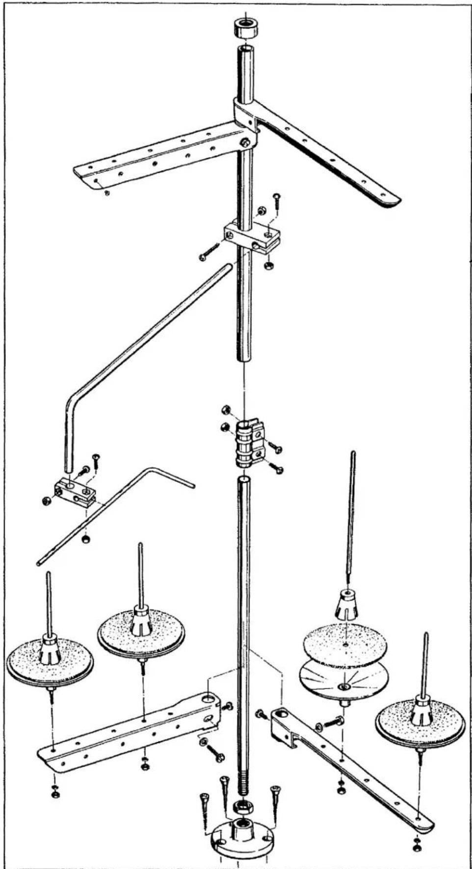
text_image
Technical diagram of a mechanical assembly with labeled components and structural detailsTHREAD STAND PARTS
| Ref. No. | Part No. | Description | Amount Required | ||
| One Needle | Two Needle | Three Needle | |||
| 1 | 21101W4 | Thread Stand, complete, for Classes 56400, 56500, 56700- | 1 | 1 | 1 |
| - | 21101W2 | Thread Stand, complete, for Classes 56200, 56300 - - - - | |||
| - | 21101W6 | Thread Stand, complete, for Class 56900 - - - - - - - | |||
NUMERICAL INDEX OF PARTS
| Part No. | Page No. | Part No. | Page No. | Part No. | Page No. |
| SC2 | 55 | 201 C | 69 | 11638 M | 25 |
| W03 | 29,31 | 258 A | 31,33,71 | 12934 A | 29,55 |
| NU12 | 55 | 269 | 31,33 | 12935 A | 63 |
| 18 | 31 | SC303 | 69 | 12957 E | 41 |
| 20 | 25,31,35 | 402 | 39 | 14077 | 31 |
| CL21 | 29 | 421 D-34 | 69 | 15438 C | 25 |
| 24 | 41 | 531 | 39 | 15465 F | 31 |
| 24 S | 41 | 539 | 25 | 19146 A | 47,49,53 |
| 25 | 41 | 604 | 47,49,51, | 21101 H | 71 |
| 25 B | 69 | 53,57 | 21104 B-24 | 71 | |
| 25 C | 41,67,69 | 605 | 57 | 21104 H | 71 |
| 25 S | 69 | 605 A | 25,43 | 21104 V | 71 |
| 25 T | 69 | 652-16 | 71 | 21114 | 71 |
| 25 CC | 69 | 660-73 | 25 | 21114 A | 71 |
| 25 TB | 41 | 660-74 | 25 | 21114 D | 71 |
| 27-435 Blk | 29 | 660-75 | 25 | 21114 H | 71 |
| 28 | 35,47,69 | 660-202 | 29 | 21114 S | 71 |
| 50-216 Blk | 35 | 660-207 | 39 | 21114 T | 71 |
| 50-458 Blk | 31 | 660-215 | 29 | 21114 U | 71 |
| 50-895 Blk | 27 | 660-221 | 27 | 21114 W | 71 |
| 50 J | 43 | 660-240 | 69 | 21169 E | 69 |
| 52 A | 25 | 660-264 | 69 | 21169 F | 69 |
| 56 | 29,43 | 660-269 B | 33 | 21178 | 69 |
| 57 WB | 25 | 660-310 | 31 | 21182 K | 67 |
| 57 WD | 25,57 | 660-313 | 25 | 21182 L | 67 |
| 65 XD | 51 | 660-342 | 25 | 21182 N | 67 |
| C067 D | 39 | 660-406 | 55 | 21182 P | 67 |
| C067 E | 31 | 660-437 | 55 | 21201 | 69 |
| 73 | 31,45 | 660-438 | 33 | 21210 | 45 |
| 73 A | 45,51,55,57,61,63,65 | 660-455 | 27 | 21210 A | 45 |
| 660-614 | 29 | 21375 AV | 25 | ||
| 660-617 | 25 | 21385 B | 69 | ||
| HA73 B | 55 | 660-625 | 29 | 21388 | 69 |
| 77 | 29,33,61,65 | 660-665 | 27,29 | 21396 AG | 25 |
| 666-149 | 33 | 21396 AL | 25 | ||
| 86 X | 51 | 666-214 | 25 | 21396 BK | 25 |
| 87 | 25 | 666-259 | 27 | 21396 BP | 25 |
| 87 U | 31,47 | 719 | 31 | 21396 BR | 25 |
| 88 | 31,51,55,57,69 | 1096 | 47,49 | 21657-3 | 37 |
| 1280 | 31 | 21657-4 | 37 | ||
| 88 B | 43 | 1594 A | 47,49 | 21657 E | 33,35,41 |
| 89 | 43 | 1740 | 59,61 | 21657 W | 39 |
| 90 | 27,41 | 1741 A | 51 | 21657 X | 27 |
| 91 | 47,49,51,53,57,59,61,63,65 | 1741 B | 47,51,53,57 | 21657 Y | 39 |
| 6042 A | 33 | 22513 | 25 | ||
| 91 A | 59,61,65 | 6405 M | 49 | 22513 B | 43 |
| 91 D | 65 | 6420 W | 49 | 22524 | 25 |
| 95 | 25,29 | 6430 | 49 | 22525 A | 33 |
| 96 | 31 | 6430 A | 49 | 22526 C | 41 |
| 98 | 31,33,43 | 7018 E-5 | 43 | 22528 | 33,35,69 |
| 98 A | 25,35 | 7040-6 | 43 | 22537 | 39 |
| 109 | 37 | 7420 AG-4 1/2 | 57 | 22539 R | 27 |
| 110-3 | 67,69 | 7947 | 25 | 22541 C | 27 |
| 116 | 69 | 9205 E | 47 | 22543 A | 33 |
| 136 | 67 | 9224 E | 47,49 | 22548 | 25,67 |
| 158 A | 25 | 9255 | 67 | 22557 G | 39 |
| 158 B | 35 | 9634 | 57 | 22559 A | 29 |
| 161 | 69 | 9634 A | 57 | 22559 G | 29 |
| SC178 | 55 | 9705 | 57 | 22560 B | 51,57 |
| SC180 | 55 | 9720 | 57 | 22561 | 47,49 |
| 187 A | 51,53,61 | 9724 | 57 | 22561 D | 65 |
| 187 B | 43,47,51,57 | 9735 | 57 | 22562 A | 29 |
| 11261 B | 67 | 22564 B | 25,27 | ||
| 201 A | 69 | 11635 B | 27 | 22569 C | 25 |
NOTE: Only the basic part numbers are shown in the index. For various gauges, capacities, etc. available, refer to the listings on pages indicated.
NUMERICAL INDEX OF PARTS
| Part No. | Page No. | Part No. | Page No. | Part No. | Page No. |
| 22570 | 25 | 22882 C | 31 | 35820 P | 63 |
| 22572 A | 69 | 22889 A | 25 | 35820 S-9 | 65 |
| 22574 | 29 | 22891 B | 33 | 35830 | 59,63 |
| 22580 | 43 | 22894 C | 29 | 35830 B | 65 |
| 22580 D | 33 | 22894 D | 29 | 35830 C | 65 |
| 22585 | 25,41 | 22894 E | 25 | 35830 D | 65 |
| 22585 A | 25 | 22894 J | 29 | 35830 F | 65 |
| 22586 R | 29 | 22894 P | 43 | 35830 H | 65 |
| 22587 K | 29 | 22894 AA | 33 | 35830 J | 65 |
| 22596 | 39 | 22894 AB | 29 | 35830 K | 65 |
| 22598 C | 37 | 23100 | 67 | 35830 P | 63 |
| 22599 | 65 | 23151 A | 69 | 35830 R-9 | 65 |
| 22637 P-24 | 33 | 23215 BG | 41 | 35830 S-9 | 65 |
| 22651 CB-4 | 33 | 23229 N | 69 | 35830 AE | 65 |
| 22651 CD | 33,71 | 23229 P | 69 | 35897 BV | 27 |
| 22653 L-8 | 29 | 23229 Q | 69 | 39543 N | 33 |
| 22729 | 43 | 23229 Y | 69 | 39552 C | 39 |
| 22729 C | 31 | 23322 AB | 41 | 39592 Z | 37,67 |
| 22733 C | 25 | 23322 AC | 41 | 39592 AK | 37,67 |
| 22733 E | 27 | 23401 K | 69 | 41047 | 31 |
| 22735 | 41 | 23403 | 69 | 41071 G | 51,57 |
| 22738 | 47,49 | 23405 J | 67 | 41391 | 33 |
| 22743 | 43 | 23405 L | 69 | 43266 | 37 |
| 22752 | 43 | 23420 U | 69 | 43296 | 25 |
| 22752 B | 61,65 | 23420 V | 69 | 51054 | 33 |
| 22758 C | 39 | 23421 U | 69 | 51154 E | 27 |
| 22758 G | 47 | 23421 V | 69 | 51170 D | 31 |
| 22760 A | 41 | 23422 U | 69 | 51205 A | 49 |
| 22764 C | 33 | 23422 V | 69 | 51205 R | 47 |
| 22768 | 29,35 | 23422 BZ | 69 | 51205 W | 57 |
| 22773 | 69 | 23425 T | 41 | 51208 | 45 |
| 22785 | 51,57 | 23425 V | 41,67,69 | 51208 D | 45 |
| 22793 | 27 | 23435 | 67 | 51208 W | 45 |
| 22798 C | 33 | 23436 | 67 | 51210 | 45 |
| 22799 B | 51,53,59,61,63 | 23437 B | 41 | 51216 M | 29 |
| 23437 Y | 41 | 51216 N | 29,31 | ||
| 22799 C | 59,61,63 | 23438 A | 41 | 51216 P | 29 |
| 22799 D | 61,65 | 23438 B | 41 | 51217 C | 43 |
| 22799 E | 49,57,59,61,63 | 23439 A | 41 | 51220 A | 49 |
| 29066 R | 29 | 51220 W | 57 | ||
| 22799 G | 53,57,61,63 | 29105 AK | 29 | 51224 A | 49 |
| 29105 AL | 29 | 51224 B | 49 | ||
| 22799 L | 65 | 29192 V | 31 | 51230 F | 57 |
| 22799 R | 55 | 29192 W | 31 | 51230 G | 57 |
| 22801 | 33,43 | 29192 X | 31 | 51236 A | 31,33 |
| 22810 | 71 | 29192 Y | 31 | 51240 D | 31 |
| 22829 | 25,31 | 29192 AA | 31 | 51242 M | 31 |
| 22834 A | 33 | 29202 L-1 | 43 | 51244 L | 31 |
| 22835 | 31 | 29202 M-1 | 43 | 51244 N | 31 |
| 22836 | 25 | 29202 N-1 | 43 | 51246 | 31 |
| 22837 | 35 | 29348 AF | 29 | 51247 | 29 |
| 22839 | 25 | 29476 LL | 29 | 51250 D | 29 |
| 22839 C | 41 | 29476 LM | 29 | 51250 F | 29 |
| 22840 A | 49,57,59,63 | 29476 LN | 29 | 51254 K | 29 |
| 29476 LV | 31 | 51256 C | 39 | ||
| 22840 C | 39 | 29476 MJ | 33 | 51257 K | 39 |
| 22845 A | 65 | 29476 MY | 35 | 51257 M | 39 |
| 22845 B | 41 | 29476 NM | 33 | 51257 AA | 27 |
| 22848 | 25,35 | 35730 AB | 63 | 51270 B | 25 |
| 22848 A | 55 | 35730 AC | 61,63 | 51280 J | 25 |
| 22863 A | 69 | 35730 AD | 61,63 | 51281 AC | 41 |
| 22863 C | 33 | 35730 AE | 61,63 | 51283 H | 39 |
| 22874 | 31 | 35731 A | 25 | 51292 A | 37 |
| 22875 H | 33 | 35772 H | 41 | 51292 D | 37 |
| 22875 J | 47 | 35818 N | 43 | 51292 F | 37 |
NOTE: Only the basic part numbers are shown in the index. For various gauges, capacities, etc. available, refer to the listings on pages indicated.
NUMERICAL INDEX OF PARTS
| Part No. | Page No. | Part No. | Page No. | Part No. | Page No. | |||
| 51294 | R. | 25 | 51420. | 59 | 51905 | B-9. | 63 | |
| 51295 | A. | 69 | 51420 | C. | 61 | 51905 | E-9. | 65 |
| 51295 | B. | 69 | 51420 | E. | 63 | 51908 | B. | 45 |
| 51305 | B. | 51 | 51420 | K. | 61 | 51909 | C. | 45 |
| 51305 | U. | 51 | 51420 | R. | 63 | 51909 | D. | 45 |
| 51305 | V. | 55 | 51420 | AD-12. | 57 | 51917 | A. | 43 |
| 51305 | W. | 49,51,57 | 51424. | 59 | 51918-7. | 43 | ||
| 51320 | B. | 51 | 51424 | A. | 59 | 51920-7. | 63 | |
| 51320 | J. | 51 | 51424 | B. | 61 | 51924 | A-7. | 63 |
| 51320 | M. | 47 | 51424 | C-48. | 61 | 51924 | B. | 63 |
| 51320 | N. | 51 | 51424 | E. | 63 | 51924 | E-9. | 65 |
| 51320 | W. | 49 | 51424 | K. | 61 | 51930. | 59,63 | |
| 51324 | B. | 51 | 51424 | R. | 63 | 51930 | A. | 63 |
| 51324 | F. | 47,49 | 51424 | AD. | 57 | 51930 | B-7. | 63 |
| 51324 | K. | 47 | 51430. | 61,65 | 51957 | D. | 39 | |
| 51324 | V. | 55 | 51430 | A. | 59 | 51957 | E. | 39 |
| 51324 | W. | 49,51,57 | 51430 | B. | 61 | 51959 | B. | 35 |
| 51326 | A. | 49 | 51430 | C. | 61 | 51959 | D. | 35 |
| 51327 | A. | 49 | 51430 | D. | 57,59,63 | 51959 | J. | 35 |
| 51330 | B. | 51 | 51430 | E. | 63 | 51959 | K. | 35 |
| 51330 | M. | 47,49 | 51430 | F. | 39,49,51, | 51992 | A. | 37 |
| 51330 | N. | 47 | 57,59,63 | 52336 | A. | 29 | ||
| 51330 | P. | 47,49 | 51430 | K. | 61 | 52804 | A. | 35 |
| 51330 | R. | 47,49 | 51430 | R. | 63 | 52889 | A. | 39 |
| 51330 | S. | 47 | 51457 | A. | 35 | 52892. | 37 | |
| 51330 | W. | 47,51 | 51459 | A. | 35 | 52930 | AC. | 51,57,59, |
| 51330 | X. | 51 | 51491 | C. | 37 | 61 | ||
| 51330 | Y. | 51 | 51492. | 35 | 52942 | R. | 31 | |
| 51330 | Z. | 47,49 | 51505-18. | 59 | 52942 | W. | 27 | |
| 51330 | AB. | 47,49 | 51505 | BR-18. | 61 | 52942 | AA. | 29 |
| 51330 | AD. | 47 | 51508 | C-1. | 45 | 52942 | AC. | 27,29 |
| 51330 | AE. | 47,49 | 51508 | G-1. | 45 | 52958 | B. | 25 |
| 51330 | AG. | 47 | 51508 | H-1. | 45 | 52958 | G. | 25 |
| 51330 | AH. | 47 | 51508 | M. | 45 | 53530 | E. | 61 |
| 51330 | AJ. | 47 | 51509 | C. | 45 | 53783 | N. | 39 |
| 51330 | AK. | 51 | 51518 | C-1. | 43 | 53787. | 39 | |
| 51330 | AL. | 51 | 51518 | G-1. | 43 | 55235 | D. | 33 |
| 51330 | AM. | 51 | 51520. | 59 | 55235 | E. | 33 | |
| 51330 | AX. | 49 | 51520 | BR-18. | 61 | 55244 | G. | 31 |
| 51330 | BB. | 49 | 51524. | 59 | 56122 | A. | 33 | |
| 51330 | BC. | 55 | 51524 | BR-18. | 61 | 56190. | 27 | |
| 51330 | BD. | 55 | 51530. | 59 | 56205. | 51 | ||
| 51330 | BE. | 55 | 51530 | D. | 59,61 | 56224. | 51 | |
| 51330 | BF. | 55 | 51530 | F. | 59,61 | 56224 | A. | 57 |
| 51334 | A. | 47 | 51530 | G. | 59,61 | 56224 | H. | 47 |
| 51334 | C. | 47 | 51530 | J. | 61 | 56301. | 41 | |
| 51334 | D. | 47 | 51530 | BR-18. | 61 | 56301 | A. | 41 |
| 51405-16. | 59 | 51557. | 35 | 56304. | 35 | |||
| 51405 | A. | 59 | 51704. | 35 | 56305. | 47 | ||
| 51405 | B. | 61 | 51705. | 65 | 56305 | AL. | 47 | |
| 51405 | C-48. | 61 | 51708. | 45 | 56313. | 31 | ||
| 51405 | G. | 63 | 51709. | 45 | 56315 | A. | 29 | |
| 51405 | K-26. | 61 | 51717. | 43 | 56316. | 29 | ||
| 51405 | R. | 63 | 51718 | A. | 43 | 56316 | C. | 29 |
| 51405 | AD. | 57 | 51718 | B. | 43 | 56320. | 47 | |
| 51408. | 45 | 51720. | 65 | 56320 | A. | 55 | ||
| 51409. | 45 | 51724. | 65 | 56320 | B. | 53 | ||
| 51409 | B. | 45 | 51730. | 65 | 56320 | C. | 53 | |
| 51409 | C. | 45 | 51730 | A. | 65 | 56320 | D. | 53 |
| 51417 | C. | 43 | 51745. | 31 | 56320 | F. | 51 | |
| 51417 | D. | 43 | 51757 | B. | 35 | 56320 | G. | 53 |
| 51418-16. | 43 | 51758. | 25 | 56320 | H. | 57 | ||
| 51418 | B-32. | 43 | 51770. | 31 | 56320 | U. | 47 | |
| 51418 | D-48. | 43 | 51771. | 31 | 56321 | D. | 29 | |
| 51418 | K. | 43 | 51905 A-7. | 63 | 56321 | N. | 29 |
NOTE: Only the basic part numbers are shown in the index. For various gauges, capacities, etc. available, refer to the listings on pages indicated.
NUMERICAL INDEX OF PARTS
| Part No. | Page No. | Part No. | Page No. | Part No. | Page No. | |||
| 56322 | B. | 33 | 56350 | F. | 29 | 56505 | A. | 61 |
| 56322 | C. | 33 | 56350 | G. | 29 | 56505 | B. | 59 |
| 56323 | 33 | 56354 | C. | 27 | 56513 | 31 | ||
| 56324 | AL. | 47 | 56354 | D. | 29 | 56517 | B. | 43 |
| 56325 | 43 | 56356 | 39 | 56517 | C-1. | 43 | ||
| 56330 | 47,49 | 56357 | A. | 39 | 56517 | D-1. | 43 | |
| 56330 | E. | 47,49 | 56358 | 29 | 56517 | E-1. | 43 | |
| 56330 | F. | 47,49 | 56358 | A. | 29 | 56518 | C-1. | 43 |
| 56330 | G. | 47,49 | 56358 | B. | 35 | 56520 | 59,61 | |
| 56330 | H. | 55 | 56358 | C. | 35 | 56524 | A-1. | 59 |
| 56330 | J. | 55 | 56358 | D. | 35 | 56524 | B-1. | 59 |
| 56330 | K. | 55 | 56358 | E. | 35 | 56525 | 43 | |
| 56330 | L. | 55 | 56370 | 25 | 56525 | A. | 43 | |
| 56330 | M. | 55 | 56380 | 25 | 56525 | B. | 43 | |
| 56330 | N. | 55 | 56381 | 41 | 56525 | C. | 43 | |
| 56330 | P. | 53 | 56381 | C-207. | 41 | 56528 | 59,61 | |
| 56330 | R. | 53 | 56381 | E-207. | 41 | 56528 | B-1. | 61 |
| 56330 | S. | 53 | 56382 | 25 | 56528 | C-1. | 59 | |
| 56330 | T. | 53 | 56382 | B. | 27 | 56530 | 59,61 | |
| 56330 | U. | 53 | 56382 | C. | 27 | 56530 | A. | 59,61 |
| 56330 | V. | 53 | 56382 | D. | 25 | 56701 | 41 | |
| 56330 | W. | 53 | 56382 | E. | 25 | 56713 | 31 | |
| 56330 | X. | 53 | 56382 | G. | 25 | 56722 | E. | 33 |
| 56330 | Y. | 53 | 56382 | H. | 25 | 56723 | 33 | |
| 56330 | AA. | 53 | 56382 | J. | 25 | 56725 | 43 | |
| 56330 | AB. | 51 | 56382 | K. | 25 | 56744 | 31 | |
| 56330 | AD. | 51,57 | 56382 | L. | 25 | 56744 | A. | 31 |
| 56330 | AE. | 51 | 56382 | M. | 27 | 56751 | 31 | |
| 56330 | AF. | 51,57 | 56382 | N. | 25 | 56772 | 31 | |
| 56330 | AG. | 51,57 | 56382 | X. | 37 | 56782 | 25 | |
| 56330 | AH. | 51,57 | 56382 | Y. | 25 | 56905 | A-9. | 65 |
| 56330 | AJ. | 51,57 | 56382 | AA. | 25 | 56913 | 31 | |
| 56330 | AK. | 51,57 | 56382 | AB. | 25 | 56913 | A. | 31 |
| 56330 | AL. | 57 | 56382 | AC. | 27 | 56917 | 43 | |
| 56330 | AM. | 57 | 56383 | A. | 39 | 56920 | A-9. | 65 |
| 56330 | AN. | 57 | 56383 | D. | 39 | 56924 | A-9. | 65 |
| 56330 | AP. | 51,57 | 56383 | AA. | 39 | 56925 | 43 | |
| 56330 | AR. | 57 | 56383 | AB. | 39 | 56930 | 65 | |
| 56330 | AU. | 51,57 | 56390 | 27 | 56958 | 29 | ||
| 56330 | AX. | 51,57 | 56390 | E. | 27 | 56958 | A. | 29 |
| 56334 | B. | 33 | 56390 | G. | 27 | 56958 | B. | 25 |
| 56334 | F. | 47 | 56390 | H. | 27,29 | 57835 | B. | 27 |
| 56334 | L. | 33 | 56390 | J. | 27,29 | 57840 | 31 | |
| 56334 | N. | 33 | 56391 | 25 | 57841 | 31 | ||
| 56334 | P. | 33 | 56392 | E. | 37,67 | 57841 | A. | 31 |
| 56335 | D. | 33 | 56392 | F. | 37 | 57842 | B. | 27 |
| 56335 | G. | 33 | 56393 | C. | 25 | 57847 | 29 | |
| 56335 | L. | 33 | 56393 | D. | 25 | 57890 | B. | 27 |
| 56336 | 33 | 56393 | J. | 31 | 57954 | 27 | ||
| 56336 | B. | 33 | 56393 | L. | 27 | K58337 | 69 | |
| 56336 | C. | 33 | 56393 | P. | 27 | 59292 | 37 | |
| 56336 | D. | 33 | 56393 | Q. | 27 | 59292 | A. | 37 |
| 56341 | E. | 31 | 56393 | T. | 27 | 59493 | A. | 25 |
| 56341 | F. | 31 | 56393 | W. | 27 | 61256 | G. | 27 |
| 56341 | G. | 31 | 56394 | A. | 27 | 61321 | L. | 29 |
| 56341 | M. | 31 | 56394 | B. | 27 | 61341 | J. | 33 |
| 56342 | D. | 27 | 56394 | C. | 27 | 61430 | AJ. | 55 |
| 56342 | E. | 29,31 | 56401 | 41 | 61430 | AN. | 55 | |
| 56343 | C. | 29 | 56413 | 31 | 61430 | BT. | 47,49,53 | |
| 56343 | E. | 29 | 56423 | 33 | 61434 | G. | 33 | |
| 56343 | F. | 29 | 56425 | 43 | 63494 | F. | 27 | |
| 56344 | 31 | 56458 | 29 | 63494 | G. | 27 | ||
| 56344 | B. | 31 | 56458 | A. | 29 | 63494 | K. | 27 |
| 56344 | C. | 31 | 56470 | 25 | 80557 | 37 | ||
| 56350 | D. | 29 | 56480 | 25 | ||||
| 56350 | E. | 29 | 56505 | 59 |
NOTE: Only the basic part numbers are shown in the index. For various gauges, capacities, etc. available, refer to the listings on pages indicated.
Union Special Corporation
Corporate Office
One Union Special Plaza
Huntley, IL 60142
Phone: 847·669·5101
Fax: 847·669·4454
Union Special GmbH
EuropeanDistributionCenter
Raiffeisenstrasse 3
D-71696 Möglingen, Germany
Tel: 49·07141·247·0
Fax: 49·07141·247·100
JUKI CORPORATION
INTERNATIONAL SALES DIVISION
8-2-1, KOKURYO - CHO,