MFC7000-UT4 - Sewing machine Union Special - Free user manual and instructions
Find the device manual for free MFC7000-UT4 Union Special in PDF.

User questions about MFC7000-UT4 Union Special
0 question about this device. Answer the ones you know or ask your own.
Ask a new question about this device
Download the instructions for your Sewing machine in PDF format for free! Find your manual MFC7000-UT4 - Union Special and take your electronic device back in hand. On this page are published all the documents necessary for the use of your device. MFC7000-UT4 by Union Special.
USER MANUAL MFC7000-UT4 Union Special
Thread Trimmer, Autolifter, Wiper (Pneumatic, Solenoid) for MFC-7000 Series
MFC-7000 Series
UT1 • UT2 • UT3 • UT4 • UT5
ADJUSTING INSTRUCTIONS & PARTS LIST
HOW TO MAKE USE OF THIS PARTS LIST
- Codes on the "Amt. Req." column
• Each numeral indicates the number of parts required. - "0.1" and "2.5" indicate the length (in meters) of the respective parts.
- Parentheses mean that the corresponding part is a subpart that constructs an assembly part.
- Dotted lines on the Figures indicate assembly parts
USE IN CONJUNCTION WITH MACHINE SERIAL NUMBER PREFIX BG AND LATER
| 2017 | 2016 | |
| Cost of sales | 3,458 | 3,394 |
| Gross profit | 1,000 | 1,000 |
| Net profit | 1,000 | 1,000 |
| Earnings per share: | ||
| (£) | (£) | (£) |
| Weighted average number of shares outstanding | 1.00 | 1.00 |
| Weighted average number of shares outstanding (in thousands) | 1.00 | 1.00 |
| Weighted average number of shares outstanding (in thousands, except per share amounts) | 1.00 | 1.00 |
| Weighted average number of shares outstanding (in thousands, except per share amounts) | 1.00 | 1.00 |
| Weighted average number of shares outstanding (in thousands, except per share amounts) | 1.00 | 1.00 |
| Weighted average number of shares outstanding (in thousands, except per share amounts) | 1.00 | 1.00 |
NUMERICAL INDEX OF PARTS
Part No. Page No.
| US-0050392-AN | 17 |
| US-0050392-AR | 17 |
| US-0050392-AS | 17 |
| US-0050392-AU | 17 |
| US-0050392-AV | 17 |
| US-0050394-AJ | 37 |
| US-00670E8-15 | 25, 31 |
| US-00671A3-60 | 35 |
| US-00671A3-63 | 39 |
| US-00671F8-2F | 39 |
| US-00671F8-2G | 39 |
| US-0099591-DN | 33 |
| US-0099591-DP | 23 |
| US-0099683-CP | 29 |
| US-029480-SU | 29 |
| US-029480A-TW | 31 |
| US-029480A-WU | 29 |
| US-029480A-XA | 29 |
| US-029480A-XJ | 35 |
| US-029480A-YH | 19 |
| US-029480A-YJ | 19 |
| US-0660Z10-99 | 35 |
| US-0660Z11-05 | 39 |
| US-0666Z3-30 | 17 |
| US-0670E13-02 | 25, 31 |
| US-067E150-8 | 25 |
| WP-0450846-SP | 27, 39 |
| WS-0410002-KP | 39 |
| WS-0510002-KP | 21, 35 |
| WS-0631510-KP | 21 |

JUKI CORPORATION
INTERNATIONAL SALES DIVISION
8-2-1, KOKURYO - CHO,
To order or for further
information
please contact:
* The description covered in this parts list is subject to change for improvement of the commodity without notice.
* This parts list is edited in accordance with the product specifications as of September 1997.
CONTENTS
TENSION RELEASE (UNDERBED THREAD TRIMMER) 3
THREAD PULL-OFF 4
THREADING DIAGRAM 5
UNDERBED THREAD TRIMMER (ELECTRIC) 6
UNDERBED THREAD TRIMMER ASSEMBLY 7
UNDERBED THREAD TRIMMER ASSEMBLY 8
UNDERBED THREAD TRIMMER ASSEMBLY 9
UPPER KNIFE AND CLAMPING SPRING....9
TENSION SPRING 9
UNDERBED THREAD TRIMMER ASSEMBLY 10
LOWER KNIFE FRONT TO BACK 10
STOP DISTANCE....10
GUIDE DISTANCE 10
UNDERBED THREAD TRIMMER....11
ELECTROPNEUMATIC DRIVE 11
SETTING PROXIMITY SWITCH 12
SOLENOID/PNEUMATIC THREAD WIPER 13
ADJUSTING THREAD WIPER....14
PNEUMATIC/ELECTRIC COVER THREAD TRIMMER 15
NEEDLE THREAD BLOWER ASSEMBLY 15
AIR FLOW 15
THREAD TENSION 17
UNDERBED THREAD TRIMMER ASSEMBLY 19
ELECTRIC PRESSER FOOT LIFTER ASSEMBLY 21
ELECTRIC THREAD WIPER ASSEMBLY 23
ELECTRIC DRIVE DOUBLE ACTION ASSEMBLY 25
ELECTRIC SPREADER THREAD TRIMMER ASSEMBLY 27
PNEUMATIC CONTROL 29
PNEUMATIC DRIVE DOUBLE ACTION ASSEMBLY 31
PNEUMATIC THREAD WIPER ASSEMBLY 33
PRESSER FOOT LIFTER 35
NEEDLE THREAD BLOWER ASSEMBLY 37
PNEUMATIC SPREADER THREAD TRIMMER ASSEMBLY 39
NUMERICAL INDEX OF PARTS 40
NUMERICAL INDEX OF PARTS 41

TENSION RELEASE (UNDERBED THREAD TRIMMER)
Set separators (C) as close to tension discs (D) without touching them and not to bind when fully extended.
Tension discs (D) must open as soon as cutting process begins.
Tension disc separators (C) should move freely between tension discs (D) without binding.
Thread trimmer and tension release assemblies are linked together.
text_image
Technical diagram of a mechanical assembly with labeled components A, B, and ETO ADJUST:
Loosen screw (E).
Turn eccentric (F), located behind screw (E) to set tension release lever (B) as required.
Retighten screw (E).
After adjustment there should be no binding at any point.
Adjust the tension release lever (A) to fully open the tension release and return without binding. The tension release is timed with the activation of the fabric thread trimmer.
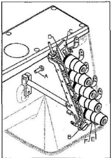
THREAD PULL-OFF
Pull-off hooks (B) for needle threads, control length of needle thread tails on a garment after trimming.
Set hooks (B) to strike-off shortest tail possible and still start sewing within the first or second stitch.
Set thread pull-off hook (C), for spreader thread so that thread is clamped securely when trimmed and starts properly when the stitch is first started. Lowering the needle thread pull off hooks will strike off more thread leaving longer tails.
Set hook (D), for the looper thread so that the thread is clamped securely when trimmed.
NOTE: Moving strike-off hooks down strikes off more thread. Moving strike-off hooks up strikes off less thread.

text_image
Technical diagram of a mechanical device with labeled components A, B, C, and D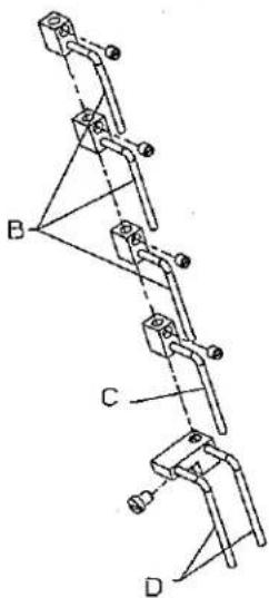
text_image
Technical diagram showing mechanical linkage or assembly with labeled components A, B, C, and DTHREADING DIAGRAM Looper Thread Strike-Off
CAUTION: Improper threading may cause; looper thread wrap-ups or inconsistent start of stitches.
natural_image
Technical line drawing of a mechanical assembly with no visible text or symbolsUNDERBED THREAD TRIMMER (ELECTRIC)
Set stroke of the driving solenoid to: 45/64" (18mm). All gauges.
Remove the cloth plate.
Loosen nut (A).
Move crosshead (B) on shaft (C) as required.
Retighten nut (A).

text_image
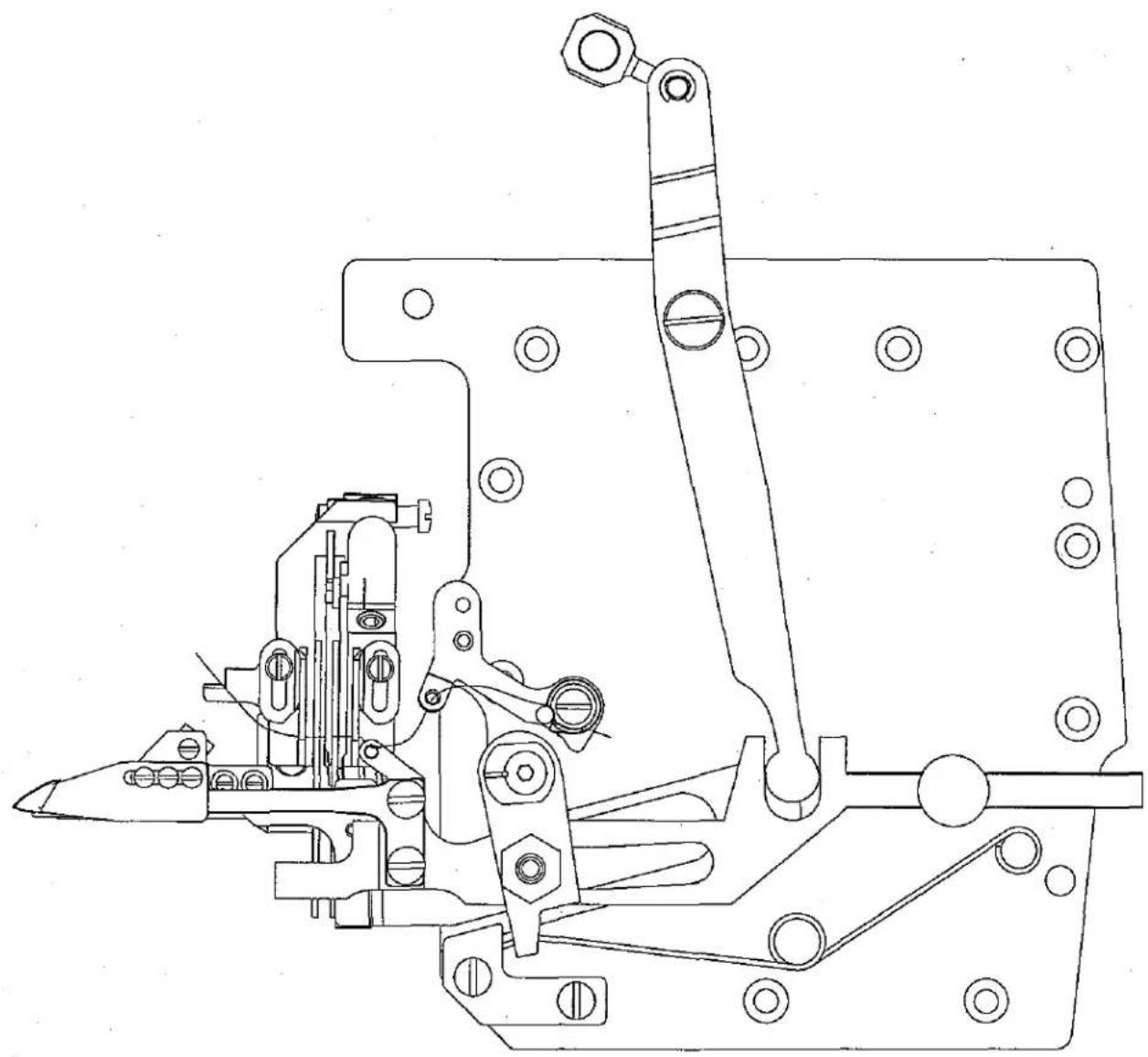
45/64" (18mm) All Gauges A B CUNDERBED THREAD TRIMMER ASSEMBLY
When the thread trimmer is in its home position, the distance between edge (AA) and the protruding edge of lever (D) should be: 1/64" (0.4mm).
Remove retainer ring (E).
Push down on driving link to remove from hole in arm (G).
Turn driving link(F) in or out as required.
Release driving link (F) making sure pin is in hole in arm (G).
Replace retainer ring (E).
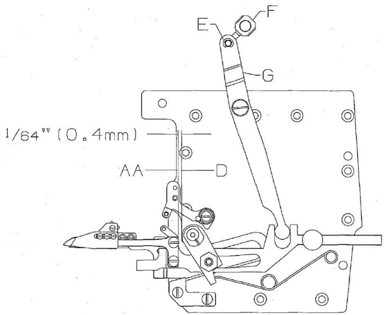
text_image
1/64" (0.4mm) AA D E F GUNDERBED THREAD TRIMMER ASSEMBLY Knife Adjustment
When positioning lower knife (G), eyelet (J) must be seated to the right.
Lower knife (G) must be seated to the right and all the way forward when tightened.
Loosen 2 screws (K).
Move eyelet (J) to the right as required.
Set lower knife as required.
Retighten screws (K).
To ensure no binds, extend knife (G) to the left and loosen upper knife screws (H) at the same time.
Retighten screws (H).

text_image
Knife Extended G H TORQUE: 14 in. lbs. (1.6Nm) To Touch Seated KUNDERBED THREAD TRIMMER ASSEMBLY
Upper knife (L) should overlap lower knife (G) by: .020" (0.5mm).
The distance from clamping leaf spring (N) to the tip of lower knife (G) should be: 1/8" (3mm). Clamping leaf spring (N) should be flush with knife at edge (BB).
NOTE: The clamping leaf spring must be set to only clamp the looper thread, NOT the needle threads.
The distance from tension leaf spring (M) to the back of upper knife (L, @ point CC) should be: .020" (0.5mm) to .040" (1.0mm).

text_image
.020" (0.5mm) CC L G
text_image
G BB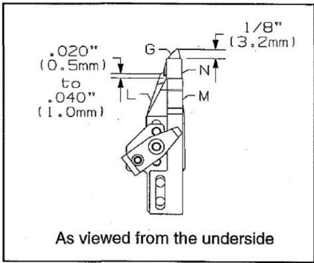
text_image
.020" (0.5mm) to .040" (1.0mm) G 1/8" (3.2mm) N L M As viewed from the undersideUPPER KNIFE AND CLAMPING SPRING
Loosen two screws (H) and screw (H1).
Move upper knife (L) and clamping leaf spring (N) as required.
Retighten screws (H) and (H1).
TENSION SPRING
Loosen two screws (P).
Adjust leaf spring (M) as required.
Retighten screws.

text_image
H1 P HUNDERBED THREAD TRIMMER ASSEMBLY
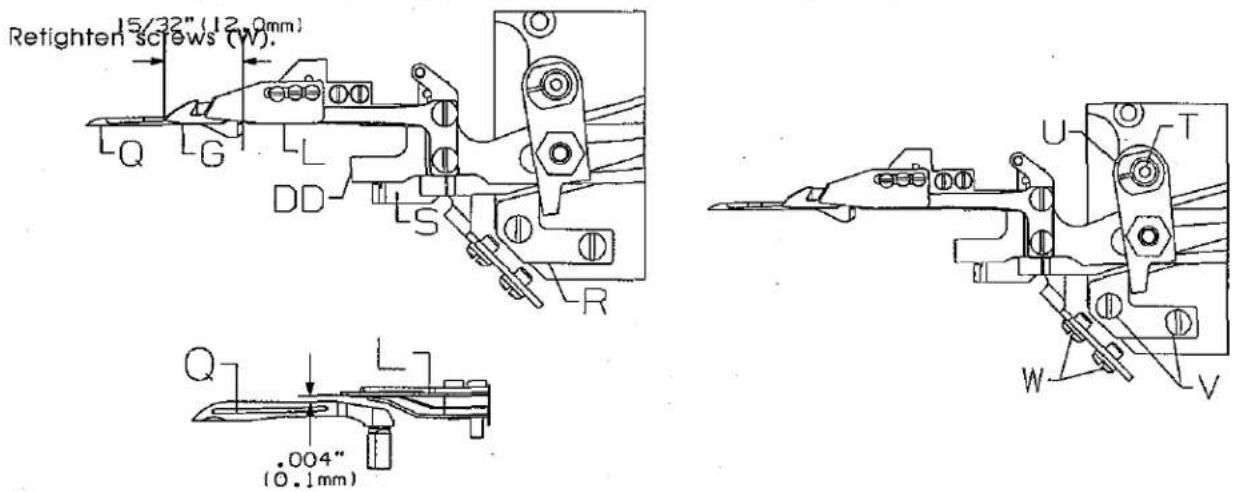
With the needles at top dead center: Lower knife (G) should be extended past the heel of looper (Q) by:
15/32" (12.0mm), for the following adjustments.
The tip of lower knife (G) should be centered front to back, to the rear edge of the flat on top of looper (Q).
Stop (R) sets the distance of the upper knife and springs to the looper, it should be centered in its slots.
Guide (S) should just contact edge (DD) of knife mechanism.
On cover stitch machines (G) should be set slightly rearword .005" (.10mm) of the standard adjustment.
The bottom of lower knife (L) should clear looper (Q) by .004" (0.1mm).
Move eccentric (U) as required.
Retighten screw (T).
STOP DISTANCE
Loosen screws (V).
Move stop (R) as required.
Retighten screws (V).
GUIDE DISTANCE
Loosen screws (W).
Move guide (S) as required to just contact edge (DD).
Retighten screws (W).
Loosen screws (W). Move guide (S) as required to obtain .004" (0.1mm) dimension.
text_image
Retighten screws (W). 15/32" (12.0mm) Q G L DD S R Q .004" (0.1mm) U T W VUNDERBED THREAD TRIMMER
ELECTROPNEUMATIC DRIVE
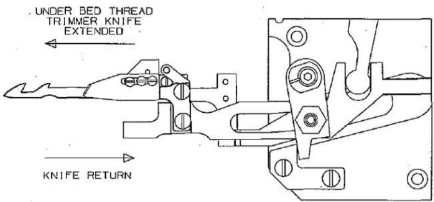
Adjust the metering screws so that thread trimmer mechanism and knife move smoothly left to right and the threads are cleanly cut and clamped.
text_image
. UNDER BED THREAD TRIMMER KNIFE EXTENDED KNIFE RETURNTo increase the speed of the knife return, turn screw (A) counterclockwise.
To decrease the speed of the knife, turn screw (A) clockwise.
To increase the speed of extending the knife, turn screw (B) counterclockwise.
To decrease the speed of extending the knife, turn screw (B) clockwise.

text_image
Technical diagram of a mechanical or electrical component with labeled parts A and B, showing internal components and connections.SETTING PROXIMITY SWITCH
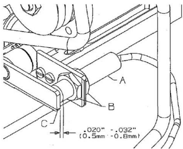
Proximity switch prevents motor from running when thread trimmer mechanism is not in extreme right position.
When moving thread trimmer mechanism 0.020" (0.5mm) to left LED must go out, motor will not start.
Move thread trimmer mechanism to its extreme right (end) position.
Switch on motor (do not run).
Loosen nuts (B).
Adjust switch (A) closer to lever (C) until LED illuminates.
Distance should be between 0.020 to 0.032" (0.5 to 0.8mm).
text_image
A B C .020" -.032" (0.5mm - 0.8mm)SOLENOID/PNEUMATIC THREAD WIPER
Bracket installed at 90 angle to needles.
Wiper hook (A) must deflect needle threads to operator on downstroke, (Fig. 1). Also the catch of the hook must pass the left needle by 1/8" (3.0mm).
On return, wiper hook must catch all needle threads (Fig. 2) and draw them into leaf spring (B) to be clamped.
Wiper hook (A) and leaf spring (B) should be flush at point (C) when at rest position.

text_image
Technical diagram of a mechanical clamp or bracket assembly with labeled parts A, B, and C
natural_image
Technical line drawing of a mechanical device with three vertical rods and a base mount (no text or symbols)FIG.1

text_image
1/8" (3.0mm)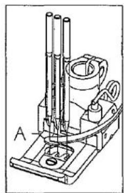
natural_image
Technical line drawing of a microscope with labeled component A (no text or symbols beyond label)FIG.2
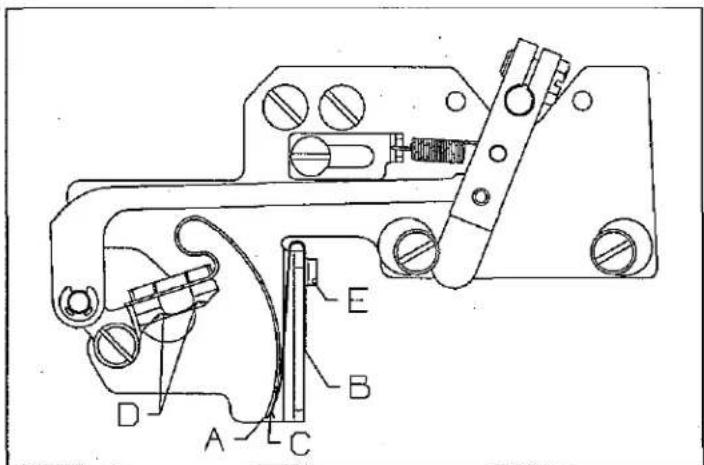
ADJUSTING THREAD WIPER
Disconnect power supply for thread wiper.
Loosen screws (D). Move wiper (A) left or right as necessary.
Retighten screws (D).
Operate wiper manually to check ajustment.
Loosen screw (E), move leaf spring (B) flush with wiper (A) at point (C).
Retighten screw (E).
Reconnect power supply.
text_image
Technical diagram of a mechanical device with labeled parts A, B, C, D, ETo lengthen travel past left needle.
Disconnect power supply to thread wiper.
Loosen stop screw (A) and rotate eccentric (B) so high lobe is further to left. Retighten stop screw (A).
To move wiper higher in leaf spring.
Loosen screw (C) and rotate eccentric (D) so high lobe is further to the right. Tighten stop screw (C).
Reconnect power supply.
NOTE: Recheck leaf spring setting to wiper.

text_image
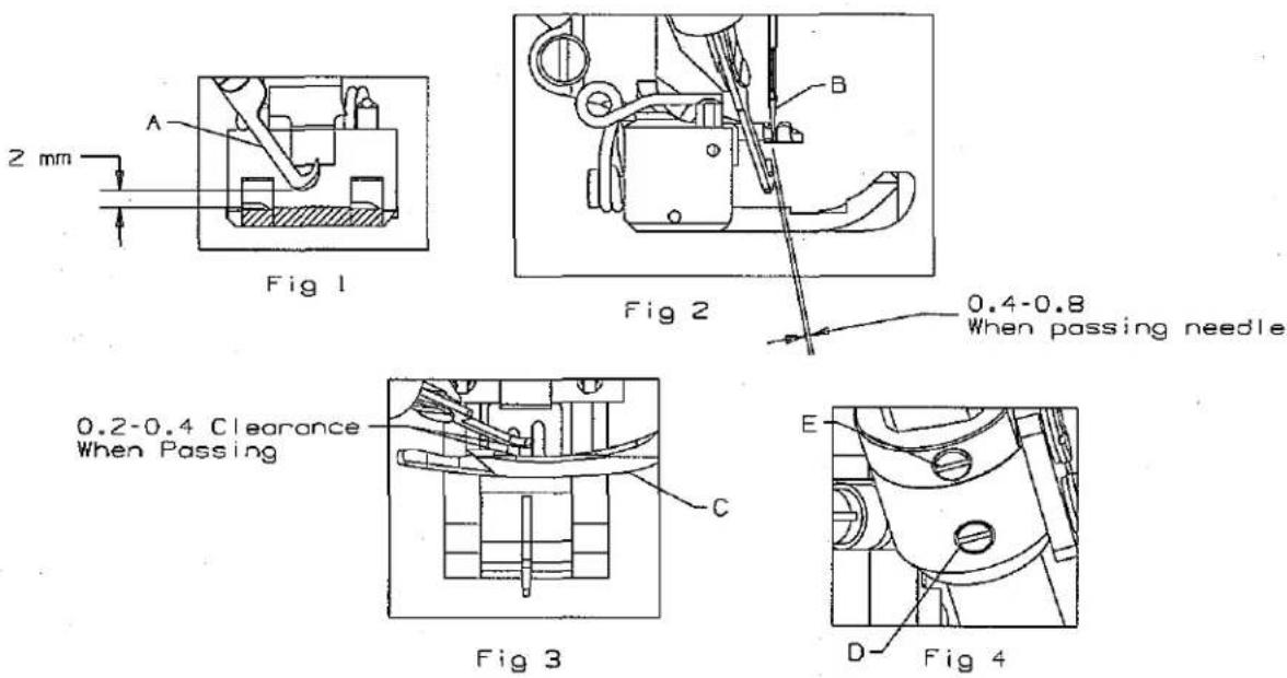
Technical diagram of a mechanical device with labeled components A, B, C, DPNEUMATIC/ELECTRIC COVER THREAD TRIMMER
The following adjustments are made with the needles at top dead center.
Set the pressure of knife (A, Fig. 1) to the minimum and still cut the spreader thread.
The trimmer activates so the hook of the knife (A, Fig. 1) picks up the spreader thread from the underside where the thread goes from the spreader to the switch.
The bottom of the moving knife should be 2mm above the presser foot when the moving knife is extended, (Fig. 1).
The clearance of the knife tip (A, Fig. 1) should be .4 to .8mm from the left needle (B, Fig. 2) and .2 to .4mm from the spreader (C, Fig. 3). the angle should be set to pick up the spreader thread.
Tighten the set screw (D, Fig. 4) in the assembly holder and also tighten the set screw (E, Fig. 4) in the collar with the collar against the holder.
The collar screw should not be removed once the trimmer is adjusted. The collar will hold the adjusted position of the trimmer if it should be removed from the holder.
NOTE: Adjust the presser foot delay so it does not interfere with the trimmer.
0.4-0.8
When passing needle
NEEDLE THREAD BLOWER ASSEMBLY
Needle threads must be blown out from under a raised presser foot after material has been removed.
AIR FLOW
- Turn needle valve (A) clockwise to decrease air flow.
- Turn needle valve (A) counterclockwise to increase air flow.

natural_image
Technical line drawing of a mechanical component with no visible text or symbols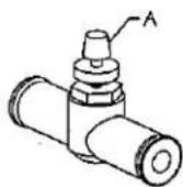
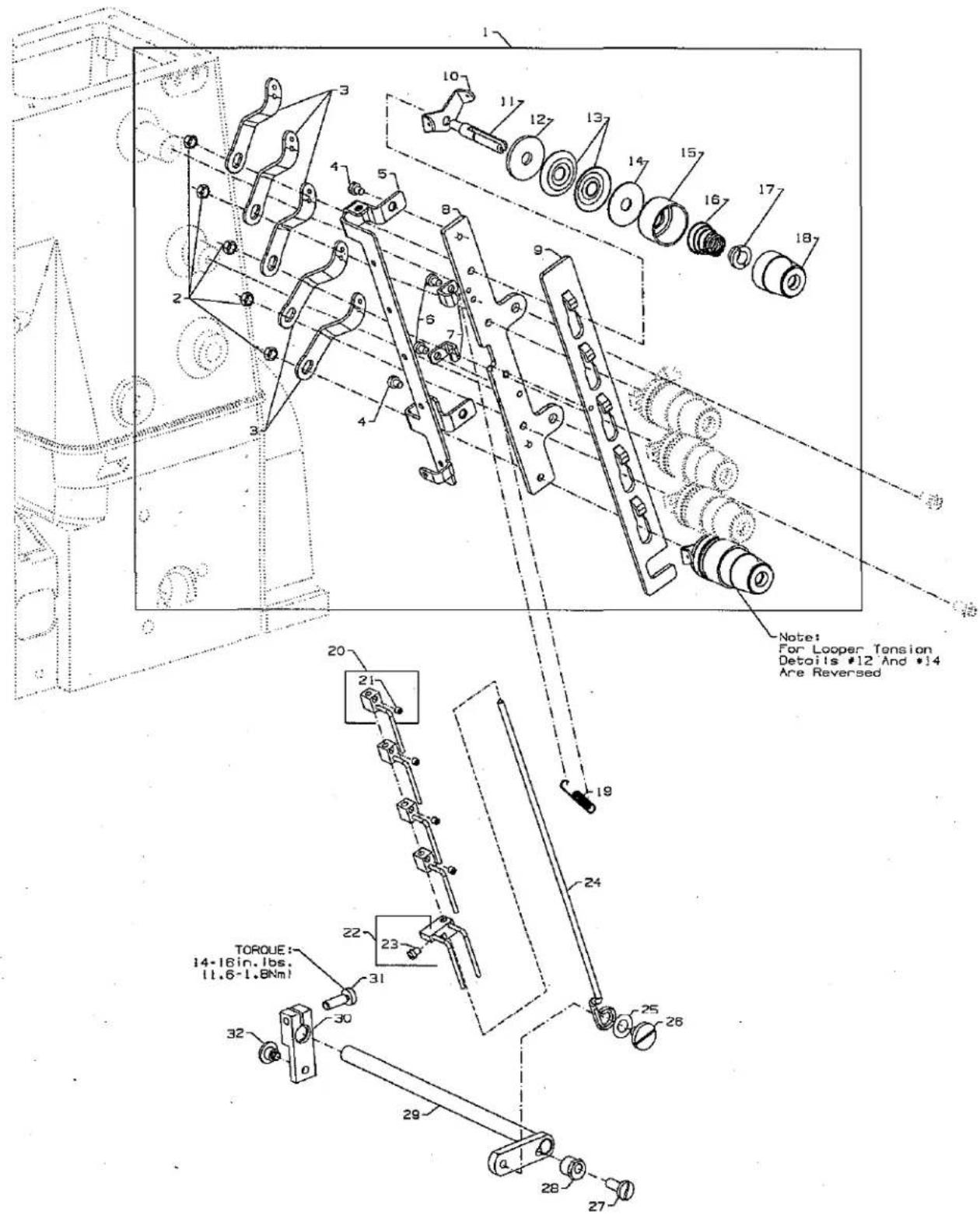
text_image
Note: For Looper Tension Details #12 And #14 Are Reversed TORQUE: 14-18 in. lbs. (11.6-1.BNm) 19 20 21 22 23 24 25 26 27 28 29 30 31 32 33 34 35 36 37 38 39 40 41 42 43 44 45 46 47 48 49 50 51 52 53 54 55 56 57 58 59 60 61 62 63 64 65 66 67 68 69 70 71 72 73 74 75 76 77 78 79 80 81 82 83 84 85 86 87THREAD TENSION
| Ref.No. | Juki Part No. | Description | Code | Amt.Req. |
| 1. | US-0029477-NL | 5 Thread Tension Assembly | 29477NL | 1 |
| 2. | NS-611420-SP | Nut | NS6110420SP | 5 |
| 3. | 300-46304 | Lead-in Thread Guide | 57865 | 5 |
| 4. | SS-7090520-SP | Screw | SS7090520SP | 2 |
| 5. | US-0050392-AU | Thread Guide | 50392AP | 1 |
| 6. | SS-7090520-SP | Screw | SS7090520SP | 2 |
| 7. | US-0050392-AV | Guide, for tension disc separator | 50392AV | 2 |
| 8. | US-0005039-2X | Tension Bracket | 50392X | 1 |
| 9. | US-0050392-AR | Tension Disc Separator | 50392AR | 1 |
| 10. | 300-46205 | Thread Tension Eyelet | 57892K | 5 |
| 11. | 303-63006 | Tension Post | 56392G | 5 |
| 12. | US-0666Z3-30 | Tension Disc Felt | 666-330 | 5 |
| 13. | B3126-012-000 | Tension Disc | B3126012000 | 10 |
| 14. | B3120-352-000 | Tension Disc Felt | B3120352000 | 5 |
| 15. | 303-62909 | Spring Shield | 56392H | 5 |
| 16. | B3103-804-000 | Spring, for spreader (blue) | B3103804000 | 1 |
| - | B3101-804-000 | Spring, for needle (red) | B3101804000 | 3 |
| - | B3121-804-000 | Spring, for looper (plain) | B3121804000 | 1 |
| 17. | B3112-704-000 | Ferrule, for tension spring | B3112704000 | 5 |
| 18. | 303-62800 | Knob, for spreader (blue) | 56392M | 1 |
| - | 303-62701 | Knob, for needle (red) | 56392L | 3 |
| - | US-0005039-2R | Knob, for looper (plain) | 50392R | 1 |
| 19. | 302-78303 | Extension Spring | 96711 | 1 |
| 20. | US-0005035-8Y | Thread Pull-off Hook | 50358Y | 4 |
| 21. | 300-83000 | Screw | 28C | 4 |
| 22. | 302-15800 | Thread Pull-off Hook | A9858 | 1 |
| 23. | 302-11106 | Screw | 77A | 1 |
| 24. | US-0050392-AS | Puller Rod, for thread puller | 50392AS | 1 |
| 25. | US-0005037-4A | Washer | 50374A | 1 |
| 26. | 302-78105 | Shoulder Screw | 99296 | 1 |
| 27. | 301-01109 | Screw | 22757 | 1 |
| 28. | 302-77800 | Tension Release Eccentric | G51346KA | 1 |
| 29. | US-0050392-AN | Tension Release Assembly | 50392AN | 1 |
| 30. | 302-77909 | Tension Release Lever | 99620 | 1 |
| 31. | 301-05803 | Screw | 22596 | 1 |
| 32. | 301-60808 | Screw | 22735 | 1 |
| UT COMPONENT DEVICE KEY | |
| UT DEVICE | COMPONENT USEDON DEVICE |
| UT1 | ● |
| UT2 | ● |
| UT3 | ● |
| UT4 | ● |
| UT5 | ● |
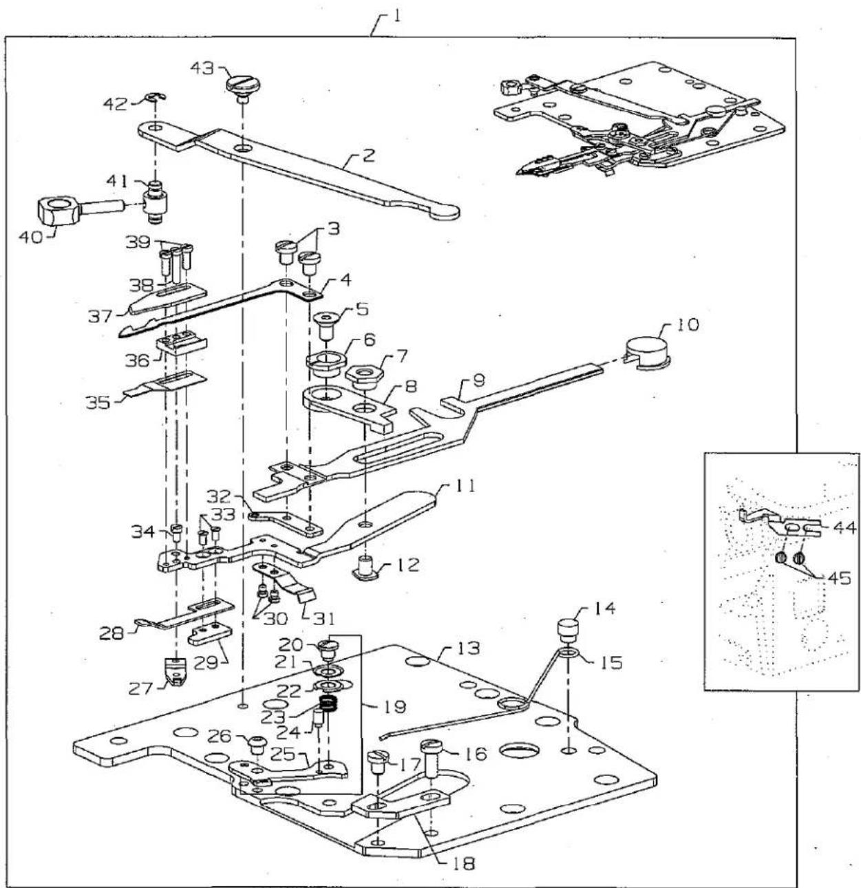
text_image
Technical diagram of a mechanical assembly with numbered components and an inset close-up viewUNDERBED THREAD TRIMMER ASSEMBLY
| Ref.No. | Juki Part No. | Description | Code | Amt.Req. |
| 1. | US-029480A-YH | Underbed Thread Trimmer Assembly | 29480AYH | 1 |
| 2. | 303-64608 | Lever | 34763P | 1 |
| 3. | 303-65308 | Screw | 18-1453 | 2 |
| 4. | 305-00300 | Lower Knife | 34749P | 1 |
| 5. | 303-64905 | Screw | 18-1450 | 1 |
| 6. | 303-64806 | Eccentric Guide | 34768A | 1 |
| 7. | US-0003476-8C | Guide Washer | 34768C | 1 |
| 8. | 303-64509 | Lever | 34750R | 1 |
| 9. | 301-54405 | Lower Knife Holder | 34750T | 1 |
| 10. | 303-64005 | Guide | 34750U | 1 |
| 11. | US-0034750-SA | Upper Knife Holder | 34750SA | 1 |
| 12. | US-0018Z14-72 | Screw | 18-1472 | 1 |
| 13. | 303-64103 | Oil Reserve Cover | 34382AC | 1 |
| 14. | 303-63808 | Pin | 34751MS | 1 |
| 15. | US-0050332-AD | SprinG | 50332AD | 1 |
| 16. | 302-18309 | Screw | 22585 | 1 |
| 17. | 303-67007 | Screw | 18-1449 | 2 |
| 18. | US-0050337-AX | Stop | 50337AX | 1 |
| 19. | US-029480A-YJ | Looper Thread Nipper Assembly | 29480AYJ | 1 |
| 20. | US-0050357-AW | Nipper Plate Screw | 50357AW | 1 |
| 21. | US-0050357-AX | Nipper Plate | 50357AX | 1 |
| 22. | US-0050357-AT | Nipper Plate | 50357AT | 1 |
| 23. | US-0050357-AU | Nipper Spring | 50357AU | 1 |
| 24. | US-0050357-AV | Nipper Guard Post | 50357AV | 1 |
| 25. | US-0005036-6L | Nipper Plate Eyelet | 50366L | 1 |
| 26. | 303-91502 | Screw | 18C1471 | 1 |
| 27. | 303-66207 | Tension Lever | 34751MT | 1 |
| 28. | 303-66108 | Leaf Spring | 34773D | 1 |
| 29. | 303-66306 | Threaded Plate | 34769B | 1 |
| 30. | SM-6020250-TP | Screw | SM6020250TP | 2 |
| 31. | 303-66009 | Leaf Spring | 34773E | 1 |
| 32. | US-0050368-AE | Looper Thread Pull-off Eyelet | 50368AE | 1 |
| 33. | SM-1020450-TP | Screw | SM1020450TP | 2 |
| 34. | 304-91005 | Screw | 18-1473 | 1 |
| 35. | 303-65704 | Leaf Spring | 34773F | 1 |
| 36. | 303-65605 | Lower Knife Guide | 34750P | 1 |
| 37. | 303-65407 | Upper Knife | 34770M | 1 |
| 38. | US-0018Z14-74 | Screw | 18-1474 | 1 |
| 39. | SM-6020600-TP | Screw | SM6020600TP | 2 |
| 40. | 303-65209 | Driving Link | 34752M | 1 |
| 41. | 303-65100 | Carrier Bolt | 34752N | 1 |
| 42. | RE-0250000-KO | E-Ring | RE025000KO | 1 |
| 43. | SD-0600176-SP | Screw | SD0600176SP | 1 |
| 44. | 303-86502 | Guide | 34794A | 1 |
| 45. | 300-90500 | Screw, for guide | 90 | 2 |
| UT COMPONENT DEVICE KEY | |
| UT DEVICE | COMPONENT USED ON DEVICE |
| UT1 | ● |
| UT2 | ● |
| UT3 | ● |
| UT4 | ● |
| UT5 | ● |
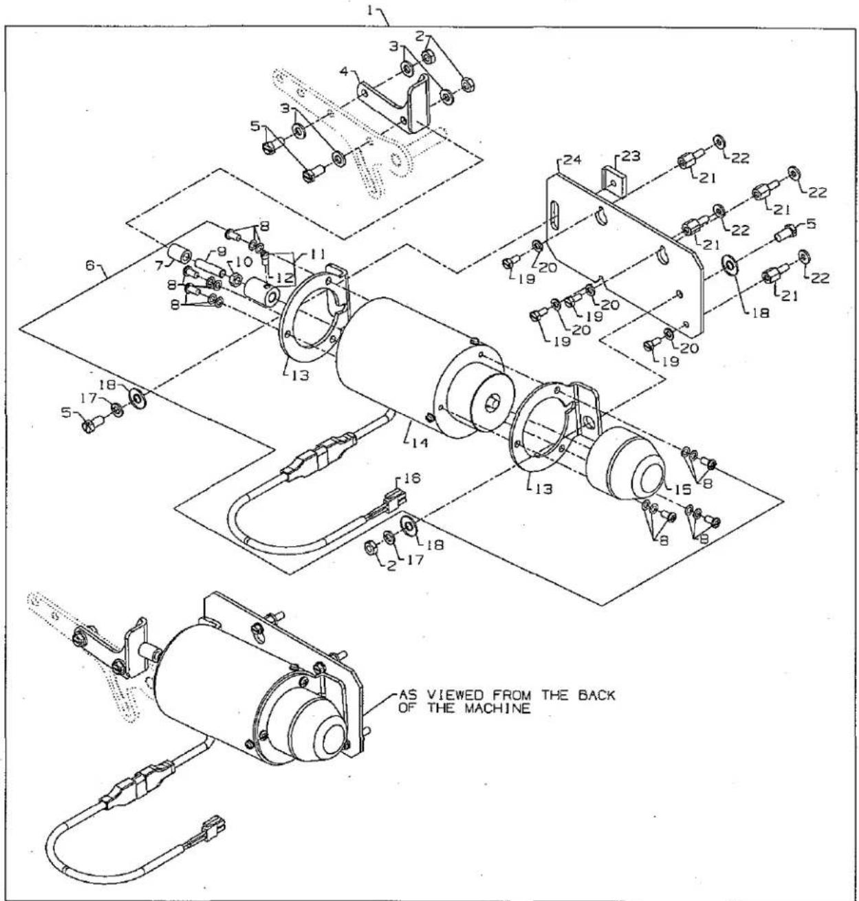
text_image
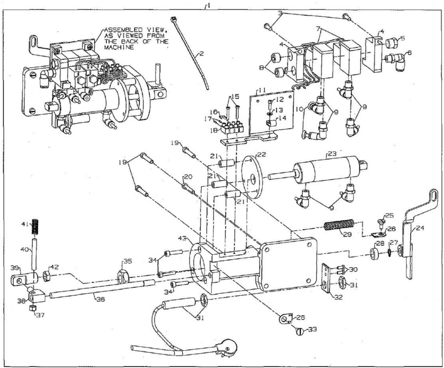
AS VIEWED FROM THE BACK OF THE MACHINEELECTRIC PRESSER FOOT LIFTER ASSEMBLY
| Ref.No. | Juki Part No. | Description | Code | Amt.Req. |
| 1. | US-0002992-0D | Electric Drive Assembly | 29920D | 1 |
| 2. | NS-6150430-SP | Nut | NS6150430SP | 3 |
| 3. | 301-78602 | Washer | 95951 | 4 |
| 4. | US-0005036-7H | Lifter | 50367H | 1 |
| 5. | SS-9151420-TP | Hex Screw | SS9151420TP | 4 |
| 6. | US-000670K-82 | Solenoid Assembly | 670K82 | 1 |
| 7. | 304-96905 | Cap | 92855A | 1 |
| 8. | SS-4051281-SE | Screw | SS4051281SE | 6 |
| 9. | US-0005039-5N | Stud | 50395N | 1 |
| 10. | NS-6660430-SP | Nut | NS6660430SP | 1 |
| 11. | US-0005033-3B | Coupling | 50333B | 1 |
| 12. | SS-6110710-TP | Screw | SS6110710TP | 1 |
| 13. | GAK-33034000 | Bracket | GAK33034000 | 2 |
| 14. | GAK-8403000A | Solenoid | GAK8403000A | 1 |
| 15. | GAK-3303600A | Cap | GAK3303600A | 1 |
| 16. | US-0670E14-03 | Adapter Cable | 670E1403 | 2 |
| 17. | WS-0631510-KP | Lock Washer | WS0631510KP | 3 |
| 18. | 300-95905 | Washer | 53636C | 4 |
| 19. | SS-9111010-SP | Hex Screw | SS9111010SP | 4 |
| 20. | WS-0510002-KP | Lock Washer | WS0510002KP | 4 |
| 21. | US-0005039-5P | Stand-Off | 50395P | 4 |
| 22. | 300-98107 | Washer | 35032H | 1 |
| 23. | US-0005039-5R | Clamp Plate | 50395R | 1 |
| 24. | US-0005038-3S | Base Plate | 50383S | 1 |
| UT COMPONENT DEVICE KEY | |
| UT DEVICE | COMPONENT USEDON DEVICE |
| UT1 | ● |
| UT2 | ● |
| UT3 | |
| UT4 | |
| UT5 | |

text_image
Technical diagram of a mechanical assembly with numbered components for identification1
ELECTRIC THREAD WIPER ASSEMBLY
| Ref.No. | Juki Part No. | Description | Code | Amt.Req. |
| 1. | US-0002990-6M | Electric Thread Drive Assembly | 29906M | 1 |
| 2. | 301-54603 | Retaining Ring | 96280 | 2 |
| 3. | US-0099591-DP | Pin | 99591DN | 1 |
| 4. | US-0009954-5G | Push Rod | 99545G | 1 |
| 5. | PH-0300083-UO | Pin | PH0300083UO | 1 |
| 6. | US-0009964-6J | Lever | 99646J | 1 |
| 7. | SS-9120910-TP | Screw | SS9120910TP | 1 |
| 8. | SS-4091015-SP | Screw | SS4091015SP | 2 |
| 9. | 301-54504 | Stop Eccentric | 50363BF | 2 |
| 10. | 305-43201 | Wiper Bracket | 99650E | 1 |
| 11. | 300-52104 | Electric Solenoid Rotary | 670K15 | 1 |
| 12. | US-0009954-5H | Nut Plate | 99545H | 1 |
| 13. | SS-6060210-SP | Screw | SS6060210SP | 1 |
| 14. | 302-26906 | Washer | 96150 | 1 |
| 15. | 301-57408 | Leaf Spring | 99697AA | 1 |
| 16. | SS-7090610-SP | Screw | SS7090610SP | 2 |
| 17. | 302-43901 | Hex Nut | 51250C | 1 |
| 18. | SS-6060510-TP | Screw | SS6060510TP | 2 |
| 19. | US-0005036-2B | Plate | 50362B | 1 |
| 20. | 304-40200 | Wiper Hook | 99653B | 1 |
| 21. | US-0009965-7E | Lever | 99657E | 1 |
| 22. | 301-54603 | Washer | 96161 | 1 |
| 23. | 302-69203 | Shoulder Screw | 99358 | 1 |
| 24. | SS-7090510-SP | Screw | SS7090510SP | 1 |
| 25. | US-0099591-DP | Bracket | 99591DP | 1 |
| 26. | US-0050332-AB | Extension Spring | 50332AB | 1 |
| UT COMPONENT DEVICE KEY | |
| UT DEVICE | COMPONENT USED ON DEVICE |
| UT1 | ● |
| UT2 | |
| UT3 | |
| UT4 | |
| UT5 | |

text_image
ASSEMBLED VIEW, AS VIEWED FROM BACK OF THE MACHINE.ELECTRIC DRIVE DOUBLE ACTION ASSEMBLY
| Ref.No. | Jukl Part No. | Description | Code | Amt.Req. |
| 1. | US-000670K-28 | Electric Drive Assembly | 670K28 | 1 |
| 2. | 302-93609 | Screw | 95169 | 1 |
| 3. | US-067E150-8 | Cable Clamp | 670E1508 | 1 |
| 4. | 301-60600 | Solenoid | 998-306B | 1 |
| 5. | 303-01105 | Bushing | 99617A | 3 |
| 6. | 301-56400 | Hose Clamp | 998-358E | 2 |
| 7. | SS-6111010-SP | Screw | SS6111010SP | 1 |
| 8. | 301-56608 | Screw | 95179K | 2 |
| 9. | 301-57200 | Wire | 1318001 | 1 |
| 10. | US-0670E13-02 | Terminal Block | 670E1302 | 1 |
| 11. | 301-56905 | Cable End Plate | 998-297A | 2 |
| 12. | 301-55600 | Screw | 22852A | 3 |
| 13. | 302-16709 | Screw | 22517A | 1 |
| 14. | 303-00404 | Mounting Bracket | G52882KW | 1 |
| 15. | 303-01204 | Screw | 95177 | 3 |
| 16. | 301-64107 | Spring | 51292F2 | 1 |
| 17. | 303-01006 | Clamping Screw | 99619 | 1 |
| 18. | 303-01303 | Driving Connection | 99616 | 1 |
| 19. | 301-60501 | Nut | 95251 | 1 |
| 20. | 302-43109 | Nut | 55235E | 1 |
| 21. | 303-01402 | Cross Head | 99614D | 1 |
| 22. | 301-56004 | Shaft | 99613D | 1 |
| 23. | US-00670E8-15 | Switch Assembly | 670E815 | 1 |
| 24. | 303-00107 | Spring Eyelet | 80696RA | 1 |
| 25. | 302-16006 | Screw | 14076 | 1 |
| 26. | 303-00701 | Bracket | 34762 | 1 |
| 27. | 302-18309 | Screw | 22585 | 2 |
| 28. | 303-00503 | Washer | 99615 | 1 |
| 29. | 301-55501 | Retaining Ring | 96261 | 1 |
| 30. | US-0050373-DG | Lever | 50373DG | 1 |
| 31. | 301-03600 | Screw | 22569B | 1 |
| 32. | 303-00107 | Spring Eyelet | 80696RA | 1 |
| 33. | 303-00206 | Spring | 96721 | 1 |
| UT COMPONENT DEVICE KEY | |
| UT DEVICE | COMPONENT USED ON DEVICE |
| UT1 | ● |
| UT2 | ● |
| UT3 | |
| UT4 | |
| UT5 | |
text_image
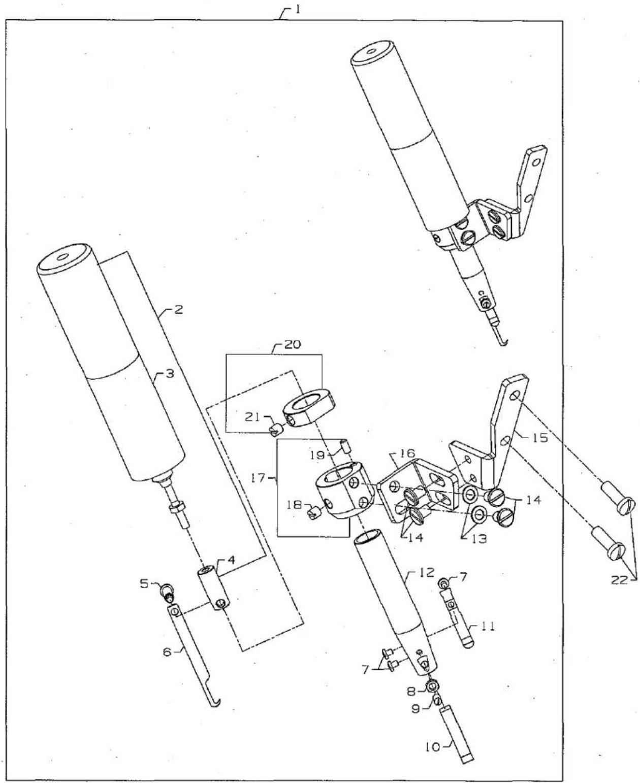
Technical diagram of mechanical assembly with numbered components and labeled partsELECTRIC SPREADER THREAD TRIMMER ASSEMBLY
| Ref.No. | Juki Part No. | Description | Code | Amt.Req. |
| 1. | US-0029980-LE | Spreader Thread Trimmer Assembly, Electric | 29980LE | 1 |
| 2. | US-0029105-BR | Knife Holder Assembly | 29105BR | 1 |
| 3. | US-000670K-85 | Solenold | 670K85 | 1 |
| 4. | US-0005037-2D | Moving Knife Holder | 50372D | 1 |
| 5. | 305-43904 | Screw | 22731 | 1 |
| 6. | US-0005037-OH | Moving Knife | 50370H | 1 |
| 7. | SS-706310-SP | Screw | SS706310SP | 2 |
| 8. | NS-6080210-SP | Nut | NS6080210SP | 1 |
| 9. | SS-8080610-SP | Screw | SS8080610SP | 1 |
| 10. | US-0005034-9F | Lower Knife | 50349F | 1 |
| 11. | US-0050332-AG | Spring | 50332AG | 1 |
| 12. | US-0005037-2C | Knife Holder | 50372C | 1 |
| 13. | WP-0450846-SP | Washer | WP0450846SP | 2 |
| 14. | SS-6110610-TP | Screw | SS6110610TP | 4 |
| 15. | US-0050383-AT | Bracket | 50383AT | 1 |
| 16. | US-0050383-AS | Bracket | 50383AS | 1 |
| 17. | US-0005033-3L | Collar Guide | 50333L | 1 |
| 18. | SS-8110520-TP | Screw | SS8110520TP | 1 |
| 19. | PH-0300062-CO | Pin | PH0300062CO | 1 |
| 20. | US-0005033-3K | Collar | 50333K | 1 |
| 21. | SS-8110520-TP | Screw | SS8110520TP | 1 |
| 22. | SS-4121915-SP | Mounting Screws | SS4121915SP | 2 |
| UT COMPONENT DEVICE KEY | |
| UT DEVICE | COMPONENT USED ON DEVICE |
| UT1 | |
| UT2 | ● |
| UT3 | |
| UT4 | |
| UT5 | |

text_image
To: 29921C Pneumatic Presser Foot Lifter Assembly To: B To: 29480ATW pneumatic drive assembly 1 2 3 4 5 6 TO: air supplyPNEUMATIC CONTROL
| Ref.No. | Jukl Part No. | Description | Code | Amt.Req. |
| 1. | US-029480A-XA | Pneumatic Control Kit | 29480AXA | 1 |
| 2. | 300-66401 | Wood Screw | 90561K | 2 |
| 3. | US-0099683-CP | Mounting Bracket | 99683CP | 1 |
| 4. | US-000671D-42 | Filter/ Regulator Assembly | 671D42 | 1 |
| 5. | US-000671F2-41 | Barb Fitting | 671F241 | 1 |
| 6. | 301-79402 | Elbow Fitting - 6mm x 1/2" NPT | 671F81A | 1 |
| - | 304-21309 | Air Tubing - 6mm O.D. x 1m (not shown) | 671B182 | 1 |
| 7. | US-029480A-WU | Presser Foot Lifter Kit | 29480AWU | 1 |
| 8. | 301-52102 | Elbow Fitting - 6mm x 1/8" NPT | 671F81C | 2 |
| 9. | 301-52508 | Screw - 4mm | 95415 | 2 |
| 10. | 301-66508 | Muffler | 660-403 | 1 |
| 11. | 301-55105 | Valve | 671-50 | 1 |
| 12. | 301-52201 | Splitter | 671F86B | 1 |
| - | 305-3300 | Cable Harness (not shown) | 670E673 | 1 |
| - | 305-43409 | Connector (male, not shown) | RM2724A | 2 |
| - | 305-43508 | Air Tubing - 6mm O.D. x 1mm (not shown) | 671B23 | 1 |
| UT COMPONENT DEVICE KEY | |
| UT DEVICE | COMPONENT USED ON DEVICE |
| UT1 | |
| UT2 | |
| UT3 | ● |
| UT4 | |
| UT5 | ● |
text_image
ASSEMBLED VIEW, AS VIEWED FROM THE BACK OF THE MACHINE 41 40 39 38 37 36 35 34 33 32 31 30 29 28 27 26 25 24 23 22 21 20 19 18 17 16 15 14 13 12 11 10 9 8 7 6 5 4 3PNEUMATIC DRIVE DOUBLE ACTION ASSEMBLY
| Ref.No. | Juki Part No. | Description | Code | Amt.Req. |
| 1. | US-029480A-TW | Pneumatic Drive Assembly | 29480ATW | 1 |
| 2. | 300-66906 | Cable Tie | RM2871B | 2 |
| 3. | SS-4121415-SP | Screw | SS4121415SP | 2 |
| 4. | 301-79600 | Manifold | 671-104A | 1 |
| 5. | 301-79501 | Silencer | 660-763 | 1 |
| 6. | 301-79402 | Elbow | 671F81A | 1 |
| 7. | 301-79709 | Mac Valve | 671-103B | 2 |
| 8. | 301-79808 | Plug | 671F87 | 2 |
| 9. | 301-52300 | Elbow | 671F82C | 6 |
| 10. | 301-80004 | Plug | 670G276 | 2 |
| 11. | US-0005038-3N | Bracket | 50383N | 1 |
| 12. | 300-88603 | Screw | 22729 | 1 |
| 13. | 302-96800 | Washer | 95954 | 1 |
| 14. | 301-56400 | Cable Clamp | 998-358E | 1 |
| 15. | 305-43607 | Screw | 22894AX | 2 |
| 16. | 301-57200 | Wire | 1318001 | 1 |
| 17. | 301-56905 | Cable End Sleeve | 998-297A | 2 |
| 18. | US-0670E13-02 | Terminal | 670E1302 | 1 |
| 19. | 301-55600 | Screw | 22852A | 3 |
| 20. | 302-16709 | Screw | 22517A | 1 |
| 21. | 301-56202 | Spacer | 99617T | 3 |
| 22. | 301-56301 | Disc | 99591DH | 1 |
| 23. | 305-43706 | Air Cylinder | 99694A | 1 |
| 24. | US-0050373-DG | Lever | 50373DG | 1 |
| 25. | 301-03600 | Screw | 22569B | 1 |
| 26. | 303-00107 | Spring Eyelet | 80696RA | 1 |
| 27. | 301-55501 | Retaining Ring | 96261 | 1 |
| 28. | 303-00503 | Washer | 99615 | 1 |
| 29. | 303-00206 | Spring | 96721 | 1 |
| 30. | 302-18309 | Screw | 22585 | 2 |
| 31. | US-00670E8-15 | Switch Assembly | 670E815 | 1 |
| 32. | 303-00701 | Bracket | 34762 | 1 |
| 33. | 302-16006 | Stud | 14076 | 1 |
| 34. | 301-55006 | Screw | 95411 | 3 |
| 35. | 301-56707 | Nut | 99327 | 1 |
| 36. | 301-56004 | Shaft | 99613D | 1 |
| 37. | 302-43109 | Nut | 55235E | 1 |
| 38. | 303-01402 | Cross Head | 99614D | 1 |
| 39. | 301-55907 | Connector | 99616A | 1 |
| 40. | 303-01006 | Clamping | 99619 | 1 |
| 41. | 302-43208 | Spring | 51292F2 | 1 |
| 42. | 301-55808 | Nut | 21233FB | 1 |
| 43. | 303-00404 | Support Bracket | G52882KW | 1 |
| 304-21309 | Tubing (not shown) | 671B182 | 2ft. | |
| 305-43805 | Nylon Black Tubing (not shown) | 6-878 | 1 | |
| 301-56400 | Hose Clamp (not shown) | 998-358E | 1 |
| UT COMPONENT DEVICE KEY | |
| UT DEVICE | COMPONENT USED ON DEVICE |
| UT1 | |
| UT2 | |
| UT3 | ● |
| UT4 | ● |
| UT5 | ● |

text_image
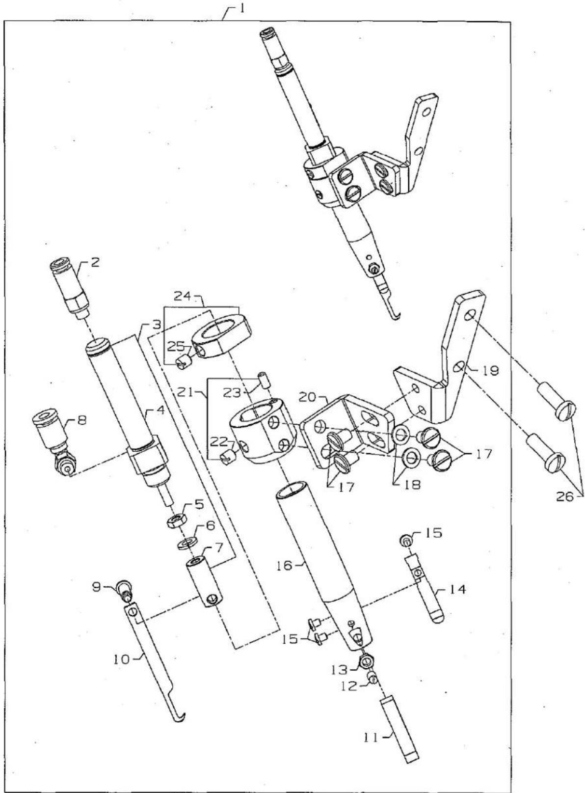
Technical diagram of a mechanical assembly with numbered components for identification and assembly reference.PNEUMATIC THREAD WIPER ASSEMBLY
| Ref.No. | Juki Part No. | Description | Code | Amt.Req. |
| 1. | US-0002990-6L | Pneumatic Thread Wiper Assembly | 29906L | 1 |
| 2. | 301-64206 | Screw | 95167CV | 2 |
| 3. | 301-64305 | Clevis | 35086BK | 1 |
| 4. | 301-64404 | Hex Nut | 95294 | 1 |
| 5. | 301-64503 | Pneumatic Cylinder | 999-191H | 1 |
| 6. | 301-52003 | Pneumatic Fitting | 999-411M5-4 | 2 |
| 7. | PH-0300083-U0 | Pin | PH0300083U0 | 1 |
| 8. | 302-71209 | Hex Nut | 95259 | 2 |
| 9. | 302-67801 | Washer | 95956 | 2 |
| 10. | US-0009965-0D | Wiper Bracket | 99650D | 1 |
| 11. | SS-4091015-SP | Screw | SS4091015SP | 2 |
| 12. | 301-54504 | Stop Eccentric | 50363BF | 2 |
| 13. | SS-6080610-TP | Screw | SS6080610TP | 2 |
| 14. | US-0009954-5H | Nut Plate | 99545H | 1 |
| 15. | US-0005233-6B | Pin | 52336B | 1 |
| 16. | US-0009954-5F | Plate | 99545F | 1 |
| 17. | 301-54702 | Retaining Ring | 96280 | 3 |
| 18. | SS-6060210-SP | Screw | SS6060210SP | 1 |
| 19. | 302-26906 | Washer | 96150 | 1 |
| 20. | 301-57408 | Leaf Spring | 99697AA | 1 |
| 21. | SS-7090610-SP | Screw | SS7090610SP | 2 |
| 22. | 302-43901 | Hex Nut | 51250C | 1 |
| 23. | 302-39909 | Washer | 99652A | 2 |
| 24. | US-0005036-2B | Plate | 50362B | 1 |
| 25. | US-0009965-3C | Wiper Hook | 99653B | 1 |
| 26. | US-0009965-7E | Lever | 99657E | 1 |
| 27. | SS-6060510-TP | Screw | SS6060510TP | 2 |
| 28. | 301-54603 | Washer | 96161 | 1 |
| 29. | 302-69203 | Shoulder Screw | 99358 | 1 |
| 30. | US-0099591-DN | Pin | 99591DN | 1 |
| 31. | US-0009954-5G | Push Rod | 99545G | 1 |
| 32. | 301-64800 | Roller | 35086BJ | 1 |
| 33. | US-0009964-6J | Lever | 99646J | 1 |
| 34. | SS-9120910-TP | Screw | SS9120910TP | 1 |
| UT COMPONENT DEVICE KEY | |
| UT DEVICE | COMPONENT USED ON DEVICE |
| UT1 | |
| UT2 | |
| UT3 | ● |
| UT4 | |
| UT5 | |

text_image
Technical diagram of a mechanical assembly with numbered components, likely a valve or pump mechanism.PRESSER FOOT LIFTER
| Ref.No. | Juki Part No. | Description | Code | Amt.Req. |
| 1. | SS-6122030-SP | Screw | SS6122030SP | 1 |
| 2. | US-0050383-AR | Cylinder Support Bracket | 50383AR | 1 |
| 3. | NS-6120310-SP | Nut | NS6120310SP | 1 |
| 4. | WS-0510002-KP | Washer | WS0510002KP | 1 |
| 5. | SS-4121015-SP | Screw | SS4121015SP | 1 |
| 6. | US-0005037-4K | Spacer | 50374K | 1 |
| 7. | US-029480A-XJ | Presser Foot Lifter Assembly | 29480AXJ | 1 |
| 8. | US-00671A3-60 | Air Cylinder | 671A360 | 1 |
| 9. | 301-52102 | Fitting | 671F81C | 1 |
| 10. | US-0050383-AF | Bracket | 50383AF | 1 |
| 11. | US-0660Z10-99 | Air Cylinder Cap | 660-1099 | 1 |
| 12. | SS-4121215-SP | Screw | SS4121215SP | 2 |
| UT COMPONENT DEVICE KEY | |
| UT DEVICE | COMPONENT USED ON DEVICE |
| UT1 | |
| UT2 | |
| UT3 | ● |
| UT4 | ● |
| UT5 | ● |
text_image
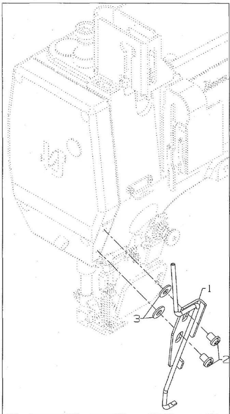
Technical diagram of a mechanical assembly with labeled components and dotted-line annotationsNEEDLE THREAD BLOWER ASSEMBLY
| Ref.No. | Juki Part No. | Description | Code | Amt.Req. |
| 1. | US-0050394-AJ | Needle Thread Blower Assembly | 50394AJ | 1 |
| 2. | SS-4120615-SP | Screw, for needle thread blower assembly | SS4120615SP | 2 |
| 3. | 302-87700 | Washer | 69H | 2 |
| UT COMPONENT DEVICE KEY | |
| UT DEVICE | COMPONENT USEDON DEVICE |
| UT1 | |
| UT2 | |
| UT3 | |
| UT4 | ● |
| UT5 | |
text_image
Technical diagram of mechanical assembly with numbered components for identificationPNEUMATIC SPREADER THREAD TRIMMER ASSEMBLY
| Ref.No. | Juki Part No. | Description | Code | Amt.Req. |
| 1. | US-0029480-LD | Pneumatic Spreader Thread Trimmer Assembly | 29980LD | 1 |
| 2. | US-00671F8-2G | Male Connector | 671F82G | 1 |
| 3. | US-0029105-BP | Knife Holder Assembly | 29105BP | 1 |
| 4. | US-00671A3-63 | Air Cylinder | 671A363 | 1 |
| 5. | US-0660Z11-05 | Nut | 660-1105 | 1 |
| 6. | WS-0410002-KP | Washer | WS0410002KP | 1 |
| 7. | US-0005037-2D | Moving Knife Holder | 50372D | 1 |
| 8. | US-00671F8-2F | Male Elbow | 671F82F | 1 |
| 9. | 305-43904 | Screw | 22731 | 1 |
| 10. | US-0005037-OH | Moving Knife | 50370H | 1 |
| 11. | US-0005034-9F | Lower Knife | 50349F | 1 |
| 12. | SS-8080610-SP | Screw | SS8080610SP | 1 |
| 13. | NS-6080210-SP | Nut | NS6080210SP | 1 |
| 14. | US-0050332-AG | Spring | 50332AG | 1 |
| 15. | SS-7060310-SP | Screw | SS7060310SP | 3 |
| 16. | US-0005037-2C | Knife Holder | 50372C | 1 |
| 17. | SS-6110610-TP | Screw | SS6110610TP | 4 |
| 18. | WP-0450846-SP | Washer | WP0450846SP | 2 |
| 19. | US-0050383-AT | Bracket | 50383AT | 1 |
| 20. | US-0050383-AS | Bracket | 50383AS | 1 |
| 21. | US-0005033-3L | Collagr. guide | 50333L | 1 |
| 22. | SS-8110520-TP | Screw | SS8110520TP | 1 |
| 23. | PH-0300062-CO | Pin | PH0300062C0 | 1 |
| 24. | US-0005033-3K | Collar | 50333K | 1 |
| 25. | SS-8110520-TP | Screw | SS8110520TP | 1 |
| 26. | SS-4120915-SP | Mounting Screws | SS4120915SP | 2 |
| UT COMPONENT DEVICE KEY | |
| UT DEVICE | COMPONENT USED ON DEVICE |
| UT1 | |
| UT2 | |
| UT3 | |
| UT4 | |
| UT5 | ● |
NUMERICAL INDEX OF PARTS
| Part No. | Page No. | Part No. | Page No. | Part No. | Page No. | Part No. | Page No. |
| 300-46205 | 17 | 302-16709 | 25, 31 | 305-43201 | 23 | US-0005033-3B | 21 |
| 300-46304 | 17 | 302-18309 | 19, 25, 31 | 305-43409 | 29 | US-0005033-3K | 27, 39 |
| 300-52104 | 23 | 302-26906 | 23, 33 | 305-43508 | 29 | US-0005033-3L | 27, 39 |
| 300-66401 | 29 | 302-39909 | 33 | 305-43607 | 31 | US-0005034-9F | 27, 39 |
| 300-66906 | 31 | 302-43109 | 25, 31 | 305-43706 | 31 | US-0005035-8Y | 17 |
| 300-83000 | 17 | 302-43208 | 31 | 305-43904 | 27, 39 | US-0005036-2B | 23, 33 |
| 300-88603 | 31 | 302-43901 | 23, 33 | B3101-804-000 | 17 | US-0005036-6L | 19 |
| 300-90500 | 19 | 302-67801 | 33 | B3103-804-000 | 17 | US-0005036-7H | 21 |
| 300-95905 | 21 | 302-69203 | 23, 33 | B3112-704-000 | 17 | US-0005037-0H | 27, 39 |
| 300-98107 | 21 | 302-71209 | 33 | B3120-352-000 | 17 | US-0005037-2C | 27, 39 |
| 301-01109 | 17 | 302-77800 | 17 | B3121-804-000 | 17 | US-0005037-2D | 27, 39 |
| 301-03600 | 25, 31 | 302-77909 | 17 | B3126-012-000 | 17 | US-0005037-4A | 17 |
| 301-05803 | 17 | 302-78105 | 17 | GAK-33034000 | 21 | US-0005037-4K | 35 |
| 301-52003 | 33 | 302-78303 | 17 | GAK-3303600A | 21 | US-0005038-3N | 31 |
| 301-52102 | 29, 35 | 302-87700 | 37 | GAK-8403000A | 21 | US-0005038-3S | 21 |
| 301-52201 | 29 | 302-93609 | 25 | NS-6080210-SP | 27, 39 | US-0005039-2R | 17 |
| 301-52300 | 31 | 302-96800 | 31 | NS-611420-SP | 17 | US-0005039-2X | 17 |
| 301-52508 | 29 | 303-00107 | 25, 31 | NS-6120310-SP | 35 | US-0005039-5N | 21 |
| 301-54405 | 19 | 303-00206 | 25, 31 | NS-6150430-SP | 21 | US-0005039-5P | 21 |
| 301-54504 | 23, 33 | 303-00404 | 25, 31 | NS-6660430-SP | 21 | US-0005039-5R | 21 |
| 301-54603 | 23, 33 | 303-00503 | 25, 31 | PH-0300062-CO | 27, 39 | US-0005233-6B | 33 |
| 301-54702 | 33 | 303-00701 | 25, 31 | PH-0300083-UO | 23, 33 | US-000670K-28 | 25 |
| 301-55006 | 31 | 303-01006 | 25, 31 | RE-0250000-KO | 19 | US-000670K-82 | 21 |
| 301-55105 | 29 | 303-01105 | 25 | SD-0600176-SP | 19 | US-000670K-85 | 27 |
| 301-55501 | 25, 31 | 303-01204 | 25 | SM-1020450-TP | 19 | US-000671D-42 | 29 |
| 301-55600 | 25, 31 | 303-01303 | 25 | SM-6020250-TP | 19 | US-000671F-88 | 29 |
| 301-55808 | 31 | 303-01402 | 25, 31 | SM-6020600-TP | 19 | US-000671F2-41 | 29 |
| 301-55907 | 31 | 303-62701 | 17 | SS-4051281-SE | 21 | US-0009954-5F | 33 |
| 301-56004 | 25, 31 | 303-62800 | 17 | SS-4091015-SP | 23, 33 | US-0009954-5G | 23, 33 |
| 301-56202 | 31 | 303-62909 | 17 | SS-4120615-SP | 37 | US-0009954-5H | 23, 33 |
| 301-56301 | 31 | 303-63006 | 17 | SS-4120915-SP | 39 | US-0009964-6J | 23, 33 |
| 301-56400 | 25, 31 | 303-63808 | 19 | SS-4121015-SP | 35 | US-0009965-0D | 33 |
| 301-56608 | 25 | 303-64005 | 19 | SS-4121215-SP | 35 | US-0009965-3C | 33 |
| 301-56707 | 31 | 303-64103 | 19 | SS-4121415-SP | 31 | US-0009965-7E | 23, 33 |
| 301-56905 | 25, 31 | 303-64509 | 19 | SS-4121915-SP | 27 | US-0018Z14-72 | 19 |
| 301-57200 | 25, 31 | 303-64608 | 19 | SS-6060210-SP | 23, 33 | US-0018Z14-74 | 19 |
| 301-57408 | 23, 33 | 303-64806 | 19 | SS-6060510-TP | 23, 33 | US-0029105-BP | 39 |
| 301-60501 | 25 | 303-64905 | 19 | SS-6080610-TP | 33 | US-0029105-BR | 27 |
| 301-60600 | 25 | 303-65100 | 19 | SS-6110610-TP | 27, 39 | US-0029477-NL | 17 |
| 301-60808 | 17 | 303-65209 | 19 | SS-6110710-TP | 21 | US-0029480-LD | 39 |
| 301-64107 | 25 | 303-65308 | 19 | SS-6111010-SP | 25 | US-0029980-LE | 27 |
| 301-64206 | 33 | 303-65407 | 19 | SS-6122030-SP | 35 | US-0034750-SA | 19 |
| 301-64305 | 33 | 303-65605 | 19 | SS-7060310-SP | 39 | US-0050332-AB | 23 |
| 301-64404 | 33 | 303-65704 | 19 | SS-706310-SP | 27 | US-0050332-AD | 19 |
| 301-64503 | 33 | 303-66009 | 19 | SS-7090510-SP | 23 | US-0050332-AG | 27, 39 |
| 301-64800 | 33 | 303-66108 | 19 | SS-7090520-SP | 17 | US-0050337-AX | 19 |
| 301-66508 | 29 | 303-66207 | 19 | SS-7090610-SP | 23, 33 | US-0050357-AT | 19 |
| 301-78602 | 21 | 303-66306 | 19 | SS-8080610-SP | 27, 39 | US-0050357-AU | 19 |
| 301-79402 | 29, 31 | 303-67007 | 19 | SS-8110520-TP | 27, 39 | US-0050357-AV | 19 |
| 301-79501 | 31 | 303-86502 | 19 | SS-9111010-SP | 21 | US-0050357-AW | 19 |
| 301-79600 | 31 | 303-91502 | 19 | SS-9120910-TP | 23, 33 | US-0050357-AX | 19 |
| 301-79709 | 31 | 304-21309 | 29, 31 | SS-9151420-TP | 21 | US-0050368-AE | 19 |
| 301-79808 | 31 | 304-40200 | 23 | US-0002990-6L | 33 | US-0050373-DG | 25, 31 |
| 301-80004 | 31 | 304-91005 | 19 | US-0002990-6M | 23 | US-0050383-AF | 35 |
| 302-11106 | 17 | 304-96905 | 21 | US-0002992-OD | 21 | US-0050383-AR | 35 |
| 302-15800 | 17 | 305-00300 | 19 | US-0002992-1D | 21 | US-0050383-AS | 27, 39 |
| 302-16006 | 25, 31 | 305-3300 | 29 | US-0003476-8C | 19 | US-0050383-AT | 27, 39 |