51400C - Sewing machine Union Special - Free user manual and instructions
Find the device manual for free 51400C Union Special in PDF.

User questions about 51400C Union Special
0 question about this device. Answer the ones you know or ask your own.
Ask a new question about this device
Download the instructions for your Sewing machine in PDF format for free! Find your manual 51400C - Union Special and take your electronic device back in hand. On this page are published all the documents necessary for the use of your device. 51400C by Union Special.
USER MANUAL 51400C Union Special
STYLES ADJUSTING INSTRUCTIONS AND ILLUSTRATED PARTS LIST
51100
51200
51300
51400
51500
51700
51900
LIST OF PARTS AND INSTRUCTION
CATALOG
NO. 70L
FIRST
EDITION
FIRST EDITION
© 1957
PRINTED 1996 IN USA
INFORMATION SUBJECT TO CHANGE WITHOUT NOTICE
© UNION SPECIAL CORPORATION ALL RIGHTS RESERVED IN ALL COUNTRIES.
IDENTIFICATION OF MACHINES
Each Union Special carries a style number which is stamped in the name plate on the machine. Style numbers are classified as standard and special. Those which are standard have one or more letters suffixed but never contain the letter "Z". Example: 51400 A. Style numbers contain the letter "Z" are special. When only minor changes are made in a standard machine a "Z" is merely suffixed to the respective standard style number. Example: 51400 AZ.
Styles of machines similar in construction are grouped under a class number which differs from the style numbers in that it contains no letters. Example: 51400.
The distance between the rows of stitches is represented by a gauge number measured in 64ths of an inch, viz: 9 gauge represents a distance of 9/64 inch; 64 gauge represents a distance of 64/64 inch, or 1 inch. The gauge number of machines, making three independent equally spaced rows of stitches, represents the space between adjoining rows or one-half the overall measurement, viz: No.6 gauge represents 6/64 inch or 3/32 inch, No.9 gauge represents 9/64 inch.
STYLES OF MACHINES IN CLASS 51100
Enclosed Type Flat Bed One Needle Machines, for Manufacturing Bags Made From Medium and Light Weight Fabrics
51100 A (Succeeds Styles 1800 A, 1800 AA, 1900 A, 1900 AA). For seaming large and medium size bags made from light and medium weight burlap; one needle, double locked stitch Type 401, stitch range 6 to 3 per inch, Type 143 needle.
51100 B (Succeeds Styles 1800 C, 1800 AC). For seaming small size bags made from light weight cotton, one needle, double locked stitch Type 401, stitch range 8 to 5 per inch, Type 124 needle.
51100 C For seaming large size bags made from light weight cotton; one needle, double locked stitch Type 401, stitch range 6 to 3 per inch, Type 143 needle.
51100 Z A special style similar to the standard styles in Class 51100, but differing in one or more of its component parts.
STYLES OF MACHINES IN CLASS 51200
Enclosed Type Flat Bed One Needle Light Duty Machines, Double Locked Stitch Type 401, Work Space to Right of Needle Bar 812 Inches.
51200 A (Succeeds Styles 6400 I, 15900 D). For binding aprons, dresses and similar garments; Type 106 needle, uses cut edge strip, standard width 3/4, 7/8, 1, 1 1/8 and 1 1/4 inches.
51200 B (Succeeds Style 6400 M). For seaming mattress ticks, bound seam, uses selvage edge strip, standard widths 5/8, 3/4 and 7/8 inch, English binder, Type 126 needle.
STYLES OF MACHINES IN CLASS 51200 (Cont'd)
51200 C (Succeeds Style 6400 W). For seaming mattress ticks; plain seam, Type 126 needle.
51200 D (Succeeds Styles 1700 F, 1700 H). For seaming canton flannel and jersey cloth gloves, also leather palm gloves; Type 101 needle.
51200 E (Succeeds Style 6200 B). For attaching side stays to shoe linings; flat presser foot with yielding spring guide, Type 30l needle.
51200 G (Succeeds Style 6400 N). For joining shoulders of shirts; one operation, Type 106 needle.
51200 Z A special style similar to the standard styles in Class 51200, but differing in one or more of its component parts.
STYLES OF MACHINES IN CLASS 51300
Enclosed Type Flat Bed One Needle Heavy Duty Machines, Double Locked Stitch Type 401, Work Space to Right of Needle Bar 8 1/2 Inches.
51300 A (Succeeds Styles 6500 B, 15900 A). For seaming trousers, coats and similar garments; Type 128 needle.
51300 B (Succeeds Style 6600 E). For seaming ouch covers, with and without rope welt;welt guided to left of needle,Type 143 needle.
51300 Z A special style similar to the standard styles in Class 51300, but differing in one or more of its component parts.
STYLES OF MACHINES IN CLASS 51400
Enclosed Type Flat Bed Independent Row Two Needle Light Duty Machines, Left Needle in Front, 5/32 Inch Space Between Needles in Line with Feed, Double Locked Stitch Type 401, Work Space to Right of Needle Bar 8 1/2 Inches.
51400 A (Succeeds Styles 7400 A, 7400 B). For piecing sleeves, joining shoulders and setting sleeves of shirts and similar garments made of medium and light weight materials; double stitch felled seam, Type 106 needles, standard gauges Nos. 8, 10, 12, 16 and 18.
51400 B (Succeeds Style 7400 X). For folding and attaching extension center plait, interlining strip and facing strip to fronts of shirts and similar garments; one operation, plaits used in garment lengths and extend 1/4 inch beyond the rows of stitches, facing and interlining strips used in long lengths, starts operation at neck, standard upper folder is suspended, Type 106 needles, standard gauge No. 48.
51400 C (Succeeds Style 7400 AH). For folding and attaching set-on center plait and interlining strip; otherwise same as 51400 B.
STYLES OF MACHINES IN CLASS 51400 (Cont'd)
51400 D (Succeeds Style 7400 AL). For folding and attaching inside button facing to shirts and similar garments; one operation, facing strip used in long lengths and guided next to feed dog, starts operation at neck, Type 106 needles, standard gauges Nos. 32 and 48.
51400 Z A special style similar to the standard styles in Class 51400, but differing in one or more of its component parts.
STYLES OF MACHINES IN CLASS 51500
Enclosed Type Flat Bed Independent Row Two Needle Heavy Duty Machines, Left Needle in Front, 3/16 Inch Space Between Needles in Line With Feed, Double Locked Stitch Type 401, Work Space to Right of Needle Bar 8 1/2 Inches
51500 A (Succeeds Style 7500 B). For double stitch felling overalls, coats, combination suits and similar garments, Type 128 needles, standard gauges Nos. 16 and 18.
51500 Z A special style similar to the standard styles in Class 51500, but differing in one or more of its component parts.
STYLES OF MACHINES IN CLASS 51700
Enclosed Type Flat Bed Independent Row Two Needle Machines, Needles Abreast, Double Locked Stitch Type 401, Work Space to Right of Needle Bar 8 1/2 Inches
51700 C (Succeeds Styles 16200 N, 16200 Q). For folding and attaching set-on center plait and interlining strip to fronts of shirts and similar garments, one operation, plaits used in garment lengths and extend 1/4 inch beyond the rows of stitches, starts operation at neck, standard folder is suspended, Type 106 needles, standard gauges Nos. 56 and 64.
51700 D (Succeeds Styles 16200 D, 16200 P). For folding and attaching extension center plait, interlining strip and facing strip, standard gauge No. 64; otherwise same as 51700 C.
51700 Z A special style similar to the standard styles in Class 51700, but differing in one or more of its component parts.
STYLES OF MACHINES IN CLASS 51900
Enclosed Type Flat Bed Independent Row Three Needle Machines, Left Needle in Front, 5/32 Inch Space Between Needles in Line With Feed, Double Locked Stitch Type 401, Work Space to Right of Needle Bar 8 1/2 Inches.
51900 A (Succeeds Style 17100 B). For piecing sleeves, joining shoulders, and setting sleeves of shirts and similar garments made from medium and light weight materials, triple stitch felled seam, needles Type 106, standard gauges Nos. 5, 6 and 7.
STYLES OF MACHINES IN CLASS 51900 (Cont'd)
51900 B (Succeeds Style 17100 C). For seaming overalls, coats, combination suits and similar garments; triple stitch felled seam, needles Type 128, standard gauges Nos. 7, 8 and 9.
51900 Z A special style similar to the standard styles in Class 51900, but differing in one or more of its component parts.
APPLICATION OF CATALOG
This catalog applies only to the standard styles and gauges of machines as listed. It can also be applied with discretion to the special machines in the "Fifty Thousand Series".
NEEDLES
TYPE NUMERS AND SIZES
Each needle has a type number and size number. The former denotes the kind of shank, point, length, groove, finish, and other details. The latter denotes the largest diameter of the blade, measured in thousandths of an inch midway between the shank and eye, and is stamped in the needle shank. Collectively the type number and size number is the complete symbol.
To have orders promptly and accurately filled, the empty package, a sample needle, or the type and size numbers should be given. See marks on packages. An intelligent order would read as follows: "1000 Needles Type 106 Size .036". The type numbers of the needles most commonly used in the styles of machines covered by this catalog are listed below. Set opposite each type number is the definition of the needle.
Type No.
Definition
| 101 | Round shank, round point, extra short, double groove, nickel plated. |
| 106 | Round shank, round point, extra short, double groove, ball eye, nickel plated. |
| 108 | Round shank, round point, extra short, double groove, ball eye, spotted, nickel plated. |
| 109 | Round shank, round point, extra short, double groove, ball eye, government, nickel plated. |
| 110 | Round shank, round point, extra short, double groove, ball eye, government, spotted, nickel plated. |
| 121 | Round shank, round point, short, double groove, nickel plated. |
| 124 | Round shank, round point, short, double groove, spotted, nickel plated. |
| 126 | Round shank, round point, short, double groove, ball eye, nickel plated. |
| 128 | Round shank, round point, short, double groove, ball eye, spotted, nickel plated. |
NEEDLES (Cont'd)
| Type No. | Definition |
| 130 | Round shank, short, double groove, ball eye, government, spotted, nickel plated. |
| 140 | Round shank, long, double groove, nickel plated. |
| 143 | Round shank, round point, No. 2 bag, double groove, nickel plated. |
| 144 | Round shank, round point, No. 2 bag, double groove, short point, nickel plated. |
| 301 | Round shank, stay point, extra short, double groove. |
| 907 | Round shank, spear point, extra short, double groove, ball eye, nickel plated. |
| 929 | Round shank, spear point, short, double groove, ball eye, spotted, nickel plated. |
| 943 | Round shank, spear point, No. 2 bag, double groove. |
APPLICATION OF TYPE NUMBERS
The styles of machines covered by this catalog are listed below. Set opposite each style number is the type number or numbers, of the needle generally used. Type numbers are arranged numerically, as the variety of the materials sewed on each machine makes it impractical to show a preference.
| Machine Style | Type of Needles |
| 51100 A | 140, 143, 144, 943 |
| 51100 B | 124 |
| 51100 C | 124 |
| 51200 A | 106, 108, 109, 110, 907 |
| 51200 B | 126, 128, 130, 929 |
| 51200 C | 126, 128, 130, 929 |
| 51200 D | 101, 106, 108, 907 |
| 51200 E | 101, 106, 301 |
| 51200 G | 106, 108, 109, 110, 907 |
| 51300 A | 126, 128, 130, 929 |
| 51300 B | 140, 143, 144, 943 |
| 51400 A | 106, 108, 109, 110, 907 |
| 51400 B | 106, 108, 109, 110, 907 |
| 51400 C | 106, 108, 109, 110, 907 |
| 51400 D | 106, 108, 109, 110, 907 |
NEEDLES (Cont'd)
APPLICATION OF TYPE NUMBERS (Cont'd)
| Machine Style | Type of Needles |
| 51500 A | 126, 128, 130, 929 |
| 51700 C | 106, 108, 109, 110, 907 |
| 51700 D | 106, 108, 109, 110, 907 |
| 51900 A | 106, 108, 109, 110, 907 |
| 51900 B | 126, 128, 130, 929 |
ORDERING REPAIR PARTS
PLATES
Grouped, according to scale, will be found illustrations of parts similar in appearance and, to some extent, component parts that go in the same subdivisions of the mechanism.
When a given design of presser foot, looper, throat plate or other part is made in two or more gauges or sizes, only one illustration is usually shown. In ordering these pieces, it is necessary that the additional information be furnished as requested under these illustrations.
LIST OF PARTS
Turning from the plates to the list of parts, the definition of each part and its principal uses will be found. Always check the symbol against its definition before ordering. It is not necessary to furnish the plate number.
When a part is used, or can be used in all machines covered by this catalog, no specific use is mentioned in the definition.
For convenience in ordering, minor parts such as screws, nuts and similar articles are repeated after each major part.
(一) A dash in the "plate number" column of the list of parts indicates the absence of an illustration.
(□) A square in the "symbol to order by" column indicates that the part is commercial and can be readily purchased in any machinist's supply house.
(‡) A double dagger in the "symbol to order by" column indicates that the component parts cannot be furnished separately.
IDENTIFYING PARTS
Where the construction permits, each part is stamped with its part number. Some of the smaller parts are stamped with an identification letter to distinguish them from parts similar in appearance.
All part numbers represent the same part, regardless of the catalog in which they appear.
SUPPLIES
All supplies, including taps, creamers, belting, belt hooks, belt fasteners, screw drivers, wrenches and powdered oil stone will be promptly furnished.
USE GENUINE NEEDLES AND REPAIR PARTS
Success in the operation of these machines can be secured only by the use of genuine Union Special Needles and Repair Parts as furnished by the Union Special Machine Company, its subsidiaries and authorized distributors. Obviously, it is to
ORDERING REPAIR PARTS (Cont'd)
USE GENUINE NEEDLES AND REPAIR PARTS (Cont'd)
our interest to maintain the reputation of Union Specials by furnishing the very best goods obtainable. They are designed according to the most approved scientific principles, and are made with the utmost precision. The maximum efficiency and durability are assured.
Genuine needles are put up in packages marked at the top, "Trade 'UNION SPECIAL' mark". Genuine repair parts are stamped with a reproduction of the well known two padlocks with a link connecting the shackles. Both trade marks are symbolic of superlative excellence. All other needles and parts are bogus.
TERMS
Prices are strictly "net cash" and subject to change without notice. Express and freight shipments are forwarded at the buyer's risk, f.o.b. shipping point. Parcel post shipments are insured unless otherwise directed. A charge is made to cover the postage and insurance.
Plate 1- Full Size
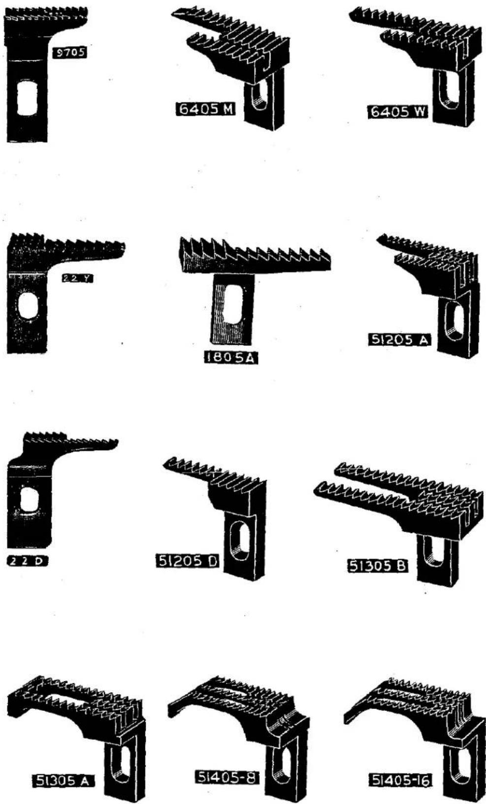
Plate 2- Full Size
natural_image
Pure mechanical component diagram without any text, numbers, or symbols51405B-32

natural_image
Black and white illustration of a mechanical component with grooves and a curved base (no text or symbols)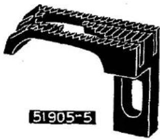
natural_image
Technical drawing of a mechanical bracket or bracket with textured surface and U-shaped cutout (no text or symbols)
natural_image
Pure mechanical component diagram without any text, numbers, or symbols51405B-48

natural_image
Technical illustration of a mechanical component with zigzag grooves and a curved base (no text or symbols)
natural_image
3D mechanical component diagram with no visible text or symbols
natural_image
3D rendering of a mechanical component with grooves and a U-shaped base (no text or symbols)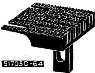
natural_image
Technical illustration of a mechanical component with no visible text or symbols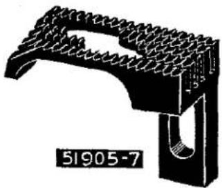
natural_image
3D mechanical component diagram with no visible text or symbols
natural_image
3D architectural model of a bird perched on a bridge structure (no text or symbols visible)Plate 3- Full Size

natural_image
Illustration of a mechanical device with gears and shafts (no text or symbols)35820P
Specify Gauge
natural_image
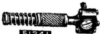
Illustration of a mechanical device with a cylindrical component and handle (no text or symbols)51220 A
natural_image
Illustration of a mechanical clamp or clamp device (no text or symbols visible)6520
natural_image
Illustration of a mechanical device with no visible text or symbols51920
Specify Gauge
natural_image
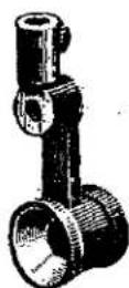
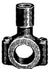
Technical illustration of a mechanical device with no visible text or symbols51420 C
Specify Gauge
natural_image
Illustration of a mechanical lever component (no text or symbols visible)1727A
natural_image
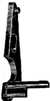
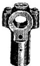
Illustration of a handgun mechanism (no text or symbols visible)51420
Specify Gauge
natural_image
Technical illustration of a mechanical component with no visible text or symbols51520
Specify Gauge

natural_image
Illustration of a mechanical device with a handle and base plate (no text or symbols)51720
Specify Gauge
natural_image
Black-and-white illustration of a handheld device with textured grip and cylindrical body (no text or symbols)51120B
natural_image
Technical illustration of a mechanical clamp or bracket assembly (no text or symbols visible)51720D-64
Plate 4- Full Size
Specify Gauge
natural_image
Black-and-white line drawing of a mechanical lever or lever (no text or symbols)51525

natural_image
Black-and-white illustration of a mechanical device with a curved handle and base (no text or symbols)51725

natural_image
Illustration of a mechanical tool or bracket (no text or symbols visible)51925
Plate 5- Full Size

natural_image
Technical line drawing of a mechanical component with no visible text or symbols51224A

natural_image
Cross-sectional diagram of a mechanical or electrical component with no visible text or symbols51224B

natural_image
Pure electrical circuit lines without any symbols51224 D

natural_image
Pure electrical circuit lines without any symbols51324B
natural_image
Technical line drawing of a mechanical component with no visible text or symbols51424
Specify Gauge
natural_image
Cross-sectional diagram of a mechanical component with internal channels and mounting holes (no text or labels)51524
Specify Gauge
Plate 6- Full Size
natural_image
Pure electrical circuit lines without any symbols51424 C-48
natural_image
Pure electrical circuit lines without any symbols51424B
Specify Gauge

natural_image
Pure electrical circuit lines without any symbols51724
Specify Gauge

natural_image
Pure electrical circuit lines without any symbols51724 D-64
Plate 7- Full Size

natural_image
Pure electrical circuit lines without any symbols6224 B

natural_image
Close-up of a textured wooden panel with circular holes and rectangular cutouts (no visible text or symbols)9224 E

natural_image
Pure electrical circuit lines without any symbols51124 B
natural_image
Pure mechanical component diagram without any text, numbers, or symbols9724

natural_image
Cross-sectional diagram of an electrical component with no visible text or symbols51924
Specify Gauge

natural_image
Pure electrical circuit lines without any symbols6424 W

natural_image
Pure electrical circuit lines without any symbols51124 A

natural_image
Cross-sectional diagram of a mechanical component with internal channels and mounting holes (no text or symbols)51924 B
Specify Gauge
Plate 8- Full Size
natural_image
Illustration of a curved mechanical component with textured surfaces (no text or symbols)51108

natural_image
Illustration of a curved mechanical tool or clamp (no text or symbols visible)51208
natural_image
Simple line drawing of a mechanical tool or bracket (no text or symbols)51208D
natural_image
Illustration of a mechanical clamp or tool (no text or symbols visible)51408
Specify Gauge

natural_image
Illustration of a mechanical tool or caliper (no text or symbols visible)51409

natural_image
Illustration of a mechanical clamp or clamping tool (no text or symbols visible)51409 B
natural_image
Abstract black-and-white line drawing resembling a stylized letter or symbol (no text or symbols present)51508

51708
Specify Gauge

51709
natural_image
Illustration of a stylized tool or tool handle (no text or symbols)51908

natural_image
Illustration of a curved mechanical component with textured surfaces (no text or symbols)51908 A
Specify Gauge
Specify Gauge
natural_image
Simple line drawing of a curved mechanical or tool handle (no text or symbols)51909

natural_image
Simple line drawing of a tool handle (no text or symbols)51909 B

natural_image
Illustration of a curved mechanical tool or tool handle (no text or symbols visible)51909 A
Specify Gauge.
Specify Gauge
Plate 9- Full Size

Plate 10- Full Size
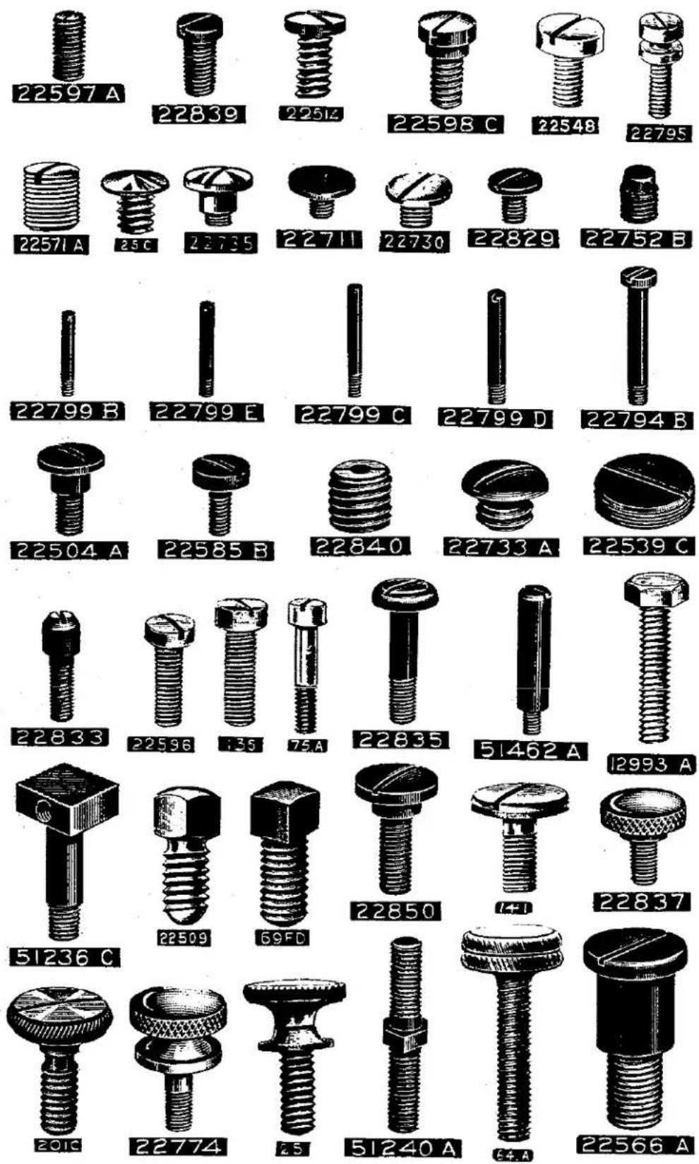
Plate 11- Full Size
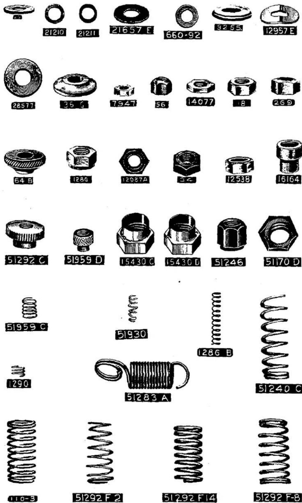
Plate 12- Full Size
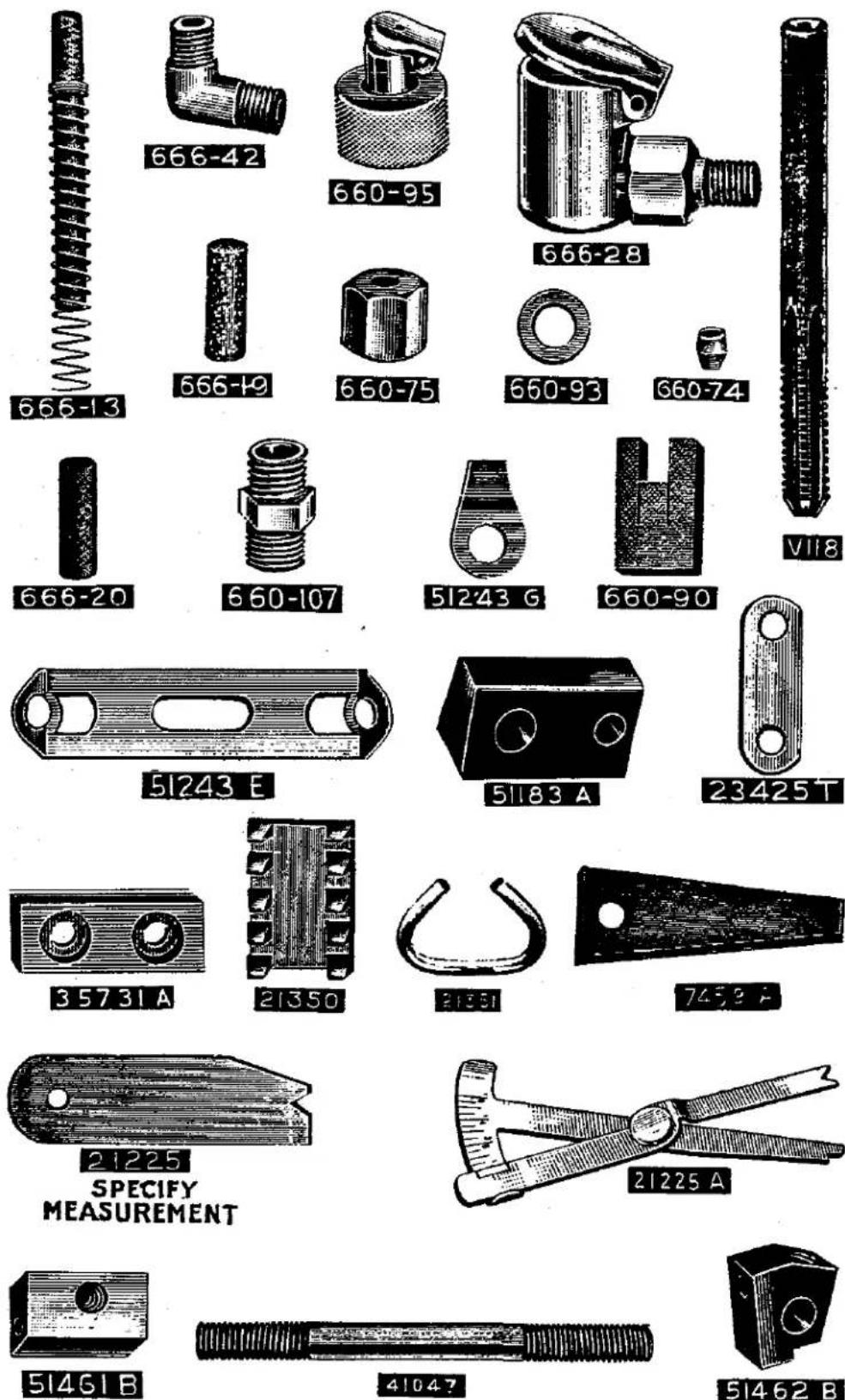
Plate 13- Full Size

Plate 14- Full Size
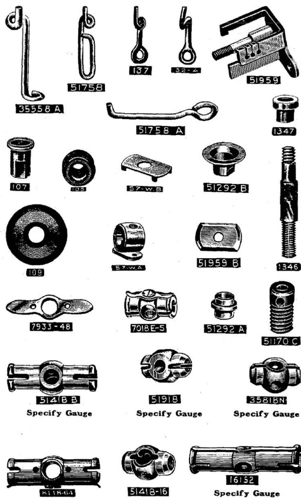
Plate 15- Full Size

Plate 16- Full Size

Plate 17- Full Size

Plate 18- One-half Size
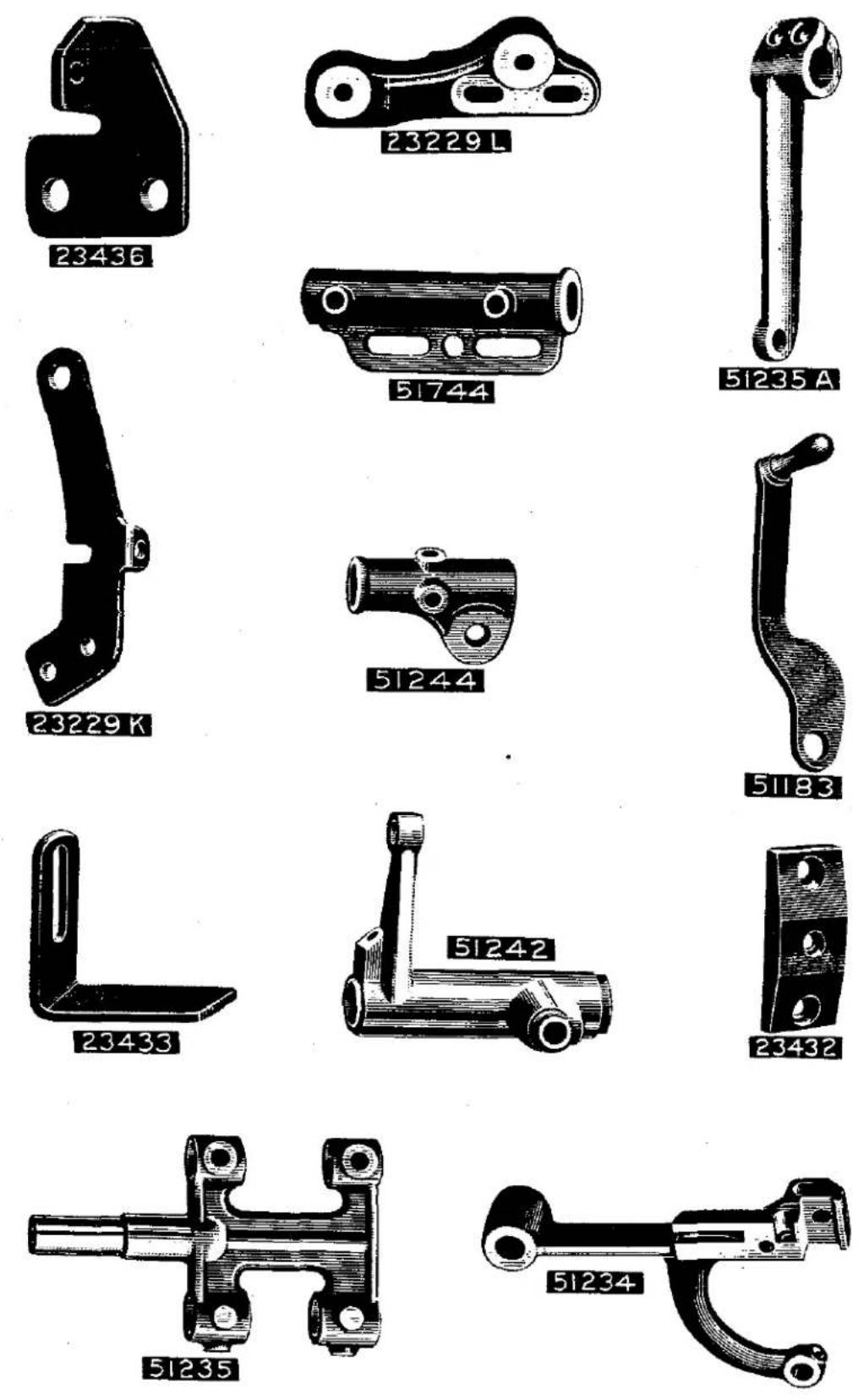
Plate 19- One-half Size

Plate 20- One-half Size

Plate 21- One-half Size
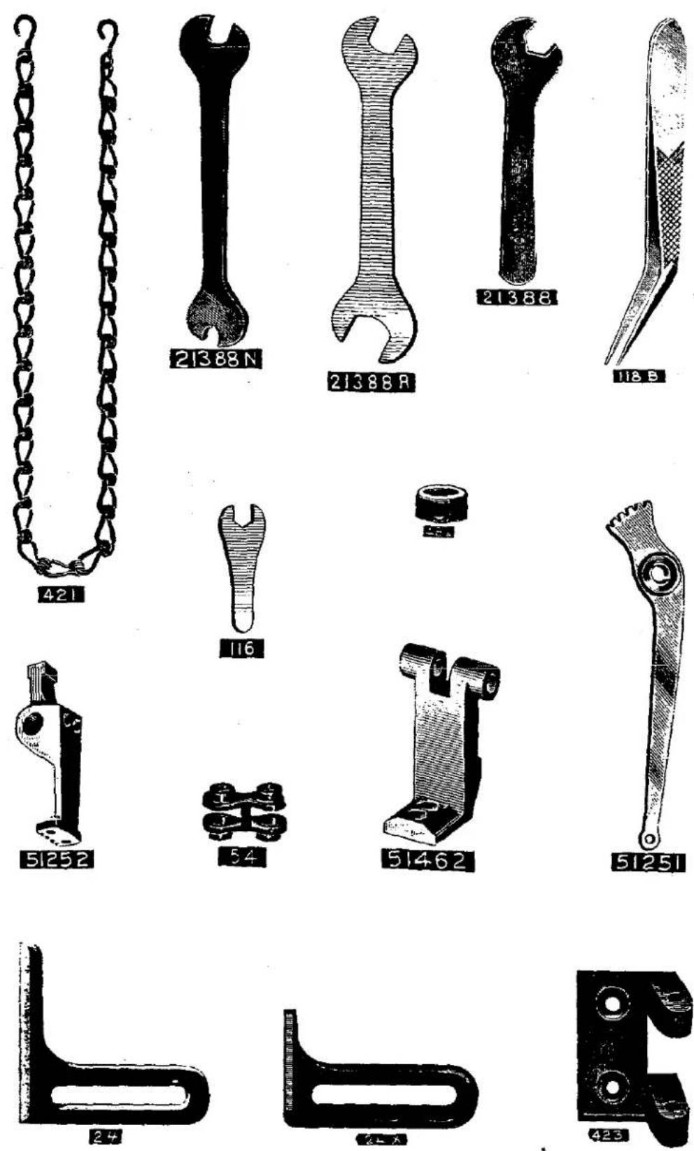
Plate 22- One-half Size

Plate 23- One-half Size
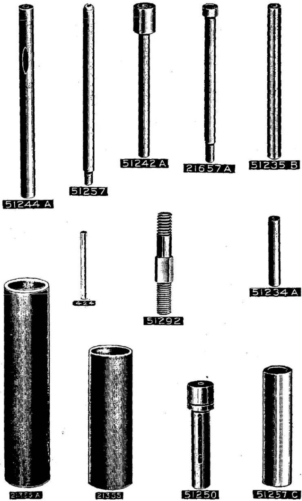
Plate 24- One-half Size
line
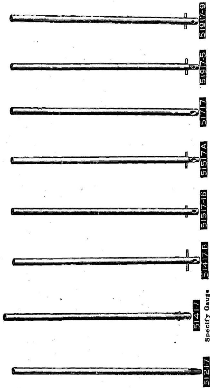
| Series | Value | | ------------ | ----- | | 51917-9 | + | | 51917-5 | - | | 51717 | + | | 51517A | - | | 51517-16 | + | | 51417B | - | | 51217 | + |Plate 25- One-half Size

natural_image
Technical drawing of a mechanical flange with bolt holes and central bore (no text or symbols)51461A
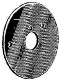
natural_image
Circular object with a central hole and three labeled points (1, 2, 3) on its surface, resembling a mechanical or electronic component (no text or symbols visible)51461
5123

51423
51213
51413

51513
51713

51913

natural_image
Technical drawing of a mechanical component with concentric rings and mounting holes (no text or symbols)51243A
51216A
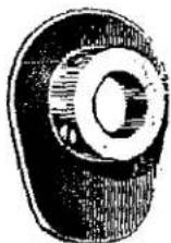
natural_image
Technical drawing of a mechanical component with a flanged end and cylindrical top (no text or symbols)51216B

51772
Specify Gauge
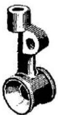
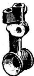
natural_image
Illustration of a mechanical device with threaded shaft and pressure gauge (no text or symbols)51241
natural_image
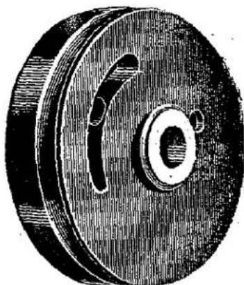
Illustration of a mechanical pulley or wheel with a central bore and side slots (no text or symbols)51321
natural_image
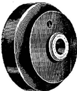
Illustration of a mechanical pulley or wheel with concentric rings and central bore (no text or symbols)51321A
natural_image
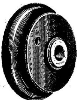
Illustration of a pulley with two holes and a central bore (no text or symbols)51221
Plate 26- One-half Size

Plate 27- One-fourth Size
natural_image
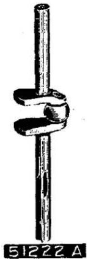
Simple line drawing of a vertical cylindrical object with a coiled loop, labeled '51222 A' at the base (no other text or symbols)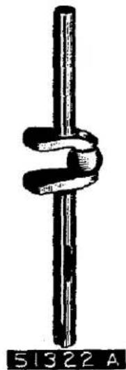
natural_image
Simple line drawing of a twisted rope or rope knot with no text or symbols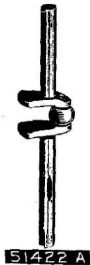
natural_image
Simple line drawing of a rope tied with a vertical rod, no text or symbols present
natural_image
Silhouette of a mechanical bracket or bracket with no visible text or symbols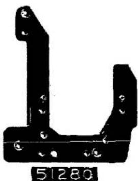
natural_image
Black metal bracket with bolt holes and a small number 51280 below (no text or symbols on the object itself)
natural_image
Metal bracket component with mounting holes and a base labeled 51280A (no other text or symbols)
natural_image
Black metal T-shaped object with circular holes and a small circular feature, labeled '51281 C-226' at bottom (no other text or symbols)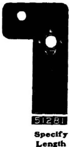
text_image
51281 Specify Length
text_image
51281 E-226Plate 28- One-fourth Size
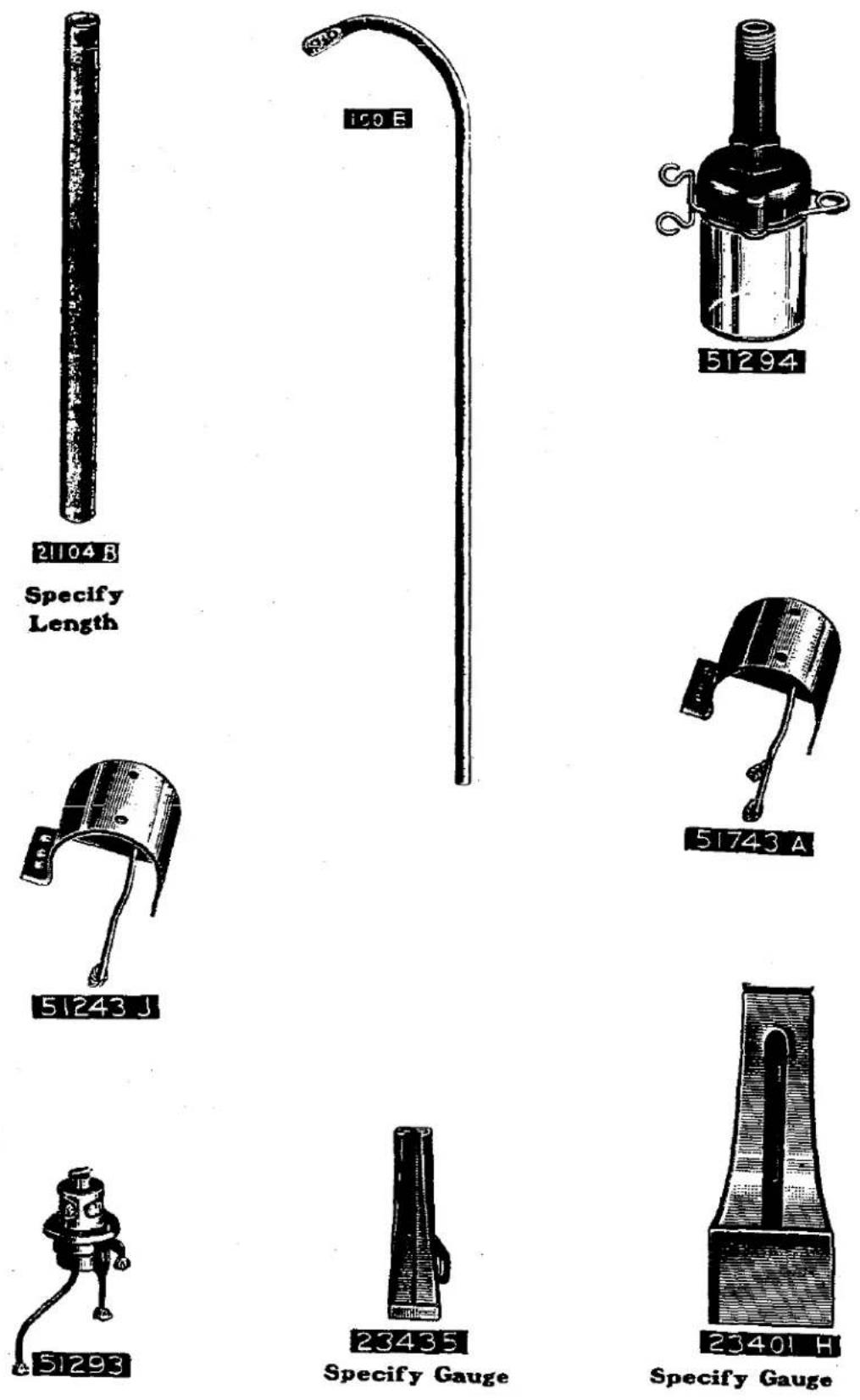
Plate 29- One-fourth Size
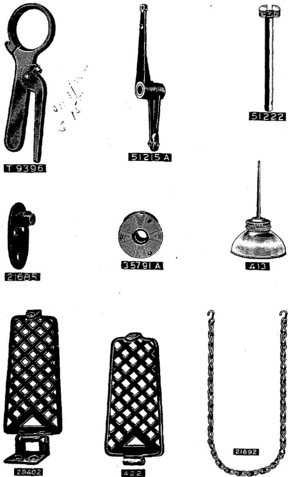
Plate 30- One-fourth Size
text_image
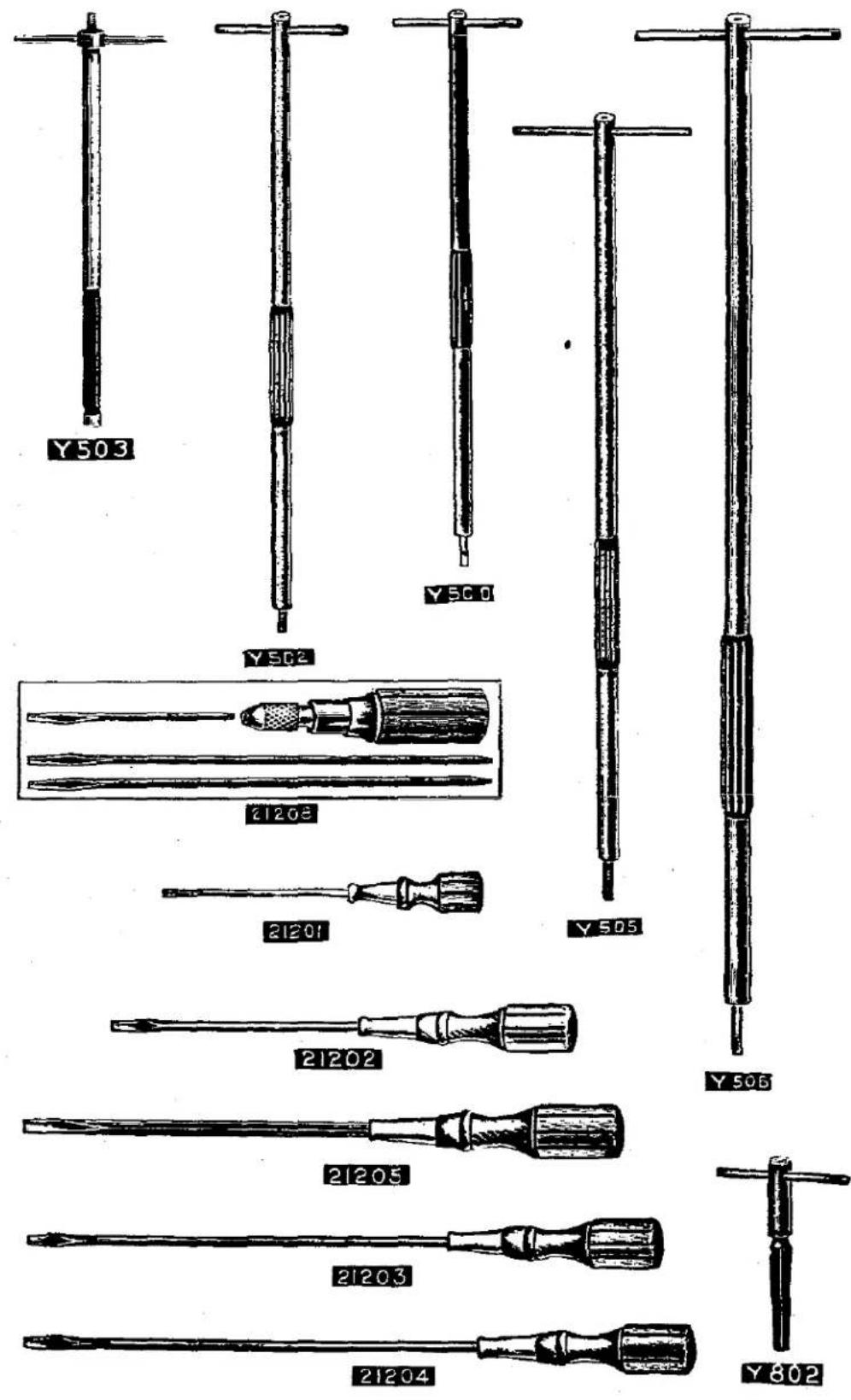
Y503 Y502 Y500 21203 21201 Y505 21202 Y506 21205 21203 21204 Y802Plate 31- One-eighth Size
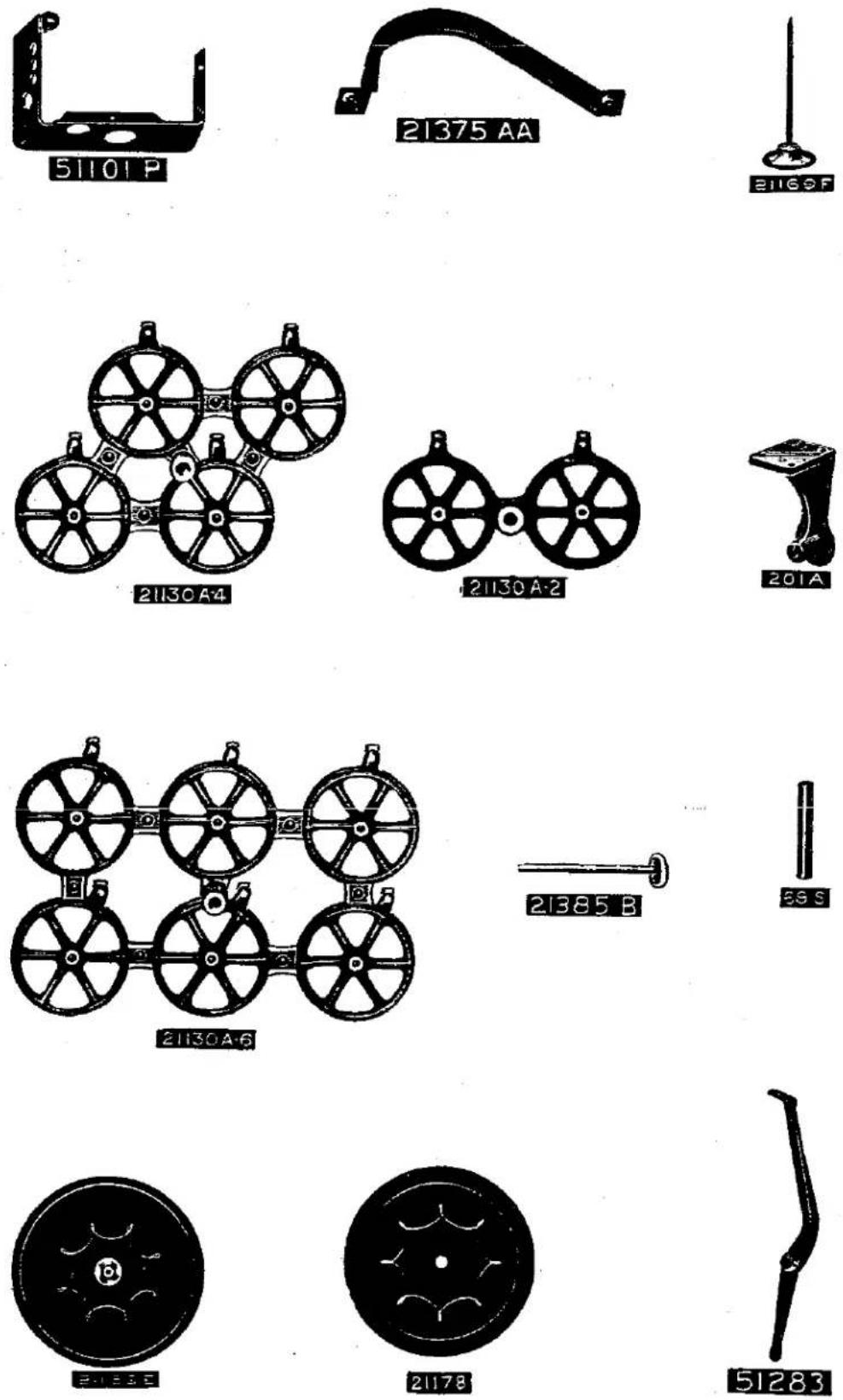
Plate 32- One-eighth Size

natural_image
Illustration of a wooden box with a paper cutout and a small figure inside, labeled '21377 AD' (no other text or symbols)

natural_image
Illustration of a mechanical device with a labeled part '7' and reference number '21377 AE' (no other text or symbols)
natural_image
Mechanical linkage device with a labeled part '21693A' (no other text or symbols visible)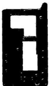
text_image
151101
natural_image
Pure electrical circuit lines without any symbols51201
natural_image
Abstract black-and-white geometric shape resembling a stylized letter or symbol (no text or symbols present)51201A

natural_image
Abstract black-and-white geometric shape with no text or symbols51701
LIST OF PARTS
| Symbol to Order by | The figures in the last column refer only to the plates illustrating the parts and are not to be used in ordering. Refer to pink insert for prices. | Plate No. |
| 16 | Feed Crank Link Ferrule | 15 |
| 18 | Looper Connecting Rod Nut, right thread; also for No.35754 | 11 |
| 20 | Feed Crank Stud Washer | 11 |
| 21 | Feed Crank Link Pin | 17 |
| 22 D | Feed Dog, for Style 51200 E (screw No.93) | 1 |
| 22 Y | Feed Dog, for Style 51100 B (screw No.93) | 1 |
| 24 | Edge Guide, for Style 51300 A | 21 |
| 24 X | Edge Guide, for Styles in Class 51100; also Style 51200 C | 21 |
| 25 | Thumbscrew, for cloth plate edge guides | 10 |
| 25 B | Screw, for angular strip guide on Styles 51400 B, 51400 C, 51700 C, 51700 D | 9 |
| 25 C | Screw, 9/32 inch long, for cloth plate attachments | 10 |
| 28 | Screw, for lap seam feller upper scrolls | 9 |
| 34 | Knee Lifter Stop Screw Nut | 11 |
| 36 G | Looper Connecting Rod Ball Stud Washer | 11 |
| 43 | Feed Lift Eccentric and Looper Avoiding Eccentric, for styles in Classes 51400, 51700; also Styles 51200 A, 51200 D, 51200 E, 51200 G, 51900 A (spot screw No.96) | 16 |
| 43 C | Feed Lift Eccentric and Looper Avoiding Eccentric, for Styles in Classes 51300, 51500; also Styles 51100 B, 51200 B, 51200 C, 51900 B (spot screw No.96) | 16 |
| 52 A | Frame Needle Thread Eyelet (screw No.98 A) | 14 |
| 54 | Needle Lever Link | 21 |
| 56 | Needle Clamp Nut, for styles in Classes 51100, 51200, 51300 | 11 |
| 57 WA | Needle Bar Thread Nipper Collar, for Styles in Class 51100 (screw No.88) | 14 |
| 57 WB | Needle Bar Thread Nipper Plate | 14 |
| 57 WD | Needle Bar Thread Nipper Stud | 9 |
| 64 A | Presser Spring Regulating Screw | 10 |
| 64 B | Presser Spring Regulating Screw Lock Nut | 11 |
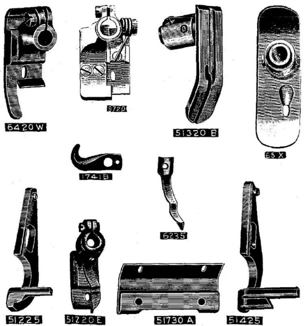
| 65 X | Presser Foot, hinged, for Styles 51100 A, 51100 C (set screw No.88, hinge screw No. 86 X) | 4 |
| 65 XC | Presser Foot Bottom, for Styles 51100 A, 51100 C | - |
| 65 XD | Presser Foot Shank, for Styles 51100 A, 51100 C, 51300 B | - |
| 69 S | Spool Pin, 4 inches long, for thread stands | 31 |
| □ 69 FD | Screw, square head, cup point, 5/16 inch diam. 18 threads, 5/8 inch long, for thread stand seat; also for Nos.21685, 21693 F, 21693 K | 10 |
| 73 | Set Screw, for loopers | 9 |
| 75 | Screw, for hand lifter plate, on styles in Class 51100 | 9 |
| 75 A | Screw, for needle lever connecting rod bearing, lower; also for No.51243 A | 10 |
| 77 | Set Screw, for feed crank link pin; also for Nos.1286, 1286 A, 51420 C, 51720, 51720 D | 9 |
| 78 | Set Screw, for lower needle lever link pin | 9 |
| 79 | Screw, for take-up thread eyelets; also for No.51462 | 9 |
| 80 | Screw, for cloth plates | 9 |
LIST OF PARTS
| Symbol to Order by | The figures in the last column refer only to the plates illustrating the parts and are not to be used in ordering. Refer to pink insert for prices. | Plate No. |
| 86 X | Presser Foot Hinge Stud,for Styles 51100 A, 51100 C,51300 B | 9 |
| 87 | Screw,countersunk head,for throat plates ... | 9 |
| 87 U | Screw,for needle thread take-up wires;also for Nos.51260,51260 A,51460,51460 A,51960, 51960 A | 9 |
| 88 | Screw,for looper rocker cone;also for Nos.57 WA, 65 X, 161,51283 C,51320 B | 9 |
| 88 A | Set Screw,for needle bars;also for No.23432. | 9 |
| 88 B | Screw,for looper rocker frame sleeves | 9 |
| 89 | Spot Screw,for take-up;also for Nos.7018 E-5, 8118-64,35818 N,51418-16,51418 B-32, 51418 B-48,51461 A,51918 | 9 |
| 90 | Screw,for louver cover;also for Nos.10685, 23215 BB,23322 AB,23322 AC,23439,51170 B, 51270 A,51282 A | 9 |
| 91 | Clamp Screw,for presser feet | 9 |
| 91 A | Screw,for presser foot yielding spring guide on Style 51200 E | 9 |
| 93 | Screw,for feed dogs;also for Nos.23229 L, 51235 A,51244 B,51759 | 9 |
| 93 A | Screw,for feed lift eccentric oil tube clamp; also for Nos.2603 K,51243 G,51959 | 9 |
| 94 | Screw,for looper lever connection guard; also for Nos.7459 A,23401 H,23432,23433, 35558 A,51159,51243 J,51758 | 9 |
| 95 | Screw,for main shaft collar | 9 |
| 96 | Spot Screw,for feed lift eccentric and looper avoiding eccentric;also for Nos.51242 C,51244,51343,51443,51744 | 9 |
| 97 | Screw,for needle lever ball stud guide fork; also for Nos.51243 A,51293 | 9 |
| 97 A | Screw,for needle lever connecting rod bear-ing,upper;also for Nos.51243 A,51741, 51741 B | 9 |
| 98 | Set Screw,3/16 inch long,without pilot,for needles;also for Nos.482,51235,51244, 51343,51433,51443,51744 | 9 |
| 98 A | Screw,for frame thread eyelet No. 52 A | 9 |
| 100 B | Thread Stand Wire,16 inches long (set screw No.22632 F-24) | 28 |
| 107 | Strip Tension Ferrule,for Styles 51400 D, 51700 D | 14 |
| 108 | Strip Tension Nut | 14 |
| 109 | Tension Disk | 14 |
| 110-3 | Tension Spring, .040 inch diam.wire,for tape reel axle;also for No.21182 N | 11 |
| 116 | Wrench,for needle clamp nut | 21 |
| 118 B | Thread Tweezers | 21 |
| V118 | Tap,marked "X2" for No.22521 | 12 |
| 136 | Screw,for facing strip folder bracket, on Styles 51400 B,51400 D,51700 D | 10 |
| 137 | Needle Thread Controller Eyelet,for styles in Classes 51200,51300,51400,51500,51900.. | 14 |
| 138 | Needle Thread Controller Eyelet Screw | 9 |
| 141 | Screw,for needle thread controller lever ... | 10 |
| 158 A | Frame Looper Thread Eyelet (screw No.98 A) | 20 |
| 161 | Collar,for binding holder disk,on Styles 51200 A,51200 B (screw No.88) | 15 |
LIST OF PARTS
| Symbol to Order by | The figures in the last column refer only to the plates illustrating the parts and are not to be used in ordering. Refer to pink insert for prices. | Plats No. |
| 187 A | Screw,for presser foot chain knife on Style 51200 D | 9 |
| 201 A | Tape Reel Frame,for styles in Class 51700; also Styles 51400 B,51400 C,51400 D | 31 |
| 201 C | Thumbscrew,for tape reel axle | 10 |
| 269 | Looper Connecting Rod Nut,left thread;also for No.51236 C | 11 |
| 402 | Hand Lifter Screw Pin,for styles in Class 51100 | 9 |
| 413 | Oil Can,complete | 29 |
| 421 | Foot Lifter Lever Chain, 38 inches long | 21 |
| 422 | Foot Lifter Treadle | 29 |
| 423 | Foot Lifter Treadle Base | 21 |
| 424 | Foot Lifter Treadle Pin (screw No.22813) | 23 |
| 482 | Feed Rocker Shaft Collar (screw No.98) | 21 |
| Y500-257 | Expansion Reamer,for needle bar bearings, size .257 inch | 30 |
| Y502-319 | Expansion Reamer,for upper presser bar bearing,size .319 inch | 30 |
| Y503-319 | Expansion Reamer,for lower presser bar bearing,size .319 inch | 30 |
| Y505-407 | Expansion Reamer,for looper rocker and feed rocker shaft bearings,size .407 inch | 30 |
| Y506-530 | Expansion Reamer,for main shaft bearings, size .530 inch | 30 |
| 531 | Set Screw,for looper lever shaft bushing, front;also for Nos.23229 K,51242 A,51252, 51751 | 9 |
| 604 | Screw,for thread controller lever connec-tion thread guide | 9 |
| 605 A | Screw,for needle stop plate,on styles in Class 51700 | 9 |
| □ 650-10 | Stove Bolt,flat head,1/4 x 1 1/4 inches | - |
| □ 650-24 | Stove Bolt,flat head,1/4 x 3 inches | - |
| □ 650-28 | Stove Bolt,flat head,1/4 x 3 1/2 inches | - |
| 660-74 | Connection Sleeve,for oil line to main bearings | 12 |
| 660-75 | Connection Sleeve Coupling | 12 |
| 660-84 | Tube,left,for oil line to main shaft bearings | 22 |
| 660-85 | Tube,middle | 22 |
| 660-86 | Tube,right | 22 |
| 660-90 | Felt Wiper,for looper lever eccentric connection | 12 |
| 660-92 | Leather Washer,upper,for main shaft oil gauge | 11 |
| 660-93 | Leather Washer,lower | 12 |
| 660-94 | Glass Tube,for main shaft oil gauge | 22 |
| 660-95 | Cap,for main shaft oil gauge | 12 |
| 660-96 | Frame,for main shaft oil gauge | 22 |
| 660-103 | Oil Line "T" Coupling,for middle main shaft bearing | 22 |
| 660-104 | Oil Line "T" Coupling,for inner right main shaft bearing | 22 |
| 660-105- | Oiling Tube,for feed crank link | 22 |
| 660-107 | Oil Line Coupling,for left main shaft bearing | 12 |
| 666-13 | Felt Wick,spring pressed,for main shaft bearings | 12 |
| 666-16 | Reservoir,for oil drain assembly | - |
□ See Page 8.
44..
LIST OF PARTS
| Symbol to Order by | The figures in the last column refer only to the plates illustrating the parts and are not to be used in ordering. Refer to pink insert for prices. | Plate No. |
| 666-19 | Felt Wick,for needle lever connecting rod lower bearing;also for Nos.51236,51245 ... | 12 |
| 666-20 | Felt Wick,for looper avoiding eccentric link | 12 |
| 666-28 | Oil Cup,for needle lever stud ... | 12 |
| 666-29 | Felt Wick,for needle lever stud ... | 22 |
| 666-42 | Coupling, "L"type,for outer right main shaft bearing ... | 12 |
| 719 | Set Screw,for needle lever stud;also for No.51250 B ... | 9 |
| Y802 | Taper Reamer,for needle lever link and feed crank link pins ... | 30 |
| 1248 | Feed Crank Link Shim,leather;also for No. 51245 ... | 17 |
| 1280 | Looper Rocker Stud Nut,for styles in Class 51700 ... | 11 |
| 1286 | Needle Lever Link Pin Assembly;one each Nos.1286 A,1286 B,12964 C,22560 ... | 17 |
| 1286 A | Needle Lever Link Pin (set screw for upper link pin No.77,set screw for lower link pin No.78) ... | 17 |
| 1286 B | Needle Lever Link Pin Spring (screw No. 22560) ... | 11 |
| 1290 | Needle Bar Thread Nipper Spring,for styles in Class 51100 ... | 11 |
| 1346 | Strip Tension Post,for Styles 51400 D, 51700 D ... | 14 |
| 1347 | Tension Post Ferrule,for strip tension on Styles 51400 D,51700 D ... | 14 |
| 1361 A | Presser Spring Pin ... | 17 |
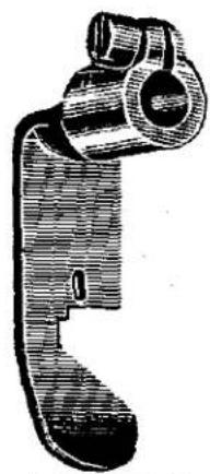
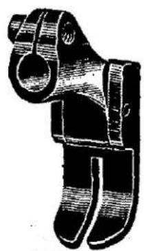
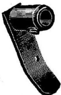
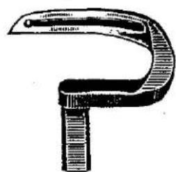
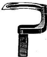
| 1727 A | Presser Foot,hinged bottom,for Style 51200 D (clamp screw No. 91) ... | 3 |
| 1741 B | Presser Foot Chain Knife,for Style 51200 D (screw No.187 A) ... | 4 |
| 1805 A | Feed Dog,for Styles 51100 A,51100 C (screw No.93) ... | 1 |
| 2603 K | Edge Guide Assembly,for Style 51200 D; one each Nos.14775 A,16675,16676,22768,22772 (screw No.93 A) ... | 19 |
| 6224 B | Throat Plate,for Style 51200 E (screw No.87) ... | 7 |
| 6235 | Yielding Spring Guide for presser foot on Style 51200 E (screw No.91 A) ... | 4 |
| 6405 M | Feed Dog,for Style 51200 B (screw No.93) ... | 1 |
| 6405 W | Feed Dog,for Style 51200 C (screw No.93) ... | 1 |
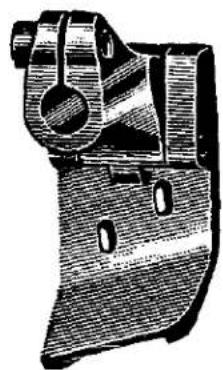
| 6420 W | Presser Foot,hinged bottom,for Styles 51200 B,51200 C (clamp screw No.91) ... | 4 |
| 6424 W | Throat Plate,for Style 51200 C (screw No.87) | 7 |
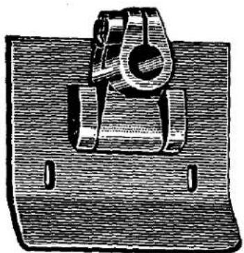
| 6520 | Presser Foot,hinged bottom,for Style 51300 A (clamp screw No.91) ... | 3 |
| 7018 E-5 | Needle Holder,for No.18 gauge Style 51500 A (spot screw No.89,needle set screw No.98). | 14 |
| 7459 A | Take-up Thread Eyelet Spring,for styles in Classes 51200,51300,51400,51500,51700, 51900 (screw No.94) ... | 12 |
| 7933-48 | Needle Stop Plate,for Nos.56 and 64 gauge styles in Class 51700 (screws No.605 A)... | 14 |
| 7947 | Feed Crank Link Nut;also for No.51245 ... | 11 |
LIST OF PARTS
| Symbol to Order by | The figures in the last column refer only to the plates illustrating the parts and are not to be used in ordering. Refer to pink insert for prices. | Plate No. |
| 8118-64 | Needle Holder,for No.64 gauge styles in Class 51700 (spot screw No.89,needle set screw No.98) | 14 |
| 9224 E | Throat Plate,for Style 51300 A (screw No.87) | 7 |
| 9255 | Facing Strip Folder Washer,on Styles 51400 B, 51400 D,51700 D;also for No.23436 | 11 |
| T9396 | Wrench,for main shaft bearing housing | 29 |
| 9705 | Feed Dog,for Style 51200 G (screw No.93) | 1 |
| 9720 | Presser Foot,for Style 51200 G (clamp screw No.91) | 4 |
| 9724 | Throat Plate,for Style 51200 G (screw No.87) | 7 |
| 10685 | Throat Plate Support Thread Eyelet,for Styles in Class 51100 (screw No.90) | 20 |
| 12538 | Looper Rocker Ball Stud Nut,for styles in Classes 51100,51200,51300,51400,51500, 51900 | 11 |
| 12935 A | Screw,for adjusting presser foot bottom on Style 51900 A | 9 |
| 12957 E | Spring Washer,for folder swinging arm on styles in Class 51700 and Styles 51400 B, 51400 C;also for No.23437 A | 11 |
| 12964 C | Needle Lever Link Pin Ball | 17 |
| 12987 A | Looper Rocker Cone Nut | 11 |
| 12993 A | Stop Screw,for knee lifter interlocking arm; also for No.21693 K | 10 |
| 14077 | Looper Rocker Ball Stud Nut,for styles in Class 51700;also for No.22835 | 11 |
| 14775 A | Edge Guide Spring,for Style 51200 D | — |
| 15430 C | Needle Lever Connecting Rod Nut,left thread, | 11 |
| 15430 D | Needle Lever Connecting Rod Nut,right thread; also for No.21693 J | 11 |
| 15465 F | Looper Rocker Cone (screw No.88,nut No. 12987 A) | 17 |
| 16152-56 | Needle Holder,for No.56 gauge Style 51700 C (spot screw No.89,needle set screw No.98). | 14 |
| 16164 | Tension Post Ferrule,for styles in Class 51100 | 11 |
| 16675 | Edge Guide Roller,for Style 51200 D | 15 |
| 16676 | Edge Guide Roller Pin | 17 |
| 21104 A | Thread Stand Base (screw No.22509) | 32 |
| 21104 B-11 | Thread Stand Rod,11 inches long | 28 |
| 21130 A-2 | Thread Stand Seat,2 spools | 31 |
| 21130 A-4 | Thread Stand Seat,4 spools | 31 |
| 21130 A-6 | Thread Stand Seat,6 spools | 31 |
| 21169 E | Binding Holder Disk, for Styles 51200 A, 51200 B | 31 |
| 21169 F | Binding Holder Base | 31 |
| 21178 | Tape Reel Disk,8 inches diam.for styles in Class 51700;also Styles 51400 B,51400 C, 51400 D | 31 |
| 21182 K | Strip Tension Plate,outer,for Styles 51400 D, 51700 D | — |
| 21182 L | Strip Tension Plate,inner | — |
| 21182 N | Strip Tension Assembly,for Styles 51400 D, 51700 D;one each Nos.21182 K,21182 L, 21182 P,and two each Nos.107,108,110-3, 1346,1347 | 20 |
| 21182 P | Strip Tension Base | — |
LIST OF PARTS
| Symbol to Order by | The figures in the last column refer only to the plates illustrating the parts and are not to be used in ordering. Refer to pink insert for prices. | Plate No. |
| 21201 | Screw Driver,9/64 inch round blade,length overall 7 5/8 inches | 30 |
| 21202 | Screw Driver,7/32 inch round blade,length overall 11 inches | 30 |
| 21203 | Screw Driver,7/32 inch round blade,length overall 15 inches | 30 |
| 21204 | Screw Driver,1/4 inch round blade,length overall 15 inches | 30 |
| 21205 | Screw Driver,3/8 inch octagon blade,length overall 14 inches | 30 |
| 21208 | Screw Driver Set,three detachable blades | 30 |
| 21210 | Looper Collar,.040 inch thick | 11 |
| 21210 A | Looper Collar,.020 inch thick | - |
| 21211 | Looper Collar,.054 inch thick | 11 |
| 21225-1/8 | Looper Adjusting Gauge,1/8 inch measurement. | 12 |
| 21225-5/32 | Looper Adjusting Gauge,5/32 inch measurement | 12 |
| 21225 A | Looper Gauge,universal adjustment | 12 |
| 21261 | Leather Belt,flat,1 inch wide,63 inches long, includes belt fastener No.21350 | - |
| 21262 | Leather Belt,round,9/32 inch diameter,44 inches long, includes wire belt hook No. 21351 | - |
| 21350 | Belt Fastener,malleable iron,for 1 inch flat belt | 12 |
| 21351 | Belt Hook,wire,for 9/32 inch round belt | 12 |
| 21355 | Chair Leg Extension,4 inches long | 23 |
| 21355 A | Chair Leg Extension,6 inches long | 23 |
| □ 21368 | Washer,1/4 inch,for flat head stove bolts... | - |
| 21371 B | Table Top,48 inches long,16 1/8 inches wide, 1 3/4 inches thick | - |
| 21371 M | Individual Power Table,blank top,without electric transmitter or electric fittings | - |
| 21371 AN-12 | Individual Power Table,equipped with 3000 R.P.M. 1/2 H.P. 115 volt,D.C.transmitter (specify diam.of transmitter pulley) | - |
| 21371 AN-13 | Individual Power Table,equipped with 3000 R.P.M. 1/2 H.P. 230 volt,D.C.transmitter.. | - |
| 21371 AP-15 | Individual Power Table,equipped with 3450 R.P.M. 1/2 H.P. 220 volt,3 phase,60 cycle, A.C. transmitter (specify diam. of trans- mitter pulley) | - |
| 21371 AQ-17 | Individual Power Table,equipped with 3300 R.P.M. 1/2 H.P.,110 volt,single phase,60 cycle,A.C. transmitter (specify diam. of transmitter pulley) | - |
| 21371 AQ-18 | Individual Power Table,equipped with 3300 R.P.M.1/2 H.P. 220 volt,single phase,60 cycle,A.C. transmitter | - |
| 21375 AA | Pulley Oil Guard,for styles in Classes 51200,51300,51400,51500,51700,51900 | 31 |
| 21377 AD | Tray,hinged,for machines without attachments that overhang front of cloth plate | 32 |
| 21377 AE | Tray,hinged,for machines with attachments that overhang front of cloth plate | 32 |
| 21377 AF | Tray,hinged,for machines which are installed below surface of table and which do not have attachments overhanging front of cloth plate | - |
| 21385 B | Tape Reel Axle (screw No.201 C) | 31 |
□ See Page 8.
LIST OF PARTS
| Symbol to Order by | The figures in the last column refer only to the plates illustrating the parts and are not to be used in ordering. Refer to pink insert for prices. | Plate No. |
| 21388 | Wrench,for 3/8 inch hexagon nuts | 21 |
| 21388 N | Wrench,double end,3/16 and 5/16 inch openings | 21 |
| 21388 R | Wrench,double end,3/8 and 1/2 inch openings | 21 |
| 21394 | Utility Grinder,including emery wheel 5 inches diam,1/4 inch face,round belt drive, recommended speed 3000 R.P.M. | - |
| □ 21394 G | Emery Wheel,5 inches diam.1/4 inch face,3/8 inch hole,grade "M",emery 60 | - |
| □ 21394 H | Emery Wheel,5 inches diam.1/2 inch face,3/8 inch hole,grade "M",emery 60 | - |
| 21394 K | Utility Grinder,including emery wheel 5 inches diam.1/2 inch face,round belt drive, recommended speed 3000 R.P.M. | - |
| 21657-1 | Tension Release Disk Separator,for styles in Classes 51200,51300 | 20 |
| 21657-2 | Tension Release Disk Separator,for styles in Classes 51400,51500,51700 | 20 |
| 21657-3 | Tension Release Disk Separator,for styles in Class 51900 | 20 |
| 21657 A | Tension Release Rock Shaft,for styles in Classes 51200,51300,51400,51500,51700, 51900 | 23 |
| 21657 B | Tension Release Rock Shaft Connection (clamp screw No.22585) | 17 |
| 21657 C | Tension Release Rock Shaft Lever (clamp screw No.22596,stud No.22594) | 20 |
| 21657 D | Tension Release Rock Shaft Lever Link (stud No.22515) | 20 |
| 21657 E | Tension Release Disk Separator Washer,for styles in Classes 51200,51300 | 11 |
| 21685 | Knee Lifter Plate (set screw No.69 FD) | 29 |
| 21692 | Knee Lifter Chain,18 1/2 inches long | 29 |
| 21693 A | Knee Lifter Assembly; includes one each Nos.15430 D,21685,21693 B,21693 C,21693 D, 21693 F,21693 G,21693 H,21693 J,21693 K, 21693 T,22622;two each Nos.34,650-10, 12993 A;three No.69 FD and four No.28577 . | 32 |
| 21693 B | Knee Lifter Shaft | - |
| 21693 C | Knee Lifter Frame | - |
| 21693 D | Knee Lifter Shaft Hanger,rear,lower section (bolt No.650-10,compensating washer No.28577). | - |
| 21693 F | Knee Lifter Interlocking Forked Arm (set screw No.69 FD) | - |
| 21693 G | Knee Lifter Interlocking Arm,with engaging pin (set screw No.22622,stop screw No.12993 A,lock nut No.34) | - |
| 21693 H | Knee Lifter Interlocking Arm Pivot Pin, 1 5/8 inches long | - |
| 21693 J | Knee Lifter Plate Rod (lock nut No.15430 D). | - |
| 21693 K | Knee Lifter Chain Arm (set screw No.69 FD, stop screw No.12993 A,lock nut No.34) | - |
| 21693 T | Knee Lifter Shaft Hanger,rear,upper section. | - |
| 21756 G | Screw Pin,for oil drain assembly | 9 |
| 22504 A | Stud,for folder swinging arm,on styles in Class 51700;also Styles 51400 B,51400 C... | 10 |
LIST OF PARTS
| Symbol to Order by | The figures in the last column refer only to the plates illustrating the parts and are not to be used in ordering. Refer to pink insert for prices. | Plate No. |
| ☐ 22509 | Set Screw,square head,cup point,5/16 inch diam. 18 threads,1/2 inch long,for thread stand base.... | 10 |
| 22513 | Screw,for presser bar connection guide plate | 9 |
| 22514 | Screw,7/16 inch long,for cloth plate attachments.... | 10 |
| 22515 | Stud,for tension release rock shaft lever link.... | 9 |
| 22519 | Set Screw,nexagon head,for needle lever ball stud.... | 9 |
| 22521 | Screw,plus size,for cloth plates,tap No.V118 | 9 |
| 22524 | Screw,for upper crank chamber cover.... | 9 |
| 22525 | Screw,.010 inch plus size,length overall 5/16 inch;otherwise same as No.87.... | 9 |
| 22539 C | Plug Screw,for cloth plates.... | 10 |
| 22548 | Screw,for facing strip folder.... | 10 |
| 22560 | Screw,for needle lever link pin spring.... | 9 |
| 22560 B | Screw,for feed bar;also for No.51462 B.... | 9 |
| 22566 A | Stud, for lifter lever.... | 10 |
| 22569 | Screw,for feed crank link;also for Nos.35791 A,51245.... | 9 |
| 22570 | Screw,fillister head,for throat plates.... | 9 |
| 22571 A | Plug Screw,for main shaft oil reservoir.... | 10 |
| 22580 | Set Screw,9/64 inch long, for outer needles on Style 51900 B.... | 9 |
| 22585 | Clamp Screw,for tension release rock shaft connection;also for No.23437 B.... | 9 |
| 22585 B | Screw,for needle guards.... | 10 |
| 22591 | Set Screw,for looper lever ball stud.... | 9 |
| 22594 | Stud,for tension release rock shaft lever.. | 9 |
| 22596 | Clamp Screw,for tension release rock shaft lever.... | 10 |
| 22597 | Spot Screw,for pulleys.... | 9 |
| 22597 A | Set Screw,for pulleys.... | 10 |
| 22598 C | Stud,for tension release disk separator on styles in Classes 51200,51300.... | 10 |
| 22622 | Set Screw,for knee lifter interlocking arm . | 9 |
| ☐ 22632 F-24 | Screw,square head,cup point,3/16 inch diam. 3/8 inch long,24 threads to inch,for thread stand wires.... | 9 |
| 22711 | Screw,for looper thread guard.... | 10 |
| 22726 A | Screw,for cloth plate cover spring.... | 9 |
| 22730 | Screw,for frame needle thread guide No.51758 A on styles in Class 51700.... | 10 |
| 22733 A | Plug Screw,for presser bar bearing.... | 10 |
| 22735 | Screw,for binder bracket on Style 51200 B.. | 10 |
| 22752 | Set Screw,with pilot,for middle needle on Nos. 8 and 9 gauge Style 51900 B.... | 9 |
| 22752 A | Set Screw,with pilot,for middle needle on Nos.5,6 and 7 gauge styles in Class 51900. | 9 |
| 22752 B | Screw,for adjusting presser foot bottom on styles in Classes 51400,51700.... | 10 |
| 22757 | Screw,for looper rocker link on styles in Class 51700.... | 9 |
| 22764 A | Spot Screw,for take-up.... | 9 |
| 22768 | Screw,for needle bar and needle lever thread eyelets;also for Nos.2603 K,51236 B.... | 9 |
| 22769 | Screw,for crank chamber oil tube clamp.... | 9 |
LIST OF PARTS
| Symbol to Order by | The figures in the last column refer only to the plates illustrating the parts and are not to be used in ordering. Refer to pink insert for prices. | Plate No. |
| 22772 | Lever Stud,for edge guide assembly on Style 51200 D | — |
| 22774 | Thumbscrew,for folder swinging arm on styles in Class 51700;also Styles 51400 B, 51400 C | 10 |
| 22794 B | Screw,for "Parallel Take-up" flange | 10 |
| 22795 | Stitch Regulating Screw | 10 |
| 22799 B | Hinge Screw,length overall 37/64 inch, diam..088 inch,for presser foot on Style 51400 A | 10 |
| 22799 C | Hinge Screw,length overall 49/64 inch, diam..088 inch,for presser foot on Styles 51500 A,51900 B | 10 |
| 22799 D | Hinge Screw,length overall 49/64 inch, diam..124 inch,for presser foot on Styles 51400 B,51400 C,51400 D,51700 C,51700 D .. | 10 |
| 22799 E | Hinge Screw,length overall 41/64 inch,diam..088 inch,for presser foot on Style 51900 A | 10 |
| 22799 G | Hinge Screw,length overall 25/64 inch,diam..088 inch,for presser foot on Style 51200 E | 9 |
| 22801 | Stop Screw,for stitch regulating screw | 9 |
| 22813 | Screw,headless,for foot lifter treadle pin.. | 9 |
| 22825 | Screw,for cloth plate apron | 9 |
| 22829 | Locking Screw,for looper rocker cone nut | 10 |
| 22833 | Screw,for "Parallel Take-up" cast off | 10 |
| 22834 | Screw,for adjusting needle guard | 9 |
| 22835 | Stud,for looper rocker link | 10 |
| 22837 | Thumbscrew,for face plate | 10 |
| 22839 | Screw,for throat plate support | 10 |
| 22840 | Adapter Screw,for frame needle thread eyelet, on styles in Classes 51100,51700 | 10 |
| 22850 | Hand Lifter Stud,for styles in Class 51100 . | 10 |
| 23100 | Folder and Guide,3/64 inch capacity,3/16 inch overlap,for Style 51200 G (screw No.25 C) | 19 |
| 23215 BC-5/8 | Binder,for selvage edge and prefolded binding 5/8 inch wide,5/32 inch capacity for body fabric, on Style 51200 B | 19 |
| 23215 BC-3/4 | Binder,for selvage edge and prefolded binding 3/4 inch wide | 19 |
| 23215 BC-7/8 | Binder,for selvage edge and prefolded binding 7/8 inch wide | 19 |
| 23229 K | Binder Screw No. 90. Folder Swinging Arm,for styles in Class 51700;also Styles 51400 B,51400 C (stop screw No.531,pivot stud No.22504 A, thumbscrew No.22774) | 18 |
| 23229 L | Folder Swinging Arm Support (screw No.93) .. | 18 |
| 23322 AB-3/4 | Binder,for cut edge binding 3/4 inch wide, finishes 7/32 inch,1/8 inch capacity for body fabric,on Style 51200 A | 19 |
| 23322 AB-7/8 | Binder,for cut edge binding 7/8 inch wide, finishes 1/4 inch,1/8 inch capacity for body fabric | 19 |
| 23322 AB-1 | Binder,for cut edge binding 1 inch wide, finishes 9/32 inch,1/8 inch capacity for body fabric | 19 |
LIST OF PARTS
| Symbol to Order by | The figures in the last column refer only to the plates illustrating the parts and are not to be used in ordering. Refer to pink insert for prices. | Plate No. |
| 23322 AB-1 1/8 | Binder,for cut edge binding 1 1/8 inches wide, finishes 11/32 inch,5/32 inch capacity for body fabric...... | 19 |
| 23322 AB-1 1/4 | Binder,for cut edge binding 1 1/4 inches wide,finishes 13/32 inch,5/32 inch capacity for body fabric...... | 19 |
| 23322 AC | Binder Support (screw No.90)...... | 19 |
| 23401 H-48 | Folder,for center plait,1/32 inch capacity, uses 2 1/4 inch plait strip, 1 1/4 inch interlining strip, finishes 1 1/4 inches, on No.48 gauge Styles 51400 B,51400 C.... | 28 |
| 23401 H-56 | Folder,for center plait,1/32 inch capacity, uses 2 3/8 inch plait strip, 1 3/8 inch interlining strip,finishes 1 3/8 inches, on No.56 gauge Style 51700 C...... | 28 |
| 23401 H-64 | Folder,for center plait,1/32 inch capacity, uses 2 1/2 inch plait strip, 1 1/2 inch interlining strip,finishes 1 1/2 inches, on No.64 gauge Styles 51700 C,51700 D.... | 28 |
| 23403-48 | Folder Screw No.94. Angular Strip Guide,reversible,for No.48 gauge Styles 51400 B,51400 C...... | 19 |
| 23403-56 | Angular Strip Guide,reversible,for No.56 gauge Style 51700 C...... | 19 |
| 23403-64 | Angular Strip Guide,reversible,for No.64 gauge Styles 51700 C,51700 D...... | 19 |
| 23404 | Angular Strip Guide Screw No.25 B. Edge Guide,for body of garment, on Style 51700 D (screw No.25 C)...... | 19 |
| 23404 E | Edge Guide,for body of garment,on Style 51400 B (screw No.25 C)...... | 19 |
| 23405 G | Folder,for turning body of garment upwardly, 1/32 inch capacity,5/16 inch fold, on Styles 51400 C,51700 C (screw No.25 C) ... | 19 |
| 23405 J | Folder,for turning body of garment downwardly,1/32 inch capacity,5/16 inch fold, on Style 51400 D (screw No.25 C)...... | 19 |
| 23420 U-8-1/32 | Lap Seam Feller Assembly,1/32 inch capacity, for No.8 gauge Style 51400 A;one each Nos. 23422 U-1/32,28,23421 U-8-1/32,23425 U. Specify component parts in ordering...... | 19 |
| 23420 U-8-1/16 | Lap Seam Feller Assembly,1/16 inch capacity, for No.8 gauge Style 51400 A;one each Nos. 23422 U-1/16,28,23421 U-8-1/16,23425 U. Specify component parts in ordering...... | 19 |
| 23420 U-10-1/32 | Lap Seam Feller Assembly, 1/32 inch capacity, for No.10 gauge,two needle machines, and No.5 gauge three needle machines;one each Nos.23422 U-1/32,28,23421 U-10-1/32, 23425 U. Specify component parts in ordering...... | 19 |
| 23420 U-10-1/16 | Lap Seam Feller Assembly,1/16 inch capacity; one each Nos.23422 U-1/16,28, 23421 U-10-1/16,23425 U. Specify component parts in ordering...... | 19 |
LIST OF PARTS
| Symbol to Order by | The figures in the last column refer only to the plates illustrating the parts and are not to be used in ordering. Refer to pink insert for prices. | Plate No. |
| 23420 U-12-1/32 | Lap Seam Feller Assembly,1/32 inch capacity, for No.12 gauge two needle machines,and No.6 gauge three needle machines;one each Nos.23422 U-1/32,28,23421 U-12-1/32, 23425 U. Specify component parts in ordering...... | 19 |
| 23420 U-12-1/16 | Lap Seam Feller Assembly,1/16 inch capacity; one each Nos.23422 U-1/16,28, 23421 U-12-1/16,23425 U. Specify component parts in ordering...... | 19 |
| 23420 U-16-1/16 | Lap Seam Feller Assembly,1/16 inch capacity, for No.16 gauge two needle machines and Nos.7 and 8 gauge three needle machines; one each Nos.23422 U-1/16,28, 23421 U-16-1/16,23425 U. Specify component parts in ordering...... | 19 |
| 23420 U-16-3/32 | Lap Seam Feller Assembly,3/32 inch capacity; one each Nos.23422 U-3/32,28, 23421 U-16-3/32,23425 U. Specify component parts in ordering...... | 19 |
| 23420 U-18-1/16 | Lap Seam Feller Assembly,1/16 inch capacity, for No.18 gauge two needle machines,and No. 9 gauge three needle machines;one each Nos.23422 U-1/16,28,23421 U-18-1/16, 23425 U. Specify component parts in ordering...... | 19 |
| 23420 U-18-3/32 | Lap Seam Feller Assembly,3/32 inch capacity; one each Nos.23422 U-3/32,28, 23421 U-18-3/32,23425 U. Specify component parts in ordering...... | 19 |
| 23421 U-8-1/32 | Upper Scroll,for lap seam feller,1/32 inch capacity,on No.8 gauge Style 51400 A.... | — |
| 23421 U-8-1/16 | Upper Scroll,for lap seam feller,1/16 inch capacity...... | — |
| 23421 U-10-1/32 | Upper Scroll,for lap seam feller,1/32 inch capacity,on No.10 gauge two needle machines,and No.5 gauge three needle machines...... | — |
| 23421 U-10-1/16 | Upper Scroll,for lap seam feller,1/16 inch capacity...... | — |
| 23421 U-12-1/32 | Upper Scroll,for lap seam feller,1/32 inch capacity,on No.12 gauge two needle machines and No.6 gauge three needle machines...... | — |
| 23421 U-12-1/16 | Upper Scroll,for lap seam feller,1/16 inch capacity...... | — |
| 23421 U-16-1/16 | Upper Scroll,for lap seam feller,1/16 inch capacity,on No.16 gauge two needle machines and Nos.7 and 8 gauge three needle machines...... | — |
| 23421 U-16-3/32 | Upper Scroll,for lap seam feller,3/32 inch capacity...... | — |
| 23421 U-18-1/16 | Upper Scroll,for lap seam feller,1/16 inch capacity,on No.18 gauge two needle machines and No.9 gauge three needle machines | — |
| 23421 U-18-3/32 | Upper Scroll,for lap seam feller,3/32 inch capacity...... | — |
| Upper Scroll Screw No. 28. |
LIST OF PARTS
| Symbol to Order by | The figures in the last column refer only to the plates illustrating the parts and are not to be used in ordering. Refer to pink insert for prices. | Plate No. |
| 23422 U-1/32 | Lower Scroll and Base,for lap seam feller, 1/32 inch capacity...... | — |
| 23422 U-1/16 | Lower Scroll and Base,for lap seam feller, 1/16 inch capacity...... | — |
| 23422 U-3/32 | Lower Scroll and Base,for lap seam feller, 3/32 inch capacity...... | — |
| Lower Scroll Screw No.25 C. | ||
| 23425 T | Washer Plate,for binders on Styles 51200 A, 51200 B...... | 12 |
| 23425 U | Washer Plate,for cloth plate attachments ... | — |
| 23432 | Center Plait Folder Clamp,for Styles 51400 B,51400 C,51700 C,51700 D (set screw No.88 A,clamp screw No.94).... | 18 |
| 23433 | Center Plait Folder Bracket (screw No.94) .. | 18 |
| 23435-32 | Facing Strip Folder,1/32 inch capacity,uses 1 inch strip, finishes 5/8 inch,for No.32 gauge Style 51400 D...... | 28 |
| 23435-48 | Facing Strip Folder,1/32 inch capacity,uses 1 1/4 inch strip,finishes 7/8 inch,for No.48 gauge Styles 51400 B,51400 D...... | 28 |
| 23435-64 | Facing Strip Folder,1/32 inch capacity,uses 1 1/2 inch strip,finishes 1 1/8 inches, for No.64 gauge Style 51700 D...... | 28 |
| Facing Strip Folder Washer No.9255 | ||
| Facing Strip Folder Screw No.22548 | ||
| 23436 | Facing Strip Folder Bracket,for Styles 51400 B,51400 D,51700 D (washer No.9255, screw No.136)...... | 18 |
| 23437 A | Binder Bracket,for Style 51200 B (washer No.12957 E, screw No.22735)...... | 19 |
| 23437 B | Binder Bracket Support (screw No.22585).... | 19 |
| 23438 A | Supplemental Guide Plate,for Style 51200 A (screw No.25 C)...... | — |
| 23439 | Pin Tension,for Styles 51200 A,51200 B, (screw No.90)...... | 20 |
| □ 28577 | Knee Lifter Shaft Hanger Compensating Washer,1/4 inch...... | 11 |
| □ 28604 | Transmitter Lubricant,No.3 Arctic Cup Grease,5 lb. package...... | — |
| 28606-1/2 | Powdered Oil Stone,1/2 lb. package...... | — |
| 28606-1 | Powdered Oil Stone,1 lb. package...... | — |
| 29066 F | Needle Lever Connecting Rod Upper Bearing Assembly;one each Nos.51216 A,51243 B lapped together...... | — |
| 29105 A | Looper Lever Eccentric Assembly,for styles in Classes 51400,51700;also Styles 51100 B,51100 C,51200 A,51200 D,51200 E, 51200 G,51900 A; one each Nos.51243 A, 51243 B,51443 lapped together...... | — |
| 29105 B | Looper Lever Eccentric Assembly,for styles in Classes 51300,51500;also Styles 51100 A,51200 B,51200 C,51900 B;one each Nos.51243 A,51243 B,51343 lapped together. | — |
| 29192 | Looper Rocker Assembly,for styles in Classes 51100,51200,51300;one each Nos.51213,15465 F,51745 lapped together; also one each Nos.12987 A,22829,and two No.88...... | — |
LIST OF PARTS
| Symbol to Order by | The figures in the last column refer only to the plates illustrating the parts and are not to be used in ordering. Refer to pink insert for prices. | Plate No. |
| 29192 A | Looper Rocker Assembly, for styles in Class 51400; one each Nos.51413,15465 F, 51745 lapped together; also one each Nos.12987 A,22829,and two No.88 | - |
| 29192 B | Looper Rocker Assembly,for styles in Class 51900;one each Nos.51913,15465 F, 51745 lapped together;also one each Nos.12987 A,22829,and two No.88 | - |
| 29192 C | Looper Rocker Assembly,for styles in Class 51700;one each Nos.51713,15465 F, 51745 lapped together;also one each Nos.12987 A,22829,and two No.88 | - |
| 29192 D | Looper Rocker Assembly,for styles in Class 51500;one each Nos.51513,15465 F, 51745 lapped together;also one each Nos.12987 A,22829,and two No.88 | - |
| 29402 | Foot Lifter Treadle Assembly;one each Nos.422,423,424,22813 | 29 |
| 29730 A | "Parallel Take-up"Assembly,for styles in Classes 51200,51400,51500,51700,51900; one each Nos.51423,89,22764 A,22833,51404, 51461,51461 A,51461 B,51461 C and three No.22794 B | - |
| 29730 B | "Parallel Take-up"Assembly,for styles in Class 51300;one each Nos.51423,89,22764 A, 22833,51461,51461 A,51461 B,51461 C, 51504 and three No.22794 B | - |
| 35558 A | Looper Lever Connection Guard Thread Guide, for styles in Class 51100 (screw No.94) .. | 14 |
| 35731 A | Presser Bar Connection Guide Plate (screw No.22513) | 12 |
| 35754 | Looper Rocker Connecting Rod,for styles in Class 51100 (nut,right thread,No.18,nut, left thread, No.269) | 22 |
| 35759 | Needle Bar Connection | 17 |
| 35791 A | Main Shaft Bearing Housing (screw No.22569). | 29 |
| 35818 N-8 | Needle Holder,marked "C8"for No.8 gauge Style 51900 B (spot screw No.89,needle set screw,middle,No.22752,outer No.22580). | 14 |
| 35818 N-9 | Needle Holder,marked "C9"for No.9 gauge Style 51900 B (spot screw No.89,needle set screw,middle,No.22752,outer No.22580). | 14 |
| 35820 P-8 | Presser Foot Assembly,for No.8 gauge Style 51900 B; one each Nos.35830 P-8,91, 22799 C,35830,51930 | 3 |
| 35820 P-9 | Presser Foot Assembly,for No.9 gauge Style 51900 B;one each Nos.35830 P-9,91, 22799 C,35830,51930 | 3 |
| 35830 | Presser Foot Shank,for Styles 51500 A, 51900 B | - |
| 35830 P-8 | Presser Foot Bottom,for No.8 gauge Style 51900 B | - |
| 35830 P-9 | Presser Foot Bottom,for No.9 gauge Style 51900 B | - |
| 35831 A | Needle Thread Controller Rack Thread Guide, for styles in Classes 51200,51300,51400, 51500,51900 (screw No.604) | 13 |
LIST OF PARTS
| Symbol to Order by | The figures in the last column refer only to the plates illustrating the parts and are not to be used in ordering. Refer to pink insert for prices. | Plate No. |
| 41047 | Looper Connecting Rod,for styles in Class 51700 (nut,right thread,No.18,nut,left thread,No.269).... | 12 |
| 51101 | Cloth Plate,for styles in Class 51100 (screw No.80).... | 32 |
| 51101 P | Cloth Plate Apron (screw No.22825).... | 31 |
| 51101 Q | Cloth Plate Apron Cover,for stitch regulator on styles in Class 51100.... | 26 |
| 51108 | Looper,for styles in Class 51100 (set screw No.73).... | 8 |
| 51120 B | Presser Foot,for Style 51100 B (clamp screw No.91).... | 3 |
| 51123 | Take-up,for styles in Class 51100 (screw, short,No.89,screw,long,No.22764 A).... | 25 |
| 51124 A | Throat Plate,for Styles 51100 A,51100 C (screw No.87).... | 7 |
| 51124 B | Throat Plate,for Style 51100 B (screw No.87) | 7 |
| 51142 | Feed Lift Eccentric,for Style 51100 B;also looper avoiding eccentric,for Styles 51100 A,51100 C (spot screw No.96).... | 16 |
| 51142 A | Feed Lift Eccentric,for Styles 51100 A, 51100 C (spot screw No.96).... | 16 |
| 51147 | Main Shaft Collar (screw No.95).... | 15 |
| 51158 | Needle Lever Thread Eyelet,for styles in Class 51100 (screw No.22768).... | 13 |
| 51158 A | Needle Bar Thread Eyelet,for styles in Class 51100 (screw No.22768).... | 13 |
| 51159 | Frame Needle Thread Guide,left,for styles in Class 51100 (screw No.94).... | 20 |
| 51160 | Take-up Thread Eyelet,for styles in Class 51100 (screw No.79).... | 20 |
| 51170 B | Needle Thread Take-up,for styles in Class 51100;also for Styles 51200 A,51200 B (screw No.90).... | 20 |
| 51170 C | Needle Thread Take-up Wire Post.... | 14 |
| 51170 D | Needle Thread Take-up Wire Post Lock Nut... | 11 |
| 51180 | Throat Plate Support,for styles in Class 51100 (screw No.22839).... | 27 |
| 51183 | Hand Lifter,for styles in Class 51100 (stud No. 22850).... | 18 |
| 51183 A | Hand Lifter Plate (screw No.75).... | 12 |
| 51192 | Needle Thread Tension Eyelet,for styles in Class 51100.... | 13 |
| 51192 A | Looper Thread Tension Eyelet,for styles in Class 51100.... | 13 |
| 51201 | Cloth Plate,for styles in Classes 51200, 51300,51400,51500,51900,using throat plate 3 1/8 inches long (screw No.80).... | 32 |
| 51201 A | Cloth Plate,for styles in Classes 51200, 51300,51500,using throat plate 2 1/4 inches long (screw No.80).... | 32 |
| 51205 A | Feed Dog,for Style 51200 A (screw No.93)... | 1 |
| 51205 D | Feed Dog,for Style 51200 D (screw No.93)... | 1 |
| 51208 | Looper,for styles in Class 51300;also for Style 51200 C (set screw No.73).... | 8 |
| 51208 D | Looper,for Styles 51200 D,51200 E (set screw No.73).... | 8 |
| 51213 | Looper Rocker for styles in Classes 51100, 51200,51300.... | 25 |
LIST OF PARTS
| Symbol to Order by | The figures in the last column refer only to the plates illustrating the parts and are not to be used in ordering. Refer to pink insert for prices. | Plate No. |
| 51215 A | Needle Lever ...... | 29 |
| 51216 | Needle Lever Connecting Rod Tube (nut,left thread,No.15430 C,nut,right thread, No.15430 D) ...... | 22 |
| 51216 A | Needle Lever Connecting Rod Bearing,upper (screw No.97 A) ...... | 25 |
| 51216 B | Needle Lever Connecting Rod Bearing,lower (screw No.75 A)...... | 25 |
| 51217 | Needle Bar,for styles in Classes 51100, 51200,51300 (screw No.88 A) ...... | 24 |
| 51220 A | Presser Foot,for Style 51200 A (clamp screw No.91) ...... | 3 |
| 51220 E | Presser Foot Assembly,for Style 51200 E;one each Nos.51230 E,91,91 A,6235,51230 ...... | 4 |
| 51221 | Pulley,working diameter 2 1/2 inches,for styles in Classes 51400,51700;also Styles 51100 B,51100 C,51200 A,51200 D,51200 E, 51200 G,51900 A (spot screw No.22597,set screw No.22597 A) ...... | 25 |
| 51222 | Main Shaft,left section ...... | 29 |
| 51222 A | Main Shaft,crank section,for Styles 51200 B, 51200 C ...... | 27 |
| 51224 A | Throat Plate,for Style 51200 A ...... | 5 |
| 51224 B | Throat Plate,for Style 51200 B ...... | 5 |
| 51224 D | Throat Plate,for Style 51200 D ...... | 5 |
| 51225 | Throat Plate Screw No.22570 Needle Guard,for styles in Classes 51100, 51200,51300 (screw No.22585 B) ...... | 4 |
| 51230 | Presser Foot Shank,for Style 51200 E ...... | - |
| 51230 E | Presser Foot Bottom,for Style 51200 E ...... | - |
| 51234 | Feed Bar (screw No.22560 B) ...... | 18 |
| 51234 A | Feed Bar Shaft,2 1/16 inches long ...... | 23 |
| 51235 | Feed Rocker (screw No.98) ...... | 18 |
| 51235 A | Feed Rocker Arm (clamp screw No.93) ...... | 18 |
| 51235 B | Feed Rocker Shaft,4 7/16 inches long ...... | 23 |
| 51235 C | Feed Rocker Shaft Bushing ...... | 15 |
| 51236 | Feed Crank Link (oil wick No.666-19,shim No.1248,screw No.22569,nut No.7947) ...... | 16 |
| 51236 A | Feed Crank Link Pin (screw No.77) ...... | 17 |
| 51236 B | Stitch Regulating Stud Cap (screw No.22768) ...... | 17 |
| 51236 C | Feed Crank Stud (nut No.269) ...... | 10 |
| 51240 A | Looper Connecting Rod,adjusting section,for styles in Classes 51200,51300,51400, 51500,51900 ...... | 10 |
| 51240 C | Looper Connecting Rod Spring ...... | 11 |
| ‡ 51241 | Looper Connecting Rod,jointed section and ball joint assembly,right ...... | 25 |
| ‡ 51241 D | Looper Connecting Rod Ball Joint Assembly, left,for styles in Classes 51100,51200, 51300,51400,51500,51900 ...... | 16 |
| 51242 | Looper Bell Crank Lever ...... | 18 |
| ‡ 51242 A | Looper Lever Shaft,4 9/16 inches long,with bushing (screw No.531) ...... | 23 |
| 51242 C | Looper Lever Shaft Bushing,rear (spot screw No.96) ...... | 15 |
| ‡ 51243 A | Looper Lever Connection (screw,upper,No.75 A, screw,lower,No.97 A) ...... | 25 |
LIST OF PARTS
| Symbol to Order by | The figures in the last column refer only to the plates illustrating the parts and are not to be used in ordering. Refer to pink insert for prices. | Plate No. |
| 51243 B | Looper Lever Ball Stud;also for No.51215 A (set screw,headless,No.22591,set screw, hexagon head,No.22519).... | 17 |
| 51243 C | Looper Lever Ball Stud Guide Fork;also for No.51243 B (screw No.97).... | 17 |
| 51243 E | Looper Lever Connection Felt Retainer.... | 12 |
| 51243 G | Feed Lift Eccentric Oil Tube Clamp,for styles in Class 51100 (screw No.93 A).... | 12 |
| ‡ 51243 J | Looper Lever Connection Guard,for styles in Classes 51100,51200,51300,51400,51500, 51900 (screw No.94).... | 28 |
| 51244 | Looper Rocker Frame,for styles in Classes 51100,51200,51300,51400,51500,51900 (spot screw No.96,set screw No.98).... | 18 |
| 51244 A | Looper Rocker Frame Shaft.... | 23 |
| 51244 B | Looper Rocker Shaft Arm (clamp screw No.93). | 15 |
| 51244 C | Looper Rocker Frame Sleeve,for styles in Classes 51100,51200,51300,51400,51500, 51900 (screw No.88 B).... | 15 |
| 51244 E | Looper Rocker Frame Shaft Bushing.... | 15 |
| 51245 | Looper Avoiding Eccentric Link and Feed Lift Eccentric Link (oil wicking No.666-19, shim No.1248,screw No.22569,nut No.7947) . | 16 |
| 51246 | Looper Rocker Stud Nut,for styles in Classes 51100,51200,51300,51400,51500, 51900.... | 11 |
| 51250 | Needle Lever Stud (screw No.719).... | 23 |
| 51250 B | Needle Lever Thrust Collar (screw No.719) .. | 15 |
| ‡ 51251 | Needle Thread Controller Lever Assembly,for styles in Classes 51200,51300,51400,51500, 51900.... | 21 |
| 51252 | Presser Bar Guide and Thread Controller Rack, for styles in Classes 51200,51300,51400, 51500,51900 (screw No.531).... | 21 |
| 51254 | Needle Bar Bushing,upper.... | 15 |
| 51254 A | Needle Bar Bushing,lower.... | 15 |
| 51256 | Presser Spring,for styles in Class 51100... | 26 |
| 51256 A | Presser Spring,upper,for styles in Classes 51200,51300,51400,51500,51700,51900.... | 26 |
| 51256 B | Presser Spring,lower,for styles in Classes 51200,51300,51400,51500,51700,51900.... | 26 |
| 51257 | Presser Bar.... | 23 |
| 51257 A | Presser Bar Bushing,upper,length overall 2 1/8 inches.... | 15 |
| 51257 C | Presser Bar Bushing,lower,length overall 1 3/4 inches.... | 23 |
| 51258 | Needle Lever Thread Eyelet,for styles in Classes 51200,51300 (screw No.22768).... | 13 |
| 51258 A | Needle Bar Thread Eyelet,for styles in Classes 51200,51300 (screw No.22768).... | 13 |
| 51260 | Take-up Thread Eyelet,front,for styles in Classes 51200,51300 (screw No.87 U).... | 13 |
| 51260 A | Take-up Thread Eyelet,rear,for styles in Classes 51200,51300 (screw No.87 U).... | 13 |
| 51270 A | Needle Thread Take-up,for styles in Classes 51300,51400,51500,51700,51900;also for Styles 51200 C,51200 D,51200 E,51200 G (screw No.90).... | 20 |
LIST OF PARTS
| Symbol to Order by | The figures in the last column refer only to the plates illustrating the parts and are not to be used in ordering. Refer to pink insert for prices. | Plate No. |
| 51280 | Throat Plate Support,for styles in Classes 51200,51300,51400,51500,51700,51900 using throat plates 3 1/8 inches long (screw No.22839) | 27 |
| 51280 A | Throat Plate Support,for styles in Classes 51200,51300,51500 using throat plates 2 1/4 inches long (screw No.22839) | 27 |
| 51281-216 | Cloth Plate Cover Assembly,6 3/4 inches long, not drilled for attachments;includes spring and three screws | 27 |
| 51281-226 | Cloth Plate Cover Assembly,7 1/16 inches long | 27 |
| 51281-228 | Cloth Plate Cover Assembly,7 1/8 inches long | 27 |
| 51281-233 | Cloth Plate Cover Assembly,7 9/32 inches long | 27 |
| 51281 C-226 | Cloth Plate Cover Assembly,7 1/16 inches long for Styles 51200 A,51200 B;includes spring and three screws | 27 |
| 51281 E-226 | Cloth Plate Cover Assembly,7 1/16 inches long,for Style 51200 D;includes spring and three screws | 27 |
| 51281 F | Cloth Plate Cover Spring(screw No.22726 A).. | 26 |
| 51282 | Louver Cover (screw No.90) | 26 |
| 51282 A | Crank Chamber Cover,rear (screw No.90) | 26 |
| 51282 B | Face Plate (thumbscrew No.22837) | 26 |
| 51282 C | Crank Chamber Cover,upper (screw No.22524) | 26 |
| 51283 | Lifter Lever (stud No.22566 A) | 31 |
| 51283 A | Lifter Lever Spring | 11 |
| 51283 B | Lifter Lever Spring Pin | 17 |
| 51283 C | Presser Bar Lifter Bracket (screw No.88) | 16 |
| 51290 | Main Shaft Bushing,middle,3/4 inch long | 15 |
| 51290 A | Main Shaft Bushing,outer,right,19/32 inch long | 15 |
| 51290 C | Main Shaft Bushing,inner,right,5/8 inch long | 15 |
| 51290 D | Main Shaft Bushing,left,3/4 inch long | 15 |
| 51291 | Looper Thread Guard,for styles in Classes 51200,51300,51400,51500,51700,51900 (screw No.22711) | 26 |
| 51292 | Tension Post | 23 |
| 51292 A | Tension Post Ferrule,for styles in Classes 51200,51300,51400,51500,51700,51900 | 14 |
| 51292 B | Tension Spring Ferrule | 14 |
| 51292 C | Tension Regulating Nut | 11 |
| 51292 D | Needle Thread Tension Eyelet,for styles in Classes 51200,51300,51400,51500,51700, 51900 | 13 |
| 51292 E | Looper Thread Tension Eyelet,for styles in Classes 51200,51300,51400,51500,51700, 51900 | 13 |
| 51292 F-2 | Tension Spring,.022 inch diam.wire,for looper threads | 11 |
| 51292 F-8 | Tension Spring,.037 inch diam.wire,for needle threads | 11 |
| 51292 F-14 | Tension Spring,.047 inch diam.wire,for needle threads | 11 |
| 51293 | Crank Chamber Oil Gauge (screw No.97) | 28 |
| 51293 A | Crank Chamber Oil Tube,for outer right main shaft bearing | 22 |
| 51293 B | Crank Chamber Oil Tube Clamp (screw No.22769) | 17 |
| 51294 | Oil Drain Assembly;one each Nos.666-16, 51294 A,51294 B,and two No.21756 G | 28 |
| 51294 A | Clamp Spring, for oil drain assembly | — |
LIST OF PARTS
| Symbol to Order by | The figures in the last column refer only to the plates illustrating the parts and are not to be used in ordering. Refer to pink insert for prices. | Plate No. |
| 51294 B | Drain Pipe,for oil drain assembly.... | - |
| 51305 A | Feed Dog,for Style 51300 A (screw No.93) ... | 1 |
| 51305 B | Feed Dog,for Style 51300 B (screw No.93) ... | 1 |
| 51320 B | Presser Foot Assembly,for Style 51300 B; one each Nos.51330 B,65 XD,86 X,and two No.88. | 4 |
| 51321 | Pulley,working diameter 3 3/8 inches,for styles in Class 51500;also Style 51900 B (spot screw No.22597,set screw No.22597 A) | 25 |
| 51321 A | Pulley,working diameter 2 1/2 inches, for styles in Class 51300;also Styles 51100 A, 51200 B,51200 C (spot screw No.22597, set screw No.22597 A).... | 25 |
| 51322 A | Main Shaft Crank Section,for styles in Classes 51300,51500;also Styles 51100 A, 51900 B.... | 27 |
| 51324 B | Throat Plate,for Style 51300 B (screw No.22570).... | 5 |
| 51330 B | Presser Foot Bottom,for Style 51300 B.... | - |
| 51343 | Looper Lever Eccentric,for styles in Classes 51300,51500;also Styles 51100 A,51200 B, 51200 C,51900 B (spot screw No.96, set screw No.98).... | 16 |
| 51404 | "Parallel Take-up" Cast Off,for styles in Classes 51200,51400,51500,51700,51900, (screw No.22933).... | 17 |
| 51405-8 | Feed Dog,for Nos.8,10 and 12 gauge Style 51400 A.... | 1 |
| 51405-16 | Feed Dog,for Nos.16 and 18 gauge Style 51400 A.... | 1 |
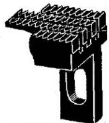
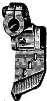
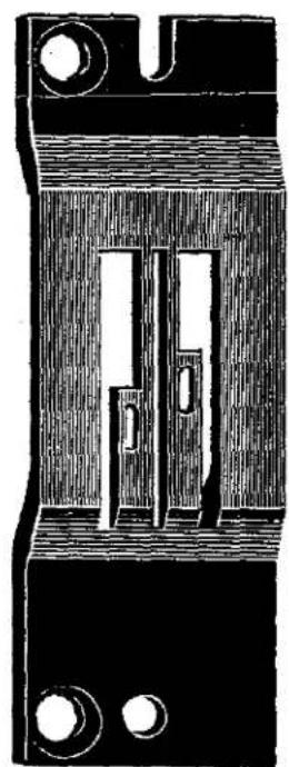
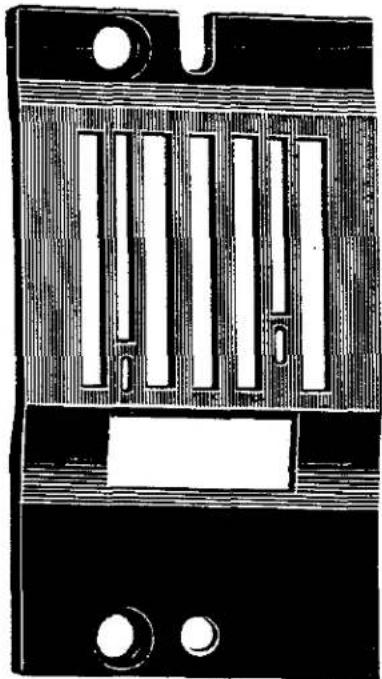
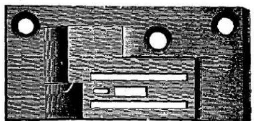
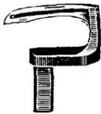
| 51405 B-32 | Feed Dog,for No.32 gauge Style 51400 D.... | 2 |
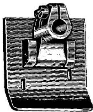
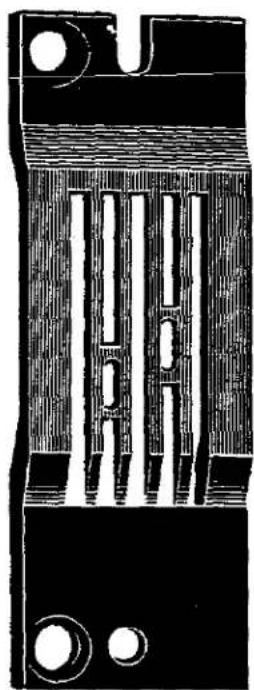
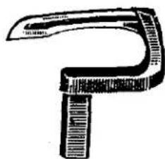
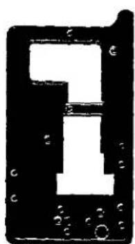
| 51405 B-48 | Feed Dog,for No.48 gauge Styles 51400 B, 51400 D.... | 2 |
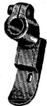
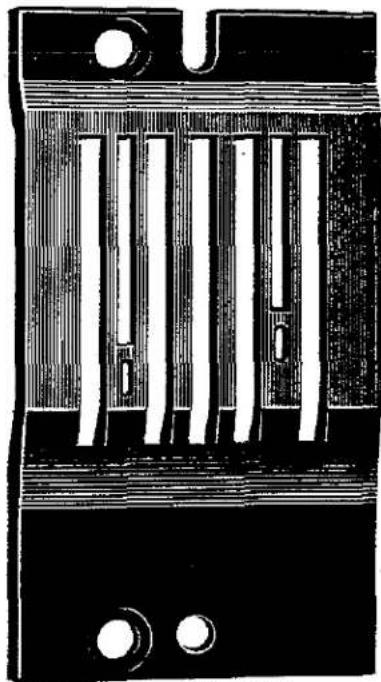
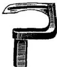
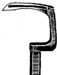
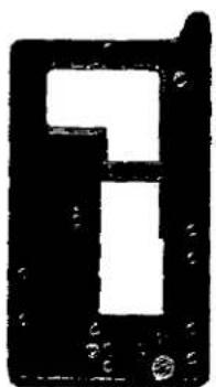
| 51405 C-48 | Feed Dog,for No.48 gauge Style 51400 C.... | 2 |
| Feed Dog Screw No.93 | ||
| 51408-8 | Looper,front,for No.8 gauge Style 51400 A.. | 8 |
| 51408-10 | Looper,front,for No.10 gauge.... | 8 |
| 51408-12 | Looper,front,for No.12 gauge.... | 8 |
| 51408-16 | Looper,front,for No.16 gauge.... | 8 |
| 51408-18 | Looper,front,for No.18 gauge.... | 8 |
| 51408-32 | Looper,front,for No.32 gauge Style 51400 D.. | 8 |
| 51408-48 | Looper,front,for No.48 gauge Styles 51400 B, 51400 C,51400 D.... | 8 |
| 51409 | Looper,for Styles 51200 A,51200 G;also back looper for Style 51400 A,and middle looper for Style 51900 A.... | 8 |
| 51409 B | Looper,back,for Styles 51400 B,51400 C, 51400 D.... | 8 |
| Looper Set Screw No.73 | ||
| 51413 | Looper Rocker,for styles in Class 51400.... | 25 |
| 51417-8 | Needle Bar,for No.8 gauge Style 51400 A.... | 24 |
| 51417-10 | Needle Bar,for No.10 gauge.... | 24 |
| 51417-12 | Needle Bar,for No.12 gauge.... | 24 |
| 51417-16 | Needle Bar,for No.16 gauge.... | 24 |
| 51417-18 | Needle Bar,for No.18 gauge.... | 24 |
| 51417 B | Needle Bar,for Styles 51400 B,51400 C, 51400 D.... | 24 |
| Needle Bar Set Screw No.88 A |
LIST OF PARTS
| Symbol to Order by | The figures in the last column refer only to the plates illustrating the parts and are not to be used in ordering. Refer to pink insert for prices. | Plate No. |
| 51418-16 | Needle Holder, marked "D-16",for Nos.8,10,12, 16 and 18 gauge styles in Class 51400;also for No.16 gauge Style 51500 A | 14 |
| 51418 B-32 | Needle Holder, marked "D-32",for No.32 gauge Style 51400 D | 14 |
| 51418 B-48 | Needle Holder, marked "D-48",for No.48 gauge Styles 51400 B,51400 C,51400 D | 14 |
| Needle Holder Spot Screw No.89 Needle Set Screw No.98 | ||
| 51420-8 | Presser Foot Assembly,for No.8 gauge Style 51400 A;one each Nos.51430 A-8,91, 22799 B,51430 B | 3 |
| 51420-10 | Presser Foot Assembly,for No.10 gauge Style 51400 A;one each Nos.51430 A-10,91, 22799 B,51430 B | 3 |
| 51420-12 | Presser Foot Assembly,for No.12 gauge Style 51400 A;one each Nos.51430 A-12,91, 22799 B,51430 B | 3 |
| 51420-16 | Presser Foot Assembly,for No.16 gauge Style 51400 A;one each Nos.51430 A-16,91, 22799 B,51430 B | 3 |
| 51420-18 | Presser Foot Assembly,for No.18 gauge Style 51400 A;one each Nos.51430 A-18,91, 22799 B,51430 B | 3 |
| 51420 C-32 | Presser Foot Assembly,for No.32 gauge Style 51400 D;one each Nos.51430 C-32,77,91, 22752 B,22799 D,51430 | 3 |
| 51420 C-48 | Presser Foot Assembly,for No.48 gauge Styles 51400 B,51400 C;one each Nos.51430 C-48, 77,91,22752 B,22799 D,51430 | 3 |
| 51422 A | Main Shaft,Crank Section,for styles in Classes 51400,51700;also for Styles 51100 B 51100 C,51200 A,51200 D,51200 E,51200 G, 51900 A | 27 |
| 51423 | "Parallel Take-up",for styles in Classes 51200,51300,51400,51500,51700,51900 | 25 |
| 51424-8 | Throat Plate,for No.8 gauge Style 51400 A | 5 |
| 51424-10 | Throat Plate,for No.10 gauge | 5 |
| 51424-12 | Throat Plate,for No.12 gauge | 5 |
| 51424-16 | Throat Plate,for No.16 gauge | 5 |
| 51424-18 | Throat Plate,for No.18 gauge | 5 |
| 51424 B-32 | Throat Plate,for No.32 gauge Style 51400 D | 6 |
| 51424 B-48 | Throat Plate,for No.48 gauge Styles 51400 B, 51400 D | 6 |
| 51424 C-48 | Throat Plate,for No.48 gauge Style 51400 C Throat Plate Screw No.22570 | 6 |
| 51425 | Needle Guard,for styles in Class 51400 (screw No.22585 B) | 4 |
| 51430 | Presser Foot Shank,for Styles 51400 B, 51400 C,51400 D,51700 C,51700 D | — |
| 51430 A-8 | Presser Foot Bottom,for No.8 gauge Style 51400 A | — |
| 51430 A-10 | Presser Foot Bottom,for No.10 gauge | — |
| 51430 A-12 | Presser Foot Bottom,for No.12 gauge | — |
| 51430 A-16 | Presser Foot Bottom,for No.16 gauge | — |
| 51430 A-18 | Presser Foot Bottom,for No.18 gauge | — |
| 51430 B | Presser Foot Shank,for Style 51400 A | — |
| 51430 C-32 | Presser Foot Bottom,for No.32 gauge Style 51400 D | — |
LIST OF PARTS
| Symbol to Order by | The figures in the last column refer only to the plates illustrating the parts and are not to be used in ordering. Refer to pink insert for prices. | Plate No. |
| 51430 C-48 | Presser Foot Bottom,for No.48 gauge Styles 51400 C,51400 D | — |
| 51443 | Looper Lever Eccentric,for styles in Classes 51400,51700;also Styles 51100 B,51100 C, 51200 A,51200 D,51200 E,51200 G,51900 A (spot screw No.96,set screw No.98).... | 16 |
| 51458 | Needle Lever Thread Eyelet,for styles in Classes 51400,51500,51700 (screw No.22768) | 13 |
| 51458 A | Needle Bar Thread Eyelet,for styles in Classes 51400,51500,51700 (screw No.22768) | 13 |
| 51460 | "Parallel Take-up"Thread Eyelet,front for styles in Classes 51400,51500,51700 (screw No.87 U).... | 13 |
| 51460 A | "Parallel Take-up"Thread Eyelet,rear (screw No.87 U).... | 13 |
| 51461 | "Parallel Take-up"Flange,left,for styles in Classes 51200,51300,51400,51500,51700, 51900 (screw No.22794 B).... | 25 |
| 51461 A | "Parallel Take-up"Flange,right (screw,short No.89,screw,long,No.22764 A).... | 25 |
| 51461 B | "Parallel Take-up" Block.... | 12 |
| 51461 C | "Parallel Take-up" Sleeve.... | 15 |
| 51462 | "Parallel Take-up"Eyelet Stand (screw No.79) | 21 |
| 51462 A | "Parallel Take-up" Eyelet Stud.... | 10 |
| 51462 B | "Parallel Take-up"Eyelet Support (screw No.22560 B).... | 12 |
| 51462 C | "Parallel Take-up"Eyelet Stand Pin.... | 22 |
| 51504 | "Parallel Take-up"Cast-off,for styles in Class 51300 (screw No.22833).... | 17 |
| 51505-18 | Feed Dog,for Nos.16 and 18 gauge Style 51500 A (screw No.93).... | 2 |
| 51508-16 | Looper,front,for No.16 gauge Style 51500 A (screw No.73).... | 8 |
| 51508-18 | Looper,front,for No.18 gauge (screw No.73) . | 8 |
| 51513 | Looper Rocker,for styles in Class 51500 .... | 25 |
| 51517-16 | Needle Bar,for No.16 gauge Style 51500 A (set screw No.88 A).... | 24 |
| 51517 A | Needle Bar,for No.18 gauge Style 51500 A (set screw No.88 A).... | 24 |
| 51520-16 | Presser Foot Assembly,for No.16 gauge Style 51500 A;one each Nos.51530-16,91,22799 C, 35830,51930.... | 3 |
| 51520-18 | Presser Foot Assembly,for No.18 gauge Style 51500 A;one each Nos.51530-18,91,22799 C, 35830,51930.... | 3 |
| 51524-16 | Throat Plate,for No.16 gauge Style 51500 A (screw No.22570).... | 5 |
| 51524-18 | Throat Plate,for No.18 gauge (screw No.22570) | 5 |
| 51525 | Needle Guard,for styles in Class 51500 (screw No.22585 B).... | 4 |
| 51530-16 | Presser Foot Bottom,for No.16 gauge Style 51500 A.... | — |
| 51530-18 | Presser Foot Bottom,for No.18 gauge.... | — |
| 51701 | Cloth Plate,for styles in Class 51700 (screw No.80).... | 32 |
| 51705-56 | Feed Dog,for No.56 gauge Style 51700 C.... | 2 |
| 51705-64 | Feed Dog,for No.64 gauge Style 51700 C.... | 2 |
| 51705 D-64 | Feed Dog,for No.64 gauge Style 51700 D.... | 2 |
| Feed Dog Screw No.93 |
LIST OF PARTS
| Symbol to Order by | The figures in the last column refer only to the plates illustrating the parts and are not to be used in ordering. Refer to pink insert for prices. | Plate No. |
| 51708 | Looper,right,for styles in Class 51700(screw No.73) | 8 |
| 51709 | Looper,left,for styles in Class 51700(screw No.73) | 8 |
| 51713 | Looper Rocker,for Styles in Class 51700 | 25 |
| 51717 | Needle Bar, for styles in Class 51700(set screw No.88 A) | 24 |
| 51720-56 | Presser Foot Assembly,for No.56 gauge Style51700 C;one each Nos.51730-56,77,91,22752 B,22799 D,51430,51730 A-56 and twoNo.91 A | 3 |
| 51720-64 | Presser Foot Assembly,for No.64 gauge Style51700 C;one each Nos.51730-64,77,91,22752 B,22799 D,51430,51730 A-64 and twoNo.91 A | 3 |
| 51720 D-64 | Presser Foot Assembly,for No.64 gauge Style51700 D;one each Nos.51730 D-64,77,91,22752 B,22799 D,51430 | 3 |
| 51724-56 | Throat Plate,for No.56 gauge Style 51700 C | 6 |
| 51724-64 | Throat Plate,for No.64 gauge Style 51700 C | 6 |
| 51724 D-64 | Throat Plate,for No.64 gauge Style 51700 D | 6 |
| 51725 | Needle Guard,for styles in Class 51700(screw No.22585 B) | 4 |
| 51730-56 | Presser Foot Bottom,for No.56 gauge Style51700 C | — |
| 51730-64 | Presser Foot Bottom,for No.64 gauge | — |
| 51730 A-56 | Presser Foot Flexible Toe,for No.56 gaugeStyle 51700 C (screw No.91 A) | 4 |
| 51730 A-64 | Presser Foot Flexible Toe,for No.64 gaugeStyle 51700 C (screw No.91 A) | 4 |
| 51730 D-64 | Presser Foot Bottom,for No.64 gauge Style51700 D | — |
| ‡ 51741 | Looper Connecting Rod Ball Joint Assembly,left,for styles in Class 51700 (screwNo.97 A) | 16 |
| ‡ 51741 B | Looper Connecting Rod Ball Joint Assembly,right, for styles in Classes 51100,51700(screw No.97 A) | 16 |
| ‡ 51743 A | Looper Lever Connection Guard,for styles inClass 51700 (screw No.94) | 28 |
| 51744 | Looper Rocker Frame,for styles in Class51700 (spot screw No.96, set screw No.98). | 18 |
| 51745 | Looper Rocker Cone Stud | 17 |
| 51751 | Presser Bar Guide,for styles in Classes51100,51700 (screw No.531) | 17 |
| 51758 | Frame Needle Thread Eyelet,for styles inClasses 51100,51700 (screw No.94,adapterscrew No.22840) | 14 |
| 51758 A | Frame Needle Thread Guide,for styles inClass 51700 (screw No.22730) | 14 |
| 51759 | Frame Looper Thread Eyelet,for styles inClass 51700 (screw No.93) | 13 |
| 51770-56 | Looper Rocker Link,for No.56 gauge styles inClass 51700 (screw No.22757) | 16 |
| 51770-64 | Looper Rocker Link,for No.64 gauge (screwNo.22757) | 16 |
| 51771 | Looper Rocker Link Bushing | 15 |
LIST OF PARTS
| Symbol to Order by | The figures in the last column refer only to the plates illustrating the parts and are not to be used in ordering. Refer to pink insert for prices. | Plate No. |
| 51772-56 | Looper Rocker Spacing Plate,for No.56 gauge styles in Class 51700 | 25 |
| 51772-64 | Looper Rocker Spacing Plate,for No.64 gauge | 25 |
| 51773 | Looper Rocker Frame Sleeve,for styles in Class 51700 (screw No.88 B) | 15 |
| 51905-5 | Feed Dog,for No.5 gauge Style 51900 A | 2 |
| 51905-7 | Feed Dog,for Nos.6 and 7 gauge Style 51900 A,No.7 gauge Style 51900 B | 2 |
| 51905 B-9 | Feed Dog,for Nos. 8 and 9 gauge Style 51900 B | 2 |
| Feed Dog Screw No.93 | ||
| 51908-5 | Looper,front,for No.5 gauge Style 51900 A | 8 |
| 51908-6 | Looper,front,for No.6 gauge Style 51900 A | 8 |
| 51908-7 | Looper,front,for No.7 gauge Style 51900 A | 8 |
| 51908 A-7 | Looper,front,for No.7 gauge Style 51900 B | 8 |
| 51908 A-8 | Looper,front,for No.8 gauge Style 51900 B | 8 |
| 51908 A-9 | Looper,front,for No.9 gauge Style 51900 B | 8 |
| 51909-5 | Looper,back,for No.5 gauge Style 51900 A | 8 |
| 51909-6 | Looper,back,for No.6 gauge Style 51900 A | 8 |
| 51909-7 | Looper,back,for No.7 gauge Style 51900 A | 8 |
| 51909 A-7 | Looper,back,for No.7 gauge Style 51900 B | 8 |
| 51909 A-8 | Looper,back,for No.8 gauge Style 51900 B | 8 |
| 51909 A-9 | Looper,back,for No.9 gauge Style 51900 B | 8 |
| 51909 B | Looper,for Style 51200 B;also back looper for Style 51500 A and middle looper for Style 51900 B | 8 |
| Looper Set Screw No.73 | ||
| 51913 | Looper Rocker,for styles in Class 51900 | 25 |
| 51917-5 | Needle Bar,for Nos.5,6 and 7 gauge styles in Class 51900 (screw No.88 A) | 24 |
| 51917-9 | Needle Bar,for Nos.8 and 9 gauge styles in Class 51900 (screw No.88 A) | 24 |
| 51918-5 | Needle Holder,marked "E-5",for No.5 gauge Style 51900 A | 14 |
| 51918-6 | Needle Holder,marked "E-6",for No.6 gauge Style 51900 A | 14 |
| 51918-7 | Needle Holder,marked "E-7",for No.7 gauge styles in Class 51900 | 14 |
| Needle Holder Spot Screw No.89 | ||
| Needle Set Screw,outer,No.98 | ||
| Needle Set Screw,middle,No.22752 A | ||
| 51920-5 | Presser Foot Assembly,for No.5 gauge Style 51900 A;one each Nos.51930 B-5,91, 12935 A,22799 E,51930 A | 3 |
| 51920-6 | Presser Foot Assembly,for No.6 gauge Style 51900 A;one each Nos.51930 B-6,91, 12935 A,22799 E, 51930 A | 3 |
| 51920-7 | Presser Foot Assembly,for No.7 gauge Styles 51900 A,51900 B;one each Nos. 51930 B-7,91,12935 A,22799 E,51930 A | 3 |
| 51924-5 | Throat Plate,for No.5 gauge Style 51900 A | 7 |
| 51924-6 | Throat Plate,for No.6 gauge Style 51900 A | 7 |
| 51924-7 | Throat Plate,for No.7 gauge Styles 51900 A, 51900 B | 7 |
| 51924 B-8 | Throat Plate,for No.8 gauge Style 51900 B | 7 |
| 51924 B-9 | Throat Plate,for No.9 gauge Style 51900 B | 7 |
| 51925 | Throat Plate Screw No.22570 Needle Guard,for styles in Class 51900 (screw No.22585 B) | 4 |
LIST OF PARTS
| Symbol to Order by | The figures in the last column refer only to the plates illustrating the parts and are not to be used in ordering. Refer to pink insert for prices. | Plate No. |
| 51930 | Presser Foot Tilting Spring,for Styles 51900 A,51900 B | 11 |
| 51930 A | Presser Foot Shank,for Style 51900 A | — |
| 51930 B-5 | Presser Foot Bottom,for No.5 gauge Style 51900 A | — |
| 51930 B-6 | Presser Foot Bottom,for No.6 gauge | — |
| 51930 B-7 | Presser Foot Bottom,for No.7 gauge | — |
| 51958 | Needle Lever Thread Eyelet,for styles in Class 51900 (screw No.22768) | 13 |
| 51958 A | Needle Bar Thread Eyelet,for styles in Class 51900 (screw No.22768) | 13 |
| 51959 | Looper Thread Nipper Support,for styles in Classes 51200,51300,51400,51500,51900 (screw No.93 A) | 14 |
| 51959 B | Looper Thread Nipper Disk | 14 |
| 51959 C | Looper Thread Nipper Spring | 11 |
| 51959 D | Looper Thread Nipper Nut | 11 |
| 51959 E | Looper Thread Nipper Stud Spacing Collar, for styles in Classes 51200,51300,51400, 51500 | 15 |
| 51960 | "Parallel Take-up" Thread Eyelet,front,for styles in Class 51900 (screw No.87 U) | 13 |
| 51960 A | "Parallel Take-up" Thread Eyelet,rear,for styles in Class 51900 (screw No.87 U) | 13 |
Union Special Corporation maintains sales and service facilities throughout the world. These offices will aid you in the selection of the right sewing equipment for your particular operation. Union Special Corporation representatives and service technicians are factory trained and are able to serve your needs promptly and efficiently. Whatever your location, there is a qualified representative to serve you.
Corporate
Office:
One Union Special Plaza
Huntley, IL 60142
Phone: 847·669·5101
Fax: 847-669-4454
European Distribution Center:
Union Special GmbH
Raiffeisenstrasse 3
D-71696 Möglingen, Germany
Tel: 49-07141-247-0
Fax: 49·07141·247·100
Brussels, Belgium
Charlotte, N.C.
El Paso, TX
Hong Kong, China
Huntley, IL
Leicester, England
Lille, France
Miami, FL
Milan, Italy
Möglingen, Germany
Montreal, Quebec
Osaka, Japan
Santa Fe Springs, CA
Other Representatives throughout all parts of the world.

Finest Quality
Union Special INDUSTRIAL SEWING EQUIPMENT