CS122H21 - Sewing machine Union Special - Free user manual and instructions
Find the device manual for free CS122H21 Union Special in PDF.

User questions about CS122H21 Union Special
0 question about this device. Answer the ones you know or ask your own.
Ask a new question about this device
Download the instructions for your Sewing machine in PDF format for free! Find your manual CS122H21 - Union Special and take your electronic device back in hand. On this page are published all the documents necessary for the use of your device. CS122H21 by Union Special.
USER MANUAL CS122H21 Union Special
ILLUSTRATED PARTS MANUAL
text_image
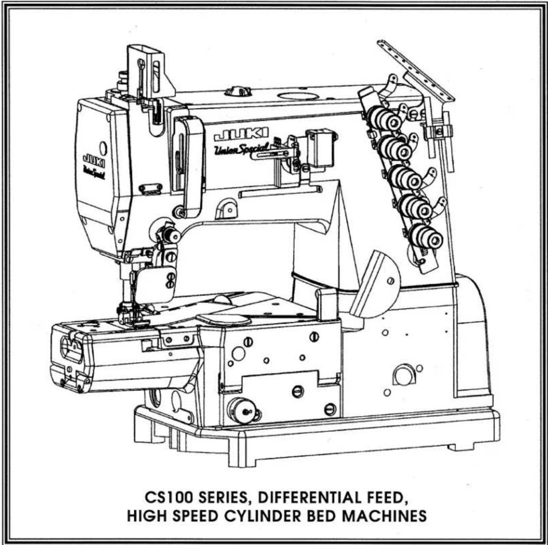
CS100 SERIES, DIFFERENTIAL FEED, HIGH SPEED CYLINDER BED MACHINESMANUAL NO. PT9801
FOR STYLES
CS122E11 CS122H01 CS122H21 CS122K01
CS132E11 CS132H01 CS132H21 CS132K01
CS125E61 CS125H11 CS125H31 CS122K02
CS125E62 CS135H11 CS135H31 CS132K02
CS135E61 CS125H12 CS125H32
CS135E62 CS135H12 CS135H32
USE IN CONJUNCTION WITH MACHINE SERIAL NUMBER PREFIX (BG) AND LATER
REV 6-14-00
SecondEdition Copyright 2000
By
Union Special Corporation Rights Reserved In All Countries
Printed in U.S.A. April 2000
PREFACE
This parts manual has been prepared to assist you in locating individual parts or assemblies on CS100 Series machines.
IDENTIFICATION OF MACHINES
Each UNION SPECIAL machine is identified by a style number, which is stamped into the style plate affixed to the middle of the machine under the tension assembly. The serial number is stamped into the serial number plate affixed to the right rear base of the machine.
CONTENTS
PREFACE 2
IDENTIFICATION OF MACHINES 2
STYLES OF MACHINES 4
STYLES OF MACHINES (CONT.) 5
ILLUSTRATIONS 5
IDENTIFYING PARTS 5
NEEDLES 5
SAFETY RULES 6
BUSHINGS 9
NEEDLE BAR....11
UPPER MAIN SHAFT 13
SPREADER 15
THREAD GUIDE 17
PRESSER FOOT LIFT 21
COVERS, UPPER ARM 23
LOWER MAIN SHAFT 25
LUBRICATION, OIL TUBING & OIL PUMP 27
LOOPER DRIVE 29
LOOPER THREAD TAKE -UP & NEEDLE GUARD 31
FEED DRIVE MECHANISM 33
FEED DRIVE MECHANISM 35
COVERS FOR CS122E11, CS132E11, CS125E61, CS125E62, CS135E61, CS135E62.... 37
COVERS LOWER BED- FRONT 39
COVERS LOWER BED- MIDDLE 41
COVERS LOWER BED - REAR 43
SEWING PARTS FOR CS122E11, CS125E61, CS125E62, CS132E11, CS135E61, CS135E62....45
SEWING PARTS FOR CS122H01, CS132H01 47
SEWING PARTS FOR CS125H11, CS125H12, CS135H11, CS135H12....49
SEWING CHART FOR CS125H11, CS135H11 50
SEWING CHART FOR CS125H12, CS135H12 51
SEWING PARTS FOR CS122H21, CS132H21 53
SEWING PARTS FOR CS122K01, CS122K02, CS132K01, CS132K02 55
ACCESSORIES 57
TAPE GUIDE, HOLD DOWN DEVICE FOR CS122E11, CS125E61, CS125E62, CS132E11, CS135E61, CS135E62....59
UNDER TRIMMER ASSEMBLY FOR CS122E11, CS125E61, CS125E62, CS132E11, CS135E61, CS135E62....61
PULLER LIFTER ASSEMBLY FOR CS125E61, CS125E62, CS125H11, CS125H12, CS135E61, CS13562, CS135H11, CS135H12 .... 63
PULLER DRIVE ASSEMBLY FOR CS125E61, CS125E62, CS125H11, CS125H12, CS135E61, CS13562, CS135H11, CS135H12 .... 65
LOWER ROLLER ASSEMBLY FOR CS125E61, CS125E62, CS125H11, CS125H12, CS135E61, CS135E62, CS135H11, CS135H12 .... 67
UPPER ROLLER ASSEMBLY FOR CS125E61, CS125E62, CS125H11, CS125H12, CS135E61, CS135E62, CS135H11, CS135H12 .... 69
FABRIC TRIMMER ASSEMBLY FOR CS122H21, CS132H21 71
NEEDLE DIPPER (EXTRA SEND CHARGE) 73
NUMERICAL INDEX OF PARTS 74
NUMERICAL INDEX OF PARTS 75
NUMERICAL INDEX OF PARTS 76
NUMERICAL INDEX OF PARTS 77
NOTES 78
NOTES 79
STYLES OF MACHINES
Precision two or three needle cylinder bed machines, with top and bottom coverstitch or bottom coverstitch only. Rotary mainshafts for smoother, quieter and faster operations. Equipped with quick change for main and differential feed. Independently driven rear needle guard, no adjustment necessary when changing stitch length. Adjustable looper avoid eccentric to adapt the looper avoid motion and the elliptic path of looper to the required needle size and type of sewing threads. Recommended needle 121GJS, needle range sizes 055/022 - 090/036.
| CS122E11 | ELASTIC. Two or three needle, bottom coverstitch, right hand fabric undertrimmer. - Typical Application - For attaching preclosed elastic while trimming the edge of the fabric. Seam Specification for two needle 406 LSA-1, for three needle 407 LSA-1. Standard gauge for two needle 40, (5/32", 4.0mm), 48, (3/16", 4.8mm), for three needle 56, (7/32", 5.6mm), 64, (1/4", 6.4mm). Maximum recommended speed, depending on application is up to 5500 R.P.M.. |
| CS132E11 | ELASTIC. Same as Style CS122E11 except top coverstitch, Seam Specification for two needle 602 LSA-1, for three needle 605 LSA-1. |
| CS125E61 | ELASTIC. Same as CS122E11 except equipped with rear roller. |
| CS125E62 | ELASTIC. Same as CS122E11 except equipped with rear roller. |
| CS135E61 | ELASTIC. Same as CS132E11 except equipped with rear roller. |
| CS135E62 | ELASTIC. Same as CS132E11 except equipped with rear roller. |
| CS122H01 | HEMMING. Two or three needle, bottom coverstitch. - Typical Application - For circular hemming operations on light, medium and heavy weight knit fabrics. Seam Specifications for two needle 406 EFa-1(inv.), for three needle 407 EFa-1 (inv.). Standard gauges for two needle 40, (5/32", 4.0mm), 48, (3/16", 4.8mm), for three needle 56, (7/32", 5.6mm), 64, (1/4", 6.4mm). Recommended speed, depending on application is up to 6500 R.P.M.. |
| CS132H01 | HEMMING. Same as Style CS122H01 except, top and bottom coverstitch. Seam Specification for two needle 602 EFa-1 (inv.), for three needle 605EFa-1 (inv.). |
| CS125H11 | HEMMING. Two or three needle, rear puller. - Typical Application - For hemming applications. Seam Specifications for two needle 406 EFa-1 (inv.), for three needle 407 EFa-1 (inv.). Standard gauges for two needle 40, (5/32", 4.0mm), 48, (3/16", 4.8mm), for three needle 56, (7/32", 5.6mm), 64, (1/4", 6.4mm). Maximum recommended speed, depending on application is up to 6000 R.P.M.. |
| CS135H11 | HEMMING. Same as Style CS125H11 except top and bottom coverstitch. Seam Specification for two needle 602 EFa-1 (inv.), for three needle 605 EFa-1 (inv.). |
| CS125H12 | HEMMING. Same as CS125H11 except equipped with rubber roller on rear puller. |
| CS135H12 | HEMMING. Same as CS135H11 except equipped with rubber roller on rear puller. |
| CS122H21 | HEMMING. Two or three needle, left hand fabric undertrimmer, bottom coverstitch. - Typical Application - For general hemming of circular openings while trimming the edge of the hem. Seam Specifications for two needle 406 EFa-1 (inv.), for three needle 407 EFa-1 (inv.). Standard gauges for two needle 40, (5/32", 4.0mm), 48, (3/16", 4.8mm), for three needle 56, (7/32", 5.6mm), 64, (1/4", 6,4mm). Maximum recommended speed, depending on application is up to 5500 R.P.M.. |
| CS132H21 | HEMMING. Same as Style CS122H21 except top and bottom coverstitch. Seam Specification for two needle 602 EFa-1 (inv.), for three needle 605 EFa-1 (inv.). |
| CS122K01 | COVERSEAM. Two needle, bottom coverstitch. - Typical Application - for the second operation to bottom coverstitch overedge seams of circular openings such as shoulder, neck, and waist of light weight knit garments. Seam Specification 406 SSh-2. Standard gauges 48, (3/16", 4.8mm), 56, (7/32", 5.6mm), 64, (1/4", 6.4mm). Recommended speed, depending on application is up to 6500 R.P.M.. |
| CS122K02 | COVERSEAM. Same as Style CS122K01 except Adjustable, split seam guide, for medium to heavy weight knit garments. Standard gauges 56, (7/32", 5.6mm), 64, (1/4", 6.4mm). |
STYLES OF MACHINES (CONT.)
CS132K01 COVERSEAM. Same as Style CS122K01 except top and bottom coverstitch. Seam Specifications 602 SSh-2. - Typical Application - for light to medium fabrics.
CS132K02 COVERSEAM. Same as Style CS122K02 except Seam Specification 602 SSh-2.
ILLUSTRATIONS
This manual has been arranged to simplify ordering repair parts. Exploded views of various sections of the mechanism are shown so that the parts may be seen in their actual position in the machine. On the page opposite the illustration will be found a listing of the parts with their part numbers, description and the number of pieces required in the particular view being shown.
Numbers in the first column are reference numbers only, and merely indicate the position of the part in the illustration. The reference number should never be used in ordering parts. Always use the part number listed in the second column.
Component parts of sub-assemblies which can be furnished for repairs are indicated by indenting their descriptions under the description of the main sub-assembly. As an example refer to the following text.
- 50366B Needle Thread Strike-Off Assembly 1
- 50358V Needle Thread Strike-Off 1
- 50370F Thread Strike-Off Component ....1
- SS7060310SP Screw, for plate strike-off 1
When a part is common to all machines covered in this manual, no specific usage will be mentioned in the description. However, when the parts for the various machines are not the same, the specific usage will be mentioned in the description and, if necessary, the difference will be shown in the illustration.
*NOTE: Ref. No. showing no Part No. is for location only. Part is not for sale separately.
A numerical index of all the parts shown in this manual is located at the back. This will facilitate locating the illustration and description when only a part number is known.
IDENTIFYING PARTS
Where construction permits, each part is stamped with its part number. On some of the smaller parts and on those where construction does not permit, an identification letter is stamped in to distinguish the part from similar ones.
PLEASE NOTE: Part numbers represent the same part, regardless of which manual they appear. On all orders please include part number, name and style of machine for which the part was ordered.
For optimum performance use only genuine Union Special replacement parts.
NEEDLES
Each needle has both a type and size number. The type number denotes the kind of shank, point, length, groove, finish and other details. The size number, stamped on the needle shank, denotes the largest diameter of the blade measured between the shank and the eye. Collectively, the type number and size number represent the complete symbol which is given on the label of all needles packed and sold by Union Special.
TYPE
DESCRIPTION
121 GJS Short, double groove, struck groove, ball eye, spotted, ball point, chromium plated- Sizes available 055/022, 065/025, 070/027, 075/029, 080/032, 090/036.
When changing the needle, make sure it is fully inserted in the holder before the screw is tightened.
When ordering needles, please use the complete type and size numbers as printed on the package to ensure prompt and accurate processing of your order. A complete order should read as follows: "100 needles, type 121 GJS, size 075/029".
SAFETY RULES
- Before putting the machines described in this manual into service, carefully read the instructions. The starting of each machine is only permitted after taking notice of the instructions and by qualified operators.
IMPORTANT! Before putting the machine into service, also read the safety rules and instruction from the motor supplier.
-
Observe the national safety rules valid for your country.
-
The sewing machines described in this instruction manual are prohibited from being put into service until it has been ascertained that the sewing units which these sewing machines will be built into, have conformed with the EC Council Directives (89/392/EEC, Annex II B).
Each machine is only allowed to be used as foreseen. The foreseen use of the particular machine is described in paragraph "STYLES OF MACHINES" of this instruction manual. Another use, going beyond the description, is not as foreseen.
-
All safety devices must be in position when the machine is ready for work or in operation. Operation of the machine without the appertaining safety devices is prohibited.
-
Wear safety glasses.
-
In case of machine conversions and changes all valid safety rules must be considered. Conversions and changes are made at your own risk.
-
The warning hints in the instructions are marked with one of these two symbols:

- When doing the following the machine has to be disconnected from the power supply by turning off the main switch or by pulling out the main plug:
8.1 When threading needle(s), looper, spreader etc.
8.2 When replacing any parts such as needle(s), presser foot, throat plate, looper, spreader, feed dog, needle guard, folder, fabric guide etc.
8.3 When leaving the workplace and when the workplace is unattended.
8.4 When doing maintenance work.
8.5 When using clutch motors without actuation lock, wait until the motor is stopped totally.
-
Maintenance, repair and conversion work (see item 8) must be done only by trained technicians or special skilled personnel under consideration of the instructions.
-
Any work on the electrical equipment must be done by an electrician or under direction and supervision of special skilled personnel.
-
Work on parts and equipment under electrical power is not permitted. Permissible exceptions are described in the applicable sections of standard sheet DIN VDE 0105.
-
Before doing maintenance and repair work on the pneumatic equipment, the machine has to be disconnected from the compressed air supply. In case of existing residual air pressure after disconnecting from compressed air supply (i.e. pneumatic equipment with air tank), the pressure has to be removed by bleeding.
CS100 SERIES
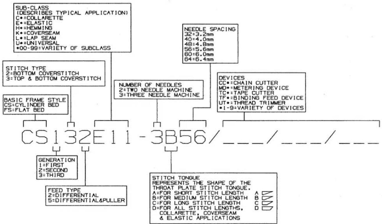
BUILDING BLOCK STYLE
DESIGNATION SYSTEM
flowchart
graph TD
    A["SUB-CLASS (DESCRIBES TYPICAL APPLICATION)<br>C:=COLLARETTE<br>E:=ELASTIC<br>H:=HEMMING<br>K:=COVERSEAM<br>L:=LAP SEAM<br>U:=UNIVERSAL<br>•00-99=VARIETY OF SUBCLASS"] --> B["STITCH TYPE<br>2=BOTTOM COVERSTITCH<br>3=TOP & BOTTOM COVERSTITCH"]
    A --> C["NEDLE SPACING<br>32=3.2mm<br>40=4.0mm<br>48=4.8mm<br>56=5.6mm<br>60=6.0mm<br>64=6.4mm"]
    B --> D["BASIC FRAME STYLE<br>CS=CYLINDER BED<br>FS=FLAT BED"]
    D --> E["CS132E11-3B56/____/____/____/____"]
    B --> F["NUMBER OF NEEDLES<br>2=TWO NEEDLE MACHINE<br>3=THREE NEEDLE MACHINE"]
    F --> G["DEVICES<br>CC:=CHAIN CUTTER<br>MD:=METERING DEVICE<br>TC:=TAPE CUTTER<br>TF:=BINDING FEED DEVICE<br>UT:=THREAD TRIMMER<br>•1-9=VARIETY OF DEVICES"]
    E --> H["GENERATION<br>1=FIRST<br>2=SECOND<br>3=THIRD"]
    E --> I["FEED TYPE<br>2=DIFFERENTIAL<br>5=DIFFERENTIAL&PULLER"]
    I --> J["STITCH TONGUE<br>REPRESENTS THE SHAPE OF THE<br>THROAT PLATE STITCH TONGUE.<br>A:FOR SHORT STITCH LENGTH A □<br>B:FOR MEDIUM STITCH LENGTH B □<br>C:FOR LONG STITCH LENGTH C □<br>D:FOR ALL STITCH LENGTHS, D □<br>COLLARETTE, COVERSEAM & ELASTIC APPLICATIONS"]

text_image
Loctite Union Special No. CE27BUSHINGS
Ref.
No. Part No.
Description
Amt.
Req.
- 50347E Bushing, for spreader, rear .... 1
- 50347F Bushing, for spreader, front 1
- 50354J Bushing, for needle bar, upper 1
- 50344BU Bushing, for upper main shaft, front 1
- 50332U Pin 1
- 50347L Bushing, for spreader drive 1
- 50354H Bushing, for needle bar, lower 1
- 50330CZ Bushing, for presser bar 1
- 99352 Stop Screw 2
Stop 1 - 22894BD Screw, for cast-off plate stud 1
- 96841 Pin.... 1
- 34390 Bushing, for main shaft, left 1
- 50393EZ Oil Seal 1
- 34336C Bushing, for feed rocker, left 1
- 34336D Bushing, for feed lifter shaft, left 1
- 34336B Bushing, for feed rocker shaft, right.... 1
- 34336E Bushing, for feed lifter shaft, right 1
- 22565C Set Screw 1
- 50344BP Bushing, for main shaft, middle 1
- 34394A Oil Tube 1
- 50393KW Oil Tube 1
- 22894AD Screw 1
- 999-211B "O" Ring 1
- 50344BL Bushing, for cast-off plate bracket 1
- PS0400142KH Pin 1
- 50381E Bushing, for lifter lever, back 1
- 50392AB Bushing, for tension release 1
- 22571F Plug Screw 2
- 34394B Oil Tube 1
- 50393GF Oil Sight Gauge 1
- 34342G Bushing, for looper drive shaft, front 1
- 50344BN Differential Feed Adjusting Assembly 1
Differential Feed Adjusting Shaft 1
"O"Ring 1
Differential Adjusting Bushing 1 - 34342F Bushing, for looper drive shaft rear 1
- 22829 Screw 1
- 50344AV Bushing 1
- SS8660612TP Screw 1
- 999-211 "O" Ring 1
text_image
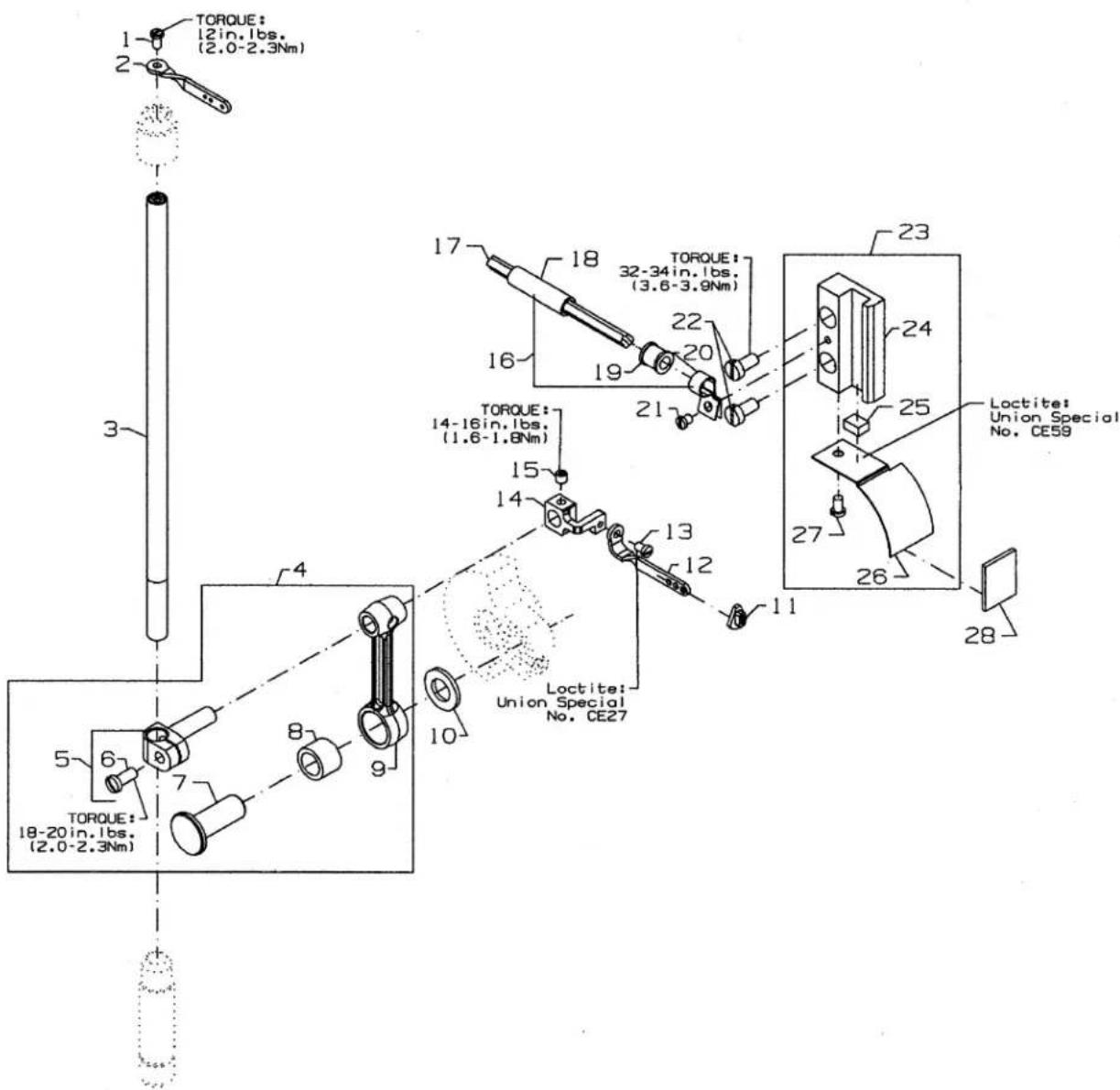
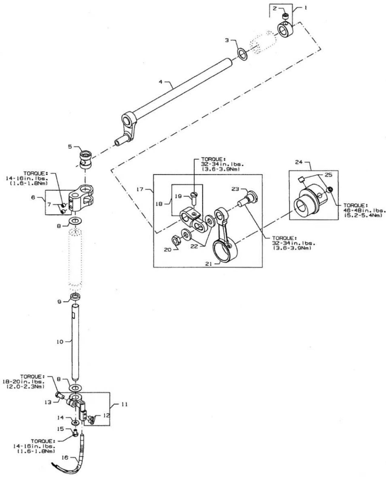
TORQUE: 12in.1bs. (2.0-2.3Nm) TORQUE: 18-20in.1bs. (2.0-2.3Nm) 1 2 3 4 5 6 7 8 9 10 11 12 13 14 15 16 17 18 19 20 21 22 23 24 25 26 27 28 Loctite: Union Special No. CE59 Loctite: Union Special No. CE27NEEDLE BAR
Ref.
No. Part No.
Description
Amt.
Req.
- SS4080620TP Screw 1
- 50323P Needle Bar Eyelet 1
- 50317B Needle Bar 1
- 50345W Connecting Rod Assembly 1
- 50355AM Needle Bar Clamp 1
- SS7111120TP Screw 1
- 50352 Pivot Pin 1
- 661-259B Needle Bearing Cage 1
- 50355AN Connecting Rod 1
- 50351A Washer 1
- 50393JP Eyelet Seal 1
- 50358X Needle Thread Eyelet 1
- SS7080520SP Screw 1
- CE27 Loctite Adhesive, (not shown), for screw
- 50354F Slide Block 1
- CE63 Three Bond Adhesive, (not shown), for slide block....
- SS8110422TP Screw 1
- 29476TC Oil Tube Assembly 1
- CQ25220000 Wick 1
- 50393JY Oil Tube 1
- 50393JZ Oil Tube 1
- 50393JW Hose Clamp 1
- SS6090440SP Screw, for support bracket 1
- SS6121010SP Screw 2
- 29476TH Slide Block Guide Assembly 1
- 50354G Slide Block Guide 1
- 50393HS Sponge 1
- CE59 Loctite Adhesive, (not shown), for sponge
- 50394AF Slide Block Guide Cover 1
- SS6090620SP Screw 1
- 666-329 Felt 1
text_image
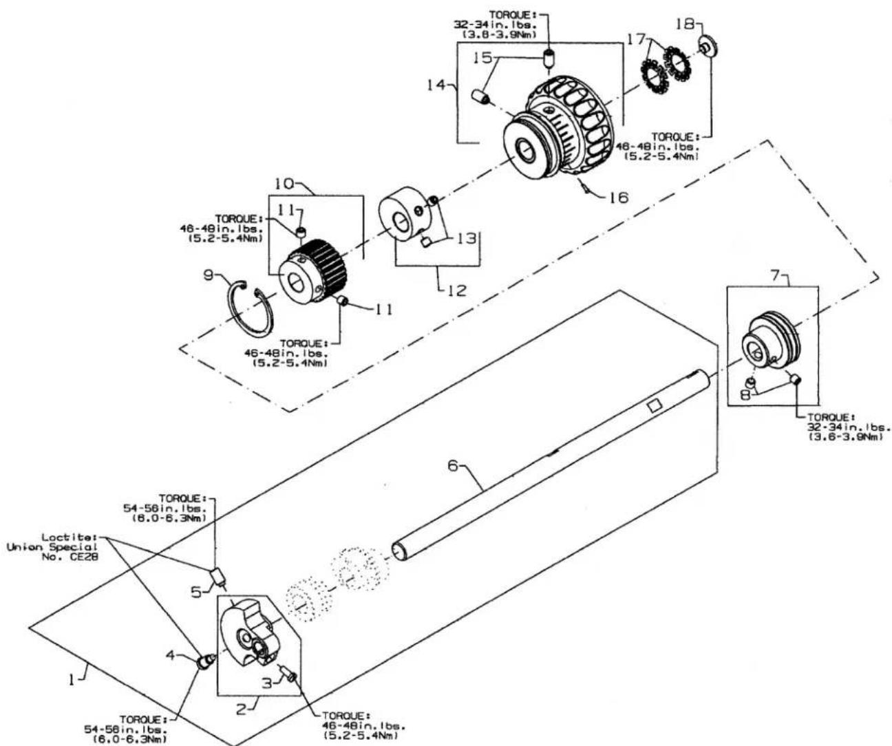
TORQUE: 32-34in.1bs. (3.8-3.9Nm) TORQUE: 46-48in.1bs. (5.2-5.4Nm) TORQUE: 10 11 12 13 14 15 16 17 18 TORQUE: 46-48in.1bs. (5.2-5.4Nm) TORQUE: 46-48in.1bs. (5.2-5.4Nm) TORQUE: 54-58in.1bs. (8.0-6.3Nm) TORQUE: 54-58in.1bs. (6.0-6.3Nm) Lactite: Union Special No. CE28 1 2 3 4 5 6 7 TORQUE: 32-34in.1bs. (3.6-3.9Nm)UPPER MAIN SHAFT
Ref.
No. Part No.
Description
Amt.
Req.
-
50322BB Upper Main Shaft Assembly 1
-
50391 Counter Weight 1
-
SS7111120TP Screw, for counter weight 1
-
SS7681410TP Screw, for counter weight 1
-
SS8681412TP Screw, for counter weight 1
-
50322AF Upper Main Shaft 1
-
50335BD Bearing Adapter Assembly 1
-
SS8660612TP Screw, for bearing adapter 2
-
661-262 Retaining Ring 1
-
50342AY Sprocket, for upper main shaft 1
-
SS8661012TP Set Screw, for sprocket 2
-
50391A Counterweight 1
-
SS8660612TP Screw 2
-
50321M Handwheel.... 1
-
SS8681412TP Set Screw, for handwheel 2
-
660-1043 Tack Pin, for hand wheel 1
-
661-261 Load Ring, for lower main shaft 2
-
SS7660520SP Screw, for handwheel preload 1
text_image
TORQUE: 14-16in. Ibs. (1.8-1.8Nm) TORQUE: 32-34in. Ibs. (3.6-3.9Nm) TORQUE: 46-48in. Ibs. (15.2-5.4Nm) TORQUE: 32-34in. Ibs. (3.6-3.9Nm) TORQUE: 18-20in. Ibs. (2.0-2.3Nm) TORQUE: 14-16in. Ibs. (1.6-1.8Nm)SPREADER
Ref.
No. Part No.
Description
Amt.
Req.
- 50335AW Collar, for spreader shaft 1
- SS8660512TP SetScrew 1
- 96162B Washer 1
- 50360B Crankshaft, for spreader assembly 1
- 50347J Pin, for spreader rocker....1
- 50347C Lever, for spreader holder shaft 1
Screw 2 - 61351C Washer 2
- 660-739 Oil Seal 1
- 50347G Shaft, for spreader, vertical 1
- 50346A Spreader Holder 1
Screw 2
Screw 1 - 53678N Washer....1
- SS9090640SP Hex Screw, for vertical shaft 1
- 50360H Spreader 1
- 29126FW Spreader Crank Rod Assembly 1
- 50360G Spreader Shaft Driving Arm 1
Screw 1 - NS6680410SP Hex Nut, for spreader drive 1
- 50360F Connecting Rod, for spreader drive 1
Collar, for spreader driving arm 2 - SD1000801SH Stud 1
- 50360 Eccentric, for spreader drive 1
- SS8660612TP Screw 2

text_image
Technical diagram of a mechanical assembly with numbered components and labeled parts in ChineseTHREAD GUIDE
| Ref. | Amt. | ||
| No. | Part No. | Description | Req. |
-
SS7120640SP Screw, for lead-in eyelet 2
-
50392AU Thread Eyelet Assembly 1
-
SS7090910TP Screw, for tube bracket 1
-
WS0510002KP Washer 1
-
50366 Thread Eyelet Tube 2
-
50366A Thread Eyelet Tube Bracket 1
-
50392S Lead-in Tension Eyelet 1
-
SS4120615SP Screw, for spreader thread guide 2
-
50363CK Needle Thread Guide & Lubricator Assembly 1
-
50358U Thread Guide, for spreader 1
-
SS7110410SP Screw, for needle thread guide 1
-
50393HH Silicone Thread Lubricator 1
-
WS0371026SD Washer 2
-
50366J Needle Thread Guide 1
-
SS7080510TP Screw, for holder eyelet 1
-
SS4090815SP Screw, for silicone tank 2
-
50358W Holder, for needle thread eyelet 1
-
SS8080410TP Screw 3
-
36271A Adjusting Needle Thread Eyelet 3
-
SS7120710SP Screw, for strike-off 1
-
50366B Needle Thread Strike-Off Assembly 1
-
SS7060310SP Screw, for plate strike-off 1
-
50370F Thread Strike-Off Component 1
-
50358V Needle Thread Strike-Off 1
-
98A Screw 1
-
12124202 Looper Frame Eyelet 1
-
87U Screw 1
-
34358F Looper Thread Guide 1
-
SS4120915SP Screw, for thread take-up cover 1
-
50392T Eyelet 1
-
605A Screw, for needle thread guide 2
-
C50044E Needle Thread Guide 1
-
29475CG Spreader Thread Tension Assembly 1
-
50392AZ Tension Nut 1
-
50392AY Tension Spring 1
-
50392AX Tension Disc 2
-
50392AW Tension Post 1
-
57844 Eyelet 1
-
652C16 Star Washer 1
-
SS1121010SP Screw, for thread guide 1
-
50357AR Nipper Plate Assembly 1
-
SD0380551SL Shoulder Screw 1
-
50357AS Nipper Spring 1
-
50357Y Nipper Spring Plate 1
-
50357V Nipper Plate 1
-
50366G Thread Guide 1
-
18C1471 Screw 2
-
29480AYJ Looper Thread Nipper 1
-
50366L Eyelet 1
-
50357AV Spring, Nipper 1
-
50357AT Nipper Plate 1
-
50357AX Nipper Plate 1
-
50357AW Screw, Tension Post 1
-
SS7090610SP Screw, for spreader thread guide 2
-
50346 Thread Guide Spreader 1
text_image
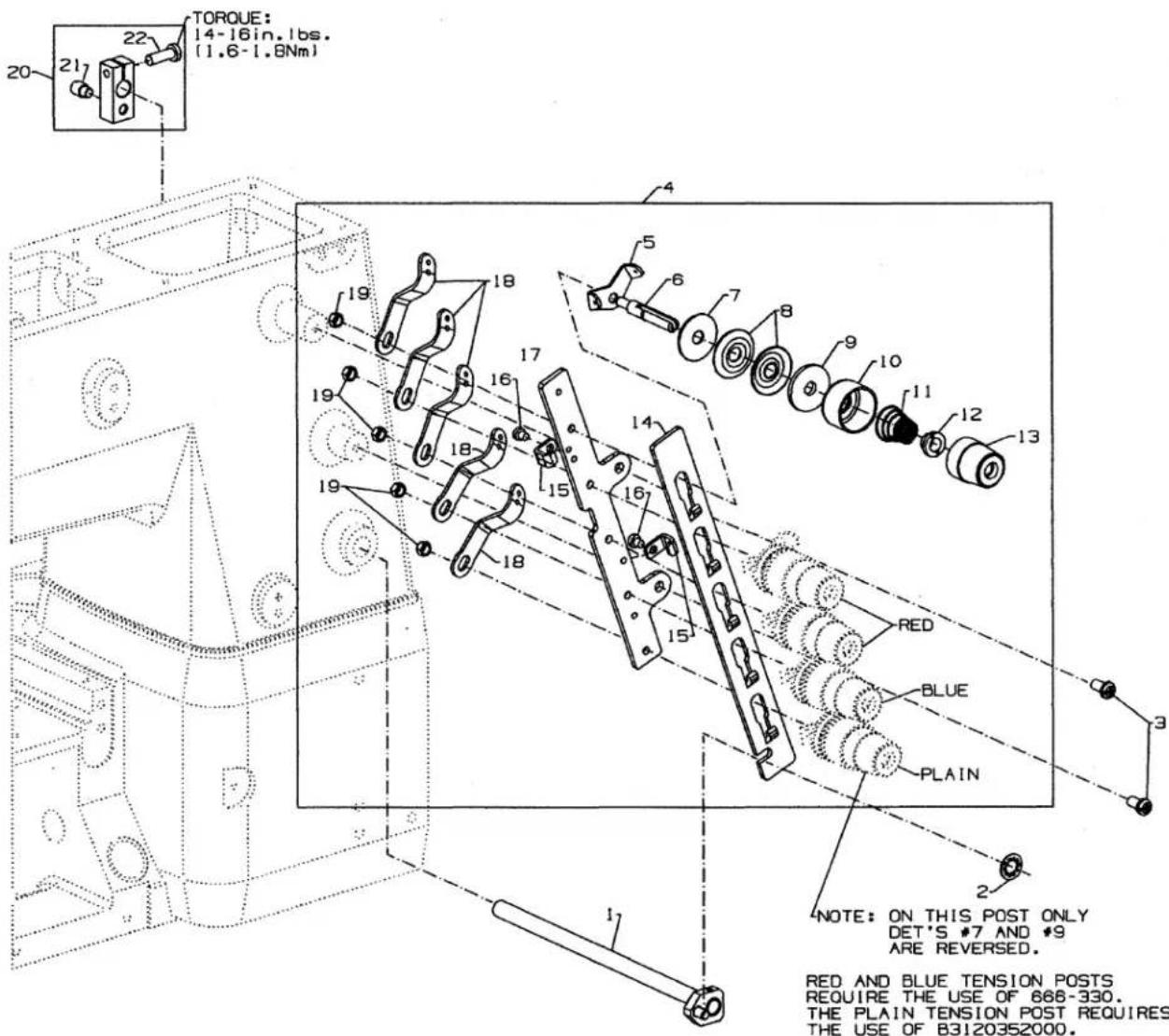
TORQUE: 14-16in.1bs. (1.6-1.8Nm) 20 21 22 4 5 6 7 8 9 10 11 12 13 14 15 16 17 18 19 19 18 19 RED BLUE PLAIN NOTE: ON THIS POST ONLY DET'S #7 AND #9 ARE REVERSED. RED AND BLUE TENSION POSTS REQUIRE THE USE OF 666-330. THE PLAIN TENSION POST REQUIRES THE USE OF B3120352000.TENSION RELEASE & THREAD TENSION
| Ref. | Amt. | ||
| No. | Part No. | Description | Req. |
- 50392Z Tension Needle Lever Assembly 1
- 660-283A Retainer Washer 1
- SS4120915SP Screw, for tension assembly 2
- 50392Y 5 Thread Tension Assembly 1
- 57892K Thread Tension Eyelet 5
- 56392G Tension Post 5
- B3120352000 Tension Disc Felt 1
- 666-330 Disc Felt 4
- B3126012000 Tension Disc 10
- B3120704000 Tension Disc Felt 5
- 56392H Spring Shield 5
- 11550209 Spring, needle (green) 3
- B3103804000 Spring, spreader (blue) 1
- B3121804000 Spring, looper (plain) 1
- B3112704000 Ferrule, tension spring 5
- 50692G Knob, needle (green) 3
- 56392M Knob, spreader (blue) 1
- 56392R Knob, looper (plain) 1
- 50392W Tension Disc Separator 1
- 50392AV Guide, for tension disc separator 2
- SS7090520SP Screw, for guide 2
- 50392X Tension Bracket 1
- 57865 Lead-In Thread Guide 5
- NS6110420SP Nut 5
- 50392BC Tension Release Lever Shaft Connection....1
- 22875N Base Spring Screw 1
- SS7121410TP Binder Screw 1
text_image
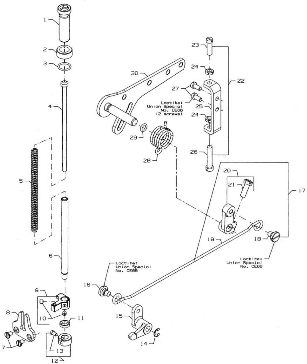
1 2 3 4 5 6 7 8 9 10 11 12 13 14 15 16 17 Loctite: Union Special No. CE66 (2 screws) Loctite: Union Special No. CE66 23 24 27 25 24 26 20 21 19 18 15 14 22 30PRESSER FOOT LIFT
Ref.
No. Part No.
Description
Amt.
Req.
- 11071602 Adjusting Screw, for spring 1
- 11071701 Locking Nut 1
- 660-1014 "O" Ring 1
- C50056B Spring Rod 1
- 50357AP Spring, for presser bar 1
- 50335AF Presser Bar 1
- SS6110610TP Screw, for guide plate 2
- 50335AG Guide Plate, for presser bar 1
- 50335AH Presser Bar Guide 1
- SS8110422TP SetScrew 2
- 660-739 Oil Seal 1
- 50333P Collar 1
- 22562 Screw 2
- RE0500000K0 E Ring, for pin 1
- 50381F Lever, for lifter, front 1
- SD0790303SP Screw, for wire connector 1
- CE66 Loctite Adhesive, (not shown), for screw
- 29476TK Rear Lifter Lever Assembly 1
- SD0790303SP Screw 1
- 50355AR Wire Connector 1
- 50381G Lifter Lever, rear 1
- SS9151740CP Hex Screw 1
- 29476TT Stop Assembly 1
- SS6151920SP Screw, for stopper 1
- NS6150310SP Hex Nut 2
- 50332V Stopper, for lifter lever 1
- SS6153040SP Screw, for adjusting stopper 1
- SS6121010SP Screw, for adjusting stopper 2
- CE66 Loctite Adhesive, (not shown), for screw
- 50381 Spring, for lifter lever 1
- RO068190100 "O" Ring 1
- 50381B Lifter Lever Assembly 1

text_image
Technical diagram of a mechanical assembly with numbered components and labeled parts including Union Special No. CE59 and CE27.COVERS, UPPER ARM
Ref.
No. Part No.
Description
Amt.
Req.
- SS4121615SP Screw, for top cover 6
- 50393EU Plug, for top cover 1
- B3530555000 Oil Sight Gauge, top 1
- 660-212 "O" Ring, for oil sight gauge 1
- 50382FW Top Cover 1
- 50382FZ Quad Ring, for top cover 1
- SS4120915SP Screw, for puller drive cover 4
- 50382GB Puller Drive Cover 1
- 50384L Gasket, for puller drive cover 1
- 50317C Needle Bar Guard 1
- SS7120640SP Screw, for needle bar guard 2
- 50393HB Plug 2
- TA1050504R0 Plug, for arm 1
- 50382FX Head Cover 1
- 50382FY Quad Ring, for head cover 1
- SS4121215SP Screw, for head cover 4
- TA1100604R0 Plug 1
- 99682XCB Sewing Guard Assembly 1
- NS6620320SP Nut 1
- 50383AE Bracket Holder 1
- 50383AD Bracket 1
- 99682XC Protection Shield 1
- SS1110640SL Counter Sunk Head Screw 2
- WZ0641510KP Spring Washer 1
- SD0640323TP Shoulder Screw 1
- 50337AW Plug....1
- 50393EW Rubber Gasket, for needle lever 1
- 50382JL Thread Take-Up Bracket 1
- SS7090530SP Screw 1
- SS4120615SP Screw, for thread cover 1
- SS4120915SP Screw, for thread take-up cover 1
- 50382JN Thread Take-Up Cover 1
- 666-334 Felt Wick 1
- 50382GM Thread Cover 1
- SS4120615SP Screw, for thread cover 1
- LA451 Label, in direction of rotation 1

text_image
TORQUE: 46-48 in.-lbs. (5.2-5.4 Nm) TORQUE: 46-48 in.-lbs. (5.2-5.4 Nm)LOWER MAIN SHAFT
Ref.
No. Part No.
Description
Amt.
Req.
- 34321CC Flange, synchronizer.... 1
- 95205 Screw 1
- 50321J Pulley 1
- SS8660612TP SetScrew 2
- 50335AP Adapter 1
- SS8660612TP Screw, for adapter 2
- 661-348 Retainer Ring.... 1
- 50344AR Bearing Adaptor Assembly 1
- SS8660612TP Screw 2
- 50335AP Adaptor 1
- 50311C Ball Bearing, for lower main shaft, right 1
- 50322AN Retainer, for sprocket 1
- 661-261 Load Ring 2
- 22569B Screw, for housing 3
- 50390L Rear Bearing Housing 1
- 99658 Housing Pin 1
- 56390E Housing Gasket 1
- 50342BD Timing Belt 1
- 50342BH Sprocket, for lower main shaft 1
- SS8660612TP SetScrew 2
- 50335BC Bearing Adapter Assembly 1
- SS8660612TP Screw 2
- 50322AH Lower Main Shaft, right 1
- 96162A Washer 1
- 50322BG Mainshaft, left 1

text_image
TO: OIL CONNECTOR 34394A (MAIN SHAFT BUSHING, OIL TUBE) TO: LOWER LEFT. REAR ON SIDE OF CASTING TO: CONNECTOR (A) IN OIL PUMP 50393HN TO: OIL CONNECTOR 34394 (ROCKER CROSS SHAFT, OIL TUBE) TO: CONNECTOR (B) IN OIL PUMP 50393HN TO: OIL CONNECTOR 34394B (RIGHT BOTTOM CAVITY OF CASTING)LUBRICATION, OIL TUBING & OIL PUMP
Ref.
No. Part No.
Description
Amt.
Req.
- 50393HN Oil Pump Assembly, 2 stage 1
- 50393GD Oil Pump Housing, 2 Stage 1
- 18-1470 Screw 2
- 50332S Spring, for plunger 2
- 34393D Plunger 2
- 50393GB Oil Pump Housing, 2 Stage 1
- 50393EX Collar 1
- SS8660612TP Screw 2
Screw 2
- 29476TR Oil Supply Trough Assembly 1
- 258A Nut 1
- 50393FH Oil Supply Trough 1
- 41350X Washer 2
- C50094B Connector Dual Feed 1
- 50393GT Oil Tube Cover 2
- 50393HE Plug Screw 1
- 50393FK Tube 1
- 29476TS Oil Supply Trough Assembly for CS122 and CS132 1
- 29476VL Oil Supply Trough Assembly for CS125 and CS135 1
- 50393FF Oil Tube 1
9A. 50393KV Oil Tube 1 - 50393FG Oil Tube 1
- 50393GU "T" Connector 1
- 50393FD Oil Tube 1
- 50393FE Oil Tube 1
- 50393LA Oil Screen 1
- 29476TJ Oil Filter Assembly 1
- 99349 Stud 1
- 660-212 "O" Ring 1
- 34393M Oil Screen Felt 1
- 34393L Oil Screen 1
- 96276 Retaining Ring 1
- 50393HV Oil Tube 1
- 34682C Gasket 1
- 999-254J Oil Filter 1
- 50382GS Base Plate 1
- 22571E Magnet Plug 6
- 95953 Washer 6
- 95406 Screw 1

text_image
TORQUE: 24-26 in.-Ibs. (2.7-2.9 Nm) 3 2 1 6 Three Bond: Union Special No. CE62 TORQUE: 22-24 in.-Ibs. (2.5-2.7 Nm) TORQUE: 19-21 in.-Ibs. (2.1-2.3 Nm) 13 12 11 18 15 16 19 17 25 24 TORQUE: 108 in.-Ibs. (12 Nm) TORQUE: 14-16 in.-Ibs. (1.6-1.8 Nm) TORQUE: 132.5 in.-Ibs. (14.7 Nm)LOOPER DRIVE
| Ref. | Amt. | ||
| No. | Part No. | Description | Req. |
- 34709D Looper.... 1
- 50348 Holder, for looper 1
- SS6091022TP Screw 1
- SS6090560TP Screw 1
- 50313T Washer 1
- 22894C Screw 2
- 50344AG Bushing....1
- 99652A Washer 2
- 9937 Nut 1
- 29476VK Looper Drive Assembly 1
- 50343RC Bushing, for looper bar, right 1
- 34344A Cam Guide 1
- 34344E Cam Follower 1
- 50344BM Bushing, for loopershaft 1
- 22894W Screw 1
- 39543E Locking Clamp 1
- 34344D Cam Guide Holder 1
- 22541B Screw 1
- 51235G Washer 1
- 34343C Washer 1
- 34642A Looper Rocker Lever 1
- HA20B Washer 1
- 22811B Screw 1
- 50343B Shaft, for looper 1
- CO67D Cork 1
- 34893 Oil Seal Plug, front 1
- 661-253 "O" Ring 1
- 50343C Looper Rocker Shaft 1
- 34342J Binder Collar 1
- 22652A12 Screw 1
- 56390H Thrust Washer 2
- 661-252 Snap Ring 1
- 29105BK Looper Eccentric Assembly 1
- G29105F Drive Lever Crank 1
- 22894X Screw 4
- 99346 SetScrew 1
- 50335BE Looper Avoid Link 1
- 50314G Looper Avoid Eccentric 1
- SS8660512TP Screw 1
- 99343 Screw 1

text_image
1 2 3 4 5 6 7 8 9 10 11 12 13 14 15 16 17 18 19 20 21 22 23 24 25 26 27 28 Three Bond: Union Special No. CE62LOOPER THREAD TAKE -UP & NEEDLE GUARD
Ref.
No. Part No.
Description
Amt.
Req.
- 29476UA Cast-Off Plate Assembly 1
- SS7060310SP Screw 2
- 34358BA Thread Guide, left 1
- SS4080620TP Screw 2
- WP0320501SC Washer 2
- 34358CA Thread Guide, right 1
- 50357AK Cast-Off Plate 1
- RE0900000K0 Retaining Ring 1
- 50357AH Spring 1
- 50357AG Holder 1
- 50304M Finger.... 1
- SS7080520SP Screw 2
- 50357AJ Shaft, for cast-off 1
- 50325AL Needle Guard, front 1
- 50325AB Holder, for needle guard, front 1
- SS8090540SP Screw 1
- 50325AM Holder, for needle guard, rear 1
- SS6090440SP Screw 1
- 50325AN Needle Guard, rear 1
- 22580 Screw 1
- 6042A Washer 1
- 50333H Spacer 1
- 77A Screw 1
- 34368 Fork 1
- 22894AD Screw 1
- 34366 Collar 1
- 22743 Screw 1
- 50323S Take Up 1
- 22894T Screw 2
FEED DRIVE MECHANISM
Ref.
No. Part No.
Description
Amt.
Req.
-
G29476BV Feed Bar Assembly 1
-
9937 Nut 1
-
34336N Drive Connection.... 1
-
39536C Bushing 1
-
J87J Screw 4
-
50386L Thrust Plate, differential 1
-
34353A Differential Feed Dog Holder 1
-
50386M Thrust Plate, main 1
-
34353 Main Feed Dog Holder 1
-
34336U Stud 1
-
29476SH Feed Bar Assembly 1
-
34334S Main and Differential Feed Bar 1
-
34338 Feed Lift Slide Block 1
-
34338B Sliding Block 1
-
GA29477AP Eccentric Assembly 1
-
34336S Spacing Stop 1
-
90 Screw 1
-
96663 Roll Pin 1
-
22738B Screw 2
-
34336RA Washer 1
-
97137 Disc Spring 2
-
34336V Cam Disc 1
-
96667 Roll Pin 1
-
22562A Screw 1
-
34336Q Guide, foreccentric 1
-
22738B Screw 1
-
34340A Eccentric 1
-
22503F Screw 2
-
50322BF Feed Lift Shaft 1
-
34335J Collar 2
-
22894X SetScrew 2
-
34336A Differential Feed Drive Link 1
-
34337F Eccentric Bushing 1
-
22874C Screw 1
-
93 Screw 2
-
34335G Feed Bar Guide 1
-
34382H Gasket 1

text_image
TORQUE: 46-48 in.-Ibs. (5.2-5.4 Nm) TORQUE: 30-32 in.-Ibs. (3.4-3.6 Nm) TORQUE: 37-40 in.-Ibs. (4.2-4.5 Nm)FEED DRIVE MECHANISM
Ref.
No. Part No.
Description
Amt.
Req.
-
29476XT Feed Drive Assembly 1
-
50367S Feed Lifter Lever 1
-
SS8660612TP Set Screw 2
-
G51054 Link Pin 1
-
666-149 Felt Wick 1
-
29476SJ Feed Bar Subassembly 1
-
999-215 Snap Ring 2
-
34306D Double Eccentric 1
-
22894AD Screw 2
-
34335 Connecting Rod Link, for feed link 1
-
34335A Connecting Rod, for differential feed 1
-
34337 Link Pin.... 1
-
34337A Pitman Rod 1
-
34337B Connecting Rod 1
-
50347T Link Pin.... 1
-
34337CA Differential Feed Drive Lever 1
-
SS6121010SP Screw 1
-
RC0980615K0 Shim Ring 1
-
34335D Guide Stud 1
-
96719 Spring 1
-
50383Y Bracket 1
-
SS8110422TP SetScrew 1
-
96865 Dowel Pin, Grooved 1
-
34337 Link Pin.... 1
-
SS8150822TP SetScrew 1
-
PH0400104U0 Hinge Pin 1
-
50367T Lever 1
-
50337AP Knob 1
-
SS8110422TP SetScrew 3
-
B3215470000 Pin 1
-
50395T Stud 1
-
999-211E "O" Ring 1
-
29476TP Cast-off Plate Release Assembly 1
-
34363C Stop 1
-
34363B Pawl 1
-
34363 Pawl Support 1
-
34363A Spring 1
-
22894W Screw 1
-
28B Screw 1
-
22894BD Set Screw 2
-
34335H Feed Bar Guide 1
-
22569G Screw 2
-
34335D Guide Stud 1
-
34335J Collar 1
-
22894X Screw 1
-
34334A Feed Drive Shaft 1
-
34336P Link Pin 1
-
666-149 Felt Wick 1

text_image
Technical diagram of a mechanical assembly with numbered components and exploded viewsCOVERS
FOR
CS122E11, CS132E11, CS125E61, CS125E62,
CS135E61, CS135E62
Ref.
Amt.
No. Part No.
Description
Req.
-
25S Screw 2
-
50389 Guide Roller Assembly 1
-
22561 Screw 8
-
34786D Guide Roller 2
-
34786C Bracket, right 2
-
34786B Bracket, left 2
-
50389A Mounting Bracket 1
-
50302 Slide Cover 1
-
29476UN Throat Plate Support Assembly 1
-
34367 Rest Bolt 1
-
97014 Spring.... 1
-
95685 Screw 1
-
34367B Safety Latch.... 1
-
34780 Throat Plate Support 1
-
96277 "E" Ring 1
-
99364L Shank Screw 1
-
69H Washer 1
-
50396G Splash Guard 1
-
22562B Screw 1
-
99697J Latch Spring 1
-
22746 Screw, for handle 1
-
2165D-0.2 Washer 1
-
50384F Gasket 1
-
34382W Handle 1
-
C50063N Washer 1
-
50382HU Cylinder Cover 1
-
22894AY Set Screw 1
-
50382JA Hinge, for cylinder cover 1
-
34382V Pin, for hinge 1
-
34382UA Gasket, for hinge 1
-
22541B Screw, for hinge 2
-
376 Screw 2
-
34778GD Suction Tube Assembly 1
-
90 Screw 2
-
80265 Washer 1
-
34778GF Bracket 1
-
G50-748D Cover 1
-
99675QA-400 Spiral Hose 1
-
671C23 Hose Clamp 1
-
50301BW Cloth Plate, front 1
-
50364X Swing Out Cloth Plate Support 1
-
99301A Screw 1
-
9937 Nut 1
-
50364Y Folder Support....1
-
99356 Stop Screw 2
-
99350 Screw 1
-
97127 Cup Spring 2
-
95 Screw 1
-
99351 Screw 1
-
50364S Hinge Plate 1
-
99392 Screw 1
-
660-212 Oil Ring 1
-
29480ARN Treadle Assembly 1
text_image
Technical diagram of mechanical assembly with numbered components and exploded views, likely from an engineering or manufacturing context.COVERS LOWER BED- FRONT
| Ref. | Amt. | ||
| No. | Part No. | Description | Req. |
-
29476TU Cylinder Cover Assembly 1
-
22562B Screw 1
-
99697J Latch Spring 1
-
22746 Screw, for handle 1
-
2165D-0.2 Spring Washer, for handle 1
-
34382W Handle 1
-
50384F Gasket 1
-
C50063N Washer 1
-
50382FV Cylinder Cover 1
-
22894AY Screw 1
-
50382FU Hinge, for cylinder cover 1
-
34382V Pin, for hinge 1
-
22541B Screw, for hinge 2
-
34382UA Gasket, for hinge 1
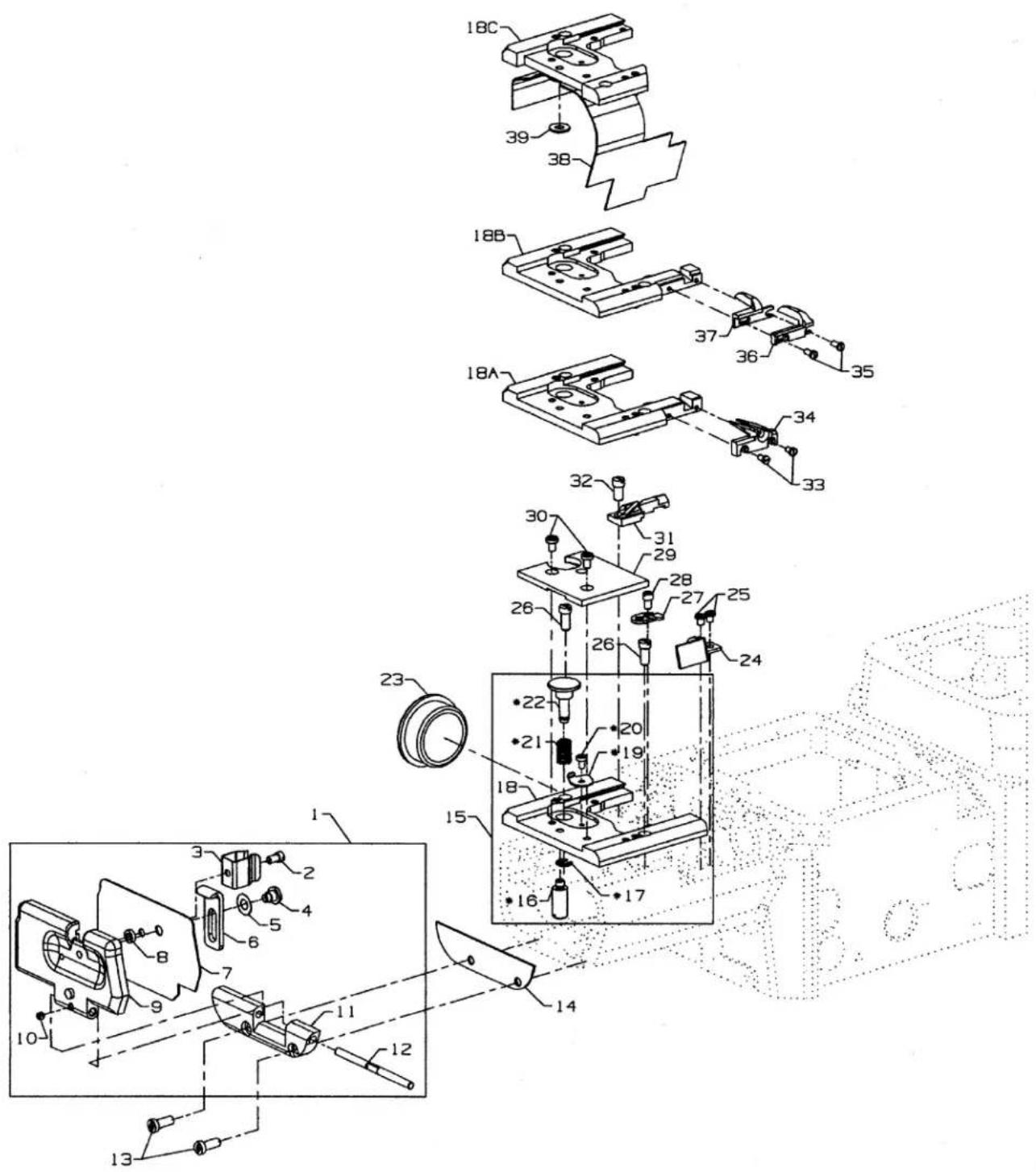
*15. 29476TV Throat Plate Support Assembly, for styles CS122H01, CS132H01,
CS125H11, CS125H12, CS135H11, CS135H12 1
*16. 99364L Shank Screw 1
-
96277 Retaining Ring 1
-
34380 Throat Plate Support, for styles CS122H01, CS132H01, CS125H11,
CS125H12, CS135H11, CS135H12 1
18A. 34780CA Throat Plate Support, for styles CS122K01, CS132K01 1
18B. 34780CB Throat Plate Support, for styles CS122K02, CS132K02 1
18C. 34380T Throat Plate Support, for styles CS122H21, CS132H21 1
*19. 34367B Safety Latch 1
*20. 95685 Screw 1
*21. 97014 Spring.... 1
-
34367 Stop Bolt 1
-
50393EU Plug, for top 1
-
50382GV Plate Cover 1
-
SS6090420SP Screw, for plate cover 2
-
J79J Screw 2
-
34381A Support for Slide 1
-
91 Screw, for support for slide 1
-
34367A Cover, for throat plate support 1
-
90 Screw 2
-
34381B Rest for Slide 1
-
79 Screw, for rest for slide 1
-
605C Screw, for material guide, for styles CS122K01, CS132K01 1
-
34703CA Material Guide, for styles CS122K01, CS132K01 1
-
605D Screw, for material guides, for styles CS122K02, CS132K02 .... 1
-
34703B Material Guie, right, for styles CS122K02, CS132K02 .... 1
-
34703A Material Guide, left, for styles CS122K02, CS132K02 .... 1
-
50396G Splash Guard, for styles CS122H21, CS132H21 1
-
69H Washer, for splash guard, for styles CS122H21, CS132H21 1
*NOTE: For the throat plate support numbers 18A., 18B., 18C., asteric items must be ordered separately to make a complete throat plate support assembly.
text_image
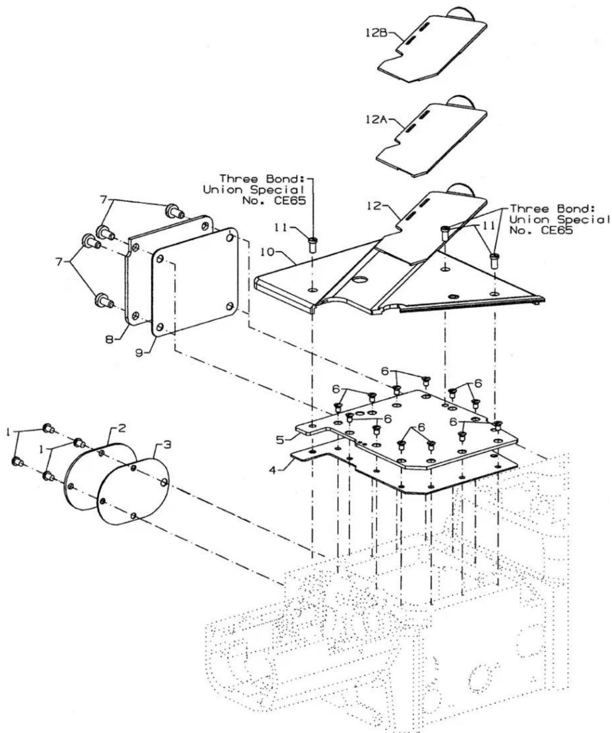
12B 12A Three Bond: Union Special No. CE65 11 10 7 8 9 3 5 4 6 6 6 6 6 3 2 1COVERS LOWER BED- MIDDLE
| Ref. | Amt. | ||
| No. | Part No. | Description | Req. |
- SS4120615SP Screw 4
- 35082E Plate 1
- 35082F Gasket 1
- 34382EA Gasket, for oil reservoir cover 1
- 34382J Oil Reservoir Cover 1
- 87 Screw, for oil reservoir cover 12
- 22548 Screw, for chamber cover 4
- 56382D Chamber Cover 1
- 34782C Chamber Cover Gasket 1
- 50301CP Cloth Plate Assembly 1
- 22569AH Screw, for cloth plate 3
- 50382HX Slide Cover, for styles CS122H01, CS122K01 CS122K02, CS132H01, CS132K01, CS132K02.... 1
12A. 50302D Slide Cover, for styles CS125H11, CS125H12, CS135H11, CS135H12.... 1
12B. 50302A Slide Cover, for styles CS122H21, CS132H21 1
text_image
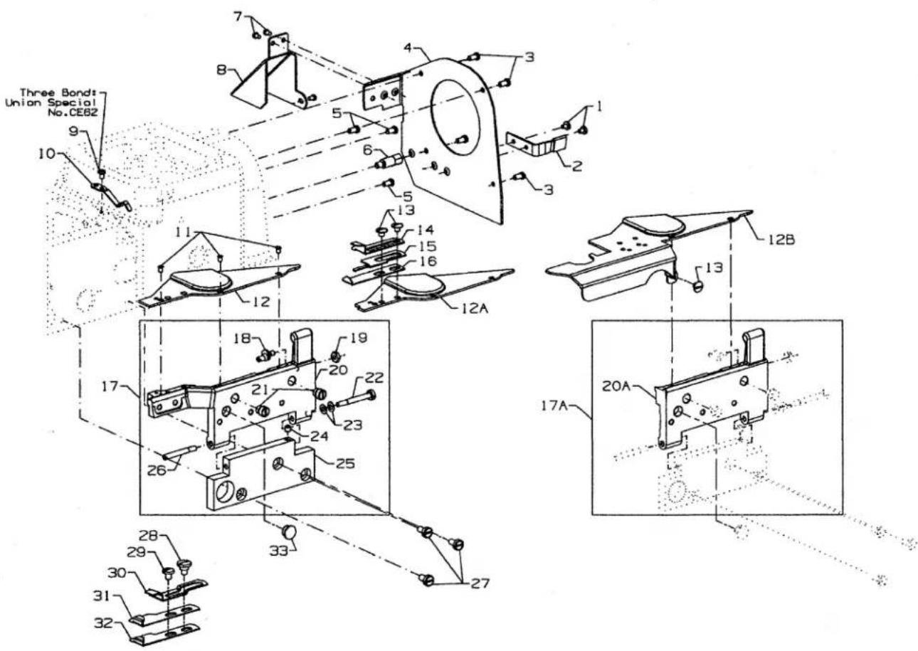
Three Bonds Union Special No.CEB2 7 8 5 4 3 1 2 3 9 10 11 12 13 14 15 16 12A 12B 13 17 18 19 20 21 22 23 24 25 26 27 28 29 30 31 32 33 17A 20ACOVERS LOWER BED - REAR
| Ref. | Amt. | ||
| No. | Part No. | Description | Req. |
| 1. | 22585C | Screw | 2 |
| 2. | 34767K | Synchronizer Stop | 1 |
| 3. | 22569C | Screw | 4 |
| 4. | 50395J | Belt Guard | 1 |
| 5. | 22757E | Screw | 3 |
| 6. | 50395U | Spacer Stud | 1 |
| 7. | SS4090515SP | Screw | 3 |
| 8. | 50382GR | Belt Guard | 1 |
| 9. | SM4040655SP | Screw | 1 |
| 10. | 43281K | Latch Spring | 1 |
| 11. | 22766 | Screw | 3 |
| 12. | 50301BK | Cloth Plate | 1 |
| 12A. | 50364VB | Cloth Plate, for styles CS125H11, CS125H12, CS135H11, CS135H12 | 1 |
| 12B. | 50301BX | Cloth Plate, for styles CS122H21, CS132H21 | 1 |
| 13. | 22730 | Screw, for cloth plate for styles CS122H21, CS132H21 | 3 |
| 14. | 34703ZA | Folder Upper, for styles CS122H21, CS132H21 | 1 |
| 15. | 34703Z | Folder, for styles CS122H21, CS132H21 | 1 |
| 16. | 34703ZB | Folder L, for styles CS122H21, CS132H21 | 1 |
| 17. | 29476SA | Swing-Out Cloth Plate Support, for styles CS122H01, CS132H01, CS125H11, CS125H12, CS135H11, CS135H12, CS122K01, CS122K02, CS132K01, CS132K02 | 1 |
| 17A. | 29476TA | Swing-Out Cloth Plate Support, for styles CS122H21, CS132H21 | 1 |
| 18. | 99301A | Eccentric Screw | 1 |
| 19. | 9937 | Nut | 1 |
| 20. | 50364R | Cloth Plate Support, for styles CS122H01, CS132H01, CS125H11, CS125H12, CS135H11, CS135H12, CS122K01, CS122K02, CS132K01, CS132K02 | 1 |
| 20A. | 50364Z | Cloth Plate Support, for styles CS122H21, CS132H21 | 1 |
| 21. | 99356 | Stop Screw | 2 |
| 22. | 99350 | Shoulder Screw | 1 |
| 23. | 97127 | Spring Washer | 2 |
| 24. | 95 | Set Screw | 1 |
| 25. | 50364S | Hinge Plate | 1 |
| 26. | 99351 | Screw | 1 |
| 27. | 22548 | Screw | 3 |
| 28. | 22715A | Screw, for CS122H01, CS132H01 | 1 |
| 29. | 25S | Screw, for CS122H01, CS132H01 | 1 |
| 30. | 34703F3 | Hemmer, upper, for styles CS122H01, CS132H01 | 1 |
| 31. | 34703F1 | Hemmer, lower, for styles CS122H01, CS132H01 | 1 |
| 32. | 34703FA1 | Hemmer, lower, for styles CS122H01, CS132H01 | 1 |
| 33. | TA1100604R0 | Plug | 1 |

| MODEL | NEEDLE HEAD | PRESSER FOOT ASSEMBLY | THROAT PLATE | FEED DOG MAIN | FEED DOG DIFFERENTAIL |
| CS125E61-2D40 | 50318AN40 | 34720TB40 | 34724TB40 | 34705BW | 34726TB10 |
| CS125E61-2D48 | 50318AN48 | 34720TB48 | 34724TB48 | ||
| CS125E61-3D56 | 50318AN56 | 34720TB64 | 34724TB56 | 34705TB | 34726TB16 |
| CS125E61-3D64 | 50318AN64 | 34724TB64 | |||
| CS135E61-2D40 | 50318AN40 | 34720TB40 | 34724TB40 | 34705BW | 34726TB10 |
| CS135E61-2D48 | 50318AN48 | 34720TB48 | 34724TB48 | ||
| CS135E61-3D56 | 50318AN56 | 34720TB64 | 34724TB56 | 34705TB | 34726TB16 |
| CS135E61-3D64 | 50318AN64 | 34724TB64 | |||
| CS125E62-2D40 | 50318AN40 | 34720TB40 | 34724TB40 | 34705BW | 34726TB10 |
| CS125E62-2D48 | 50318AN48 | 34720TB48 | 34724TB48 | ||
| CS125E62-3D56 | 50318AN56 | 34720TB64 | 34724TB56 | 34705TB | 34726TB16 |
| CS125E62-3D64 | 50318AN64 | 34724TB64 | |||
| CS135E62-2D40 | 50318AN40 | 34720TB40 | 34724TB40 | 34705BW | 34726TB10 |
| CS135E62-2D48 | 50318AN48 | 34720TB48 | 34724TB48 | ||
| CS135E62-3D56 | 50318AN56 | 34720TB60 | 34724TB56 | 34705TB | 34726TB16 |
| CS135E62-3D64 | 50318AN64 | 34724TB64 |
SEWING PARTS
FOR
CS122E11, CS125E61, CS125E62,
CS132E11, CS135E61, CS135E62
Ref.
No. Part No.
Description
Amt.
Req.
- Needle Head, for sewing comb., on two needle machines (see chart).... 1
1A. - - - - - Needle Head, for sewing comb., on three needle machines (see chart) 1
-
SS5060410TP Screw 1
-
50318AE40 Eyelet, for sewing comb., on two needle machines (see chart) ..... 1
3A. 50318AE56 Eyelet, for sewing comb., on three needle machines (see chart) ..... 1
-
SS8080310SP Screw 3/4
-
50392G Needle Thread Eyelet 1
-
-
-
-
-
- Presser Foot Assembly, forsewing comb., on two needle machines (see chart).... 1
-
-
-
-
6A. - - - - - Presser Foot Assembly, for sewing comb., on three needle machines (see chart).... 1
-
50330FP Shank 1
-
SM7040800SL Screw 1
-
18C1475 Screw 1
-
NM6030001SD Nut 1
-
PH0300164C0 Pin 1
-
50330FS Screw 1
-
50330FM40 Presser Foot Bottom, for sewing comb.; CE11-2D40 (see chart) ...... 1
13A. 50330FM48 Presser Foot Bottom, for sewing comb.; CE11-2D48 (see chart) ..... 1
- 50330FM56 Presser Foot Bottom, for sewing comb.; CE11-3D56, CE11-3D64 (see chart) ..... 1
-
50330FN Yielding Section Shank 1
-
SM4030455SP Screw 1
-
50330GN Elastic Guide 1
-
50330GR Yielding Section 1
-
PH0200063C0 Pin.... 1
-
52730Y Spring.... 1
-
18C1479 Shoulder Screw 1
-
50330FR Torsion Spring 1
-
50330FU Screw 1
-
87 Screw 2
-
---- Throat Plate, for two needle machines (see chart) 1
24A. ---- Throat Plate, for three needle machines (see chart) 1
-
99293 Screw 2
-
-
-
-
-
- Main Feed Dog, for two needle machines (see chart) 1
-
-
-
-
26A. - - - - - Main Feed Dog, for three needle machines (see chart) 1
-
-
-
-
-
- Differential Feed Dog, for two needle machines (see chart) 1
-
-
-
-
27A. - - - - - - Differential Feed Dog, for three needle machines (see chart) 1
| MODEL | NEEDLE HEAD | PRESSER FOOT ASSEMBLY | THROAT PLATE | FEED DOG MAIN | FEED DOG DIFFERENTAIL |
| CS122E11-2D40 | 50318AN40 | 34720TB40 | 34724TB40 | 34705BW | 34726TB10 |
| CS122E11-2D48 | 50318AN48 | 34720TB48 | 34724TB48 | ||
| CS122E11-3D56 | 50318AN56 | 34720TB64 | 34724TB56 | 34705TB | 34726TB16 |
| CS122E11-3D64 | 50318AN64 | 34724TB64 | |||
| CS132E11-2D40 | 50318AN40 | 34720TB40 | 34724TB40 | 34705BW | 34726TB10 |
| CS132E11-2D48 | 50318AN48 | 34720TB48 | 34724TB48 | ||
| CS132E11-3D56 | 50318AN56 | 34720TB64 | 34724TB56 | 34705TB | 34726TB16 |
| CS132E11-3D64 | 50318AN64 | 34724TB64 |
SEWING PARTS FOR CS122H01, CS132H01
Ref.
No. Part No.
Description
Amt.
Req.
- Needle Head, on two needle machines, (see chart) 1
1A. ---- Needle Head, on three needle machines, (see chart) 1
-
SS5060410SP Set Screw 3/4
-
50318AE40 Eyelet, for 4.0, 4.8 gauges (see chart) 1
3A. 50318AE56 Eyelet, for 5.6, 6.4 gauges (see chart).... 1
-
SS6060440TP Screw 1
-
50392G Needle Thread Eyelet 1
-
-
-
-
-
- Presser Foot Assembly, for sewing comb., (see chart) 1
-
-
-
-
-
G65-134 Presser Foot Shank 1
-
91 Screw 1
-
G50-266 Bushing 2
-
22716A Screw 1
-
50397A48 Stitch Tongue, for 4.8 gauge 1
11A. 50397C Stitch Tongue, for 4.0 gauge 1
- 50397A16 Stitch Tongue, for 5.6, 6.4 gauges 1
-
50330BL16 Presser Foot Bottom 1
-
57830A Yielding Section 2
-
6-25-55 Drill Rod 3
-
605 Screw 1
-
79633 Spring 1
-
HT2C Screw 1
-
34703W2.3 Throat Plate Edge Guide 1
- 34703W4.3 Throat Plate Edge Guide 1
- ---- Throat Plate, for two needle machines (see chart) 1
19A. ---- Throat Plate, for three needle machines (see chart) 1
-
87 Screw, for throat plate 2
-
99293 Screw, for feed dogs.... 1
-
Differential Feed Dog (see chart) 2
-
-
-
-
-
- Main Feed Dog (see chart) 1
-
-
-
-
| MODEL | NEEDLE HEAD | PRESSER FOOT ASSEMBLY | THROAT PLATE | FEED DOG MAIN | FEED DOG DIFFERENTAIL |
| CS122H01-2A40 | 50318AN40 | 50320AH | 50324BL40 | 34705F | 34726F |
| CS122H01-2C40 | 34724F10 | ||||
| CS122H01-2A48 | 50318AN48 | 50320T48 | 50328BL48 | ||
| CS122H01-2C48 | 50324F48 | ||||
| CS122H01-3A56 | 50318AN56 | 50320T60 | 50324BL56 | ||
| CS122H01-3B56 | 50324BS56 | ||||
| CS122H01-3C56 | 34724F56 | ||||
| CS122H01-3A64 | 50318AN64 | 50320T60 | 50324BL64 | ||
| CS122H01-3B64 | 50324BS64 | ||||
| CS122H01-3C64 | 34724F64 | ||||
| CS132H01-2A40 | 50318AN40 | 50320AH | 50324BL40 | 34705F | 34726F |
| CS132H01-2C40 | 34724F10 | ||||
| CS132H01-2A48 | 50318AN48 | 50320T48 | 50328BL48 | ||
| CS132H01-2C48 | 50324F48 | ||||
| CS132H01-3A56 | 50318AN56 | 50320T60 | 50324BL56 | ||
| CS132H01-3B56 | 50324BS56 | ||||
| CS132H01-3C56 | 34724F56 | ||||
| CS132H01-3A64 | 50318AN64 | 50320T60 | 50324BL64 | ||
| CS132H01-3B64 | 50324BS64 | ||||
| CS132H01-3C64 | 34724F64 |

text_image
Technical diagram of a mechanical assembly with numbered components and a zoomed-in detail view
text_image
1A 3A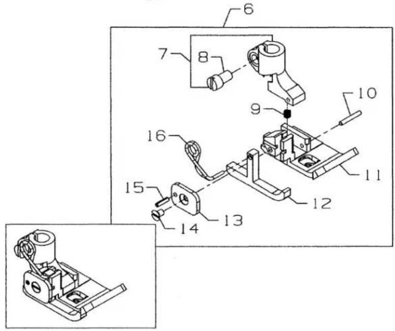
text_image
Technical diagram of a mechanical assembly with numbered components, including a bracket and housing assembly.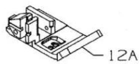

text_image
17A 17 18
text_image
19 20 21 21SEWING PARTS
FOR
CS125H11, CS125H12, CS135H11, CS135H12
Ref.
No. Part No.
Description
Amt.
Req.
1.
1A.
-
SS8080310TP
-
50318AE40
3A. 50318AE56
-
SS5060410SP
-
50392G
-
......
-
G57730GB
-
91
-
39568J
-
61330B41
-
50330BH40
11A. 50330BH64
-
34730A
-
G57730GC
-
22716
-
96651
-
G57730GD
-
17A. ----
-
87
-
20.
- 99293
Needle Head, for two needle machines (see chart pages 50-51) .... 1
Needle Head, for three needle machines (see chart pages 50-51) ..... 1
Screw 1
Needle Eyelet, for 4.0, 4.8 gauges 1
Needle Eyelet, for 5.6, 6.4 gauges 1
Screw 3/4
Needle Thread Eyelet 1
Presser Foot Assembly, for 4.0, 4.8 gauges (see chart pages 50-51) ..... 1
Presser Foot Assembly, for 5.6, 6.4 gauges (see chart pages 50-51) ..... 1
Shank 1
Screw 1
Pressure Spring 1
Pin 1
Presser Foot Bottom, for 4.0, 4.8 gauges 1
Presser Foot Bottom, for 5.6, 6.4 gauges 1
Yielding Section 1
Plate 1
Screw 1
Roll Pin 1
Torsion Spring 1
Throat Plate, for two needle machines (see chart pages 50-51)....1
Throat Plate, for three needle machines (see chart pages 50-51) .... 1
Screw, for throat plates 2
Main Feed Dog (see chart pages 50-51) 1
Differential Feed Dog (see chart pages 50-51) 1
Screw, for feed dogs 2
SEWING CHART
FOR
CS125H11, CS135H11
| MODEL | NEEDLE HEAD | PRESSER FOOT ASSEMBLY | THROAT PLATE | FEED DOG MAIN | FEED DOG DIFFERENTAIL |
| CS125H11-2A40 | 50318AN40 | 50320BE40 | 50324CJ40 | 34705DG | 34726DG |
| CS125H11-2C40 | 34724E10 | ||||
| CS125H11-2A48 | 50318AN48 | 50324CJ48 | |||
| CS125H11-2C48 | 34724E48 | ||||
| CS125H11-3A56 | 50318AN56 | 50320BF64 | 50324CK56 | ||
| CS125H11-3B56 | 50324CL56 | ||||
| CS125H11-3C56 | 34724E56 | ||||
| CS125H11-3A64 | 50318AN64 | 50324CK64 | |||
| CS125H11-3B64 | 50324CL64 | ||||
| CS125H11-3C64 | 34724E64 | ||||
| CS135H11-2A40 | 50318AN40 | 50320BE40 | 50324CJ40 | ||
| CS135H11-2C40 | 34724E10 | ||||
| CS135H11-2A48 | 50318AN48 | 50324CJ48 | |||
| CS135H11-2C48 | 34724E48 | ||||
| CS135H11-3A56 | 50318AN56 | 50320BF64 | 50324CK56 | ||
| CS135H11-3B56 | 50324CL56 | ||||
| CS135H11-3C56 | 34724E56 | ||||
| CS135H11-3A64 | 50318AN64 | 50324CK64 | |||
| CS135H11-3B64 | 50324CL56 | ||||
| CS135H11-3C64 | 34724E64 |
SEWING CHART
FOR
CS125H12, CS135H12
| MODEL | NEEDLE HEAD | PRESSER FOOT ASSEMBLY | THROAT PLATE | FEED DOG MAIN | FEED DOG DIFFERENTAIL |
| CS125H12-2A40 | 50318AN40 | 50320BE40 | 50324CJ40 | 34705DG | 34726DG |
| CS125H12-2C40 | 34724E10 | ||||
| CS125H12-2A48 | 50318AN48 | 50324CJ48 | |||
| CS125H12-2C48 | 34724E48 | ||||
| CS125H12-3A56 | 50318AN56 | 50320BF64 | 50324CK56 | ||
| CS125H12-3B56 | 50324CL56 | ||||
| CS125H12-3C56 | 34724E56 | ||||
| CS125H12-3A64 | 50318AN64 | 50324CK64 | |||
| CS125H12-3B64 | 50324CL64 | ||||
| CS125H12-3C64 | 34724E64 | ||||
| CS135H12-2A40 | 50318AN40 | 50320BE40 | 50324CJ40 | ||
| CS135H12-2C40 | 34724E10 | ||||
| CS135H12-2A48 | 50318AN48 | 50324CJ48 | |||
| CS135H12-2C48 | 34724E48 | ||||
| CS135H12-3A56 | 50318AN56 | 50320BF64 | 50324CK56 | ||
| CS135H12-3B56 | 50324CL56 | ||||
| CS135H12-3C56 | 34724E56 | ||||
| CS135H12-3A64 | 50318AN64 | 50324CK64 | |||
| CS135H12-3B64 | 50324CL56 | ||||
| CS135H12-3C64 | 34724E64 |
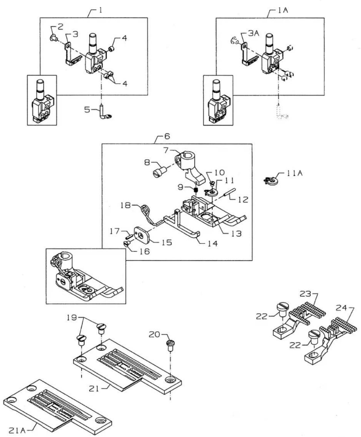
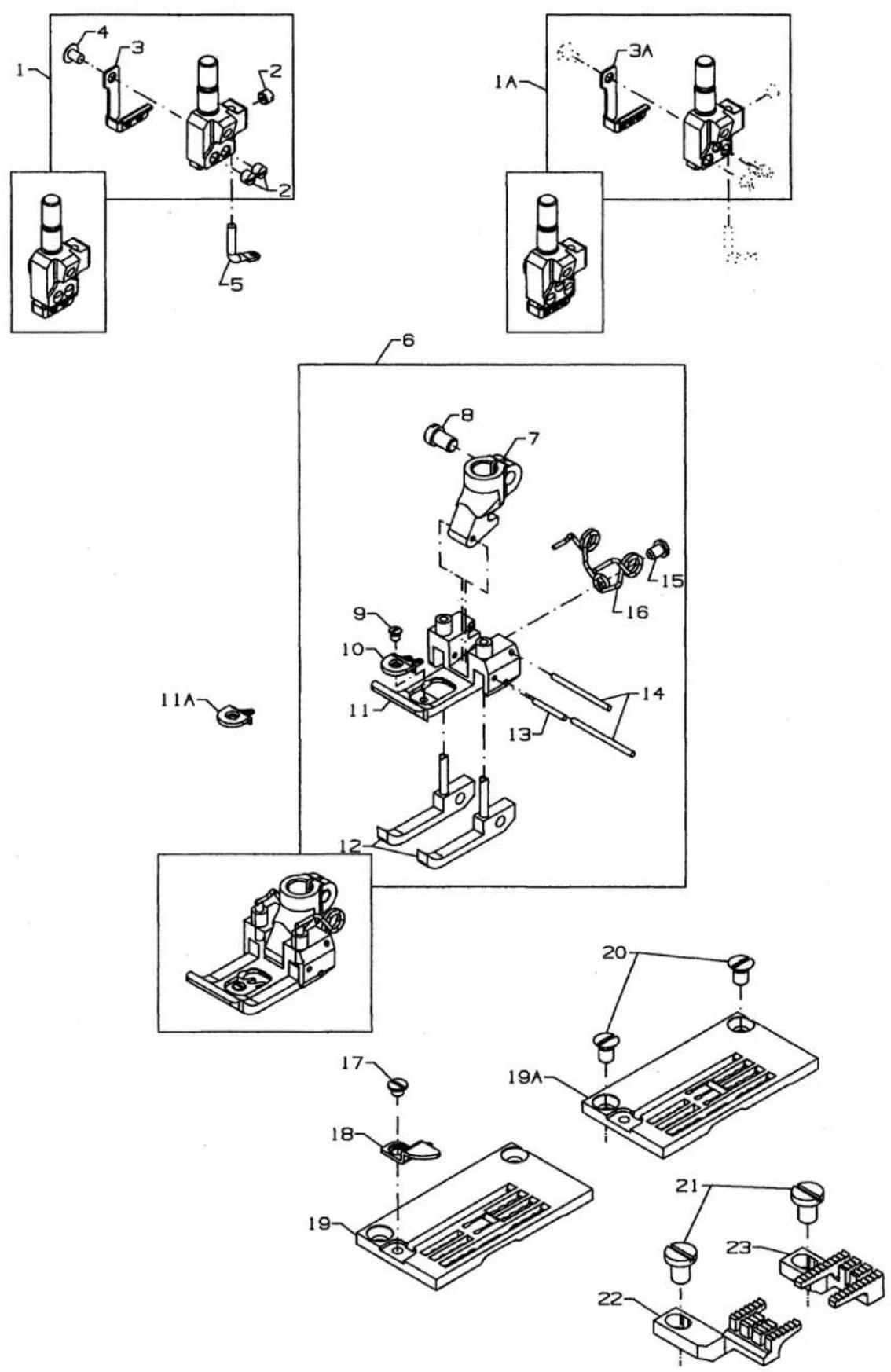
SEWING PARTS
FOR
CS122H21, CS132H21
Ref.
No. Part No.
Description
Amt.
Req.
- Needle Head, for sewing comb., on two needle machines (see chart) 1
1A. ---- Needle Head, for sewing comb., on three needle machines (see chart).... 1
-
SS6066440TP Screw 1
-
50318AE40 Eyelet, for 4.0, 4.8 gauges 1
3A. 50318AE56 Eyelet, for 5.6, 6.4 gauges 1
-
SS8080310TP Screw 3/4
-
50392G Needle Thread Eyelet 1
-
-
-
-
-
- Presser Foot Assembly, for sewing comb. (see chart) 1
-
-
-
-
-
G57730GB Presser Foot Shank 1
-
91 Screw 1
-
39568J Spring 1
-
22716A Screw 1
-
50397C Stitch Tongue 1
11A. 50397A16 Stitch Tongue 1
-
61330B42 Drill Rod 1
-
50330DU64 Presser Foot Bottom 1
-
34730AT Yielding Section 1
-
G57730GC Plate 1
-
22716 Screw 1
-
96651 Roll Pin.... 1
-
G57730GD Spring 1
-
87 Screw, for throat plate 3
-
22768 Screw, for throat plate 1
-
---- Throat Plate, for two needle machines (see chart) 1
21A. ---- Throat Plate, for three needle machines (see chart) 1
-
99293 Screw, for feed dogs 2
-
Differential Feed Dog (seechart) 1
-
Main Feed Dog (see chart) 1
| MODEL | NEEDLE HEAD | PRESSER FOOT ASSEMBLY | THROAT PLATE | FEED DOG MAIN | FEED DOG DIFFERENTAIL |
| CS122H21-2A40 | 50318AN40 | 50320GE40 | 34724FR40 | 34705FT | 34726FT |
| CS122H21-2C40 | 34724FT40 | ||||
| CS122H21-2A48 | 50318AN48 | 34724FR48 | |||
| CS122H21-2C48 | 34724FT48 | ||||
| CS122H21-3A56 | 50318AN56 | 50320BG 64 | 34724FR56 | ||
| CS122H21-3B56 | 34724FS56 | ||||
| CS122H21-3C56 | 34724FT56 | ||||
| CS122H21-3A64 | 50318AN64 | 34724FR64 | |||
| CS122H21-3B64 | 34724FS64 | ||||
| CS122H21-3C64 | 34724FT64 | ||||
| CS132H21-2A40 | 50318AN40 | 50320BG 40 | 34724FR40 | ||
| CS132H21-2C40 | 34724FT40 | ||||
| CS132H21-2A48 | 50318AN48 | 34724FR48 | |||
| CS132H21-2C48 | 34724FT48 | ||||
| CS132H21-3A56 | 50318AN56 | 50320BG 64 | 34724FR56 | ||
| CS132H21-3B56 | 34724FS56 | ||||
| CS132H21-3C56 | 34724FT56 | ||||
| CS132H21-3A64 | 50318AN64 | 34724FR64 | |||
| CS132H21-3B64 | 34724FS64 | ||||
| CS132H21-3C64 | 34724FT64 |

text_image
TORQUE: 14-16in.1bs. (1.6-1.8Nm) 1 2 3 4 5 1A 3A TORQUE: 14-16in.1bs. (1.6-1.8Nm)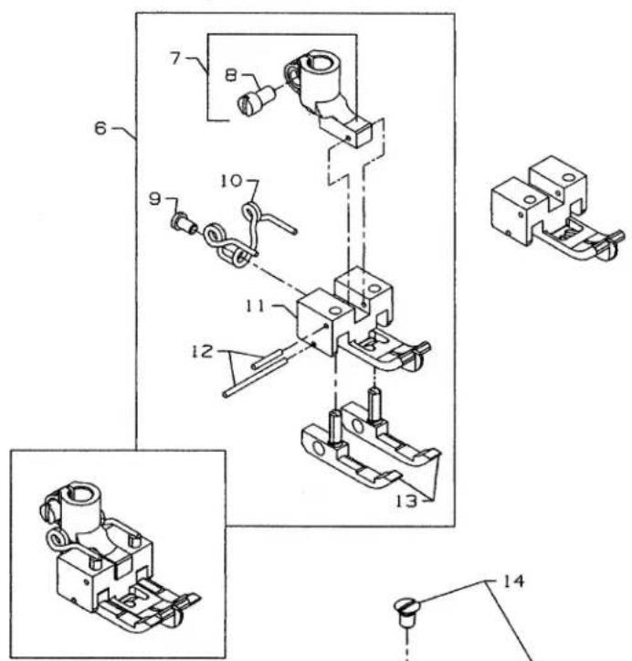
text_image
Technical diagram of a mechanical assembly with numbered components and exploded views
text_image
14 15 15A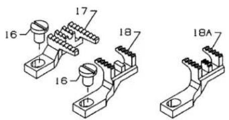
text_image
16 17 18 16 18ASEWING PARTS
FOR CS122K01, CS122K02
CS132K01, CS132K02
Ref.
No. Part No.
Description
Amt.
Req.
- Needle Head, for two needle machines (see chart) 1
1A. ---- Needle Head, for three needle machines (see chart) 1
-
SS6066440TP Screw 1
-
50318AE40 Eyelet, for 4.8 gauge 1
3A. 50318AE56 Eyelet, for 5.6, 6.4 gauges 1
-
SS8080310TP Set Screw 4-6
-
50392G Needle Thread Eyelet 1
-
-
-
-
-
- Presser Foot, for sewing comb., (see chart) 1
-
-
-
-
-
31130A Presser Foot Shank 1
-
91 Screw.... 1
-
605C Screw 1
-
G11940 Spring 1
-
G65-90 Presser Foot Guide 1
-
6-25-55 Drill Rod 2
-
31130RA Yielding Section 2
-
87 Counter Sunk Head Screw, for throat plate 2
-
---- Throat Plate, for two needle machines (see chart) 1
15A. ---- Throat Plate, for three needle machines (see chart) 1
-
99293 Screw, for feed dogs.... 1
-
Main Feed Dog (see chart) 1
-
Differential Feed Dog, for CS122K01, CS132K01 (see chart) 1
18A. Differential Feed Dog, for CS122K02, CS132K02 (see chart) 1
| MODEL | NEEDLE HEAD | PRESSER FOOT ASSEMBLY | THROAT PLATE | FEED DOG MAIN | FEED DOG DIFFERENTAIL |
| CS122K01-2D48 | 50318AN48 | 34727CA48 | 34724CA48 | 34705CA | 34726CA16 |
| CS122K01-2D56 | 50318AN56 | 34727CA60 | 34724CA56 | ||
| CS122K01-2D64 | 50318AN64 | 34724CA64 | |||
| CS122K02-2D56 | 50318AN56 | 34724CB56 | 34726A | ||
| CS122K02-2D64 | 50318AN64 | 34724CB64 | |||
| CS132K01-2D48 | 50318AN48 | 34727CA48 | 34724CA48 | 34726CA16 | |
| CS132K01-2D56 | 58318AN56 | 34727CA60 | 34724CA56 | ||
| CS132K01-2D64 | 50318AN64 | 34724CA64 | |||
| CS132K02-2D56 | 50318AN56 | 34724CB56 | 34726A | ||
| CS132K02-2D64 | 50318AN64 | 34724CB64 |
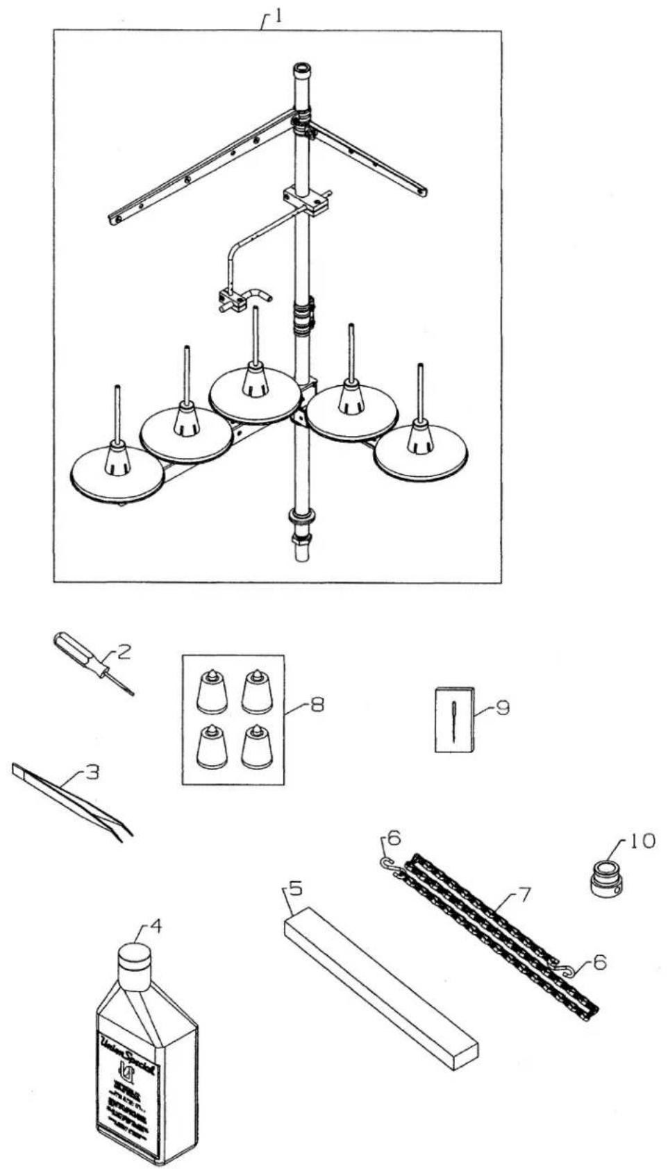
ACCESSORIES
Ref. No. Part No. Description Amt. Req.
- 11969557 Thread Stand (5 cones) 1
- G21201 Screwdriver, for needle head 1
- 12288403 Thread Tweezer 1
- 28604R Oil (1 pint) 1
- 34395 Profile Rubber 1
- 660-264 "S" Hook 2
- 421D42 Chain.... 1
- 51295B Isolator 4
- 121GJS070/027 Needles.... 1
- 34321CC Flange Syncronizer 1
text_image
Technical diagram of a mechanical assembly with numbered components and exploded view, including 3D wireframe views.TAPE GUIDE, HOLD DOWN DEVICE
FOR
CS122E11, CS125E61, CS125E62
CS132E11, CS135E61, CS135E62
Ref.
No. Part No.
Description
Amt.
Req.
-
34786G Tape Guide Assembly 1
-
96275 Retaining Ring 1
-
999-30 "O" Ring 2
-
34786GE Shaft 1
-
34786GA Tape Guide 1
-
34786GB Support 1
-
22894AY Screw 1
-
34783N Support 1
-
22894X Screw 1
-
93A Screw 1
-
34786GC Bracket 1
-
95951 Washer 1
-
999-90B Clamping Lever 1
-
18 Nut 2
-
21657E Washer 1
-
34786GG Roller 1
-
88B Screw 1
-
34786GF Collar 1
-
34731 Hold Down Device Assembly 1
-
34731D Lever 1
-
22570B Screw 1
-
22585C Screw 1
-
34731C Stop 1
-
22836 Screw 1
-
39531B Collar 1
-
604 Screw 1
-
97113 Torsion Spring 1
-
50337BE Material Hold Down Guide 1
-
39531A Shaft 1
-
34731A Hold Down Plate 1
-
77K Screw 2
-
99391 Spacer Stud 1
-
18 Nut 1
text_image
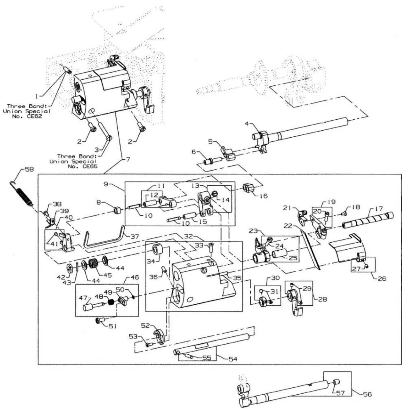
Three Bond: Union Special No. CE62 Three Bond: Union Special No. CE65 58 38 39 40 41 37 9 8 11 12 13 14 10 10 15 16 21 20 19 18 17 42 43 44 45 46 32 33 34 36 35 23 24 25 27 26 30 31 29 28 51 52 53 54 55 57 56UNDER TRIMMER ASSEMBLY
FOR
CS122E11, CS125E61, CS125E62
CS132E11, CS135E61, CS135E62
Amt.
Req.
Ref.
No. Part No.
-
G51347A
-
93
-
22874F
-
50322BH
-
34738A
-
99370
-
29924M
-
34771G
-
34771A
-
666-149
-
34771B
-
G51054
-
34771AA
-
93
-
G51054
-
34771K
-
34785
-
22894BG
-
34771PA
-
22729
-
34770H
-
34749B
-
34750EA
-
22729AB
-
34750A
-
34779
-
22565C
-
34771L
-
88
-
12865
-
88
-
34739N
-
22585R
-
34739A
-
96529
-
51280J
-
1266001
-
77L
-
34771J
-
34771D
-
89
-
99369
-
96530
-
34771E
-
97016
-
34763B
-
34763C
-
97015
-
34763BA
-
660-210
-
22528
-
34771H
-
J87J
-
34771C
-
34771F
-
34734
-
CO67B
-
96722
Description
Screw 1
Screw 2
Screw 1
Shaft 1
Spacer 1
Screw 1
Under Trimmer Assembly 1
Slide Block 1
Lever Assembly 1
Wick 2
Connecting Rod 1
Joint Pin 1
Lever 1
Screw 1
Joint Pin 1
Connection 1
Shaft 1
Screw 1
Upper Knife Lever 1
Screw 1
Upper Knife 1
Lower Knife 1
Knife Holder 1
Screw 1
Bushing 1
Edge Guide 1
Screw 1
Lever 1
Screw 2
Collar 1
Screw 2
Housing 1
Screw 1
Bushing 1
Pin 1
Pin 2
Gasket 1
Screw 1
Stop 1
Lever 1
Screw 1
Nut 1
Pin 1
Spring Washer 2
Spring 1
Locking Plate Assembly 1
Bolt 1
Spring 1
Locking Plate 1
Retaining Ring 1
Screw 1
Stop 1
Screw 1
Shaft 1
Pin....1
Shaft, for feed drive 1
Cork Plug 2
Spring 1


text_image
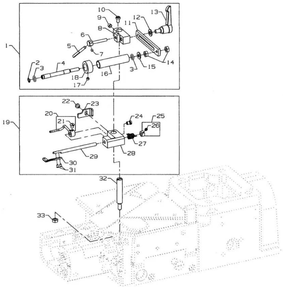
Technical diagram of a mechanical assembly with numbered components and exploded viewPULLER LIFTER ASSEMBLY
FOR
CS125E61, CS125E62, CS125H11, CS125H12,
CS135E61, CS13562, CS135H11, CS135H12
Ref.
No. Part No.
Description
Amt.
Req.
-
50377VA Lever, lifter front 1
-
SS6151440SP Screw 1
-
29476UX Puller Lifter Assembly 1
-
59477 Regulator....1
-
35733G Nut 1
-
660-212 "O" Ring 1
-
50377L Spring 1
-
50377C Lever, lifter 1
-
50344AT Bushing 2
-
50377D Bracket, for roller lifter 1
-
SS8150710SP SetScrew 1
-
SS8120410SP Set Screw 1
-
50337AM Bumper 1
-
50377AF Pin....1
-
96529 Pin....1
-
50377M Lifter 1
-
SS8151150SP Screw 1
-
NS6110310SP Nut 1
-
SS7112420SP Screw 1
-
50377AM Bar, roller presser 1
-
50377AR Guide Pin 1
-
SS6121220TP Screw 2
-
50377T Bushing, lifter link 1
-
RO068190100 "O" Ring 1
-
50377G Lever, puller lifter 1

text_image
Loctite: Union Special No. CE59 Loctite: Union Special No. CE49 18 12 16 14 15 13 17 17 10 9 8 7 6 4 3 2 5 23 24 22 21 25 24 20 23 24 25 22 21 25 20 19PULLER DRIVE ASSEMBLY
FOR
CS125E61, CS125E62, CS125H11, CS125H12,
CS135E61, CS13562, CS135H11, CS135H12
Ref.
No. Part No.
Description
Amt.
Req.
- 29476SP Puller Drive Assembly 1
- 50377F Roller Driving Arm 1
- 660-893 Seal 1
- 50377S Bushing 1
- 50377E Lever, Puller Drive 1
- SS8701042TP Screw 2
- SS8110422TP Set Screw 1
- 50377U Housing, Puller Drive 1
- 50377P Bushing 1
- TA1450404R0 Rubber Plug 1
- SS7121610SP Screw 4
- 50377Z Connecting Rod Eccentric Assembly 1
- 50377AA Connecting Rod.... 1
- SS2090620SP Screw 2
- 50386 Washer 1
- 50377AB Eccentric 1
- SS8660612TP Screw 2
- 50384L Gasket 1
- 50377J Roller Drive Link Assembly 1
- SS6122030SP Screw 2
- 50344AP Bushing, link 2
- 660-303 Bearing 2
- NS6120480SP Nut 2
- WP0501046SC Washer 4
- 660-1089 Thrust Washer 4
text_image
Technical diagram of a mechanical device with numbered components and exploded view, including labeled parts 1 through 10.-
50386E Washer, plastic 2
-
22517 Screw, for lower roller assembly 2
-
22585C Screw 2
-
34380C Roller Guard 1
text_image
Technical diagram of a mechanical assembly with numbered components for identification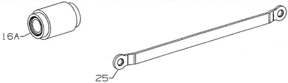
text_image
16A 25text_image
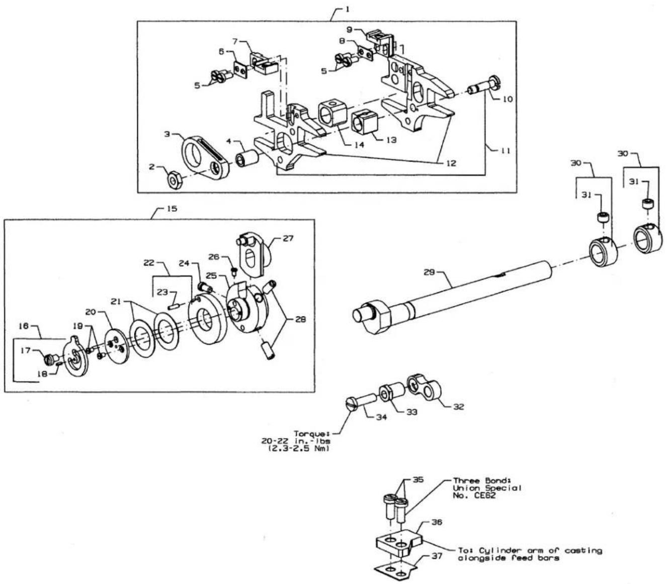
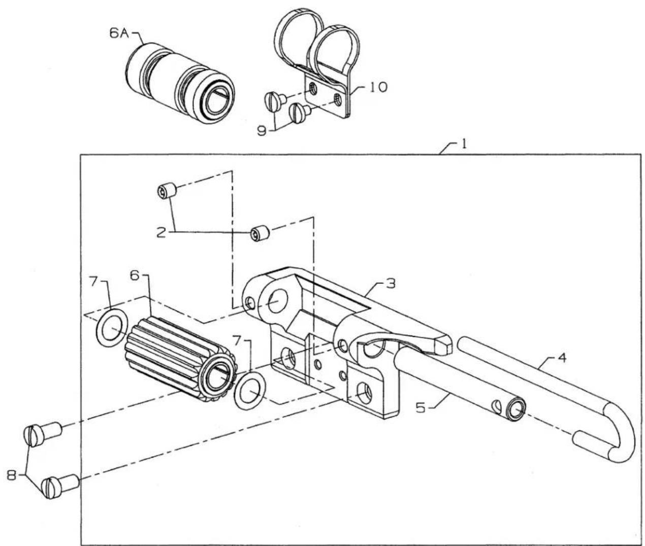
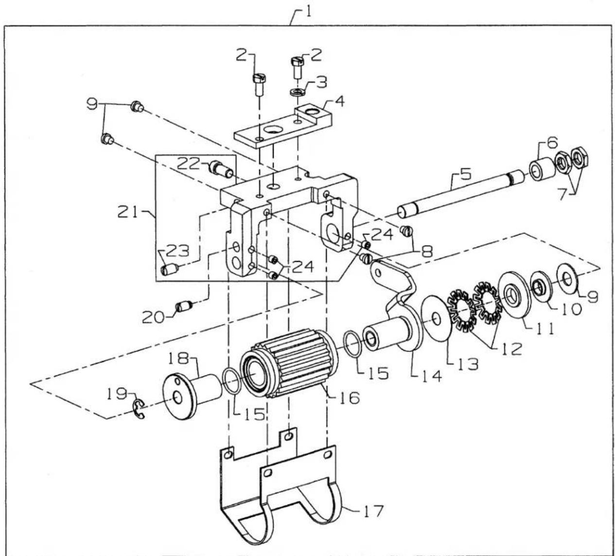
Three Bond: Union Special No. CE62 Screw Into BedFABRIC TRIMMER ASSEMBLY
FOR CS122H21, CS132H21
Ref.
No. Part No.
Description
Amt.
Req.
-
29924LA Fabric Trimmer Assembly 1
-
SS7090530SP Screw 1
-
50372A Knife Lever 1
-
SS7111120TP Screw 1
-
50370J Upper Knife 1
-
34785L Shaft 1
-
34749EL Lower Knife 1
-
50372B Lower Knife Holder 1
-
22729ABA Screw 1
-
34739L Support Block 1
-
22596 Screw 1
-
25CC Screw 1
-
97005D Spring 1
-
33688 Adjusting Collar 1
-
22894AY Screw 2
-
34771SL Lever 1
-
22894C Screw 2
-
34336P Link Pin 1
-
666-149 Oil Wick 1
-
34771VL Lever 1
-
22528 Screw 1
-
9937 Hex Nut 1
-
4611U Washer 1
-
34771UL Adjusting Bolt 1
-
34771TL Connecting Link.... 1
-
22894Y SetScrew 1
-
95412 Screw 2
-
671B115 Suction Tube 1
-
29480AWK Exhaust Assembly 1
-
50396L Guard 1
-
50382JU Sliding Cover, For Guard 1
-
22807 Screw 1
-
98A Screw 1
text_image
Technical diagram of a mechanical assembly with numbered components for identificationNEEDLE DIPPER (EXTRA SEND CHARGE)
Ref.
No. Part No.
Description
Amt.
Req.
- 29480AZV Needle Dipper Assembly 1
- 22562B Screw, for needle dipper 1
- 80265 Washer 1
- 50393GW Felt 1
- 50382KD Needle Dipper Cover 1
- 666-197 Pin, for oil wick 1
- 50393KZ Needle Dipper 1
- CQ20000000 Oil Wick 1
NUMERICAL INDEX OF PARTS
| Part No. | Page No. | Part No. | Page No. | Part No. | Page No. | Part No. | Page No. |
| 11071602 | 21 | 22836 | 59 | 31130RA | 55 | 34381A | 39 |
| 11071701 | 21 | 22874C | 33 | 33688 | 71 | 34381B | 39 |
| 11550209 | 19 | 22874F | 61 | 34306D | 35 | 34382EA | 41 |
| 11638M | 69 | 22875N | 19 | 34321CC | 25, 57 | 34382H | 33 |
| 11969557 | 57 | 22892C | 69 | 34334A | 35 | 34382J | 41 |
| 12124202 | 17 | 22894AD | 9, 31 | 34334S | 33 | 34382UA | 37, 39 |
| 121GJS070/027 | 57 | 22894AD | 35, 67 | 34335 | 35 | 34382V | 37, 39 |
| 12288403 | 57 | 22894AY | 37, 39 | 34335A | 35 | 34382W | 37, 39 |
| 1266001 | 61 | 22894AY | 59, 71 | 34335D | 35 | 34390 | 9 |
| 12865 | 61 | 22894BD | 9, 35 | 34335G | 33 | 34393D | 27 |
| 18 | 59 | 22894BG | 61 | 34335H | 35 | 34393L | 27 |
| 18-1470 | 27 | 22894C | 29, 71 | 34335J | 33, 35 | 34393M | 27 |
| 18C1471 | 17 | 22894T | 31 | 34336A | 33 | 34394A | 9 |
| 18C1475 | 45 | 22894W | 29, 35 | 34336B | 9 | 34394B | 9 |
| 18C1479 | 45 | 22894X | 29, 33 | 34336C | 9 | 34395 | 57 |
| 21657E | 59 | 22894X | 35, 59 | 34336D | 9 | 34642A | 29 |
| 2165D-0.2 | 37, 39 | 22894Y | 71 | 34336E | 9 | 34682C | 27 |
| 22503F | 33 | 258A | 27 | 34336N | 33 | 34703A | 39 |
| 22517 | 67 | 25CC | 71 | 34336P | 35, 71 | 34703B | 39 |
| 22528 | 61, 71 | 25S | 37, 43 | 34336Q | 33 | 34703CA | 39 |
| 22541B | 29, 37 | 28604R | 57 | 34336RA | 33 | 34703F1 | 43 |
| 22541B | 39 | 28B | 35 | 34336S | 33 | 34703F3 | 43 |
| 22548 | 41, 43 | 29105BK | 29 | 34336U | 33 | 34703FA1 | 43 |
| 22561 | 37 | 29126FW | 15 | 34336V | 33 | 34703W2.3 | 47 |
| 22562 | 21 | 29475CG | 17 | 34337 | 35 | 34703W4.3 | 47 |
| 22562A | 33 | 29476SA | 43 | 34337A | 35 | 34703Z | 43 |
| 22562B | 37, 39 | 29476SH | 33 | 34337B | 35 | 34703ZA | 43 |
| 22562B | 73 | 29476SJ | 35 | 34337CA | 35 | 34703ZB | 43 |
| 22565C | 9, 61 | 29476SP | 65 | 34337F | 33 | 34709D | 29 |
| 22569AH | 41 | 29476SS | 69 | 34338 | 33 | 34730A | 49 |
| 22569B | 25 | 29476SW | 67 | 34338B | 33 | 34730AT | 53 |
| 22569C | 43 | 29476TA | 43 | 34340A | 33 | 34731 | 59 |
| 22569G | 35 | 29476TC | 11 | 34342F | 9 | 34731A | 59 |
| 22570B | 59 | 29476TH | 11 | 34342G | 9 | 34731C | 59 |
| 22571E | 27 | 29476TJ | 27 | 34342J | 29 | 34731D | 59 |
| 22571F | 9 | 29476TK | 21 | 34343C | 29 | 34734 | 61 |
| 22580 | 31 | 29476TP | 35 | 34344A | 29 | 34738A | 61 |
| 22585C | 43, 59 | 29476TR | 27 | 34344D | 29 | 34739A | 61 |
| 22585C | 67 | 29476TS | 27 | 34344E | 29 | 34739L | 71 |
| 22585R | 61 | 29476TT | 21 | 34353 | 33 | 34739N | 61 |
| 22652A12 | 29 | 29476TU | 39 | 34353A | 33 | 34749B | 61 |
| 22715A | 43 | 29476TV | 39 | 34358BA | 31 | 34749EL | 71 |
| 22716 | 49, 53 | 29476UA | 31 | 34358CA | 31 | 34750A | 61 |
| 22716A | 47, 53 | 29476UN | 37 | 34358F | 17 | 34750EA | 61 |
| 22729 | 61 | 29476UV | 69 | 34363 | 35 | 34763B | 61 |
| 22729AB | 61 | 29476UX | 63 | 34363A | 35 | 34763BA | 61 |
| 22729ABA | 71 | 29476VK | 29 | 34363B | 35 | 34763C | 61 |
| 22730 | 43 | 29476VL | 27 | 34363C | 35 | 34767 | 67 |
| 22738B | 33 | 29476XT | 35 | 34366 | 31 | 34767K | 43 |
| 22743 | 31 | 29476XU | 67 | 34367 | 37, 39 | 34770H | 61 |
| 22746 | 37, 39 | 29480ARN | 37 | 34367A | 39 | 34771A | 61 |
| 22757E | 43 | 29480AWK | 71 | 34367B | 37, 39 | 34771AA | 61 |
| 22766 | 43 | 29480AYJ | 17 | 34368 | 31 | 34771B | 61 |
| 22768 | 53 | 29480AZV | 73 | 34380 | 39 | 34771C | 61 |
| 22807 | 71 | 29924LA | 71 | 34380B | 67 | 34771D | 61 |
| 22811B | 29 | 29924M | 61 | 34380C | 67 | 34771E | 61 |
| 22829 | 9 | 31130A | 55 | 34380T | 39 | 34771F | 61 |
NUMERICAL INDEX OF PARTS
| Part No. | Page No. | Part No. | Page No. | Part No. | Page No. | Part No. | Page No. |
| 34771G | 61 | 50304M | 31 | 50337AP | 35 | 50358X | 11 |
| 34771H | 61 | 50311C | 25 | 50337AW | 23 | 50360 | 15 |
| 34771J | 61 | 50313T | 29 | 50337BE | 59 | 50360B | 15 |
| 34771K | 61 | 50314G | 29 | 50342AY | 13 | 50360F | 15 |
| 34771L | 61 | 50317B | 11 | 50342BD | 25 | 50360G | 15 |
| 34771PA | 61 | 50317C | 23 | 50342BH | 25 | 50360H | 15 |
| 34771SL | 71 | 50318AE40 | 45, 47 | 50343B | 29 | 50363CK | 17 |
| 34771TL | 71 | 50318AE40 | 49 | 50343C | 29 | 50364R | 43 |
| 34771UL | 71 | 50318AE40 | 53, 55 | 50343RC | 29 | 50364S | 37, 43 |
| 34771VL | 71 | 50318AE56 | 45, 47 | 50344AG | 29 | 50364VB | 43 |
| 34774 | 69 | 50318AE56 | 49 | 50344AP | 65 | 50364X | 37 |
| 34776B | 67 | 50318AE56 | 53, 55 | 50344AR | 25 | 50364Y | 37 |
| 34776F | 67 | 50321J | 25 | 50344AT | 63 | 50364Z | 43 |
| 34778A | 69 | 50321M | 13 | 50344AV | 9 | 50366 | 17 |
| 34778C | 69 | 50322AF | 13 | 50344BK | 9 | 50366A | 17 |
| 34778GD | 37 | 50322AH | 25 | 50344BL | 9 | 50366B | 17 |
| 34778GF | 37 | 50322AN | 25 | 50344BM | 29 | 50366G | 17 |
| 34779 | 61 | 50322AZ | 9 | 50344BN | 9 | 50366J | 17 |
| 34780 | 37 | 50322BB | 13 | 50344BP | 9 | 50366L | 17 |
| 34780CA | 39 | 50322BF | 33 | 50344BU | 9 | 50367S | 35 |
| 34780CB | 39 | 50322BG | 25 | 50345W | 11 | 50367T | 35 |
| 34782C | 41 | 50322BH | 61 | 50346 | 17 | 50370F | 17 |
| 34783N | 59 | 50323P | 11 | 50346A | 15 | 50370J | 71 |
| 34785 | 61 | 50323S | 31 | 50347C | 15 | 50372A | 71 |
| 34785L | 71 | 50325AB | 31 | 50347E | 9 | 50372B | 71 |
| 34786B | 37 | 50325AL | 31 | 50347F | 9 | 50375V | 69 |
| 34786C | 37 | 50325AM | 31 | 50347G | 15 | 50375Y | 69 |
| 34786D | 37 | 50325AN | 31 | 50347J | 15 | 50377AA | 65 |
| 34786G | 59 | 50330BH40 | 49 | 50347L | 9 | 50377AB | 65 |
| 34786GA | 59 | 50330BH64 | 49 | 50347T | 35 | 50377AC | 69 |
| 34786GB | 59 | 50330BL16 | 47 | 50348 | 29 | 50377AD | 69 |
| 34786GC | 59 | 50330CZ | 9 | 50351A | 11 | 50377AE | 69 |
| 34786GE | 59 | 50330DU64 | 53 | 50352 | 11 | 50377AF | 63 |
| 34786GF | 59 | 50330FM40 | 45 | 50354F | 11 | 50377AK | 69 |
| 34786GG | 59 | 50330FM48 | 45 | 50354G | 11 | 50377AM | 63 |
| 34893 | 29 | 50330FM56 | 45 | 50354H | 9 | 50377AR | 63 |
| 35082E | 41 | 50330FN | 45 | 50354J | 9 | 50377AT | 67 |
| 35082F | 41 | 50330FP | 45 | 50355AM | 11 | 50377C | 63 |
| 35733G | 63 | 50330FR | 45 | 50355AN | 11 | 50377D | 63 |
| 36271A | 17 | 50330FS | 45 | 50355AR | 21 | 50377E | 65 |
| 376 | 37 | 50330FU | 45 | 50355AS | 69 | 50377F | 65 |
| 39531A | 59 | 50330GN | 45 | 50357AA | 21 | 50377G | 63 |
| 39531B | 59 | 50330GR | 45 | 50357AG | 31 | 50377H | 69 |
| 39536C | 33 | 50332S | 27 | 50357AH | 31 | 50377J | 65 |
| 39543E | 29 | 50332U | 9 | 50357AJ | 31 | 50377L | 63 |
| 39568J | 49, 53 | 50332V | 21 | 50357AK | 31 | 50377M | 63 |
| 41350X | 27 | 50333H | 31 | 50357AR | 17 | 50377P | 65 |
| 421D42 | 57 | 50333P | 21 | 50357AS | 17 | 50377S | 65 |
| 43281K | 43 | 50335AF | 21 | 50357AT | 17 | 50377T | 63 |
| 4611U | 71 | 50335AG | 21 | 50357AV | 17 | 50377U | 65 |
| 50301BK | 43 | 50335AH | 21 | 50357AW | 17 | 50377VA | 63 |
| 50301BW | 37 | 50335AP | 25 | 50357AX | 17 | 50377Z | 65 |
| 50301BX | 43 | 50335AW | 15 | 50357V | 17 | 50378AD | 69 |
| 50301CP | 41 | 50335BC | 25 | 50357Y | 17 | 50381 | 21 |
| 50302 | 37 | 50335BD | 13 | 50358U | 17 | 50381B | 21 |
| 50302A | 41 | 50335BE | 29 | 50358V | 17 | 50381E | 9 |
| 50302D | 41 | 50337AM | 63 | 50358W | 17 | 50381F | 21 |
NUMERICAL INDEX OF PARTS
| Part No. | Page No. | Part No. | Page No. | Part No. | Page No. | Part No. | Page No. |
| 50381G | 21 | 50393FG | 27 | 61330B41 | 49 | 96275 | 59 |
| 50382FU | 39 | 50393FH | 27 | 61330B42 | 53 | 96276 | 27 |
| 50382FV | 39 | 50393FK | 27 | 61351C | 15 | 96277 | 37, 39 |
| 50382FW | 23 | 50393GB | 27 | 652C16 | 17 | 96278 | 69 |
| 50382FX | 23 | 50393GD | 27 | 660-1014 | 21 | 96529 | 61, 63 |
| 50382FY | 23 | 50393GF | 9 | 660-1043 | 13 | 96530 | 61 |
| 50382FZ | 23 | 50393GT | 27 | 660-1089 | 65 | 96651 | 49, 53 |
| 50382GB | 23 | 50393GU | 27 | 660-210 | 61 | 96663 | 33 |
| 50382GM | 23 | 50393GW | 73 | 660-212 | 23, 27 | 96667 | 33 |
| 50382GR | 43 | 50393HB | 23 | 660-212 | 37, 63 | 96719 | 35 |
| 50382GS | 27 | 50393HE | 27 | 660-264 | 57 | 96722 | 61 |
| 50382GV | 39 | 50393HH | 17 | 660-283A | 19 | 96841 | 9 |
| 50382HU | 37 | 50393HN | 27 | 660-303 | 65 | 96865 | 35 |
| 50382HX | 41 | 50393HS | 11 | 660-739 | 15, 21 | 97005D | 71 |
| 50382JA | 37 | 50393HV | 27 | 660-893 | 65 | 97014 | 37, 39 |
| 50382JL | 23 | 50393JP | 11 | 661-149 | 69 | 97015 | 61 |
| 50382JN | 23 | 50393JW | 11 | 661-252 | 29 | 97016 | 61 |
| 50382JU | 71 | 50393JY | 11 | 661-253 | 29 | 97113 | 59 |
| 50382KD | 73 | 50393JZ | 11 | 661-259B | 11 | 97127 | 37, 43 |
| 50383AD | 23 | 50393KV | 27 | 661-261 | 13, 25 | 97137 | 33 |
| 50383AE | 23 | 50393KW | 9 | 661-261 | 69 | 98A | 17, 71 |
| 50383Y | 35 | 50393KZ | 73 | 661-262 | 13 | 99293 | 45, 47, 49 |
| 50384F | 37, 39 | 50393LA | 27 | 661-348 | 25 | 99293 | 53, 55 |
| 50384L | 23, 65 | 50394AF | 11 | 666-149 | 35, 61 | 99301A | 37, 43 |
| 50386 | 65 | 50395J | 43 | 666-149 | 71 | 99343 | 29 |
| 50386B | 69 | 50395T | 35 | 666-197 | 73 | 99346 | 29 |
| 50386E | 67 | 50395U | 43 | 666-329 | 11 | 99349 | 27 |
| 50386L | 33 | 50396G | 37, 39 | 666-330 | 19 | 99350 | 37, 43 |
| 50386M | 33 | 50396L | 71 | 666-334 | 23 | 99351 | 37, 43 |
| 50389 | 37 | 50397A16 | 47 | 671B115 | 71 | 99352 | 9 |
| 50389A | 37 | 50397A16 | 53 | 671C23 | 37 | 99356 | 37, 43 |
| 50390L | 25 | 50397A48 | 47 | 69H | 37, 39 | 99364L | 37, 39 |
| 50391 | 13 | 50397C | 47, 53 | 77A | 31 | 99369 | 61 |
| 50391A | 13 | 50692G | 19 | 77K | 59 | 9937 | 29, 33, 37 |
| 50392AB | 9 | 51235G | 29 | 77L | 61 | 9937 | 43, 71 |
| 50392AU | 17 | 51280J | 61 | 79 | 39 | 99370 | 61 |
| 50392AV | 19 | 51295B | 57 | 79633 | 47 | 99391 | 59 |
| 50392AW | 17 | 52730Y | 45 | 80265 | 37, 73 | 99392 | 37 |
| 50392AX | 17 | 53678N | 15 | 87 | 45, 47 | 99652A | 29 |
| 50392AY | 17 | 56382D | 41 | 87 | 53, 55 | 99658 | 25 |
| 50392AZ | 17 | 56390E | 25 | 87U | 17 | 99675QA-400 | 37 |
| 50392BC | 19 | 56390H | 29 | 88 | 61 | 99682XC | 23 |
| 50392G | 45, 47 | 56392G | 19 | 88B | 59 | 99682XCB | 23 |
| 50392G | 49 | 56392H | 19 | 89 | 61 | 99697J | 37, 39 |
| 50392G | 53, 55 | 56392M | 19 | 90 | 37, 39 | 999-211 | 9 |
| 50392S | 17 | 56392R | 19 | 91 | 47, 49 | 999-211B | 9 |
| 50392T | 17 | 57830A | 47 | 91 | 53, 55 | 999-211E | 35 |
| 50392W | 19 | 57844 | 17 | 93 | 33, 61 | 999-212-035 | 9 |
| 50392X | 19 | 57865 | 19 | 93A | 59 | 999-215 | 35 |
| 50392Y | 19 | 57892K | 19 | 95 | 43 | 999-254J | 27 |
| 50392Z | 19 | 59477 | 63 | 95205 | 25 | 999-30 | 59 |
| 50393EU | 23, 39 | 6-25-55 | 47, 55 | 95406 | 27 | 999-90B | 59 |
| 50393EW | 23 | 604 | 59 | 95412 | 71 | B3103804000 | 19 |
| 50393EX | 27 | 6042A | 31 | 95685 | 37, 39 | B3112704000 | 19 |
| 50393EZ | 9 | 605 | 47 | 95951 | 59 | B3120352000 | 19 |
| 50393FD | 27 | 605A | 17 | 95953 | 27 | B3120704000 | 19 |
| 50393FE | 27 | 605C | 39, 55 | 96162A | 25 | B3121804000 | 19 |
| 50393FF | 27 | 605D | 39 | 96162B | 15 | B3126012000 | 19 |
NUMERICAL INDEX OF PARTS
| Part No. | Page No. | Part No. | Page No. | Part No. | Page No. |
| B3215470000 ... | 35 | SS1110640SL ... | 23 | SS8150822TP ... | 35 |
| B3530555000 ... | 23 | SS1121010SP ... | 17 | SS8151150SP ... | 63, 69 |
| C50044E ... | 17 | SS2090620SP ... | 65 | SS8660512TP ... | 15, 29 |
| C50056B ... | 21 | SS4080620TP ... | 11, 31 | SS8660612TP ... | 9, 13 |
| C50063N ... | 37, 39 | SS4090515SP ... | 43 | SS8660612TP ... | 15 |
| C50077K ... | 69 | SS4090815SP ... | 17 | SS8660612TP ... | 25, 27 |
| C50094B ... | 27 | SS4120615SP ... | 17, 23 | SS8660612TP ... | 35, 65 |
| CE27 ... | 11 | SS4120615SP ... | 41 | SS8661012TP ... | 13 |
| CE59 ... | 11 | SS4120915SP ... | 17, 19 | SS8681412TP ... | 13 |
| CE63 ... | 11 | SS4120915SP ... | 23 | SS8701042TP ... | 65 |
| CE66 ... | 21 | SS4121215SP ... | 23 | SS9090640SP ... | 15 |
| CO67B ... | 61 | SS4121615SP ... | 23 | SS9111010SP ... | 69 |
| CO67D ... | 29 | SS5060410SP ... | 47, 49 | SS9151740CP ... | 21 |
| CQ200000000 ... | 73 | SS5060410TP ... | 45 | TA1050504R0 ... | 23 |
| CQ25220000 ... | 11 | SS6060440TP ... | 47 | TA1100604R0 ... | 23, 43 |
| G11940 ... | 55 | SS6066440TP ... | 53, 55 | TA1450404R0 ... | 65 |
| G21201 ... | 57 | SS6090420SP ... | 39 | WP0320501SC ... | 31 |
| G29105F ... | 29 | SS6090440SP ... | 11, 31 | WP0501046SC ... | 65 |
| G29476BV ... | 33 | SS6090560TP ... | 29 | WP0742016SP ... | 15 |
| G50-266 ... | 47 | SS6090620SP ... | 11 | WS0371026SD ... | 17 |
| G50-748D ... | 37 | SS6091022TP ... | 29 | WS0510002KP ... | 17, 69 |
| G51054 ... | 35, 61 | SS6110610TP ... | 21 | WZ0641510KP ... | 23 |
| G51347A ... | 61 | SS6121010SP ... | 11, 21 | ||
| G57730GB ... | 49, 53 | SS6121010SP ... | 35 | ||
| G57730GC ... | 49, 53 | SS6121220TP ... | 63 | ||
| G57730GD ... | 49, 53 | SS6122030SP ... | 65 | ||
| G65-134 ... | 47 | SS6151220SP ... | 69 | ||
| G65-90 ... | 55 | SS6151440SP ... | 63 | ||
| GA29477AP ... | 33 | SS6151920SP ... | 21 | ||
| HA20B ... | 29 | SS6153040SP ... | 21 | ||
| HT2C ... | 47 | SS7060310SP ... | 17, 31 | ||
| J79J ... | 39 | SS7080510TP ... | 15, 17 | ||
| J87J ... | 33, 61 | SS7080520SP ... | 11, 31 | ||
| LA451 ... | 23 | SS7090520SP ... | 19 | ||
| NM6030001SD ... | 45 | SS7090530SP ... | 23, 71 | ||
| NS6110310SP ... | 63 | SS7090610SP ... | 17 | ||
| NS6110420SP ... | 19 | SS7090910TP ... | 17 | ||
| NS6120480SP ... | 65 | SS7110410SP ... | 17, 69 | ||
| NS6150310SP ... | 21 | SS7110910TP ... | 15 | ||
| NS6620320SP ... | 23 | SS7111120TP ... | 11, 13 | ||
| NS6680410SP ... | 15 | SS7111120TP ... | 71 | ||
| PH0200063C0 ... | 45 | SS7112420SP ... | 63 | ||
| PH0300164C0 ... | 45 | SS7120640SP ... | 17, 23 | ||
| PH0400104U0 ... | 35 | SS7120710SP ... | 17, 27 | ||
| PS0400142KH ... | 9 | SS7121410TP ... | 15, 19 | ||
| RC0980615K0 ... | 35 | SS7121610SP ... | 65 | ||
| RE0500000K0 ... | 21 | SS7660520SP ... | 13 | ||
| RE0900000K0 ... | 31 | SS7681410TP ... | 13 | ||
| RO037180100 ... | 9 | SS8080310SP ... | 45 | ||
| RO068190100 ... | 21 | SS8080310TP ... | 49, 53 | ||
| RO068190100 ... | 63 | SS8080310TP ... | 55 | ||
| SD0380551SL ... | 17 | SS8080410TP ... | 17 | ||
| SD0640323TP ... | 23 | SS8090540SP ... | 31 | ||
| SD0790303SP ... | 21 | SS8110422TP ... | 11, 15 | ||
| SD1000801SH ... | 15 | SS8110422TP ... | 21, 35 | ||
| SM4030455SP ... | 45 | SS8110422TP ... | 65, 69 | ||
| SM4040655SP ... | 43 | SS8120410SP ... | 63 | ||
| SM7040800SL ... | 45 | SS8150710SP ... | 63 |
NOTES
NOTES
UnionSpecialCorporation
Corporate Office
One Union Special Plaza
Huntley, IL 60142
Phone: 847•669•5101
Fax: 847•669•4454
Union Special GmbH
EuropeanDistributionCenter
Raiffeisenstrasse 3
D-71696 Möglingen, Germany
Tel: 49•07141•247•0
Fax: 49•07141•247•100
JUKI CORPORATION
INTERNATIONAL SALES DIVISION
8-2-1, KOKURYO - CHO,