39500GP - Sewing machine Union Special - Free user manual and instructions
Find the device manual for free 39500GP Union Special in PDF.

| Product Type | Industrial Sewing Machine |
| Brand | Union Special |
| Model | 39500GP |
| Category | Sewing Machine |
| Power Supply | 110-240 V AC, 50/60 Hz |
| Motor Power | 550 W (Clutch Motor) |
| Needle Type | 135x17 or 16x231 |
| Stitch Type | Lockstitch (301) |
| Maximum Sewing Speed | 5000 stitches per minute |
| Maximum Stitch Length | 9 mm |
| Presser Foot Lift | Up to 16 mm |
| Lubrication System | Automatic oiling system |
| Dimensions (L x W x H) | 55 x 25 x 50 cm (approx.) |
| Weight | 35 kg (approx.) |
| Work Area | Flatbed with 40 cm arm reach |
| Material Compatibility | Light to heavy fabrics (denim, canvas, leather) |
| Maintenance | Regular cleaning and oiling as per manual |
| Safety Features | Hand guard, emergency stop button |
| Repairability | Spare parts available through authorized dealers |
| Certification | CE, ISO |
Frequently Asked Questions - 39500GP Union Special
User questions about 39500GP Union Special
0 question about this device. Answer the ones you know or ask your own.
Ask a new question about this device
Download the instructions for your Sewing machine in PDF format for free! Find your manual 39500GP - Union Special and take your electronic device back in hand. On this page are published all the documents necessary for the use of your device. 39500GP by Union Special.
USER MANUAL 39500GP Union Special
natural_image
Pure diagram of a U-shaped object with no text, numbers, or symbolsFINEST QUALITY
STYLES
39500FN
39500FV
39500FX
39500GP
39500GU
39500JX
CATALOG No. 103FN
UnionSpecial®
LEWIS • COLUMBIA
INDUSTRIAL
SEWING
MACHINES
text_image
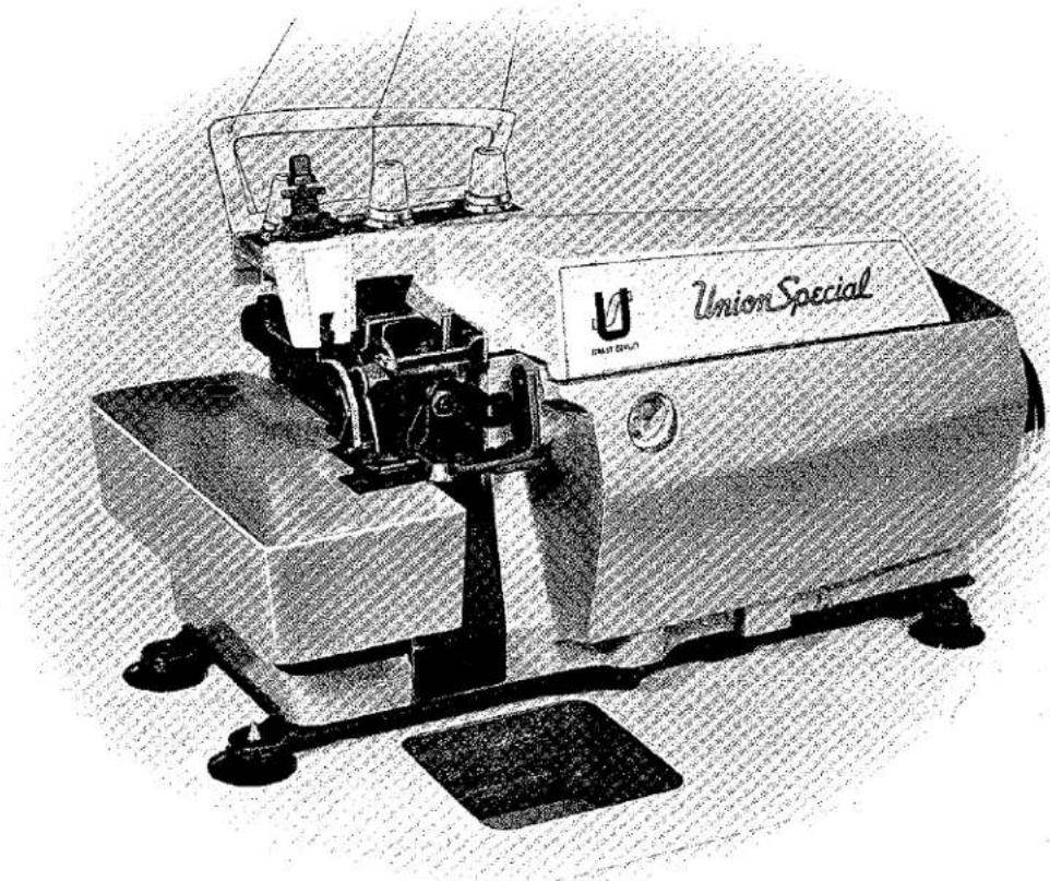
Union SpecialCLASS 39500
HI-STYLED HIGH SPEED THREE THREAD PLAIN FEED OVERSEAMING MACHINES
UnionSpecial MACHINE COMPANY
CHICAGO
Catalog No. 103 FN
(Supplement to Catalog No. 103 FJ)
INSTRUCTIONS
FOR
ADJUSTING AND OPERATING
LIST OF PARTS
CLASS 39500
Styles
39500 FN
39500 FV
39500 FX
39500 GP
39500 GU
39500 JX
First Edition
Copyright 1967
By
Union Special Machine Co.
Rights Reserved in All Countries
UnionSpecial
MACHINE COMPANY
INDUSTRIAL SEWING MACHINES
CHICAGO
Printed in U.S.A.
August, 1967
IDENTIFICATION OF MACHINES
Each Union Special machine is identified by a Style number on a name plate on the machine. Style numbers are classified as standard and special. Standard Style numbers have one or more letters suffixed, but never contain the letter "Z". Example: "Style 39500 FN". Special Style numbers contain the letter "Z". When only minor changes are made in a standard machine, a "Z" is suffixed to the standard Style number. Example: "Style 39500 FNZ".
Styles of machines similar in construction are grouped under a Class number which differs from the Style number in that it contains no letters. Example: "Class 39500".
APPLICATION OF CATALOG
This catalog is a supplement to Catalog No. 103 FJ and should be used in conjunction therewith. Only those parts used on Styles 39500 FN, FV, FX, GP, GU and JX, but not on Style 39500 FJ are illustrated and listed at the back of this catalog. On the page opposite the illustration will be found a listing of the parts with their part numbers, description and the number of pieces required. Numbers in the first column are reference numbers only, and merely indicate the position of that part in the illustration. Reference numbers should never be used in ordering parts. Always use the part number listed in the second column.
This catalog applies specifically to the standard Styles of machines as listed herein. It can also be applied with discretion to some Special Styles of machines in Class 39500. References to directions, such as right, left, front, back, etc., are given from the operator's position while seated at the machine. Operating direction of handwheel is away from operator.
STYLES OF MACHINES
Hi-Styled High Speed Single Curved Blade Needle, Two Looper, Three Thread, Overseaming Machine. Plain Feed, Trimming Mechanism with Spring Pressed Lower Knife, Automatic Lubricating System.
39500 FN Medium to heavy duty machine for overseaming pants, jackets, snow suits, garment pockets and similar operations on medium to heavy weight materials. Seam specification 504-SSa-1; standard seam width 3/16 inch; stitch range 8-20 per inch; cam adjusted feed. Maximum recommended speed 6500 R.P.M.
39500 FV Medium to heavy duty machine for turned edge seaming and straight overedging without cord on rayon bedspreads, bed blankets, towels, wiping cloths and other articles made from fabrics that fray readily. Seam Specification 504-EFe-1 (inverted); standard seam width 3/16 inch; stitch range 7-20 per inch; cam adjusted feed. Maximum recommended speed 6500 R.P.M.
39500 FX Medium to heavy duty machine for simultaneously attaching right pants flies and zipper tapes to pants fronts; also attaching zippers to right flies only and similar operations. Seam specification 504-SSa-1 or SSj-1; standard seam width 3/8 inch; stitch range 6-16 per inch; cam adjusted feed. Maximum recommended speed 6500 R.P.M.
39500 GP Light to medium duty machine for serging and trimming light, medium and heavy weight trousers and similar garments. Seam specification 504-EFd-1; standard seam width 3/16 inch; stitch range 4-10 per inch; cam adjusted feed. Maximum recommended speed 7000 R.P.M.
STYLES OF MACHINES (Continued)
39500 GU Light to medium duty machine for simultaneously attaching zippers with sliders and staples already in place (and overedge the facings) to pants flies, skirts, jackets and similar garments. Seam specification 504-SSa-1; standard seam width 3/16 inch; stitch range 4-10 per inch; cam adjusted feed. Maximum recommended speed 7000 R. P. M.
39500 JX Medium to heavy duty machine for simultaneously attaching right pants flies and zipper tapes to pants fronts of durable press material; also attaching zippers to right flies only and similar operations on durable press material. Seam specification 504-SSa-1 or SSj-1; standard seam width 3/8 inch; stitch range 6-16 per inch; cam adjusted feed. Maximum recommended speed 6500 R.P.M.
OILING
CAUTION! Oil was drained from machine when shipped, so reservoir must be filled before beginning to operate. Oil capacity of Class 39500 is six ounces. A straight mineral oil of a Saybolt viscosity of 200 to 250 seconds at 100^ Fahrenheit should be used.
Machine is filled with oil at spring cap in top cover. Oil level is checked at sight gauge on front of machine. Red bulb on oil level indicator should show between gauge lines when machine is stationary.
Machine is automatically lubricated. No oiling is necessary, other than keeping main reservoir filled. Check oil daily before the morning start; add oil as required.
The drain plug screw is located at back of machine near bottom edge of base. It is a magnetic screw designed to accumulate possible foreign materials which may have entered the crank case. It should be removed and cleaned periodically.
NEEDLES
Each Union Special needle has both type and size number. The type number denotes the kind of shank, point, length, groove, finish and other details. The size number, stamped on the needle shank, denotes largest diameter of blade, measured in thousandths of an inch, midway between shank and eye. Collectively, type and size number represent the complete symbol which is given on the label of all needles packaged and sold by Union Special.
Class 39500 machines use a curved blade needle. The standard recommended needle for the machines covered in this catalog is Type 154 GAS. Below is the description and sizes available of the recommended needle.
Type No.
Description and Sizes
154 GAS Round shank, round point, curved blade, standard length, single groove, struck groove, spotted, chromium plated and is available in sizes 022, 025, 027, 029, 032, 036, 040, 044, 049, 054.
To have needle orders promptly and accurately filled, an empty package, a sample needle, or the type and size number should be forwarded. Use description on label. A complete order would read: "1000 Needles, Type 154 GAS, Size 040".
Selection of proper needle size is determined by size of thread used. Thread should pass freely through needle eye in order to produce a good stitch formation.
NEEDLES (Continued)
Success in the operation of Union Special machines can be secured only by use of needles packaged under our brand name, UnionSpecial which is backed by a reputation for producing highest quality needles in materials and workmanship for more than three-quarters of a century.
CHANGING NEEDLES
Release pressure on presser foot by turning presser foot release bushing (AG) Fig. 1) and swing presser arm (U) out of position. Turn handwheel in operating direction until needle is at its lowest point of travel. Using hexagonal socket wrench No. 21388 AU, furnished with machine, loosen needle clamp nut about 1/4 turn. Again turn handwheel until needle is at high position; withdraw needle.
To replace needle, leave needle holder at high position and, with the flat to the left, insert needle in holder until it rests against stop pin. Keeping needle in this position, turn handwheel until holder is again at its low point of travel; then tighten nut. Return presser arm (U) to position; re-lock presser foot release bushing (AG).
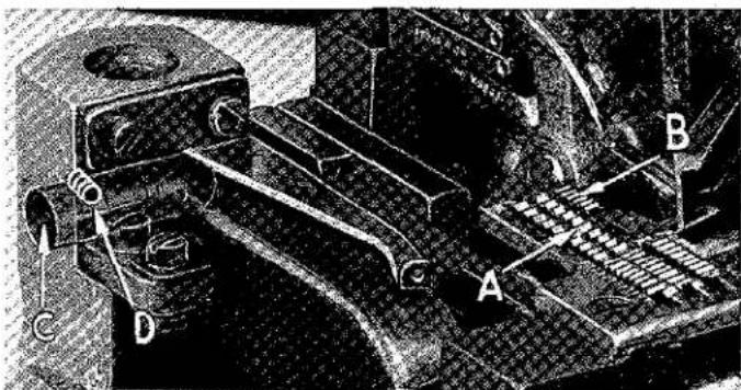
THREAD STAND
After thread comes from cones on cone support (A, Fig. 1), it is brought up through back hole of thread eyelet (B), then down through the front hole of thread eyelet. Next it is threaded through the upper holes of tension thread guide (C) from front to back and then through the lower holes from back to front. It should be noted that the lower looper thread is threaded through the tension thread guide (C), first through the upper hole back to front, second through the middle hole front to back and third through the lower hole back to front. All threads then continue between the tension discs (J), through tension post slot (K) in tension post (G) and on through front thread guide (M).
THREADING
Only parts involved in threading are shown in threading diagram (Fig. 1). Parts are placed in their relative positions for clarity.
It will simplify threading this machine to follow recommended sequence of threading lower looper first, upper looper second, and needle third.
Before beginning to thread, swing cloth plate open, turn handwheel in operating direction until needle (X) is at high position, release pressure on presser foot by turning presser foot release bushing (AG); and swing presser arm (U) out of position.
Be sure threads, as they come from the tension thread guide, are between tension discs (J) and in diagonal slots (K) in tension posts (G).
TO THREAD LOWER LOOPER
Double end of thread and lead it through both eyes of lower looper thread eyelet (R, Fig. 1) from right to left. Note: thread must pass in front of looper thread pull-off (AF). Lead thread behind fabric guard (S) and through eyelet hole of frame looper thread guide (T). Turn handwheel in operating direction until heel of lower looper (V) is all the way to the left; then thread through both eyes from left to right. Left eye of lower looper can be threaded easily if tweezers are in left hand.

text_image
B Thread Eyelet D Tension Nut E Tension Spring Ferrule F Tension Spring G Tension Post H Spring Shield J Tension Discs K Tension Post Slot L Tension Disc Felt Upper Looper To Needle Lower Looper A Cone Support 70° 50° 35° C Tension Thread Guide M Front Thread Guide N Upper Looper Thread Eyelet P Auxiliary Looper Thread Eyelet R Lower Looper Thread Eyelet S Fabric Guard Bracket T Frame Looper Thread Guide U Presser Arm AG Presser Foot Release Bushing AF Looper Thread Pull-off AE Needle Thread Cam Pull-off AD Needle Thread Eyelet AC Top Cover Needle Thread Eyelet AA Upper Looper Thread Tube Assembly X Needle W Upper Looper V Lower LooperFig. 1
TO THREAD UPPER LOOPER
Turn handwheel until point of upper looper (W) is all the way left. Lead thread through auxiliary looper thread eyelet (P) from back to front, then through both eyes of upper looper thread eyelet (N) from left to right. Note: thread must pass in front of looper thread pull-off (AF). After pulling up upper looper thread tube assembly (AA), lead thread under neck of top cover casting and down through thread tube assembly (AA). Pull thread out bottom of tube; push tube down, then insert thread through upper looper eye from front to back.
CAUTION! Be sure upper looper thread is under lower looper thread when passing from tube assembly to upper looper eye.
TO THREAD THE NEEDLE
Turn handwheel in operating direction until needle (X, Fig. 1) is at its highest position. Insert needle thread from right to left, through both eyes of needle thread eyelet (AD), under neck of top cover casting; then down through hole in top cover needle thread eyelet (AC). Thread needle from front.
THREAD TENSION
The amount of tension of needle and looper threads is regulated by three knurled tension nuts (D, Fig. 1). Tension on threads should be only enough to secure proper stitch formation.
PRESSER FOOT PRESSURE
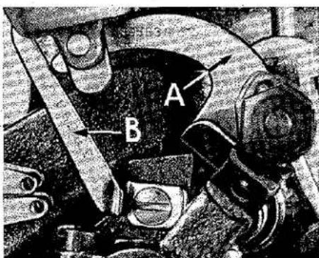
Sufficient presser foot pressure to feed work uniformly should be maintained. Should it be necessary to increase or decrease amount of pressure on presser foot, loosen lock nut (A, Fig. 2) and turn adjusting screw (B). Adjusting screw has a right hand thread so tightening increases pressure, loosening decreases pressure. When pressure adjusting screw (B) has been properly set, tighten lock nut (A). With presser foot resting on throat plate, position locking nut (C) so that its under surface is approximately 1/32 inch to 1/16 inch from the top surface of adjusting screw (B). Set cap (D) against locking nut (C).

natural_image
Two mechanical devices with labeled parts (A, B, C, D) against a textured background, no visible text or symbols.Fig. 2
FEED ECCENTRICS
Feed eccentrics used in these machines have been selected to produce approximately 7 stitches per inch on Styles 39500 GU and JX, 8 stitches per inch on Style 39500 FV, 10 stitches per inch on Styles 39500 GP and FX, and 12 stitches per inch on Style 39500 FN. It will be noted that the part number of the feed eccentric on Style 39500 FN is No. 39540 B-12. Minor number of the part symbol indicates approximately the number of stitches produced when using that eccentric. Unless otherwise specified, machine will be shipped with the eccentric to produce the number of stitches as outlined above.
Following stitch number feed eccentrics are available under No. 39540 B-4, 5, 6,7,8,9,10,11,12,13,14,15,16,18,20,22,24,26,28,30,32,34,36,40. Only two eccentrics are supplied with each machine. Additional eccentrics may be ordered separately. To order an eccentric, use No. 39540 B with a minor number suffixed to indicate number of stitches desired. Example: "39540 B-12".
ASSEMBLING AND ADJUSTING SEWING PARTS
Before assembling and adjusting sewing parts, remove cloth plate, fabric guard, chip guard, upper knife assembly, lower knife holder assembly, then follow this suggested sequence:
SETTING THE NEEDLE
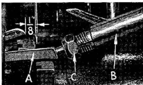
With throat plate assembled in position, needle should center in the front end of needle slot. When needle is at high position, needle point should be set 1/2 inch above throat plate (A, Fig. 3) for Style 39500 FN; 15/32 inch for Styles 39500 FV, FX, GU and JX; and 33/64 inch for Style 39500 GP. To align needle or set the height above the throat plate, move needle driving arm (B, Fig. 3) by loosening clamp screw (C). Remove throat plate.

natural_image
Close-up of a mechanical assembly with labeled parts (B, C, 1/2) and no readable text or symbols beyond labelsFig. 3
If needle thread cam pull-off (A, Fig. 4) overlaps looper thread pull-off (B), separate by moving looper thread pull-off back. When retightening looper pull-off screw, be sure to take up end play in needle driving arm.
text_image
A BFig. 4
At this point, insert lower looper (A, Fig. 5) into bar (B). With lower looper at left end of its stroke, set looper point 1/8 inch from center of needle (Fig. 5), using looper gauge No. 21225-1/8 for Styles 39500 FN, FV, GP and GU. Set looper point 3/32 inch from center of needle (Fig. 5), using looper gauge No. 21225-3/32 for Styles 39500 FX and JX. Do not have lower looper deflecting needle. Tighten nut (C).
Now assemble the main feed dog.
SETTING THE REAR NEEDLE GUARD
Set rear needle guard (A, Fig. 6) as high as possible, without interfering with either lower looper or movement of lower knife holder, but still in position to deflect needle forward .002-.004 inch. Screw (B) is used to set rear needle guard. Make sure there is no interference between rear needle guard and lower looper.
SETTING THE LOWER LOOPER
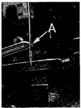
Now finish lower looper adjustment. As lower looper moves to the right, its point should be set into the needle scarf (A, Fig. 7) until the needle springs forward from rear guard surface another .002-.004 inch.
SETTING THE FRONT NEEDLE GUARD
Assemble front needle guard (C, Fig. 6). When lower looper is springing needle off back guard, set front needle guard as close as possible to needle without touching. Screw (D) is used to adjust and set front needle guard. After this setting make sure there is no interference between needle guards and main feed dog.
text_image
1/8 A C BFig. 5
SETTING THE UPPER LOOPER
text_image
A C B DFig. 6
Insert upper looper (A, Fig. 8) in its holder. Screw (B, Fig. 8) holds upper looper in its holder, and permits it to be pushed in or out or turned around its shank. Insert upper looper holder into upper looper shaft, if it is not already in place. Screw (C, Fig. 8) on clamp holds the upper looper holder in the shaft. Locate upper looper in its holder so that the shank extends 1/16 to 3/32 inch beyond holder (Fig. 8), for Styles 39500 FN, FV, FX, GU and JX; 1/32 to 1/16 for Style 39500 GP.
natural_image
Close-up of a mechanical component with an arrow and label 'A' pointing to a feature (no readable text or symbols)Fig. 7
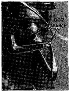
When the upper looper is at the right end of its stroke upper looper holder should be set to position upper looper shank about vertical on Styles 39500 FN, FV, FX and JX (Fig. 8). On Styles 39500 GP and GU the upper looper holder should be set to position the upper looper shank back of vertical. Be sure, on all Styles, there is a clearance between heel of looper and the casting. By adjusting looper holder in or out of upper looper shaft and by turning the looper around its shank, set upper looper point to cross lower looper to the left of the lower looper eye with .002 to .004 clearance (Fig. 9).
As the upper looper moves toward the top of its stroke, the heel of the upper looper should pass behind the lower looper head with 1/32 to 1/16 inch clearance.
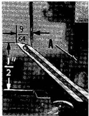
Next, turn handwheel until looper is at the left end of its travel; check dimensions of upper looper point with respect to needle and throat plate (Fig. 10). If resetting is necessary, do it by moving the upper looper holder (A, Fig. 10). Figure 10 represents the dimensional setting for Style 39500 FN.
NOTE: For Styles 39500 FV, FX and JX the setting dimensions are 9/64 and 15/32 inch. For Style 39500 GP the settings are 5/32 and 1/2 inch, and for Style 39500 GU the settings are 5/32 and 29/64 inch. For example, dimension 1/2 inch is increased by turning upper looper holder counterclockwise, looking from left end of machine; dimension 9/64 inch is increased by pulling upper looper holder to the left, out of upper looper shaft. After these changes are made, it may be necessary to turn upper looper around its shank slightly to maintain the condition shown in Fig. 9.

text_image
C B A 1/16 to 3/32Fig. 8
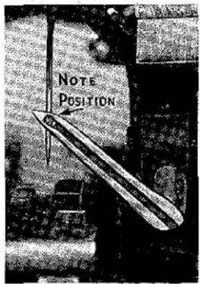
When the correct setting is obtained, it can be checked quickly as follows: As the upper looper is moving to the right and the upper looper eye centers on the needle, the eyes of the upper looper and needle should align exactly (Fig. 11) for Styles 39500 FN, FV, FX, GP and JX. For Style 39500 GU, when the upper looper eye centers on the needle, the bottom of the needle eye should be about level with the top surface of the looper.
Check setting to avoid interference between upper looper and needle on needle downstroke. If needle rubs the back of upper looper, pull looper out of its holder slightly and rotate looper a short distance counterclockwise, looking from left end of machine. Reset to maintain dimensions of Figs. 9, 10, 11.
SETTING THE FEED DOGS
Assemble chaining feed dog to main feed dog (A, B, Fig. 12). Main feed dog should be levelled with respect to the throat plate by rotating feed tilting adjusting pin (C). This pin raises or lowers the back end of the feed bar.
The feed dogs should be set level at the time teeth first appear above the throat plate. Screw (D) locks feed tilting adjusting pin in place. With the feed dogs at their highest point of travel, the top of the teeth on the main feed dog (A) should be 3/64 inch above the throat plate. Now set chaining feed dog teeth (B) flush with the top of throat plate, for Styles 39500 FN, FX, FP, GU and JX. On Style 39500 FV, the chaining feed dog teeth should be set to the same height as the main feed dog teeth.
text_image
002 CLEARANCEFig. 9
SETTING THE LOWER KNIFE
text_image
9 64 A 1/2Fig. 10
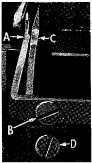
Replace lower knife holder assembly. Lower knife (A, Fig. 13) should be set with cutting edge flush with throat plate surface. Adjustments are made with hexagonal head screw which holds lower knife. Lower knife is spring pressed against upper knife, so no lateral adjustment is necessary when width of trim if changed.
Lower knife may be secured in any position by tightening screw (B) and locking nut (C) against support bracket. Because screw (B) also serves as latch pin for the cloth plate latch spring, it should always be locked with nut (C) even when screw is not tightened against lower knife holder.
text_image
NOTE POSITIONFig. 11
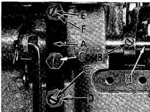
SETTING THE UPPER KNIFE
text_image
Technical diagram of a mechanical assembly with labeled parts A, B, C, D and directional arrows indicating components.Fig. 12
Replace upper knife assembly. Clamp upper knife (D, Fig. 13) in position, setting nut (E) to hold clamp (F) in its most clockwise position against upper knife. At bottom of its stroke, front cutting edge of upper knife should extend not less than 1/64 inch below cutting edge of lower knife. The chain guard (G) should be set down against the upper knife and slightly back from the cutting edge.
After upper knife has been set for proper width of trim, screw (H) should be tightened to lock upper knife holding block (J) in place. This will simplify resetting when upper knife is replaced.
Length of stitch is determined by the feed eccentric used in machine. Note that the part number of the feed eccentric for Styles 39500 GU and JX is No. 39540 B-7; for Style 39500 FV the part number is No. 39540 B-8; for Styles 39500 GP and FX the part number is No. 39540 B-10; and for Style 39500 FN the part number is No. 39540 B-12.
In assembling the feed eccentric (A, Fig. 14), be sure the hub and oil groove is to the left. Beveled edge of feed eccentric spacer (B) should also be to the left side, so the undercut on the spacer will be over the hub on the feed eccentric. Be careful not to damage shaft or key.
Tighten nut (C) securely.
To change feed eccentric, remove nut (C), washer (D) and feed eccentric spacer (B). Turn handwheel in operating direction until key slot in eccentric is toward the front. Using hooked eccentric extractor (E), supplied with machine, reach behind eccentric as shown and withdraw eccentric. It may be necessary to move handwheel back and forth slightly during extraction.
text_image
J E H G F D A C BFig. 13
SETTING THE PRESSER FOOT

text_image
Technical diagram of a mechanical assembly with labeled parts A, B, C, D, and EFig. 14
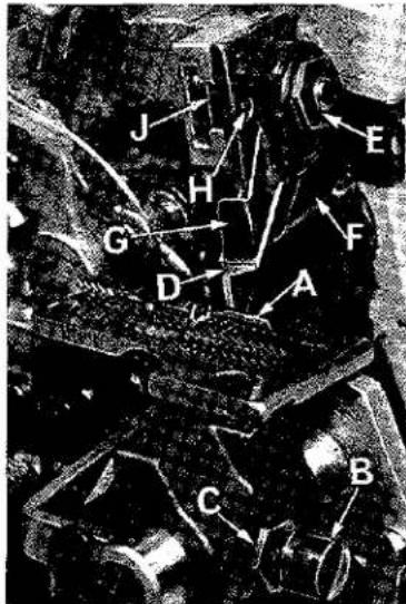
Assemble the presser foot to presser arm. With needle in high position, swing presser arm into sewing position and set the presser foot to align needle holes (front and back) and flat on throat plate. The front edge of needle hole in presser foot must be aligned with front edge of needle hole in throat plate. It is also important that the bottom of the presser foot be flat on the throat plate. If necessary, presser foot can be realigned with throat plate slots by shifting the foot lifter lever shaft (H, Fig. 15). To move the shaft, loosen collar screws (B, Fig. 15) and clamp screw (G) and then shift the foot lifter lever shaft to the left or right as required. Retighten collar screws and clamp screw.
The foot lifter lever arm (A, Fig. 15) and the collar (B) secure the shaft. Be sure the presser arm does not bind and rise when presser foot release bushing is unlocked.
Adjust lifter lever stop screw (C) so that presser foot can be raised no higher than upper looper will permit: then lock the nut (D). There should be from 1/16 to 1/8 inch free motion of foot lifter lever before the presser foot begins to rise. This adjustment should be made with screw (E) and locked with nut (F). Re-assemble the chip guard, fabric guard and cloth plate. To assemble chip guard, turn handwheel until upper knife assembly reaches its highest position.
STARTING TO OPERATE
Be sure machine is threaded according to threading diagram (Fig. 1, page 6). With thread tensions light, set looper thread eyelets (N and R) about horizontal and in the middle of their front to back locations. Operate machine slowly, without presser foot in place, to make sure that chain forms and moves off the tongue freely. Swing presser foot into position, insert material, and sew slowly.
NEEDLE THREAD CONTROL
While sewing on material, check needle thread control as follows: Usually all needle thread is drawn on needle down stroke. At top of needle stroke, thread should be just tight enough to feed chain off stitch tongue. Stitch tends to pull down slightly if excessive thread is pulled on the up stroke. With needle at bottom of stroke, position needle thread eyelet (AD, Fig. 1) so that needle thread cam pull-off (AE) just contacts needle thread.
On all Styles, it is desirable to adjust the needle thread pull-off eyelet well-forward (toward the operator) to delay, slightly, the tightening of the needle thread.
LOWER LOOPER THREAD CONTROL
With material under presser foot, set lower looper thread eyelet (R, Fig. 1) back far enough so thread is a little slack when looper thread pull-off (AF) reaches its most rearward position. Looper thread pull-off (AF) is set about 1/8 inch distance behind needle thread cam pull-off (AE). Frame looper thread guide (T) should be set with its eyelet approximately 1/8 inch to right of lower looper (V) heel eyelet at the time lower looper is at extreme left end of its travel.
text_image
Technical diagram with labeled components A through H, showing directional arrows and geometric shapesFig. 15
While sewing on material, check drawing off of looper thread as follows: A portion of lower looper thread should be drawn through the tension before lower looper thread comes off upper looper. To increase amount of thread drawn through the tension while lower looper thread is on upper looper, move lower looper thread eyelet (R) down, keeping the same amount of pull-off action.
UPPER LOOPER THREAD CONTROL
Before proceeding to adjust upper looper thread eyelet (N, Fig. 1) balance all three tensions to give a normal appearing stitch. Moderate change in these tensions will not markedly effect the purl.
During needle down stroke, forward stroke of looper thread pull-off (AF) will draw upper looper thread through the tension. When normal amount of looper thread is drawn, upper looper thread will have almost all slack taken up as looper thread pull-off reaches its most rearward position.
POSITIONING THE PURL
To move the purl more under the edge, both looper thread eyelets (N and R, Fig. 1) should be raised, keeping the same amount of pull-off. Usually it is better to have slightly more pull-off upper thread than on lower thread.
If it becomes necessary to move looper thread pull-off (AF), be sure to take up all end play in needle drive shaft before tightening. If upper looper is located so that it is higher over throat plate than recommended in Fig. 10, the purl will tend to form near top edge. If upper looper is too low, the purl will form nearer bottom edge.
THREAD TENSIONS
The needle thread tension required is a function of needle thread and material being sewn. In general, lower looper thread tension should be set as high as possible without causing needle thread to be pulled down. Upper looper thread tension should be increased as long as the elasticity of the chain increases, or until the purl is pulled too far over the top.
TERMS
Prices are net cash and subject to change without notice. All shipments are forwarded f.o.b. shipping point. Parcel post shipments are insured unless otherwise directed. A charge is made to cover postage and insurance.
USE GENUINE NEEDLES AND REPAIR PARTS
Success in the operation of these machines can be secured only with genuine Union Special Needles and Repair Parts as furnished by the Union Special Machine Company, its subsidiaries and authorized distributors. They are designed according to the most scientific principles, and are made with utmost precision. Maximum efficiency and durability are assured.
Genuine needles are packaged with labels marked Union Special. Genuine repair parts are stamped with the Union Special trade mark. Each trade mark is your guarantee of the highest quality in materials and workmanship.
IDENTIFYING PARTS
Where the construction permits, each part is stamped with its part number. On some of the smaller parts, and on those where construction does not permit, an identification letter is stamped in to distinguish the part from similar ones.
PART NUMBERS REPRESENT THE SAME PART, REGARDLESS OF CATALOG IN WHICH THEY APPEAR.
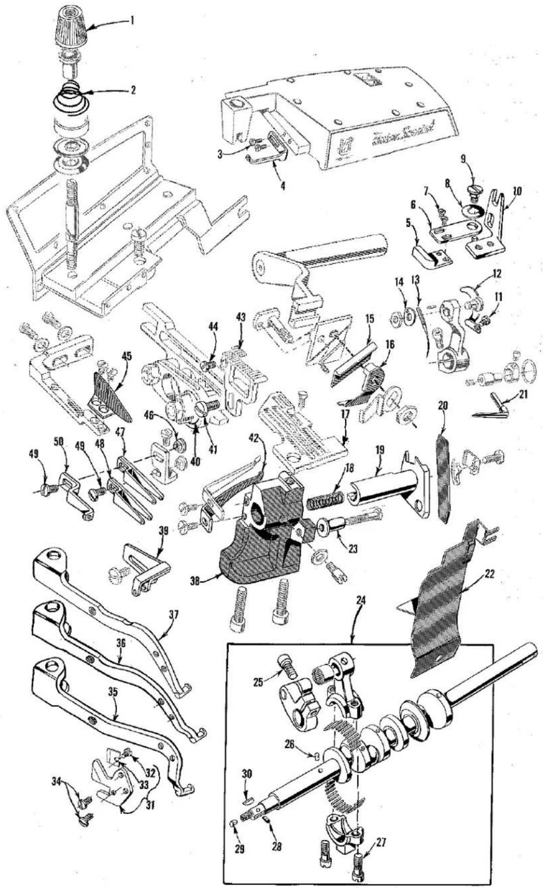
text_image
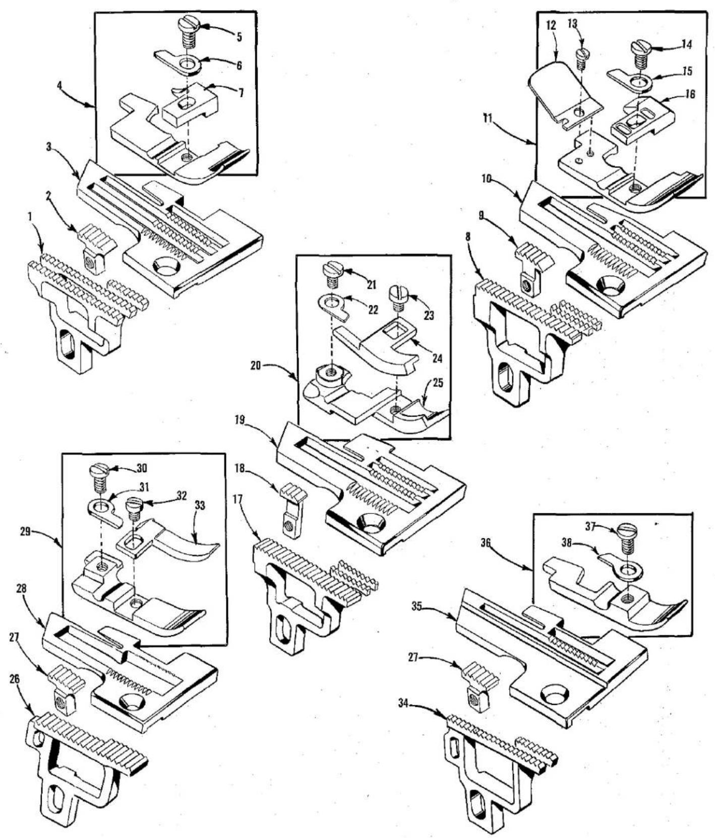
Technical diagram of mechanical assembly with numbered parts, likely a valve or clamp mechanismThe parts illustrated on pages 14 and 16, and described on this page and page 17 represent the parts that are used on Styles 39500 FN, FV, FX, GP, GU and JX, but not used on Style 39500 FJ.
Unless otherwise specified in the description, the parts are used on all the machine styles covered in this catalog. Those parts shown in phantom views and bearing no reference numbers are common to Styles 39500 FJ, FN, FV, FX, GP, GU and JX.
Use Catalog No. 103 FJ (Style 39500 FJ) for all parts not illustrated or described in this catalog.
Reference numbers that are inside a bracket or box on the picture plates and have indented descriptions, indicate they are components of a complete part or assembly.
| Ref.No. | PartNo. | Description | Amt.Req. |
| 1 | 39592 AA | Tension Nut, green, for needle thread | 1 |
| 39592 AB | Tension Nut, blue, for upper looper thread | 1 | |
| 39592 AC | Tension Nut, red, for lower looper thread | 1 | |
| 2 | 39592 AE-4 | Looper Tension Spring, for Styles 39500 FN, FX, GP, GU, JX | 2 |
| 39592 AE-1 | Upper Looper Tension Spring, for Style 39500 FV | 1 | |
| 39592 AE-4 | Lower Looper Tension Spring, for Style 39500 FV | 1 | |
| 39592 AE-8 | Needle Tension Spring, for Styles 39500 FN, FX, GP, GU, JX | 1 | |
| 39592 AE-5 | Needle Tension Spring, for Style 39500 FV | 1 | |
| 3 | 22569 B | Screw, for top cover needle thread eyelet | 2 |
| 4 | 39563 F | Top Cover Needle Thread Eyelet, for Styles 39500 FN, FX, GP, GU, JX | 1 |
| 39563 T | Top Cover Needle Thread Eyelet, for Style 39500 FV | 1 | |
| 5 | 39503 A | Edge Guide, for Styles 39500 FX, GP, JX | 1 |
| 6 | 39503 D | Edge Guide Swinging Arm, for Styles 39500 FX, GP, JX | 1 |
| 7 | 604 | Screw, for edge guide, for Styles 39500 FX, GP, JX | 2 |
| 8 | 12957 E | Washer, for swinging arm, for Styles 39500 FX, GP, JX | 1 |
| 9 | 22758 E | Screw, for swinging arm, for Styles 39500 FX, GP, JX | 1 |
| 10 | 39503 C | Edge Guide Mounting Bracket, for Styles 39500 FX, JP, JX | 1 |
| 11 | 87 U | Screw, for needle thread pull-off cam, for Styles 39500 FN, FV, FX, JX | 1 |
| 77 A | Screw, for needle thread pull-off cam, for Styles 39500 GP, GU | 1 | |
| 12 | 39563 G | Needle Thread Pull-off Cam | 1 |
| 13 | 154 GAS | Needle | 1 |
| 14 | 39551 A | Needle Clamp Washer | 1 |
| 15 | 39570 | Upper Knife, for Style 39500 FN | 1 |
| 16 | 39571 | Upper Knife Clamp, for Style 39500 FN | 1 |
| 17 | Throat Plate (See Page 19) | 1 | |
| 18 | 39550 E | Lower Knife Holder Spring, for Styles 39500 FN, GP, GU | 1 |
| 39550 P | Lower Knife Holder Spring, for Styles 39500 FV, FX, JX | 1 | |
| 19 | 39550 S | Lower Knife Holder, for Styles 39500 FN, FV, FX, GU, JX | 1 |
| 39550 U | Lower Knife Holder, for Style 39500 GP | 1 | |
| 20 | 39549 | Lower Knife | 1 |
| 21 | 39508 A | Upper Looper, marked "CC" | 1 |
| 22 | 39578 U | Chip Guard, for Styles 39500 FN, GP, GU | 1 |
| 39578 TA | Chip Guard, for Styles 39500 FV, FX, JX | 1 | |
| 23 | 39550 C | Lower Knife Locating Stud, for Styles 39500 FN, GP, GU | 1 |
| 39550 R | Lower Knife Locating Stud, for Styles 39500 FV, GP, GU | 1 | |
| 24 | 29477 KE | Crankshaft and Needle Driving Arm Crank Assembly, for Styles 39500 FN, FV, FX, JX | 1 |
| 25 | 22596 E | Screw, for needle driving arm crank | 1 |
| 26 | 51-228 Blk. | Vent Plug | 1 |
| 27 | 22587 J | Screw, for needle driving arm connecting rod | 2 |
| 28 | 30-92 Blk. | Wood Plug | 1 |
| 29 | CO67 E | Cork Plug | 1 |
| 30 | 39541 A | Feed Driving Eccentric Key | 1 |
| 31 | 39556 M | Chain Cutting Knife, for Styles 39500 FX, GP, GU, JX | 1 |
| 32 | 22798 | Screw, for chain cutting blade | 1 |
| 33 | 39556 L | Chain Cutting Blade | 1 |
| 34 | 605 | Screw, for chain cutting knife | 2 |
| 35 | 39556 AU | Presser Arm, for Style 39500 GU | 1 |
| 36 | 39556 D | Presser Arm, for Styles 39500 FX, GP, JX | 1 |
| 39556 F | Presser Arm, for Style 39500 FN | 1 | |
| 37 | 39556 E | Presser Arm, for Style 39500 FV | 1 |
| 38 | 39580 A | Throat Plate Support Bracket, for Styles 39500 FN, FV, FX, GU, JX | 1 |
| 39580 AE | Throat Plate Support Bracket, for Style 39500 GP | 1 | |
| 39 | 39563 H | Needle Thread Eyelet, for Styles 39500 FN, FX, GP, GU, JX | 1 |
| 39563 U | Needle Thread Eyelet, for Style 39500 FV | 1 | |
| 40 | 39540 B-7 | Feed Driving Eccentric, for Styles 39500 GU, JX | 1 |
| 39540 B-8 | Feed Driving Eccentric, for Style 39500 FV | 1 | |
| 39540 B-10 | Feed Driving Eccentric, for Styles 39500 FX, GP | 1 | |
| 39540 B-12 | Feed Driving Eccentric, for Style 39500 FN | 1 | |
| 41 | 22528 | Screw, for main feed dog | 1 |
| 42 | 39525 | Needle Guard, front, for Styles 39500 FN, FV, FX, GU, JX | 1 |
| 39525 L | Needle Guard, front, for Style 39500 GP | 1 | |
| 43 | Feed Dog (See Page 19) | 1 | |
| 44 | 22 KH | Screw, for chaining feed dog, for Styles 39500 FN, FV, FX, JX | 1 |
| 22768 B | Screw, for chaining feed dog, for Styles 39500 GP, GU | 1 | |
| 45 | 39578 M | Fabric Guard, for Styles 39500 GU | 1 |
| 39578 R | Fabric Guard, for Styles 39500 FN, FV, GP | 1 | |
| 39578 S | Fabric Guard, for Styles 39500 FX, JX | 1 | |
| 46 | 43139 A | Nut, for looper thread eyelet screw | 2 |
| 47 | 39568 L | Upper Looper Thread Eyelet, for Styles 39500 FN, FX, GP, GL, JX | 1 |
| 39568 T | Upper Looper Thread Eyelet, for Style 39500 FV | 1 | |
| 48 | 39568 B | Lower Looper Thread Eyelet, for Styles 39500 FN, FX, GP, GL, JX | 1 |
| 39568 S | Lower Looper Thread Eyelet, for Style 39500 FV | 1 | |
| 49 | 376 A | Screw, for looper thread eyelets | 2 |
| 50 | 39568 E | Auxiliary Looper Thread Eyelet, for Styles 39500 FN, FX, GD, GL, JX | 1 |
| 39568 U | Auxiliary Looper Thread Eyelet, for Style 39500 FV | 1 |
text_image
Technical diagram of mechanical assembly with numbered parts, likely a valve or clamp mechanism for assembly or repair.FEED DOGS, THROAT PLATES AND PRESSER FEET
| Ref. No. | Part No. | Description | Amt. Req. |
| 1 | 39505 N | Main Feed Dog, 16 t.p.i., for Style 39500 FN | 1 |
| 2 | 39505 U | Chaining Feed Dog, marked "H", 16 t.p.i., for Style 39500 FN | 1 |
| 3 | 39524 N | Throat Plate, marked "AH-3/16", for Style 39500 FN | 1 |
| 4 | 39520 N | Presser Foot, for Style 39500 FN | 1 |
| 5 | 22768 B | Screw, for stitch tongue and hinge spring | 1 |
| 6 | 39530 | Hinge Spring | 1 |
| 7 | 39597 N | Stitch Tongue, marked "DZ" | 1 |
| 8 | 39505 V | Main Feed Dog, 16 t.p.i., for Style 39500 FV | 1 |
| 9 | 39505 L | Chaining Feed Dog, marked "V", 16 t.p.i., for Style 39500 FV | 1 |
| 10 | 39524 V | Throat Plate, marked "AP", for Style 39500 FV | 1 |
| 11 | 39520 V | Presser Foot, for Style 39500 FV | 1 |
| 12 | 39530 H | Chain Shield | 1 |
| 13 | 22738 | Screw, for chain shield | 1 |
| 14 | 22738 B | Screw, for stitch tongue and hinge spring | 1 |
| 15 | 39530 | Hinge Spring | 1 |
| 16 | 39597 V | Stitch Tongue, marked "ED" | 1 |
| 17 | 39505 X | Main Feed Dog, 16 t.p.i., for Style 39500 FX | 1 |
| 39505 AE | Main Feed Dog, 22 t.p.i., for Style 39500 JX | 1 | |
| 18 | 39505 M | Chaining Feed Dog, marked "Y", 16 t.p.i., for Style 39500 FX | 1 |
| 39505 AF | Chaining Feed Dog, marked "CJ", 22 t.p.i., for Style 39500 JX | 1 | |
| 19 | 39524 X | Throat Plate, marked "AR", for Style 39500 FX | 1 |
| 39528 X | Throat Plate, marked "BM", for Style 39500 JX | 1 | |
| 20 | 39520 X | Presser Foot, for Styles 39500 FX, JX | 1 |
| 21 | 87 U | Screw, for hinge spring | 1 |
| 22 | 39530 | Hinge Spring | 1 |
| 23 | 28 | Screw, for edge guide | 1 |
| 24 | 39530 J | Edge Guide, marked "A" | 1 |
| 25 | 39530 K | Presser Foot Bottom, marked "M" | 1 |
| 26 | 39505 J | Main Feed Dog, 16 t.p.i., for Style 39500 GP | 1 |
| 27 | 39505 K | Chaining Feed Dog, marked "K", 16 t.p.i., for Style 39500 GP, GU | 1 |
| 28 | 39524 J | Throat Plate, for Style 39500 GP | 1 |
| 29 | 39520 L | Presser Foot, for Style 39500 GP | 1 |
| 30 | 22768 B | Screw, for hinge spring | 1 |
| 31 | 39530 | Hinge Spring | 1 |
| 32 | 22819 | Screw, for stitch tongue | 1 |
| 33 | 39597 L | Stitch Tongue, marked "DW" | 1 |
| 34 | 39505 AU | Main Feed Dog, 16 t.p.i., for Style 39500 GU | 1 |
| 35 | 39524 AU | Throat Plate, marked "BG", for Style 39500 GU | 1 |
| 36 | 39520 AU | Presser Foot, for Style 39500 GU | 1 |
| 37 | 22768 B | Screw, for hinge spring | 1 |
| 38 | 39530 G | Hinge Spring | 1 |
Sales Agents For UNION SPECIAL Machines; Also Agent for (L) LEWIS and (C) COLUMBIA where marked.
AFRICA
(TEXTILE & BAG MAKING MACHINES) Berzack Bros., Ltd. REPUBLIC OF SOUTH AFRICA—JOHANNESBURG 135/7 Pritchard St. CAPETOWN—78 Darling St. DURBAN— 72/74 Commercial Road. PORT ELIZABETH—277 Main Street. RHODESIA, BULAWAYO—133 Fife St. SALISBURY —102 Slingo St. (L)
(BAG CLOSING MACHINES) South African Scale Co. Pty., Ltd. REPUBLIC OF SOUTH AFRICA—JOHANNESBURG—32 Von Brandis St. BLOMFONTEIN—53 Zastron St. CAPETOWN—Wales and Bree Sts. DURBAN—22 Allwal St. EAST LONDON—38 Argyle St., LADYSMITH, Natel—355 Murchison. PORT ELIZABETH—Box 611. Also at PIETERMARITZBURG, PRETORIA, VEREENCING and WORCESTER, RHODESIA, BULAWAYO—2 Leander House, Rhodes Street, SALISSURY—95 Victoria Street, ZAMBIA—KITWE-Blantyre Road.
ALGERIA, ALGIERS—Elab. Sayag, B Rue Altairac. ETHIOPIA, ASMARA—S.A. Calderoni Africa, Avenue P. Asfaha Woosen (L & C)
IVORY COAST-ABIDJAN—Ets, Jean Abile-Gal, Box 1798.
KENYA, NAIROBI—Transcandia, Ltd., College House, Koinango St. (P.O. Box 5933) (I & C) (Also Uganda, Tanganyika and Zanzibar)
MALAGASY REPUBLIC—TANANARIVE—Soc. Ind. Et Com. De L'Emyrne, Boite Postale 1078, 17 Rue Clemanceau (L & C)
MAURITIUS, PORT LOUIS—(Bag Closing & Bag Making Machines) Hall, Geneva, Langlois, Ltd., 42 Sir William Newton St.
MOROCCO, CASABLANCA—R. Geissmann & Fils, Rue El Idrissi Es Sakali (L)
NIGERIA, APAPA, LAGOS—Sunflag Knitting Mills (Nigeria) Ltd. 9 Warehouse Road, IL & CI
SUDAN, KHARTOUM—Franco Pinto (Sudan) Ltd., P.O. Box 305. (L & C)
HONG KONG—G. R. Coleman Co. (Hong Kong) Ltd., Rm. 305. Wing Tina Building, 7-13 Wellington St.
INDIA, CALCUTTA—Parrot Sewing Machine (P.) Ltd. 9/1 Savaram Byssack St. (L & C)
JAPAN, QSKA—Kondo Sewing Machine Co. 163, Umegoe-Che Kita-ku. (L) Branch—Tokyo 6-3 Ginza, Chao-Ku. Also at: Arikhon, Fukai, Naroya, Niigata, and Okayama
KOREA, SEOUI—Thehersee-Handel A.G., Rm. 604, Bando Bldg. 180 1-ka Ulchiro; Chung-Ku, Int. P.O. Box 1268. (1) LAOS, VIETIANE—Danis Freres, P.O. Box 133. (C & L) PAKISTAN, (WEST) KARACHI-2—Universal Trading Corp., 29 Zeost Mansion, McLeod Road, (EAST) (Bae closing and bag making machines) Thomas C. Keay, Ltd., 15 Baltic Street, Duades, Scotland.
REPUBLIC OF CHINA, TAIWAN, TAIPEI—G. R. Coleman Co. (Taiwan) Ltd., 16 New Yang St. (L & C).
THAILAND, BANGKOK—Yip In Tsoi & Co., Ltd., P.O. Box 23. (L & C)
VIETNAM, SAIGON—S.A. Pour Le Riz et L'Indutri (Sarl) 147 Trinh Mian-The (B. P. 444) (C & L)
AUSTRALIA
SOLE DISTRIBUTORS: Capron, Carter Pty., Ltd., 86 Liverpool Street, SYDNEY. Branches at: BRISBANE—454 Brunswick St., Valley, N.I. MELBOURNE—154 A'Beckett St. AGENTS: SOUTH AUSTRALIA-ADELAIDE—William Chantick Ltd., London Road, Mile End. WESTERN AUSTRALIA PERTH—Thomsons Pty. Ltd., 789 Hoy St. TASMANIA, LAUNCESTON-Sew Knit Pty. Ltd., 72-74 George St. (L & C)
EUROPE
AUSTRIA, VIENNA—Firma Noeschester, Mariehilfenstr. 51, (L)
BELGIUM, BRUSSELS—Union Special Machine Corporation of America, 90 Rue de la Caserne, Gustavo Thierie, Mgr. (C)
DENMARK, COPENHAGEN—Rothenborg Specialmaskiner for Sy-Industriea A/S, Nikolaj Plods 23. Offices at: AAL-BORG, HERNING, KOLDING, ODENSE, RISSKOV-AARHUS AND SILKESORG. (L & C)
FINLAND, HELSINKI-LAUTASAARI—Suomen Konellike O/Y, Vattuniemenkatu 13. Branches at TAMPERE-Plenteoilisuostale, TURKU, Humallistonkatu 7-B. (L & C)
FRANCE, PARIS—Cle. des Machines Union Special de France, 91 Ave. de la Republique—Thos. de Semlyen, Directeur. Branch at: ROUBAIX (NORD)—50 Ave. J. Lebas. LYON, VILLEURBANNE (RHONE) 58 rue Alexandre Boutin. TOULOUSE (HAUTE GARONNE) 12, 8D. Montaloisir.
GERMANY, STUTTGART—Union Special Moschinenfabrik, G.m.b.H., Schwabstr. 33—A. W. Krieger, Managing Director. Th. M. Boanstra, Director of Sales, BRANCHES AT: BERLIN, BIELEFELD, EBINGEN, FRANKFURT, HAMBURG, KOLN, MUNCHEN, OCHTRUP.
GREAT BRITAIN—(Textile Machinery)—ENGLAND—OADBY (NR. LEICESTER)—Union Special Machine Company, Ltd., Mandervall Road, Industrial Estate, Mr. A. B. Fitzpatrick, Manager, LONDON—108 City Road (H. O. Hall, Manager). SALES OFFICES: BRISTOL, L. J. Heard, 19 The Rides: Kingswood, SCOTLAND, MILNGAVIE (GLASGOW)—Derrick R. Robinson, 48 Clochbor Avenue. SUB-AGENTS: LONDON, W., 1—G. Johnson & Son (Sewing Machinery), Ltd., 58 Great Titchfield Street, MANCHSTER 19—S. A. Smith, (Manchester) Ltd., Park Grove Works, Levansholme. NORTHERN IRELAND—BEFLAST 15, Aklex Ltd. 186 Covehill Road, SCOTLAND, GLASGOW S.E.—Allardice & Co., 9 Stevenson Street. (C) (Bog Closing and Bag Making Machines) SCOTLAND, DUNDEE—Thomas C. Keay, Ltd., 15 Baltic Street—Agent for entire British Isles.
GREECE, ATHENS—Georges Yannakouras-Dimoulis, 30 Petroki St. (L & C)
ICELAND, REYKJAUIK—Magnus Thorgeirsson, Skolavordustig 1a (L & C).
IRELAND, DUBLIN—(Textile Machines) W. Blythman, 224 Parnell Street (L & C) (Bag Closing and Bag Making Machines) Thomas C. Keay, Ltd., 15 Baltic St., Dundee, Scotland.
ITALY, MILANO—Giovanni Conti & Nipoli, Via Varesa 18. (L & C)
MALTA, VALLETTA—A. C. Wismoyer & Co., Ltd., 62 Old Bakery Street, (L & C)
THE NETHERLANDS, AMSTERDAM—N. V. Machinehandel C. & H. Vorbeek, Kioveniersburgwal 77. Oficios at: ARNHEM, ENSCHEDE, GRONINGEN, ROTTERDAM, SITTARD, TILBURG. (L & C)
NORWAY, MANGIERUD—Jac. Jacobsen A/S, Enebakkvelen T17, BERGEN—Bjornsongst 24. (C)
PORTUGAL, OPORTO—Rost & Jonus, Succs. Lda., Rua Barao de Forrester 914. (2)
SPAIN, BARCELONA—Rapido, S.A., Via Layetana 37 (L) SWEDEN, BORAS—Rud. Nystrom & Co., A/B, Lilla Branneregaten 6. Branches at OREBRO-Stoidegatan 37-39, MALMO, S. Forstandsgalan 16. Sub-Agent STOCKHOLM, A/B Forsberg & Kate, Tomtebogatan 38.
Union Special International, Inc.
ARGENTINA, BUENOS AIRES—FROMAC S.A.C., Division Pomaco Costura, S.A., San Jose 350. (Union Special Machine Company), (L & C)
BRAZIL, SAO PAULO—Pancastura S.A.—Industria e Comercio, Rua Aurora 59A.71. Branches at PORTO ALEGRE—Rua Voluntarios da Patria 533; RECIFE—Rua Princesa Isabel 105; RIO DE JANEIRO—Rua Alexandre MacKenzia 117. (C & L)
CHILE, SANTIAGO—Lowenstein & Stewart, S.A.C., Calle Santa Domingo 1140. (L & C)
COLOMBIA, BOGOTA—Macalzade, Ltda., Carrera 30 #12-99. Branches at BARRANQUILLA—Carrera 45-B #34-54. BUCARAMANGA—Calle 34 #17-45. CALI—Carrera 7 #13-33/35. MANIZALES—E. Breslauer, Carrera 22 #18.44. MEDELLIN—Carrera 51, 36-18. PERELRA—Cra. 9—#22-77. (L & C)
COSTA RICA, SAN JOSE—Enrique Rodrigues S., P.O. Box 1949. (L & C)
DOMINICAN REPUBLIC, SANTA DOMINGO—Roberto Domin- quez, G., Calle Dr. Pedro Ureno 19. (L & C)
ECUADOR, GUAYAQUIL—Distribuidoro Richard O. Custer, S.A., Malecon Simon Bolívar #2308. Branch at QUITO—Avegica Patria 768. [L & C]
EL SALVADOR, SAN SALVADOR—Vairo Hermanos, Colo- nig Vairo. (L)
GUATEMALA, GUATEMALA—Compania Agro Comercial, S.A., 8a Avanida Sur Zong I. (L & C)
HONDURAS, SAN PEDRO SULA—Jacoba E. Handel, P.O. Box 559 (L & C)
IRAN, TEHERAN—Sava Trading Corp., Ave. Bozariomehri 881. Serey Sandivah. (L & CI)
IRAQ, BAGHDAD—Sons of O. O. Agopion (IRAQ), P.O. Box 2021, Alwiyah. (L & C)
ISREAL, TEL AVIV—L. Taube, Ltd., 15 Lilienblom St. (L) JORDAN—Bandar & Aroctingi, B.P. 1144—Damas, Syria (L & C)
LEBANON, BEIRUT—Sons of O. O. Agopian, P.O. 1165. (L & C)
SYRIA, DAMAS—Bendar & Aractingl, B.P. 1144. (L & C) TURKEY, ISTANBUL—M. Benmayor, Mahmutpesa Abut Efendi Hon Nr. 46-47. (L & C)
U.A.R., Cairo—Mise Import & Export Co., 6 Rue Adly—Tech. Sub-Agent—A. Kavalidlion. S.A.R.L., 200 Sharia Shuhm. (I & C)
NEW ZEALAND
SOLE DISTRIBUTOR: H. A. Tuck & Co., Ltd., 171 Albert St. AUCKLAND, BRANCH AT: WELLINGTON, Laes Bldg., Nelson St. (L) Also—New Caledonia, Cook Islands, Ellice Islands, Gilbert Islands, New Hebrides, Samoa (American), Tahiti, and Tonga. SUS-AGENTS: Glendermid, Ltd., CHRISTCHURCH—90 Orbell St. DUNEDIN—192-196 Castle St., P.O. Box 40. (C) FIJI SUVA—Karl R. Fleischman, P.O. Box 602. (L) SAMOA (WESTERN), APIA—S. C. Percival, P.O. Box 204. (L)
PACIFIC ISLANDS
HAWAII, HONOLUU—(Textile Machines) Territorial Sales Co., 508 Atkinson Drive. (L). (Bag Closing and Bag Making Machines) H. S. Grey Co., 759 Puglson Rd.
PHILIPPINE ISLANDS, MAKATI, RIZAL—Alkins, Kroll & Co., Inc., 313 Molugay Street, (Buendia Extension). Branch at CEBU. [L & C]
WEST INDIES FEDERATION, JAMAICA
Union Special International, Inc. JAMAICA, KINGSTON—Morris E. Parkin, 96 King St. (L) TRINIDAD, PORT OF SPAIN—Ackrill & Co., 17 Heary St. (L & C) Also—BARBADOS, GRENADA, TOBAGO.
Additional Sales Agents for (L) LEWIS and (C) COLUMBIA Machines 1-44
AUSTRIA IV, VIENNA—Franz Koerpert & Sohne, K.G., Wiedner Hauptstrasse 36. (C)
BELGIUM, BRUSSEL5—N. V. Machinehandel C & H Verbeek, Kruidtuinlaan 57a, Bayl Bldg. (L)
FRANCE, PARIS—Societe G. Amon & Cie., 14 Rue Commines (L)—Aspo-Dumont & Cie., 13 Rue de la Fontaine-Au-Roi. (C)
GERMANY, KREFELD—Herbert Johnson, Alte Linnersstr. 104 (C. tie mach.)
GREAT BRITAIN—ENGLAND, LONDON, E.C.2—Eastman Machine Company, Ltd., 128-132 Curtain Road, CROYDON, 89 Beddington Lane. LEEDS—60 Morrison Street. MANCHESTER, 105-107A Corporation Street, SCOTLAND, GLASGOW 52—11 Drumroach Place, Toryglen. NORTHERN IRELAND, BELFAST 14—W. F. Marwell, 50 Glenbryn Park. REPUBLIC OF IRELAND, DUBLIN—Wm. Blythman, Ltd., 223/4 Parnell Street. (1)
ISRAEL, TEL AVIV—Israel Sewing Machine Co., 22 Yehudo Halevy St. (C)
MEXICO, MEXICO, D.F.—Casa Díaz de Maquinas de Caser, Av. Republic Del Salvador 89-93 (C)
MOROCCO, CASABLANCA—Durkopp Coudrex, 25 Rue Bascu-nana. (C)
NORWAY, OSLO—J. A. Johansen A/S, Tarygatan 10. [L]
REPUBLIC OF SOUTH AFRICA, JOHANNESBURG—African Sewing Machine Company (Pty.) Ltd., 118 President Street, Branches at: CAPE TOWN—110 Plain St.; DURBAN—9 Niew Mlester Lano (C)
RHODESIA, FEDERATION OF RHODESIA & NYASALAND, BULAWAYO—African Sowing Machine Company (Rhodesia) (Pvt.) Ltd., 2 Leonidas House, 138 Rhodes Ave.
SPAIN, BARCELONA—Arbis S/A, Gerona 63. (C)
SWEDEN, BORAS—Husqvaraa, Industrisymaskiner A/B—Katrinedalsgatan 13. Branchos: GOTEBORG—Stigberguliden I MALMO—Isak Stoktaregatan 9—OREBRO—Stortogat 19—STOCKHOLM—Brunnsgatan 6-8. Agents—ULRICENAM—Firma Hjalmar Svensson, Tingshusgatanz. (C)
SWEDEN, BORAS—A/B, A. C. Gustafson, Skolgatan 30, Branches: MALMO—Sevedsgatan 14, STOCKHOLM—Kungsgatan 18 Ulricaham-Holdegatan 20, Sub-Agent—GOTEBORG—Symaskinsverkstaden special, Kungsbejorgatan 7. (L)
SWITZERLAND, ZURICH—Fritz Zellweger & Sohne, Seignaustr. 27. (1., except Button Sewer) Guttinger A.G., Siblistrosse 37. (C)
URUGUAY, MONTEVIDEO—C. Brandes & Cia., S.A., Calle Rincan 658-60. (C)

text_image
DEPENDABLE SERVICE WORLD'S FINEEST QUALITY SINCE 1881UnionSpecial®
INDUSTRIAL SEWING MACHINES
UNION SPECIAL maintains sales and service facilities throughout the world. These offices will aid you in the selection of the right sewing equipment for your particular operation. Union Special representatives and service men are factory trained and are able to serve your needs promptly and efficiently. Whatever your location, there is a Union Special Representative to serve you. Check with him today.
ATLANTA, GA. MONTREAL, QUEBEC
BOSTON, MASS. BRUSSELS, BELGIUM
CHICAGO, ILL. LEICESTER, ENGLAND
DALLAS, TEXAS
LOS ANGELES, CAL.
NEW YORK, N. Y. PARIS, FRANCE
PHILADELPHIA, PA. STUTTGART, GERMANY
Representatives and distributors in all important industrial cities throughout the world.
UnionSpecial
MACHINE COMPANY
400 N. FRANKLIN ST., CHICAGO, ILL. 60610