39500PT - Sewing machine Union Special - Free user manual and instructions
Find the device manual for free 39500PT Union Special in PDF.

User questions about 39500PT Union Special
0 question about this device. Answer the ones you know or ask your own.
Ask a new question about this device
Download the instructions for your Sewing machine in PDF format for free! Find your manual 39500PT - Union Special and take your electronic device back in hand. On this page are published all the documents necessary for the use of your device. 39500PT by Union Special.
USER MANUAL 39500PT Union Special
Adjusting instructions and illustrated parts list
natural_image
Vintage industrial machine with control panel and motor (no visible text or symbols)Class 39500—Differential feed overseamers with thumbscrew adjusted feed travel

text_image
U®Finest Quality
Union Special®
Industrial Sewing Equipment
FOREWORD
This technical manual has been prepared to guide you in the maintenance of your new UNION SPECIAL machine. Careful attention to the instructions for operating and adjusting these machines will enable you to maintain the superior performance and reliability designed and built into every UNION SPECIAL machine.
The Adjusting Instructions portion of this manual explains in detail the proper setting for each of the components related to forming the stitch and completing the functions of the machine. The text of the Adjustments is divided into two sections - Check and Procedure. The Check depicts conditions when the parts are adjusted correctly. The Procedure is given to explain the proper steps to be taken in the event adjustments are required. Figures are used to illustrate the adjustments using reference letters to point out specific items discussed.
Adjustments are presented in sequence so that a logical progression is accomplished. Some adjustments performed out of sequence may have an adverse effect on the function of other related parts.
Implementation of preventative maintenance procedures can bring about significant improvements in operator productivity by avoiding costly equipment breakdowns. Whenever it becomes necessary to make repairs or replace parts on your machine, be sure to insist on genuine UNION SPECIAL Repair Parts. These parts are designed specifically for your machine and manufactured with utmost precision to assure long lasting service.
To simplify identification of repair parts, the mechanisms are illustrated by exploded views. These illustrations will usually be shown in conjunction with a KEY VIEW which presents the mechanisms of the machine assembled. The specific parts illustrated on this page will appear shaded in the KEY VIEW.
Catalog No. 103 PA
For Styles
39500 PA 39500 PP
39500 PE 39500 PT
39500 PF 39500 PW
First Edition
Copyright 1981
By
Union Special Corporation Rights Reserved In All Countries
Printed In U.S.A.
May, 1981
CLASS DESCRIPTION
High Speed, one and two curved needles, two loopers, three and four thread, differential feed overseaming machines. Fabric trimmer with spring pressed lower knife. Independent thumbscrew adjustments for main and differential feed travel. Enclosed automatic lubrication system. Fan cooled.
TECHNICAL DATA
STITCH AND
SEAM TYPE.... 504 SSa-1, Styles 39500 PA, PE, PF, PP, PT 512 SSa-2, Style 39500 PW
FEED SYSTEM..... Independent thumbscrew adjustments for both Main and Differential Feeds.
MAXIMUM SPEED..... 6500 RPM, Styles 39500 PF, PP, PT, PW (Depending on 7000 RPM, Styles 39500 PA, PE Operation)
LUBRICATION..... Enclosed Automatic Splash System with Oil Return Pump
MACHINE STYLES
39500 PA - One needle, low capacity machine for sewing light to mediumweight knit or woven fabrics. Stitch range is 8-20 S.P.I. Typical application - For seaming long straight seams on pajamas and women's underwear. Available Seam Widths: 3/32 inch (2.4mm), 1/8 inch (3.2mm), 5/32 inch (4mm).
39500 PE - Same as 39500 PA except fitted with narrow sewing parts. Typical application - Seaming women's robes and lingerie.
39500 PF - Same as 39500 PA except machine is high capacity for sewing medium to heavyweight knit or woven fabrics. Also equipped with a main feed dog having 16 T.P.I. Stitch range is 8-16 S.P.I.
39500 PP - Same as 39500 PF except equipped with a main feed dog having 12 T.P.I.
39500 PT - Same as 39500 PF except prepared for continuous or intermittent shirring. Maximum shirring ratio is 3 to 1. Available Seam Width: 1/8 inch (3.2mm).
39500 PW - Same as 39500 PP except machine has two needles. Available Seam Width: 17/64 inch (6.7mm).
IDENTIFICATION OF MACHINES
Each UNION SPECIAL machine carries a style number, which on this class machine is stamped in the style plate located to the right rear of the machine.
The serial number is stamped in the extension of casting at the right rear base of machine.
SAFETY RULES

THIS SAFETY SYMBOL INDICATES YOUR PERSONAL SAFETY IS INVOLVED.
TO PREVENT PERSONAL INJURY:
- All power sources to the machine MUST be TURNED OFF before threading, oiling, adjusting or replacing parts.
- Wear safety glasses.
- All shields and guards MUST be in position before operating machine.
- DO NOT tamper with safety shields, guards, etc., while machine is in operation.
LUBRICATION
Oil capacity of Class 39500 is eight ounces (227 milliliters). Use a straight mineral oil with a Saybolt viscosity of 90 to 125 seconds at 100 degrees F. This is equivalent to UNION SPECIAL specification No. 175.
Machine is filled with oil at spring cap in top cover. Before operating, check oil level at sight gauge on front of machine. When proper oil level is reached, red bulb on oil level indicator will register between red gauge lines.
To drain oil remove magnetic plug from back of machine near bottom edge of base. Clean magnetic plug of any metallic material that may have accumulated in crankcase. Oil MUST be changed periodically to minimize wear.
THREADING
Be sure machine is threaded properly according to threading diagram Fig. 1, for Styles 39500 PA, PE, PF, PP, PT, or Fig. 1A, for Style 39500 PW.
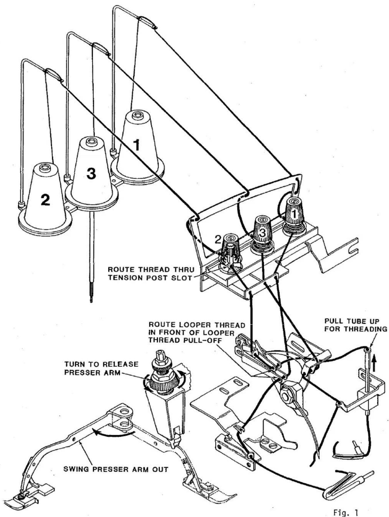
THREADING DIAGRAM STYLES 39500 PA, PE, PF, PP, PT
Before threading machine; unlock presser foot release bushing, swing presser arm and cloth plate out of position and pull upper looper thread tube up. Turn handwheel in operating direction until needle is at highest position. Thread tweezers No. 660-240 are furnished with machine to aid in threading.
Thread machine in sequence as shown; (1) lower looper thread, (2) upper looper thread, (3) needle thread.
THREADING DIAGRAM STYLE 39500 PW
Before threading machine; unlock presser foot release bushing, swing presser arm and cloth plate out of position and pull upper looper thread tube up. Turn handwheel in operating direction until needles are at highest position. Thread tweezers No. 660-240 are furnished with machine to aid in threading.
Thread machine in sequence as shown; (1) lower looper thread, (2) upper looper thread, (3) right needle thread and (4) left needle thread.
text_image
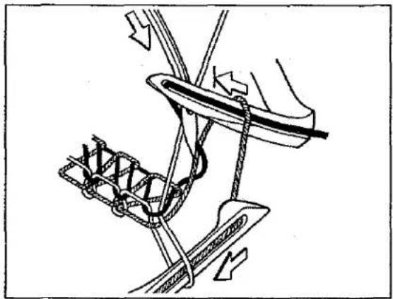
ROUTE THREAD THRU TENSION POST SLOT ROUTE LOOPER THREAD IN FRONT OF LOOPER THREAD PULL-OFF TURN TO RELEASE PRESSER ARM SWING PRESSER ARM OUT PULL TUBE UP FOR THREADING Fig. 1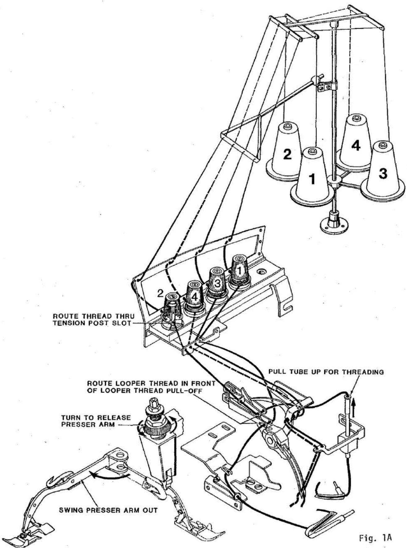
text_image
ROUTE THREAD THRU TENSION POST SLOT ROUTE LOOPER THREAD IN FRONT OF LOOPER THREAD PULL-OFF TURN TO RELEASE PRESSER ARM SWING PRESSER ARM OUT PULL TUBE UP FOR THREADING Fig. 1ANOTE: Instructions stating direction or location, such as right, left, front or rear of machine, are given relative to operator's position at the machine. The handwheel rotates clockwise, in operating direction; when viewed from the right end of machine.
NEEDLES
EXAMINE NEEDLE AND/OR NEEDLES TO ASSURE PROPER TYPE AND SIZE IS BEING USED. THE FOLLOWING CHECKS RELATED TO NEEDLE(S) MUST BE MADE BEFORE ADJUSTING THE NEEDLE(S), LOOPERS OR NEEDLE GUARDS. DISCARD AND REPLACE ANY DEFECTIVE NEEDLE(S).
- Place a new needle of the same type and size alongside the existing needle to check curvature of needle blade as shown (A, Fig. 2).
- Apply the thumbnail test to check for bluntness and/or hooks on the tip of needle(s) as shown (B, Fig. 2).
- Check for any sharpness around eye and/or grooves of needle(s). For a quick check, pull the thread up and down, back and forth through the needle eye as shown (C, Fig. 2). If any sharpness exists, it will shred and severe the thread.
- Be sure needle(s) is all the way up in needle holder and positioned correctly with the spot or scarf to the rear as shown (D, Fig. 2).

text_image
A B C DFig. 2
Machines are sewn off and shipped from the factory with needle(s) listed in chart per machine style:
Machine Style
Type and Size
39500 PA, PE, PF, PP, PT
154 GAS-075/029
39500 PW
154 GAS-090/036
The following chart lists additional needle types and sizes available for Class 39500 machines.
NEEDLE TYPE
DESCRIPTION
SIZES AVAILABLE
154 GAS
Round shank, round point, curved blade, standard length, single groove, struck groove, spotted, chromium plated.
055/022, 065/025, 070/027, 075/029, 080/032, 090/036, 100/040, 110/044, 125/049, 140/054, 150/060
154 GBS
Same as 154 GAS except it has a double groove.
070/027, 075/029, 080/032
| NEEDLE TYPE | DESCRIPTION | SIZES AVAILABLE |
| 154 GES | Same as 154 GAS except it has a shorter blunt point. | 055/022, 065/025, 070/027, 075/029, 080/032, 090/036, 100/040, 110/044, 125/049, 140/054, 150/060 |
| 154 GHS | Same as 154 GAS except it has a ball point. | 065/025, 070/027, 075/029, 080/032, 090/036 |
| 154 GJS | Same as 154 GAS except it has a tapered blade. | 055/022, 065/025, 070/027, 075/029, 080/032, 090/036, 100/040 |
| 154 GLS | Same as 154 GAS except it has a ball eye. | 070/027, 075/029, 080/032, 090/036, 100/040 |
To have needle orders promptly and accurately filled, an empty package, a sample needle or type and size number should be forwarded. Use description on label. A complete order would read "1000 needles, Type 154 GAS, Size 075/029".
text_image
A BFig. 3
NEEDLE REPLACEMENT
Rotate presser foot release bushing counterclockwise and swing presser foot to the left. Turn handwheel in operating direction until needle(s) is at lowest position. Loosen clamp nut using socket wrench No. 21388 AU (A, Fig. 3), then remove needle(s).
Turn handwheel until needle holder (B) is at highest position. Insert new needle(s) all the way up in needle holder with spot or scarf to the rear. Tighten clamp nut, swing presser foot to the right and lock foot into sewing position with presser foot release bushing.
text_image
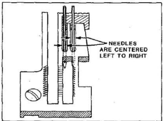
NEEDLES ARE CENTERED LEFT TO RIGHTFig. 4
NEEDLE ALIGNMENT
Check:
Needle(s) must enter the center of needle slot(s) (left to right) in throat plate, as shown in Fig. 4. If adjustment is necessary, remove fabric guard and looper thread pull-off.
Procedure:
Loosen needle driving arm clamp screw (A, Fig. 5) and center needle(s) in needle slot(s) of throat plate by adjusting needle driving arm (B) left to right as required. Temporarily tighten clamp screw (A), then proceed to needle height adjustment.
NEEDLE HEIGHT
Check:
Rotate handwheel in operating direction until needle(s) is at highest position. The needle height measurement from point of needle(s) to top of throat plate must be 1/2 inch (12.7mm) as shown in Fig. 5.

text_image
1/2" (12.7mm)Fig. 5
Procedure:
Loosen clamp screw (A) and adjust needle driving arm (B) front to back as required to obtain needle height shown in Fig. 5, then tighten clamp screw (A) and replace looper thread pull-off.
PRIOR TO MAKING THE FOLLOWING ADJUSTMENT; REMOVE CLOTH PLATE, CHIP GUARD, UPPER KNIFE, MAIN, DIFFERENTIAL AND CHAINING FEEDS. ON MACHINE STYLE 39500 PT REMOVE THE SHIRRING BLADE ASSEMBLY.
CLOTH PLATE
Remove cloth plate (A, Fig. 6) by loosening screw (B) and lifting upward with stud (C) and screw (D) still assembled to plate.
Before replacing cloth plate, hold stud (C) and tighten screw (D) only enough to remove end play, yet allowing cloth plate to swing open when assembled. Assemble cloth plate to machine by inserting stud (C) with flat and "V" notch to the rear into hole of machine bed. Tighten screw (B) to press "V" notch of stud (C) against screw (D).

text_image
Labeled mechanical or laboratory equipment diagram with components A, B, C, and D markedFig. 6

text_image
A 1/8" (3.2 mm) OR 1/16" (1.6mm) BFig. 7
LOWER LOOPER
Check:
PRIOR TO CHECKING LOOPER ADJUSTMENT; REMOVE FRONT AND REAR NEEDLE GUARDS.
LOOPER GAUGE - With looper at extreme left position, 1/8 inch (3.2mm) is the distance between looper point and centerline of needle; 1/16 inch (1.6mm) to left needle on Style 39500 PW, as shown in Fig. 7.
LOOPER CLEARANCE TO NEEDLE(S) - Turn handwheel in operating direction so that looper travels from the extreme left into scarf of needle or
left needle on Style 39500 PW. Point of looper should touch but NOT deflect needle(s).
Procedure:
PRIOR TO ADJUSTING LOOPER, POSITION UPPER LOOPER UP AND AWAY FROM LOWER LOOPER.
Gauge No. 21225-1/8 or 21225-1/16 should be used to properly set looper gauge.
Position lower looper (A) to extreme right and loosen clamp nut (B). Then position looper to extreme left and set looper gauge by adjusting looper in or out of the looper shaft to obtain 1/8 inch (3.2mm) or 1/16 inch (1.6mm) for Style 39500 PW. Rotate handwheel to position looper into scarf of needle or left needle on Style 39500 PW and set looper point to touch but NOT deflect needle(s), then position looper to extreme right and tighten clamp nut (C).

text_image
Technical diagram of a mechanical assembly with labeled components A through F, likely from an engineering or manufacturing context.Fig. 8
REAR NEEDLE GUARD
Remove spring from inside of lower knife holder (A, Fig. 8), then assemble knife holder into throat plate support block.
Replace rear needle guard (B) using screw (C) with front edge of guard centered in slot of knife holder as shown. Temporarily tighten screw (C) to hold guard in position, yet allowing guard to be adjusted.
Rotate handwheel in operating direction so lower looper (D) travels from the extreme left into scarf of needle(s). Set guarding surface of guard (B) to touch but NOT deflect
needle(s) while also setting guard as low as possible to prevent it from interfering with needle thread as loop is being formed to rear of needle(s), then tighten screw (C) securely.
Guard must NOT interfere with lower knife holder movement or contact lower looper at any point of travel.
FRONT NEEDLE GUARD
Replace front needle guard (E, Fig. 8) using screw (F). Temporarily tighten screw (F) to hold guard in position, yet allowing guard to be adjusted.
Rotate handwheel in operating direction until needle(s) is at lowest position, then set guarding surface of guard (E) to needle(s) with minimum clearance - approximately .004 inch (.10mm) and tighten screw (F) securely. Check adjustment to ensure needle(s) is NOT being pinched between front and rear needle guards.
UPPER LOOPER
PROPER ADJUSTMENT OF THE UPPER LOOPER IS ESSENTIAL FOR SUCCESSFUL MACHINE OPERATION. THE PATH TRAVELED BY THE UPPER LOOPER EFFECTS THE MAXIMUM SEAM THICKNESS SEWN.
Rotate handwheel in operating direction and closely observe the path of upper looper as it travels from the extreme right and approaches the lower looper as shown in Fig. 9. The point of upper looper MUST pass the notch in head of lower looper with minimum clearance and pass under lower looper thread.
Again rotate the handwheel until the upper looper is positioned to extreme left as shown in Fig. 10. At this time, point of upper looper MUST be in position so the descending needle or right needle will pass to the right of the upper looper thread, which extends from the eye of the looper to the previously formed stitch. The upper looper must NOT contact the lower looper or needle(s) at any point of travel.

natural_image
Technical line drawing of a mechanical assembly with arrows indicating motion or force direction (no text or symbols)Fig. 9
natural_image
Mechanical diagram showing a lever mechanism with weights and a spring-loaded component (no text or symbols)Fig. 10
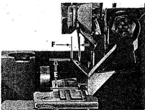
Figures 11, 12, 13 and the following chart relate approximate dimensions for adjusting the upper looper at extreme right and left positions of travel.
| MACHINE STYLE | SHANK EXTENDED ABOVE HOLDER DIM. "D" FIG. 11 | HEIGHT ABOVE THROAT PLATE DIM. "E" FIG. 13 | POINT OF LOOPER TO CENTERLINE OF NEEDLE DIM. "F" FIG. 13 |
| 39500 PA, PE | 1/32 inch (.8mm) | 31/64 inch (12.3mm) | 5/32 inch (4mm) |
| 39500 PF, PP, PT, PW, | 3/32 inch (2.4mm) | 35/64 inch (13.9mm) | 9/64 inch (3.6mm) (right needle on Style PW) |

text_image
Technical diagram of a mechanical assembly with labeled components A, B, C, and DFig. 11
To adjust upper looper, follow instructions listed in sequence as follows:
-
Position upper looper at the left end of travel, loosen clamp screw (A, Fig. 11) and set looper shank to dimension "D" Fig. 11 above holder (B), then temporarily tighten screw (A).
-
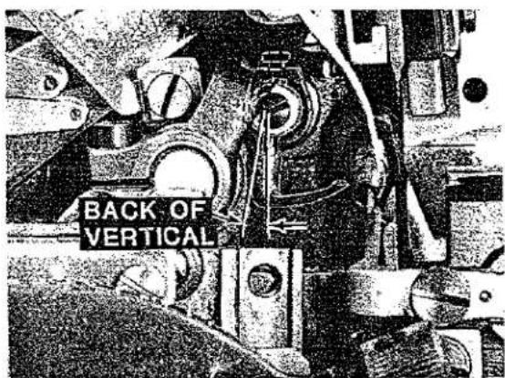
With upper looper positioned at the right end of travel, loosen screw (C) and rotate holder (B) as required to set shank of looper slightly back of vertical, as shown in Fig. 12, then temporarily tighten screw (C, Fig. 11).
-
Rotate handwheel in operating direction bringing the upper looper into the lower looper, See Fig. 9. Loosen screw (A, Fig. 11) and set the point of upper looper to enter the notched area behind head of lower looper with minimum clearance.
-
Again rotate handwheel in operating direction until the upper looper is at the extreme left end of travel. Loosen screw (C, Fig. 11) and rotate upper looper holder as required to set point of upper looper to dimension "E" Fig. 13 from top of throat plate.
-
With upper looper still positioned at the left end of travel, it may be necessary to adjust the looper holder in or out of its shaft to set point of looper to dimension "F" Fig. 13 to the left of needle and/or right needle centerline. Rotate handwheel to position upper looper to the right end of travel, then tighten screw (C, Fig. 11) and screw (A) securely.
-
If the needle(s) is being deflected by the upper looper, clearance to the needle(s) can be increased by reducing the length of looper shank above holder, See Step 1. It will then be necessary to slightly reduce the angle back of vertical, See Step 2. Also reset upper looper to lower looper, See Step 3. Reversing this procedure will position the upper looper closer to the needle(s).
text_image
BACK OF VERTICALFig. 12
text_image
Technical diagram showing a mechanical device with labeled force vectors F and E, likely from an engineering or physics context.Fig. 13
MAIN AND DIFFERENTIAL FEEDS
ASSEMBLE MAIN, DIFFERENTIAL, CHAINING FEEDS AND THROAT PLATE TO MACHINE.
Check:
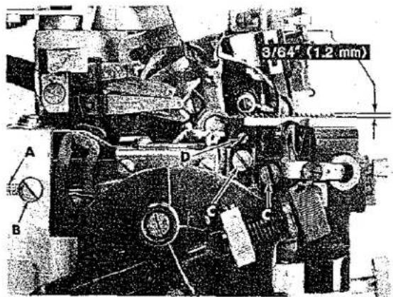
Rotate handwheel in operating direction until teeth of rising feeds are above the top surface of throat plate. The feeds should be level with the throat plate at this time. With feeds at highest position of travel, their teeth should extend approximately 3/64 inch (1.2mm) above throat plate as shown in Fig. 14.
text_image
3/64' (1.2 mm) A B C DFig. 14
Procedure:
Loosen lock screw (A, Fig. 14) and rotate tilt adjusting pin (B) as required to level feeds, then tighten lock screw (A).
Loosen feed attaching screws (C) and adjust feeds up or down to obtain proper height above throat plate as shown in Fig. 14, then tighten screws (C).
On all Styles except 39500 PW; with feeds at highest position, loosen screw (D) and set height of chaining feed even with the stitch tongue of throat plate, then tighten screw (D).
LOWER KNIFE
INSERT SPRING BACK INTO LOWER KNIFE HOLDER AND ASSEMBLE HOLDER TO THROAT PLATE SUPPORT.
Check:
Cutting edge of knife (A, Fig. 15) must be even and parallel with top surface of throat plate. Examine sewn sample for specified seam width and appearance.
Procedure:
Loosen screw (B) and adjust knife (A) up or down until its cutting edge is flush with top of throat plate, then tighten screw (B).
text_image
Technical diagram of a mechanical assembly with labeled components and directional arrows indicating movement or force.Fig. 15
If cutting edge of knife is tilted, loosen screw (C) and rotate holder (D) front to rear as required, then tighten screw (C). Holder MUST move freely, left to right, and NOT bind, with needle guard centered in slot of knife holder.
Adjust knife (A), left to right, by loosening locknut (E), screw (F) and set knife to specified seam width by measuring from center of needle to cutting edge of knife. Hold knife in this position and tighten screw (F). Adjust UPPER KNIFE; then sew-off on a piece of selected material to further check adjustment, by measuring the distance from needle penetration to edge of material. Readjust if necessary, to obtain specified seam width or appearance.
UPPER KNIFE
REMOVE NEEDLE(S) AND RE-ASSEMBLE UPPER KNIFE HOLDER INTO SLOT OF UPPER KNIFE DRIVING ARM. ALSO RE-ASSEMBLE UPPER KNIFE IN HOLDER AND HOLD KNIFE FIRMLY IN POSITION.
Check:
At lowest position the front tip of upper knife cutting edge must extend 1/64 - 1/32 inch (.4 - .8mm) below cutting edge of lower knife.
Procedure:
With upper knife (G, Fig. 15) at lowest position of travel and while holding upper knife firmly against lower knife, adjust knife holder (H) left to right, to position front tip of upper knife cutting edge 1/64 - 1/32 inch (.4 - .8mm) below cutting edge of lower knife, then tighten screw (J).
Assemble knife clamp (K) and chain guard (L) in position using nut (M). Set chain guard (L) against top surface of upper knife and slightly back of its cutting edge, then tighten nut (M).
Loosen screw (F) to enable spring pressed lower knife to move freely left to right. If desired, the lower knife can be locked in position by tightening screw (F) against knife holder.
NOTE: Locking nut (E) must be tightened to hold screw (F) in position; screw (F) also serves as a latch pin for cloth plate.
PRESSER FOOT ALIGNMENT
text_image
A C BFig. 16
LOCK THE PRESSER FOOT IN SEWING POSITION AND ROTATE HANDWHEEL UNTIL NEEDLE(S) IS AT LOWEST POSITION.
Check:
Right edge of presser foot must align with left edge of needle slot in throat plate as shown Ref. Point A, Fig. 16.
Presser foot must lie flat on throat plate. The adjustable stitch tongue on presser foot must center over stitch tongue of throat plate as shown in Fig. 16.
Procedure:
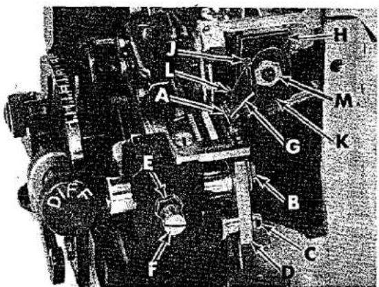
With presser foot locked in sewing position by release bushing (A, Fig. 17), loosen collar screws (B) and clamp screw (C), then adjust lifter lever shaft (D) left to right until the right edge of presser foot aligns with the left edge of needle slot in throat plate as shown Ref. point A, Fig. 16. Tighten collar screws (B, Fig. 17) and while holding lifter lever arm (E) so its stop screw (F) is against intermediate lever (G), tighten clamp screw (C).
Completely unlock release bushing (A, Fig. 17). Plunger should clear presser arm without binding.

text_image
1/16° (1.6mm) N P M L A G F K E B C J H DFig. 17
Loosen screw (B, Fig. 16) and adjust stitch tongue (C) left to right, to center over stitch tongue of throat plate as shown in Fig. 16, then tighten screw (B).
PRESSER FOOT LIFT
Check:
Lift presser foot to highest position and rotate handwheel in operating direction. Upper looper must not contact presser foot at any point of travel.
Procedure:
Loosen locknut (H, Fig. 17) and adjust stop screw (J) so presser foot will not interfere with upper looper, then tighten locknut (H).
Loosen locknut (K) and set stop screw (F) on upper end of lifter lever arm so there is approximately 1/16 inch (1.6mm) free motion in lifter lever before presser foot starts to rise, then tighten locknut (K).
PRESSER FOOT PRESSURE
Check:
Sufficient pressure must be maintained to feed work uniformly. Excessive spring pressure will cause feeds and presser foot to wear prematurely when chaining.
Procedure:
Rotate handwheel in operating direction until both main and differential feeds are positioned below throat plate. Loosen locknut (L, Fig. 17) and turn adjusting screw (M) clockwise for more pressure or counterclockwise for less pressure, then tighten locknut (L).
NOTE: Adjusting screw (M) will effect the function of pressure release bushing (A). Plunger must clear presser arm when pressure release bushing is unlocked. When release bushing is locked in position, presser foot must be held firmly against throat plate. If these conditions do not exist the following adjustment must be made.
Lock presser foot in position with pressure release bushing (A); loosen capnut (N) and adjust nut (P) up or down so its under surface is 1/16 inch (1.6mm) above screw (M) as shown in Fig. 17. Hold nut (M) in position and tighten capnut (N).
text_image
Technical diagram of a mechanical assembly with labeled parts A, B, C, and DFig. 18
SHIRRING BLADE FOR STYLE 39500 PT
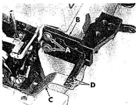
Replace shirring blade assembly. With shirring blade in position, lock presser foot in sewing position and turn handwheel in operating direction until feed dogs are at their highest position. Loosen screws (A, Fig. 18) and adjust shirring blade mounting bracket (B) so the shirring blade (C) is level and lies flat on the feed dog teeth. Position mounting bracket (B) forward or rearward to obtain 1/32 inch (.8mm) clearance between top front edge of shirring blade (C) and the underside of presser foot, then tighten screws (A).
With feed dogs still at their highest position, loosen screws (D) and set shirring blade (C) so its front edge is parallel to the differential feed dog teeth. Hold blade in position and tighten screws (D) maintaining the 1/32 inch (.8mm) clearance between top front edge of shirring blade and underside of presser foot.
text_image
Technical diagram of a mechanical assembly with labeled components A through GFig. 19
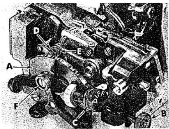
To center shirring blade (C) over differential feed dog, loosen screws in collar (A, Fig. 19), actuating collar (B), operating lever (C) and loosen tension screw (D). Move shaft (E) to the left or right as required to center shirring blade over differential feed dog. While holding blade in position, thrust both collars (A and B) against shaft bracket (F) to eliminate any end play in the shirring blade shaft, then tighten screws in collars (A and B). With the shirring blade properly adjusted and in position, set operating lever (C) in the slot of the shaft bracket and tighten its screw.
Tension on the shirring blade can be obtained by turning shaft collar (G) with spanner
wrench No. 21388 Y, furnished with machine. When the proper amount of tension is obtained, hold shirring blade in position and tighten screw (D).
SETTING STITCH LENGTH
The actual stitch length produced is usually measured as the number of stitches sewn per inch of seam. This is determined by the distance feeds travel with their teeth protruding above the throat plate.
Class 39500 machines are fitted with a feed system having two separate feed dogs - MAIN (rear) and DIFFERENTIAL (front).
The resulting stitch length is determined to a great extent by travel of the main feed. The differential feed travel can be adjusted independent of the main feed and is used to gather or stretch the fabric prior to being stitched.
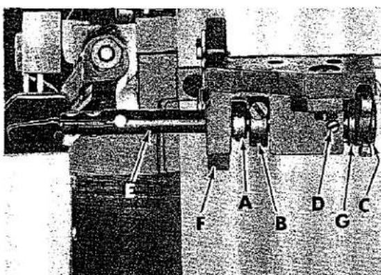
On the graduated scale of indicator plate (A, Fig. 20) the forward marking "L" indicates longest stitch length and the rear marking "S" indicates shortest stitch length.
To adjust stitch length turn both main and differential thumbscrews (B and C) clockwise to increase feed travel or counterclockwise to decrease feed travel.
text_image
Technical diagram of an engine assembly with labeled parts A, B, C, D, E, FFig. 20
After desired stitch length is obtained check the clearance between the main and differential feeds, also check clearance between the throat plate and both feeds. If an adjustment is necessary, set the feeds to have the same travel, then turn the handwheel in operating direction until the differential feed is positioned all the way to the rear. Loosen nut (D) and rotate eccentric ferrule (E) until maximum clearance is obtained. Hold ferrule in position and torque nut to 19-20 in. lbs. (22-23 cm/kg). If clearance cannot be obtained, See FEED DRIVE SEGMENT ADJUSTMENT.
If desired, thumbscrews can be locked in position by tightening nut (F) for the differential feed or by tightening pressure plug screw for the main feed, located in the bed directly above the main feed stitch regulating screw. This will prevent accidental changing of stitch length during machine operation.
NEEDLE THREAD CONTROL
Check:
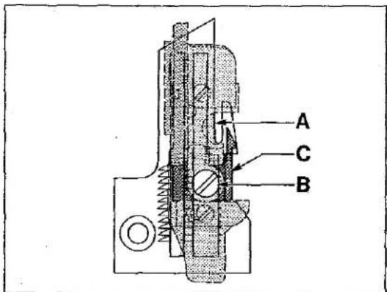
The needle thread is controlled by the needle thread eyelet (A, Fig. 21) and the needle thread cam pull-off (B). The needle thread eyelet is set so the securing screw is centered in the screw slot front to back. Raise or lower the eyelet to have the needle thread barely touch the needle thread cam pull-off when the needle carrier is in its lowest position. Moving the eyelet up and back increases the needle thread in the stitch, moving the eyelet down and forward acts in the reverse.
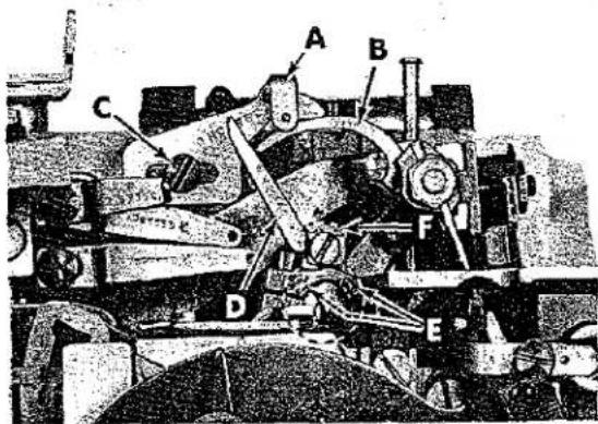
text_image
Technical diagram of a mechanical assembly with labeled parts A, B, C, D, E, FFig. 21
Procedure:
To adjust needle thread control, loosen screw (C) and position thread eyelet (A) as described in check. Hold eyelet in position and tighten screw (C).
LOOPER THREAD PULL-OFF
Check:
Clearance between looper thread pull-off (D, Fig. 21) and needle thread cam pull-off (B) should be only enough to ensure proper take-up of looper thread as shown in Fig. 21.
Procedure:
Loosen screws (E) and rotate looper thread pull-off lever (F) front to back on needle driving shaft until proper clearance is obtained. Before tightening screws (E) be sure to take up all end play in needle drive shaft.
LOOPER THREAD CONTROL
Check:
When a normal amount of looper thread is drawn, upper and lower looper threads will be a little slack when needle(s) is at highest position.
Position guide so the looper thread is held in a straight line to the lower looper, with the lower looper at its extreme left end of travel.
The auxiliary upper looper thread guide should be centered in its adjusting slot and set slightly above a horizontal position.
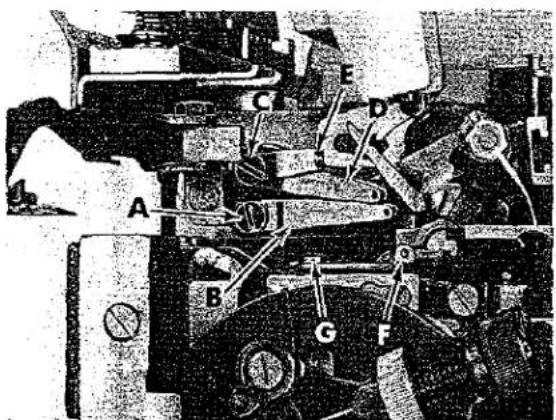
text_image
Technical diagram of a mechanical assembly with labeled parts A through GFig. 22
Procedure:
Loosen screw (A, Fig. 22). Center lower loop-er thread eyelet (B) in its adjusting slot and set eyelet in a horizontal position. Hold eyelet (B) in position and tighten screw (A).
Loosen screw (C). Center upper looper thread eyelet (D) in its adjusting slot and set eyelet so it rests on the top surface of lower looper thread eyelet and back of lower looper thread eyelet eye.
Center auxiliary upper looper thread guide (E) in its adjusting slot and set guide so it is slightly above a horizontal position. Hold
lower looper thread eyelet (D) and auxiliary upper looper thread guide (E) in position and tighten screw (C).
To set frame lower looper thread guide (F) loosen screw (G) and move lower looper to its extreme left end of travel and position the guide so the looper thread is held in a straight line to the lower looper. Tighten screw (G).
NOTE: Moving eyelets (B and D) to the rear increases the amount of looper thread in the system and moving them forward reduces the amount of thread in the system.
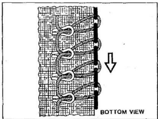
POSITIONING THE PURL
If the needle thread loop is NOT being set properly as shown in Fig. 23, excessive seam grinning would result. Thread control adjustments which should be checked to correct this condition include:
- Lower looper thread tension too tight.
- Needle thread eyelet too high.
- Lower looper thread eyelet too far forward.
- Needle thread tension too loose.
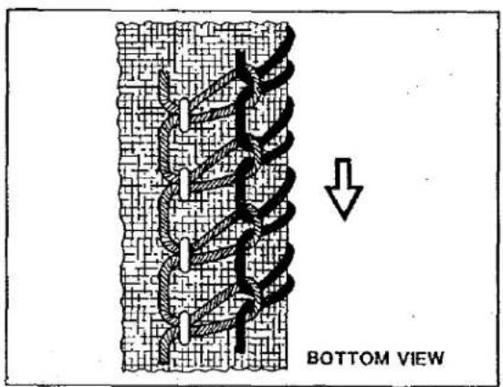
If the purl is NOT being formed on the edge of the fabric as shown in Fig. 24, an unbalance between the looper threads is indicated, and improper coverage of the seamed edge would occur. If the purl is being pulled under the edge, check the following thread control adjustments:
- Lower looper thread too tight.
- Lower looper thread eyelet too far forward.
- Upper looper thread eyelet too far to the rear.
- Upper looper thread tension too loose.
If the purl is being pulled over the edge as shown in Fig. 25, check the following thread control adjustments:
- Upper looper thread tension too tight.
- Upper looper thread eyelet too far forward.
- Lower looper thread eyelet too far to the rear.
- Lower looper thread tension too loose.
text_image
BOTTOM VIEWFig. 23
text_image
BOTTOM VIEWFig. 24

text_image
TOP VIEWFig. 25
THREAD TENSIONS
Thread tension is regulated by the tension assemblies. Turning tension nuts clockwise increases tension applied to thread, counterclockwise reduces tension. Normally, tension on the threads should be only enough to produce a balanced stitch.
text_image
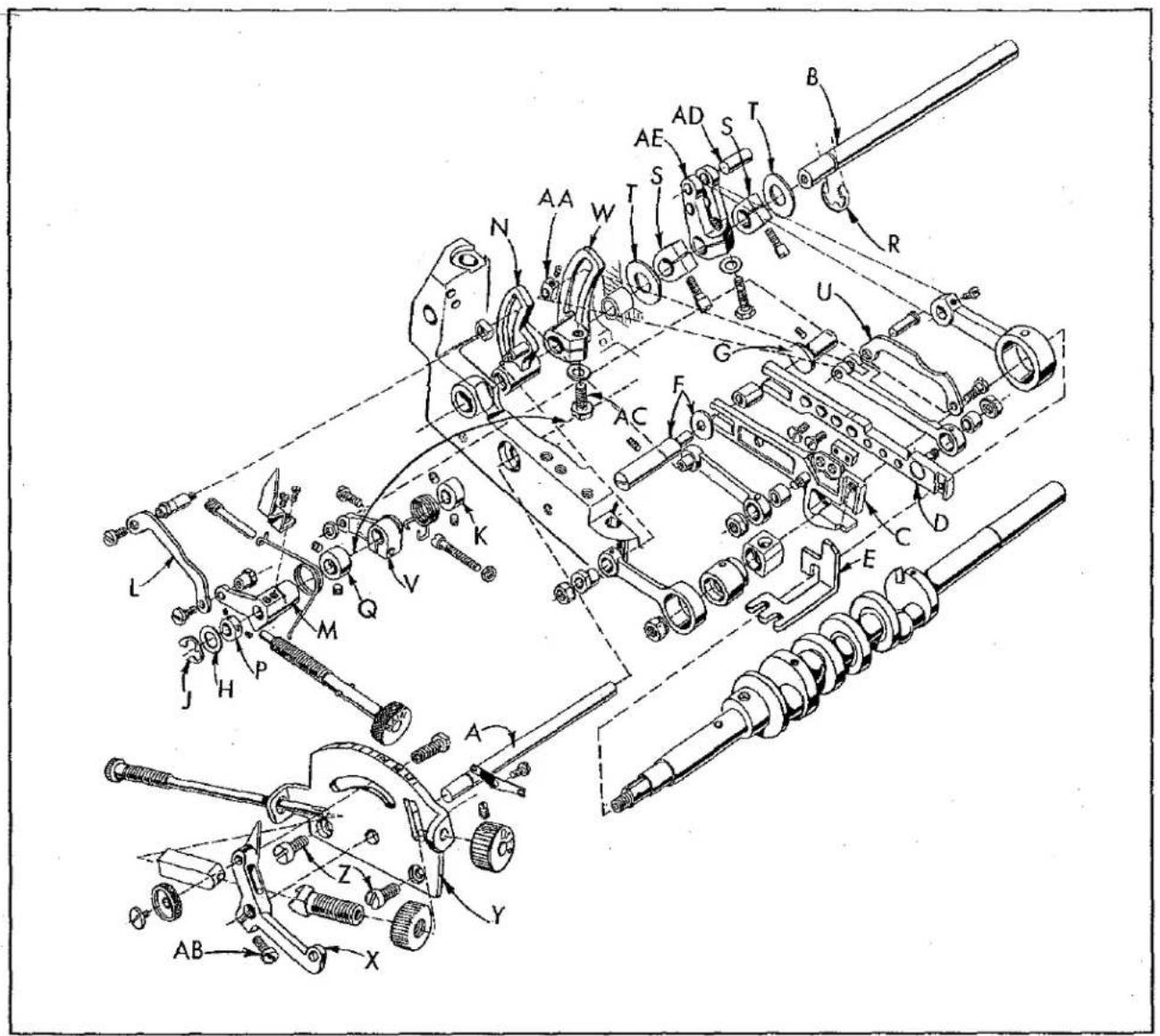
Technical diagram of a mechanical assembly with labeled parts (A-Z) and directional arrows indicating motion or assembly.Fig. 26
ADJUSTING INSTRUCTIONS FOR FEED DRIVE MECHANISM
- Assemble parts as illustrated to feed control shaft (A, Fig. 26) and feed rock shaft (B); including feed bars.
- Thrust feed bars (C and D) against differential thrust guide on bed. Thrust left side of main feed bar (C) with left feed bar thrust guide (E). Align and thrust rear of feed bars with tilt adjusting pin and washer (F) and guide pin (G).
- Thrust the feed control shaft (A) assuring that washer (H) is against retaining ring (J) and flush against the recess in the bed casting. Collar (K) should be thrusted against the bed casting and tightened securely.
-
Main feed control link (L) and main feed drive lever (M) must be in alignment with main feed rocker lever (N) to avoid binding and secured in position by collars (P and Q).
-
Feed rock shaft (B) should be positioned with the opening of the retaining ring (R) upwards and thrusted against the main feed rock lever (N). Secure shaft (B) in this position by thrusting collars (S) against thrust washers (T) against the bed casting.
-
Differential feed control link (U) and differential feed control lever (V) must be in alignment with differential feed rocker lever (W) to avoid binding. Also the differential feed rocker lever (W) must thrust against the main feed rocker lever (N). Lever (V) and rocker lever (W) can be positioned as required and secured in place by their clamp screws.
-
A bind could occur in the main feed drive lever (M), differential feed control lever (V) and differential feed indicator lever (X) if the indicator plate (Y) is not properly aligned. Oversize holes are provided in plate (Y) for its mounting screws (Z) to allow repositioning to eliminate bind.
DIFFERENTIAL FEED CONTROL ADJUSTMENT
-
Move differential rocker lever block (AA) to lowest position in differential feed rocker lever (W).
-
Rotate differential feed indicator lever (X) counterclockwise until the pointer is at the rear end of the scale.
-
Clamp the indicator lever (X) with screw (AB).
DIFFERENTIAL FEED DRIVE SEGMENT ADJUSTMENT
-
Move differential rocker lever block (AA) to top position by rotating lever (X) clockwise.
-
Turn the handwheel until the feed bar is in its most rear position.
-
Loosen feed rocker lever clamp screw (AC).
-
Operate differential feed indicator lever (X) and tighten rocker lever clamp screw (AC) when the differential feed bar (D) shows no movement. Make sure differential feed rocker lever (W) thrusts against the main feed rocker lever (N).
DIFFERENTIAL FEED DRIVE LEVER
Standard location of the drive pin (AD) is to be in the upper hole of differential feed drive lever (AE). For longer differential feed travel move pin (AD) to lower hole of lever (AE).
text_image
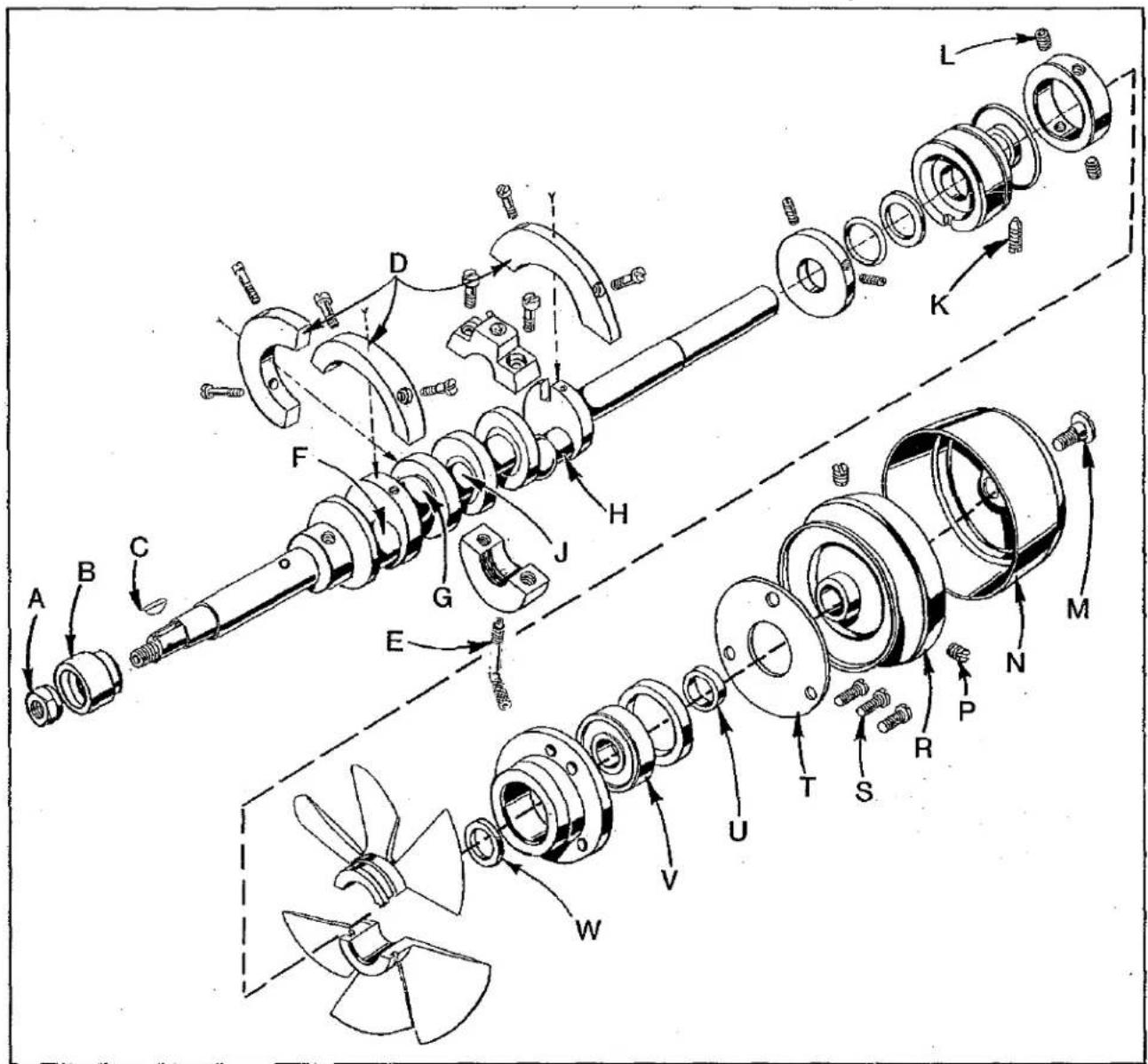
Technical diagram of a mechanical assembly with labeled parts (A–L) and directional arrows indicating motion or assembly.Fig. 27
TO REMOVE CRANKSHAFT
Crankshaft can be withdrawn easier if these steps are followed:
- Drain oil by removing plug screw located on back of machine near bottom edge of base.
- Remove top and bottom covers of machine.
- Remove feed eccentric nut (A, Fig. 27) and remove the eccentric (B).
- Remove key (C).
-
Remove three counterweights (D). Identify these counterweights so that they will be re-assembled in the proper places.
-
Unscrew oil tube (E) which holds crankshaft split bearing and oil pump. This tube is reached through bottom of bed casting.
-
Remove caps of bearings on crankshaft at points F, G and H. When re-assembling bearing caps make sure they are in their original position. Trademarks are stamped on both halves of the caps and both trademarks should be on the same side of the bearings. Also, screws should be re-assembled in the same holes from which they were removed.
-
Loosen clamp nut (A, Fig. 28) which holds upper knife driving arm (B). Access to clamp nut is through top cover. Draw driving arm to the left until upper knife driving lever (C) and connecting rod (D) drop, allowing removal of bearing cap (E). This at bearing point (J, Fig. 27) on crankshaft. Observe same precautions while re-assembling cap as described in Step 7 above.
-
Remove screw (K, Fig. 27) which holds inner right crankshaft bearing. This screw is reached through bottom of bed casting.
-
Loosen two screws (L) in fan collar; remove both halves of cooling fan.
-
Remove screw (M); take off pulley cap (N).
-
Loosen two screws (P); remove pulley (R).
-
Remove three screws (S); take off bearing retaining plate (T); also, spacer collar (U) may be removed at this time.
-
Crankshaft may now be removed:
-
If necessary to replace ball bearing (V), it should be pressed off shaft on an arbor press. In replacing bearing it must be pressed on carefully until it seats against ground thrust washer (W).
-
Carefully observing reverse of the foregoing operations should simplify re-assembly of crankshaft. Checking exploded view drawings for location of various parts and constant testing for binds during re-assembly will also prove helpful.
-
Before re-assembling, thoroughly clean and dry top and bottom covers and gaskets. Before re-assembling bottom cover make sure that spring pressed oil wick which lubricates left crankshaft bearing is inserted in hole in casting and that it contacts shaft. The wick stands vertically on its spring against bottom cover. Coat oil drain plug with a sealing compound before re-assembling to prevent oil leakage.
text_image
Technical diagram of a mechanical assembly with labeled parts A through EFig. 28
ORDERING REPAIR PARTS
ILLUSTRATIONS
This catalog has been arranged to simplify ordering repair parts. Exploded views of various sections of the mechanism are shown so that the parts may be seen in their actual position in the machine. On the page opposite the illustration is a listing of the parts with their part number, description and number of pieces required in the particular view being shown.
Numbers in the first column are reference numbers only, and merely indicate the position of that part in the illustration. Reference numbers should never be used in ordering parts. Always use the part number which is listed in the second column.
Component parts of sub-assemblies which can be furnished for repairs are indicated by indenting the descriptions under the description of the main sub-assembly.
Example:
| 19 | 29126 DF | Lower Looper Bar Driving Lever and Connecting Rod Assembly----1 |
| 20 | 39544 N | Lower Looper Connecting Rod ----1 |
| 21 | 22729 E | Screw, for connecting rod ----2 |
| 22 | 22729 D | Screw, for connecting rod ----2 |
| 23 | 39544 S | Ball Joint Guide Fork ----1 |
| 24 | 97 | Screw, for ball joint guide fork ----2 |
| 25 | 39544 U | Lower Looper Bar Driving Lever ----1 |
At the back of the book is a numerical index of all the parts shown in this book. This will facilitate locating the illustration and description when only the part number is known.
IDENTIFYING PARTS
Where the construction permits, each part is stamped with the part number. Part numbers represent the same part, regardless of catalog in which they appear.
USE GENUINE REPAIR PARTS
Success in the operation of these machines can be secured only with genuine UNION SPECIAL repair parts as furnished by the Union Special Corporation, its subsidiaries and authorized distributors. They are designed according to the most approved scientific principles and are made with utmost precision. Maximum efficiency and durability are assured.
TERMS
Prices are net cash and subject to change without notice. All shipments are forwarded f.o.b. shipping point. Parcel Post shipments are insured unless otherwise directed. A charge is made to cover postage and insurance.
TORQUE REQUIREMENT
Torque specifications given in this catalog are measured in inch-pounds or centimeter /kilograms. All straps and eccentrics must be tightened to 19-21in. lbs.(22-24 cm/kg) unless otherwise noted. All nuts, bolts, screws, etc., without torque specifications must be secured as tightly as possible, unless otherwise noted. Special torque specifications for connecting rods, links, screws, etc., are shown on parts illustrations.
EXPLODED VIEWS
AND
DESCRIPTION OF PARTS

text_image
Exploded view diagram of an electronic device with numbered components for identificationMAIN FRAME, MISCELLANEOUS COVERS, PLATES AND OILING PARTS
| Ref.No. | PartNo. | Description | Amt.Req. |
| 1 | 22569 | Screw, for cloth plate stud | 1 |
| 2 | 39582 BD | Gasket, for rear cover | 1 |
| 3 | 39582 BU | Rear Cover | 1 |
| 4 | 22569 J | Screw, for rear cover | 4 |
| 5 | 53634 C | Washer, for main feed bar thrust guide | 2 |
| 6 | 22569 C | Screw, for main feed bar thrust guide | 2 |
| 7 | 39535 P | Main Feed Bar Thrust Guide | 1 |
| * 8 | 39582 BF | Oil Shield, lower | 1 |
| * 9 | 22824 | Screw, for lower oil shield | 2 |
| 10 | 22569 D | Screw, for needle thread pull-off eyelet | 1 |
| 11 | 39563 H | Needle Thread Pull-off Eyelet | 1 |
| 12 | 667 D-8 | Dowel Pin | 2 |
| 13 | 22565 | Set Screw, for upper looper thread tube assembly and upper looper rock shaft | 2 |
| 13A | 22565 S | Spot Screw, for upper looper rock shaft | 1 |
| 14 | 22571 E | Oil Drain Plug | 1 |
| 15 | 22569 K | Screw, for oil sight gauge | 1 |
| 16 | 22569 D | Screw, for chip guard | 2 |
| 17 | 39578 T | Chip Guard, for Styles 39500 PA, PE, PF, PP and PT | 1 |
| - | 39578 U | Chip Guard, for Style 39500 PW | 1 |
| 18 | 29477 GW | Upper Looper Thread Tube Assembly | 1 |
| 19 | 39568 G | Thread Tube | 1 |
| 20 | 39568 J | Thread Tube Tension Spring | 1 |
| 21 | 22743 | Screw, for thread tube tension spring | 1 |
| *22 | 39594 S | Oil Filter Screen | 1 |
| *23 | 39594 T | Oil Filter Pad | 1 |
| 24 | 39535 M | Guide, for differential feed bar | 2 |
| 25 | 22569 B | Screw, for differential feed bar guide | 2 |
| 26 | 666-268 | Felt Pad | 1 |
| 27 | 39593 K | Oil Tube, tygothane | 1 |
| 28 | 666-271 | Oil Tube, brass | 1 |
| 29 | 660-506 | Retaining Ring, for oil tube | 1 |
| 30 | 56393 G | Porex Filter, for oil tube | 1 |
| 31 | 56393 V | Spring, for oil tube | 1 |
| 32 | 666-280 | Oil Tube, tygothane | 1 |
| 33 | 39593 L | Spring, for oil tube | 1 |
| 34 | 22569 D | Screw, for oil tube spring | 1 |
| 35 | 39593 J | Oil Pump Tube | 1 |
| 36 | 660-243 | Oil Seal Ring, for oil sight gauge | 1 |
| 37 | 39593 H | Oil Sight Gauge | 1 |
| 38 | 39582 F | Base Plate Extension | 1 |
| 39 | 22653 D-4 | Screw, for base plate extension | 2 |
| 40 | 39582 AY | Gasket, for bottom cover | 1 |
| 41 | 51295 B | Isolator, for Styles 39500 PA, PE, PF, PP and PT | 2 |
| 41A | 39595 | Isolator, for Styles 39500 PA, PE, PF, PP and PT | 2 |
| - | 39595 | Isolator, for Style 39500 PW | 4 |
| 42 | 22586 R | Screw, for bottom cover | 1 |
| 43 | 39593 D | Oil Gauge Indicator | 1 |
| 44 | 39593 C | Oil Gauge Float | 1 |
| 45 | 22569 | Screw, for bottom cover | 1 |
| 46 | 74 E | Plug Screw, for machine bed | 1 |
| 47 | 22806 A | Screw, for bottom cover plate | 1 |
| 48 | 22572 A | Screw, for bottom cover plate | 5 |
| 49 | 39582 AZ | Bottom Cover Plate | 1 |
| 50 | 39582 BA | Gasket, for bottom cover plate | 1 |
| 51 | 39582 XE | Bottom Cover | 1 |
| 52 | 39501 DL | Cloth Plate, for Styles 39500 PA, PE, PF, PP and PT | 1 |
| - | 39501 DLB | Cloth Plate, for Style 39500 PW | 1 |
| 53 | 39532 A | Latch Plate Latch Spring | 1 |
| 54 | 90 | Screw, for latch plate latch spring | 2 |
| 55 | 39501 K | Cloth Plate Stud | 1 |
| 56 | 138 | Screw, for cloth plate fabric guard | 2 |
| 57 | 39578 F | Cloth Plate Fabric Guard | 1 |
| 58 | 22657 D-12 | Screw, for cloth plate | 1 |
* Used on earlier model machines.
text_image
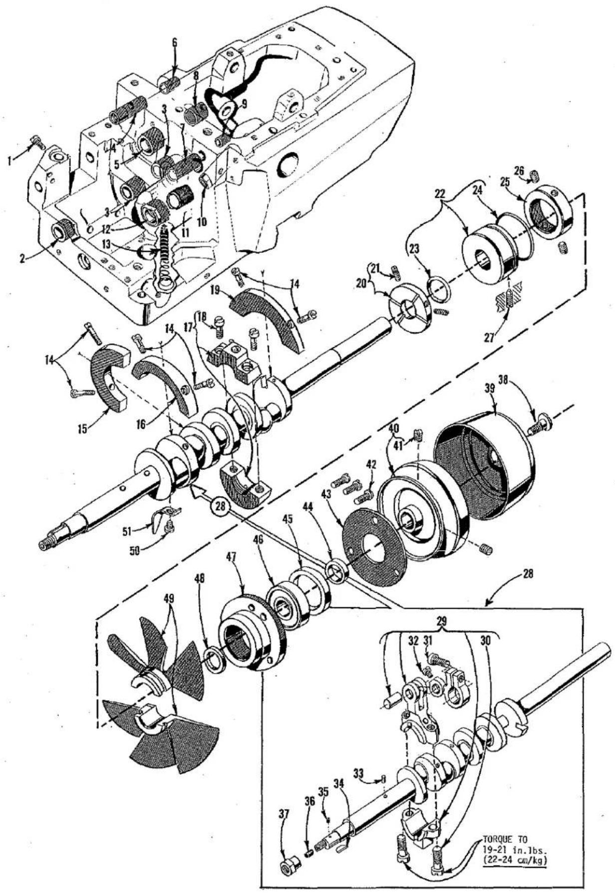
TORQUE TO 19-21 in.1bs. (22-24 cm/kg)CRANKSHAFT MECHANISM AND BUSHINGS
| Ref.No. | PartNo. | Description | Amt.Req. |
| 1 | 22569 | Screw, for cloth plate stud | 1 |
| 2 | 39536 CD | Differential Feed Rocker Shaft Bushing, left | 1 |
| 3 | 39536 BY | Differential Feed Rocker Shaft Bushing, middle and right | 2 |
| 4 | 39555 P | Foot Lifter Shaft Bushing, left | 1 |
| 5 | 39573 K | Upper Knife Driving Arm Bushing, left | 1 |
| 6 | 39555 R | Foot Lifter Shaft Bushing, right | 1 |
| 7 | 39552 U | Needle Driving Arm Crank Bushing, left | 1 |
| 8 | 39573 AA | Upper Knife Driving Arm Bushing, right | 1 |
| 9 | 39552 P | Needle Driving Arm Crank Bushing, right | 1 |
| 10 | 39544 X | Lower Looper Bar Bushing | 1 |
| 11 | 39590 T | Crankshaft Bushing, inner right | 1 |
| 12 | 39590 U | Crankshaft Bushing, left | 1 |
| 13 | 666-94 | Oil Wick and Spring, for crankshaft bushing | 1 |
| 14 | 22747 B | Screw, for counterweights | 6 |
| 15 | 39591 A | Crankshaft Counterweight, middle | 1 |
| 16 | 39591 K | Crankshaft Counterweight, left | 1 |
| 17 | 39590 V | Split Bearing and Oil Pump | 1 |
| 18 | 97 A | Screw, for split bearing and oil pump | 2 |
| 19 | 39591 B | Crankshaft Counterweight, right | 1 |
| 20 | 39590 P | Oil Slinger Collar | 1 |
| 21 | 77 Q | Set Screws, for oil slinger collar | 2 |
| 22 | 39590 X | Crankshaft Bearing, inner right | 1 |
| 23 | 660-204 | Oil Seal Ring | 1 |
| 24 | 660-443 | Oil Seal Ring | 1 |
| 25 | 39591 H | Fan Collar | 1 |
| 26 | 22894 D | Spot Screw, for fan collar | 2 |
| 27 | 22565 F | Spot Screw, for crankshaft bearing inner, right | 1 |
| 28 | 29477 LS | Crankshaft Assembly, for Styles 39500 PA and PE | 1 |
| - | 29477 LT | Crankshaft Assembly, for Styles 39500 PF, PP, PT and PW | 1 |
| 29 | 29477 MC | Needle Driving Arm Crank and Connecting Rod Assembly | 1 |
| 30 | 22587 M | Screw, for needle driving arm connecting rod | 2 |
| 31 | 22596 H | Screw, for needle driving arm crank | 1 |
| 32 | 22768 C | Screw, for needle driving arm connecting rod pin- | 1 |
| 33 | 51-228 Blk. | Vent Plug | 1 |
| 34 | 39541 A | Feed Driving Eccentric Key | 1 |
| 35 | 30-106 Blk. | Wood Plug | 1 |
| 36 | C067 E | Cork Plug | 1 |
| 37 | 39536 BL | Nut, for crankshaft | 1 |
| 38 | 22769 B | Screw, for pulley cap | 1 |
| 39 | 39521 D | Pulley Cap | 1 |
| 40 | 39521 G | Pulley | 1 |
| 41 | 95 | Set Screw, for pulley | 2 |
| 42 | 22569 B | Screw, for ball bearing housing | 3 |
| 43 | 39590 H | Ball Bearing Retaining Plate | 1 |
| 44 | 39590 S | Spacing Collar | 1 |
| 45 | 39590 R | Ball Bearing Stop Collar | 1 |
| 46 | 660-268 | Crankshaft Ball Bearing | 1 |
| 47 | 39590 G | Ball Bearing Housing | 1 |
| 48 | 39590 J | Thrust Washer | 1 |
| 49 | 39591 L | Fan, for chamber cooling | 1 |
| 50 | 87 U | Screw, for oil splasher | 1 |
| 51 | 39594 N | Oil Splasher | 1 |

text_image
TORQUE TO 38-40 in.1bs. (44-46 cm/kg) TORQUE TO 19-20 in.1bs. (22-23 cm/kg) TORQUE TO 19-20 in.1bs. (22-23 cm/kg) TORQUE TO 19-20 in.1bs. (22-23 cm/kg)FEED DRIVE MECHANISM
| Ref. No. | Part No. | Description | Amt Rec |
| 1 | 39536 AN | Feed Drive Rock Shaft | 1 |
| 1A | 22651 AB-3 | Set Screw, for feed drive rock shaft | 2 |
| 2 | 660-467 | Truarc Ring, for feed drive rock shaft | 1 |
| 3 | 39536 BE | Stud, for main feed drive segment | 1 |
| 4 | 39536 AM-247 | Main Feed Segment Sliding Block, marked "G", .247 inch | 1 |
| - | 39536 AM-248 | Main Feed Segment Sliding Block, marked "H", .248 inch | 1 |
| - | 39536 AM-249 | Main Feed Segment Sliding Block, marked "J", .249 inch | 1 |
| 5 | 39536 AY-247 | Differential Feed Segment Sliding Block, marked "K", .247 inch | 1 |
| - | 39536 AY-248 | Differential Feed Segment Sliding Block, marked "L", .248 inch | 1 |
| - | 39536 AY-249 | Differential Feed Segment Sliding Block, marked "M", .249 inch | 1 |
| 6 | 22733 | Set Screw, for differential feed segment sliding block | 1 |
| 7 | 62244 A | Thrust Washer, for feed drive rock shaft | 2 |
| 8 | 51236 A | Link Pin, for differential feed drive lever | 1 |
| 9 | 35751 G | Collar, for feed drive rock shaft | 2 |
| 10 | 22572 B | Screw, for collar | 1 |
| 11 | 39536 AL | Differential Feed Drive Lever | 1 |
| 12 | 40-139 | Washer, for differential feed drive lever | 1 |
| 13 | 22852 A | Screw, for differential feed drive lever | 1 |
| 14 | 39536 AR | Differential Feed Drive Segment | 1 |
| 15 | 80557 | Washer, for differential feed drive segment | 1 |
| 16 | 22852 A | Screw, for differential feed drive segment | 1 |
| 17 | 39536 CM | Main Feed Drive Segment | 1 |
| 18 | 39535 L | Feed Adjusting Pin | 1 |
| 19 | 22597 A | Screw, for feed adjusting pin and feed bar guide pin | 2 |
| 20 | 39536 BX | Feed Bar Thrust Washer | 1 |
| 21 | 39534 S | Main Feed Bar | 1 |
| 22 | 39535 J | Feed Bar Guide Block | 1 |
| 23 | 39535 N | Guide Pin, for differential feed bar | 1 |
| 24 | 39534 T | Differential Feed Bar | 1 |
| 25 | 39536 AX | Differential Feed Drive Link | 1 |
| 26 | 39536 BA | Differential Feed Control Link | 1 |
| 27 | 39536 BB | Differential Feed Drive Link Pin | 1 |
| 28 | 39536 AU | Differential Feed Drive Connecting Rod | 1 |
| 29 | 77 | Screw, for differential feed drive connecting rod | 1 |
| 30 | 39540 E | Differential Feed Eccentric, for Styles 39500 PA and PE | 1 |
| - | 39540 F | Differential Feed Eccentric, for Styles 39500 PF, PP, PT and PW | 1 |
| 31 | 22894 AA | Spot Screw, for differential feed eccentric | 1 |
| 32 | 22760 E | Screw, for differential feed control link | 1 |
| 33 | 39536 E | Nut, for differential feed bar stud | 1 |
| 34 | 39536 BU | Differential Feed Drive Eccentric Ferrule | 1 |
| 35 | 39536 BE | Differential Feed Bar Drive Stud | 1 |
| 36 | 39526 AP | Differential Feed Dog, 16 teeth per inch, for Styles 39500 PA and PF | 1 |
| - | 39526 AE | Differential Feed Dog, 12 teeth per inch, for Style 39500 PP | 1 |
| 36A | 39526 BP | Differential Feed Dog, 16 teeth per inch, for Style 39500 PE | 1 |
| 36B | 39526 BH | Differential Feed Dog, 16 teeth per inch, for Style 39500 PT | 1 |
| 36C | 39526 W | Differential Feed Dog, 12 teeth per inch, for Style 39500 PW | 1 |
| 37 | 22528 | Screw, for differential feed dog | 1 |
| 38 | 39535 K | Guide Block, for main feed bar | 1 |
| 39 | 98 A | Screw, for guide block | 2 |
| 40 | 39536 J | Stud, for main feed bar | 1 |
| 41 | 39536 BC | Main Feed Drive Stud Ferrule | 1 |
| 42 | 39505 L | Chaining Feed Dog, marked "V", 16 teeth per inch, for Styles 39500 PA, PF and PP- | 1 |
| 42A | 39505 BB | Chaining Feed Dog, marked "PD", 16 teeth per inch, for Style 39500 PE | 1 |
| - | 39505 AW | Chaining Feed Dog, marked "FK", 16 teeth per inch, for Style 39500 PT | 1 |
| 43 | 39505 BP | Main Feed Dog, marked "FW", 16 teeth per inch, for Styles 39500 PA and PF | 1 |
| - | 39505 AY | Main Feed Dog, marked "PH", 12 teeth per inch, for Style 39500 PP | 1 |
| 43A | 39505 BA | Main Feed Dog, marked "PC", 16 teeth per inch, for Style 39500 PE | 1 |
| 43B | 39505 BL | Main Feed Dog, marked "QX", 16 teeth per inch, for Style 39500 PT | 1 |
| 43C | 39505 WA | Main Feed Dog, marked "WA", 12 teeth per inch, for Style 39500 PW | 1 |
| 44 | 94 | Screw, for main feed dog | 1 |
| 45 | 22747 | Screw, for chaining feed dog | 1 |
| 46 | 39540 G-13 | Main Feed Eccentric, marked "EH" | 1 |
| 47 | 39536 BM | Main Feed Drive Connecting Rod | 1 |
| 48 | 39536 E | Nut, for main feed drive connecting rod stud | 1 |
| 49 | 39536 BU | Main Feed Drive Eccentric Ferrule | 1 |
| 50 | 39538 | Feed Lift Block | 1 |
| 51 | 9937 | Nut, for main feed bar stud | 1 |
| 52 | 39536 AW | Main Feed Drive Link | 1 |
text_image
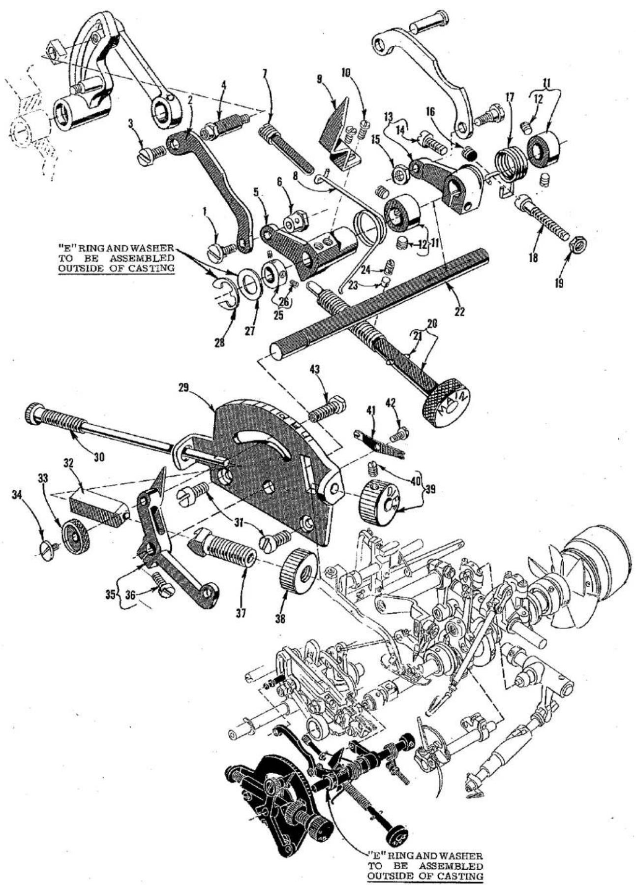
"E" RING AND WASHER TO BE ASSEMBLED OUTSIDE OF CASTING "E" RING AND WASHER TO BE ASSEMBLED OUTSIDE OF CASTINGFEED DRIVE MECHANISM
| Ref.No. | PartNo. | Description | Amt.Req. |
| 1 | 22760 E | Screw, for main feed control link ---- | 1 |
| 2 | 39536 BA | Main Feed Control Link ---- | 1 |
| 3 | 28 | Screw, for main feed linkage rod ---- | 1 |
| 4 | 39536 CG | Main Feed Linkage Rod ---- | 1 |
| 5 | 39536 AV | Main Feed Control Lever ---- | 1 |
| 6 | 39536 CK | Nut, for main feed control link screw ---- | 1 |
| 7 | 39536 CJ | Screw, for main feed return spring ---- | 1 |
| 8 | 39536 CH | Main Feed Return Spring ---- | 1 |
| 9 | 39536 BV | Main Feed Stitch Indicator ---- | 1 |
| 10 | 77 | Screw, for main feed stitch indicator ---- | 2 |
| 11 | 61248 G | Collar, for feed control shaft ---- | 2 |
| 12 | 89 | Screw, for collar ---- | 2 |
| 13 | 39536 AT | Differential Feed Control Lever ---- | 1 |
| 14 | 22652 A-6 | Screw, for differential feed control lever ---- | 1 |
| 15 | 41071 G | Nut, for differential feed control link screw ---- | 1 |
| 16 | 1025 L | Plug Screw, for bed ---- | 1 |
| 17 | 39536 CF | Differential Link Return Spring ---- | 1 |
| 18 | 294 | Screw, for differential link return spring ---- | 1 |
| 19 | 7947 | Nut, differential link return spring screw ---- | 1 |
| 20 | 39536 BM | Main Feed Stitch Regulating Screw ---- | 1 |
| 21 | 51-392 Blk. | Pin ---- | 1 |
| 22 | 39536 AP | Feed Control Shaft ---- | 1 |
| 23 | 39536 CA | Pressure Plug, for main feed stitch regulating screw -- | 1 |
| 24 | 22580 A | Pressure Plug Screw, with nylok insert ---- | 1 |
| 25 | 39536 CL | Collar, for feed control shaft ---- | 1 |
| 26 | 1096 | Screw, for collar ---- | 2 |
| 27 | 40-144 | Washer, for feed control shaft ---- | 1 |
| 28 | 660-466 | Truarc Ring, for feed control shaft ---- | 1 |
| 29 | 39536 BP | Stitch Indicator Plate ---- | 1 |
| 30 | 39536 BF | Differential Feed Stitch Regulating Screw ---- | 1 |
| 31 | 22517 | Screw, for stitch indicator plate ---- | 2 |
| 32 | 39536 BH | Differential Feed Control Regulating Nut ---- | 1 |
| 33 | 39536 BS | Differential Lever Thumb Nut ---- | 1 |
| 34 | 22784 F | Screw, for differential lever lock screw ---- | 1 |
| 35 | 39536 CB | Differential Stitch Control Lever ---- | 1 |
| 36 | 93 | Screw, for differential stitch control lever ---- | 1 |
| 37 | 39536 BG | Differential Feed Control Regulating Screw ---- | 1 |
| 38 | 39536 BJ | Differential Feed Control Regulating Stop Nut ---- | 1 |
| 39 | 39536 BK | Differential Feed Stich Regulating Knob ---- | 1 |
| 40 | 531 | Screw, differential feed stitch regulating knob---- | 1 |
| 41 | 39536 CC | Ratchet Spring ---- | 1 |
| 42 | 28 | Screw, for ratchet spring ---- | 1 |
| 43 | 39536 BR | Differential Lever Lock Screw ---- | 1 |

text_image
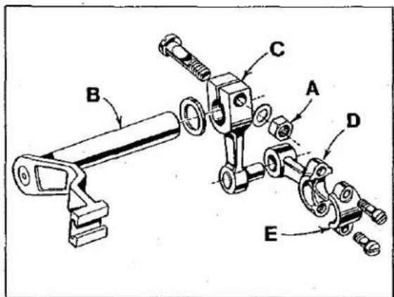
TORQUE TO 14 in.1bs. (16 cm/kg) TORQUE TO 25-26 in.1bs. (29-30 cm/kg) TORQUE TO 19-20 in.1bs. (22-23 cm/kg) TORQUE TO 19-21 in.1bs. (22-24 cm/kg) TORQUE TO 19-21 in.1bs. (22-24 cm/kg)UPPER AND LOWER LOOPER DRIVING PARTS
| Ref. No. | Part No. | Description | Amt. Req. |
| 1 | 660-206 | Oil Seal Ring, for lower looper driving shaft | 1 |
| 2 | 22894 AE | Screw, for lower looper driving shaft | 2 |
| 3 | 39544 V | Lower Looper Driving Shaft | 1 |
| 4 | 87 U | Screw, for oil splasher | 1 |
| 5 | 39594 N | Oil Splasher | 1 |
| 6 | 666-255 | Felt Plug | 1 |
| 7 | 97 | Screw, for ball joint guide fork | 2 |
| 8 | 39544 J | Ball Joint Guide Fork, for upper looper drive assembly | 1 |
| 9 | 39543 X | Upper Looper Drive Lever Shaft | 1 |
| 10 | 482 C | Upper Looper Drive Lever Shaft Collar | 1 |
| 11 | 22894 C | Screw, for collar | 2 |
| 12 | 22565 | Set Screw, for upper looper drive lever shaft | 1 |
| 12A | 22565 S | Spot Screw, for upper looper drive lever shaft | 1 |
| 13 | 39543 W | Upper Looper Drive Lever | 1 |
| 14 | 39543 M | Clamp Collar, for upper looper drive lever shaft | 1 |
| 15 | 22562 A | Screw, for clamp collar | 1 |
| 16 | 39543 P | Upper Looper Shaft Thrust Washer | 2 |
| 17 | 39543 U | Upper Looper Connecting Rod | 1 |
| 18 | 22729 D | Screw, for connecting rod | 4 |
| 19 | 29126 DF | Lower Looper Bar Driving Lever and Connecting Rod Assembly | 1 |
| 20 | 39544 N | Lower Looper Connecting Rod | 1 |
| 21 | 22729 E | Screw, for connecting rod | 2 |
| 22 | 22729 D | Screw, for connecting rod | 2 |
| 23 | 39544 S | Ball Joint Guide Fork | 1 |
| 24 | 97 | Screw, for ball joint guide fork | 2 |
| 25 | 39544 U | Lower Looper Bar Driving Lever | 1 |
| 26 | 666-255 | Felt Plug, for connecting rod | 1 |
| 27 | 39594 N | Oil Splasher | 1 |
| 28 | 87 U | Screw, for oil splasher | 1 |
| 29 | 39544 B | Lower Looper Bar Connecting Link | 1 |
| 30 | 39544 D | Lower Looper Bar Connecting Link Pin | 2 |
| 31 | 77 | Screw, for lower looper bar connecting link pin | 1 |
| 32 | 39544 | Lower Looper Bar | 1 |
| 33 | 39151 | Nut, for lower looper bar | 1 |
| 34 | 39508 B | Lower Looper | 1 |
| 35 | 39508 A | Upper Looper, marked "CC" | 1 |
| + - | 39508 C | Upper Looper, marked "CJ" | 1 |
| 36 | 39543 | Upper Looper Holder | 1 |
| 37 | 22564 G | Screw, for upper looper | 1 |
| 38 | 39543 A | Upper Looper Holder Collar | 1 |
| 39 | 77 | Screw, for upper looper holder collar | 1 |
| *40 | 39543 S | Bushing and Cam Guide | 1 |
| 41 | 22565 H | Spot Screw, for bushing and cam guide | 1 |
| 42 | 1025 L | Lock Screw, for bushing and cam guide screw | 1 |
| *43 | 39543 T | Cam Follower | 1 |
| 44 | 482 C | Lower Looper Driving Shaft Collar | 1 |
| 45 | 22894 C | Screw, for collar | 2 |
| *46 | 39543 K | Upper Looper Drive Lever Shaft | 1 |
| 47 | 39543 E | Cam Follower Locking Clamp | 1 |
| 48 | 22503 F | Screw, for cam follower locking clamp | 1 |
| 49 | 77 | Screw, for lower looper bar connecting link pin | 1 |
- Shipped with Style 39500 PW machine for converting stitch type 512 SSa-2 to stitch type 514 SSa-2.
* The use of assembly No. 29126 EC is recommended instead of the individual parts.
text_image
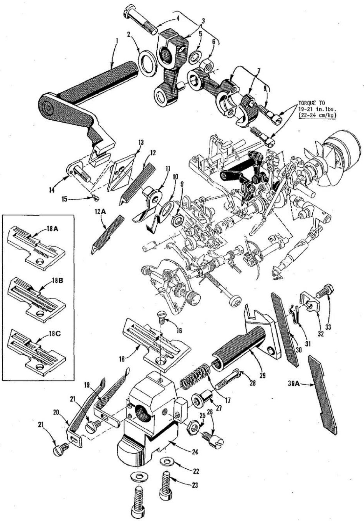
TORQUE 70 19-21 in.1bs. (22-24 cm/kg) 18A 18B 18C 12A 13 14 15 16 17 18 19 20 21 22 23 24 25 26 27 28 29 30A 31 32 33 30 10 9 11 12 13 14 15 16 17 18ANEEDLE GUARDS, THROAT PLATE, UPPER AND LOWER KNIFE MECHANISM
| Ref. No. | Part No. | Description | Amt. Req. |
| 1 | 39573 H | Upper Knife Driving Arm | 1 |
| 2 | 39573 A | Upper Knife Driving Arm Washer | 1 |
| 3 | 39573 E | Upper Knife Driving Lever | 1 |
| 4 | 55235 D | Locking Stud, for upper knife driving lever | 1 |
| 5 | 6042 A | Washer, for upper knife driving lever | 1 |
| 6 | 55235 E | Nut, for upper knife driving lever | 1 |
| 7 | 39573 J | Upper Knife Driving Connecting Rod | 1 |
| 8 | 22587 J | Screw, for upper knife driving connecting rod | 2 |
| 9 | 14077 | Nut, for upper knife clamp stud | 1 |
| 10 | 39571 B | Upper Knife Chain Guard | 1 |
| 11 | 39571 F | Upper Knife Clamp | 1 |
| 12 | 39570 | Upper Knife, for Styles 39500 PA, PE, PF and PP | 1 |
| 12A | 39570 J | Upper Knife, for Styles 39500 PT and PW | 1 |
| 13 | 39572 | Upper Knife Holder Block | 1 |
| 14 | 39571 D | Upper Knife Clamp Stud | 1 |
| 15 | 22738 | Screw, for upper knife clamp stud | 1 |
| 16 | 22524 | Screw, for throat plate | 1 |
| 17 | 39550 E | Lower Knife Holder Spring | 1 |
| 18 | 39524 C-3/32 | Throat Plate, marked "AC-3/32", for 3/32 inch (2.4mm) wide seam, for Styles 39500 PA, PF and PP | 1 |
| - | 39524 C-1/8 | Throat Plate, marked "AC-1/8", for 1/8 inch (3.2mm) wide seam, for Styles 39500 PA, PF and PP | 1 |
| - | 39524 C-5/32 | Throat Plate, marked "CU", for 5/32 inch (4mm) wide seam, for Styles 39500 PA, PF and PP | 1 |
| 18A | 39524 BP-3/32 | Throat Plate, marked "CS", for 3/32 inch (2.4mm) wide seam, for Style 39500 PE | 1 |
| - | 39524 BP-1/8 | Throat Plate, marked "CT", for 1/8 inch (3.2mm) wide seam, for Style 39500 PE | 1 |
| - | 39524 BP-5/32 | Throat Plate, marked "CV", for 5/32 inch (4mm) wide seam, for Style 39500 PE | 1 |
| 18B | 39524 S | Throat Plate, marked "AK", for 1/8 inch (3.2mm) wide seam, for Style 39500 PT | 1 |
| 18C | 39524 W | Throat Plate, marked "AN", for Style 39500 PW | 1 |
| 19 | 39525 A | Needle Guard, rear, for Styles 39500 PA, PE, PF, PP and PT | 1 |
| - | 39525 N | Needle Guard, rear, for Style 39500 PW | 1 |
| 20 | 39525 | Needle Guard, front, for Styles 39500 PA, PE, PF, PP and PT | 1 |
| - | 39525 M | Needle Guard, front, for Style 39500 PW | 1 |
| 21 | 22585 A | Screw, for needle guard | 2 |
| 22 | 39580 F | Washer, for throat plate and lower knife support bracket | 2 |
| 23 | 22653 B-12 | Screw, for throat plate and lower knife support bracket | 2 |
| 24 | 39580 AH | Throat Plate and Lower Knife Support Bracket | 1 |
| 25 | 14077 | Nut, for lower knife holder locking screw | 1 |
| 26 | 22892 B | Locking Screw, for lower knife holder | 1 |
| 27 | 39550 C | Lower Knife Holder Locking Stud | 1 |
| 28 | 22729 B | Screw, for lower knife holder locking stud | 1 |
| 29 | 39550 S | Lower Knife Holder | 1 |
| 30 | 39549 | Lower Knife, for Styles 39500 PA, PE, PF and PP | 1 |
| 30A | 39549 J | Lower Knife, for Styles 39500 PT and PW | 1 |
| 31 | 39550 M | Lower Knife Clamp Spring | 1 |
| 32 | 39550 Z | Lower Knife Clamp | 1 |
| 33 | 22588 J | Screw, for lower knife clamp | 1 |

text_image
Technical diagram of mechanical assembly with numbered parts and exploded views, likely from an engineering manual.PRESSER FOOT, PRESSER FOOT LIFTER AND NEEDLE DRIVE PARTS
| Ref.No. | PartNo. | Description | Amt.Req. |
| 1 | 39520 B | Presser Foot Assembly, for Styles 39500 PA, PF and PP ---- | 1 |
| 2 | 39597 A | Stitch Tongue, marked "DS" ---- | 1 |
| 3 | 39530 P | Chip Guard ---- | 1 |
| 4 | 22738 B | Screw, for chip guard ---- | 1 |
| 5 | 39530 | Hinge Spring ---- | 1 |
| 6 | 22768 B | Screw, for stitch tongue and hinge spring ---- | 1 |
| 7 | 22738 B | Screw, for chain shield ---- | 1 |
| 8 | 39530 C | Chain Shield ---- | 1 |
| 9 | 605 A | Screw, for presser foot hold down plate ---- | 2 |
| 10 | 39556 H | Presser Foot Hold Down Plate ---- | 1 |
| 11 | 39556 F | Presser Arm, for Styles 39500 PA, PF, PP, PT and PW -- | 1 |
| 11A | 39556 K | Chain Cutting Knife, for Style 39500 PW ---- | 1 |
| 11B | 22704 | Screw, for Style 39500 PW ---- | 1 |
| 11C | 39556 J | Presser Arm, for Style 39500 PE ---- | 1 |
| 12 | 22791 H | Screw, for presser arm ---- | 1 |
| 13 | 258 A | Nut, for presser arm screw ---- | 1 |
| 14 | 12865 | Foot Lifter Lever Shaft Thrust Collar ---- | 1 |
| 15 | 88 | Screw, for collar ---- | 2 |
| 16 | 39555 S | Foot Lifter Lever Shaft ---- | 1 |
| 17 | 39555 C | Foot Lifter Lever Arm ---- | 1 |
| 18 | 627 | Screw, for foot lifter lever arm ---- | 1 |
| 19 | 12538 | Lock Nut, for foot lifter lever arm ---- | 2 |
| 20 | 22597 E | Screw, for foot lifter lever arm ---- | 2 |
| 21 | 39555 B | Foot Lifter Lever Spring ---- | 1 |
| 22 | 39855 | Foot Lifter Lever ---- | 1 |
| 23 | 39555 D | Foot Lifter Intermediate Lever ---- | 1 |
| 24 | 660-142 | Cotter Pin, for foot lifter lever connecting link ---- | 2 |
| 25 | 39555 F | Foot Lifter Lever Connecting Link ---- | 1 |
| 26 | 22566 B | Screw, for foot lifter lever ---- | 1 |
| 27 | 22571 D | Plug Screw, for foot lifter hole ---- | 1 |
| 28 | 14077 A | Nut, for needle clamp stud ---- | 1 |
| 29 | 39551 H | Needle Clamp Washer, for Styles 39500 PA, PE, PF, PP and PT ---- | 1 |
| 30 | 39552 Z | Needle Driving Arm, marked "K", for Styles 39500 PA, PE, PF, PP and PT ---- | 1 |
| 31 | 50-774 Blk. | Stop Pin ---- | 1 |
| 32 | 22596 E | Screw ---- | 1 |
| 33 | 22513 | Screw, for looper thread pull-off ---- | 1 |
| 34 | 39568 A | Looper Thread Pull-off ---- | 1 |
| 35 | 39568 AC | Looper Thread Pull-off Lever ---- | 1 |
| 36 | 88 B | Screw ---- | 2 |
| 37 | 39552 AG | Oil Seal, for needle driving shaft ---- | 1 |
| 38 | 660-207 | "0" Ring ---- | 1 |
| 39 | 39543 Y | Needle Drive Shaft Thrust Collar ---- | 1 |
| 40 | 22782 A | Screw, for needle drive shaft thrust collar ---- | 1 |
| 41 | 39594 N | Oil Splasher ---- | 1 |
| 42 | 87 U | Screw, for oil splasher ---- | 1 |
| 43 | 39552 R | Needle Driving Shaft ---- | 1 |
| 44 | 87 U | Screw, for needle thread cam pull-off ---- | 1 |
| 45 | 39563 G | Needle Thread Cam Pull-off ---- | 1 |
| 46 | 39551 J | Needle Clamp Stud ---- | 1 |
| 47 to 79 | See following page | ||
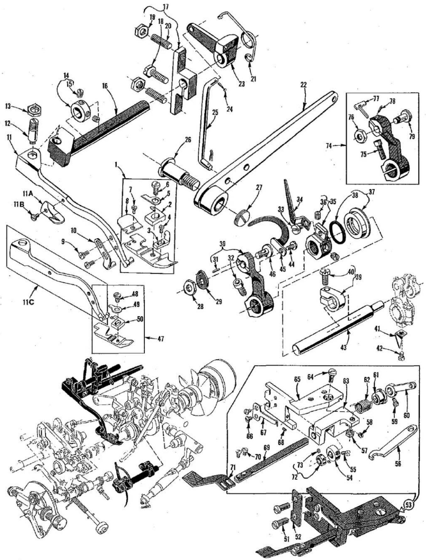
text_image
Technical diagram of mechanical assembly with numbered parts and exploded views, likely from an engineering manual.| Ref. No. | Part No. | Description | Amt. Req. |
| 1 to 46 | See preceding page | ||
| 47 | 39520 BP | Presser Foot Assembly, for Style 39500 PE | 1 |
| - | 39520 BL | Presser Foot Assembly, for Style 39500 PT | 1 |
| - | 39520 W | Presser Foot Assembly, for Style 39500 PW | 1 |
| 48 | 22768 B | Screw, for Styles 39500 PE and PW | 1 |
| - | J87 J | Screw, for Style 39500 PT | 1 |
| 49 | 39530 G | Hinge Spring, for Styles 39500 PE and PT | 1 |
| - | 39530 | Hinge Spring, for Style 39500 PW | 1 |
| 50 | 39597 BP | Stitch Tongue, marked "FA", for Style 39500 PE | 1 |
| - | 39597 AY | Stitch Tongue, marked "FB", for Style 39500 PT | 1 |
| - | 39597 W | Stitch Tongue, marked "EF", for Style 39500 PW | 1 |
| 51 | 22569 C | Screw | 2 |
| 52 | 39531 Z | Washer Plate | 1 |
| 53 | 29480 RB | Pressure Plate Assembly, for Style 39500 PT | 1 |
| 54 | 39831 C | Acuating Collar | 1 |
| 55 | 22768 | Screw | 1 |
| 56 | 21388 Y | Spanner Wrench | 1 |
| 57 | 12934 A | Nut | 1 |
| 58 | 22743 | Screw | 1 |
| 59 | 87 A | Screw | 1 |
| 60 | 39831 G | Operating Lever | 1 |
| 61 | 39831 D | Shaft Collar | 1 |
| 62 | 39831 E | Tension Spring | 1 |
| 63 | 39831 B | Shaft Bracket | 1 |
| 64 | 22758 J | Screw | 1 |
| 65 | 39831 A | Mounting Bracket | 1 |
| 66 | 22561 | Screw | 2 |
| 67 | 39831 F | Spring | 1 |
| 68 | 73 C | Screw | 1 |
| 69 | 39831 | Pressure Plate Shaft | 1 |
| 70 | 22768 | Screw | 2 |
| 71 | 39531 AB | Pressure Plate | 1 |
| 72 | 39536 CL | Collar | 1 |
| 73 | 1096 | Screw | 2 |
| 74 | 39552 AC | Needle Driving Arm, marked "N", for Style 39500 PW | 1 |
| 75 | 22596 E | Screw | 1 |
| 76 | 14077 A | Nut, for needle clamp stud | 1 |
| 77 | 39551 G | Needle Spacer | 1 |
| 78 | 61351-K625 | Stop Pin | 1 |
| 79 | 39551 J | Needle Clamp Stud | 1 |

text_image
Exploded view diagram of a mechanical assembly with numbered parts and labeled features like 'Union Speed' and 40A.THREAD TENSION PARTS, PRESSER SPRING, TOP COVER AND MISCELLANEOUS EYELETS
| Ref.No. | PartNo. | Description | Amt.Req. |
| 1 | 39592 Z | Left Needle Tension Nut, yellow, for Style 39500 PW | 1 |
| - | 39592 AA | Right Needle Tension Nut, green | 1 |
| - | 39592 AB | Upper Looper Tension Nut, blue | 1 |
| - | 39592 AC | Lower Looper Tension Nut, red | 1 |
| 2 | 39592 AK | Tension Spring Ferrule | 3 or 4 |
| 3 | 39592 AR-5 | Looper Thread Tension Spring | 2 |
| - | 39592 AR-5 | Needle Thread Tension Spring, for Styles 39500 PA and PE | 1 |
| 4 | 39592 AR-8 | Needle Thread Tension Spring, for Styles 39500 PF, PP, PTand PW | 1 or 2 |
| 5 | 39592 AD | Thread Tension Disc | 6 or 8 |
| 6 | 39592 AF | Tension Disc Felt | 3 or 4 |
| 7 | 39592 AL | Tension Post | 3 or 4 |
| 8 | 8372 A | Washer, for tension post | 3 or 4 |
| 9 | 39592 AM | Tension Post Bar, for Styles 39500 PA, PE, PF, PP and PT | 1 |
| 9A | 39592 AN | Tension Post Bar, for Style 39500 PW | 1 |
| 10 | 39592 AG-3 | Tension Post Mounting Bracket, for Styles 39500 PA, PE, PF,PP and PT | 1 |
| 10A | 39592 AG-5 | Tension Post Mounting Bracket, for Style 39500 PW | 1 |
| 11 | 39592 AH | Tension Post Nut | 3 or 4 |
| 12 | 22847 B | Screw, for tension post mounting bracket | 1 |
| 13 | 22806 A | Screw, for tension post mounting bracket | 1 |
| 14 | 39557 A | Presser Spring Plunger | 1 |
| 15 | 39563 F | Top Cover Needle Thread Eyelet, for Styles 39500 PA, PE, PF,PP and PT | 1 |
| 15A | 39563 W | Top Cover Needle Thread Eyelet, for Style 39500 PW | 1 |
| 16 | 22569 B | Screw, for top cover needle thread eyelet | 2 |
| 17 | 39556 A | Presser Foot Release Bushing | 1 |
| 18 | 39557 | Presser Spring | 1 |
| 19 | 39557 F | Locknut, for plunger adjusting screw | 1 |
| 20 | 39557 C | Presser Spring Plunger Adjusting Screw | 1 |
| 21 | 39557 E | Presser Spring Plunger Locknut | 1 |
| 22 | 39557 B | Presser Spring Plunger Capnut | 1 |
| 23 | 39582 AD | Top Cover, for Styles 39500 PA, PE, PF, PP and PT | 1 |
| - | 39582 AK | Top Cover, for Style 39500 PW | 1 |
| 24 | 22562 A | Screw, for hinge bracket | 1 |
| 25 | 39582 AF | Oil Filler Cover | 1 |
| 26 | 39582 V | Spring | 1 |
| 27 | 39582 AG | Hinge Bracket | 1 |
| 28 | 51-103 Blk. | Hinge Pin | 1 |
| 29 | 39582 W | Oil Guard | 1 |
| 30 | 22541 | Screw, for top cover | 8 |
| 31 | 39582 AE | Gasket, for top cover | 1 |
| 32 | 22569 B | Screw, for looper thread eyelet mounting bracket | 1 |
| 33 | 43139 A | Nut, for looper thread eyelet screw | 2 |
| 34 | 39568 D | Looper Thread Eyelet Mounting Bracket | 1 |
| 35 | 39582 BN | Oil Shield, upper | 1 |
| 36 | 22569 C | Screw, for upper oil shield | 2 |
| 37 | 22513 | Screw, for lower looper thread eyelet | 1 |
| 38 | 39568 AA | Lower Looper Thread Eyelet | 1 |
| 39 | 87 B | Screw, for fabric guard | 2 |
| 40 | 39578 M | Fabric Guard, for Styles 39500 PA, PF, PP and PT | 1 |
| 40A | 39578 AF | Fabric Guard, for Style 39500 PE | 1 |
| - | 39578 S | Fabric Guard, for Style 39500 PW | 1 |
| 41 | 22513 | Screw, for oil shield | 2 |
| 42 | 39582 BP | Oil Shield, end | 1 |
| 43 | 39568 L | Upper Looper Thread Eyelet | 1 |
| 44 | 39568 B | Lower Looper Thread Eyelet | 1 |
| 45 | 376 A | Screw, for thread eyelet | 2 |
| 46 | 39568 E | Auxiliary Looper Thread Eyelet | 1 |
text_image
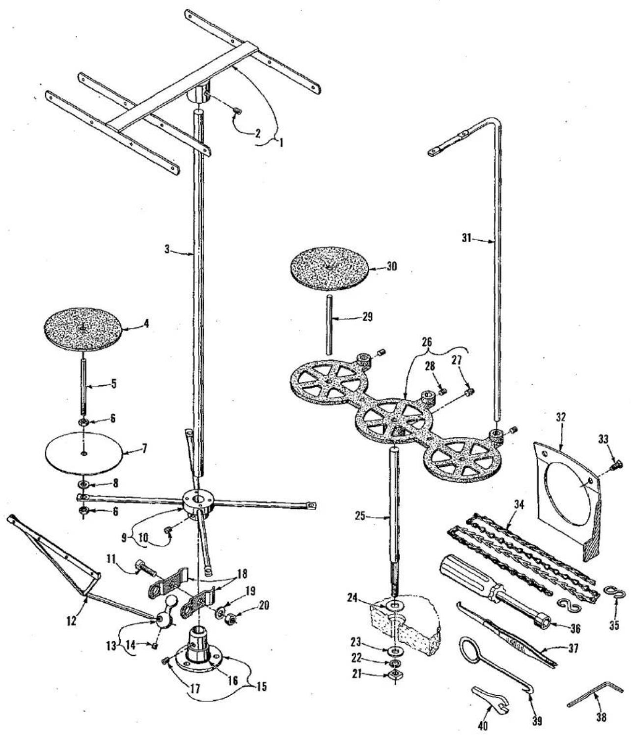
Technical diagram of a mechanical device with numbered components for identification and assembly reference.THREAD STANDS, ACCESSORIES AND MISCELLANEOUS TOOLS
| Ref.No. | PartNo. | Description | Amt.Req. |
| 1 | 21114 AQ-4 | Eyelet Support, for Style 39500 PW | 1 |
| 2 | 22651 CD-4 | Screw | 1 |
| 3 | 21104 B-20 | Thread Stand Rod, for Style 39500 PW | 1 |
| 4 | 21104 V | Pad, for thread cone, for Style 39500 PW | 4 |
| 5 | 21114 W | Spool Pin, for Style 39500 PW | 4 |
| 6 | 258 A | Nut, for Style 39500 PW | 8 |
| 7 | 21114 | Spool Seat Disc, for Style 39500 PW | 4 |
| 8 | 652-16 | Washer, for Style 39500 PW | 4 |
| 9 | 21114 D-4 | Spool Support, for Style 39500 PW | 1 |
| 10 | 22651 CD-5 | Screw | 2 |
| 11 | 22810 | Screw, for ball split socket, for Style 39500 PW | 1 |
| 12 | 21114 S-4 | Lead Eyelet, for Style 39500 PW | 1 |
| 13 | 21114 T | Lead Eyelet Socket Ball, for Style 39500 PW | 1 |
| 14 | 22651 CD-4 | Screw | 1 |
| 15 | 21114 A | Thread Stand Base, for Style 39500 PW | 1 |
| 16 | 660-738 | Cap | 1 |
| 17 | 22651 CD-4 | Screw | 1 |
| 18 | 21114 U | Ball Split Socket, for Style 39500 PW | 2 |
| 19 | 652-16 | Washer, for Style 39500 PW | 1 |
| 20 | 21104 H | Nut, for Style 39500 PW | 1 |
| 21 | 651 A-16 | Nut, for Style 39500 PA, PE, PF, PP and PT | 1 |
| 22 | WA9 A | Lockwasher, for Styles 39500 PA, PE, PF, PP and PT | 1 |
| 23 | 652 J-16 | Washer, for Styles 39500 PA, PE, PF, PP and PT | 1 |
| 24 | 652 J-24 | Washer, for Styles 39500 PA, PE, PF, PP and PT | 1 |
| 25 | 21104 AA | Thread Stand Rod, for Styles 39500 PA, PE, PF, PP and PT | 1 |
| 26 | 21130 W-3 | Cone Support, for Styles 39500 PA, PE, PF, PP and PT | 1 |
| 27 | 22650 CE-6 | Screw | 1 |
| 28 | 22650 CB-4 | Screw | 3 |
| 29 | 69 S | Spool Pin, for Styles 39500 PA, PE, PF, PP and PT | 3 |
| 30 | 21104 V | Pad, for Styles 39500 PA, PE, PF, PP and PT | 3 |
| 31 | 21113 F | Thread Stand Eyelet, for Styles 39500 PA, PE, PF, PP and PT | 3 |
| 32 | 21375 BB | Belt Guard | 1 |
| 33 | 80 | Screw | 2 |
| 34 | 421 D-34 | Presser Foot Lifter Chain, 32 3/64 inch (812.8mm) long | 1 |
| 35 | 660-264 | "S" Hook | 2 |
| 36 | 21388 AU | Socket Wrench, for 3/8 inch (9.5mm) nuts | 1 |
| 37 | 660-240 | Thread Tweezers | 1 |
| 38 | WR-56 | Allen Wrench, 1/8 inch (3.2mm), for Style 39500 PW | 1 |
| 39 | 21227 BF. | Feed Eccentric Hook | 1 |
| 40 | 116 | Wrench, for 9/32 inch (7.1mm) nut | 1 |
| 652-24 | Washer, not shown, for Styles 39500 PA, PE, PF, PP and PT | 8 | |
| 660-458 | Dust Cover, not shown | 1 | |
| 28604 R | Container for Oil, 16 ounces (455 ml.), Spec. 175, not shown | 1 |
NUMERICAL INDEX OF PARTS
| Part No. | Page No. | Part No. | Page No. | Part No. | Page No. |
| WA9 A | 45 | 14077 A | 39,41 | 22768 C | 29 |
| 28 | 33 | 21104 B-20 | 45 | 22782 A | 39 |
| 30-106 Blk | 29 | 21104 H | 45 | 22784 F | 33 |
| 40-139 | 31 | 21104 V | 45 | 22791 H | 39 |
| 40-144 | 33 | 21104 AA | 45 | 22806 A | 27,43 |
| 50-774 Blk | 39 | 21113 F | 45 | 22810 | 45 |
| 51-103 Blk | 43 | 21114 | 45 | 22824 | 27 |
| 51-228 Blk | 29 | 21114 A | 45 | 22847 B | 43 |
| 51-392 Blk | 33 | 21114 D-4 | 45 | 22852 A | 31 |
| WR56 | 45 | 21114 S-4 | 45 | 22892 B | 37 |
| C067 E | 29 | 21114 T | 45 | 22894 C | 35 |
| 69 S | 45 | 21114 U | 45 | 22894 D | 29 |
| 73 C | 41 | 21114 W | 45 | 22894 AA | 31 |
| 74 E | 27 | 21114 AQ-4 | 45 | 22894 AE | 35 |
| 77 | 31,33,35 | 21130 W-3 | 45 | 28604 R | 45 |
| 77 Q | 29 | 21227 BF | 45 | 29126 DF | 35 |
| 80 | 45 | 21375 BB | 45 | 29126 EC | 35 |
| 87 A | 41 | 21388 Y | 41 | 29477 GM | 27 |
| 87 B | 43 | 21388 AU | 45 | 29477 LS | 29 |
| J87 J | 41 | 22503 F | 35 | 29477 LT | 29 |
| 87 U | 29,35,39 | 22513 | 39,43 | 29477 MC | 29 |
| 88 | 39 | 22517 | 33 | 29480 RB | 41 |
| 88 B | 39 | 22524 | 37 | 35751 G | 31 |
| 89 | 33 | 22528 | 31 | 39151 | 35 |
| 90 | 27 | 22541 | 43 | 39501 K | 27 |
| 93 | 33 | 22561 | 41 | 39501 DL | 27 |
| 94 | 31 | 22562 A | 35,43 | 39501 DLB | 27 |
| 95 | 29 | 22564 G | 35 | 39505 L | 31 |
| 97 | 35 | 22565 | 27,35 | 39505 AM | 31 |
| 97 A | 29 | 22565 F | 29 | 39505 AY | 31 |
| 98 A | 31 | 22565 H | 35 | 39505 BA | 31 |
| 116 | 45 | 22565 S | 27,35 | 39505 BB | 31 |
| 138 | 27 | 22566 B | 39 | 39505 BL | 31 |
| 258 A | 39,45 | 22569 | 27,29 | 39505 BP | 31 |
| 294 | 33 | 22569 B | 27,29,43 | 39505 WA | 31 |
| 376 A | 43 | 22569 C | 27,41,43 | 39508 A | 35 |
| 421 D-34 | 45 | 22569 D | 27 | 39508 B | 35 |
| 482 C | 35 | 22569 J | 27 | 39508 C | 35 |
| 531 | 33 | 22569 K | 27 | 39520 B | 39 |
| 605 A | 39 | 22571 D | 39 | 39520 W | 41 |
| 627 | 39 | 22571 E | 27 | 39520 BL | 41 |
| 651 A-16 | 45 | 22572 A | 27 | 39520 BP | 41 |
| 652-16 | 45 | 22572 B | 31 | 39521 D | 29 |
| 652-24 | 45 | 22580 A | 33 | 39521 G | 29 |
| 652 J-16 | 45 | 22585 A | 37 | 39524 C-3/32 | 37 |
| 652 J-24 | 45 | 22586 R | 27 | 39524 C-1/8 | 37 |
| 660-142 | 39 | 22587 J | 37 | 39524 C-5/32 | 37 |
| 660-204 | 29 | 22587 M | 29 | 39524 S | 37 |
| 660-206 | 35 | 22588 J | 37 | 39524 W | 37 |
| 660-207 | 39 | 22596 E | 39,41 | 39524 BP-3/32 | 37 |
| 660-240 | 45 | 22596 H | 29 | 39524 BP-1/8 | 37 |
| 660-243 | 27 | 22597 A | 31 | 39524 BP-5/32 | 37 |
| 660-264 | 45 | 22597 E | 39 | 39525 | 37 |
| 660-268 | 29 | 22650 CB-4 | 45 | 39525 A | 37 |
| 660-443 | 29 | 22650 CE-6 | 45 | 39525 M | 37 |
| 660-458 | 45 | 22651 AB-3 | 31 | 39525 N | 37 |
| 660-466 | 33 | 22651 CD-4 | 45 | 39526 M | 31 |
| 660-467 | 31 | 22651 CD-5 | 45 | 39526 AE | 31 |
| 660-506 | 27 | 22652 A-6 | 33 | 39526 AP | 31 |
| 660-738 | 45 | 22653 B-12 | 37 | 39526 BH | 31 |
| 666-94 | 29 | 22653 D-4 | 27 | 39526 BP | 31 |
| 666-255 | 35 | 22657 D-12 | 27 | 39530 | 39,41 |
| 666-268 | 27 | 22704 | 39 | 39530 C | 39 |
| 666-271 | 27 | 22729 B | 37 | 39530 G | 41 |
| 666-280 | 27 | 22729 D | 35 | 39530 P | 39 |
| 667 D-8 | 27 | 22729 E | 35 | 39531 Z | 41 |
| 1025 L | 33,35 | 22733 | 31 | 39531 AB | 41 |
| 1096 | 33,41 | 22738 | 37 | 39532 A | 27 |
| 6042 A | 37 | 22738 B | 39 | 39534 S | 31 |
| 7947 | 33 | 22743 | 27,41 | 39534 T | 31 |
| 8372 A | 43 | 22747 | 31 | 39535 J | 31 |
| 9937 | 31 | 22747 B | 29 | 39535 K | 31 |
| 12538 | 39 | 22758 J | 41 | 39535 L | 31 |
| 12865 | 39 | 22760 E | 31,33 | 39535 M | 27 |
| 12934 A | 41 | 22768 | 41 | 39535 N | 31 |
| 14077 | 37 | 22768 B | 39,41 | 39535 P | 27 |
NUMERICAL INDEX OF PARTS
| Part No. | Page No. | Part No. | Page No. | Part No. | Page No. |
| 39536 E. | 31 | 39550 E. | 37 | 39582 BF. | 27 |
| 39536 J. | 31 | 39550 M. | 37 | 39582 BN. | 43 |
| 39536 AL. | 31 | 39550 S. | 37 | 39582 BP. | 43 |
| 39536 AM-247. | 31 | 39550 Z. | 37 | 39582 BU. | 27 |
| 39536 AM-248. | 31 | 39551 G. | 41 | 39582 XE. | 27 |
| 39536 AM-249. | 31 | 39551 H. | 39 | 39590 G. | 29 |
| 39536 AN. | 31 | 39551 J. | 39,41 | 39590 H. | 29 |
| 39536 AP. | 33 | 39552 P. | 29 | 39590 J. | 29 |
| 39536 AR. | 31 | 39552 R. | 39 | 39590 P. | 29 |
| 39536 AT. | 33 | 39552 U. | 29 | 39590 R. | 29 |
| 39536 AU. | 31 | 39552 Z. | 39 | 39590 S. | 29 |
| 39536 AV. | 33 | 39552 AC. | 41 | 39590 T. | 29 |
| 39536 AW. | 31 | 39552 AG. | 39 | 39590 U. | 29 |
| 39536 AX. | 31 | 39555 B. | 39 | 39590 V. | 29 |
| 39536 AY-247. | 31 | 39555 C. | 39 | 39590 X. | 29 |
| 39536 AY-248. | 31 | 39555 D. | 39 | 39591 A. | 29 |
| 39536 AY-249. | 31 | 39555 F. | 39 | 39591 B. | 29 |
| 39536 BA. | 31,33 | 39555 P. | 29 | 39591 H. | 29 |
| 39536 BB. | 31 | 39555 R. | 29 | 39591 K. | 29 |
| 39536 BC. | 31 | 39555 S. | 39 | 39591 L. | 29 |
| 39536 BE. | 31 | 39556 A. | 43 | 39592 Z. | 43 |
| 39536 BF. | 33 | 39556 F. | 39 | 39592 AA. | 43 |
| 39536 BG. | 33 | 39556 H. | 39 | 39592 AB. | 43 |
| 39536 BH. | 33 | 39556 J. | 39 | 39592 AC. | 43 |
| 39536 BJ. | 33 | 39556 K. | 39 | 39592 AD. | 43 |
| 39536 BK. | 33 | 39557. | 43 | 39592 AF. | 43 |
| 39536 BL. | 29 | 39557 A. | 43 | 39592 AG-3. | 43 |
| 39536 BM. | 33 | 39557 B. | 43 | 39592 AG-5. | 43 |
| 39536 BP. | 33 | 39557 C. | 43 | 39592 AH. | 43 |
| 39536 BR. | 33 | 39557 E. | 43 | 39592 AK. | 43 |
| 39536 BS. | 33 | 39557 F. | 43 | 39592 AL. | 43 |
| 39536 BU. | 31 | 39563 F. | 43 | 39592 AM. | 43 |
| 39536 BV. | 33 | 39563 G. | 39 | 39592 AN. | 43 |
| 39536 BH. | 31 | 39563 H. | 27 | 39592 AR-5. | 43 |
| 39536 BX. | 31 | 39563 W. | 43 | 39592 AR-8. | 43 |
| 39536 BY. | 29 | 39568 A. | 39 | 39593 C. | 27 |
| 39536 CA. | 33 | 39568 B. | 43 | 39593 D. | 27 |
| 39536 CB. | 33 | 39568 D. | 43 | 39593 H. | 27 |
| 39536 CC. | 33 | 39568 E. | 43 | 39593 J. | 27 |
| 39536 CD. | 29 | 39568 G. | 27 | 39593 K. | 27 |
| 39536 CF. | 33 | 39568 J. | 27 | 39593 L. | 27 |
| 39536 CG. | 33 | 39568 L. | 43 | 39594 N. | 29,35,39 |
| 39536 CH. | 33 | 39568 AA. | 43 | 39594 S. | 27 |
| 39536 CJ. | 33 | 39568 AC. | 39 | 39594 T. | 27 |
| 39536 CK. | 33 | 39570. | 37 | 39595. | 27 |
| 39536 CL. | 33,41 | 39570 J. | 37 | 39597 A. | 39 |
| 39536 CM. | 31 | 39571 B. | 37 | 39597 W. | 41 |
| 39538. | 31 | 39571 D. | 37 | 39597 AY. | 41 |
| 39540 E. | 31 | 39571 F. | 37 | 39597 BP. | 41 |
| 39540 F. | 31 | 39572. | 37 | 39831. | 41 |
| 39540 G-13. | 31 | 39573 A. | 37 | 39831 A. | 41 |
| 39541 A. | 29 | 39573 E. | 37 | 39831 B. | 41 |
| 39543. | 35 | 39573 H. | 37 | 39831 C. | 41 |
| 39543 A. | 35 | 39573 J. | 37 | 39831 D. | 41 |
| 39543 E. | 35 | 39573 K. | 29 | 39831 E. | 41 |
| 39543 K. | 35 | 39573 AA. | 29 | 39831 F. | 41 |
| 39543 M. | 35 | 39578 F. | 27 | 39831 G. | 41 |
| 39543 P. | 35 | 39578 M. | 43 | 39855. | 39 |
| 39543 S. | 35 | 39578 S. | 43 | 41071 G. | 33 |
| 39543 T. | 35 | 39578 T. | 27 | 43129 A. | 43 |
| 39543 U. | 35 | 39578 U. | 27 | 51236 A. | 31 |
| 39543 W. | 35 | 39578 AF. | 43 | 51295 B. | 27 |
| 39543 X. | 35 | 39580 F. | 37 | 53634 C. | 27 |
| 39543 Y. | 39 | 39580 AH. | 37 | 55235 D. | 37 |
| 39544. | 35 | 39582 F. | 27 | 55235 E. | 37 |
| 39544 B. | 35 | 39582 V. | 43 | 56393 G. | 27 |
| 39544 D. | 35 | 39582 W. | 43 | 56393 V. | 27 |
| 39544 J. | 35 | 39582 AD. | 43 | 61248 G. | 33 |
| 39544 N. | 35 | 39582 AE. | 43 | 61351-K625. | 41 |
| 39544 S. | 35 | 39582 AF. | 43 | 62244 A. | 31 |
| 39544 U. | 35 | 39582 AG. | 43 | 80557. | 31 |
| 39544 V. | 35 | 39582 AK. | 43 | ||
| 39544 X. | 29 | 39582 AY. | 27 | ||
| 39549. | 37 | 39582 AZ. | 27 | ||
| 39549 J. | 37 | 39582 BA. | 27 | ||
| 39550 C. | 37 | 39582 BD. | 27 |

natural_image
World map of the Americas and surrounding oceans and equatorial regions, showing continents and latitude/longitude lines (no text labels)WORLDWIDE SALES AND SERVICE
UNION SPECIAL maintains sales and service facilities throughout the world. These offices will aid you in the selection of the right sewing equipment for your particular operation. UNION SPECIAL representatives and servicemen are factory trained and are able to serve your needs promptly and efficiently. Whatever your location, there is a UNION SPECIAL representative to serve you. Check with him today.
It is important to remember that LEWIS AND COLUMBIA machines are also products of UNION SPECIAL, thus offering the industry the most complete line of the Finest Quality sewing machines.
Norcross, GA
Chicago, IL
Dallas, TX
Commerce, CA
New York, NY
Philadelphia, PA
Woburn, MA
Opa-Locka, FL
Montreal, Quebec
Toronto, Ontario
Catano, Puerto Rico
Brussels, Belgium
Leicester, England
Paris, France
Stuttgart, W. Germany
Hong Kong
Other Representatives throughout
all parts of the world

text_image
U® Finest Quality UnionSpecial® Industrial Sewing EquipmentUnion Special Corporation, 400 N. Franklin Street, Chicago, IL 60610, U.S.A. Union Special, GmbH, Schwabstrasse 33 D-7000 Stuttgart 1. West Germany.