39500QG - Sewing machine Union Special - Free user manual and instructions
Find the device manual for free 39500QG Union Special in PDF.

User questions about 39500QG Union Special
0 question about this device. Answer the ones you know or ask your own.
Ask a new question about this device
Download the instructions for your Sewing machine in PDF format for free! Find your manual 39500QG - Union Special and take your electronic device back in hand. On this page are published all the documents necessary for the use of your device. 39500QG by Union Special.
USER MANUAL 39500QG Union Special
Union Special INDUSTRIAL SEWING EQUIPMENT
CATALOG NO. 103QG
STYLES
39500QG 39500RN 39500SD 39500TC
39500 CLASS
MARK IV HIGH SPEED
SINGLE NEEDLE
TWO OR THREE THREAD
BLINDSTITCH HEMMING
DIFFERENTIAL FEED MACHINES
Catalog No. 103 QG (Supplement to Catalog No. 103 QA)
INSTRUCTIONS
FOR
ADJUSTING AND OPERATING
LIST OF PARTS
CLASS 39500
Styles
39500 QG
39500 SD
39500 RN
39500 TC
First Edition
Copyright © 1973
By
Union Special Corporation
Rights Reserved in All Countries
INDUSTRIAL SEWING MACHINES
CHICAGO
Printed in U.S.A.
December, 1979
IDENTIFICATION OF MACHINES
Each UNION SPECIAL machine is identified by a Style number on a name plate on the machine. Style numbers are classified as standard and special. Standard Style numbers have one or more letters suffixed, but never contain the letter "Z". Example: "Style 39500 QG". Special Style numbers contain the letter "Z". When only minor changes are made in a standard machine, a "Z" is suffixed to the standard Style number. Example: "Style 39500 QGZ".
Styles of machines similar in construction are grouped under a Class number which differs from the Style number in that it contains no letters. Example: "Class 39500".
APPLICATION OF CATALOG
This catalog is a supplement to Catalog No. 103 QA and should be used in conjunction therewith. Only those parts used on Styles 39500 QG, RN, SD and TC, but not on Style 39500 QA are illustrated and listed at the back of this catalog. On the page opposite the illustration will be found a listing of the parts with their part numbers, description and the number of pieces required. Numbers in the first column are reference numbers only, and merely indicate the position of that part in the illustration. Reference numbers should never be used in ordering parts. Always use the part number listed in the second column.
This catalog applies specifically to the standard Styles of machines as listed herein. It can also be applied with discretion to some Special Styles of machines in Class 39500. References to directions, such as right, left, front, back, etc., are given from the operator's position while seated at the machine. Operating direction of handwheel is away from operator.
STYLES OF MACHINES
MARK IV High Styled High Speed, Single Curved Blade Needle, One Looper - One Spreader Two Thread and Two Looper Three Thread Machines, Differential Feed, Trimming Mechanism with Spring Pressed Lower Knife, Automatic Lubricating System. Improved Air Cooling System.
39500 QG Light to medium duty, one looper, one spreader, two thread overseaming machine for blind stitch welting or hemming on light weight rayon, silk, cotton, wool and nylon flat, warp and ribbed knit material used on panties, slips, night-gowns, tee, athletic and polo shirts. Equipped with knee press operated retractable hemming guide to assure positive needle penetration of garment body when crossing seams. Seam specification, 503-EFc-1; stitch range, 8-30 per inch; cam adjusted main and differential feeds. Maximum recommended speed 8000 R.P.M.
39500 RN Same as Style 39500 QG, except without the retractable hemming guide, but fitted with a compact hemming guide assembly, a long stitch tongue throat plate and a short stitch tongue presser foot, which allows maximum looper point clearance. Also fitted with an upper looper and a lower spreader, thus the threading of this machine is easier because the looper is threaded from the top. Seam specification, 503-EFc-1; stitch range, 8-30 per inch; cam adjusted main and differential feeds. Maximum recommended speed 8000 R.P.M.
STYLES OF MACHINES (Continued)
39500 SD Same as Style 39500 QG, except without the retractable hemming guide, but fitted with a compact hemming guide assembly, a long stitch tongue throat plate and a short stitch tongue presser foot, which allows maximum spreader point clearance. Seam specification, 503-EFc-1; stitch range, 8-30 per inch; cam adjusted main and differential feeds. Maximum recommended speed 8000 R.P.M.
39500 TC Light to medium duty, two way combination machine, for two or three thread blind hemming or serging small diameter light weight rayon, silk, wool, cotton, flat and ribbed knit materials. Seam specifications, 503-EFc-1 or 505-EFd-1; standard seam width for hemming 1/8 inch (3.17 mm) and for serging 3/16 inch (4.76 mm); stitch range, 8-30 per inch; cam adjusted main and differential feeds. Maximum recommended speed 8000 R.P.M.
SPEED RECOMMENDATION
39500 MARK IV machines have been tested in their complete stitch range at their maximum rated speeds. Varied field conditions, severity and cleanliness of the sewing operation may necessitate operating at a lower speed. When operating from 50-100% machine running cycle and a longer than recommended stitch length, it may be necessary to reduce the machine's speed by 10-15%.
The MARK IV is a precision manufactured and tested sewing machine. To obtain maximum performance, the machine should be operated at 1000 R.P.M. below maximum recommended speed for the first 20 days of field operation. This will minimize readjustment of precision mechanisms.
OILING
CAUTION! Oil was drained from machine when shipped, so reservoir must be filled before beginning to operate. Oil capacity of Class 39500 is eight ounces. A straight mineral oil of a Saybolt viscosity of 90 to 125 seconds at 100^ Fahrenheit should be used.
Machine is filled with oil at spring cap in top cover. Oil level is checked at sight gauge on front of machine. Red bulb on oil level indicator should show between gauge lines when machine is stationary.
Machine is automatically lubricated. No oiling is necessary, other than keeping main reservoir filled. Check oil daily before the morning start; add oil as required.
To maintain maximum recommended speed and serviceability of this equipment when operating continuously, the oil must be changed at least every six months. In no case should oil remain in machine for more than one year.
The oil drain plug screw is located at back of machine near bottom edge of base. It is a magnetic screw designed to accumulate possible foreign materials which may have entered the crank case. It should be removed and cleaned periodically.
NEEDLES
Each Union Special needle has both a type and size number. The type number denotes the kind of shank, point, length, groove, finish and other details. The size number, stamped on the needle shank, denotes largest diameter of blade, measured in thousandths of an inch, midway between shank and eye. Collectively, type number and size number represent the complete symbol which is given on the label of all needles packaged and sold by Union Special.
NEEDLES (Continued)
Class 39500 machines use a curved blade needle. The standard recommended needle for the machines covered in this catalog is Type 154 GAS. Below is the description and sizes available of the recommended needle.
Type No.
Description and Sizes
154 GAS
Round shank, round point, curved blade, standard length, single groove, struck groove, spotted, chromium plated - sizes 055/022, 065/025, 070/027, 075/029, 080/032, 090/036, 100/040, 110/044, 125/049, 140/054, 150/060.
To have needle orders promptly and accurately filled, an empty package, a sample needle, or type and size number should be forwarded. Use description on label. A complete order would read: "1000 Needles, Type 154 GAS, Size 070/027.
Selection of proper needle size is determined by size of thread used. Thread should pass freely through needle eye in order to produce a good stitch formation.
Success in the operation of UNION SPECIAL machines can be secured only by use of needles packaged under our brand name, UnionSpecial®, which is backed by a reputation for producing highest quality needles in materials and workmanship for more than three-quarters of a century.
CHANGING NEEDLES
Release pressure on presser foot by turning presser foot release bushing (AG, Fig. 1, 1A or 1B) and swing presser arm (U) out of position. Turn handwheel in operating direction until needle is at its lowest point of travel. Using hexagonal socket wrench No. 21388 AU, furnished with machine, loosen needle clamp nut about 1/4 turn. Again turn handwheel until needle is at high position; withdraw needle.
To replace needle, leave needle holder at high position and with the flat to the left, insert needle in holder until it rests against stop pin. Keeping needle in this position, turn handwheel until holder is again at its low point of travel; then tighten nut. Return presser arm (U) to position; re-lock presser foot release bushing (AG).
THREAD STAND
After thread comes from cones on cone support (A, Fig. 1, 1A or 1B) it is brought up through the back hole of thread eyelet (B), then down through the front hole of thread eyelet. Next, the upper looper thread and the needle thread are threaded through the upper hole of tension thread guide (C) from front to back and then through the lower hole from back to front. The lower looper thread is threaded through the upper hole of the tension thread guide (C) from back to front, through the middle hole from front to back and finally through the lower hole from back to front. All threads then continue between the tension discs (J), through tension post slot (K) in tension post (G) and on through front thread guide (M).
THREADING
Only parts involved in threading are shown in threading diagrams (Fig. 1, 1A and 1B). Parts are placed in their relative positions for clarity. Refer to Fig. 1 for threading of Styles 39500 QG, SD and TC when producing the 503 stitch, Fig. 1A for threading of Style 39500 RN and Fig. 1B for Style 39500 TC when producing the 505 stitch.
THREADING (Continued)
It will simplify the threading of these machines when producing a 503 stitch using a lower looper to thread the lower looper first and then the needle. When producing a 503 stitch using an upper looper, thread the upper looper first and then the needle. For machines producing a 505 stitch the recommended sequence is the lower looper first, the upper looper second, and the needle third.
Before beginning to thread, swing cloth plate open and turn handwheel in operating direction until needle (X) is at high position. Now release pressure on presser foot by turning presser foot release bushing (AG) and swing presser arm (U) out of position.
Be sure the threads, as they come from the tension thread guide (C), are between tension discs (J) and in tension post slots (K) in tension posts (G). The tension posts should be positioned so the tension post-slot will be at the approximate angle for the different threads as indicated in Fig. 1, 1A and 1B.
TO THREAD THE LOWER LOOPER (STYLES 39500 QG, SD and TC)
Double end of thread and lead it through the right eyelet of front thread guide (M, Fig. 1 or 1B). Then lead thread through both eyes of lower looper thread eyelet (R) from right to left. NOTE: Thread must pass in front of looper thread pull-off (AF). Lead thread behind fabric guard (S) and through frame looper thread guide (T). Turn handwheel in operating direction until heel of lower looper (V) is all the way to the left, then thread through both eyes from left to right. Left eye of lower looper can be threaded easily if tweezers are in left hand.
TO THREAD THE UPPER LOOPER (STYLES 39500 RN and TC)
Double end of thread and lead it through the left eyelet of front thread guide (M, Fig. 1A or 1B). Turn handwheel until point of upper looper (W) is all the way to the left. Lead thread through auxiliary looper thread eyelet (P) from back to front, then through both eyes of upper looper thread eyelet (N) from left to right. NOTE: Thread must pass in front of looper thread pull-off (AF).
After pulling up upper looper thread tube assembly (AA), lead thread under neck of top cover casting and down through thread tube assembly (AA). Pull thread out bottom of tube; push tube down and then insert thread through the eye of upper looper from front to back.
TO THREAD THE NEEDLE (ALL STYLES)
Double end of needle thread and lead it through middle eyelet of front thread guide (M, Fig. 1, 1A or 1B). Then turn handwheel in operating direction until needle (X) is at its highest position. Insert needle thread from right to left, through both eyes of needle thread eyelet (AD), under neck of top cover casting; then down through hole in top cover needle thread eyelet (AC). Thread needle from front.
THREAD TENSION
The amount of tension on the needle and looper threads is regulated by knurled tension nuts (D, Fig. 1, 1A or 1B). Tension on threads should be only enough to secure proper stitch formation.

text_image
B Thread Eyelet D Tension Nut E Tension Spring Ferrule F Tension Spring G Tension Post H Spring Shield J Tension Discs K Tension Post Slot L Tension Disc Felt A Cone Support 70° 50° 35° C Tension Thread Guide M Front Thread Guide AG Presser Foot Release Bushing AF Looper Thread Pull-off AE Needle Thread Cam Pull-off AD Needle Thread Eyelet R Lower Looper Thread Eyelet S Fabric Guard Bracket T Frame Looper Thread Guide U Presser Arm AC Top Cover Needle Thread Eyelet AA Upper Looper Thread Tube Assembly X Needle Z Upper Spreader V Lower Looper503 STITCH
FOR STYLES 39500 QG, SD and TC
Fig. 1

text_image
D Tension Nut E Tension Spring Ferrule F Tension Spring G Tension Post H Spring Shield J Tension Discs K Tension Post Slot L Tension Disc Felt B Thread Eyelet To Upper Looper To Needle A Cone Support 70° 50° 35° C Tension Thread Guide M Front Thread Guide P Auxiliary Looper Thread Eyelet N Upper Looper Thread Eyelet U Presser Arm 503 STITCH FOR STYLE 39500 RN X Needle Y Lower Spreader AF Looper Thread Pull-off AE Needle Thread Cam Pull-off AD Needle Thread Eyelet AC Top Cover Needle Thread Eyelet AA Upper Looper Thread Tube Assembly W Upper Looper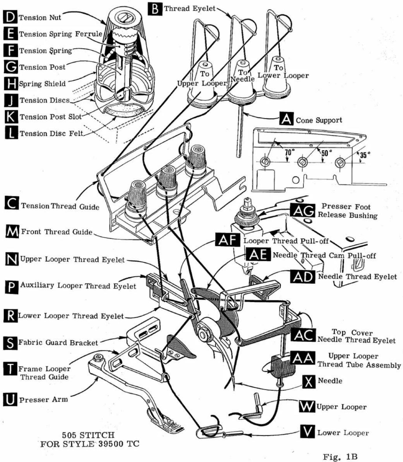
text_image
D Tension Nut E Tension Spring Ferrule F Tension Spring G Tension Post H Spring Shield J Tension Discs K Tension Post Slot L Tension Disc Felt B Thread Eyelet Upper Looper To Needle Lower Looper A Cone Support 70° 50° 35° C Tension Thread Guide M Front Thread Guide N Upper Looper Thread Eyelet P Auxiliary Looper Thread Eyelet R Lower Looper Thread Eyelet S Fabric Guard Bracket T Frame Looper Thread Guide U Presser Arm 505 STITCH FOR STYLE 39500 TC AF AE AD Presser Foot Release Bushing Top Cover Needle Thread Eyelet Upper Looper Thread Tube Assembly X Needle W Upper Looper V Lower Looper Fig. 1BPRESSER FOOT PRESSURE
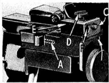
natural_image
Mechanical device with labeled parts A, B, C, D (no visible text or symbols)Fig. 2
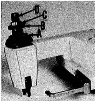
Sufficient presser foot pressure to feed work uniformly should be maintained. Should it be necessary to increase or decrease amount of pressure on presser foot, loosen lock nut (A, Fig. 2) and turn adjusting screw (B). Adjusting screw has a right hand thread, so tightening increases pressure, loosening decreases pressure. When pressure adjusting screw (B) has been properly set, tighten lock nut (A). With presser foot resting on throat plate, position locking nut (C) so that its under surface is approximately 1/32 to 1/16 inch (.79 mm to 1.59 mm) from the top surface of adjusting screw (B). Set cap (D) against locking nut (C).
FEED ECCENTRICS
Feed eccentrics used in these machines have been selected to produce approximately 14 stitches per inch on Styles 39500 QG, SD and TC, while on Style 39500 RN the eccentrics have been selected to produce approximately 9 stitches per inch. It will be noted on Styles 39500 QG, SD and TC, the part number of the main feed eccentric is No. 39540 B-14, while that of the differential feed eccentric is No. 39540 B-8. On Style 39500 RN the part number of the main feed eccentric is No. 39540 B-9, while that of the differential feed eccentric is No. 39540 B-7. Minor numbers of the part symbol indicate approximately the number of stitches obtainable when using that eccentric. Unless otherwise specified, machines will be shipped with above combinations of eccentrics.
Generally speaking, differential (right hand) feed eccentric determines number of stitches produced; main (left hand) feed eccentric is selected in relation to degree and direction of stretch of material being sewn, or type of operation.
Following stitch number feed eccentricis are available under No. 39540 B-4, 5, 6, 7, 8, 9, 10, 11, 12, 13, 14, 15, 16, 18, 20, 22, 24, 26, 28, 30, 32, 34, 36, 40, 50, 60, 70, 100. Only two eccentricis are supplied with each machine. Additional eccentrics may be ordered separately. To order an eccentric, use No. 39540 B with a minor number suffixed to indicate number of stitches desired. Example: "39540 B-14".
ASSEMBLING AND ADJUSTING SEWING PARTS
Before assembling and adjusting sewing parts, remove cloth plate, fabric guard, chip guard, upper knife assembly, lower knife holder assembly, hemming guide assembly; then follow this suggested sequence.
CLOTH PLATE REMOVAL AND ASSEMBLY
CAUTION: When removing the cloth plate (A, Fig. 3) loosen the cloth plate stud locking screw (B) and lift up cloth plate with the cloth plate stud (C) and cloth plate screw (D) assembled.
In assembly, the cloth plate screw and the cloth plate stud are tightened to the point of removing all play and yet turn in cloth plate. The cloth plate is then assembled to the machine with the flat and "V" slot of the cloth plate stud (C) towards the rear. Stud locking screw (B) is tightened securely which collapses the body of the stud to the screw (D) so that only the cloth plate will turn when opening or closing.

text_image
A B CFig. 3
SETTING THE NEEDLE
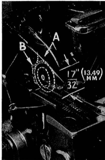
With throat plate assembled in position, needle should center in the front end of needle slot. When needle is at high position, needle point should be set 17/32 inch (13.49 mm) above throat plate (Fig. 4), for Styles 39500 QG, RN and SD. This dimension should be 1/2 inch (12.70 mm) for Style 39500 TC. To align needle or set the height above throat plate, move needle driving arm (A, Fig. 4) by loosening clamp screw (B). Remove throat plate, after needle has been set properly and clamp screw (B) has been tightened.
text_image
A BFig. 5
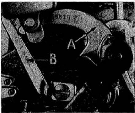
If needle thread cam pull-off (A, Fig. 5) overlaps looper thread pull-off (B), separate by moving looper thread pull-off back. When re-tightening looper pull-off screw, be sure to take up end play in needle driving arm.
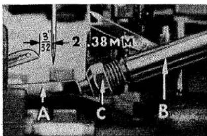
At this point, insert lower looper (A, Fig. 6) on Styles 39500 QG, SD and TC or lower spreader (A into bar (B). With lower looper or spreader at left end of its stroke, set looper or
text_image
A B 0 17" (13.49) 32 MMFig. 4
spreader point 3/32 inch(2.38 mm) from centerline of needle (Fig. 6 or 6A) using looper gauge No. 21225-3/32. Do not have lower looper or spreader deflecting needle. Tighten nut (C). Now assemble differential (front) feed dog.
SETTING THE REAR NEEDLE GUARD
Set rear needle guard (A, Fig. 7) as high as possible, without interfering with either lower looper or spreader or movement of lower knife holder, but still in position to deflect needle forward .002-.004 inch (.051-.102 mm). Screw (B) is used to set rear needle guard. Make sure there is no interference between rear needle guard and lower looper or spreader.
text_image
3/32 2.38MM A C BFig. 6

text_image
3/32 (2.38mm) A C BFig. 6A
SETTING THE LOWER LOOPER OR LOWER SPREADER
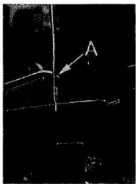
Now finish lower looper or spreader adjustment. As lower looper or spreader moves to the right, its point should be set into the needle scarf (A, Fig. 8) until the needle springs forward from rear needle guard surface another .002-.004 inch (.051-.102 mm).
SETTING THE FRONT NEEDLE GUARD
Assemble front needle guard (C, Fig. 7). When lower looper is springing needle off rear guard, set front needle guard as close as possible to needle without touching. Screw (D) is used to adjust and set front needle guard. After this setting, make sure there is no interference between the needle guards and differential feed dog.
SETTING THE UPPER LOOPER OR SPREADER
text_image
A C B DFig. 7
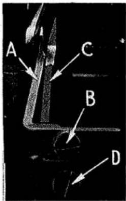
Insert upper looper (A, Fig. 9) or upper spreader in its holder. Screw (B) holds the upper looper or spreader in its holder, and permits the upper looper or spreader to be pushed in or out, or turned around its shank. Insert upper looper or spreader holder into shaft, if not already in place. Screw (C) in clamp collar holds upper looper or spreader holder in the shaft, and allows holder to be rotated or adjusted laterally.
When the upper looper or spreader is at the right end of its stroke, the upper looper or spreader holder should be set to
text_image
Black-and-white technical diagram with labeled arrow and letter A pointing to a vertical line or structureFig. 8
position the upper looper or spreader shank slightly back of vertical (Fig. 9). Top end of the upper looper or spreader shank should extend 1/32 to 1/16 inch (.79 to 1.59 mm) above the upper looper or spreader holder (Fig. 9) on Styles 39500 QG, SD and TC. This dimension should be 1/16 to 3/32 inch (1.59 to 2.38 mm) on Style 39500 RN.

text_image
C 32 to16 to1.59 mm B A BACK OF VERTICALFig. 9
As the upper looper or spreader moves from right to left, the point of the upper looper or the Vee notch of the spreader should pass just behind the eye of the lower looper, with approximately .002 inch (.051 mm) clearance between the upper looper or spreader and the lower looper (Fig. 10 or 10A).

text_image
.051mm) .002" CLEARANCEFig. 10
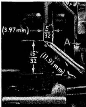
Turn the handwheel until the upper looper or spreader is at the left end of its travel. At this position, the point of the upper looper or the lower point of the upper spreader should extend about 5/32 inch (3.97 mm) to the left of centerline of the needle, for all Styles, also 1/2 inch (12.70 mm) above the top of the throat plate (Fig. 11) for Styles 39500 QG and SD; 33/64 inch (13.10 mm) above the top of the throat plate for Style 39500 RN and 15/32 inch (11.91 mm) for Style 39500 TC (Fig. 11A).
Now check the setting between upper spreader or upper looper and needle. If needle rubs the back of upper spreader or upper looper, pull spreader or looper out of its holder slightly and rotate holder forward a short distance. These same adjustments, in opposite movement, will reduce the clearance between the upper spreader or upper looper and needle. Reset to maintain dimensions of Fig. 10, 10A, 11 and 11A, as applicable.

text_image
(.051mm) 002 GECHARANCEFig. 10A
SETTING FEED DOGS
Now assemble main (back) feed dog (B, Fig. 12) and chaining feed dog (C). Set all feed dogs (A, B, C, Fig. 12) so the top surfaces of the teeth all lie in the same plane. This can be checked by sighting across the teeth with a straight edge. Now assemble throat plate. Feed dogs should now be leveled with throat plate surface by rotating feed tilting adjusting pin (D). This pin raises or lowers the back end of feed bar.
The feed dogs should be set level at the time the teeth first appear above throat plate. Screw (E) locks feed tilting adjusting pin (D) in place. Now set the main and differential feed dog teeth 3/64 inch (1.19 mm) above the throat plate, and chaining feed dog teeth flush with surface of throat plate.

text_image
5" 32 ←(3.97mm) A 1/2"(12.70mm)SETTING THE LOWER KNIFE
Fig. 11
Replace lower knife holder assembly. In replacing the lower knife holder assembly, tighten screw (A, Fig. 13) so that when the face of the flange on sleeve (B) seats against the throat plate mounting bracket (C) a free lateral motion of the lower knife and holder assembly is obtained when the knife is manually pressed at its upper corner. Lower knife (D) should be set with the cutting edge flush with the throat plate surface. Adjustments are made with hexagonal head screw which holds lower knife. Lower knife is spring pressed against upper knife. So no lateral adjustment is necessary when width of trim is changed.
text_image
(3.97mm) 5" / 32 15" / 32 (11.91mm) AFig. 11A
Lower knife may be secured in any position by tightening screw (E) against knife holder shaft.
Set the desired width of trim by measuring from the right edge of the lower knife to the needle, lock the lower knife holder shaft with screw (E).
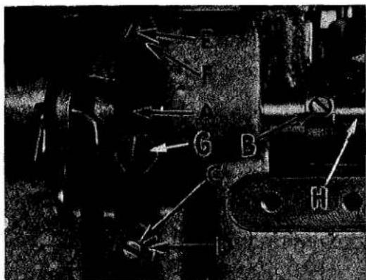
SETTING THE UPPER KNIFE
Replace upper knife assembly. Clamp upper knife (F, Fig. 13) in position, setting nut (G) to hold clamp (H) in its most clockwise position against upper knife. At
text_image
A B C D EFig. 12
bottom of its stroke, front cutting edge of upper knife should extend not less than 1/64 inch (.40 mm) below cutting edge of lower knife. The chain guard should be set down against the upper knife and slightly back from the cutting edge.
SETTING THE UPPER KNIFE (Continued)
After upper knife has been set for proper width of trim, screw (J) should be tightened to lock upper knife holding block (K) in place. This will simplify resetting when upper knife is replaced.

text_image
Labeled mechanical assembly diagram with numbered components and directional arrows indicating motion or assembly.Fig. 13
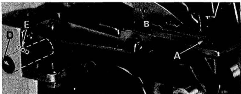
SETTING THE STITCH LENGTH
Length of stitch is determined by the combination of feed eccentrics used. Outer (left) eccentric (A, Fig. 14) actuates main (rear) feed dog; while the inner (right) eccentric (B) actuates the differential (front) feed dog.
In assembling feed eccentrics, be sure hubs are facing each other. Be careful not to damage shaft or key. Tighten nut (C) securely.
To change feed eccentricities, remove nut (C) and washer (D) from end of shaft (E). Turn handwheel in operating direction until key slot in eccentric is toward the front. Using hooked eccentric extractor (F), supplied with machine, reach behind eccentricities as shown and withdraw eccentricities. It may be necessary to move handwheel back and forth slightly during extraction.
If eccentrics are unusually tight fitting, in addition to removing nut (C, Fig. 15) and washer (D) from shaft (E), it may be helpful to remove nut (G) and feed driving connection (H). Then continue as originally suggested.
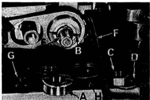
SETTING THE PRESSER FOOT
Assemble the presser foot to presser arm. With needle in high position, swing presser arm into sewing position and set the presser foot to align needle holes (front and back) and flat on throat plate. The front edge of needle hole in presser foot must be aligned with front edge of needle hole in throat plate. It is also important that the bottom of the presser foot be flat on the throat plate. If necessary, presser foot can be realigned with throat plate slots by shifting the foot lifter lever shaft (H, Fig. 16). To move the shaft, loosen collar screws (B, Fig. 16) and clamp screw (G) and then shift the foot lifter lever shaft to the left or right as required. Retighten collar screws and clamp screw.
The foot lifter lever arm (A, Fig. 16) and the collar (B) secure the shaft. Be sure the presser arm does not bind and rise when presser foot release bushing is unlocked.

text_image
A B C D E FFig. 14
Adjust lifter lever stop screw (C) so that presser foot can be raised no higher than the upper looper or spreader will permit; then lock the nut (D). There should be from 1/16 to 1/8 inch (1.59 to 3.17 mm) free motion of foot lifter lever before the presser foot begins to rise. This adjustment should be made with screw (E) and locked with nut (F). Re-assemble the chip guard, fabric guard and cloth plate. To assemble chip guard, turn handwheel until upper knife assembly reaches its highest position.
STARTING TO OPERATE
Be sure machine is threaded according to the threading diagram for your machine (Fig. 1, 1A or 1B).
With thread tensions light, set the lower looper thread eyelet (R, Fig. 1 and 1B) and the upper looper thread eyelet (N, Fig. 1A and 1B) approximately horizontal and in the middle of their front to back locations. Operate machine slowly, with presser foot in place; make sure chain forms and moves off stitch tongue freely.
NEEDLE THREAD CONTROL (503 STITCH)
While sewing on material, check needle thread control as follows: Usually all needle thread is drawn on needle down stroke. At top of needle stroke, thread should be just tight enough to feed chain off stitch tongue. Stitch tends to pull down slightly if excessive thread is pulled on the up stroke. With needle at bottom of stroke, position needle thread eyelet (AD, Fig. 1 or 1A) so that needle thread cam pull-off (AE) just contacts needle thread. To increase thread drawn on downstroke, position needle thread eyelet (AD, Fig. 1 or 1A) farther to the rear.
text_image
G B C D F AFig. 15
LOWER LOOPER THREAD CONTROL (503 STITCH, STYLES 39500 QG, SD and TC)
With material under presser foot, set lower looper thread eyelet (R, Fig. 1) back and down far enough so thread is a little slack when spreader reaches its extreme left position. Lower looper thread eyelet (R) should be about horizontal.
NOTE: If looper thread breakage occurs at high speed, move lower looper thread eyelet (R) upward slightly at an angle away from the needle thread arm binder screw.
text_image
G B HFig. 16
Frame looper thread guide (T) should be set with its eyelet approximately 1/8 inch (3.17 mm) to the right of heel eyelet of looper (V) at the time lower looper is at extreme left end of its travel.
THREAD TENSIONS (503 STITCH)
Before proceeding, balance both tensions to give a normal appearing stitch. Moderate change in these tensions will not markedly affect the purl.
UPPER LOOPER THREAD CONTROL (503 STITCH - STYLE 39500 RN)
With material under presser foot, set upper looper thread eyelet (N, Fig. 1A) back and down far enough so thread is a little slack when lower spreader reaches its extreme left position. Looper thread eyelet (N) should be about horizontal.
NEEDLE THREAD CONTROL (505 STITCH)
While sewing on material, check needle thread control as follows: About 60% of needle thread required for the stitch should be drawn on needle downstroke. To increase thread drawn on the downstroke, position needle thread eyelet (AD, Fig. 1B) farther to the rear.
LOWER LOOPER THREAD CONTROL (505 STITCH)
Set lower looper thread eyelet (R, Fig. 1B) about horizontal and all the way forward in its slot.
Frame looper thread guide (T) should be set with its eyelet approximately 1/8 inch (3.17 mm) to the right of lower looper (V) heel eyelet, when lower looper is at the left end of its stroke.
UPPER LOOPER THREAD CONTROL (505 STITCH)
With material under presser foot, set upper looper thread eyelet (N, Fig. 1B) to rest on top of lower looper thread eyelet (R), and back far enough so upper looper thread is a little slack when upper looper reaches the left end of its stroke.
POSITIONING THE SQUARE EDGE (505 STITCH)
Position of lower looper thread at the edge is located by balancing needle and upper looper thread tensions.
To reduce amount of lower thread in the stitch, or close the edge more, increase lower looper thread tension.

text_image
Technical diagram of a mechanical assembly with labeled parts A through GFig. 17
SETTING THE HEMMING GUIDE SUPPORT BRACKET (STYLE 39500 QG)
Assemble the hemming guide support bracket onto the lower knife support bracket by means of screw (A, Fig. 17). With the knurled adjusting screw (B), set the edge guide (C) so that the left side of its tip is even with and parallel to the right side of the right feed slot in the throat plate.
When the edge guide tip is in this position, the front or leading edge should be slightly to the right of parallel. This adjustment can be made by positioning the stop screw located towards the front of the hinge block and edge guide support bracket (D, Fig. 17).
Under normal conditions, the edge guide is spring pressed to compensate for the differences in material thickness. For example, as in going over seams. The amount of movement and pressure applied to the edge guide tip is controlled by adjusting the screw which presses against the spring located in the hinge block and edge guide support bracket (D, Fig. 17). Removing this spring and turning the screw all the way out against the edge guide prevents movement of the edge guide.
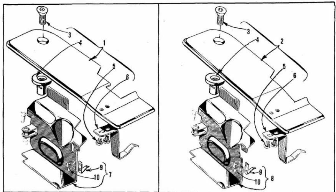
SETTING THE HEMMING GUIDE SUPPORT BRACKET (STYLE 39500 QG, Continued) Mount the retractable edge guide lever bracket (A, Fig. 18) onto the casting with
text_image
F D E H GFig. 18
screws (B). Attach the knee press chain to the lever arm (C) and the lever arm to the hemming guide support bracket with screw (D). The adjustable stop lever slide (E) should be positioned to the extreme left when in normal operation. The slide is moved to the right as shown in the illustration, only when making repairs on garments.
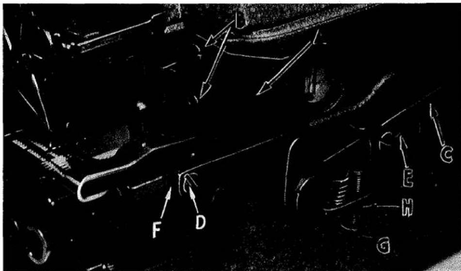
FINAL ADJUSTMENT OF HEMMING GUIDE (STYLE 39500 QG)
Adjust the edge guide (C, Fig. 17) by turning the knurled adjusting screw (B) so that the stitches are located in the folded edge, yet do not show on the face of the fabric. Adjust the overhanging guide (E) so that the space between its guiding edge and the edge guide corresponds with the thickness of the material to be hemmed. Adjust the stop screw (F) for the overhanging guide so that the tip of the overhanging guide is located at the center of the edge guide vertically. If desired, the overhanging guide can be locked into position by tightening the locking screw (G) located in the hinge block and edge guide support bracket (D).
Adjust the amount of retraction of the edge guide bracket (F, Fig. 18) by positioning the adjusting stop screw (G). The position of the screw will depend on the thickness of the seam to be crossed. The locking nut (H) should then be tightened into place.
SETTING THE HEMMING GUIDE SUPPORT BRACKET (STYLES 39500 RN, SD and TC)
Make sure that lock screw (A, Fig. 19) is loose, then proceed as follows:
Assemble the hemming guide support bracket onto the lower knife support bracket by means of screw (B, Fig. 19). With the knurled adjusting screw (C), set the edge guide (D) so that the left side of its tip is even with and parallel to the right side of the right feed slot in the throat plate.

text_image
Technical diagram of a mechanical device with labeled parts A, B, C, D, E, and FFig. 19
SETTING THE HEMMING GUIDE SUPPORT BRACKET (STYLES 39500 RN, SD and TC, Continued)
When the edge guide tip is in this position, the front or leading edge should be slightly to the right of parallel. This adjustment can be made by positioning the stop screw (A, Fig. 20) located towards the front of the hinge block and edge guide support bracket (E, Fig. 19).
text_image
Labeled diagram of a vehicle's front and rear components with numbered parts A through FFig. 20
Under normal conditions, the edge guide is spring loaded to compensate for the differences in the material thickness. For example, as in going over seams. The amount of movement and the pressure applied to the edge guide tip can be set by removing lock screw (B, Fig. 20) and adjusting the screw which presses against the spring and pin, located in the hinge block and edge guide support bracket (E, Fig. 19). Replace lock screw and tighten securely.
Fig. 20 If movement of the edge guide is not required, then remove lock screw (B, Fig. 20), set screw and spring; then replace set screw and lock screw. Be sure set screw is tightened against pin and lock screw is tightened against set screw.
FINAL ADJUSTMENT OF HEMMING GUIDE (STYLES 39500 RN, SD and TC)
Adjust the edge guide (D, Fig. 19) by turning the knurled adjusting screw (C) so that the stitches are located in the folded edge, yet do not show on the face of the fabric. At this point re-tighten screw (A, Fig. 19) securely.
Adjust the overhanging guide (F, Fig. 19) so that the space between its guiding edge and the edge guide (D) corresponds with the thickness of the material to be hemmed. Loosen set screw (C, Fig. 20) and holding screw (D), now move the hinge block (E) to obtain the proper distance between the edge guide and the overhanging guide. Re-tighten screws (C) and (D). Remove lock screw (F) and adjust stop screw that is in front of lock screw, so that the tip of the overhanging guide is located at the center of the edge guide vertically. Replace lock screw (F) and tighten against stop screw.
ORDERING REPAIR PARTS
ILLUSTRATIONS
This catalog has been arranged to simplify ordering repair parts. Exploded views of various sections of the mechanism are shown so that the parts may be seen in their actual position in the machine. On the page opposite the illustration will be found a listing of the parts with their part numbers, description and the number of pieces required in the particular view being shown.
Numbers in the first column are reference numbers only, and merely indicate the position of that part in the illustration. Reference number should never be used in ordering parts. Always use the part number listed in the second column.
ORDERING REPAIR PARTS (Continued)
Component parts of sub-assemblies which can be furnished for repairs are indicated by indenting their descriptions under the description of the main sub-assembly. Example:
| 11 | 39520 G | Presser Foot, for Style 39500 QG ----1 |
| 12 | 39520 H | Presser Foot, for Style 39500 SD ----1 |
| 13 | 39520 BH | Presser Foot, for Style 39500 RN ----1 |
| 14 | 39520 AX | Presser Foot, for Style 39500 TC ----1 |
| 15 | 39530 E | Presser Foot Chain Shield, for presser feet Nos.39520 G, 39520 H and 39520 AX ----1 |
| 15A | 39530 U | Presser Foot Chain Shield, for presser foot No.39520 BH ----1 |
| 16 | 22738 | Screw, for chain shield ----1 |
| 17 | 22768 B | Screw, for tongue and spring ----1 |
| 18 | 39530 | Presser Foot Hinge Spring ----1 |
| 19 | 39597 F | Stitch Tongue, marked "DV", for presser feet Nos.39520 G and 39520 AX ----1 |
| 19A | 39597 A | Stitch Tongue, marked "DS", for presser feet Nos.39520 H and 39520 BH ----1 |
| 20 | 22738 | Screw, for chip guard ----1 |
| 21 | 39530 B | Chip Guard ----1 |
It will be noted in the above example that the presser foot bottoms are not listed. The reason is that replacement of these parts individually is not recommended, so the complete assembly should be ordered.
Where the parts for all the styles covered in this catalog are not the same, the difference will be shown in the illustrations or mentioned in the descriptions. When a part is used in all machines covered by this catalog no machine style will be mentioned.
IDENTIFYING PARTS
Where the construction permits, each part is stamped with its part number. On some of the smaller parts, and on those where construction does not permit, an identification letter is stamped in to distinguish the part from similar ones.
PART NUMBERS REPRESENT THE SAME PART, REGARDLESS OF CATALOG IN WHICH THEY APPEAR.
USE GENUINE NEEDLES AND REPAIR PARTS
Success in the operation of these machines can be secured only with genuine UNION SPECIAL Needles and Repair Parts as furnished by the Union Special Corporation, its subsidiaries and authorized distributors. They are designed according to the most scientific principles, and are made with utmost precision. Maximum efficiency and durability are assured.
Genuine needles are packaged with labels marked Union Special®. Genuine repair parts are stamped with the Union Special trade mark. Each trade mark is your guarantee of the highest quality in materials and workmanship.
TERMS
Prices are net cash and subject to change without notice. All shipments are forwarded f.o.b. shipping point. Parcel post shipments are insured unless otherwise directed. A charge is made to cover postage and insurance.
text_image
Technical diagram showing mechanical assembly with numbered parts and directional arrows indicating motion or movement.
text_image
Technical diagram showing exploded view of mechanical components with numbered parts and assembly steps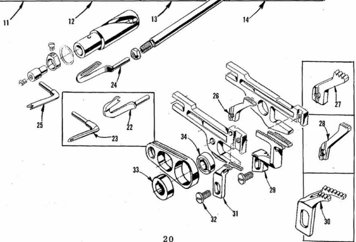
text_image
Exploded view diagram of a mechanical assembly with numbered parts and exploded viewsThe parts illustrated on pages 20, 22 and 24 and described on this page, page 23 and page 25 represent the parts that are used on Styles 39500 QG, RN, SD and TC, but not used on Style 39500 QA.
Unless otherwise specified in the description, the parts are used on all the machine styles covered in this catalog. Those parts shown in phantom views and bearing no reference numbers are common to Styles 39500 QA, QG, RN, SD and TC.
Use Catalog No. 103 QA (Style 39500 QA) for all parts not illustrated or described in this catalog.
Reference numbers that are inside a bracket on the picture plate and have indented descriptions, indicate they are component parts of a complete part or assembly.
| Ref.No. | PartNo. | Description | Amt.Req. |
| 1 | 39501 AP | Cloth Plate, for all Styles except 39500 TC | 1 |
| 2 | 39501 AS | Cloth Plate, for Style 39500 TC | 1 |
| 3 | 22657 D-12 | Screw, for cloth plate | 1 |
| 4 | 39501 K | Cloth Plate Stud | 1 |
| 5 | 22513 | Screw, for latch spring | 2 |
| 6 | 39532 D | Latch Spring | 1 |
| 7 | 39582 BR | Side Cover, for all Styles except 39500 TC | 1 |
| 8 | 39582 AR | Side Cover, for Style 39500 TC | 1 |
| 9 | 39582 H | Spring | 1 |
| 10 | 39582 J | Rivet | 2 |
| 11 | 39520 G | Presser Foot, for Style 39500 QG | 1 |
| 12 | 39520 H | Presser Foot, for Style 39500 SD | 1 |
| 13 | 39520 BH | Presser Foot, for Style 39500 RN | 1 |
| 14 | 39520 AX | Presser Foot, for Style 39500 TC | 1 |
| 15 | 39530 E | Presser Foot Chain Shield, for presser feet Nos. 39520 G,39520 H and 39520 AX | 1 |
| 15A | 39530 U | Presser Foot Chain Shield, for presser foot No. 39520 BH | 1 |
| 16 | 22738 | Screw, for chain shield | 1 |
| 17 | 22768 B | Screw, for tongue and spring | 1 |
| 18 | 39530 | Presser Foot Hinge Spring | 1 |
| 19 | 39597 F | Stitch Tongue, marked "DV", for presser feet Nos. 39520 Gand 39520 AX | 1 |
| 19A | 39597 A | Stitch Tongue, marked "DS", for presser feet Nos. 39520 Hand 39520 BH | 1 |
| 20 | 22738 | Screw, for chip guard | 1 |
| 21 | 39530 B | Chip Guard | 1 |
| 22 | 39560 B | Lower Spreader, for Style 39500 RN | 1 |
| 23 | 39508 A | Upper Looper, marked "CC", for Styles 39500 RN, 39500 TC(505 stitch) | 1 |
| 24 | 39508 B | Lower Looper, for all Styles except 39500 RN | 1 |
| 25 | 39560 A | Upper Spreader, marked "E", for Styles 39500 QG, SD and 39500 TC(503 stitch) | 1 |
| 26 | 39505 G | Chaining Feed Dog, marked "S", 20 t.p.i., for Styles 39500 QGand 39500 TC (503 stitch) | 1 |
| 27 | 39505 AL | Chaining Feed Dog, marked "CN", 16 t.p.i., for Style 39500 RN | 1 |
| 28 | 39505 H | Chaining Feed Dog, marked "U", 20 t.p.i., for Styles 39500 SDand 39500 TC (505 stitch) | 1 |
| 29 | 39526 H | Differential Feed Dog, 20 t.p.i., for all Styles except 39500 TC | 1 |
| 39526 AX | Differential Feed Dog, 16 t.p.i., for Style 39500 TC (505 stitch) | 1 | |
| 39526 AY | Differential Feed Dog, 20 t.p.i., for Style 39500 TC (503 stitch) | 1 | |
| 30 | 39505 BH | Main Feed Dog, marked "CM", 16 t.p.i., for Style 39500 RN | 1 |
| 31 | 39505 F | Main Feed Dog, marked "F", 20 t.p.i., for all Styles except39500 RN | 1 |
| 32 | 22528 | Screw, for main feed dog, for Style 39500 RN | 1 |
| - | 93 A | Screw, for main feed dog, for all Styles except 39500 RN | 1 |
| 33 | 39540 B-14 | Main Feed Driving Eccentric, for all Styles except 39500 RN | 1 |
| - | 39540 B-9 | Main Feed Driving Eccentric, for Style 39500 RN | 1 |
| 34 | 39540 B-8 | Differential Feed Driving Eccentric, for all Styles except 39500 RN | 1 |
| - | 39540 B-7 | Differential Feed Driving Eccentric, for Style 39500 RN | 1 |
text_image
Technical diagram of mechanical assembly with numbered parts and exploded views, likely for assembly or manufacturing purposes.THROAT PLATES, NEEDLE GUARDS, UPPER KNIFE, LOWER KNIFE PARTS AND MISCELLANEOUS PARTS
| Ref.No. | PartNo. | Description | Amt.Req. |
| 1 | 39592 AR-4 | Needle Thread Tension Spring----1 | |
| - | 39592 AR-4 | Looper Thread Tension Spring, for Styles 39500 QGand RN----1 | |
| - | 39592 AR-5 | Looper Thread Tension Spring, for Style 39500 SD----1 | |
| - | 39592 AR-4 | Looper Thread Tension Spring, for Style 39500 TC(505 stitch)----2 | |
| 2 | 39568 E | Auxiliary Upper Looper Thread Eyelet, for Styles39500 RN and TC----1 | |
| 3 | 39568 B | Upper Looper Thread Eyelet, for Style 39500 RN----1 | |
| - | 39568 B | Lower Looper Thread Eyelet, for all Styles except39500 RN----1 | |
| 4 | 39568 L | Upper Looper Thread Eyelet, for Style 39500 TC----1 | |
| 5 | 39563 J | Needle Thread Cam Pull-off----1 | |
| 6 | 39556 M | Chain Cutting Knife----1 | |
| 7 | 22798 | Screw, for chain cutter blade----1 | |
| 8 | 39556 L | Chain Cutter Blade----1 | |
| 9 | 605 | Screw, for chain cutting knife----2 | |
| 10 | 39570 L | Upper Knife, for Style 39500 RN----1 | |
| 10A | 39570 | Upper Knife, for all Styles except 39500 RN----1 | |
| 11 | 39578 V | Fabric Guard, for Style 39500 RN----1 | |
| 11A | 39578 R | Fabric Guard, for all Styles except 39500 RN----1 | |
| 12 | 39556 N | Presser Foot Tilt Lever, for Style 39500 RN----1 | |
| 13 | 22561 | Screw, for presser foot tilt lever, for Style 39500 RN - 2 | |
| 14 | 39525 K | Needle Guard, rear, for Style 39500 RN----1 | |
| 15 | 39524 D | Throat Plate, marked "AM", for Styles 39500 RNand SD----1 | |
| 16 | 39524 G | Throat Plate, marked "AF", for Style 39500 QG----1 | |
| 17 | 39525 E | Needle Guard, rear, for all Styles except 39500 RN----1 | |
| 18 | 39582 BS | Oil Shield, for all Styles except 39500 TC----1 | |
| 19 | 22585 G | Screw, for oil shield and locking side cover----1 | |
| 20 | 39525 D | Needle Guard, front----1 | |
| 21 | 90 | Screw, for needle guards----2 | |
| 22 | 39580 BA | Throat Plate and Lower Knife Support Bracket,for all Styles except 39500 TC----1 | |
| 23 | 88 B | Screw, for lower knife holder----1 | |
| 24 | 39550 T | Lower Knife Holder, for all Styles except 39500 TC----1 | |
| - | 39550 V | Lower Knife Holder, for Style 39500 TC----1 | |
| 25 | 39550 K | Spring Cover----1 | |
| 26 | 39550 J | Knife Pressure Equalizing Spring----1 | |
| 27 | 22559 H | Adjusting Screw----1 | |
| 28 | 39524 AX | Throat Plate, marked "CD", for Style 39500 TC(505 stitch)----1 | |
| 29 | AS22 D | Screw, for throat plate, for Style 39500 TC----1 | |
| - | 22524 | Screw, for throat plate, for all Styles except39500 TC----1 | |
| 30 | 39524 AY | Throat Plate, marked "CE", for Style 39500 TC(503 stitch)----1 | |
| 31 | 39580 AG | Throat Plate and Lower Knife Support Bracket, forStyle 39500 TC----1 | |
| 32 | 39580 E | Throat Plate and Lower Knife Support Bracket Shim,for Style 39500 TC----1 |

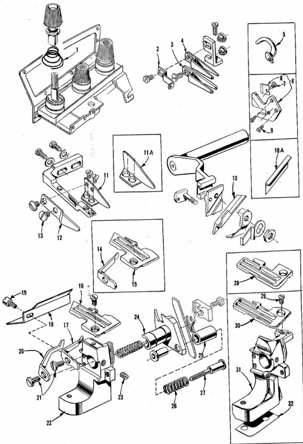
text_image
Technical diagram of mechanical assembly with numbered parts and exploded views, likely from an engineering manual.HEMMER GUIDES ASSEMBLIES, OVERHANGING GUIDES AND OPERATING LEVER ASSEMBLY
| Ref.No. | PartNo. | Description | Amt.Req. |
| 1 | 29481 L | Hemmer Guide Assembly, for Styles 39500 RN, SD and TC | 1 |
| 2 | 303 | Screw, for edge guide support | 1 |
| 3 | 61303 D | Cup Washer, for screw No. 303 | 1 |
| 4 | 39589 AC | Hemming Attachment Base | 1 |
| 5 | 22873 C | Adjusting Screw, for edge guide support | 1 |
| 6 | 39589 AD | Edge Guide Support | 1 |
| 7 | 22799 B | Hinge Screw, for overhanging guide hinge block | 1 |
| 8 | 22743 | Screw, for edge guide tension spring | 2 |
| 9 | 222 D | Screw, for hemmer guide end plate | 1 |
| 10 | 39589 AF | Hemmer Guide End Plate | 1 |
| 11 | HA73 B | Stop Screw, for overhanging guide hinge block | 2 |
| 12 | 73 C | Set Screw, for No. 22729 A | 1 |
| 13 | 39589 AB | Hinge Block | 1 |
| 14 | 39589 AJ | Hemmer Guide Stop | 1 |
| 15 | 22729 A | Screw, for hemmer guide stop | 1 |
| 16 | 39503 L | Edge Guide | 1 |
| 17 | 22513 C | Screw, for edge guide | 1 |
| 18 | 39589 AG | Sleeve, for edge guide | 1 |
| 19 | 39589 AA | Overhanging Guide Hinge Block | 1 |
| 20 | 39589 AH | Holding Spring | 1 |
| 21 | 79077 | Stop Screw, for edge guide | 1 |
| 22 | 39568 J | Spring, for edge guide tension | 1 |
| 23 | 39589 AL | Pin, for edge guide tension spring | 1 |
| 24 | 222 D | Screw, for overhanging guide | 1 |
| 25 | 39589 AK-1/2 | Overhanging Guide, for 1/2 inch hem, for Styles 39500 SD, TC | 1 |
| 26 | 39589 AK-3/4 | Overhanging Guide, for 3/4 inch hem, for Styles 39500 SD, TC | 1 |
| 27 | 39589 AK-1 | Overhanging Guide, for 1 inch hem, for Styles 39500 SD, TC | 1 |
| 28 | 39589 AE-1/2 | Overhanging Guide, for 1/2 inch hem, for Style 39500 RN | 1 |
| 29 | 39589 AE-3/4 | Overhanging Guide, for 3/4 inch hem, for Style 39500 RN | 1 |
| 30 | 39589 AE-1 | Overhanging Guide, for 1 inch hem, for Style 39500 RN | 1 |
| 31 | 39589 H-3/4 | Overhanging Guide, for 3/4 inch hem, for Style 39500 QG | 1 |
| 32 | 39589 H-1 | Overhanging Guide, for 1 inch hem, for Style 39500 QG | 1 |
| 33 | 39589 H-1/2 | Overhanging Guide, for 1/2 inch hem, for Style 39500 QG | 1 |
| 34 | 98 A | Screw, for overhanging guide, for Style 39500 QG | 1 |
| 35 | 29481 F | Hemming Guide Assembly, for Style 39500 QG | 1 |
| 36 | 39589 U | Hemming Guide Hinge Spring | 1 |
| 37 | 22760 A | Screw, for edge guide | 1 |
| 38 | 39503 G | Edge Guide | 1 |
| 39 | 22565 C | Screw | 2 |
| 40 | 39568 J | Edge Guide Tension Spring | 1 |
| 41 | 79077 | Screw | 2 |
| 42 | 22738 | Screw | 2 |
| 43 | 28-176 Blk. | Adjustable Insert Blank | 1 |
| 44 | 39589 E | Overhanging Guide Base | 1 |
| 45 | 39589 J | Spring | 1 |
| 46 | 22873 B | Adjusting Screw | 1 |
| 47 | 22743 | Screw | 1 |
| 48 | 22799 E | Hinge Screw | 1 |
| 49 | 39589 G | Hinge Block and Edge Guide Support | 1 |
| 50 | 39589 F | Overhanging Guide Hinge | 1 |
| 51 | 77 Q | Screw | 1 |
| 52 | 22569 C | Screw, for operating lever assembly, for Style 39500 QG | 2 |
| 53 | 8372 A | Washer, for screw No. 22569 C | 2 |
| 54 | 22593 | Screw, for hemming guide assembly | 1 |
| 55 | 29481 E | Operating Lever Assembly, for Style 39500 QG | 1 |
| 56 | 39589 M | Operating Lever Bracket | 1 |
| 57 | 36279 B | Spring | 1 |
| 58 | 9937 | Nut | 1 |
| 59 | 22874 | Screw | 1 |
| 60 | 39589 K | Operating Lever | 1 |
| 61 | 22726 A | Screw | 1 |
| 62 | 39589 N | Operating Lever Slide Member | 1 |
| 63 | 22557 D | Screw | 1 |
| 64 | 61256 G | Washer | 1 |
| 65 | 39589 L | Operating Lever Link | 1 |
| 66 | 22760 A | Screw, for operating lever link, for Style 39500 QG | 1 |
Union Special Wants to Help You Cut Sewing Machine Maintenance Costs
Union Special is offering two practical systems to help pinpoint and reduce your sewing machine maintenance costs: a record keeping system to help spot machines requiring abnormally high maintenance, and a parts inventory system to speed routine repairs.
Machine Maintenance Records
Repair-prone machines or inexperienced competent operators can eat up your maintenance dollars in short order. To help spot these problems, Union Special suggests two variations of a simple maintenance record keeping system using cards provided by Union Special.
The first system utilizes a "Machine Maintenance Record" card (Form 237) for each sewing machine in a plant. When a repair is required, the card is pulled from the file and the repair date, parts used, and their cost are entered in the spaces provided and the card is refiled.
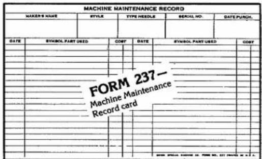
text_image
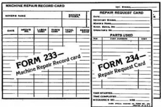
MACHINE MAINTENANCE RECORD MAKERS NAME STYLE TYPE NEEDLE SERIAL NO. DATE PURCH. DATE SYMBOL PART USED COST DATE SYMBOL PART USED COST FORM 237- Machine Maintenance Record cardThe second system is normally used when more detailed information on repair costs is desired. Two record cards are used: a "Repair Request Card" (Form 234), and a "Machine Repair Record" (Form 233). When a machine requires service, the forelady or foreman fills out the top of a "Repair Request Card" and gives it to a mechanic. He fills in the time the repair work is started, the parts used and their cost,
and the completion time. This data is then transferred to the permanent "Machine Repair Record" kept in the office.
Whichever system is used, management now has an invaluable tool to reduce needless maintenance costs.
Repair Part Inventories
While record keeping tells management which machines require abnormally high maintenance, it does little to help reduce the downtime caused by routine repairs. To alleviate this situation, Union Special recommends that manufacturers establish a formal parts inventory system for each type of sewing machine they operate.
Excessive machine downtime and wasted hours by mechanics can be eliminated with an orderly in-plant inventory of the most commonly needed parts. There is no longer a need to cannibalize other machines for spare parts. Long waits for deliveries are avoided and machine downtime is kept to a minimum. The cost of a parts inventory is small when the overall savings are considered.
text_image
MACHINE REPAIR RECORD CARD MAKERS NAME DATE MARKS NAME LARGE COUNT PARTS COUNT TOTAL COUNT REVEE COUNT REPAIR REQUEST CARD DATE INVOICE BY: MACHES NAME: MACHES NAME: ORDER BY: NO. OVERFORD NO. PARTS USED ITEM PART NUMBER COUNT FORM 233- Machine Repair Record card FORM 234- Repair Request Card TIME STARTED. TIME COMPLETED. RECEIVED NO. .... HBS HOT: SPECIAL ORDER IN PART NO. 01 HOT: SPECIAL ORDER IN PART NO. 01For free sample copies of the machine record cards and spare part inventory lists for a variety of the most popular machines, contact your local Union Special Representative or write direct to Union Special.
U. Union Special® Industrial Sewing Equipment
Style 39500 QG
Suggested Minimum Spare Parts List*
| Part Number | Description | Minimum Quantity Per 5 Machines | Part Number | Description | Minimum Quantity Per 5 Machines |
| 39520 G | Presser foot | 1 | 39525 D | Needle guard front | 1 |
| 39505 F | Main feed dog | 1 | 39525 E | Needle guard rear | 1 |
| 93 A | Screw for main feed dog | 2 | 90 | Screw for needle guards | 2 |
| 39526 H | Differential feed dog | 1 | 39551 F | Needle clamp stud | 2 |
| 22528 | Screw for differential feed dog | 2 | 14077 | Needle clamp nut for stud | 2 |
| 39505 G | Chaining feed dog | 1 | 22596 E | Screw for needle drive arm | 1 |
| 22797 A | Screw for chaining feed dog | 2 | 39570 | Upper knife | 2 |
| 39524 G | Throat plate | 1 | 39549 | Lower knife | 2 |
| 22524 | Screw for throat plate | 4 | 22588 A | Screw for lower knife | 2 |
| 154 GAS | Needles | 200 | 21225 3/32 | Looper gauge | 1 |
| 39508 B | Looper lower | 1 | 29484 | Screw assortment | 1 |
| 39560 A | Spreader upper | 1 |

natural_image
World map with latitude and longitude grid lines, showing continents and oceans (no text or labels)WORLDWIDE SALES AND SERVICE
Union Special Corporation maintains sales and service facilities throughout the world. These offices will aid you in the selection of the right sewing equipment for your particular operation. Union Special Corporation representatives and service technicians are factory trained and are able to serve your needs promptly and efficiently. Whatever your location, there is a qualified representative to serve you.
Corporate Office:
One Union Special Plaza
Huntley, IL 60142
Phone: 708·669·5101
Fax: 708·669·1096
European Distribution Center:
Union Special GmbH
Raiffeisenstrasse 3
D-71696 Möglingen, Germany
Tel: 49·07141·247·0
Fax: 49·7141·247·100
Brussels, Belgium
Charlotte, N.C.
Commerce, CA
El Paso, TX
Hong Kong, China
Huntley, IL
Leicester, England
Lille, France
Miami, FL
Milan, Italy
Mission, TX
Möglingen, Germany
Montreal, Quebec
Osaka, Japan
Other Representatives throughout
all parts of the world.

Finest Quality
Union Special® INDUSTRIAL SEWING EQUIPMENT