29480AWB - Sewing machine Union Special - Free user manual and instructions
Find the device manual for free 29480AWB Union Special in PDF.

User questions about 29480AWB Union Special
0 question about this device. Answer the ones you know or ask your own.
Ask a new question about this device
Download the instructions for your Sewing machine in PDF format for free! Find your manual 29480AWB - Union Special and take your electronic device back in hand. On this page are published all the documents necessary for the use of your device. 29480AWB by Union Special.
USER MANUAL 29480AWB Union Special
Second Edition Copyright 1996 by Union Special Corporation Rights Reserved in All Countries Printed in U.S.A. May 1996

natural_image
Technical line drawing of a mechanical assembly with mounting flanges and bolts (no text or symbols)PREFACE
This Engineer's Manual has been designed to assist you in adjusting under bed thread trimmer assembly 29480AWB.
It is the desire of Union Special that each machine run in its optimum performance. Adjustments listed in this manual are designed specifically for your machine and are written with utmost percision to assure long lasting service.
This manual has been comprised on the basis of available information. Changes in design and/or improvements may incorporate a slight modification of configuration in illustrations or adjustments.
SAFETY RULES
- Before putting the machines described in this manual into service, carefully read the instructions. The starting of each machine is only permitted after taking notice of the instructions and by qualified operators.
IMPORTANT! Before putting the machine into service, also read the safety rules and instructions from the motor supplier.
-
Observe the national safety rules valid for your country.
-
The sewing machines described in this instruction manual are prohibited from being put into service until it has been ascertained that the sewing units which these sewing machines will be built into, have conformed with the EC Council Directives (89/392/EEC, Annex II B).
Each machine is only allowed to be used as foreseen. The foreseen use of the particular machine is described in paragraph "STYLES OF MACHINES" of this instruction manual. Another use, going beyond the description, is not as foreseen.
-
All safety devices must be in position when the machine is ready for work or in operation. Operation of the machine without the appertaining safety devices is prohibited.
-
Wear safety glasses.
-
In case of machine conversions and changes all valid safety rules must be considered. Conversions and changes are made at your own risk.
-
The warning hints in the instructions are marked with one of these two symbols:

- When doing the following the machine has to be disconnected from the power supply by turning off the main switch or by pulling out the main plug:
8.1 When threading needle(s), looper, spreader etc.
8.2 When replacing any parts such as needle(s), presser foot, throat plate, looper, spreader, feed dog, needle guard, folder, fabric guide etc.
8.3 When leaving the workplace and when the workplace is unattended.
8.4 When doing maintenance work.
8.5 When using clutch motors without actuation lock, wait until the motor is stopped totally.
-
Maintenance, repair and conversion work (see item 8) must be done only by trained technicians or special skilled personnel under consideration of the instructions.
-
Any work on the electrical equipment must be done by an electrician or under direction and supervision of special skilled personnel.
- Work on parts and equipment under electrical power is not permitted. Permissible exceptions are described in the applicable sections of standard sheet DIN VDE 0105.
- Before doing maintenance and repair work on the pneumatic equipment, the machine has to be disconnected from the compressed air supply. In case of existing residual air pressure after disconnecting from compressed air supply (i.e. pneumatic equipment with air tank), the pressure has to be removed by bleeding.
THREADING DIAGRAM
LOOPER THREAD STRIKE-OFF
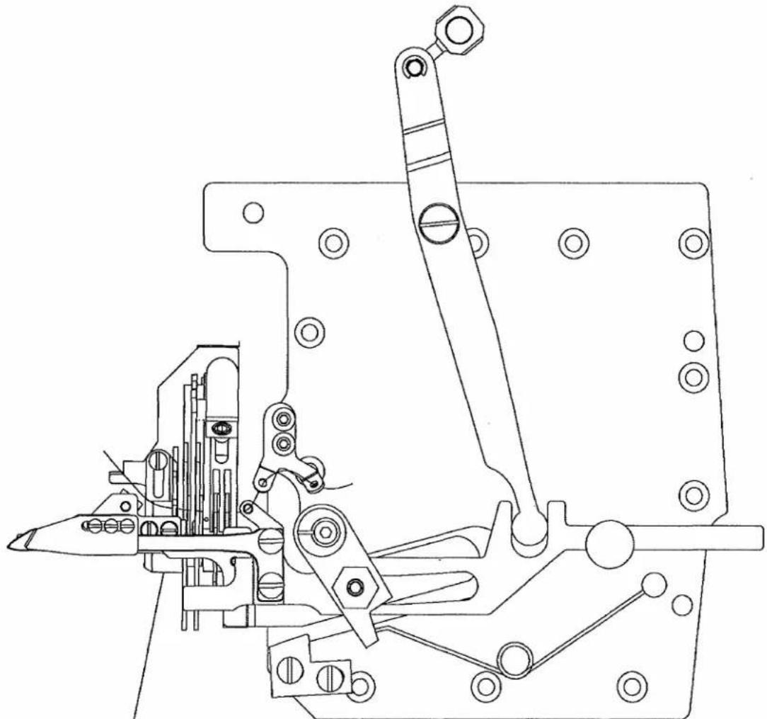
natural_image
Technical line drawing of a mechanical assembly with no visible text or symbolsCAUTION:
IMPROPER THREADING MAY CAUSE;
LOOPER THREAD WRAP-UPS OR INCONSISTENT START OF STITCHES
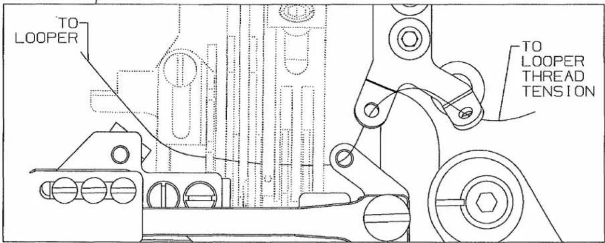
text_image
TO LOOPER TO LOOPER THREAD TENSIONSTANDARD ADJUSTMENTS
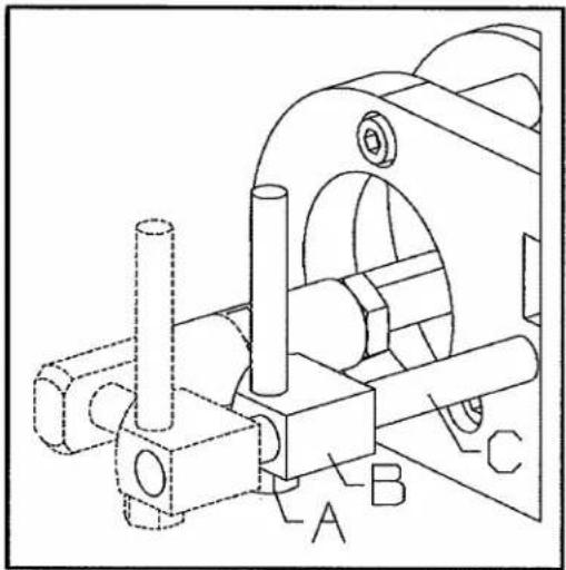
UNDER BED THREAD TRIMMER
Set stroke of the driving solenoid to:
45/64" (18mm). All gauges.

text_image
45/64" (18mm) All GaugesADJUSTING PROCEDURES
Remove the cloth plate.
Loosen nut (A).
Move crosshead (B) on shaft (C) as required.
Retighten nut (A).
natural_image
Technical line drawing of a mechanical assembly with labeled components A, B, and C (no text or symbols beyond labels)RESULTS OF IMPROPER ADJUSTMENTS
Will not trim thread.
Will create interference with looper.
STANDARD ADJUSTMENTS
UNDER BED THREAD TRIMMER ASSEMBLY
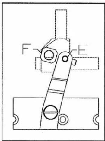
When the thread trimmer is in its home position, the distance between edge (AA) and the protruding edge of lever (D) should be:
1/64" (0.4mm).
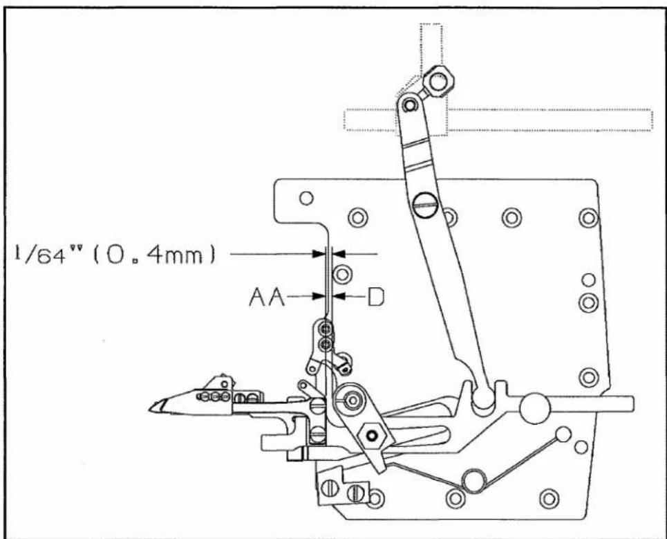
text_image
1/64" (0.4mm) AA DADJUSTING PROCEDURES
Remove retainer (E).
Turn carrier bolt (F) in or out as required.
Replace retainer (E).
text_image
F ERESULTS OF IMPROPER ADJUSTMENTS
Excessive wear of mechanism.
Part breakage.
Parts fall off.
STANDARD ADJUSTMENTS
UNDER BED THREAD TRIMMER AS-SEMBLY
KNIFE ADJUSTMENT
When positioning lower knife (G), eyelet (J) must be seated to the right.
Lower knife (G) must be seated to the right and all the way forward when tightened.

text_image
Knife Extended G H J TORQUE: 14in.1bs. (1.6Nm) To Touch K SeatedADJUSTING PROCEDURES
Loosen 2 screws (K).
Move eyelet (J) to the right as required.
Retighten screws (K).
To ensure no binds, extend knife (G) to the left and loosen upper knife screws (H) at the same time.
Retighten screws (H).
RESULTS OF IMPROPER ADJUSTMENTS
Interference with spring clamp.
Trimming failure.
Binding condition.
STANDARD ADJUSTMENTS
UNDER BED THREAD TRIMMER ASSEMBLY
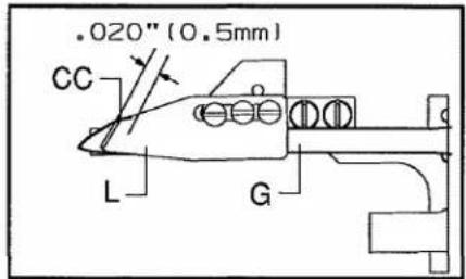
Upper knife (L) should overlap lower knife (G) by:
.020" (0.5mm).
The distance from clamping leaf spring (N) to the tip of lower knife (G) should be:
1/8" (3mm). Clamping leaf spring (N) should be flush with knife at edge (BB).
NOTE: The clamping leaf spring must be set to only clamp the looper thread, NOT the needle threads.
The distance from tension leaf spring (M) to the back of upper knife (L, @ point CC) should be:
.020" (0.5mm).
text_image
.020" (0.5mm) CC L G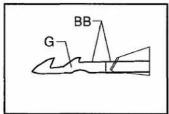
text_image
G BB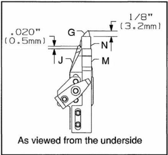
text_image
"020" (0.5mm) G 1/8" (3.2mm) J N M As viewed from the undersideADJUSTING PROCEDURES
UPPER KNIFE AND CLAMPING SPRING
Loosen two screws (H) and screw (H1).
Move upper knife (L) and clamping leaf spring (N) left to right as required.
Retighten screws (H) and (H1).
TENSION SPRING
Loosen two screws (P).
Adjust leaf spring (M) left to right as required.
Retighten screws (P).
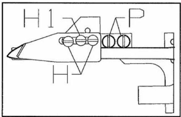
text_image
H 1 P HRESULTS OF IMPROPER ADJUSTMENTS
Trimming failures.
Thread breakage.
Improper starting.
STANDARD ADJUSTMENTS
UNDER BED THREAD TRIMMER ASSEMBLY
With the needles at top dead center:
Lower knife (G) should extend past the end of looper (Q) by:
15/32" (12.0mm).
The tip of lower knife (G) should be centered front to back, to the rear edge of the flat on top of looper (Q).
Stop (R) sets the distance of the upper knife and springs to the looper, it should be centered in its slots.
Guide (S) should just contact edge (DD) of knife mechanism.
On cover stitch machines knife (G) should be set slightly rearword .005" (.10mm) of the standard adjustment.
The bottom of upper knife (L) should clear looper (Q) by:
.004" (0.1mm).
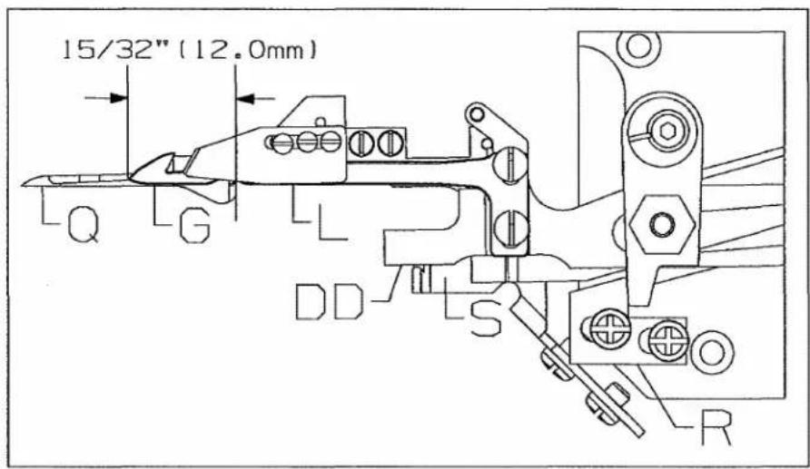
text_image
15/32" (12.0mm) Q G L DD S R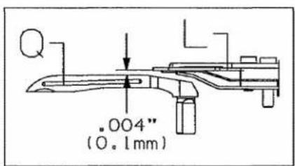
text_image
.004" (0.1mm)ADJUSTING PROCEDURES
Move eccentric (U) as required.
Retighten screw (T).
STOP DISTANCE
Loosen screws (V).
Move stop (R) as required.
Retighten screws (V).
GUIDE DISTANCE
Loosen screws (W).
Move guide (S) as required to just contact edge (DD).
Retighten screws (W).
Loosen screws (W). Move guide (S) as required to obtain .004" (0.1mm) dimension.
Retighten screws (W)

text_image
Technical diagram of a mechanical assembly with labeled components U, T, W, VRESULTS OF IMPROPER ADJUSTMENTS
Trimming failures.
Thread breakage.
Improper starting.
STANDARD ADJUSTMENTS
UNDER BED THREAD TRIMMER
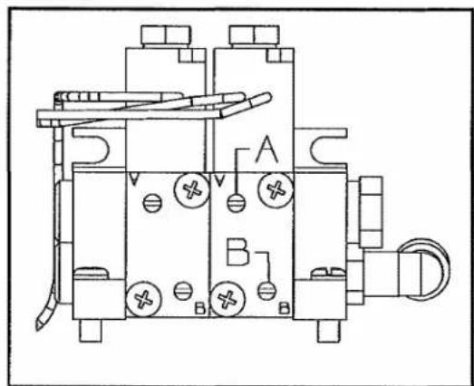
ELECTROPNEUMATIC DRIVE
Adjust the metering screws so that thread trimmer mechanism and knife move smoothly left to right and the threads are cleanly cut and clamped.
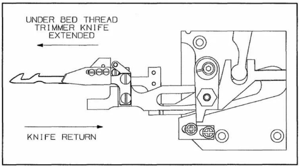
text_image
UNDER BED THREAD TRIMMER KNIFE EXTENDED KNIFE RETURNADJUSTING PROCEDURES
To increase the speed of the knife return, turn screw (A) counterclockwise.
To decrease the speed of the knife return, turn screw (A) clockwise.
To increase the speed of extending the knife, turn screw (B) counterclockwise.
To decrease the speed of extending the knife, turn screw (B) clockwise.
text_image
Technical diagram of an electrical component with labeled parts A and B, showing internal components and connections.RESULTS OF IMPROPER ADJUSTMENTS
Excessive wear on mechanism. Incomplete stroke of mechanism.
text_image
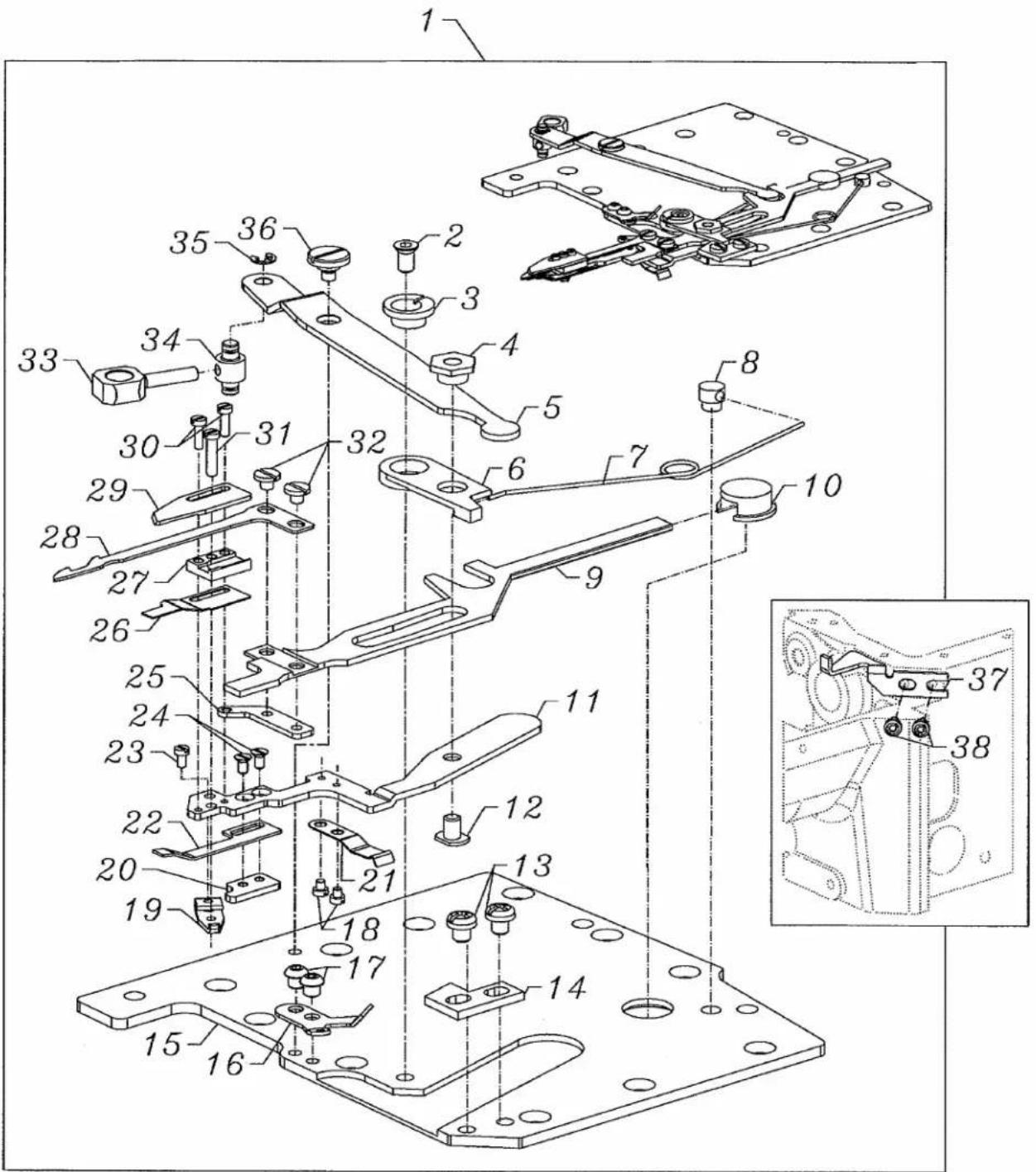
Technical diagram of a mechanical assembly with numbered components, likely an engine or assembly component.FIGURE 2 - UNDER BED THREAD TRIMMER ASSEMBLY
| Ref.No. | Part No. | Description | Amt.Req. |
| 1. | 29480AWB | Looper Thread Undertrimmer Assembly | 1 |
| 2. | 18-1450 | Screw | 1 |
| 3. | 34768A | Eccentric Guide | 1 |
| 4. | 34768C | Guide Washer | 1 |
| 5. | 34763P | Lever | 1 |
| 6. | 34750R | Lever | 1 |
| 7. | 34763N | Spring | 1 |
| 8. | 34751MS | Pin | 1 |
| 9. | 34750T | Lower Knife Holder | 1 |
| 10. | 34750U | Guide | 1 |
| 11. | 34750SA | Upper Knife Holder | 1 |
| 12. | 18-1472 | Screw | 1 |
| 13. | 18-1449 | Screw | 2 |
| 14. | 34775H | Stop | 1 |
| 15. | 34382AC | Oil Reserve Cover | 1 |
| 16. | 50366D | Looper Thread Guide | 1 |
| 17. | 18C1471 | Screw | 2 |
| 18. | SM6020250TP | Screw | 2 |
| 19. | 34751MT | Tension Lever | 1 |
| 20. | 34769B | Threaded Plate | 1 |
| 21. | 34773E | Leaf Spring | 1 |
| 22. | 34773D | Leaf Spring | 1 |
| 23. | 18-1473 | Screw | 1 |
| 24. | SM1020450TP | Screw | 2 |
| 25. | 50368AE | Threaded Plate | 1 |
| 26. | 34773F | Leaf Spring | 1 |
| 27. | 34750P | Lower Knife Guide | 1 |
| 28. | 34749P | Lower Knife | 1 |
| 29. | 34770M | Upper Knife | 1 |
| 30. | SM6020600TP | Screw | 2 |
| 31. | SM6021000TP | Screw | 1 |
| 32. | 18-1453 | Screw | 2 |
| 33. | 34752M | Driving Link | 1 |
| 34. | 34752N | Carrier Bolt | 1 |
| 35. | RE0250000K0 | E-Ring | 1 |
| 36. | SD0600176SP | Screw | 1 |
| 37. | 34794A | Guide | 1 |
| 38. | 90 | Screw, for guide | 2 |
NOTES
NOTES

natural_image
World map with latitude and longitude grid lines, showing continents and oceans (no text labels)WORLDWIDE SALES AND SERVICE
Union Special Corporation maintains sales and service facilities throughout the world. These offices will aid you in the selection of the right sewing equipment for your particular operation. Union Special Corporation representatives and service technicians are factory trained and are able to serve your needs promptly and efficiently. Whatever your location, there is a qualified representative to serve you.
Corporate Office:
One Union Special Plaza
Huntley, IL 60142
Phone: 847·669·5101
Fax: 847·669·1096
European Distribution Center:
Union Special GmbH
Raiffeisenstrasse 3
D-71696 Möglingen, Germany
Tel: 49-07141-247-0
Fax: 49·7141·247·100
Brussels, Belgium
Charlotte, N.C.
El Paso, TX
Hong Kong, China
Huntley, IL
Leicester, England
Lille, France
Miami, FL
Milan, Italy
Möglingen, Germany
Montreal, Quebec
Osaka, Japan
Santa Fe Springs, CA
Other Representatives throughout all parts of the world.

Finest Quality
Union Special®
INDUSTRIAL SEWING EQUIPMENT