100LS - Sewing machine Union Special - Free user manual and instructions
Find the device manual for free 100LS Union Special in PDF.

User questions about 100LS Union Special
0 question about this device. Answer the ones you know or ask your own.
Ask a new question about this device
Download the instructions for your Sewing machine in PDF format for free! Find your manual 100LS - Union Special and take your electronic device back in hand. On this page are published all the documents necessary for the use of your device. 100LS by Union Special.
USER MANUAL 100LS Union Special
ADJUSTING INSTRUCTIONS AND ILLUSTRATED PARTS LIST
100P
100S
100LS
100TN
100NTN
CLASS 100 STREAMLINE HIGH SPEED SADDLE STITCH MACHINE
CATALOG
NO. 122L
SECOND
EDITION
Catalog No. 122 L
LIST OF PARTS AND INSTRUCTIONS
FOR
OPERATING AND ADJUSTING
CLASS 100
STREAMLINED SADDLE STITCH MACHINE
Styles 100 P 100 LS 100 S 100 TN 100 NTN
Second Edition
© 1962
By
Union Special Corporation
Rights Reserved in All Countries
INDUSTRIAL SEWING MACHINES
CHICAGO
Printed in U.S.A
April, 1981
FOREWARD
The dominating idea back of Union Special is to build the best industrial sewing machines in the world. The high speed streamlined saddle stitch machines are a pronounced achievement along these lines. All parts are made to precision gauges insuring complete interchangeability. A few of the outstanding features are:
- Streamlined design. Pleasing in appearance, this natural functional design provides greater stability and ruggedness, free from difficult-to-clean recesses.
- Simplified oiling. Automatically supplies oil to lower main shaft bearings, feed rocker and feed lift bearings.
- Acceleration. The machine is brought to top speed in an instant - for higher productive rates and lower costs.
- Push button control, for quick, easy adjustment of stitch length, with a stitch length indicator of the comparison type, using letters as a means of reference, to predetermine stitch lengths.
It is our constant aim to furnish carefully prepared information that will enable the customer to secure all possible economies and advantages from the use of UNION SPECIAL machines. The following pages contain valuable operating and adjusting data and illustrate and describe the parts for Styles in Class 100 streamlined saddle stitch machines.
Union Special representatives will be found in all manufacturing centers, ready to cooperate with you to plan and estimate requirements.
Engineering Department
APPLICATION OF CATALOG
This catalog applies only to the standard styles of machines as listed herein. All references to directions, such as right and left, front and back, etc., are taken from the operator's position while seated at the machine. The direction of rotation of the handwheel is toward the operator.
IDENTIFICATION OF MACHINE
Each UNION SPECIAL machine carries a style number which is stamped in the name plate on the machine. Style numbers are classified as standard and special. Those which are standard have one or more letters suffixed, but never contain the letter "Z". Example: "100 LS". Style numbers containing the letter "Z" are special.
Styles of machines similar in construction are grouped under a class number which differs from the style number in that it contains no letters. Example: "100".
The serial number of the machine is stamped on the back of the column at cloth plate level.
STYLES OF MACHINES IN CLASS 100
With the exception of Styles 100 TN and 100 NTN, all the machines in Class 100 are used for producing a decorative saddle stitch. Recommended speed is 2000 R.P.M.
100 P For pick or pin point saddle stitch edging on collars and pockets of sport shirts; also for side seams of trousers and slacks. Needle travel 15/16 inch. Stitch range is 3 to 5 stitches per inch.
100 S Similar to Style 100 P, except regular saddle stitch length for edging on collars and pockets of sport shirts, side seams of trousers and slacks, and on infants' knitted wear. Needle travel 15/16 inch. Stitch range is 3 to 5 stitches per inch.
100 LS For long or giant saddle stitch edging on ladies' wear, such as dresses, fall coats, skirts, etc. Needle travel 15/16 inch. Stitch range is 2 1/3 to 3 1/2 stitches per inch.
*100 TN For necktie closing, joining tie, lining strip and band. Needle travel 1 1/32 inch. Equipped with attachment for centering lining and tape. Machine may be used with or without tape. Stitch range is 2 1/4 to 3 stitches per inch.
* NOTE: Style 100 TN was formerly known as Style 100 NTN, so any reference to Style 100 NTN would apply to Style.100 TN.
INSTALLING
Each machine, as it leaves the factory, is sewed off, inspected and carefully packed. When the machine reaches the customer, it is ready for service. Because of all the precautions taken by those who handle the machine, the customer needs only to place it in its proper position in the table and make only the ordinary settings to adapt the machine to the material he wishes to sew.
STANDARD ACCESSORIES
Included with each machine is a box of standard accessories containing one drip pan, oil drain jar and clamp spring, one knee lifter assembly and rubber pad, one spool pin, two hinge studs, one machine rest pin, two hinge plates and screws, four felt pads and necessary nails. These parts are indispensable when setting up the machine.
INSTALLING (Continued)
TABLE TOPS
Machine Styles 100 P, 100 S, 100 LS may be installed in table top No. 21371 NB-48 prepared with cut-out so that the bed plate is flush with the top of the table. Isolated mounting parts are included with the table top. For table tops not prepared for isolated mounting, use the felt pads and nails furnished with the accessories.
When assembling the hinge plates to the table tops, be sure to locate them as accurately as possible, so that the hinge studs, attached to the machine, can swing properly in the plate.
Special care should be taken that machine does not contact the sides of the cut-out at any point.
Style 100 TN is mounted on a machine base which, in turn, is screwed directly to the table top. This machine may be installed on table top No. 21371 VG-48.
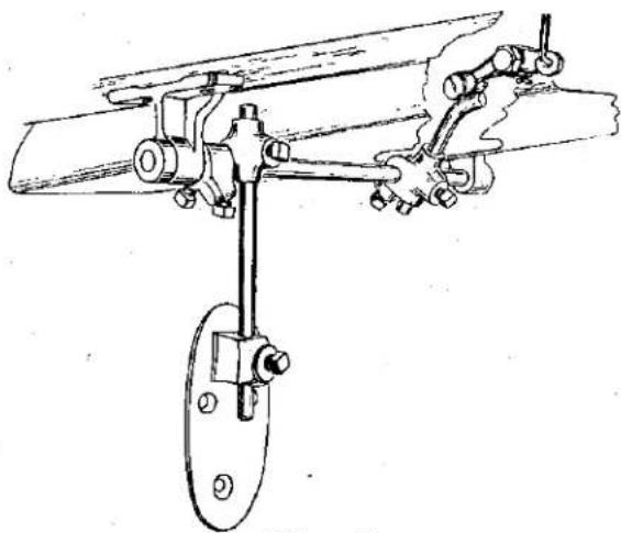
KNEE PRESS
The knee press is attached to Union Special table tops at the location designated by punch marks on the underside. For other boards, locate the knee press so that the center of the shaft is 8 1/4 inches from the right side of the cut-off. The knee press assembly should appear as in (Fig. 1).
DRIP PAN
The drip pan is attached to Union Special table tops at the indentation marks on the inside of the cut-out, using the nails furnished with the accessories. For other table tops, the drip pan should be set high enough to clear the knee press and low enough to clear the bottom of the machine. It should be laterally located so that it is directly under the base of the machine.
natural_image
Technical line drawing of a mechanical linkage assembly (no text or symbols)Fig. 1
BELTS
These machines are equipped to use either No. 1 "V" or round belt.
LUBRICATION
CAUTION!!
The oil has been drained from the main reservoir and the hook shaft gear case before shipment, and these reservoirs must be filled before starting to operate. Lubricate machine thoroughly in accordance with instructions and run slowly for several minutes to distribute the oil to the various parts. Full speed operation can then be expected without damage.
RECOMMENDED OILS
Use a straight mineral oil of a Saybolt viscosity of 90 to 125 seconds at 100° Fahrenheit in main reservoir and hook shaft gear case. This is equivalent to Union Special oil specification No. 175.
text_image
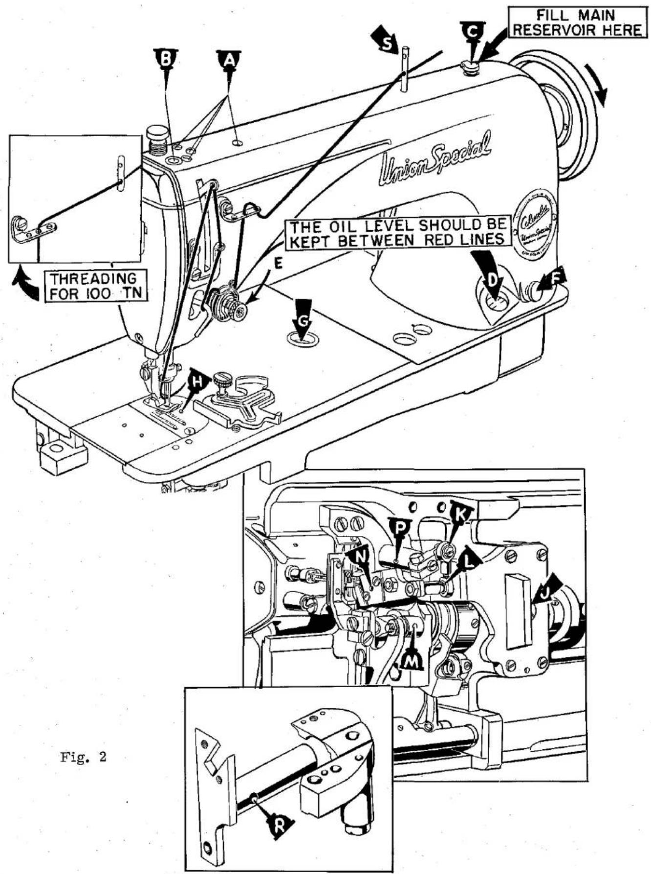
FILL MAIN RESERVOIR HERE Union Special THE OIL LEVEL SHOULD BE KEPT BETWEEN RED LINES THREADING FOR 100 TN Fig. 2LUBRICATION (Continued)
RECOMMENDED OILS (Continued)
Oils conforming to specification No. 175 may also be used in the manually oiled places.
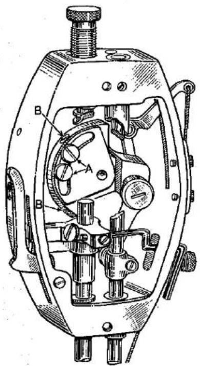
For trouble free operation, oil the machine as indicated in the diagram (Fig. 2).
With needle bar at the top of its stroke, oil the holes (A) twice daily. In oiling hole (B), very little oil should be used and only around the outer edges of the needle bar. Do not put oil into the hole in the needle bar, as it will flow out when machine is operated at high speed. A can of oil, No. 28604 R, is included with the accessories packed with the machine. It contains a sufficient quantity to fill both reservoirs. The main reservoir is filled through oil cup (C) and the supply is usually replenished about twice a month. However, the oil level should be checked from time to time and kept between the lines on the gauge (D).
The hook shaft gear case is filled at the plug screw hole (J). A quantity of oil sufficient to bring the level up to the plug screw hole, when the machine is tilted back against the rest pin, should be used. Remove plug screw and check the level of oil about every six months.
CAUTION!!
Do not use a compounded oil in the feeding drive shaft gear case or hook shaft gear case, as these oils separate and froth.

text_image
A B C D EFig. 3
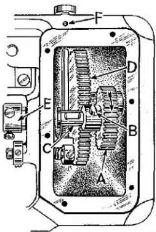
Lubrication of most of the mechanism below the bed plate is automatically accomplished through the feed driving shaft which is tubular. Oil is introduced into the shaft at the gear end by means of an oil distributing plate (A, Fig. 3) which is secured to the large gear case cover (B) by means of two screws (C) and retaining block (D).
Should it ever become necessary to remove any of the parts from the gear case, it is imperative that the adjustment of the oil distributing plate be checked very carefully. This can be done by removing the large plug screw at the right end of the gear housing and looking through the hole. The low point of the oil
distributing plate must be even with or slightly below the center of shaft (E) and just touching it. This is a very important adjustment as the functioning of the automatic lubrication of the lower part of the machine depends upon it.
The hook driving mechanism, below the bed plate, is manually lubricated, and the oiling places are indicated at (H, K, L, M, N, P, and R, Fig. 2). A few drops daily at these points will be sufficient.
NEEDLES
Use only genuine UNION SPECIAL needles.
The recommended needles for these machines are Type 29-C150 or 29 DEA, eye needle, (formerly System 150) and Type 29-C151, hook needle, (formerly System 151 SU). The minor number following the Type Symbol indicates the size.
NEEDLES (Continued)
These needles are available in the following sizes:
| NEW TYPE NO. | OLD SYSTEM NO. | DESCRIPTION | SIZE |
| 29 DEA-090/036 | 4/150 | Eye Needle | .038 |
| 29-C150-5 | 5/150 | Eye Needle | .042 |
| 29 DEA-110/044 | 6/150 | Eye Needle | .044 |
| 29 DEA-140/054 | 8/150 | Eye Needle | .054 |
| 29-C151-4 | 4/151 | Hook Needle | .038 |
| 29-C151-5 | 5/151 SU | Hook Needle | .042 |
| 29-C151-6 | 6/151 SU | Hook Needle | .046 |
| 29-C151-7 | 7/151 SU | Hook Needle | .050 |
| 29-C151-8 | 8/151 SU | Hook Needle | .054 |
| 29-C151-10 | 10/151 SU | Hook Needle | .062 |
Style 100 P is set with 29-C150-5 or 5/150 eye needle and 29-C151-5 or 5/151 SU hook needle and No. 60 cotton thread. Finer needles and cotton may be used on this machine. To use heavier threads such as 40-30 cotton or 2/3 rayon twist, it is necessary to change the needle spacer to C1021 P-073 and to use 29 DEA-110/044 or 6/150 eye needle and 29-C151-6 or 6/151 SU hook needle.
Style 100 S for sportswear is set with 29 DEA-110/044 or 6/150 eye needle and 29-C151-7 or 7/151 SU hook needles and C3 saddle stitch rayon twist. For trousers, use 29 DEA-110/044 or 6/150 eye needle and 29-C151-6 or 6/151 SU hook needle with No. 50 or size A cotton. Finer needles and thread may also be used.
Style 100 LS is set with 29 DEA-140/054 or 8/150 eye needle and 29-C151-10 or 10/151 SU hook needle with size E cotton thread. Finer needles and thread may be used.
Style 100 NTN is set with 29-C150-5 or 5/150 eye needle and 29-C151-5 or 5/151 SU hook needle with size 00 mercerized.
To have orders promptly and accurately filled, an empty container, a sample needle, or the type number should be forwarded.
OPERATOR'S INSTRUCTIONS
INSERTING THE NEEDLES
Insert the needles in the needle bar as far as they will go, with the spots or scarfs to the right, and with the eye needle in the rear hole and the hook needle in the front.
THREADING
Thread machine in accordance with threading diagram (Fig. 2).
The main diagram illustrates the threading for Styles 100 P, 100 S and 100 LS. The insert illustrates the difference between the threading of Style 100 NTN and the other styles.
Please note that on Style 100 NTN, when fine nylon (Z15 size) or fine cotton (2/0 size) threads are used, the threading of the check spring and take-up lever is omitted.
OPERATOR'S INSTRUCTIONS (Continued)
NEEDLE THREAD TENSION
The needle thread tension is varied by turning the tension regulating nut (E, Fig. 2). Turning the nut in a clockwise direction increases the tension and counterclockwise decreases the tension. This should not be done when the presser foot is in its raised position, and is generally done while the machine is sewing on a piece of scrap material.
LENGTH OF STITCH
The showing stitch remains the same, but the space between the stitches changes when setting for a longer or shorter stitch. The total length of stitch can be set from approximately 3 to 10 stitches per inch on Styles 100 P, 100 S, 100 LS, and from approximately 2 1/3 to 10 stitches per inch on Style 100 NTN. Most tie manufacturers, however, prefer the maximum stitch length.
TO CHANGE THE STITCH LENGTH
Press plunger (F, Fig. 2) in firmly. While holding plunger in, turn handwheel in operating direction until stitch regulating finger is felt to drop into the slot of feed eccentric. Continuing to hold the plunger in, turn handwheel in operating direction to increase the stitch length and in opposite direction to decrease the stitch length.
Comparative stitch lengths are indicated by the graduations on the dial (G) in bed plate, ranging from S (short) to L (long). Release the plunger.
The stitch regulating plunger may be locked at any setting by means of the locking screw located on the underside of the bed plate lip directly below the plunger.
text_image
AFig. 4
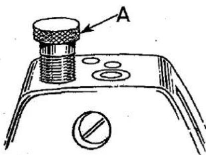
PRESSURE ON MATERIAL
The presser spring should exert only enough pressure to make the work feed uniformly. To increase the pressure on the presser foot, turn the presser spring regulator (A, Fig. 4) in clockwise direction. Turning the regulator counterclockwise decreases the pressure.
OPERATING STYLE 100 NTN
Raise the presser foot on the machine with the knee lifter. Then, draw the tie lining into the stretching device (A, Fig. 5) through the lining guide (B) and under
the presser foot, placing the edge of the lining against the ruler edge guide (C) with the end of the lining located at whichever number you choose to use as a starting point.
A tape slot (D) is provided in the plate, for the tape which is drawn in simultaneously with the tie lining. Its use is optional. Many operators work with the tie linings draped across their right knee. If this method is used, the lining should be inserted under the angular guide (F). If the operator prefers to let the tie linings hang straight down, the angular guide (F) should be removed.
The tie is now placed under the presser foot and against the adjustable tie gauge (E). Tie and lining are now sewn together the entire length.
OPERATOR'S INSTRUCTIONS (Continued)
OPERATING STYLE 100 NTN (Continued)
To remove the tie, be sure the needles are up and have just started their downward travel. Then, raise the presser foot with the knee lifter. With the left hand, draw the tie at least 1 inch to the rear to pull off thread. Then, break the thread by snapping the tie to the rear left.

text_image
Technical diagram of a sewing machine with labeled parts A through F, showing internal components and assembly lines.Fig. 5
The forward portion of the slot in the presser foot has a knife edge so that threads which will not break by the above method may be readily cut. When using nylon or heavier threads, proceed as outlined above, then, draw tie to the left, lowering the presser foot at the same time to sever threads.
The ruler edge guide (C) can be moved to the left or right to center the lining so that the stitching will be in the center of the lining. The marks on ruler edge guide (C) are used for locating the starting position on lining and tie.
The lining stretching device (A) has an adjustable tension. If the lining is puckering, more tension is required on the stretching device (A). Light weight linings require less tension than heavy weight linings. Linings must be cut on the bias. When the stitching is not centered on the tie lining, it may be necessary to move the lining stretching device (A) to the left or right of center line.
MECHANIC'S INSTRUCTIONS
SETTING THE NEEDLE BAR TO HEIGHT
The lower needle bar bushing, the one to which the needle bar is timed, is set at the factory. The distance from the bottom of the bushing to the throat plate seat is 2.298 (2 19/64) inches (Fig. 6).

text_image
A 22598Fig. 6
When the needle bar is in its lowest position, the upper timing line on the needle bar should be even with the lower edge of the needle bar bushing. To change the position of the needle bar, turn the handwheel in operating direction until the needle bar is in its lowest position, then, loosen the clamp screw (A) and move the bar to the proper timing line. Insert a pin in the 3/64 inch hole between the timing lines and turn the needle bar 3 to 5 degrees to left of the line of feed on 100 P and 100 NTN machines, 2 to 3 degrees on 100 S machine, and 1 degree on 100 LS machine.
FEED DOG HEIGHT
In regulating the height of the feed dog, it should be at its highest position and the presser foot resting directly against it. Feed dog should show the depth of a full tooth above the throat plate.
The feed dog holder attaching screw (A, Fig. 7) should be loosened slightly, and regulat-
ing screw (B) should be turned either clockwise to raise the feed dog, or counterclockwise to lower it. Make sure that the bottom of the shank of the feed dog holder rests against the head of the regulating screw.

text_image
Technical diagram of a mechanical device with labeled components A, B, C, and DFig. 7
The feed dog can be tilted up or down as required by loosening screws (A and C).
Loosen feed dog holding screws (D) to space the feed dog, front to back or sideways in throat plate.
text_image
C D 1/16 1/4 1/16 A BFig. 8
PRESSER FOOT HEIGHT
With the feed dog at the bottom of its stroke, set the presser foot height so that there is 1/4 inch space between the bottom of the presser foot and the top of the throat plate when the presser foot lifter lever is at its highest position.
To make this adjustment, loosen screw (D, Fig. 8), and with the hand lifter (B) in its up position, move the presser bar to secure the desired height of foot and re-tighten screw (D). When the above adjustment is made, care must be taken that the needles are centered in the presser foot needle slot.
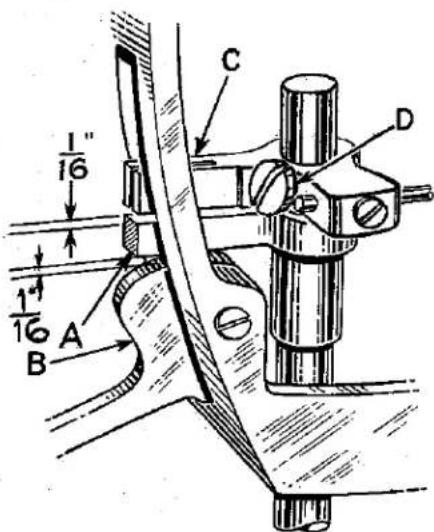
PRESSER BAR CONNECTION
The presser bar connection (A, Fig. 8) should be set so that it is 1/16 inch from the hand lifter (B) at all times.
MECHANIC'S INSTRUCTIONS (Continued)
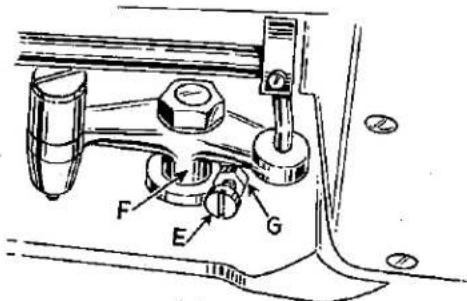
PRESSER BAR CONNECTION (Continued)
This is accomplished by turning the machine over on its side, loosening lock nut (G, Fig. 9) and relocating the stop screw (E) on the lifter lever bell crank (F). By turning the stop screw counterclockwise, the presser bar connection is brought closer to the hand lifter. Turn the stop screw to secure desired 1/16 inch space. Tighten lock nut (G) to lock screw in position.
PRESSER BAR GUIDE
When locating the presser bar guide (C, Fig. 8), the presser foot must rest directly against the throat plate with the feed dog in its lowest position.
The guide is properly set when there is a 1/16 inch space between presser bar guide and the connection.
text_image
Technical diagram of a mechanical assembly with labeled parts F, E, G and numbered annotationsFig. 9
To obtain this setting, loosen set screw(D) in the guide and insert screw driver between the connection
and the guide. Tap on presser foot to insure its being down on the throat plate, center the foot by turning it so that needle enters the middle of its slot and re-tighten screw (D) in guide.
THREAD CONTROL
text_image
C B E A DFig. 10
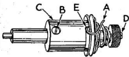
Test check spring tension (A, Fig. 10). There should be enough tension to insure a good returning snap when spring is depressed and released. Should it require adjusting, loosen set screw in the head on right side of tension post (G, Fig. 12) and remove tension post assembly. Partially loosen tension post set screw (B, Fig. 10) in tension post socket (C). Holding the socket in the left hand, turn the tension post (D) counterclockwise with the right hand until the check spring moves away from the upper stop (E) and has no tension on it. Turn the tension post (D) in a clockwise direction until the spring again touches the upper stop (E). Then, proceed further in the same direction until the desired tension is obtained. When correctly set, the tension post set screw (B) should be drawn up snugly, but not forcefully. Further adjustment of the check spring tension can be made by inserting a screw driver into the slotted end of the tension post (D) and turning in the required direction.
Replace tension assembly with the check spring about 3/8 inch above the thread take-up wire. While the tension post assembly is being replaced, the presser foot should be resting on the throat plate.
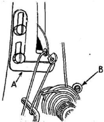
The frame take-up eyelet (A, Fig. 11) should be set at its highest position.
For the final setting of check spring, sew slowly on a piece of material and observe the action of the check spring. The spring should have completed its travel and rest against its stop as the needle bar reaches the bottom of its stroke.
text_image
Technical diagram showing mechanical linkage with labeled parts A and B, likely illustrating a linkage mechanism or assembly.Fig. 11
MECHANIC'S INSTRUCTIONS (Continued)
LOCATING TENSION RELEASE MECHANISM
The tension assembly should be located in bed from front to back, so that when the presser foot is raised to its highest position, the tension discs (F, Fig. 12) are
opened just enough to allow the thread to pass through the discs freely.

text_image
Technical diagram showing mechanical assembly with labeled parts H, G, J, and FFig. 12
To position the tension assembly, see that set screw in bed (G, Fig. 12) is loose and tension assembly adjusting screw (B, Fig. 11) is screwed down to the bed.
Lift the presser foot hand lifter to its highest position. With the left hand, grasp the thread and pull it through the tensions, with the right hand, push tension post deeper into the machine until release pin (H, Fig. 12) pressing against the presser bar connection (J) has opened the tension discs just enough to allow the thread to pull through freely.
Re-tighten set screw (G), turn tension assembly adjusting screw (B, Fig. 11) counterclockwise until it contacts the flange of the tension post socket.
SETTING THE HOOK ON THE CARRIER
Set the hook high on the carrier and tilt backwards as far as it will go. Use screws (A, Fig. 13) to make this adjustment. Care must be taken that the hook point does not contact the bottom of the plunger after making this adjustment.
TIMING THE HOOK
Turn handwheel in operating direction until the needle bar has started to rise from its lowest position and the

text_image
Technical diagram of a mechanical assembly with labeled parts A and BFig. 14
timing line (A, Fig. 14) at bottom of 3/64 inch hole is even with the bottom of the lower needle bar bushing. At this time, the point of the sewing hook (B) should be even with the centerline of the eye needle on the 100 P and 100 NTN machines, centered between the eye needle and the hook needle on the 100 S machine and 1/16 inch past the eye needle in its direction of travel on the 100 LS machine. The above adjustment may be made by loosening the three screws (E, Fig. 16) in the hook driving barrel and rotating the barrel until the above condition is satisfied.
Set the hook point as close as possible to the eye needle without contacting it on the 100 P, 100 S, 100 NTN machines. - The 100 LS machine will require a .003 to .005 inch space between the sewing hook point and the scarf of the eye needle.

text_image
A BFig. 13
MECHANIC'S INSTRUCTIONS (Continued)
TIMING THE HOOK (Continued)
This is done by loosening the Allen screw located in the lower bracket. Move the sewing hook shaft bushing (D, Fig. 16) either to the left or right to locate the sewing hook properly. Re-tighten the Allen screw.
TIMING THE PLUNGER
The plunger should pass midway between both needles on Styles 100 P and 100 NTN. On Style 100 S, the plunger should be .010 inch from the hook needle. On Style 100 LS, the plunger should be .005 inch from the hook needle. Loosen the plunger block holder screw (B, Fig. 13) and move the block in the required direction to make this adjustment.
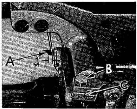
Set the plunger so that the vertical portion (A, Fig. 15) extends 3/64 inch beyond the left side of needles at its farthest point of travel to the left.
This adjustment is made by loosening clamp screw (B) and turning slotted shaft (C) in the required direction.
text_image
A 3" 64 B CFig. 15
STITCH FORMATION
Place cloth under foot and thread machine. Lay machine on its side and turn handwheel in operating direction and observe how the thread is carried between the needles into the hook needle by the plunger. As the thread is released by the sewing hook and plunger, it is drawn up by the take-up, and the feed motion completes the stitch. Any burr or sharp groove on the plunger or sewing hook must be removed. To turn cloth at desired corner or point, lower hook needle until the point is 1/16 inch above cloth. Raise presser foot and make turn.

text_image
C E D A BFig. 16
HOOK CARRIER BRACKET
Should it become necessary to replace either the hook carrier bracket (A, Fig. 16) or the shim gasket (B) for it, it is extremely important that the proper distance between the hook barrel (C) and hook carrier bushing (D) be maintained. Use a micrometer to check this dimension as shown at "X" in Fig. 16. On Styles 100 P, 100 S, and 100 NTN, this dimension is 1.375 inch plus .005 inch and on Style 100 LS, it is 1.400 inch plus .005 inch.
In order to achieve this adjustment, it will be necessary to select shim gaskets of the proper thickness to use between the hook carrier bracket (A) and the bed casting.
On Styles 100 P, 100 S, and 100 NTN, at least one shim gasket must be used, and on Style 100 LS, at least one gasket on each side of the spacing plate must be used to prevent oil leakage.
Refer to parts list in back of book for shim gasket part numbers and thicknesses.
MECHANIC'S INSTRUCTIONS (Continued)
FEED TIMING
This timing is the relationship which exists between the feed dog and the needle bar motions.
Set the stitch regulator for the longest stitch. Set the feed dog to show the depth of a full tooth above the throat plate. Turn handwheel in operating direction until the bottom of the descending needle eye is even with the top surface of the throat plate. When the needle bar is in this position, the top of the feed dog teeth should be even with the top surface of the throat plate. A simple method of advancing or retarding the feed timing is provided in the head of the machine. Loosen the two screws holding the counterweight to the segment plate (A, Fig. 17) and the two screws (B) holding the counterweight to the main shaft. Hold the handwheel and turn the counterweight in a clockwise direction to retard the feed, and in a counterclockwise direction to advance the feed. Be sure to re-tighten all four screws securely, making certain that the counterweight does not slip. Any time the feed timing is changed, it is necessary to retime the hook.
text_image
Technical diagram of a mechanical device with labeled parts A and B, showing internal components and connections.Fig. 17
MACHINE TIMING
If at any time the machine is disassembled, the machine will have to be retimed as follows:
- Lay machine on its side on the bench.
- Remove the large gear housing cover. Note: Caution should be observed that machine is tilted far enough back so oil will not leak out. Also, be careful in removing the housing cover that the gasket is not mutilated.
- Loosen screws (B, Fig. 18) and slide gear (A) to the extreme right so it is out of mesh with the idler gear (D).
- Looking through the stitch length indicator window on the top of the bed plate, rotate the lower main
shaft (C) in the operating direction until the timing mark "T" appears between the pointers of the indicator window. Then, rotate upper main shaft in the operating direction until the needle bar reaches its highest position and descends 1/64 inch on Styles 100 P, 100 S, and 100 NTN and 1/16 inch on Style 100 LS. Carefully turn gear (A) without disturbing the lower main shaft setting until the set screw lies directly above the flat in the lower main shaft. The gears should then be engaged as closely as possible in this position. While holding the gear and thrust collar (E) tightly between thumb and forefinger, tighten set screw against flat in shaft securely, then, tighten the second set screw and check to see that there is no play in the shaft, and that the machine revolves freely.
- Clean, dry and re-seal gasket and housing cover using gasket cement.
- Replace housing cover. Check position of oil distributing plate as previously described under "Lubrication".
- Re-set hook.
text_image
Technical diagram of a mechanical device with labeled components A through E and FFig. 18
USEFUL SUGGESTIONS
If the machine fails to work satisfactorily, though apparently in good repair, it is possible that some minor trouble exists. For this reason, delay may be avoided by acting on the following:
- See that the needles are set properly; that they are the recommended needles; that they are straight and free from nicks and rough places; that they are inserted in the needle bar as far up as they will go; and that there is clearance all around needles as they enter the throat plate.
- See that the machine is threaded correctly and the needle thread is delivered to the machine properly.
- See that the proper tension is applied to the thread.
- See that the presser foot is set so that the needle does not strike it.
- See that the feed dog is not striking the hook or throat plate.
- Take off throat plate and remove accumulated lint from feed dog slots and hook.
- See that there are no nicks or cuts in the wall of the throat plate needle hole. String out this hole with fine emery cord or cloth.
- See that the take-up spring acts freely, is not grooved or nicked. Remove any gummy oil and dirt around tension discs.
- See that the point of the hook is not blunted, broken or nicked.
- See that the hook is timed correctly.
- See that the feed is timed correctly.
- See that the plunger is set correctly.
- See that all screws are tight.
ORDERING REPAIR PARTS
ILLUSTRATIONS
This catalog has been so arranged as to simplify the ordering of repair parts. Exploded views of the various sections of the mechanism are shown so that the parts may be seen in their actual position in the machine. On the page opposite the illustration will be found the listing of the parts with their part numbers, descriptions and the number of pieces required in the particular view being shown.
The numbers in the first column are reference numbers only and indicate the position of the part in the illustration. The reference number should never be used in ordering parts. Always use the part number shown in the second column.
Those component parts of sub-assemblies which can be furnished for repairs are indicated by the fact that their descriptions are indented under the descriptions of the main sub-assembly. Example:
| 45 | 61149 | Stitch Length Indicator | 1 |
| 46 | 95 | Set Screw | 1 |
| 47 | 96 | Time Spot Screw | 1 |
In those cases where the parts for the various styles in Class 100 are not the same, the difference will be shown in the illustrations and descriptions. When a part is used in all machines covered by this catalog, no machine style will be mentioned.
At the back of the book will be found a numerical index of all the parts shown in this book, which will facilitate locating the illustration when only the part number is known.

text_image
Union Special 36 35 34 33 32 31 30 29 28 27 26 25 24 23 22 21 20 19 18 17 16 15 14 13 12 11 10 9 8 7 6 5 4 3 2 1 3 2 4 5 6 7 8 9 10 11 12 13 14 15 16 17 18 19 20 21 22 23 24 25 26 27 28 29 30 31 32 33 34 35 36 37 38 39 40 41 42 43 44 45 46 47 48 49 50 51 52 53 54 55ORDERING REPAIR PARTS (Continued)
IDENTIFYING PARTS
Where the construction permits, each part is stamped with its part number. Some of the smaller parts are stamped with an identification letter to distinguish them from parts similar in appearance.
All part numbers represent the same part, regardless of the catalog in which they appear.
USE GENUINE NEEDLES AND REPAIR PARTS
Success in the operation of these machines can be secured only by the use of genuine UNION SPECIAL Needles and Repair Parts as furnished by the Union Special Corporation, its subsidiaries and authorized distributors. They are designed according to the most approved scientific principles, and are made with the utmost precision. The maximum efficiency and durability are assured.
Genuine repair parts are stamped with the Union Special trademark, U. S. Emblem. Each trademark is your guarantee of the highest quality in materials and workmanship.
TERMS
Prices are strictly net cash and subject to change without notice. All shipments are forwarded at the buyer's risk f.o.b. shipping point. Parcel Post shipments are insured unless otherwise directed. A charge is made to cover the postage and insurance.
MAIN FRAME, MISCELLANEOUS BUSHING, COVERS AND PLATES
| Ref. No. | Part No. | Description | Amt. Req. |
| 1 | B61382 H | Head Cover | 1 |
| 2 | 22569 B | Screw | 2 |
| 3 | 61293 | Oil Tube | 2 |
| 4 | 666-126 | Oil Wick | 1 |
| 5 | 61393 C | Oil Tube | 1 |
| 6 | 666-127 | Oil Wick | 1 |
| 7 | 666-20 | Oil Wick | 2 |
| 8 | 61393 B | Oil Tube | 1 |
| 9 | 61272 | Needle Thread Guide Pin | 1 |
| 10 | 61394 AE | Oil Cup | 1 |
| 11 | 666-104 | Oil Wick | 1 |
| 12 | 61490 | Main Shaft Bushing, right | 1 |
| 13 | 50-558 Blk. | Plug | 1 |
| 14 | 22539 D | Plug Screw | 1 |
| 15 | 61245 G | Stitch Regulator Thumb Screw Locking Insert | 1 |
| 16 | 22597 A | Screw | 1 |
| 17 | 50-568 Blk. | Oil Sight Gauge | 1 |
| 18 | 61432 B | Feed Driving Shaft Bushing, right | 1 |
| 19 | 22597 A | Screw | 1 |
| 20 | 61449 H | Stitch Regulator Indicator Window | 1 |
| 21 | 22863 B | Tension Assembly Adjusting Screw | 1 |
| 22 | 22585 A | Screw | 2 |
| 23 | C2028 | Thread Eyelet | 1 |
| 24 | 61432 D | Feed Driving Shaft Oil Retaining Bushing, right | 1 |
| 25 | 61341 D | Hook Shaft Bushing, right | 1 |
| 26 | 61432 E | Feed Driving Shaft Oil Retaining Bushing, left | 1 |
| 27 | 95 | Screw | 1 |
| 28 | 61341 C | Hook Shaft Bushing, left | 1 |
| 29 | 61432 C | Feed Driving Shaft Bushing, left | 1 |
| 30 | 61293 N | Plug, for inside of arm | 2 |
| 31 | 61490 A | Main Shaft Bushing, left | 1 |
| 32 | 22570 A | Screw | 1 |
| 33 | 61271 | Thread Eyelet | 1 |
| 34 | 61454 | Needle Bar Bushing, lower | 1 |
| 35 | 61457 C | Presser Bar Bushing, lower | 1 |
| 36 | 61470 F | Needle Bar Bushing Thread Guide, for Style 100 LS | 1 |
| 37 | 61402 | Bed Slide | 1 |
| 38 | 61273 | Bed Slide Spring | 1 |
| 39 | 91 A | Screw | 2 |
| 40 | C1017 P | Throat Plate, for Style 100 P | 1 |
| C1017 S | Throat Plate, for Style 100 S | 1 | |
| 41 | 18-983 | Screw | 1 |
| 42 | C1018 | Thread Retainer | 1 |
| 43 | 376 | Screw | 2 |
| 44 | C1017 NTN | Throat Plate, for Styles 100 TN, 100 NTN | 1 |
| 45 | C1017 LS | Throat Plate, for Style 100 LS | 1 |
| 46 | 61492 A | Tension Post Socket | 1 |
| 47 | 89 | Set Screw | 1 |
| 48 | 22597 E | Set Screw | 1 |
| 49 | 61492 | Tension Post | 1 |
| 50 | 61292 G | Tension Release Pin | 1 |
| 51 | 61453 | Take-up Spring | 1 |
| 52 | 109 | Tension Disc | 2 |
| 53 | 61292 H | Tension Release Washer | 1 |
| 54 | 61392 F-9 | Tension Spring | 1 |
| 55 | 61292 C | Tension Nut | 1 |
| 56 | 22570 A | Screw | 8 |
| 57 | 61382 J | Cover, for feed driving shaft gear case | 1 |
| 58 | 61282 D | Gasket | 1 |
| 59 | 61394 R | Gasket | 1 |
| 60 | 61394 Q | Oil Distributing Plate Retaining Block | 1 |
| 61 | 61394 P | Oil Distributing Plate | 1 |
text_image
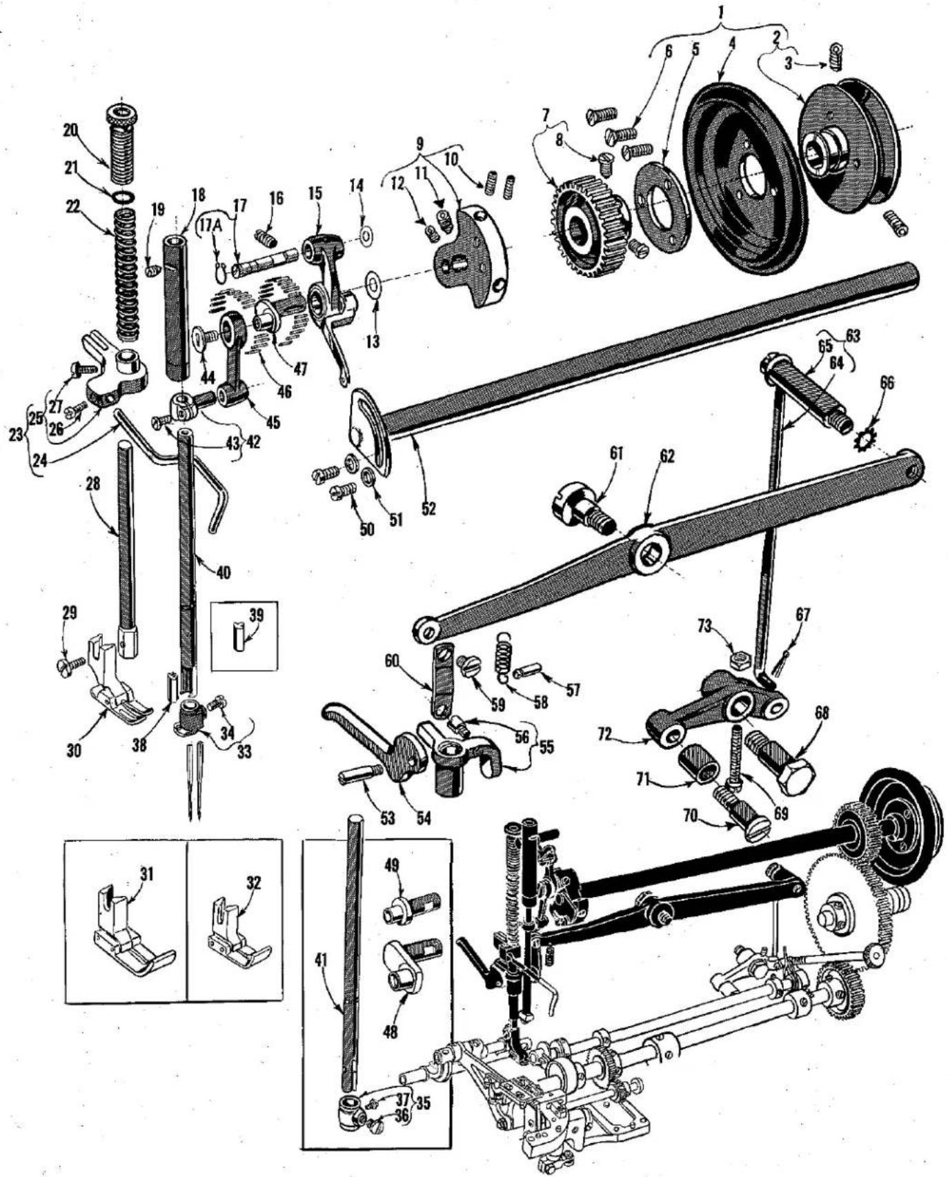
Technical diagram of a mechanical assembly with numbered parts and exploded views, likely from an engineering manual.UPPER SHAFT, PRESSER BAR, NEEDLE BAR, AND FOOT LIFTER MECHANISM
| Ref. No. | Part No. | Description | Amt. Req. |
| 1 | 61421 | Handwheel Assembly, for No. 1 "V" or Round Belt | 1 |
| 2 | 61421 A | Pulley Hub | 1 |
| 3 | 22894 AB | Screw | 2 |
| 4 | 61321 J | Handwheel | 1 |
| 5 | 61321 L | Hub Washer | 1 |
| 6 | 22574 | Screw | 3 |
| 7 | 61360 | Main Shaft Driving Gear | 1 |
| 8 | 22884 | Screw | 2 |
| 9 | 61391 C | Main Shaft Counterweight | 1 |
| 10 | 22894 V | Screw | 2 |
| 11 | 22894 U | Spot Screw for Styles 100 P, 100 S | 1 |
| 22596 F | Set Screw for Styles 100 LS, 100 NTN | 1 | |
| 12 | 22894 W | Set Screw | 1 |
| 13 | 61351 C | Thrust Washer | 1 |
| 14 | 61451 C | Thrust Washer | 1 |
| 15 | 61351 Q | Take-up Lever Assembly for Styles 100 P, 100 S, 100 NTN | 1 |
| 61451 H | Take-up Lever Assembly for Style 100 LS | 1 | |
| 16 | 22597 A | Screw | 1 |
| 17 | 61251 D | Take-Up Lever Pin | 1 |
| 17A | 660-205 | Retaining Ring | 1 |
| 18 | 61454 D | Needle Bar Bushing, upper | 1 |
| 19 | 96 | Screw | 1 |
| 20 | 61457 B | Presser Spring Regulator | 1 |
| 21 | 61256 G | Washer | 1 |
| 22 | 61256 | Presser Spring | 1 |
| 23 | 29475 AB | Take-up Thread Wire Assembly | 1 |
| 24 | 61453 B | Take-up Spring Thread Wire | 1 |
| 25 | 61459 A | Presser Bar Guide | 1 |
| 26 | 77 | Screw | 1 |
| 27 | 93 A | Screw | 1 |
| 28 | 61457 | Presser Bar | 1 |
| 29 | 22775 | Screw | 1 |
| 30 | C1015 P | Presser Foot for Style 100 P | 1 |
| C1015 S | Presser Foot for Style 100 S | 1 | |
| 31 | C1015 LS | Presser Foot for Style 100 LS | 1 |
| 32 | C1015 NTN | Presser Foot for Style 100 NTN | 1 |
| 33 | C1022 | Needle Clamp for Styles 100 P, 100 S, 100 NTN | 1 |
| 34 | 22562 | Set Screw | 1 |
| 35 | C1022 LS | Needle Clamp for Style 100 LS | 1 |
| 36 | 18-623 | Set Screw | 1 |
| 37 | 18-621 | Set Screw | 1 |
| 38 | C1021 P-062 | Needle Spacer for Style 100 P | 1 |
| C1021 P-073 | Needle Spacer for Style 100 NTN | 1 | |
| 39 | C1021 S | Needle Spacer for Style 100 S | 1 |
| 40 | C1020 | Needle Bar for Styles 100 P, 100 S, 100 NTN | 1 |
| 41 | C1020 LS | Needle Bar for Style 100 LS | 1 |
| 42 | 61255 | Needle Bar Connection | 1 |
| 43 | 22562 B | Screw | 1 |
| 44 | 22757 C | Screw | 1 |
| 45 | 61255 H | Needle Bar Link for Styles 100 P, 100 S, 100 NTN | 1 |
| 61455 C | Needle Bar Link for Style 100 LS | 1 | |
| 46 | 61351 K-625 | Needle Bearings, .0625 inch diameter | 38 |
| 61351 K-626 | Needle Bearings, .0626 inch diameter | 38 | |
| 61351 K-627 | Needle Bearings, .0627 inch diameter | 38 | |
| 47 | 61452 A | Crank Pin for Styles 100 P, 100 S | 1 |
| 48 | C1036 LS | Crank Pin for Style 100 LS | 1 |
| 49 | C1036 NTN | Crank Pin for Style 100 NTN | 1 |
| 50 | 22596 D | Screw | 2 |
| 51 | 8372 A | Washer | 2 |
| 52 | 61322 B | Main Shaft | 1 |
| 53 | 22789 M | Screw Pin | 1 |
| 54 | 61265 | Hand Lifter | 1 |
| 55 | 61458 | Presser Bar Connection | 1 |
| 56 | 22892 | Screw | 1 |
| 57 | 61267 G | Spring Pin | 1 |
| 58 | 15872 F | Spring | 1 |
| 59 | 22758 B | Screw | 1 |
| 60 | 61267 | Lifter Lever Link | 1 |
| 61 | 22890 | Screw, left thread | 1 |
| 62 | 61466 A | Lifter Lever | 1 |
| 63 | 61368 A | Lifter Lever Extension Stud and Connecting Rod, complete | 1 |
| 64 | 61368 | Lifter Lever Connecting Rod | 1 |
| 65 | 61366 C | Lifter Lever Extension Stud | 1 |
| 66 | 652 B-20 | Lock Washer | 1 |
| 67 | 660-142 | Cotter Pin | 1 |
| 68 | 22817 A | Stud | 1 |
| 69 | 22874 F | Screw | 1 |
| 70 | 22712 F | Screw | 1 |
| 71 | 61368 F | Roller | 1 |
| 72 | 61468 | Lifter Lever Bell Crank | 1 |
| 73 | 9937 | Nut | 1 |
text_image
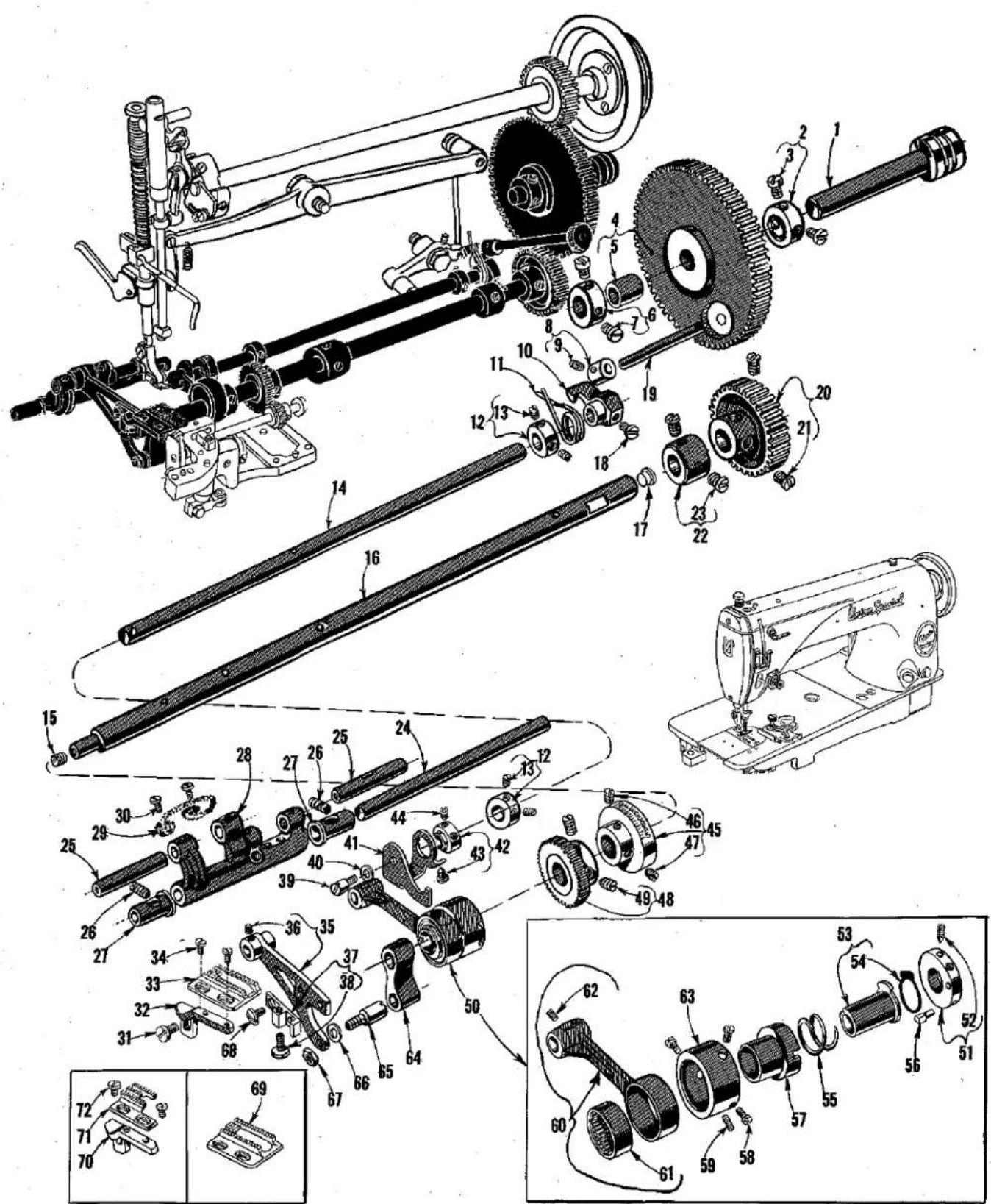
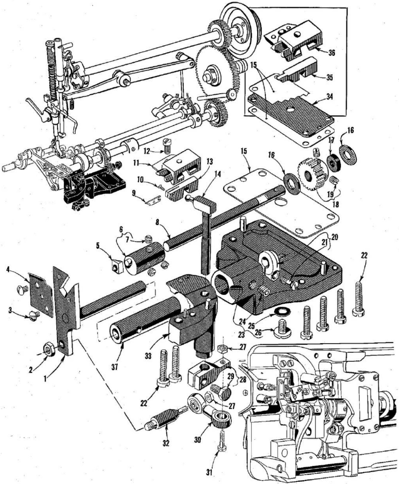
Technical diagram of mechanical assembly with numbered components and exploded views, including gears, linkages, and a sewing machine.FEED DRIVING AND STITCH REGULATING MECHANISM
| Ref.No. | PartNo. | Description | Amt.Req. |
| 1 | 62262 | Intermediate Gear Shaft | 1 |
| 2 | 61264 | Intermediate Gear Shaft Collar, right | 1 |
| 3 | HA61 D | Screw | 2 |
| 4 | 61261 A | Feed Driving Intermediate Gear | 1 |
| 5 | 61263 | Bushing | 1 |
| 6 | 61264 A | Intermediate Gear Shaft Collar, left | 1 |
| 7 | HA61 D | Screw | 2 |
| 8 | 161 | Collar | 1 |
| 9 | 88 | Screw | 1 |
| 10 | 61246 A | Stitch Regulator Plunger Lever | 1 |
| 11 | 61447 | Stitch Regulator Plunger Spring | 1 |
| 12 | 61248 H | Stitch Regulator Shaft Collar | 2 |
| 13 | 531 | Screw | 2 |
| 14 | 61348 A | Stitch Regulator Shaft | 1 |
| 15 | 22743 | Plug Screw | 1 |
| 16 | 61132 D | Feed Driving Shaft, for Styles 100 P, 100 S | 1 |
| 61432 K | Feed Driving Shaft, for Styles 100 LS, 100 TN, 100 NTN | 1 | |
| 17 | 50-552 Blk. | Plug | 1 |
| 18 | 93 A | Screw | 1 |
| 19 | 61445 | Stitch Regulator Plunger | 1 |
| 20 | 61260 A | Feed Driving Shaft Gear | 1 |
| 21 | 22884 | Screw | 2 |
| 22 | 61360 G | Feed Driving Shaft Collar | 1 |
| 23 | 22884 | Screw | 2 |
| 24 | 61236 G | Feed Rocker Shaft | 1 |
| 25 | 63435 A | Feed Bar and Feed Rocker Connection Link Shaft | 2 |
| 26 | 22894 E | Screw | 2 |
| 27 | 61336 U | Bushing | 2 |
| 28 | 61236 | Feed Rocker | 1 |
| 29 | 61336 Y | Feed Rocker Oil Wick | 1 |
| 30 | 90 | Screw | 2 |
| 31 | 22528 | Screw | 1 |
| 32 | 63439 A | Feed Dog Holder for Styles 100 P, 100 S, 100 LS | 1 |
| 33 | C1016 P | Feed Dog for Styles 100 P, 100 S | 1 |
| 34 | 22768 | Screw | 2 |
| 35 | 63434 C | Feed Bar | 1 |
| 36 | 89 | Screw | 1 |
| 37 | 63439 AL | Feed Dog Holder Support | 1 |
| 38 | 22775 A | Screw | 1 |
| 39 | 22802 A | Screw | 1 |
| 40 | 51242 M | Washer | 1 |
| 41 | 61449 F | Stitch Regulating Pawl | 1 |
| 42 | 61449 E | Stitch Regulating Pawl Collar | 1 |
| 43 | 22860 | Screw | 1 |
| 44 | 22845 G | Screw | 1 |
| 45 | 61149 | Stitch Length Indicator | 1 |
| 46 | 95 | Set Screw | 1 |
| 47 | 96 | Time Spot Screw | 1 |
| 48 | 61443 | Hook Shaft Driving Gear | 1 |
| 49 | 22894 J | Set Screw | 2 |
| 50 | 29126 DU | Feed Drive Eccentric Assembly, for Styles 100 P, 100 S, marked "DU" | 1 |
| 29126 DT | Feed Drive Eccentric Assembly, for Style 100 LS, marked "DT" | 1 | |
| 29126 DS | Feed Drive Eccentric Assembly, for Styles 100 TN, 100 NTN, marked "DS" | 1 | |
| 51 | 61437 A | Feed Driving Eccentric Timing Collar | 1 |
| 52 | 22764 B | Time Spot Screw, for Styles 100 P, 100 S | 1 |
| 719 | Time Set Screw, for Styles 100 LS, 100 TN, 100 NTN | 1 | |
| 53 | 61149 G | Stitch Regulating Eccentric, for Styles 100 P, 100 S | 1 |
| 61449 AB | Stitch Regulating Eccentric, for Styles 100 LS, 100 TN, 100 NTN | 1 | |
| 54 | 61149 H | Stitch Regulating Eccentric Friction Disc | 1 |
| 55 | 61449 B | Stitch Regulating Thrust Spring | 1 |
| 56 | 61437 B | Feed Driving Eccentric Pivot Pin, for Styles 100 P, 100 S | 1 |
| 61437 U | Feed Driving Eccentric Pivot Pin, for Styles 100 LS, 100 TN, 100 NTN | 1 | |
| 57 | 61137 | Feed Driving Eccentric, on Styles 100 P, 100 S | 1 |
| 58 | 22564 B | Screw | 3 |
| 59 | 719 | Screw | 1 or 2 |
| 60 | 61438 C | Connecting Rod | 1 |
| 61 | 660-226 | Needle Bearing | 1 |
| 62 | 88 | Screw | 1 |
| 63 | 61437 C | Feed Driving Eccentric Retaining Housing | 1 |
| 64 | 61233 N | Feed Link | 1 |
| 65 | 22845 D | Feed Link Stud | 1 |
| 66 | 61434 G | Washer | 1 |
| 67 | 15037 A | Nut | 1 |
| 68 | 88 D | Screw | 1 |
| 69 | C1016 LS | Feed Dog, for Style 100 LS | 1 |
| 70 | -61439 AW | Feed Dog Holder, for Styles 100 TN, 100 NTN | 1 |
| 71 | C1016 NTN | Feed Dog, for Styles 100 TN, 100 NTN | 1 |
| 72 | 22768 | Screw | 2 |
text_image
Technical diagram of a mechanical assembly with numbered components for identificationHOOK, PLUNGER, AND DRIVING MECHANISM
| Ref.No. | PartNo. | Description | Amt.Req. |
| 1 | C1033 P | Hook Carrier for Styles 100 P, 100 NTN---- | 1 |
| C1033 S | Hook Carrier for Style 100 S, 100 LS---- | 1 | |
| 2 | 1160 L | Nut---- | 1 |
| 3 | C717 | Screw---- | 2 |
| 4 | C1008 P | Looper Hook---- | 1 |
| 5 | C1032 | Slide Block---- | 1 |
| 6 | C1030 | Hook Shaft Barrel for Styles 100 P, 100 S,100 NTN---- | 1 |
| C1030 LS | Hook Shaft Barrel for Style 100 LS---- | 1 | |
| 7 | 18-634 | Set Screw---- | 3 |
| 8 | 61440 A | Hook Shaft---- | 1 |
| 9 | C1023 | Plunger for Styles 100 P, 100 S, 100 NTN---- | 1 |
| 10 | 18-134 | Screw for Styles 100 P, 100 S, 100 NTN---- | 1 |
| 11 | C1019 | Plunger Block for Styles 100 P, 100 S, 100 NTN---- | 1 |
| 12 | 22562 A | Screw---- | 1 |
| 13 | C1024 P | Plunger Slide for Styles 100 P, 100 NTN---- | 1 |
| C1024 S | Plunger Slide for Style 100 S---- | 1 | |
| 14 | C1025 | Plunger Ball Crank---- | 1 |
| 15 | 61482 R-3 | Shim Gasket, .003 inch thick (as required)---- | |
| 61482 R-10 | Shim Gasket, .010 inch thick (as required)---- | ||
| 16 | 61341 J | Thrust Washer---- | 2 |
| 17 | 61341 G | Oil Seal Washer---- | 1 |
| 18 | 61244 | Hook Shaft Pinion---- | 1 |
| 19 | 89 | Set Screw---- | 2 |
| 20 | 439-C116 R | Collar---- | 1 |
| 21 | 22562 A | Screw---- | 1 |
| 22 | 22874 | Screw---- | 6 |
| 23 | C1002 P | Hook Bracket---- | 1 |
| 24 | 22650 AD-4 | Set Screw---- | 1 |
| 25 | 660-257 | Gasket---- | 1 |
| 26 | 18-C87 | Screw---- | 1 |
| 27 | 1311 L | Nut---- | 2 |
| 28 | C1029 LS | Plunger Crank---- | 1 |
| 29 | 18-715 | Clamp Screw---- | 1 |
| 30 | C1034 | Ball Joint---- | 1 |
| 31 | 916 L | Screw---- | 1 |
| 32 | C1035 | Connection Stud---- | 1 |
| 33 | C1027 | Plunger Bracket---- | 1 |
| 34 | C1069 | Gasket for Style 100 LS---- | 1 |
| 35 | C1024 LS | Plunger Slide for Style 100 LS---- | 1 |
| 36 | C1019 LS | Plunger Block for Style 100 LS---- | 1 |
| 37 | C1000-1 | Hook Carrier Shaft Bushing---- | 1 |

text_image
Technical diagram of a mechanical assembly with numbered parts and exploded views, likely from an engineering or patenting context.ATTACHMENTS
| Ref.No. | PartNo. | Description | Amt.Req. |
| 1 | C1078 A | Tie Centralizer Plate, complete, for Styles 100 TN, 100 NTN | 1 |
| 2 | C1073 | Adjusting Plate, left | 1 |
| 3 | 22585 | Mounting Screw | 4 |
| 4 | C1077 A | Centralizer and Plate Assembly | 1 |
| 5 | C1049 A | Reference Plate and Bracket Assembly | 1 |
| 6 | 22551 B | Knurled Thumbscrew | 1 |
| 7 | 15489 B | Knurled Thumbscrew | 1 |
| 8 | C1059 | Edge Guide | 1 |
| 9 | 22513 | Screw | 2 |
| 10 | C1074 | Adjusting Plate, right | 1 |
| 11 | C1054 | Washer | 2 |
| 12 | C1053 | Tape Bar | 1 |
| 13 | 87 A | Screw | 3 |
| 14 | C1039 A | Machine Base, complete, for Styles 100 TN, 100 NTN | 1 |
| 15 | 650 AD-6 | Screw | 2 |
| 16 | 651 H | Nut | 2 |
| 17 | C1042 | Hinge Pin Collar | 1 |
| 18 | 39132 G | Hinge Pin | 2 |
| 19 | 61476 | Felt Pad | 4 |
| 20 | C1076 A | Lining Stretcher Gauge, complete, for Styles 100 TN, 100 NTN | 1 |
| 21 | C1066 | Lining Guide | 1 |
| 22 | 40-38 | Washer | 1 |
| 23 | 650 AD-5 | Screw | 1 |
| 24 | C1061 | Back Plate | 1 |
| 25 | C1075 | Bottom Lining Pad | 1 |
| 26 | C1072 | Spring | 1 |
| 27 | C1071 | Spring | 1 |
| 28 | 20-C616 | Nut | 1 |
| 29 | 650 AD-5 | Screw | 2 |
| 30 | 40-38 | Washer | 4 |
| 31 | 22-C214-2 | Pin | 3 |
| 32 | 68-C614 | Screw | 1 |
| 33 | G26 | Screw, for Styles 100 P, 100 S, 100 LS | 1 |
| 34 | 61403 B | Edge Guide, for Styles 100 P, 100 S, 100 LS | 1 |
text_image
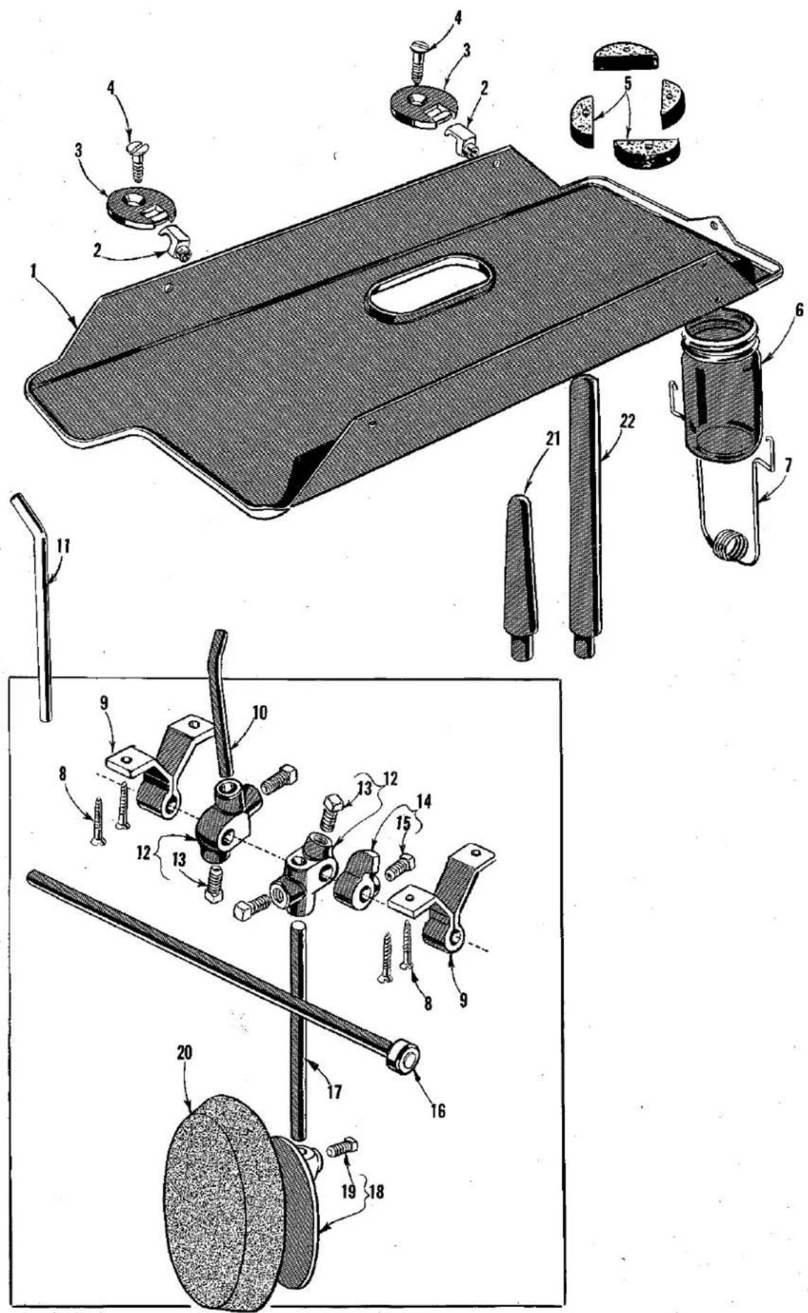
Technical diagram of a mechanical assembly with numbered parts and exploded views, likely for assembly or maintenance purposes.INSTALLATION ACCESSORIES
| Ref.No. | PartNo. | Description | Amt.Req. |
| 1 | 21393 E | Drip Pan---- | 1 |
| 2 | 61175 | Hinge Stud---- | 2 |
| 3 | 61374 | Hinge Plate for Styles 100 P, 100 S, 100 LS---- | 2 |
| 4 | 22846 Q-16 | Flat Head Wood Screws for Styles 100 P, 100 S,100 LS---- | 2 |
| 5 | 61376 G | Felt Pad for Styles 100 P, 100 S, 100 LS---- | 4 |
| 6 | 666-166 | Oil Drain Jar, glass---- | 1 |
| 7 | 21393 F | Oil Drain Jar Clamp Spring---- | 1 |
| 8 | SC329 A | Wood Screws, for knee lifter hanger---- | 4 |
| 9 | 21662 C | Knee Lifter Hanger---- | 2 |
| 10 | 21665 C | Knee Lifter Rock Shaft Connection Arm forStyles 100 P, 100 S, 100 LS---- | 1 |
| 11 | C1038 | Knee Lifter Rock Shaft Connection Arm forStyle 100 NTN---- | 1 |
| 12 | 21665 | Knee Lifter Rock Shaft Connection---- | 2 |
| 13 | 69 FD | Screw---- | 2 |
| 14 | 21661 D | Knee Lifter Rock Shaft Stop---- | 1 |
| 15 | 69 FD | Screw---- | 1 |
| 16 | 21661 P | Knee Lifter Rock Shaft---- | 1 |
| 17 | 21663 C | Knee Lifter Plate Rod---- | 1 |
| 18 | 21664 | Knee Lifter Plate---- | 1 |
| 19 | 69 FD | Screw---- | 1 |
| 20 | 660-168 | Knee Pad, rubber---- | 1 |
| 21 | 61378 | Machine Rest Pin for Styles 100 P, 100 S, 100 LS---- | 1 |
| 22 | 61378 A | Machine Rest Pin for Style 100 NTN---- | 1 |
NUMERICAL INDEX OF PARTS
| Part No. | Page No. | Part No. | Page No. | Part No. | Page No. | Part No. | Page No. |
| 18-C87 | 25 | C1024 P | 25 | 22775 | 21 | 61351 K-627 | 21 |
| 18-134 | 25 | C1024 S | 25 | 22775 A | 23 | 61351 Q | 21 |
| 18-621 | 21 | C1024 LS | 25 | 22799 M | 21 | 61360 | 21 |
| 18-623 | 21 | C1025 | 25 | 22802 A | 23 | 61360 G | 23 |
| 18-634 | 25 | C1027 | 25 | 22817 A | 21 | 61366 C | 21 |
| 18-715 | 25 | C1029 LS | 25 | 22845 D | 23 | 61368 | 21 |
| 18-983 | 19 | C1030 | 25 | 22845 G | 23 | 61368 A | 21 |
| 20-C616 | 27 | C1030 LS | 25 | 22846 Q-16 | 29 | 61368 F | 21 |
| 22-C214-2 | 27 | C1032 | 25 | 22863 B | 19 | 61374 | 29 |
| G26 | 27 | C1033 P | 25 | 22874 | 25 | 61376 G | 29 |
| 40-38 | 27 | C1033 S | 25 | 22874 F | 21 | 61378 | 29 |
| 50-552 Blk | 23 | C1034 | 25 | 22880 | 23 | 61378 A | 29 |
| 50-558 Blk | 19 | C1035 | 25 | 22884 | 21, 23 | B61382 H | 19 |
| 50-568 Blk | 19 | C1036 LS | 21 | 22890 | 21 | 61382 J | 19 |
| HA61 D | 23 | C1036 NTN | 21 | 22892 | 21 | 61391 C | 21 |
| 68-C614 | 27 | C1038 | 29 | 22894 E | 23 | 61392 F-9 | 19 |
| 69 FD | 29 | C1039 A | 27 | 22894 J | 23 | 61393 B | 19 |
| 77 | 21 | C1042 | 27 | 22894 V | 21 | 61393 C | 19 |
| 87 A | 27 | C1049 A | 27 | 22894 U | 21 | 61394 P | 19 |
| 88 | 23 | C1053 | 27 | 22894 W | 21 | 61394 Q | 19 |
| 88 D | 23 | C1054 | 27 | 22894 AB | 21 | 61394 R | 19 |
| 89 | 19, 23, 25 | C1059 | 27 | 29126 DS | 23 | 61394 AE | 19 |
| 90 | 23 | C1061 | 27 | 29126 DT | 23 | 61402 | 19 |
| 91 A | 19 | C1066 | 27 | 29126 DU | 23 | 61403 B | 27 |
| 93 A | 23 | C1069 | 25 | 29475 AB | 21 | 61421 | 21 |
| 95 | 19, 23 | C1071 | 27 | 39132 G | 27 | 61421 A | 21 |
| 96 | 21, 23 | C1072 | 27 | 51242 M | 23 | 61432 B | 19 |
| 109 | 19 | C1073 | 27 | 61132 D | 23 | 61432 C | 19 |
| 161 | 23 | C1074 | 27 | 61137 | 23 | 61432 D | 19 |
| SC329 A | 29 | C1075 | 27 | 61149 | 23 | 61432 E | 19 |
| 376 | 19 | C1076 A | 27 | 61149 G | 23 | 61432 K | 23 |
| 439-C116 R | 25 | C1077 A | 27 | 61149 H | 23 | 61434 G | 23 |
| 531 | 23 | C1078 A | 27 | 61175 | 29 | 61437 A | 23 |
| 650 AD-5 | 27 | 1160 L | 25 | 61233 N | 23 | 61437 B | 23 |
| 650 AD-6 | 27 | 1311 L | 25 | 61236 | 23 | 61437 C | 23 |
| 651 H | 27 | C2028 | 19 | 61236 G | 23 | 61437 U | 23 |
| 652 B-20 | 21 | 8372 A | 21 | 61244 | 25 | 61438 C | 23 |
| 660-142 | 21 | 9937 | 21 | 61245 G | 19 | 61439 AW | 23 |
| 660-168 | 29 | 15037 A | 23 | 61246 A | 23 | 61440 A | 25 |
| 660-205 | 21 | 15489 B | 27 | 61248 H | 23 | 61443 | 23 |
| 660-226 | 23 | 15872 F | 21 | 61251 D | 21 | 61445 | 23 |
| 660-257 | 25 | 21393 E | 29 | 61255 | 21 | 61447 | 23 |
| 666-20 | 19 | 21393 F | 29 | 61255 H | 21 | 61449 B | 23 |
| 666-104 | 19 | 21661 D | 29 | 61256 | 21 | 61449 E | 23 |
| 666-126 | 19 | 21661 P | 29 | 61256 G | 21 | 61449 F | 23 |
| 666-127 | 19 | 21662 C | 29 | 61260 A | 23 | 61449 H | 19 |
| 666-166 | 29 | 21663 C | 29 | 61261 A | 23 | 61449 AB | 23 |
| C717 | 25 | 21664 | 29 | 61263 | 23 | 61451 C | 21 |
| 719 | 23 | 21665 | 29 | 61264 | 23 | 61451 H | 21 |
| 916 L | 25 | 21665 C | 29 | 61264 A | 23 | 61452 A | 21 |
| C1000-1 | 25 | 22513 | 27 | 61265 | 21 | 61453 | 19 |
| C1002 P | 25 | 22528 | 23 | 61267 | 21 | 61453 B | 21 |
| C1008 P | 25 | 22539 D | 19 | 61267 G | 21 | 61454 | 19 |
| C1015 P | 21 | 22551 B | 27 | 61271 | 19 | 61454 D | 21 |
| C1015 S | 21 | 22562 | 21 | 61272 | 19 | 61455 C | 21 |
| C1015 LS | 21 | 22562 A | 25 | 61273 | 19 | 61457 | 21 |
| C1015 NTN | 21 | 22562 B | 21 | 61282 D | 19 | 61457 B | 21 |
| C1016 P | 23 | 22564 B | 23 | 61292 C | 19 | 61457 C | 19 |
| C1016 LS | 23 | 22569 B | 19 | 61292 G | 19 | 61458 | 21 |
| C1016 NTN | 23 | 22570 A | 19 | 61292 H | 19 | 61459 A | 21 |
| C1017 P | 19 | 22574 | 21 | 61293 | 19 | 61466 A | 21 |
| C1017 S | 19 | 22585 | 27 | 61293 N | 19 | 61468 | 21 |
| C1017 LS | 19 | 22585 A | 19 | 61321 J | 21 | 61470 F | 19 |
| C1017 NTN | 19 | 22596 D | 21 | 61321 L | 21 | 61476 | 27 |
| C1018 | 19 | 22596 F | 21 | 61322 B | 21 | 61482 R-3 | 25 |
| C1019 | 25 | 22597 A | 19, 21 | 61336 U | 23 | 61482 R-10 | 25 |
| C1019 LS | 25 | 22597 E | 19 | 61336 Y | 23 | 61490 | 19 |
| C1020 | 21 | 61341 C | 19 | 61490 A | 19 | ||
| C1020 LS | 21 | 22650 AD-4 | 25 | 61341 D | 19 | 61492 | 19 |
| C1021 P-062 | 21 | 22712 F | 21 | 61341 G | 25 | 61492 A | 19 |
| C1021 P-073 | 21 | 22743 | 23 | 61341 J | 25 | 62262 | 23 |
| C1021 S | 21 | 22757 C | 21 | 61348 A | 23 | 63434 C | 23 |
| C1022 | 21 | 22758 B | 21 | 61351 C | 21 | 63435 A | 23 |
| C1022 LS | 21 | 22764 B | 23 | 61351 K-625 | 21 | 63439 A | 23 |
| C1023 | 25 | 22768 | 23 | 61351 K-626 | 21 | 63439 AL | 23 |
Union Special Wants to Help You Cut Sewing Machine Maintenance Costs
Union Special is offering two practical systems to help pinpoint and reduce your sewing machine maintenance costs: a record keeping system to help spot machines requiring abnormally high maintenance, and a parts inventory system to speed routine repairs. Machine Maintenance Records
Repair-prone machines or inexperienced competent operators can eat up your maintenance dollars in short order. To help spot these problems, Union Special suggests two variations of a simple maintenance record keeping system using cards provided by Union Special.
The first system utilizes a "Machine Maintenance Record" card (Form 237) for each sewing machine in a plant. When a repair is required, the card is pulled from the file and the repair date, parts used, and their cost are entered in the spaces provided and the card is refilled.
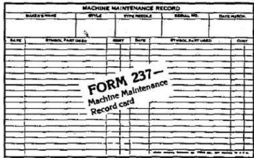
text_image
MACHINE MAINTENANCE RECORD DATE NAME STYLE TYPE ID/000 GENERAL NO. DATE NUMBER: DATE:A SYMBOL PART USED BINJ DATE B SYMBOL PART USED COUNT FORM 237-Machine Maintenance Record cardThe second system is normally used when more detailed information on repair costs is desired. Two record cards are used: a "Repair Request Card" (Form 234), and a "Machine Repair Record" (Form 233). When a machine requires service, the forelady or foreman fills out the top of a "Repair Request Card" and gives it to a mechanic. He fills in the time the repair work is started, the parts used and their cost,
and the completion time. This data is then transferred to the permanent "Machine Repair Record" kept in the office.
Whichever system is used, management now has an invaluable tool to reduce needless maintenance costs.
Repair Part Inventories
While record keeping tells management which machines require abnormally high maintenance, it does little to help reduce the downtime caused by routine repairs. To alleviate this situation, Union Special recommends that manufacturers establish a formal parts inventory system for each type of sewing machine they operate.
Excessive machine downtime and wasted hours by mechanics can be eliminated with an orderly in-plant inventory of the most commonly needed parts. There is no longer a need to cannibalize other machines for spare parts. Long waits for deliveries are avoided and machine downtime is kept to a minimum. The cost of a parts inventory is small when the overall savings are considered.
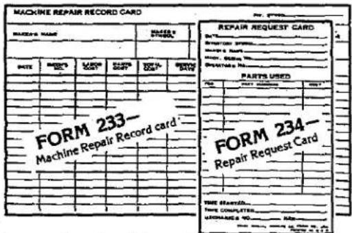
text_image
MACHINE REPAIR RECORD CARD REPAIR REQUEST CARD DATE: 1997 SHEET: 2000 ORDER BY: 2000-03-04 PARTS USED ITEMS PARTS USED TITLE FORM 233- Machine Repair Record card FORM 234- Repair Request Card THIS STARTED. TIME COMPLETTER... INCHANGES TO ....##For free sample copies of the machine record cards and spare part inventory lists for a variety of the most popular machines, contact your local Union Special Representative or write direct to Union Special.
Union Special® Industrial Sewing Equipment
Style 100 P
Suggested Minimum Spare Parts List*
| Part Number | Description | Minimum Quantity Per 5 Machines | Part Number | Description | Minimum Quantity Per 5 Machines |
| C1015 P | Presser Foot | 1 | C1008 P | Looper Hook | 1 |
| 22775 | Screw for Presser Foot | 1 | C717 | Screw for Looper Hook | 2 |
| C1016 P | Feed Dog | 1 | 61453 | Take-up Spring | 3 |
| 22768 | Screw for Feed Dog | 2 | 61470 F | Needle Bar Bushing Thread Guide | 2 |
| C1017 P | Throat Plate | 1 | C1023 | Plunger | 1 |
| 376 | Screw for Throat Plate | 2 | 18-134 | Screw for Plunger | 2 |
| 29-C150 | Needles (specify size) Eye Needle | 200 | C1018 | Thread Retainer | 1 |
| 29-C151 | Needles (specify size) Hook Needle | 200 | 18-45 | Screw for Retainer | 1 |
| C1021 P-062 | Needle Spacer | 2 | 29484 | Screw Assortment | 1 |
| 22562 | Needle Set Screw | 2 |

natural_image
World map projection showing continents and latitude/longitude lines (no text or labels)WORLDWIDE SALES AND SERVICE
Union Special Corporation maintains sales and service facilities throughout the world. These offices will aid you in the selection of the right sewing equipment for your particular operation. Union Special Corporation representatives and service technicians are factory trained and are able to serve your needs promptly and efficiently. Whatever your location, there is a qualified representative to serve you.
Corporate
Office:
One Union Special Plaza
Huntley, IL 60142
Phone: 847-669-5101
Fax: 847-669-4454
European Distribution Center:
Union Special GmbH
Ralfelsenstrasse 3
D-71696 Möglingen, Germany
Tel: 49-07141-247-0
Fax: 49·7141·247·100
Brussels, Belgium
Charlotte, N.C.
El Paso, TX
Hong Kong, China
Huntley, IL
Leicester, England
Lille, France
Miami, FL
Milan, Italy
Möglingen, Germany
Montreal, Quebec
Osaka, Japan
Santa Fe Springs, CA
Other Representatives throughout all parts of the world.

Finest Quality
Union Special® INDUSTRIAL SEWING EQUIPMENT