FS316L62 - Sewing machine Union Special - Free user manual and instructions
Find the device manual for free FS316L62 Union Special in PDF.

User questions about FS316L62 Union Special
0 question about this device. Answer the ones you know or ask your own.
Ask a new question about this device
Download the instructions for your Sewing machine in PDF format for free! Find your manual FS316L62 - Union Special and take your electronic device back in hand. On this page are published all the documents necessary for the use of your device. FS316L62 by Union Special.
USER MANUAL FS316L62 Union Special
OPERATOR / ILLUSTRATED PARTS MANUAL
text_image
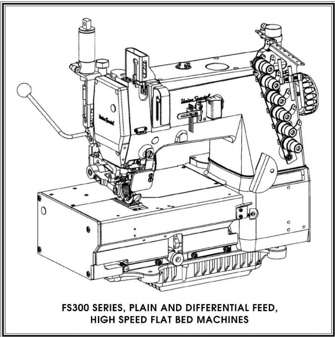
FS300 SERIES, PLAIN AND DIFFERENTIAL FEED, HIGH SPEED FLAT BED MACHINESMANUAL NO. PT9914
FOR STYLES
FS315L63
FS316L61
FS316L62
FS316L63
First Edition Copyright 2000
By
Union Special Corporation Rights Reserved In All Countries
This parts manual has been prepared to assist you in locating individual parts or assemblies on FS300 Series machines. It can be used in conjunction with Union Special Engineer's Manual EN9424.
It is the desire of Union Special that each machine run at its optimum performance. Parts listed in this manual are designed specifically for your machine and are manufactured with utmost precision to assure long lasting service.
This manual has been comprised on the basis of available information. Changes in design and/or improvements may incorporate a slight modification of configuration in illustrations or part numbers.
On the following pages are illustrations and terminology used in describing the parts used on FS300 Series machines.
CONTENTS
PREFACE 2
IDENTIFICATION OF MACHINES 4
CLASS DESCRIPTION 4
STYLE OF MACHINES 4
STYLE OF MACHINES CONT. 5
ILLUSTRATIONS....5
IDENTIFYING PARTS 5
NEEDLES 5
SAFETY RULES 6
FS300 SERIES BUILDING BLOCK STYLE DESIGNATION SYSTEM....7
CAUTION AREAS: 8
OPERATOR'S DAILY CHECK LIST: 9
OPERATING CAUTIONS: 9
OPERATING CAUTIONS (CONT.): 10
OPERATING THE PEDALS: 10
LUBRICATION: 11
THREADING THE MACHINE: 12
THREADING THE MACHINE (CONT.): 13
THREADING METHODS 14
ADJUSTING THE STITCH LENGTH: 15
PRESSER FOOT PRESSURE AND LIFTER: 15
FEED, NEEDLE LOOPER TIMING: 16
NEEDLE ALIGNMENT: 16
LOOPER SETTING: 17
NEEDLE BAR SETTING: 17
REAR NEEDLE GUARD: 18
FEED DOG CENTERING AND HEIGHT ABOVE THROAT PLATE: 18
PRESSER FOOT: 18
LOOPER THREAD TAKE-UP CAM SETTING: 19
THREAD CONTROL: 19
PULLER ADJUSTMENTS: 20
PULLER ADJUSTMENTS CONT.: 21
BUSHINGS 23
NEEDLE BAR 25
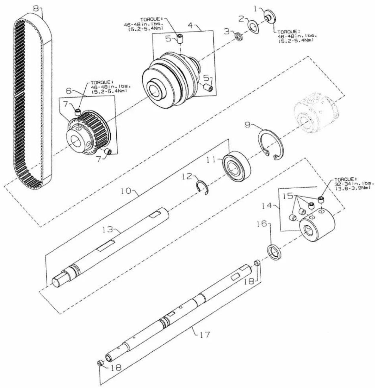
UPPER MAIN SHAFT 27
THREAD GUIDE 29
TENSION RELEASE & THREAD TENSION 31
PRESSER FOOT LIFT 33
COVERS, UPPER ARM 35
LOWER MAIN SHAFT 37
LUBRICATION, OIL TUBING & OIL PUMP 39
LOOPER DRIVE 41
NEEDLE GUARD 43
LOOPER THREAD TAKE-UP 45
FEED DRIVE MECHANISM FOR PLAIN FEED 47
FEED DRIVE MECHANISM FOR DIFFERENTIAL FEED 49
FEED DRIVE MECHANISM FOR PLAIN FEED 51
FEED DRIVE MECHANISM FOR DIFFERENTIAL FEED 53
COVERS, LOWER BED 55
COVERS, LOWER BED 57
SEWING PARTS 59
FOLDERS 61
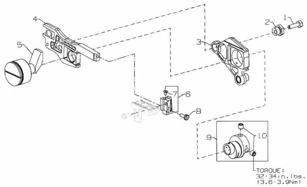
PULLER DRIVE ASSEMBLY 63
PULLER ASSEMBLY 65
PULLER ASSEMBLY 67
MISCELLANEOUS PARTS PA1 (USE WITH CC2 CHAIN CUTTER) 69
MISCELLANEOUS PARTS PA1A (USE WITHOUT CC2 CHAIN CUTTER) 71
TUBING PA1 WITH CHAIN CUTTER 72
TUBING PA1A WITHOUT CHAIN CUTTER 73
TABLING (EXTRA SEND CHARGE) 75
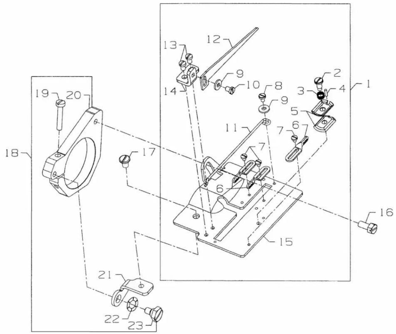
PRESSER FOOT LIFTER 77
ACCESSORIES 79
NUMERICAL INDEX OF PARTS 80
NUMERICAL INDEX OF PARTS 81
IDENTIFICATION OF MACHINES
Each UNION SPECIAL machine is identified by a style number, which is stamped into the style plate affixed to the middle of the machine under the tension assembly. The serial number is stamped into the serial number plate affixed to the right rear base of the machine.
CLASS DESCRIPTION
Precision high speed, single needle, plain or differential feed flat bed machines. Totally enclosed feed and looper drive mechanism, automatic forced feed lubrication system with easily replaceable filter. Main feed has thumbscrew adjustment and differential feed has lever adjustment and independently driven rear needle guard.
STYLE OF MACHINES
| FS316L61-3H36CC2PA1 | DOUBLE LAP SEAM. Three needle, plain feed, high capacity, flat sewing parts, close-coupled toothed roller puller, pneumatic power "AIR-KLIPP" Chain cutter, pneumatic assisted presser foot and roller lift, and double lap seam folder with 1/8"(3.2mm) capacity. For attaching the risers to jeans, seat seaming operations on jeans, bibs to overalls and piecing sleeves on denim jackets. Seam Specifications 401LSc-3. Recommended needle 128 GAS sizes 140/054 - Stitch range 7-10 S.P.I.. Maximum recommended speed 6000 R.P.M. |
| FS316L61-3H36PA1 | DOUBLE LAP SEAM. Three needle, plain feed, high capacity, flat sewing parts, close-coupled toothed roller puller, pneumatic assisted presser foot and roller lift, and double lap seam folder with 1/8"(3.2mm) capacity. For attaching the risers to jeans, seat seaming operations on jeans, bibs to overalls and piecing sleeves on denim jackets. Seam Specifications 401LSc-3. Recommended needle 128 GAS sizes 140/054 - Stitch range 7-10 S.P.I.. Maximum recommended speed6000 R.P.M.. |
| FS316L62-3H36CC2PA1 | DOUBLE LAP SEAM. Three needle, plain feed, high capacity, .040" stepped chaining sewing parts, close-coupled toothed roller puller, pneumatic power "AIR-KLIPP" Chain cutter, pneumatic assisted presser foot and roller lift, and double lap seam folder with 1/8"(3.2mm) capacity. For attaching the risers to jeans, seat seaming operations on jeans, bibs to overalls and piecing sleeves on denim jackets. Seam Specifications 401LSc-3. Recommended needle 128 GAS 140/054 - Stitch range 7-10 S.P.I.. Maximum recommended speed 6000 R.P.M.. |
| FS316L62-3H36PA1 | DOUBLE LAP SEAM. Three needle, plain feed, high capacity, .040" stepped chaining sewing parts, close-coupled toothed roller puller, pneumatic assisted presser foot and roller lift, and double lap seam folder with 1/8"(3.2mm) capacity. For attaching the risers to jeans, seat seaming operations on jeans, bibs to overalls and piecing sleeves on denim jackets. Seam Specifications 401LSc-3. Recommended needle 128 GAS sizes 140/054 - Stitch range7-10 S.P.I.. Maximum recommended speed 6000 R.P.M.. |
| FS316L63-3H32CC2PA1 | DOUBLE LAP SEAM. Three needle, plain feed, high capacity, .070" stepped chaining sewing parts, close-coupled toothed roller puller, pneumatic power "AIR-KLIPP" Chain cutter, pneumatic assisted presser foot and roller lift, and double lap seam folder with 1/8"(3.2mm) capacity. For attaching the risers to jeans, seat seaming operations on jeans, bibs to overalls and piecing sleeves on denim jackets. Seam Specifications 401LSc-3. Recommended needle 28 GAS sizes 140/054 - Stitch range 7-10 S.P.I.. Maximum recommended speed 6000 R.P.M.. |
| FS316L63-3H32PA1 | DOUBLE LAP SEAM. Three needle, plain feed, high capacity, .070" stepped chaining sewing parts, close-coupled toothed roller puller, pneumatic assisted presser foot and roller lift, and double lap seam folder with 1/8"(3.2mm) capacity. For attaching the risers to jeans, seat seaming operations on jeans, bibs to overalls and piecing sleeves on denim jackets. Seam Specifications 401LSc-3. Recommended needle 128 GAS sizes 140/05A - Stitch range 7-10 S.P.I.. Maximum recommended speed 6000 R.P.M.. |
STYLE OF MACHINES CONT.
FS315L63-3H32CC2PA1 Same as FS316L63-3H32CC2PA1 except differential feed.
FS315L63-3H32PA1 Same as FS316L63-3H32PA1 except differential feed.
ILLUSTRATIONS
This manual has been arranged to simplify ordering repair parts. Exploded views of various sections of the mechanism are shown so that the parts may be seen in their actual position in the machine. On the page opposite the illustration will be found a listing of the parts with their part numbers, description and the number of pieces required in the particular view being shown.
Numbers in the first column are reference numbers only, and merely indicate the position of the part in the illustration. The reference number should never be used in ordering parts. Always use the part number listed in the second column.
Component parts of sub-assemblies which can be furnished for repairs are indicated by indenting their descriptions under the description of the main sub-assembly. As an example refer to the following text.
- 50366B Needle Thread Strike-Off Assembly 1
- 50358V Needle Thread Strike-Off .... 1
- 50370F Thread Strike-Off Component .... 1
- SS7060310SP Screw, for plate strike-off 1
When a part is common to all machines covered in this manual, no specific usage will be mentioned in the description. However, when the parts for the various machines are not the same, the specific usage will be mentioned in the description and, if necessary, the difference will be shown in the illustration.
*Ref. No. showing no Part No. is for location only. Part is not for sale separately.
A numerical index of all the parts shown in this manual is located at the back. This will facilitate locating the illustration and description when only a part number is known.
IDENTIFYING PARTS
Where construction permits, each part is stamped with its part number. On some of the smaller parts and on those where construction does not permit, an identification letter is stamped in to distinguish the part from similar ones.
PLEASE NOTE: Part numbers represent the same part, regardless of which manual they appear. On all orders please include part number, name and style of machine for which the part was ordered.
For optimum performance use only genuine Union Special replacement parts.
NEEDLES
Each needle has both a type and size number. The type number denotes the kind of shank, point, length, groove, finish and other details. The size number, stamped on the needle shank, denotes the largest diameter of the blade measured between the shank and the eye. Collectively, the type number and size number represent the complete symbol which is given on the label of all needles packed and sold by Union Special.
TYPE DESCRIPTION
128 GAS Short, double groove, struck groove, ball eye, spotted, round point, chromium plated- Sizes available 080/032, 090/036, 100/040, 110/044, 125/049, 150/060.
When changing the needle, make sure it is fully inserted in the needle holder before the screw is tightened.
When ordering needles, please use the complete type and size numbers as printed on the package to ensure prompt and accurate processing of your order. A complete order should read as follows: "100 needles, type 128 GAS, size 150/060".
SAFETY RULES
- Before putting the machines described in this manual into service, carefully read the instructions. The starting of each machine is only permitted after taking notice of the instructions and by qualified operators.
IMPORTANT! Before putting the machine into service, also read the safety rules and instructions from the motor supplier.
-
Observe the national safety rules valid for your country.
-
The sewing machines described in this instruction manual are prohibited from being put into service until it has been ascertained that the sewing units which these sewing machines will be built into, have conformed with the EC Council Directives (89/392/EEC, Annex II B).
Each machine is only allowed to be used as foreseen. The foreseen use of the particular machine is described in paragraph "STYLES OF MACHINES" of this instruction manual. Another use, going beyond the description, is not as foreseen.
-
All safety devices must be in position when the machine is ready for work or in operation. Operation of the machine without the appertaining safety devices is prohibited.
-
Wear safety glasses.
-
In case of machine conversions and changes all valid safety rules must be considered. Conversions and changes are made at your own risk.
-
The warning hints in the instructions are marked with one of these two symbols:

- When doing the following the machine has to be disconnected from the power supply by turning off the main switch or by pulling out the main plug:
8.1 When threading needle(s), looper, spreader etc.
8.2 When replacing any parts such as needle(s), presser foot, throat plate, looper, spreader, feed dog, needle guard, folder, fabric guide etc.
8.3 When leaving the workplace and when the workplace is unattended.
8.4 When doing maintenance work.
8.5 When using clutch motors without actuation lock, wait until the motor is stopped totally.
-
Maintenance, repair and conversion work (see item 8) must be done only by trained technicians or special skilled personnel under consideration of the instructions.
-
Any work on the electrical equipment must be done by an electrician or under direction and supervision of special skilled personnel.
- Work on parts and equipment under electrical power is not permitted. Permissible exceptions are described in the applicable sections of standard sheet DIN VDE 0105.
- Before doing maintenance and repair work on the pneumatic equipment, the machine has to be disconnected from the compressed air supply. In case of existing residual air pressure, after disconnecting from compressed air supply (i.e. pneumatic equipment with air tank), the pressure has to be removed by bleeding.
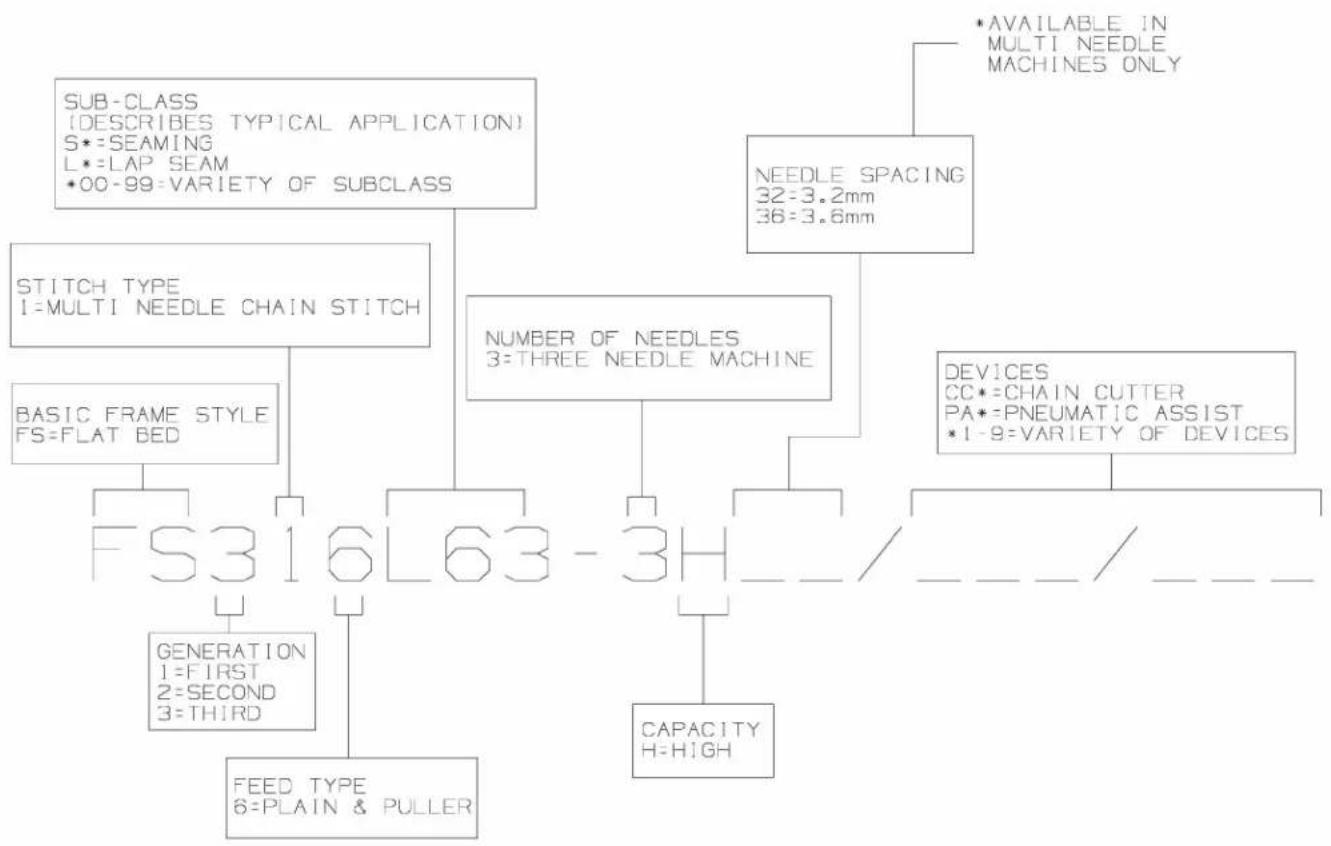
FS300 SERIES BUILDING BLOCK STYLE DESIGNATION SYSTEM
flowchart
graph TD
    A["SUB-CLASS<br>(DESCRIBES TYPICAL APPLICATION)<br>S*=SEAMING<br>L*=LAP SEAM<br>*00-99=VARIETY OF SUBCLASS"] --> B["STITCH TYPE<br>I=MULTI NEEDLE CHAIN STITCH"]
    A --> C["NEEDLE SPACING<br>32=3.2mm<br>36=3.6mm"]
    A --> D["NUMBER OF NEEDLES<br>3=THREE NEEDLE MACHINE"]
    A --> E["BEAS DEVICES<br>CC*=CHAIN CUTTER<br>PA*=PNEUMATIC ASSIST<br>*1-9=VARIETY OF DEVICES"]
    B --> F["BASIC FRAME STYLE<br>FS=FLAT BED"]
    F --> G["FS316L63-3H"]
    G --> H["FEED TYPE<br>6=PLAIN & PULLER"]
    G --> I["GENERATION<br>1=FIRST<br>2=SECOND<br>3=THIRD"]
    G --> J["CAPACITY<br>H=HIGH"]
    G --> K["*AVAILABLE IN MULTI NEEDLE MACHINES ONLY"]
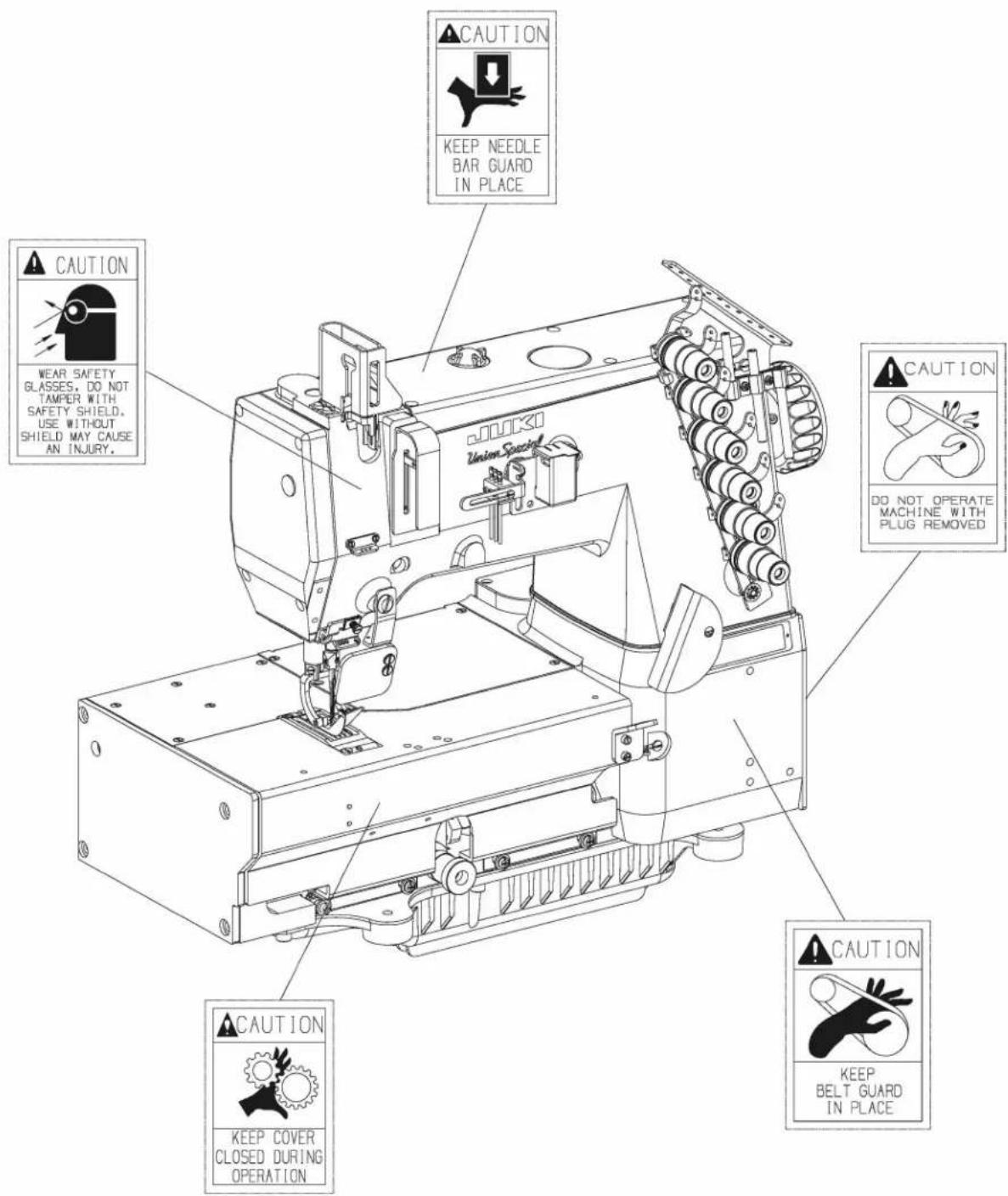
CAUTION AREAS:
text_image
CAUTION KEEP NEEDLE BAR GUARD IN PLACE WEAR SAFETY GLASSES, DO NOT TAMPER WITH SAFETY SHIELD, USE WITHOUT SHIELD MAY CAUSE AN INJURY. QUICKI Union Spectral CAUTION DO NOT OPERATE MACHINE WITH PLUG REMOVED CAUTION KEEP COVER CLOSED DURING OPERATION CAUTION KEEP BELT GUARD IN PLACEOPERATOR'S DAILY CHECK LIST:
The following should be checked daily and cleaned as required when it applies to your Union Special machine:
••Lint area (clean with compressed air or brush)
- Needle bar bushings
• Under feed dogs & throat plates
••In knives
••In thread control eyelets
••Cooling airways
••In the machine
••In the motor
••In the cooling package
(package is an extra send charge)
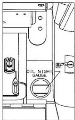
text_image
OIL SIGHT GAUGE- The oil level in the sight gauge should be between the two red lines when the machine is at rest. If not, fill with Union Special Specification 175 oil, (Union Special Part No. 28604R).
natural_image
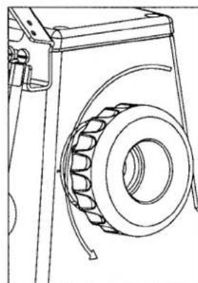
Technical line drawing of a mechanical component with a coiled spring and housing (no text or symbols)- The correct rotating direction of the handwheel is counterclockwise, as viewed from the handwheel's side. NEVER run the machine in reverse direction.
OPERATING CAUTIONS:


natural_image
Technical line drawing of a sewing machine mechanism (no text or symbols)- Do not put your hand under the needles when turning on the power switch or at any time.

natural_image
Line drawing of a sewing machine needle and handle assembly (no text or symbols)- Do not put your hand into the sewing area while the machine is running.
text_image
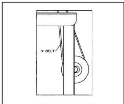
V DELT- Turn off the power switch and make sure the clutch motor is at rest before removing the V belt.
OPERATING CAUTIONS (CONT.):

- During operation, do not allow head, hands or any instrument, tool etc. near handwheel, V belt and motor.
- Do not operate your machine without the proper belt guard, sewing guards or any other protectors that have been provided. Doing so is very dangerous.
- Before inspecting, adjusting, cleaning, threading the head or replacing needles, turn OFF the power switch. Make sure the flywheel on the motor has stopped, it will be kept running by inertia after turning OFF the power switch. DO NOT depress the foot pedal while the machine is running or it will cause the machine to rotate abruptly.
- Turn OFF the power switch when you leave your machine or in case of a power failure.
- Do not wipe the machine surface with lacquer thinner.
OPERATING THE PEDALS:
text_image
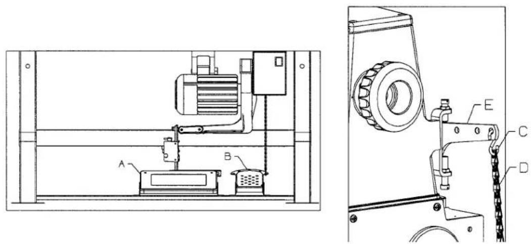
Technical schematic diagram of a mechanical device with labeled components A, B, C, D, and E- Locate the center of drive treadle (A) to be in line with the needles.
- Locate presser lifter pedal (B) for operator comfort.
- Use S-shaped hook (C) to connect presser lifter pedal chain (D) to presser lifting lever (E).
LUBRICATION:

text_image
Technical diagram of a mechanical assembly with labeled components A, B, C, D and an inset view of a gear mechanism.The oil should be between the two red lines in sight gauge (B) when the machine is at rest.
-
If oil is required remove oil cap (A).
-
Fill between lines (B) with Union Special Specification 175 oil (Union Special Part No. 28604R).

CAUTION! Do not exceed the upper red marker line. Excessive oil in the machine will result in oil leakage and possible overheating.
-
To drain oil reservoir, remove oil drain cap (C) on the underside of the machine.
-
To ensure oil flow through machine, check oil flow window (D).
THREADING THE MACHINE:
Turn off main power switch before threading! When using clutch motors without actuation lock wait until the motor has completely stopped.
Thread the machine according to the following threading illustrations.
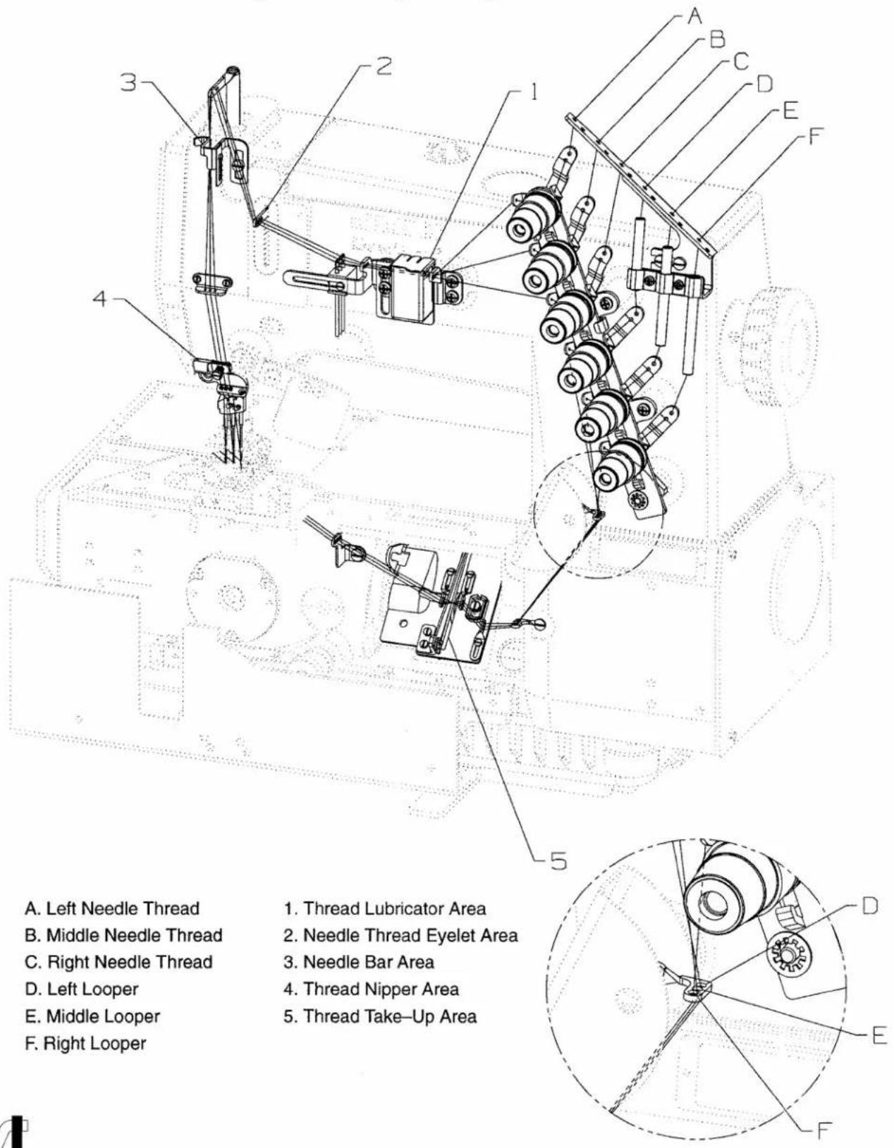
text_image
A. Left Needle Thread B. Middle Needle Thread C. Right Needle Thread D. Left Looper E. Middle Looper F. Right Looper 1. Thread Lubricator Area 2. Needle Thread Eyelet Area 3. Needle Bar Area 4. Thread Nipper Area 5. Thread Take-Up AreaTHREADING THE MACHINE (CONT.):
natural_image
Technical line drawing of a mechanical clamp or bracket assembly (no text or symbols)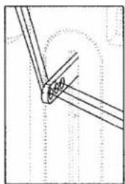
natural_image
Pure technical line drawing of a mechanical joint or bracket (no text or symbols)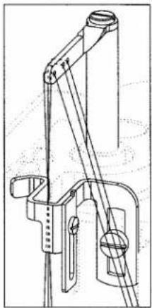
natural_image
Technical line drawing of a mechanical lifting device (no text or symbols)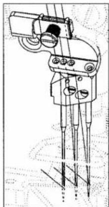
natural_image
Technical line drawing of a mechanical device with multiple pins and adjustment knobs (no text or symbols)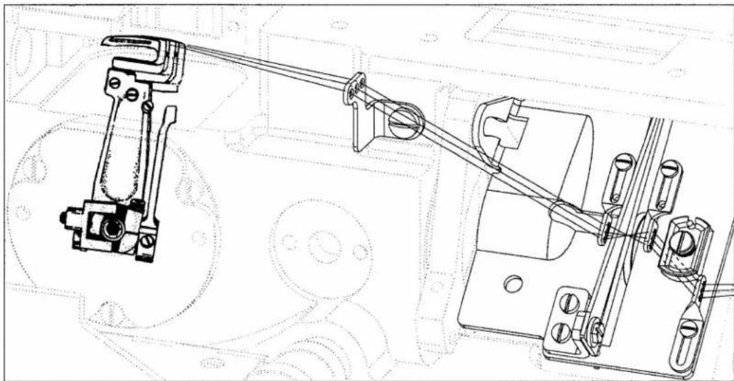
natural_image
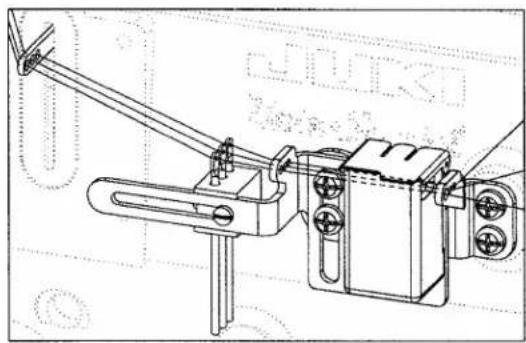
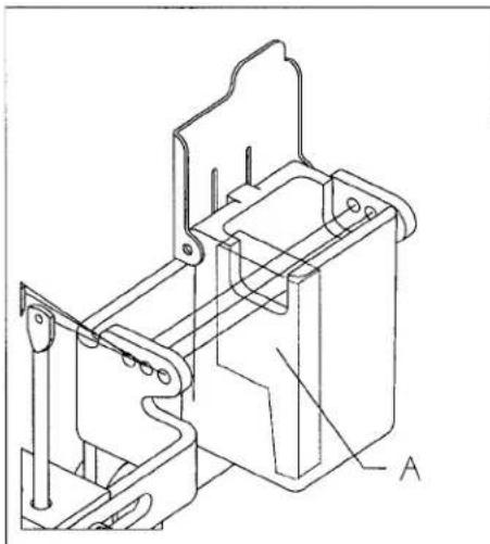
Technical line drawing of a mechanical assembly with linkage and housing components (no text or symbols)threading the machine (cont.):
When the needle thread lubricator is used:
- Saturate felt (A).
- Pass thread over felt.
When the needle thread lubricator is not used:
- Remove felt (A).
natural_image
Technical line drawing of a mechanical assembly with no visible text or symbols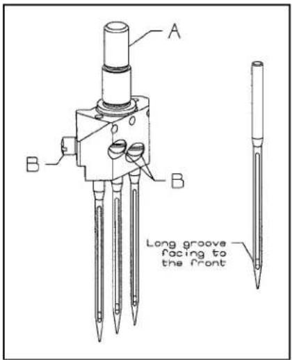
text_image
A B B Long groove facing to the FrontThe standard needle is 128 GAS, needle range sizes "090/036 - 150/060." Insert needle according to the following procedure:
- Bring needle head (A) to the highest position.
- Loosen screw (B), insert needle into holes. The needle scarf should face rearwards as viewed from the operator's side.
- Retighten screw (B).
THREADING METHODS

CAUTION!
When using an untwisted thread such as wooly nylon or weak thread, do not wind it around the intermediate thread guide.
Twisted Thread
natural_image
Pure technical line drawing of a pipe connection with no text, numbers, or symbolsNon-Twist Thread

natural_image
Pure technical line drawing of pipe connections without any text, numbers, or symbolsPRESSER FOOT PRESSURE AND LIFTER:
-
Adjust presser foot pressure by loosening nut (A) and turning presser foot adjust screw (B) clockwise to increase the pressure, counterclockwise to decrease the pressure.
-
Retighten nut (A).

text_image
Technical diagram of a mechanical device with labeled components A and BADJUSTING THE STITCH LENGTH:
Turn off main power switch before setting the stitch length! When using clutch motors without actuation lock wait until the motor has completely stopped.
- To change stitch length turn stitch regulating screw (A).
Clockwise to increase the stitches per inch/shorten the length of one stitch.
Counterclockwise to decrease stitches per inch/increase the length of one stitch.
- Numbers 0-11 on stitch regulating screw are for operator's reference only.

text_image
Numbers 0-11 AFEED, NEEDLE LOOPER TIMING:
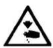
Set the first screw in operating direction of the feed drive eccentrics to be straight up, then, holding this position, set the needle bar at B.D.C.. Set the looper timing to the needles to be synchronized. Adjust the looper timing with the looper avoid drive sprocket.
text_image
For Proper SYNCHRONIZATION of Looper & Needle these two Dimensions will be the same Looper BEHIND Needle in OPERATING Direction Looper in FRONT of Needle in REVERSE DirectionNEEDLE ALIGNMENT:
Torque needle head to 14 to 16 in-lbs (1.6 to 1.8Nm).
Install the feed dog, needles and throat plate. Use the adjustable ferrules to align the needles in the throat plate and align the feed dog so it is centered side to side, tighten the throat plate support and ferrules in place.

text_image
Center Feed Dog In Center Of Feed Slots Centered 3 PlacesLOOPER SETTING:
Use the right needle and looper to set the looper gauge. Set the looper gauge to 1/8" (3.2mm) when loopers at extreem right. Set the loopers front to back to deflect the needles forward .002" to .006" (.05mm to .10mm). set the looper avoid so the needle touches the back of the looper 2/3 down back as needles descend.

text_image
1/8" (3.2mm) Needle tip 2/3 Looper Deflect Needle .002"-.006" (.05mm-.15mm)NEEDLE BAR SETTING:
Set the needle height so when the top of the needle eye is even with the bottom of the looper (on it's travel to the left) the looper tip is .020" (.5mm) past the needle. Use the left needle. Recheck looper setting. Torque needle bar clamp screw to the following specifications:
Torque needle bar@18 to 20 in.-lbs. (2.0 to 2.3Nm)

text_image
.020 (.5mm) Looper AlignREAR NEEDLE GUARD:
Set the timing of the rear needle guard so the guard reaches it's furthest travel forward as the loopers enter the scarfs on the travel to the left.
Bring the looper tips to the center of the needles in the scarf. The tip of the needles should be 3/64" +/-1/64" (1.2mm +/- .4mm) below the top guarding surface. The guard should just touch the needles up to .002 (.05mm) deflection. The loopers when traveling to the left should just touch the needles to .002" (.05mm) clearance when entering the scarf area.

FEED DOG CENTERING AND HEIGHT ABOVE THROAT PLATE:
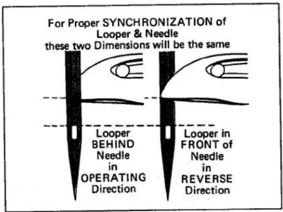
Set the machine to its longest stitch length. Center feed dog, front to back, so as to obtain equal clearance on the front side and back side of feed dog in the throat plate slots. Set the feed dogs to come out of the throat plate level. Set feed dog height to be full tooth at the rear when the feed dog is at the top of its stroke.
text_image
A Full Tooth APRESSER FOOT:
Center the needles in the presser foot needle slots. The presser foot lifter lever stop should be set to when the foot is lifted it does not interfere with the needle head when the needle bar is down.
LOOPER THREAD TAKE-UP CAM SETTING:
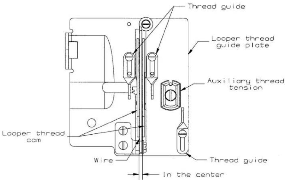
The looper thread cam should be set so that the looper threads cast off the high lobe of the cam as the point of the needles are just even with the under side of the looper. Set the cast-off plate eyelets so that when the looper reaches its left end of travel, all of the looper thread is used and no thread is drawn from the cone. Move down for less. Set the retaining finger so that the finger is even with the bottom edge of its holder and the tip on the right side is touching the cast-off plate.
text_image
Thread guide Looper thread guide plate Auxiliary thread tension Looper thread cam Wire Thread guide In the centerTHREAD CONTROL:
Set the individual needle thread eyelets so they are 25mm below the top casting and to the extreme right when using the mount adapter.
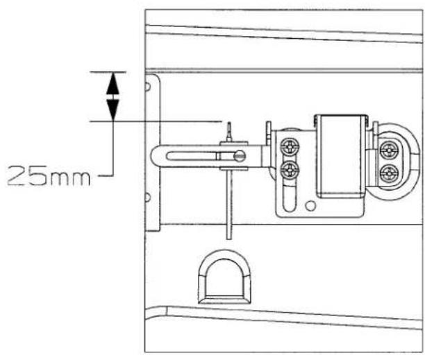
text_image
25mmPULLER ADJUSTMENTS:
With the roller resting on the top of the throat plate, the stop collar should be set about 15mm above the ledge of the puller casting where the stop screw rests. Set the stop screw to rest on the casting and lock in place. Set the lifter lever block to have 0.05mm to 0.15mm clearance above the lifter lever in the neutral position.
Note: When changing sprockets, if the total number of teeth on both sprockets is different than what was on the puller, check and readjust these settings.

text_image
15.0mm 0 0.05mm 0.15mmUse the puller tension nut to add or remove pressure from the roller.
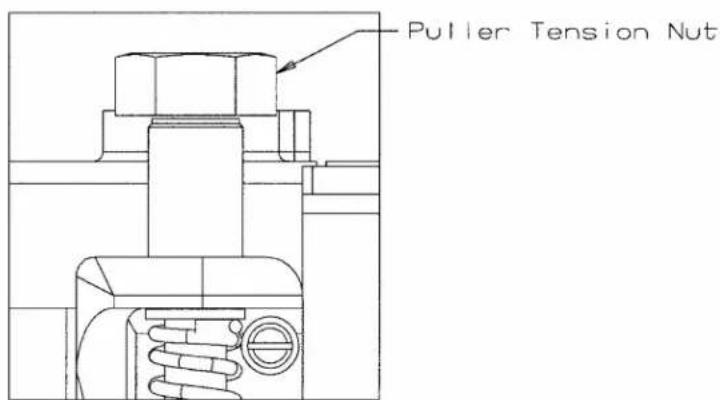
text_image
Puller Tension NutPULLER ADJUSTMENTS CONT.:
When assembling the puller to the machine, make sure that a minimum of .05 clearance is maintained between the roller and the throat plate step. Also the roller must sit flat on the throat plate.
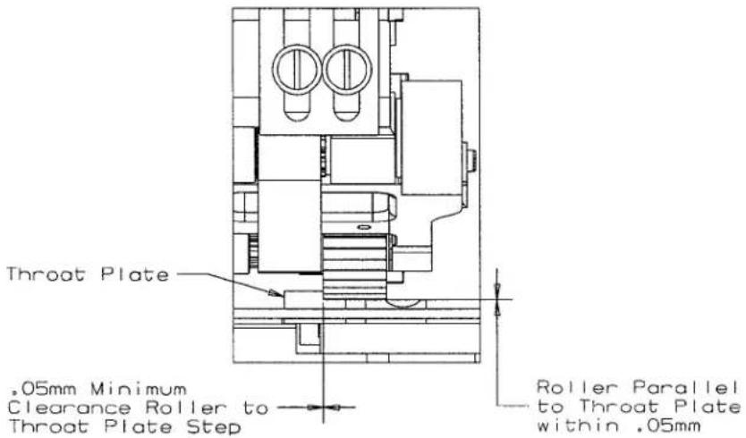
text_image
Throat Plate .05mm Minimum Clearance Roller to Throat Plate Step Roller Parallel to Throat Plate within .05mmTime the puller so the roller feeds at the same time the feed dog is feeding. When setting, both should be feeding at the same S.P.I.. Adjust the timing by using the sprocket on the upper main shaft in the arm.
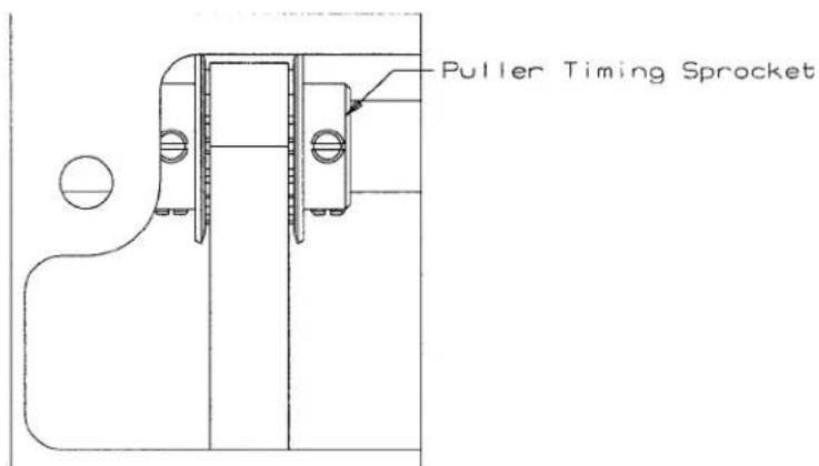
text_image
Puller Timing Sprocket| SNOITANIBMOCTEKCORPSRELLUF | ||
| EVIRDRELLURELLUP .R/STEKCORPS TEKCORPS HCTS | ||
| 41 | 15 | 8 |
| 14 | 14 | 7 1/2 |
| 51 | 14 | 7 |
| 15 | 13 | 6 1/2 |
| 13 | 15 | 8 1/2 |
| 13 | 16 | 9 |
| 61 | 13 | 6 |
| 12 | 16 | 9 1/2 |
| 11 | 16 | 10 |
text_image
Technical diagram of a mechanical assembly with numbered components for identificationBUSHINGS
Ref.
No. Part No. Description
Amt.
Req.
- 50654 Bushing, for needle bar, upper 1
- 50332U Pin, for front lifter lever 1
- 50330CZ Bushing, for presser bar 1
- 50654A Bushing, for needle bar, lower 1
- 50344BE Bushing, for lower mainshaft, left 1
- SQ1110401MZ Fitting 1
- 50344BC Bushing, for needle lever 1
- 50344E Bushing 1
- 50344BF Bushing, for lower mainshaft, right 1
- 35036BS Stitch Regulator Bushing 1
- 50393GE Oil Sight Gauge 1
- 22571L Screw, for drain plug 1
- 50393FU Fitting, oil tube 1
- 50393EY Fitting, filter 1
- 50392AB Bushing, for tension release.... 1
- PS0400142KH Pin 1
- 50381E Bushing, for lifter lever, back.... 1
- 50344BU Bushing, front 1
- SQ1110401MZ Fitting 1

text_image
TORQUE: 18-20in. Ibs. (2.0-2.3Nm) TORQUE: 18-20in. Ibs. (2.0-2.3Nm) 1 2 3 4 5 6 7 8 9 10 11 12 13 14 15 16 17 18 19 20 21 22 23 24 25 Three Bond: Union Special No. CE63 Loctite: Union Special No. CE59 LOctite: Union Special No. CE27NEEDLE BAR
Ref.
No. Part No.
Description
Amt.
Req.
- SS4080620TP Screw 1
- 50323P Needle Bar Eyelet 1
- 50317B Needle Bar 1
- 50345W Connecting Rod Assembly 1
- 50355AM Needle Bar Clamp 1
- SS7111120TP Screw 1
- 50352 Pivot Pin 1
- 661-259B Needle Bearing Cage 1
- 50355AN Connecting Rod 1
- 50351A Washer 1
- 50393JP Eyelet Seal 1
- 50358X Needle Thread Eyelet 1
- SS7080520SP Screw 1
- CE27 Loctite Adhesive, (not shown), for screw
- 50354F Slide Block 1
- CE63 Three Bond Adhesive, (not shown), for slide block ....
- SS8110422TP Screw 1
- 29476TC Oil Tube Assembly 1
- 50393JZ Oil Tube 1
- 50393JW Hose Clamp 1
- SS6090440SP Screw, for oil tube assembly 1
- SS6121010SP Screw 2
- 29476VN Slide Block Guide and Cover Assembly 1
- 50338 Guide, for slide block 1
- 666-328 Felt, for slide block 1
- CE59 Loctite Adhesive, (not shown), for felt ....
- 50338A Cover, for guide 1
- SS6090620SP Screw 1

text_image
TORQUE: 46-48in, lbs. (5.2-5.4Nm) TORQUE: 32-34in, lbs. (3.6-3.9Nm) TORQUE: 54-56in, lbs. (6.0-6.3Nm) TORQUE: 54-56in, lbs. (6.0-6.3Nm) TORQUE: 46-48in, lbs. (5.2-5.4Nm)UPPER MAIN SHAFT
Ref.
No. Part No.
Description
Amt.
Req.
- 50322BC Upper Main Shaft Assembly 1
- 50691 Counter Weight 1
- SS7111120TP Screw, for counter weight 1
- SS7681410TP Screw, for counter weight 1
- SS8681412TP Screw, for counter weight 1
- 50322AF Upper Main Shaft 1
- 50642A Sprocket, Main Drive 1
- 22894T Screw 4
- 50335BD Bearing Adapter Assembly 1
- SS8660612TP Screw, for bearing adapter 2
- 661-262 Retaining Ring 1
- 50342BE Sprocket, for upper main shaft 1
- SS8661012TP Set Screw, for sprocket 2
- 660-1087 "O" Ring.... 1
- 50321F Handwheel.... 1
- SS8681412TP Set Screw, for handwheel 2
- 660-1043 Tack Pin, for handwheel 1
- 661-261 Load Ring, for lower main shaft 2
- SS7660520SP Screw, for handwheel preload 1

text_image
Technical diagram of a mechanical assembly with numbered components and exploded views, likely for assembly or maintenance.THREAD GUIDE
Ref.
No. Part No.
Description
Amt.
Req.
- SS7120640SP Screw, for lead-in eylet 2
- 50666A Thread Eyelet Assembly 1
- SS4090815SP Screw 2
- 50666 Tube Bracket 2
- 50692E Lead-In Tension Eyelet 1
- 50666C Thread Tube 1
- 50366 Thread Eyelet Tube 2
- SS4120915SP Screw, for spreader thread guide 2
- 50663A Thread Ratio Control Assembly 1
- 50393HH Silicone Thread Lubricator 1
- 50392V Needle Thread Guide 1
- SS4090815SP Screw, for silicone tank 2
- 36271A Adjusting Needle Thread Eyelet 3
- 50358W Holder, For Needle Thread Eyelet 1
- SS8080410TP Screw 3
- SS7080510TP Screw 1
- 50683 Mounting Bracket 1
- 50658B Looper Frame Eyelet 1
- SS7090610SP Screw 1
- SS7120640SP Screw 1
- 50658A Looper Frame Eyelet 1
- SS1121010SP Screw, for thread guide 1
- 50357AE Nipper Plate Assembly 1
- SD0380551SL Screw 1
- 50357AS Nipper Spring 1
- 50357Y Nipper Spring Plate 1
- 50392BA Thread Guide 1
- 50357V Nipper Plate 1
- 605A Screw, for needle thread guide 2
- C50044E Needle Thread Guide 1
- SS7120710SP Screw, for strike-off 1
- 50366B Needle Thread Strike-Off Assembly 1
- SS7060310SP Screw 1
- 50370F Thread Strike-off Component 1
- 50358V Needle Thread Strike-off 1

text_image
Technical diagram of a mechanical assembly with numbered parts and labeled sections (Blue, Purple)TENSION RELEASE & THREAD TENSION
| Ref. | Amt. | ||
| No. | Part No. | Description | Req. |
- 50392Z Tension Needle Lever Assembly 1
- 660-283A Retainer Washer 1
- SS4120915SP Screw, for tension assembly 2
- 50692D Six Thread Tension Assembly 1
- 57892K Thread Tension Eyelet 6
- 56392G Tension Post 6
- B3120352000 Tension Disc Felt 6
- B3126012000 Tension Disc 12
- B3120704000 Tension Disc Felt 6
- 56392H Spring Shield 6
- 11550100 Spring, needle (Purple) 3
- B3103800400 Spring, looper (Blue) 3
- B3112704000 Ferrule, tension spring 6
- 50692J Knob, needle (Purple) 3
- 56392M Knob, looper (Blue) 3
- 50692 Tension Disc Separator 1
- 50392AV Guide, for tension disc separator 2
- SS7090520SP Screw, for guide 2
- 50692A Tension Bracket 1
- 57865 Lead-In Thread Guide 6
- NS6110420SP Nut 6
- 50392BC Tension Release Lever Shaft Connection 1
- 22875N Stop Screw 1
- SS7121410TP Binder Screw 1
text_image
1 2 3 4 5 6 7 8 9 10 11 12 13 14 15 16 17 18 19 20 21 22 23 24 25 26 27 28 Loctite: Union Special No. CE66 (2 screws)PRESSER FOOT LIFT
Ref.
No. Part No.
Description
Amt.
Req.
- 11071602 Adjusting Screw, for spring 1
- 11071701 Locking Nut 1
- 660-1014 "O" Ring 1
- C50056B Spring Rod 1
- 50632A Spring, for presser bar 1
- 50643C Presser Bar 1
- SS6110610TP Screw, for guide plate 2
- 50335AG Guide Plate, for presser bar 1
- 50335AH Presser Bar Guide 1
- SS8110422TP Set Screw 2
- 660-739 Oil Seal 1
- RE0500000K0 E Ring, for pin 1
- 50381F Lever, for lifter, front 1
- SD0790303SP Screw, for wire connector 1
- CE49 Loctite Adhesive, (not shown), for screw
- 29476YD Rear Lifter Lever Assembly 1
- SD0790303SP Screw, for lifter lever assembly 1
- 50355AR Wire Connector 1
- 50381G Lifter Lever, rear 1
- SS9151740CP Hex Screw 1
- 29476TT Stop Assembly 1
- SS6151920SP Screw, for adjusting stopper 1
- NS6150310SP Hex Nut 2
- 50332V Stopper, for lifter lever 1
- SS6153040SP Screw, for adjusting stopper 1
- SS4121215SP Screw, for stopper 2
- CE49 Loctite Adhesive, (not shown), for screw
- 50381 Spring, for lifter lever 1
- RO068190100 "O" Ring 1
- 50381B Lifter Lever Assembly 1
text_image
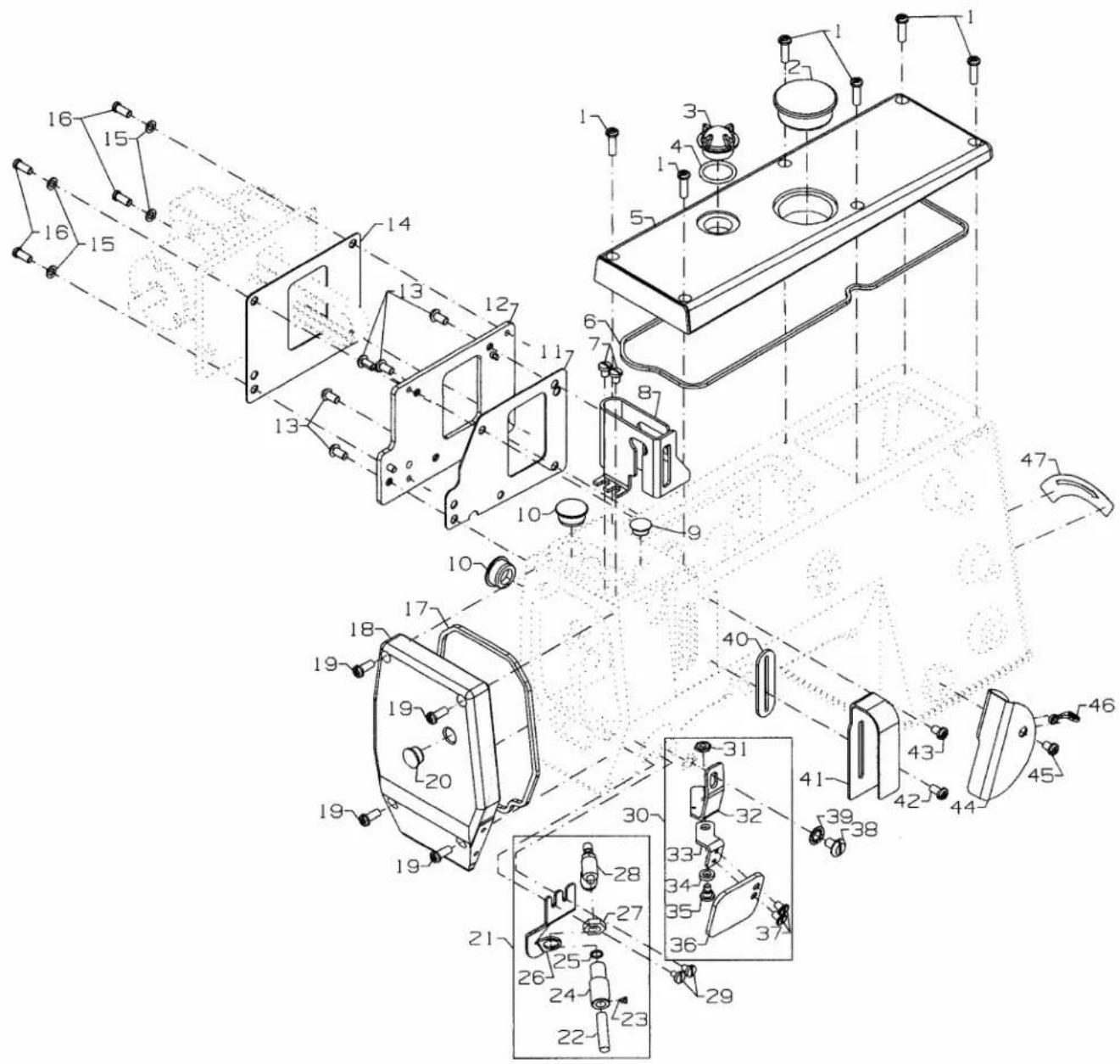
Technical diagram of a mechanical assembly with numbered components and exploded viewsCOVERS, UPPER ARM
Ref.
No. Part No.
Description
Amt.
Req.
- SS4121615SP Screw, for top cover 6
- 50393EU Plug, for top cover 1
- B3530555000 Oil Sight Gauge, top 1
- 660-212 "O" Ring, for oil sight gauge 1
- 50382FW Top Cover 1
- 50382FZ Quad Ring, for top cover 1
- SS7120640SP Screw, for needle bar guard 2
- 50317C Needle Bar Guard 1
- TA1050504RO Plug, for bed 1
- 50393HB Plug, for bed 2
- 50684C Gasket, for puller drive Adapter.... 1
- 50662A Puller Drive Adapter 1
- SS6121050SP Screw, for puller drive adapter 5
- 50684B Gasket, for Puller Drive Housing 1
- WP0480856SP Washer 4
- 22569B Screw 4
- 50382FY Quad Ring, for head cover 1
- 50382FX Head Cover 1
- SS4121215SP Screw, for head cover 4
- TA1100604RO Plug, for head cover 1
- 21237EV Needle Cooler Assembly 1
- 21237DR Cooler Tube 1
- 22784N Screw 1
- 21237ET Cooler Housing 1
- 660-886 O-Ring 1
- 21237EU Bracket 1
- 51170D Nut 1
- 671-102A Flow Control 1
- SS7090610SP Screw 2
- 99682XCA Protection Shield Assembly 1
- NS6620320SP Nut 1
- 99682XC1 Bracket Holder 1
- 99682XC2 Bracket 1
- WZ0641510KP Spring Washer 1
- SD0640323TP Shoulder Screw 1
- 99682XC Protection Shield 1
- SS1110640SL Counter Sunk Head Screw 2
- 22517B Screw 1
- 652C16 Washer 1
- 50393EW Rubber Gasket, for needle lever 1
- 50382GA Cover, for thread take-up 1
- SS4120915SP Screw, for thread take-up cover 1
- SS4120615SP Screw, for thread cover 1
- 50382GM Thread Cover 1
- SS4120615SP Screw, for thread take-up cover 1
- 50658B Eyelet 1
- LA452 Label, direction of rotation 1
* PA1 KIT ONLY
text_image
TORQUE: 46-48in.1bs. (5.2-5.4Nm) TORQUE: 46-48in.1bs. (5.2-5.4Nm) TORQUE: 46-48in.1bs. (5.2-5.4Nm) TORQUE: 32-34in.1bs. (3.6-3.9Nm)LOWER MAIN SHAFT
| Ref. | Amt. | ||
| No. | Part No. | Description | Req. |
-
SS7660520SP Shoulder Screw, for lower main shaft, right 1
-
660-1062 Spring Washer 1
-
50374 Spacer, for pulley assembly 1
-
50321G Pulley Assembly 1
-
SS8661012TP Set Screw 2
-
50342AX Sprocket, for lower main shaft 1
-
SS8660612TP Screw 2
-
50342BS Timing Belt 1
-
50335AK Retaining Ring, for ball bearing 1
-
29476UH Mainshaft Assembly, lower, right 1
-
50322AL Ball Bearing, for lower main shaft 1
-
50335BB Retaining Ring 1
-
50322AG Lower Main Shaft, right 1
-
50333A Coupling, for lower main shafts 1
-
SS8660612TP Screw 4
-
660-934 Oil Seal 1
-
50622D Lower Main Shaft, left for plain feed.... 1
17A. 50622E Lower Main Shaft, left for differential feed 1
- SS8660410SP Screw 2

text_image
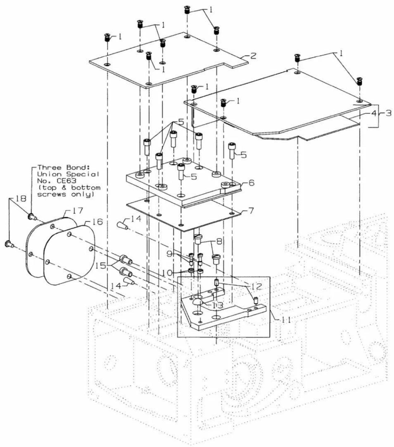
CONNECT 50393BU 35 14 15 16 17 18 20 22 23 20 21 24 20 25 34 26 35 27 29 30 28 27 32 29 31 29 30 29 33 36 35 38 39 40 43 42 41 42 43 44 45 46 47 48 49 10 11 12 TO: CONNECTOR (A) OF OIL PUMP 50393HN TO: CONNECTOR (B) OF OIL PUMP 50393HN TO: CONNECTOR (C) OF OIL PUMP 50393HN TO: SUCTION OIL TUBE 50393HL (MOUNTS TO LOWER BED CASTING)LUBRICATION, OIL TUBING & OIL PUMP
Ref.
No. Part No.
Description
Amt.
Req.
- 50393HN Oil Pump Assembly, 2-stage 1
- SS8660612TP Screw 2
- 50332S Spring, for plunger.... 2
- 34393D Plunger 2
- 50393EX Collar, for oil pump 1
- SS8660612TP Screw 2
- 50393GB Oil Pump Housing, 2 Stage.... 1
- 50393GD Oil Pump Housing, 2 Stage.... 1
- SS4091015SP Screw, for oil filter cover 3
- 50393FR Cover, for oil filter.... 1
- 50384 "O" Ring, for oil filter cover.... 1
- 11843208 Oil Filter.... 1
- 50393FV Oil Tube, for supply (1) 1
- 29476XV Oil Supply Assembly, upper 1
- SS7120710SP Screw, for front upper tube 2
- NS6110310SP Nut 1
- SQ1110402MZ Fitting 1
- 50393KH Tube Retaining, spring 1
- 50393-27 Oil Tube 1
- 50393KM Tube Retaining, spring 7
- 50393-407 Oil Tube 1
- 13765607 "T" Connector 2
- 50393-47 Oil Tube 1
- 50393-51 Oil Tube 1
- 50393-89 Oil Tube 1
- 29476UT Oil Supply Assembly, lower 1
- 50393KH Tube Retaining, spring 2
- 50393-70 Oil Tube 1
- 50393KM Tube Retaining, spring 5
- 13765607 "T" Connector 2
- 50393-140 Oil Tube 1
- 50393-40 Oil Tube 1
- 50393-170 Oil Tube 1
- 50393KF Oil Tube 1
- 50393KM Tube Retaining, spring 3
- 50393HR Plug, for feed chamber 1
- 50393HL Oil Tube, for suction.... 1
- 50393FS Oil Tube Holder 1
- 998-358F Plastic Clip 1
- SS4090815SP Screw, for oil tube holder 1
- 50393HK Felt 1
- SS6151812TP Screw, for oil pan 6
- WS0631510KP Spring Washer 6
- 22571E Screw, for oil drain plug 1
- RM2871B Cable Tie 2
- 50393EB Oil Pan 1
- 50384A "O" Ring 1
- 50393FT Oil Tube, for suction 1
- 50393HJ Oil Tube, for suction 1

text_image
30 31 32 28 29 24 TORQUE: 28-30in.1bs. (3.2-3.4Nm) 27 TORQUE: 32-34in.1bs. (3.6-3.9Nm) 25 26 23 22 21 NOTE: Capped End Is Down 19 18 17 16 Three Bond: Union Special No. CE63 (bottom screw only) 13 14 15 1 2 3 4 5 6 7 8 9 10 11 12LOOPER DRIVE
| Ref. | Amt. | ||
| No. | Part No. | Description | Req. |
- 50313C Looper Holder 1
- 22652B10 Screw, for looper holder 1
- 22565 Screw, for looper holder 2/3
- C50041D Looper Throwout Lever 1
- 538A Screw 1
- C50041H Collar, Stop 1
- 22652J10 Screw 1
- C50041E Lock, Looper Holder 1
- 53634C Washer 1
- 22881C Screw 1
- C50041G Stop 1
- C50041F Spring, Plunger 1
- 51909C Looper, Middle (all gauges) 1
- 51909D8 Looper, Rear (32 gauge) 1
- 51909D9 Looper, Rear (36 gauge) 1
- 51908B8 Looper, Front (32 gauge) 1
- 51908B9 Looper, Front (36 gauge) 1
- SS7120910SP Screw, for bearing housing 3
- CE63 Three Bond Adhesive, (not shown), for screw ....
- 660-893 Oil Seal, looper 1
- 50344AM Bearing Housing Assembly, for looper drive 1
- 660-455 "O" Ring, for bearing housing assembly 1
- 50313J Looper Rocker Assembly 1
- SS7120910SP Screw, for retaining plate 2
- 50314F Eccentric Retaining Plate 1
- 50314E Looper Avoid Adjusting Eccentric 1
- 50642 Looper Drive Assembly 1
- 22653J8 Screw 1
- 667J33 Crank Pin 1
- 660-979 "O" Ring 2
- 50342BJ Sprocket, for looper driven 1
- SS8660612TP Screw 2
- 50342BK Sprocket, for looper drive 1
- SS8660612TP Screw 2
- 50342BP Looper Drive Belt 1
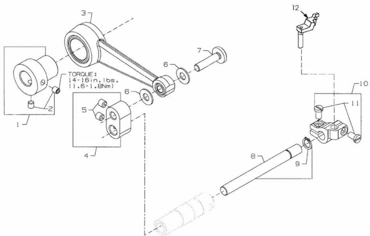
text_image
TORQUE: 14-16in. lbs. (1.6-1.8Nm) 1 2 3 4 5 6 7 8 9 10 11 12NEEDLE GUARD
| Ref. | Amt. | ||
| No. | Part No. | Description | Req. |
- 50373DA Needle Guard Eccentric 1
- SS8110422TP Screw, for needle guard eccentric 1
- 50368W Connecting Rod Assembly, for needle guard 2
- 50668 Pivot Link 1
- SS8110422TP Screw 1
- 50368E Washer 2
- 50368A Pivot Pin 2
- 50622C Shaft, for needle guard 1
- RC0560711KP Retaining Ring 1
- 50625 Holder, for needle guard 1
- SS6090620SP Screw 2
- C50025E Needle Guard, Rear (32 Gauge/36 Gauge).... 1
text_image
Technical diagram of a mechanical assembly with numbered components for identification
text_image
25 27 26 28 24 30 29LOOPER THREAD TAKE-UP
Ref.
No. Part No.
Description
Amt.
Req.
- 50657A Cast-Off Plate Assembly 1
- SD0380551SL Screw 1
- 50332AC Tension Spring 1
- 50347R Pin....1
- 51959B Tension Disc 2
- 50358H Eyelet 3
- SS7060310SP Screw 3
- SS6060440TP Screw 1
- 41358 Washer 2
- SS9080410SP Screw 1
- 50304H Strike-Off Wire 1
- 50604 Retaining Finger 1
- SS7080520SP Screw 2
- 50383E Mounting Bracket 1
- 50357AN Cast-Off Plate 1
- SS9111010SP Screw, for collar bracket 1
- SS6110610TP Screw, for cast-off holder 1
- 29476UK Cast-Off Plate Holder Assembly 1
- SS7092110TP Screw, for collar bracket 1
- 50383F Take-up Collar Bracket 1
- 50304K Cast-Off Plate Holder 1
- WZ0640200KP Washer 1
- SD0630275SP Shoulder Screw, for cast-off plate holder 1
- 50623B Take-up Assembly 1
- 22894C Set Screw 2
- 50323B Take-up Hub 1
- 22-348 Pin.... 2
- C50077P Spacer 1
- 50323L Disc, for take-up 2
- 77B Screw, for take-up disc 2
text_image
TORQUE: 32-34 in. lbs. (3.6-3.9Nm)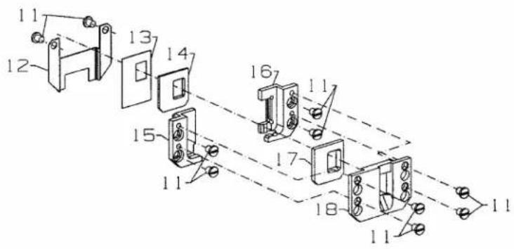
text_image
Technical diagram of a mechanical assembly with numbered components, likely for assembly or maintenance instructions.FEED DRIVE MECHANISM
FOR PLAIN FEED
Ref.
No. Part No.
Description
Amt.
Req.
- 18-1432 Screw 1
- 50334BD Hex Eccentric Stud 1
- 29126FB Drive Fork Assembly, right 1
- 50634 Feed Bar Assembly 1
- 50334A Plain Feed Bar Guide 1
- 50634E Feed Dog Holder 1
- 22637P24 Screw 1
- SS7091110TP Screw 1
- 50640-29 Feed Eccentric, main 1
- SS8660612TP Screw 2
- SS7090530SP Screw 10
- 50334Y Oil Shield 1
- 50334W Oil Scraper 1
- 50634C Feed Bar Seal 1
- 50637A Guide Plate, left, rear 1
- 50335BA Guide Plate, right, rear 1
- 50634D Feed Bar Seal 1
- 50637 Guide Plate, front 1

text_image
TORQUE: 32-34 in. lbs. (3.6-3.9Nm) TORQUE: 32-34 in. lbs. (3.6-3.9Nm)FEED DRIVE MECHANISM
FOR DIFFERENTIAL FEED
Ref.
No. Part No.
Description
Amt.
Req.
- 18-1432 Screw 2
- 50334BD Hex Eccentric Stud 2
- 29476VV Drive Fork Assembly 1
- 50334AW Drive Fork Assembly 1
- 50340F Feed Eccentric, differential 1
- SS8660612TP Screw 2
- 50334BE Feed Bar Assembly 1
- 50334AX Drive Fork Assembly, right 1
- 50640A29 Feed Eccentric, main 1
- SS8660612TP Screw 2
- SS7090530SP Screw 10
- 50334Y Oil Shield 1
- 50334V Oil Scraper 1
- 50334BH Feed Bar Seal 1
- 50335AM Guide Plate, left, rear 1
- 50335BA Guide Plate, right, rear 1
- 50334BJ Feed Bar Seal 1
- 50335AN Guide Plate, front 1
- 660-220 "O" Ring 1
- 50337J Stem, for differential feed lever 1
- SS4121215SP Screw, for stem 1
- 29476YH Differential Feed Lever Assembly 1
- 50337H Differential Feed Lever 1
- 50337U Stop 2
- 50337BD Plate, for differential feed lever 1
- SS7090610SP Screw 2
- B1647704000A Knob, for differential feed lever 1
- 50387 Screw 1
- SS7090610SP Screw 2
- 50337S Collar 1
- SS8110422TP Screw 2
- 50337L Coupling, for differential feed lever 1
- SS6110650TP Screw 2
- 50337R Collar, for differential feed lever 1
- SS8090710SP Screw 1
- SS6091022TP Screw 1
- SP0550271TP Screw, for spring 1
- 50337M Spring, for differential feed lever 1

text_image
Technical diagram of a mechanical assembly with numbered components and exploded viewsFEED DRIVE MECHANISM
FOR PLAIN FEED
Ref.
No. Part No.
Description
Amt.
Req.
- TA075404RO Plug, for eccentric shaft 1
- 22591A Screw, for eccentric shaft 1
- 50334BC Eccentric Shaft 1
- 50674 Washer, for eccentric shaft 1
- 50334BB Collar, forecentric shaft 1
- SS8110422TP Screw, for collar 2
- 50337T Collar, for eccentric shaft 1
- SS8110422TP Screw, for collar 2
- 661-96 Spring Washer 1
- 660-969 "O" Ring, for bushing 1
- SS8661012TP Screw, for bushing 1
- 35036F Bushing, for stitch adjusting shaft 1
- 660-220 "O" Ring, for stitch adjusting shaft 1
- 35036AZ Brake Pad 1
- 50634G Stitch Adjusting Shaft Assembly 1
- 50335D Collar 1
- 22894P Screw 2
- 50333S Collar 1
- 22894P Screw 2
- 29476UF Stitch Length Adjusting Rod Assembly 1
- 660-980 "O" Ring, stitch control shaft 1
- 50322AR Shaft, for stitch control 1
- 660-206 "O" Ring, for stitch control shaft 1
- 50336Y Stitch Knob, indicator 1
- SS8110422TP Screw 1
- 50335 Spring Retainer 1
- 22714C Screw, for spring retainer 1
- 50355 Spring 1
- 50335A Spring Holder 1
- 50336S Stitch Control Lever 1
- 661-35 Pin.... 1
- 22596H Screw 2

text_image
Technical diagram of a mechanical assembly with numbered components and exploded viewsFEED DRIVE MECHANISM
FOR DIFFERENTIAL FEED
Ref.
No. Part No.
Description
Amt.
Req.
- 22591A Screw, for eccentric shaft 1
- 50334BC Eccentric Shaft 1
- 50368AD Washer, foreccentric shaft 1
- 50334BB Collar, for eccentric shaft 1
- SS8110422TP Screw, for collar 2
- 50337T Collar, for eccentric shaft 1
- SS8110422TP Screw, for collar 2
- 661-96 Spring Washer 1
- 660-969 "O" Ring, for bushing 1
- SS8661012TP Screw, for bushing 2
- 35036F Bushing, for stitch adjusting shaft 2
- 660-220 "O" Ring, for stitch adjusting shaft 1
- 35036AZ Brake Pad 2
- 50634G Stitch Adjusting Shaft Assembly 2
- 50335D Collar 1
- 22894P Screw 2
- 50333S Collar 1
- 22894P Screw 2
- 29476UF Stitch Length Adjusting Rod Assembly 1
- 660-980 "O" Ring, stitch control shaft 1
- 50322AR Shaft, for stitch control 1
- 660-206 "O" Ring, for stitch control shaft 1
- 50336Y Stitch Knob, indicator 1
- SS8110422TP Screw 1
- 50335 Spring Retainer 1
- 22714C Screw, for spring retainer 1
- 50355 Spring 1
- 50335A Spring Holder 1
- 50336S Stitch Control Lever 1
- 661-35 Pin 1
- 22596H Screw 2
text_image
Three Bond: Union Special No. CE63 (top & bottom screws only)COVERS, LOWER BED
| Ref. | Amt. | ||
| No. | Part No. | Description | Req. |
- 18-1448 Screw 11
- 50601F Cloth Plate, left 1
- 50601E Cloth Plate, right.... 1
- 50303B Acoustic Pad 1
- SS6121212TP Screw, for cover 6
- 50382CP Cover, for feed chamber 1
- 50382CS Gasket 1
- SS7150740SP Screw 2
- 22587N Screw 2
- 35036AE Ferrule, Locating 2
- 50380D Throat Plate Support, complete 1
- 51280K Pin 1
- 660-939 Rubber Bumper, for Throat Plate Support 1
- C067D Cork 2
- 22517 Screw, for bed 2
- 50382CR Gasket 1
- 50382CL Cover, rear, for feed chamber, 1
- SS4120615SP Screw, for cover 2
- CE63 Three Bond Adhesive, (not shown), for screw -
text_image
Technical diagram of a mechanical assembly with numbered components and exploded viewsCOVERS, LOWER BED
| Ref. | Amt. | ||
| No. | Part No. | Description | Req. |
- 50393HB Plug, for bed 2
- 50684A Gasket, for left end cover 1
2A. 50382CM Quad Ring, for left end cover 1 - 50682B Left End Cover 1
3A. 50382KE Left End Cover 1 - SS4151415SP Screw 4
- 50393HA Plug 1
- WO3 Oil Wick, for needle guard 1
- 22841U Machine Support Stud 4
- 50383G Gasket, for chamber cover 1
- 50382CG Dry Chamber Cover 1
- SS7090850SP Screw 8
- 50378S Hinge 2
- SS9110543CP Screw 4
- 660-1020 Rubber Bumper 2
- SS6120930TP Screw 4
- 20 Washer 2
- 50382T Stop, for front cover 2
- 50393W Rubber Bumper 2
- 22519J Screw 2
- 50682D Swing Down Cover 1
- 22729D Screw 2
- 50667 Lever 1
- SS4121015SP Screw 4
- 50393HU Plug, right end, non-synchronizer 1
- 50382CJ Cover, for drive belt 1
- 50332A Latch Spring 2
- 39250J Nut 2
- 22513D Screw 2
- 50382FP Latch, looper throw-out safety 1
- 25CC Screw 2
- 35569J Nut 1
- 50332B Support Block 1
- SS7120710SP Screw 2
- 22799AH Spring Latch Stud 2
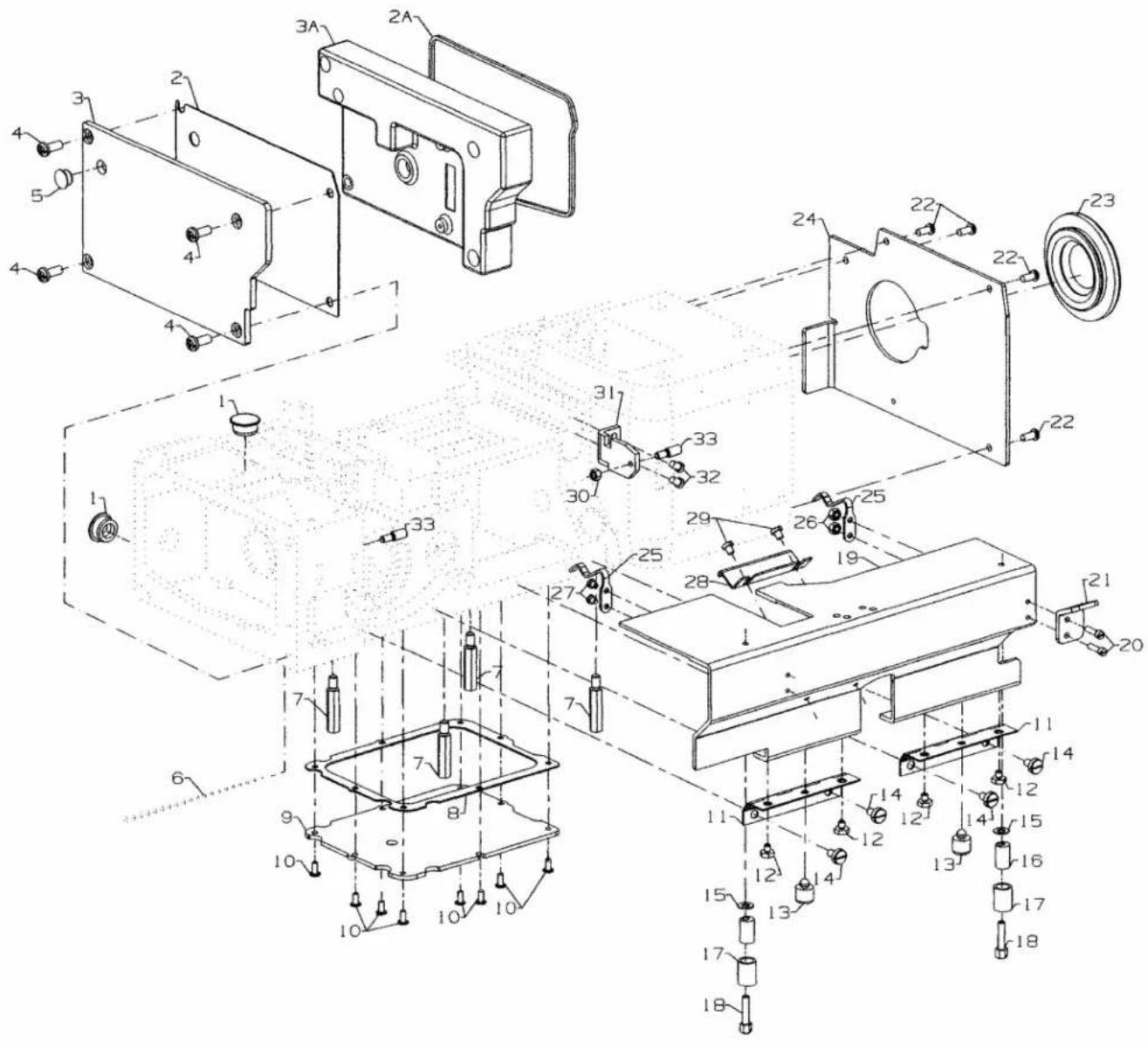
text_image
Technical diagram of a mechanical assembly with numbered parts, likely an electrical or mechanical component, showing exploded and assembled views.| LEDOM | D | TOOFRESSERPYLBMESSA | A | ETALPTAORHT | E | DOG | G | DEEFLAITNEREFFID | H | |
| 1AP2CC2 | 3H5-36L513SF | 605 | B | 2 | 51605D50605 | 3 | 2 R | |||
| FS315L63-3H36CC2PA1 | 50618C | 50620A36 | 50624R36 | 5D | ||||||
| FS316L61-3H32CC2PA1 | 50618B | 50620A32 | 50624A32 | 06096 | ---- | |||||
| FS316L61-3H32CC2PA1 | 50618C | 50620A36 | 50624A36 | |||||||
| FS316L62-3H32CC2PA1 | 50618B | 50620A32 | 50624B32 | B50606 | ---- | |||||
| FS318L62-3H3 1AP2CC6 | 50618C | 50620A36 | 50624B36 | |||||||
| FS316L63-3H32CC2PA1 | 50618B | 50620-32 | 50624H32 | 63R50608 | ---- | |||||
| 1AP2CC6 | 3H5-36L610961 | 50620-36 | C | 50624R36 | ||||||
0 3
SEWING PARTS
-
-
-
-
-
- Presser Foot Assembly, (see Chart) 1
-
-
-
-
-
50630C Presser Foot Fork 1
-
SS7120910TP Screw 1
-
22845A Screw 2
-
22599 Screw 1
-
35830K Spring 1
-
35830R8 Presser Foot Bottom, for style FS316L61-3H32CC2PA1 1
- 35830R9 Presser Foot Bottom, for style FS316L61-3H36CC2PA1 1
- 50630B32 Presser Foot Bottom, for style FS316L62-3H32CC2PA1 1
- 50630B36 Presser Foot Bottom, for style FS316L62-3H36CC2PA1 1
- 50630A Presser Foot Bottom, for style FS316L63-3H32CC2PA1 1
- 50630 Presser Foot Bottom, for style FS316L63-3H36CC2PA1 1
-
50605D Feed Dog,(see chart) FS315L63-3H32CC2PA1, FS315L63-3H36CC2PA1..... 1
-
50626D Feed Dog,(see chart) FS315L63-3H32CC2PA1, FS315L63-3H36CC2PA1..... 1
-
SS7091110TP Screw 2
-
Feed Dog,(see chart) FS316L61-3H32CC2PA1, FS316L61-3H36CC2PA1..... 1
-
-
-
-
-
- Feed Dog,(see chart) FS316L62-3H32CC2PA1, FS316L62-3H36CC2PA1 .. 1
-
-
-
-
-
-
-
-
-
- Feed Dog,(see chart) FS316L63-3H32CC2PA1, FS316L63-3H36CC2PA1 .. 1
-
-
-
-
-
18-1481 Screw.... 1
-
---- Needle Head, (see chart) 1
-
SS8080310TP Screw 3
-
660-1046 Pin 3
-
50618D Needle Head Eyelet 1
- 50618A Needle Head Eyelet 1
-
22655B7 Screw 2
-
---- Throat Plate, for style FS316L61-3H32CC2PA1, FS316L61-3H36CC2PA1 .... 1
-
---- Throat Plate, for style FS316L62-3H32CC2PA1, FS316L62-3H36CC2PA1 .... 1
-
---- Throat Plate, for style FS316L63-3H32CC2PA1, FS316L63-3H36CC2PA1 .... 1
-
22570 Screw 2
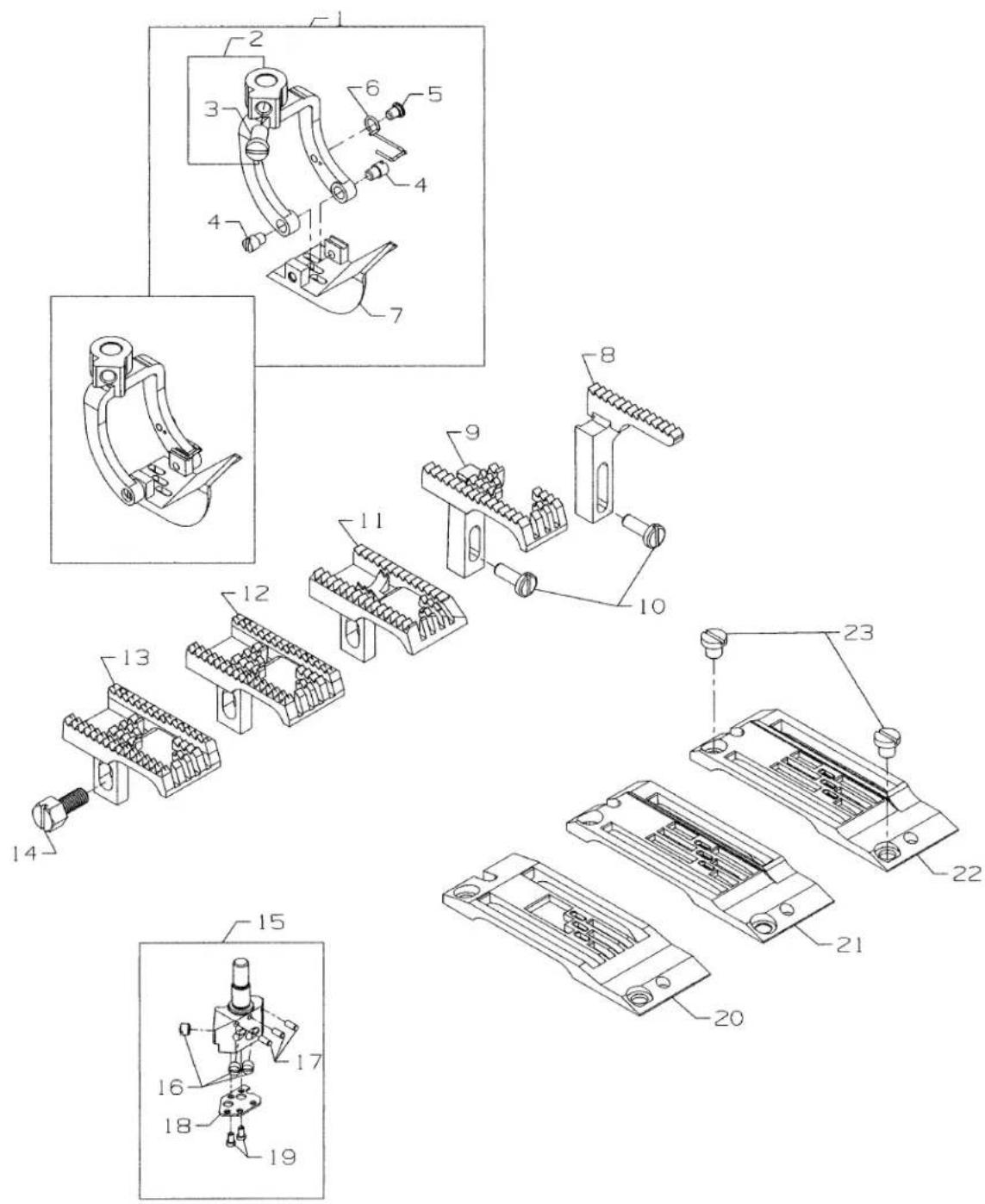
text_image
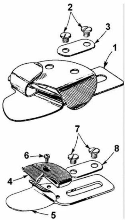
Technical diagram showing exploded and assembled views of a mechanical component with numbered partsFOLDERS
Ref.
No. Part No. Description
Amt.
Req.
- 23420S8-1/8 Folder, for Styles, FL53-3H32 1
- 23420S9-1/8 Folder, for Styles, FL53-3H36 1
- 23420U16-3/32 Folder, for Styles, FL52-3H64 1
- 25C Screw 2
- 57864B Clamp Plate 1
- 23421U16-3/32 Scroll, For Styles, FL52-3H32 1
- 23421U18-3/32 Scroll, For Styles, FL52-3H36, FL52-2H72 1
- 23422BZ-3/32 Scroll, Lower, For Styles, FL52-3H32, FL52-3H36 1
- 23422U-3/32 Scroll, Lower, For Styles, FL52-2H72 1
- 28 Screw 1
- 25C Screw 2
- 57864B Clamp Plate 1
text_image
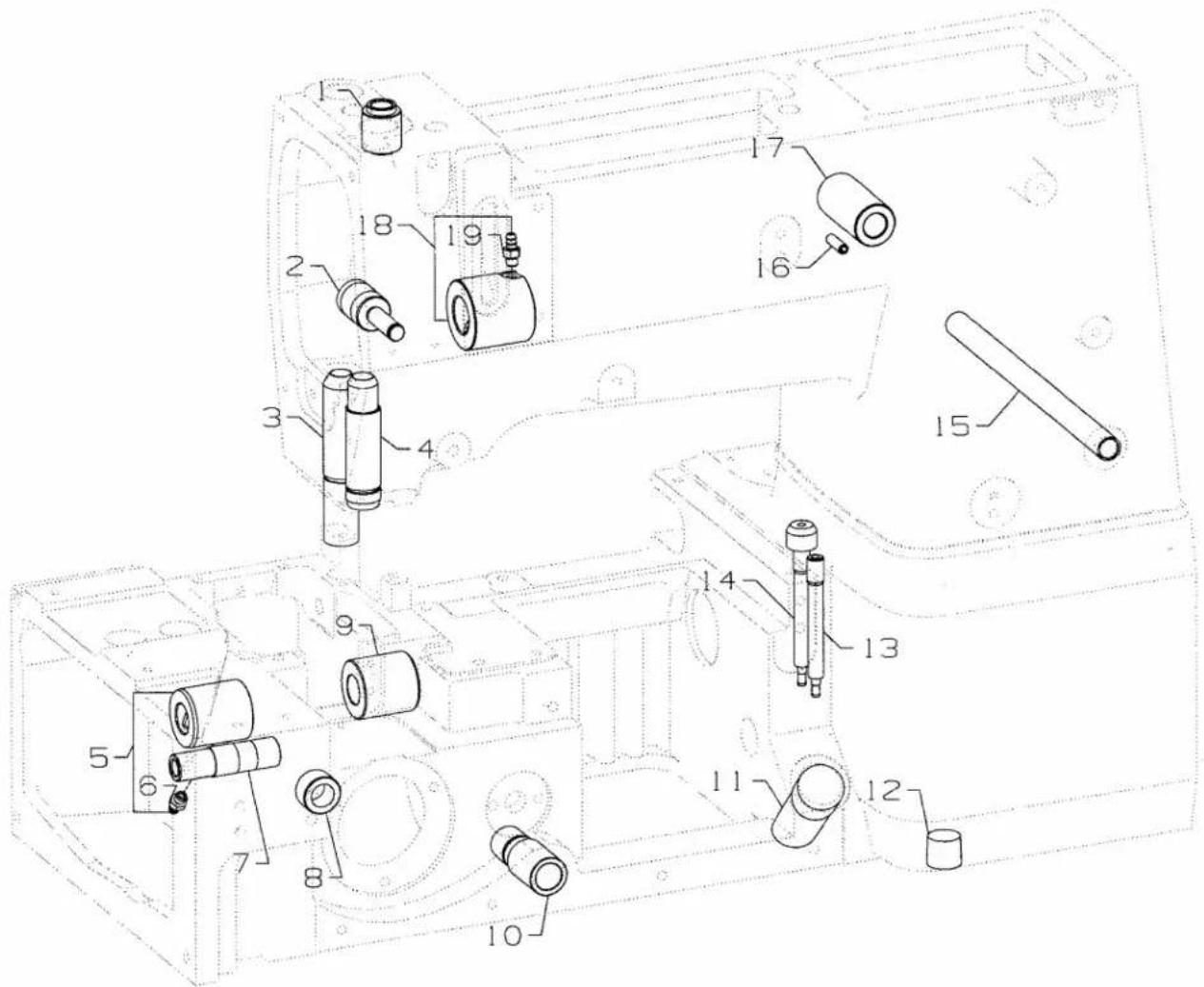
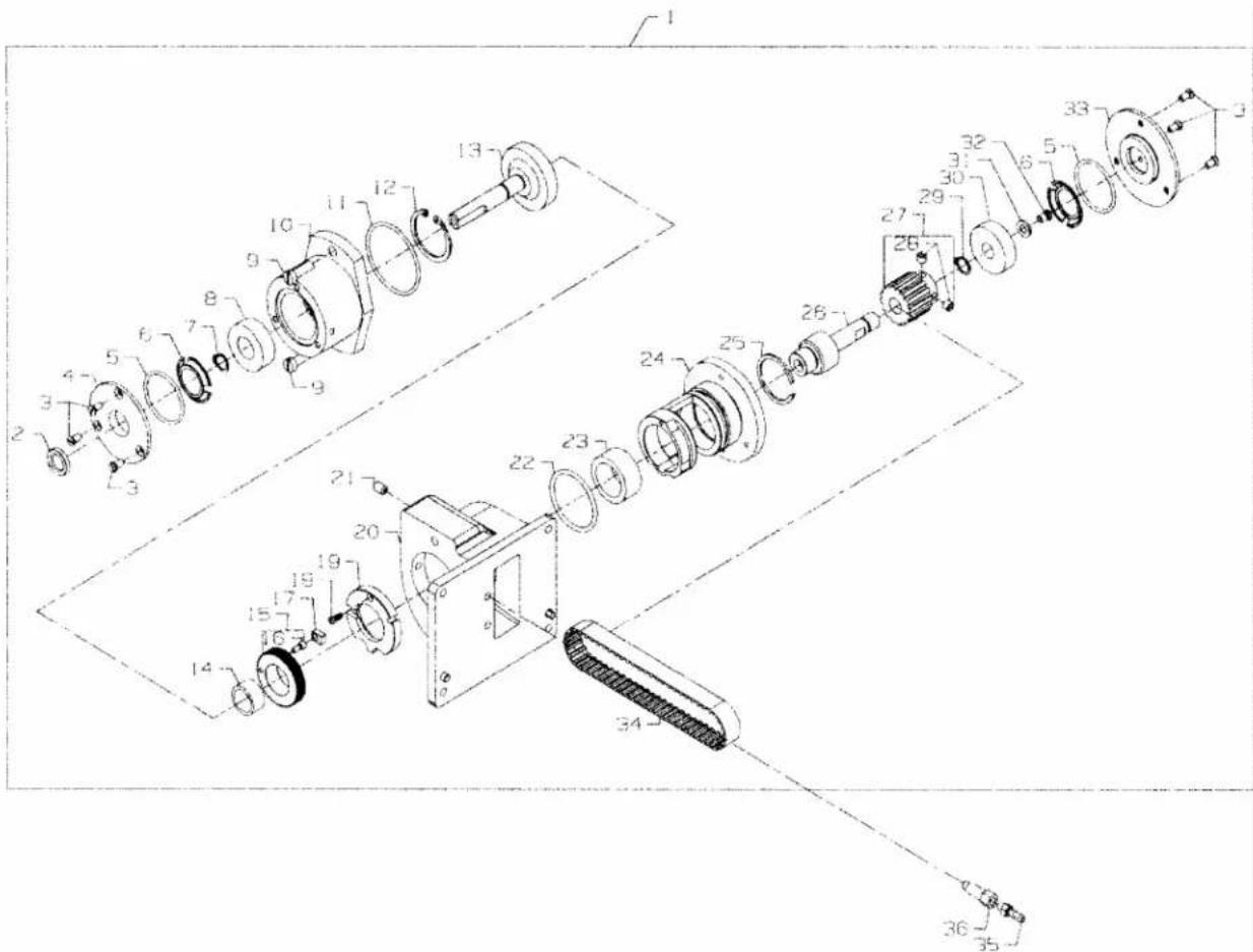
Technical diagram of an electric motor assembly with numbered components for identificationPULLER DRIVE ASSEMBLY
Ref.
No. Part No.
Description
Amt.
Req.
-
29476YG Puller Drive Assembly 1
-
660-893 Lip Seal 1
-
22524 Screw 6
-
C50082AP Cover 1
-
660-886A "O" Ring 2
-
660-914 Finger Spring 2
-
660-918 Retaining Ring 1
-
660-890 Bearing 1
-
136 Screw 2
-
50677A Bearing Housing 1
-
660-886B "O" Ring 1
-
660-891B Snap Ring 1
-
50677U Internal Gear 1
-
660-889 Bearing 1
-
C50078M Internal Gear 1
-
C50078K Pin 1
-
C50078J Slide Block 1
-
22593 Screw 1
-
C50078N Guide Ring 1
-
50677 Puller Drive Housing 1
-
22894J Screw 1
-
660-886C "O" Ring 1
-
660-892C Bearing 1
-
C50078P Eccentric Housing 1
-
661-70A Snap Ring 1
-
C50022L Eccentric Drive Shaft 1
-
C50042AC16 Sprocket 1
-
98 Screw 2
-
660-891C Snap Ring 1
-
660-888 Bearing 1
-
59451F Washer 1
-
22574D Screw 1
-
C50082AR Cover 1
-
C50042AF Timing Belt 1
-
671F19 Barb Fitting 1
-
671F64 Extension Fitting 1

text_image
Technical diagram of a mechanical assembly with numbered components and exploded viewsPULLER ASSEMBLY
Ref.
No. Part No.
Description
Amt.
Req.
-
29476YB Puller Assembly 1
-
C50077D Screw, Adjusting 1
-
50677N Bracket, Main Puller 1
-
WZ0850302K0 Washer 1
-
50677G Lever, Lifter 1
-
RM3211-12 Nut 1
-
50667A Knob, Ball 1
-
50677C Lever, Lifter 1
-
50695A Stud Screw 1
-
50677E Lever, Roll Pressure 1
-
SS9110430TP Screw 1
-
SS9121210TP Screw 1
-
B4107850M00 Pin 1
-
50677L Feed Roller 1
- 50677M Feed Roller, Urethane 1
- 50677R Feed Roller, Knurled 1
- 50677K Feed Roller, Reversed Teeth 1
-
SS8090540SP Screw 2
-
50677F Shaft, Feed Roller 1
-
C50042AD Belt 1
-
50677H Yoke, Feed Roller 1
-
SS6080810SP Screw 1
-
50635 Link, Connection 1
-
604 Screw 1
-
39656A Knife 1
-
SS6121610SP Screw 1
-
50677S Washer 2
-
50638 Block, Mounting 1
-
660-887 Bearing 1
-
50677T Shaft, Feed Roller 1
-
50642D Sprocket, Feed Roller 1
-
SS8090540SP Screw 2
-
WP0531000SD Washer 2
-
SS6122030SP Screw 2
-
50633A Block, Adjustable 1
-
11846805 Pin.... 1
-
SS9151440CP Screw 1
-
50633 Collar, Puller Lifter 1
-
50647 Pin....1
-
SS8150822TP Screw 1
-
22726Z Screw 1
-
NS6150310SP Nut 1
-
50677B Shaft, Puller Lifter 1
-
28633L Spring 1
-
51242L Washer 1
-
50662B Adaptor Plate 1
-
SS7120910SP Screw 2
text_image
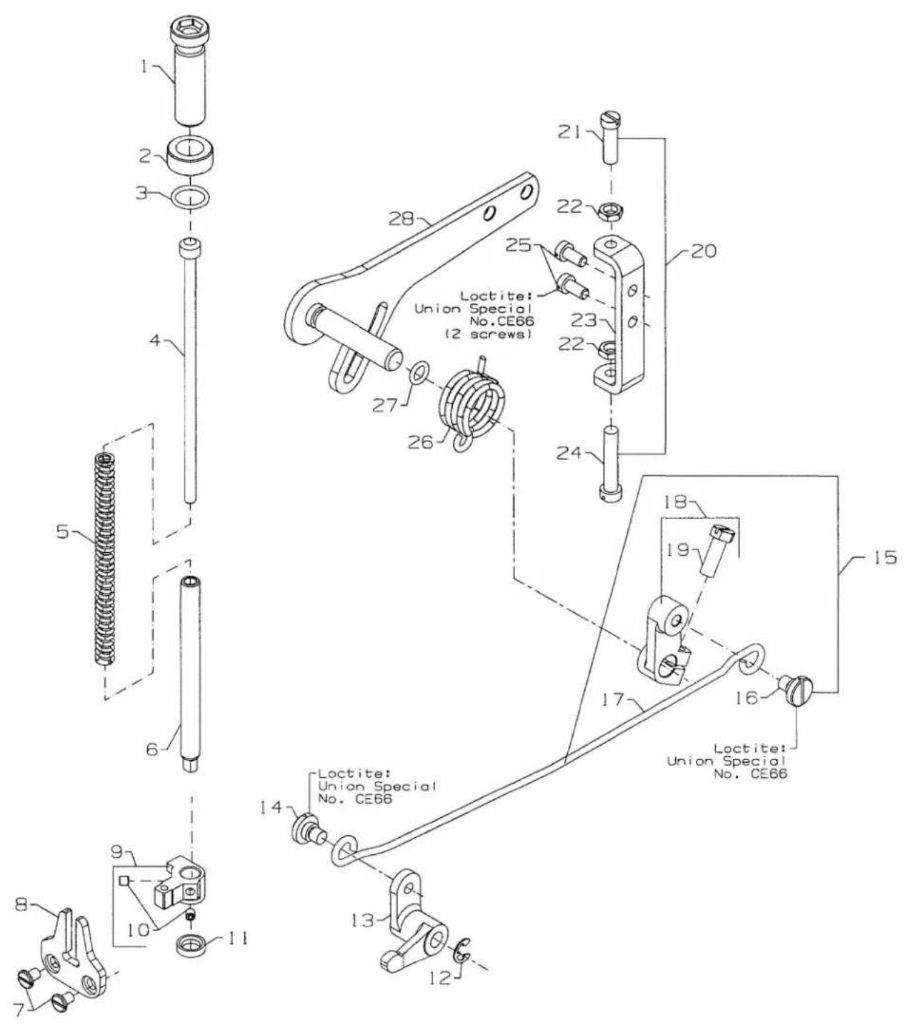
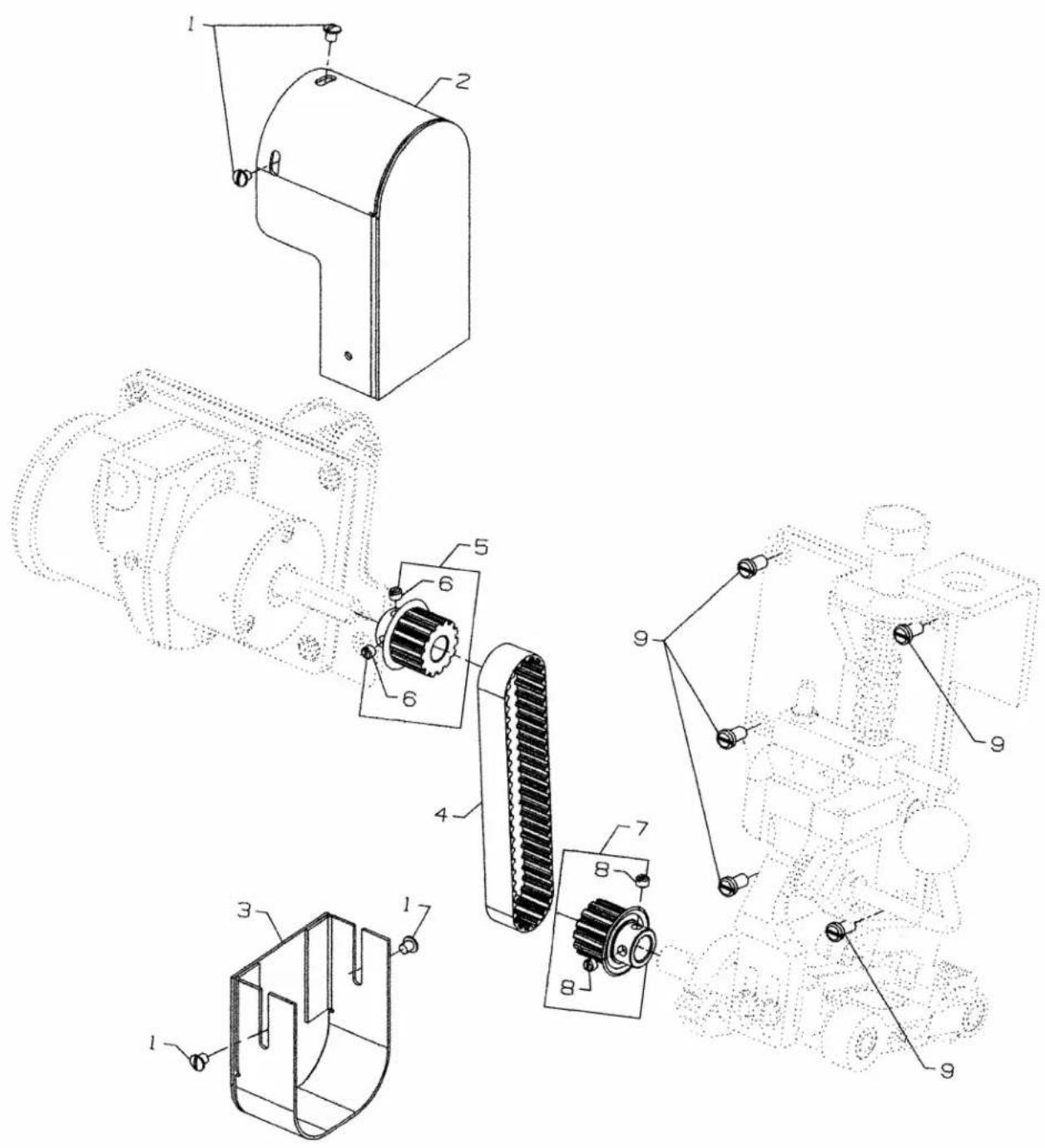
Technical diagram of a mechanical assembly with numbered components for identificationPULLER ASSEMBLY
| Ref. | Amt. | ||
| No. | Part No. | Description | Req. |
- 22825 Screw 4
- 50696C Belt Guard, Upper 1
- 50696D Belt Guard, Lower 1
- 50642B Belt 1
*5. C50042Z14 Sprocket, 14 Teeth 1
* - C50042Z13 Sprocket, 13 Teeth.... 1 - 88B Screw 2
*7. C50042Z15 Sprocket, 15 Teeth.... 1
* - C50042Z16 Sprocket, 16 Teeth.... 1 - 88B Screw 2
- 22569C Screw 5
* See puller sprocket combinations chart (page 21).
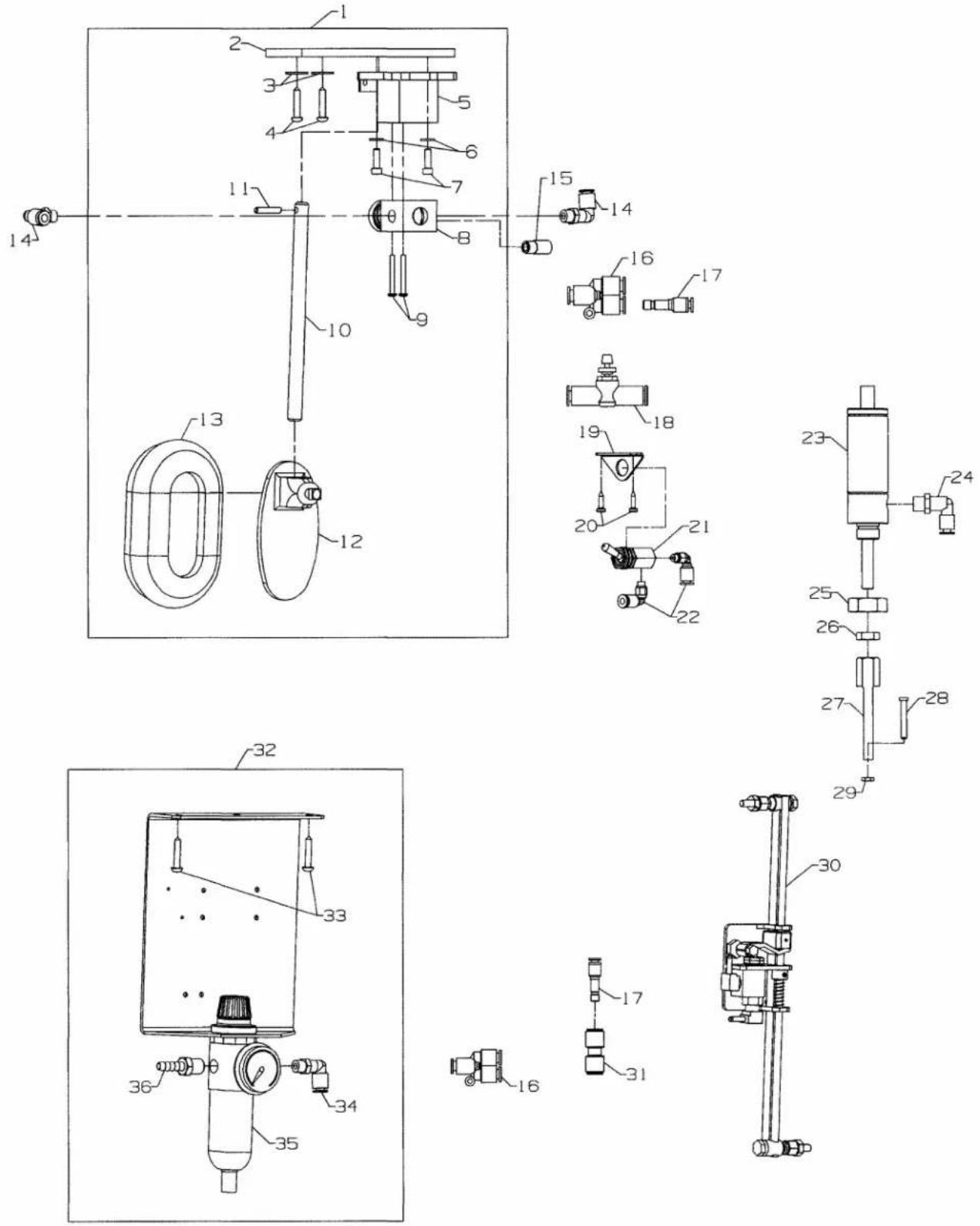
MISCELLANEOUS PARTS PA1 (USE WITH CC2 CHAIN CUTTER)
Ref.
No. Part No.
Description
Amt.
Req.
- 29480AWN Knee Press Fitting 1
- 50364H Mounting Plate 1
- 96902 Washer 2
- 90561K Wood Screw 2
- AS7-2 Knee Press Base 1
- RM3293-5 Flat Washer 2
- 22653B10 Screw 2
- 671-85 3-Way Valve Assembly 1
- RM4377-4 Screw 2
- AS7-1 Knee Press Rod 1
- 667C16 Dowel Pin.... 1
- AS7-3 Knee Press 1
- 660-168 Knee Press Pad 1
- 671F82H Elbow Fitting 2
- 660-403 Muffler.... 1
- 671F86B Hose "Y" Connector 2
- 671F82H 5/32"To 1/4" T Reducer 2
- 671-196 Flow Control 1
- 999-160 Bracket 1
- 90561E Wood Screw 2
- 671-66 Toggle Valve 1
- 671F82F Male Elbow 2
- 660-397 Air Cylinder 1
- 671F82C Male Elbow 2
- 99327 Nut 1
- 21233FB Nut 1
- 99590Q Cylinder Rod 1
- 99372B Screw 1
- 41071G Nut 1
text_image
Technical schematic diagram of a mechanical device with numbered components and exploded viewsMISCELLANEOUS PARTS PA1A (USE WITHOUT CC2 CHAIN CUTTER)
Ref.
No. Part No.
Description
Amt.
Req.
-
29480AWN Knee Press Fitting 1
-
50364H Mounting Plate 1
-
96902 Washer 2
-
90561K Wood Screw 2
-
AS7-2 Knee Press Base 1
-
RM3293-5 Flat Washer 2
-
22653B10 Screw 2
-
671-85 3-Way Valve Assembly 1
-
RM4377-4 Screw 2
-
AS7-1 Knee Press Rod 1
-
667C16 Dowel Pin.... 1
-
AS7-3 Knee Press 1
-
660-168 Knee Press Pad 1
-
671F82H Elbow Fitting 2
-
660-403 Muffler.... 1
-
671F86B Hose "Y" Connector 2
-
671F82H 5/32"To 1/4" T Reducer 2
-
671-196 Flow Control 1
-
999-160 Bracket 1
-
90561E Wood Screw 2
-
671-66 Toggle Valve 1
-
671F82F Male Elbow 2
-
660-397 Air Cylinder 1
-
671F82C Male Elbow 2
-
99327 Nut 1
-
21233FB Nut 1
-
99590Q Cylinder Rod 1
-
99372B Screw 1
-
41071G Nut 1
-
29480ARN Treadle Assembly 1
-
671F86D Fitting 1
-
29480ASU Filter Regulator Gauge Kit 1
-
90561K Wood Screw 2
-
671F81A Elbow Fitting 1
-
671D42 Combination Filter Regulator 1
-
671F88 Barb Fitting 1
TUBING PA1 WITH CHAIN CUTTER

text_image
To Puller Lift Cylinder A To Presser Foot Lift Cylinder Remove Plug & Add-Elbow 671FBIC A To Needle Cooler USE IN CONJUNCTION WITH CATALOG PT9623TUBING PA1A
WITHOUT CHAIN CUTTER
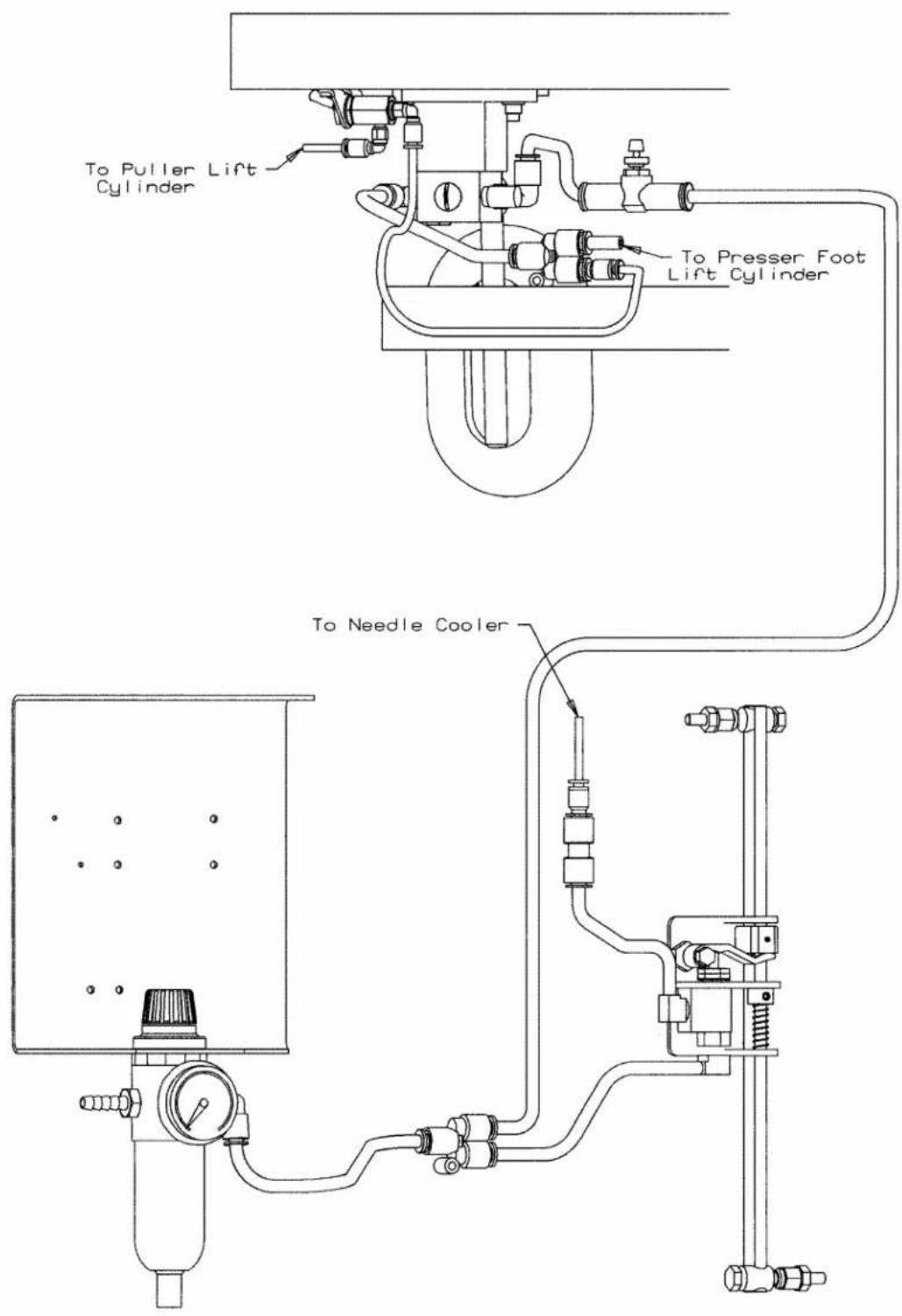
text_image
To Puller Lift Cylinder To Presser Foot Lift Cylinder To Needle Cooler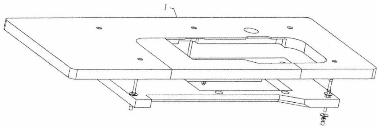
natural_image
Technical line drawing of a mechanical assembly with mounting base and internal cavity (no text or symbols)TABLING
(EXTRA SEND CHARGE)
Ref.
No. Part No.
Description
Amt.
Req.
- 21317AAH48 Table Board, for plain feed machines .... 1

text_image
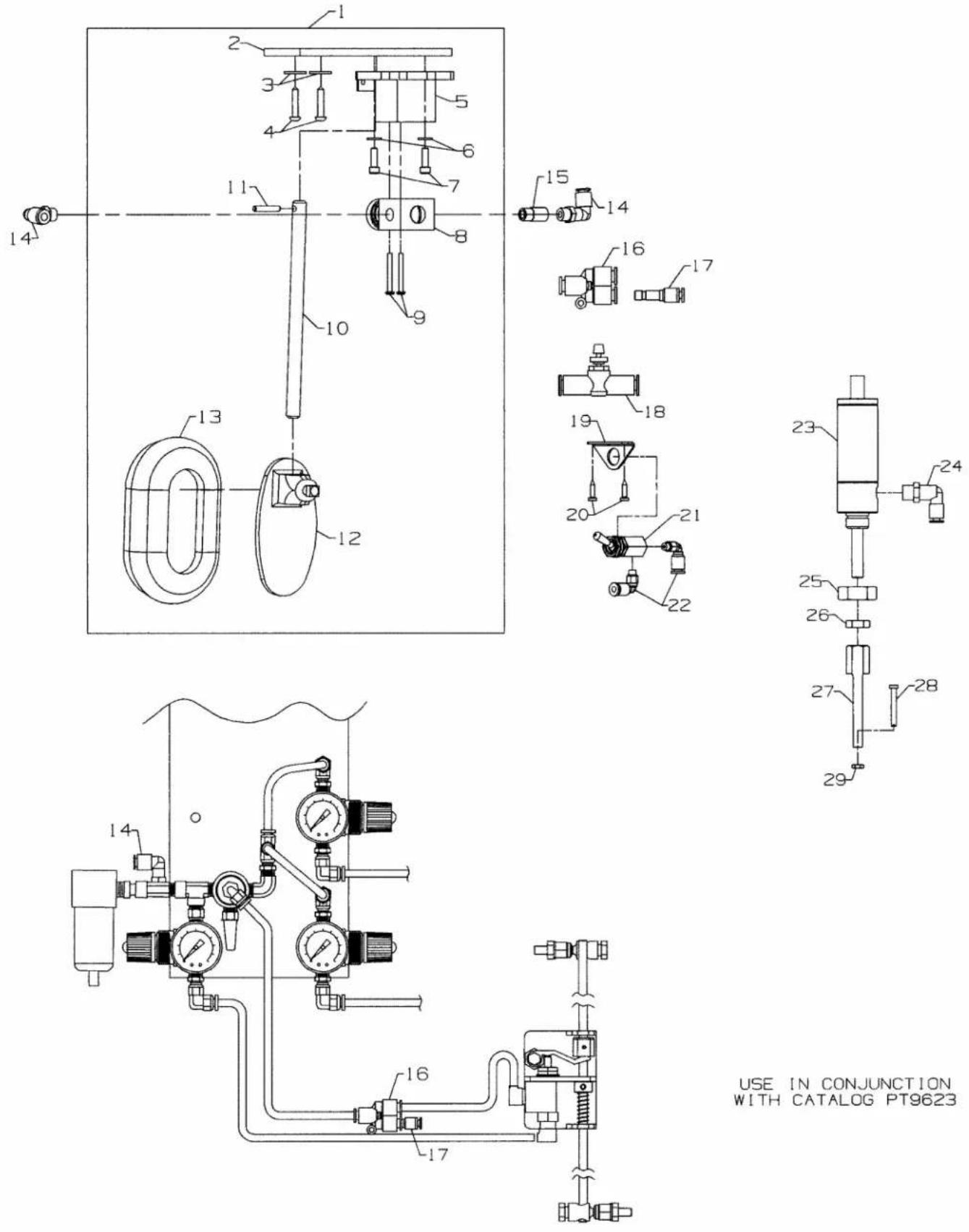
Technical diagram of a mechanical assembly with numbered components, likely a valve or pump assembly.PRESSER FOOT LIFTER
| Ref. | Amt. | ||
| No. | Part No. | Description | Req. |
- SS6122030SP Screw 1
- 50383AR Cylinder Support Bracket 1
- NS6120310SP Nut 1
- WS0510002KP Washer 1
- SS4121015SP Screw 1
- 50374K Spacer 1
- 29480AXJ Presser Foot Lifter Assembly 1
- 671A360 Air Cylinder 1
- 671F81C Fitting 1
- 50383AF Bracket 1
- 660-1099 Air Cylinder Cap 1
- SS4121215SP Screw 2
text_image
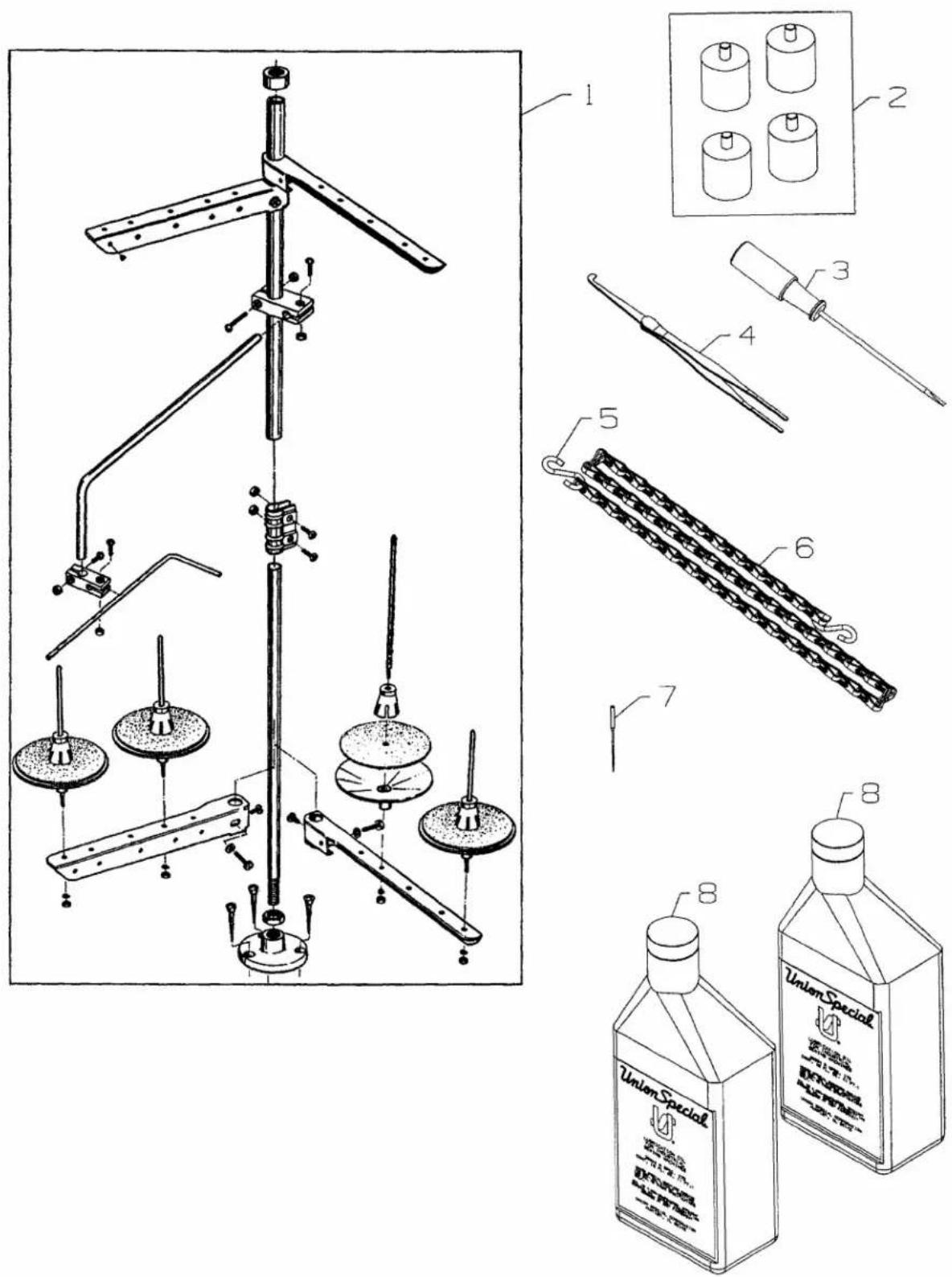
Technical diagram of a mechanical device with labeled components and parts, including a multi-tiered assembly and two labeled bottles.ACCESSORIES
| Ref. | Amt. | ||
| No. | Part No. | Description | Req. |
- 21101W4 Thread Stand (2 Needle) 1
- 21101W6 Thread Stand (3 Needle) 1
- 35095B Isolator 4
- 21201A Screw Driver, for needle head 1
- 660-240 Thread Tweezer 1
- 660-264 S-Hook 2
- 421D34 Chain.... 1
- 128GAS140/054 Needles 10
- 28604R Oil, (1 pint) 2
NUMERICAL INDEX OF PARTS
| Part No. | Page No. | Part No. | Page No. | Part No. | Page No. | Part No. | Page No. | Part No. | Page No. |
| 11071602 | 33 | 23421U16-3/32 | 61 | 50330CZ | 23 | 50354F | 25 | 50393-140 | 39 |
| 11071701 | 33 | 23421U18-3/32 | 61 | 50332A | 57 | 50355 | 51, 53 | 50393-170 | 39 |
| 11550100 | 31 | 23422BZ-3/32 | 61 | 50332AC | 45 | 50355AM | 25 | 50393-27 | 39 |
| 11843208 | 39 | 23422U-3/32 | 61 | 50332B | 57 | 50355AN | 25 | 50393-40 | 39 |
| 11846805 | 65 | 25C | 61 | 50332S | 39 | 50355AR | 33 | 50393-407 | 39 |
| 128GAS140/054 | 79 | 25CC | 57 | 50332U | 23 | 50357AE | 29 | 50393-47 | 39 |
| 136 | 63 | 28 | 61 | 50332V | 33 | 50357AN | 45 | 50393-51 | 39 |
| 13765607 | 39 | 28604R | 79 | 50333A | 37 | 50357AS | 29 | 50393-70 | 39 |
| 18-1432 | 47, 49 | 28633L | 65 | 50333S | 51, 53 | 50357V | 29 | 50393-89 | 39 |
| 18-1448 | 55 | 29126FB | 47 | 50334A | 47 | 50357Y | 29 | 50393EB | 39 |
| 18-1481 | 59 | 29476TC | 25 | 50334AW | 49 | 50358H | 45 | 50393EU | 35 |
| 20 | 57 | 29476TT | 33 | 50334AX | 49 | 50358V | 29 | 50393EW | 35 |
| 21101W4 | 79 | 29476UF | 51, 53 | 50334BB | 51, 53 | 50358W | 29 | 50393EX | 39 |
| 21101W6 | 79 | 29476UH | 37 | 50334BC | 51, 53 | 50358X | 25 | 50393EY | 23 |
| 21201A | 79 | 29476UK | 45 | 50334BD | 47, 49 | 50364H | 69, 71 | 50393FR | 39 |
| 21233FB | 69, 71 | 29476UT | 39 | 50334BE | 49 | 50366 | 29 | 50393FS | 39 |
| 21237DR | 35 | 29476VN | 25 | 50334BH | 49 | 50366B | 29 | 50393FT | 39 |
| 21237ET | 35 | 29476VV | 49 | 50334BJ | 49 | 50368A | 43 | 50393FU | 23 |
| 21237EU | 35 | 29476XV | 39 | 50334V | 49 | 50368AD | 53 | 50393FV | 39 |
| 21237EV | 35 | 29476YB | 65 | 50334W | 47 | 50368E | 43 | 50393GB | 39 |
| 21317AAH48 | 75 | 29476YD | 33 | 50334Y | 47, 49 | 50368W | 43 | 50393GD | 39 |
| 22-348 | 45 | 29476YG | 63 | 50335 | 51, 53 | 50370F | 29 | 50393GE | 23 |
| 22513D | 57 | 29476YH | 49 | 50335A | 51, 53 | 50373DA | 43 | 50393HA | 57 |
| 22517 | 55 | 29480ARN | 71 | 50335AG | 33 | 50374 | 37 | 50393HB | 35, 57 |
| 22517B | 35 | 29480ASU | 71 | 50335AH | 33 | 50374K | 77 | 50393HH | 29 |
| 22519J | 57 | 29480AWN | 69, 71 | 50335AK | 37 | 50378S | 57 | 50393HJ | 39 |
| 22524 | 63 | 29480AXJ | 77 | 50335AM | 49 | 50380D | 55 | 50393HK | 39 |
| 22565 | 41 | 34393D | 39 | 50335AN | 49 | 50381 | 33 | 50393HL | 39 |
| 22569B | 35 | 35036AE | 55 | 50335BA | 47, 49 | 50381B | 33 | 50393HN | 39 |
| 22569C | 67 | 35036AZ | 51, 53 | 50335BB | 37 | 50381E | 23 | 50393HR | 39 |
| 22570 | 59 | 35036BS | 23 | 50335BD | 27 | 50381F | 33 | 50393HU | 57 |
| 22571E | 39 | 35036F | 51, 53 | 50335D | 51, 53 | 50381G | 33 | 50393JP | 25 |
| 22571L | 23 | 35095B | 79 | 50336S | 51, 53 | 50382CG | 57 | 50393JW | 25 |
| 22574D | 63 | 35569J | 57 | 50336Y | 51, 53 | 50382CJ | 57 | 50393JZ | 25 |
| 22587N | 55 | 35830K | 59 | 50337BD | 49 | 50382CL | 55 | 50393KF | 39 |
| 22591A | 51, 53 | 35830R8 | 59 | 50337H | 49 | 50382CM | 57 | 50393KH | 39 |
| 22593 | 63 | 35830R9 | 59 | 50337J | 49 | 50382CP | 55 | 50393KM | 39 |
| 22596H | 51, 53 | 36271A | 29 | 50337L | 49 | 50382CR | 55 | 50393W | 57 |
| 22599 | 59 | 39250J | 57 | 50337M | 49 | 50382CS | 55 | 50601E | 55 |
| 22637P24 | 47 | 39656A | 65 | 50337R | 49 | 50382FP | 57 | 50601F | 55 |
| 22652B10 | 41 | 41071G | 69, 71 | 50337S | 49 | 50382FW | 35 | 50604 | 45 |
| 22652J10 | 41 | 41358 | 45 | 50337T | 51, 53 | 50382FX | 35 | 50605D | 59 |
| 22653B10 | 69, 71 | 421D34 | 79 | 50337U | 49 | 50382FY | 35 | 50618A | 59 |
| 22653J8 | 41 | 50303B | 55 | 50338 | 25 | 50382FZ | 35 | 50618D | 59 |
| 22655B7 | 59 | 50304H | 45 | 50338A | 25 | 50382GA | 35 | 50622C | 43 |
| 22714C | 51, 53 | 50304K | 45 | 50340F | 49 | 50382GM | 35 | 50622D | 37 |
| 22726Z | 65 | 50313C | 41 | 50342AX | 37 | 50382KE | 57 | 50622E | 37 |
| 22729D | 57 | 50313J | 41 | 50342BE | 27 | 50382T | 57 | 50623B | 45 |
| 22784N | 35 | 50314E | 41 | 50342BJ | 41 | 50383AF | 77 | 50625 | 43 |
| 22799AH | 57 | 50314F | 41 | 50342BK | 41 | 50383AR | 77 | 50626D | 59 |
| 22825 | 67 | 50317B | 25 | 50342BP | 41 | 50383E | 45 | 50630 | 59 |
| 22841U | 57 | 50317C | 35 | 50342BS | 37 | 50383F | 45 | 50630A | 59 |
| 22845A | 59 | 50321F | 27 | 50344AM | 41 | 50383G | 57 | 50630C | 59 |
| 22875N | 31 | 50321G | 37 | 50344BC | 23 | 50384 | 39 | 50630B32 | 59 |
| 22881C | 41 | 50322AF | 27 | 50344BE | 23 | 50384A | 39 | 50630B36 | 59 |
| 22894C | 45 | 50322AG | 37 | 50344BF | 23 | 50387 | 49 | 50632A | 33 |
| 22894J | 63 | 50322AL | 37 | 50344BU | 23 | 50392AB | 23 | 50633 | 65 |
| 22894P | 51, 53 | 50322AR | 51, 53 | 50344E | 23 | 50392AV | 31 | 50633A | 65 |
| 22894T | 27 | 50322BC | 27 | 50345W | 25 | 50392BA | 29 | 50634 | 47 |
| 23420S8-1/8 | 61 | 50323B | 45 | 50347R | 45 | 50392BC | 31 | 50634C | 47 |
| 23420S9-1/8 | 61 | 50323L | 45 | 50351A | 25 | 50392V | 29 | 50634D | 47 |
| 23420U16-3/32 | 61 | 50323P | 25 | 50352 | 25 | 50392Z | 31 | 50634E | 47 |
Part No. Page No.
Part No. Page No.
Part No. Page No.
Part No. Page No.
Part No. Page No.
| 50634G | 51, 53 |
| 50635 | 65 |
| 50637 | 47 |
| 50637A | 47 |
| 50638 | 65 |
| 50640-29 | 47 |
| 50640A29 | 49 |
| 50642 | 41 |
| 50642A | 27 |
| 50642B | 67 |
| 50642D | 65 |
| 50643C | 33 |
| 50647 | 65 |
| 50654 | 23 |
| 50654A | 23 |
| 50657A | 45 |
| 50658A | 29 |
| 50658B | 29, 35 |
| 50662A | 35 |
| 50662B | 65 |
| 50663A | 29 |
| 50666 | 29 |
| 50666A | 29 |
| 50666C | 29 |
| 50667 | 57 |
| 50667A | 65 |
| 50668 | 43 |
| 50674 | 51 |
| 50677 | 63 |
| 50677A | 63 |
| 50677B | 65 |
| 50677C | 65 |
| 50677E | 65 |
| 50677F | 65 |
| 50677G | 65 |
| 50677H | 65 |
| 50677K | 65 |
| 50677L | 65 |
| 50677M | 65 |
| 50677N | 65 |
| 50677R | 65 |
| 50677S | 65 |
| 50677T | 65 |
| 50677U | 63 |
| 50682B | 57 |
| 50682D | 57 |
| 50683 | 29 |
| 50684A | 57 |
| 50684B | 35 |
| 50684C | 35 |
| 50691 | 27 |
| 50692 | 31 |
| 50692A | 31 |
| 50692D | 31 |
| 50692E | 29 |
| 50692J | 31 |
| 50695A | 65 |
| 50696C | 67 |
| 50696D | 67 |
| 51170D | 35 |
| 51242L | 65 |
| 51280K | 55 |
| 51908B8 | 41 |
| 51908B9 | 41 |
| 51909C | 41 |
| 51909D8 | 41 |
| 51909D9 | 41 |
| 51959B | 45 |
| 53634C | 41 |
| 538A | 41 |
| 56392G | 31 |
| 56392H | 31 |
| 56392M | 31 |
| 57864B | 61 |
| 57865 | 31 |
| 57892K | 31 |
| 59451F | 63 |
| 604 | 65 |
| 605A | 29 |
| 652C16 | 35 |
| 660-1014 | 33 |
| 660-1020 | 57 |
| 660-1043 | 27 |
| 660-1046 | 59 |
| 660-1062 | 37 |
| 660-1087 | 27 |
| 660-1099 | 77 |
| 660-168 | 69,71 |
| 660-206 | 51,53 |
| 660-212 | 35 |
| 660-220 | 49 |
| 660-220 | 51,53 |
| 660-240 | 79 |
| 660-264 | 79 |
| 660-283A | 31 |
| 660-397 | 69,71 |
| 660-403 | 69,71 |
| 660-455 | 41 |
| 660-739 | 33 |
| 660-886 | 35 |
| 660-886A | 63 |
| 660-886B | 63 |
| 660-886C | 63 |
| 660-887 | 65 |
| 660-888 | 63 |
| 660-889 | 63 |
| 660-890 | 63 |
| 660-891B | 63 |
| 660-891C | 63 |
| 660-892C | 63 |
| 660-893 | 41,63 |
| 660-914 | 63 |
| 660-918 | 63 |
| 660-934 | 37 |
| 660-939 | 55 |
| 660-969 | 51,53 |
| 660-979 | 41 |
| 660-980 | 51,53 |
| 661-259B | 25 |
| 661-261 | 27 |
| 661-262 | 27 |
| 661-35 | 51,53 |
| 661-70A | 63 |
| 661-96 | 51, 53 |
| 666-328 | 25 |
| 667C16 | 69, 71 |
| 667J33 | 41 |
| 671-102A | 35 |
| 671-196 | 69, 71 |
| 671-66 | 69, 71 |
| 671-85 | 69, 71 |
| 671A360 | 77 |
| 671D42 | 71 |
| 671F19 | 63 |
| 671F64 | 63 |
| 671F81A | 71 |
| 671F81C | 77 |
| 671F82C | 69, 71 |
| 671F82F | 69, 71 |
| 671F82H | 69, 71 |
| 671F86B | 69, 71 |
| 671F86D | 71 |
| 671F88 | 71 |
| 77B | 45 |
| 88B | 67 |
| 90561E | 69, 71 |
| 90561K | 69, 71 |
| 96902 | 69, 71 |
| 98 | 63 |
| 99327 | 69, 71 |
| 99372B | 69, 71 |
| 99590Q | 69, 71 |
| 99682XC | 35 |
| 99682XC1 | 35 |
| 99682XC2 | 35 |
| 99682XCA | 35 |
| 998-358F | 39 |
| 999-160 | 69, 71 |
| AS7-1 | 69, 71 |
| AS7-2 | 69, 71 |
| AS7-3 | 69, 71 |
| B1647704000A | 49 |
| B3103800400 | 31 |
| B3112704000 | 31 |
| B3120352000 | 31 |
| B3120704000 | 31 |
| B3126012000 | 31 |
| B3530555000 | 35 |
| B4107850M00 | 65 |
| C067D | 55 |
| C50022L | 63 |
| C50025E | 43 |
| C50041D | 41 |
| C50041E | 41 |
| C50041F | 41 |
| C50041G | 41 |
| C50041H | 41 |
| C50042AC16 | 63 |
| C50042AD | 65 |
| C50042AF | 63 |
| C50042Z13 | 67 |
| C50042Z14 | 67 |
| C50042Z15 | 67 |
| C50042Z16 | 67 |
| C50044E | 29 |
| C50056B | 33 |
| C50077D | 65 |
| C50077P | 45 |
| C50078J | 63 |
| C50078K | 63 |
| C50078M | 63 |
| C50078N | 63 |
| C50078P | 63 |
| C50082AP | 63 |
| C50082AR | 63 |
| CE27 | 25 |
| CE49 | 33 |
| CE59 | 25 |
| CE63 | 25, 41, 55 |
| LA452 | 35 |
| NS6110310SP | 39 |
| NS6110420SP | 31 |
| NS6120310SP | 77 |
| NS6150310SP | 33, 65 |
| NS6620320SP | 35 |
| PS0400142KH | 23 |
| RC0560711KP | 43 |
| RE0500000KO | 33 |
| RM2871B | 39 |
| RM3211-12 | 65 |
| RM3293-5 | 69, 71 |
| RM4377-4 | 69, 71 |
| RO068190100 | 33 |
| SD0380551SL | 29, 45 |
| SD0630275SP | 45 |
| SD0640323TP | 35 |
| SD0790303SP | 33 |
| SP0550271TP | 49 |
| SQ1110401MZ | 23 |
| SQ1110402MZ | 39 |
| SS1110640SL | 35 |
| SS1121010SP | 29 |
| SS4080620TP | 25 |
| SS4090815SP | 29, 39 |
| SS4091015SP | 39 |
| SS4120615SP | 35, 55 |
| SS4120915SP | 29 |
| SS4120915SP | 31, 35 |
| SS4121015SP | 57, 77 |
| SS4121215SP | 33, 35 |
| SS4121215SP | 49, 77 |
| SS4121615SP | 35 |
| SS4151415SP | 57 |
| SS6060440TP | 45 |
| SS6080810SP | 65 |
| SS6090440SP | 25 |
| SS6090620SP | 25, 43 |
| SS6091022TP | 49 |
| SS6110610TP | 33, 45 |
| SS6110650TP | 49 |
| SS6120930TP | 57 |
| SS6121010SP | 25 |
| SS6121050SP | 35 |
| SS6121212TP | 55 |
| SS6121610SP ....65 |
| SS6122030SP ....65, 77 |
| SS6151812TP ....39 |
| SS6151920SP ....33 |
| SS6153040SP ....33 |
| SS7060310SP ....29, 45 |
| SS7080510TP ....29 |
| SS7080520SP ....25, 45 |
| SS7090520SP ....31 |
| SS7090530SP ....47, 49 |
| SS7090610SP ....29 |
| SS7090610SP ....35, 49 |
| SS7090850SP ....57 |
| SS7091110TP ....47, 59 |
| SS7092110TP ....45 |
| SS7111120TP ....25, 27 |
| SS7120640SP ....29, 35 |
| SS7120710SP ....29 |
| SS7120710SP ....39, 57 |
| SS7120910SP ....41, 65 |
| SS7120910TP ....59 |
| SS7121410TP ....31 |
| SS7150740SP ....55 |
| SS7660520SP ....27, 37 |
| SS7681410TP ....27 |
| SS8080310TP ....59 |
| SS8080410TP ....29 |
| SS8090540SP ....65 |
| SS8090710SP ....49 |
| SS8110422TP ....25, 33 |
| SS8110422TP ....43, 49 |
| SS8110422TP ....51, 53 |
| SS8150822TP ....65 |
| SS8660410SP ....37 |
| SS8660612TP ....27, 37 |
| SS8660612TP ....39, 41 |
| SS8660612TP ....47, 49 |
| SS8661012TP ....27, 37 |
| SS8661012TP ....51, 53 |
| SS8681412TP ....27 |
| SS9080410SP ....45 |
| SS9110430TP ....65 |
| SS9110543CP ....57 |
| SS9111010SP ....45 |
| SS9121210TP ....65 |
| SS9151440CP ....65 |
| SS9151740CP ....33 |
| TA075404RO ....51 |
| TA1050504RO ....35 |
| TA1100604RO ....35 |
| WO 3 . . . . 5 7 |
| WP0480856SP ....35 |
| WP0531000SD ....65 |
| WS0510002KP ....77 |
| WS0631510KP ....39 |
| WZ0640200KP ....45 |
| WZ0641510KP ....35 |
| WZ0850302KO ....65 |
NOTES
NOTES
Union Special Corporation
Corporate Office
One Union Special Plaza
Huntley, IL 60142
Phone: 847·669·5101
Fax: 847•669•4454
Union Special GmbH
EuropeanDistributionCenter
Raiffeisenstrasse 3
D-71696 Möglingen, Germany
Tel: 49•07141•247•0
Fax: 49•07141•247•100

Finest Quality
Union Special Industrial Sewing Equipment