UT4CS1 - Sewing machine Union Special - Free user manual and instructions
Find the device manual for free UT4CS1 Union Special in PDF.

User questions about UT4CS1 Union Special
0 question about this device. Answer the ones you know or ask your own.
Ask a new question about this device
Download the instructions for your Sewing machine in PDF format for free! Find your manual UT4CS1 - Union Special and take your electronic device back in hand. On this page are published all the documents necessary for the use of your device. UT4CS1 by Union Special.
USER MANUAL UT4CS1 Union Special
ADJUSTING INSTRUCTION / PARTS MANUAL

text_image
CS100 SERIES, DIFFERENTIAL FEED, HIGH SPEED CYLINDER BED MACHINESMANUAL NO. PT9641
FOR DEVICES
UT1CS1
UT2CS1
UT3CS1
UT4CS1
UT5CS1
Adjusting Instructions/Parts Manual PT9641 for Devices UT1CS1, UT2CS1, UT3CS1, UT4CS1, UT5CS1
Second Edition Copyright 1997 by Union Special Corporation Rights Reserved In All Countries Printed in U.S.A. February 1998
PREFACE
This parts manual has been prepared to assist you in locating NEW individual parts or assemblies on the CS100 Series machines. It can be used in conjunction with Union Special Parts Manuals PT9512 or PT9425 (depending on machine style) & Operator's Manual OP9637.
It is the desire of Union Special that each machine run at its optimum performance. Parts listed in this manual are designed specifically for your machine and are manufactured with utmost precision to assure long lasting service.
This manual has been comprised on the basis of available information. Changes in design and/or improvements may incorporate a slight modification of configuration in illustrations or part numbers.
CONTENTS
• SAFETY RULES 4
• TENSION RELEASE (UNDERBED THREAD TRIMMER) 5
• THREAD PULL-OFF 6
• THREADING DIAGRAM 7
• UNDERBED THREAD TRIMMER (ELECTRIC) 8
• UNDERBED THREAD TRIMMER ASSEMBLY 9
• UNDERBED THREAD TRIMMER ASSEMBLY 10
•UNDERBED THREAD TRIMMER ASSEMBLY 11
• UPPER KNIFE AND CLAMPING SPRING 11
• TENSION SPRING 11
•UNDERBED THREAD TRIMMER ASSEMBLY 12
- LOWER KNIFE FRONT TO BACK 12
• STOP DISTANCE 12
•GUIDE DISTANCE 12
• UNDERBED THREAD TRIMMER 13
•ELECTROPNEUMATIC DRIVE 13
- SETTING PROXIMITY SWITCH 14
• ADJUSTING THREAD WIPER 15
• SOLENOID/PNEUMATIC THREAD WIPER 16
•PNEUMATIC/ELECTRIC COVER THREAD TRIMMER 17
- SETTING THREAD CATCH KNIFE STROKE 18
-NEEDLE THREAD BLOWER ASSEMBLY 19
• AIR FLOW 19
• THREAD TENSION 21
• UNDERBED THREAD TRIMMER ASSEMBLY 23
•ELECTRIC PRESSER FOOT LIFTER ASSEMBLY 25
•ELECTRIC THREAD WIPER ASSEMBLY 27
•ELECTRIC DRIVE DOUBLE ACTION ASSEMBLY 29
•ELECTRIC SPREADER THREAD TRIMMER ASSEMBLY 31
•PNEUMATIC CONTROL 33
•PNEUMATIC DRIVE DOUBLE ACTION ASSEMBLY 35
•PNEUMATIC THREAD WIPER ASSEMBLY 37
•PRESSER FOOT LIFTER 39
-NEEDLE THREAD BLOWER ASSEMBLY 41
•PNEUMATIC COVER THREAD TRIMMER ASSEMBLY 43
• NUMERICAL INDEX OF PARTS 50
• NUMERICAL INDEX OF PARTS 51
SAFETY RULES
- Before putting the machines described in this manual into service, carefully read the instructions. The starting of each machine is only permitted after taking notice of the instructions and by qualified operators.
IMPORTANT! Before putting the machine into service, also read the safety rules and instructions from the motor supplier.
-
Observe the national safety rules valid for your country.
-
The sewing machines described in this instruction manual are prohibited from being put into service until it has been ascertained that the sewing units which these sewing machines will be built into, have conformed with the EC Council Directives (89/392/EEC, Annex II B).
Each machine is only allowed to be used as foreseen. The foreseen use of the particular machine is described in paragraph "STYLES OF MACHINES" of this instruction manual. Another use, going beyond the description, is not as foreseen.
-
All safety devices must be in position when the machine is ready for work or in operation. Operation of the machine without the appertaining safety devices is prohibited.
-
Wear safety glasses.
-
In case of machine conversions and changes all valid safety rules must be considered. Conversions and changes are made at your own risk.
-
The warning hints in the instructions are marked with one of these two symbols:

- When doing the following the machine has to be disconnected from the power supply by turning off the main switch or by pulling out the main plug:
8.1 When threading needle(s), looper, spreader etc.
8.2 When replacing any parts such as needle(s), presser foot, throat plate, looper, spreader, feed dog, needle guard, folder, fabric guide etc.
8.3 When leaving the workplace and when the workplace is unattended.
8.4 When doing maintenance work.
8.5 When using clutch motors without actuation lock, wait until the motor is stopped totally.
-
Maintenance, repair and conversion work (see item 8) must be done only by trained technicians or special skilled personnel under consideration of the instructions.
-
Any work on the electrical equipment must be done by an electrician or under direction and supervision of special skilled personnel.
- Work on parts and equipment under electrical power is not permitted. Permissible exceptions are described in the applicable sections of standard sheet DIN VDE 0105.
- Before doing maintenance and repair work on the pneumatic equipment, the machine has to be disconnected from the compressed air supply. In case of existing residual air pressure after disconnecting from compressed air supply (i.e. pneumatic equipment with air tank), the pressure has to be removed by bleeding.
TENSION RELEASE (UNDERBED THREAD TRIMMER)
Set separators (C) as close to tension discs (D) without touching them and not to bind when fully extended.
Tension discs (D) must open as soon as cutting process begins.
Tension disc separators (C) should move freely between tension discs (D) without binding.
Thread trimmer and tension release assemblies are linked together.
text_image
Technical diagram of a mechanical assembly with labeled parts A, B, C, D, E, F, and a central component.FIG 9
TO ADJUST:
Loosen screw (E).
Turn eccentric (F), located behind screw (E) to set tension release lever (B) as required.
Retighten screw (E).
After adjustment there should be no binding at any point.
Adjust the tension release lever (A, fig. 9) to fully open the tension release and return without binding. The tension release is timed with the activation of the fabric thread trimmer.
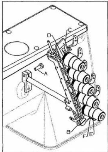
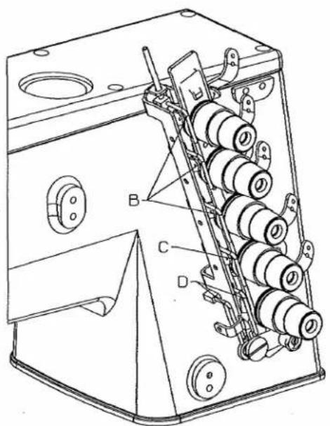
THREAD PULL-OFF
Pull-off hooks (B) for needle threads, control length of needle thread tails on a garment after trimming.
Set hooks (B) to strike-off shortest tail possible and still start sewing within the first or second stitch.
Set thread pull-off hook (C), for spreader thread so that thread is clamped securely when trimmed and starts properly when the stitch is first started. Lowering the needle thread pull off hooks will strike off more thread leaving longer tails.
Set hook (D), for the looper thread so that the thread is clamped securely when trimmed.
NOTE: Moving strike-off hooks down strikes off more thread. Moving strike-off hooks up strikes off less thread.
text_image
Technical diagram of a mechanical device with labeled parts A, B, C, and D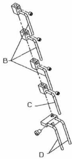
text_image
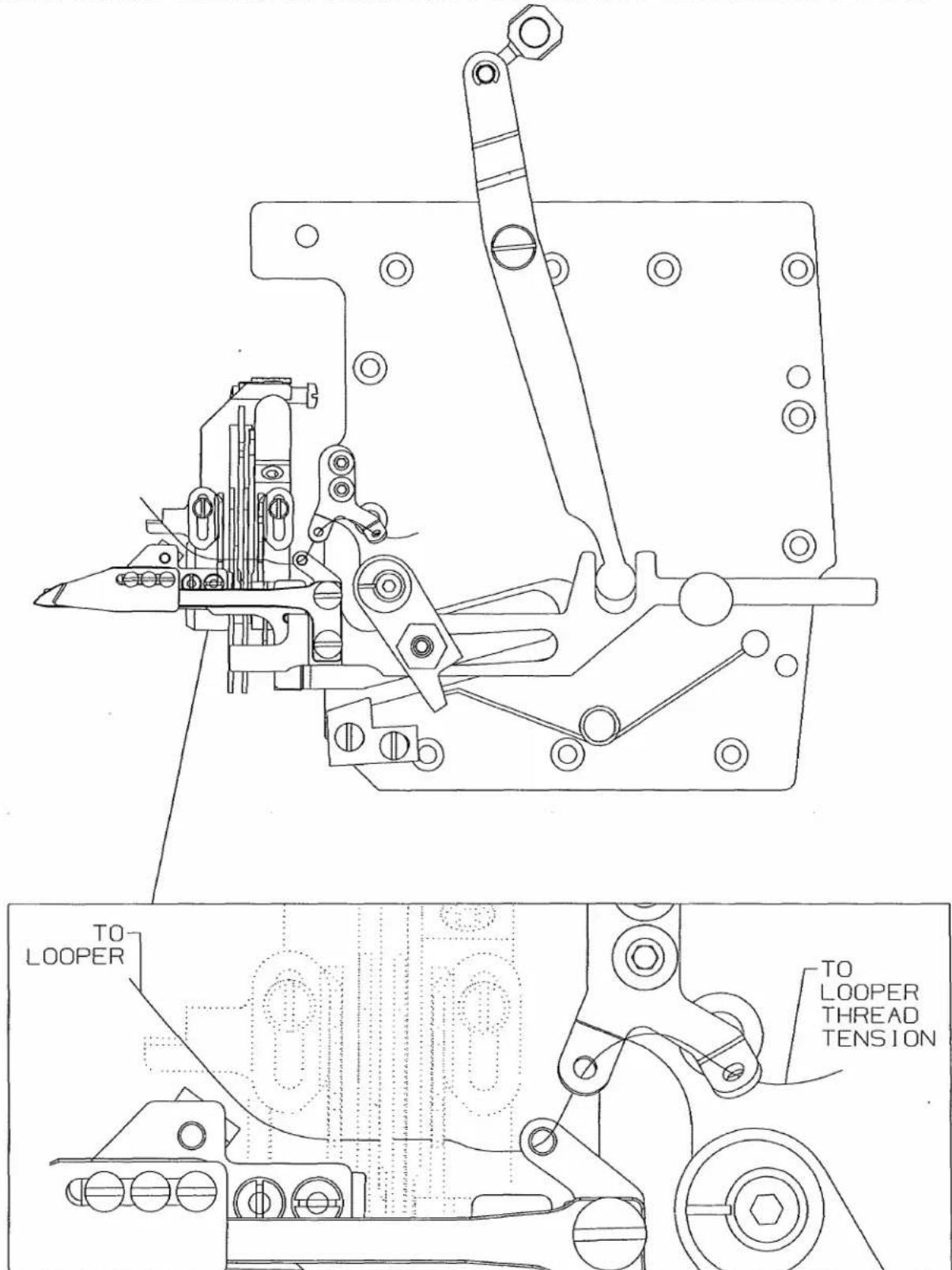
Technical diagram showing mechanical assembly with labeled components A, B, C, and DTHREADING DIAGRAM
Looper Thread Strike-Off
CAUTION: Improper threading may cause; looper thread wrap-ups or inconsistent start of stiches.
text_image
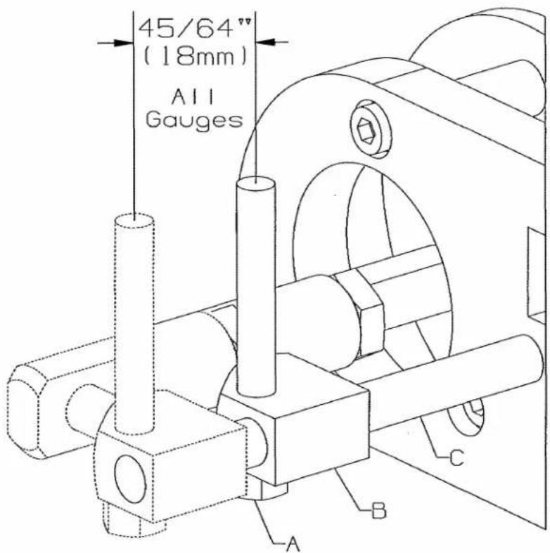
TO LOOPER TO LOOPER THREAD TENSIONUNDERBED THREAD TRIMMER (ELECTRIC)
Set stroke of the driving solenoid to: 45/64" (18mm). All gauges.
Remove the cloth plate.
Loosen nut (A).
Move crosshead (B) on shaft (C) as required.
Retighten nut (A).
text_image
45/64" (18mm) All Gauges A B CUNDERBED THREAD TRIMMER ASSEMBLY
When the thread trimmer is in its home position, the distance between edge (AA) and the protruding edge of lever (D) should be: 1/64" (0.4mm).
Remove retainer ring (E).
Push down on driving link to remove from hole in arm (G).
Turn driving link(F) in or out as required.
Release driving link (F) making sure pin is in hole in arm (G).
Replace retainer ring (E).

text_image
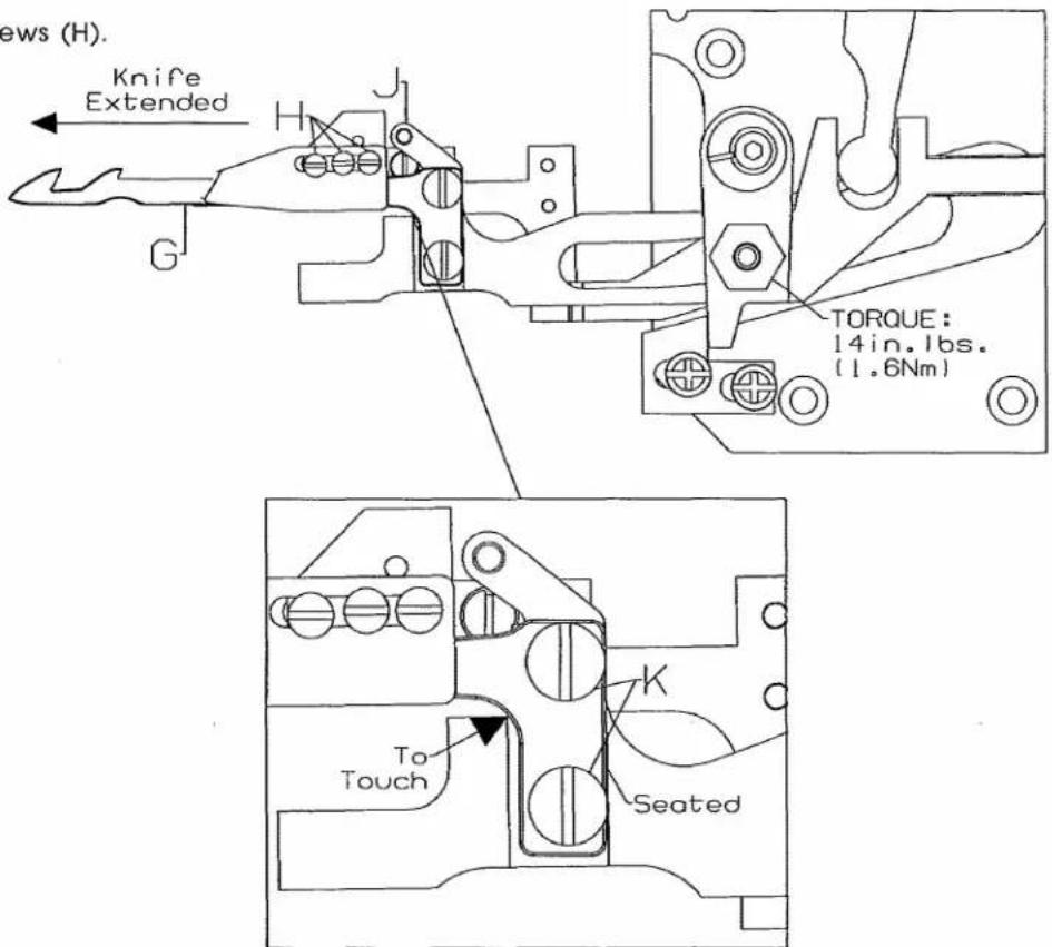
1/64" (0.4mm) AA D E F GUNDERBED THREAD TRIMMER ASSEMBLY Knife Adjustment
When positioning lower knife (G), eyelet (J) must be seated to the right.
Lower knife (G) must be seated to the right and all the way forward when tightened.
Loosen 2 screws (K).
Move eyelet (J) to the right as required.
Set lower knife as required.
Retighten screws (K).
To ensure no binds, extend knife (G) to the left and loosen upper knife screws (H) at the same time.
Retighten screws (H).
text_image
ews (H). Knife Extended G TORQUE: 14in.1bs. (1.6Nm) K To Touch SeatedUNDERBED THREAD TRIMMER ASSEMBLY
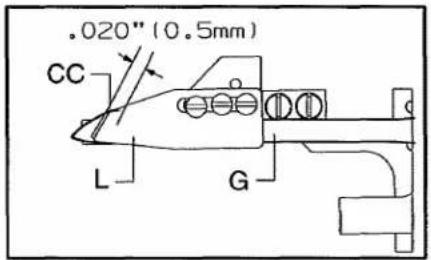
Upper knife (L) should overlap lower knife (G) by: .020" (0.5mm).
The distance from clamping leaf spring (N) to the tip of lower knife (G) should be: 1/8" (3mm). Clamping leaf spring (N) should be flush with knife at edge (BB).
NOTE: The clamping leaf spring must be set to only clamp the looper thread, NOT the needle threads.
The distance from tension leaf spring (M) to the back of upper knife (L, @ point CC) should be: .020" (0.5mm).
text_image
.020" (0.5mm) CC L G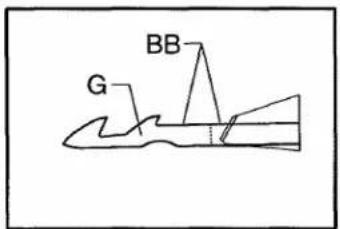
text_image
G BB
text_image
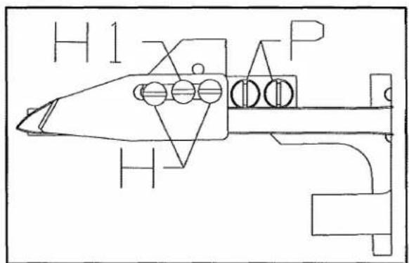
.020" (0.5mm) G 1/8" (3.2mm) N L M As viewed from the undersideUPPER KNIFE AND CLAMPING SPRING
Loosen two screws (H) and screw (H1).
Move upper knife (L) and clamping leaf spring (N) as required.
Retighten screws (H) and (H1).
TENSION SPRING
Loosen two screws (P).
Adjust leaf spring (M) as required.
Retighten screws.
text_image
H1 P HUNDERBED THREAD TRIMMER ASSEMBLY
With the needles at top dead center: Lower knife (G) should be extended past the heel of looper (Q) by: 15/32" (12.0mm), for the following adjustments.
The tip of lower knife (G) should be centered front to back, to the rear edge of the flat on top of looper (Q).
Stop (R) sets the distance of the upper knife and springs to the looper, it should be centered in its slots.
Guide (S) should just contact edge (DD) of knife mechanism.
On cover stitch machines (G) should be set slightly rearword .005" (.10mm) of the standard adjustment.
The bottom of lower knife (L) should clear looper (Q) by .004" (0.1mm).
Move eccentric (U) as required.
Retighten screw (T).
STOP DISTANCE
Loosen screws (V).
Move stop (R) as required.
Retighten screws (V).
GUIDE DISTANCE
Loosen screws (W).
Move guide (S) as required to just contact edge (DD).
Retighten screws (W).
Loosen screws (W). Move guide (S) as required to obtain .004" (0.1mm) dimension.
Retighten screws (W).

text_image
15/32" (12.0mm) Q G L DD LS R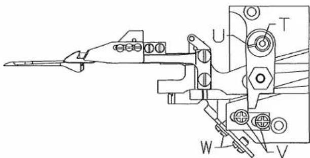
text_image
Technical diagram of a mechanical assembly with labeled components U, T, W, and V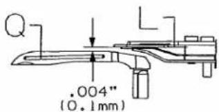
text_image
.004" (0.1mm)
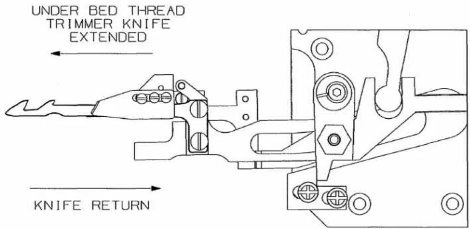
UNDERBED THREAD TRIMMER
ELECTROPNEUMATIC DRIVE
Adjust the metering screws so that thread trimmer mechanism and knife move smoothly left to right and the threads are cleanly cut and clamped.
text_image
UNDER BED THREAD TRIMMER KNIFE EXTENDED KNIFE RETURNTo increase the speed of the knife return, turn screw (A) counterclockwise.
To decrease the speed of the knife, turn screw (A) clockwise.
To increase the speed of extending the knife, turn screw (B) counterclockwise.
To decrease the speed of extending the knife, turn screw (B) clockwise.

text_image
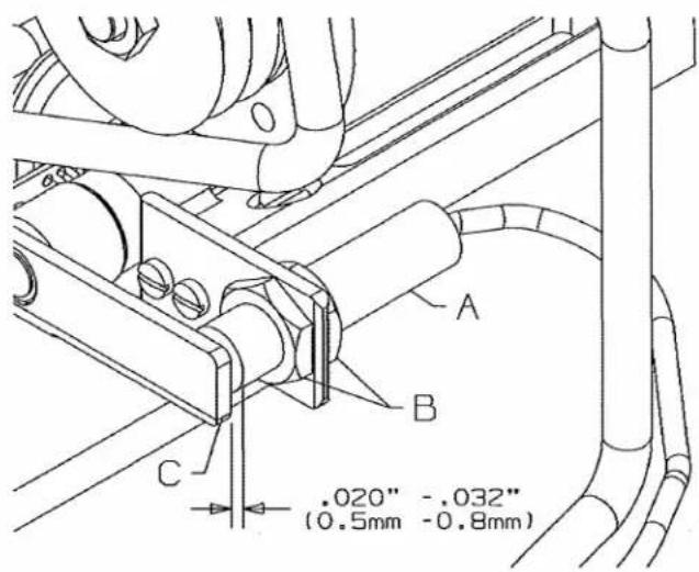
Technical diagram of an electrical component with labeled terminals A and B, showing internal circuit connections and mounting points.SETTING PROXIMITY SWITCH
Proximity switch prevents motor from running when thread trimmer mechanism is not in extreme right position.
When moving thread trimmer mechanism 0.020" (0.5mm) to left LED must go out, motor will not start.
Move thread trimmer mechanism to its extreme right (end) position.
Switch on motor (do not run).
Loosen nuts (B).
Adjust switch (A) closer to lever (C) until LED illuminates.
Distance should be between 0.020 to 0.032" (0.5 to 0.8mm).
text_image
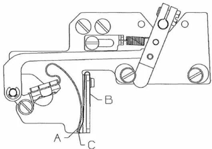
A B C .020" -.032" (0.5mm -0.8mm)SOLENOID/PNEUMATIC THREAD WIPER
Bracket installed at 90 angle to needles.
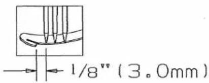
Wiper hook (A) must deflect needle threads to operator on downstroke, (Fig. 1). Also the catch of the hook must pass the left needle by 1/8^n (3.0mm).
On return, wiper hook must catch all needle threads (Fig. 2) and draw them into leaf spring (B) to be clamped.
Wiper hook (A) and leaf spring (B) should be flush at point (C) when at rest position.
text_image
Technical diagram of a mechanical clamp or bracket assembly with labeled parts A, B, and C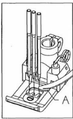
natural_image
Technical line drawing of a microscope with labeled component A (no text or symbols beyond label)FIG.1
text_image
1/8" (3.0mm)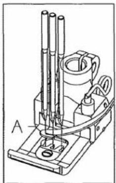
natural_image
Technical line drawing of a mechanical device with three vertical rods and a central cylindrical component (no text or symbols)FIG.2
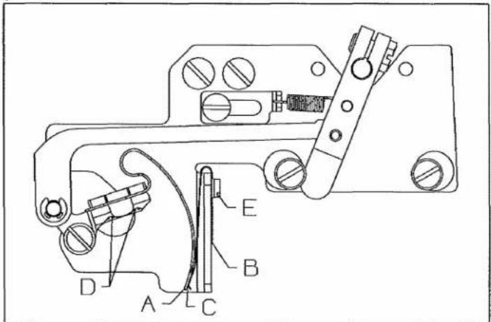
ADJUSTING THREAD WIPER
Disconnect power supply for thread wiper.
Loosen screws (D). Move wiper (A) left or right as necessary.
Retighten screws (D).
Operate wiper manually to check ajustment.
Loosen screw (E), move leaf spring (B) flush with wiper (A) at point (C).
Retighten screw (E).
Reconnect power supply.
text_image
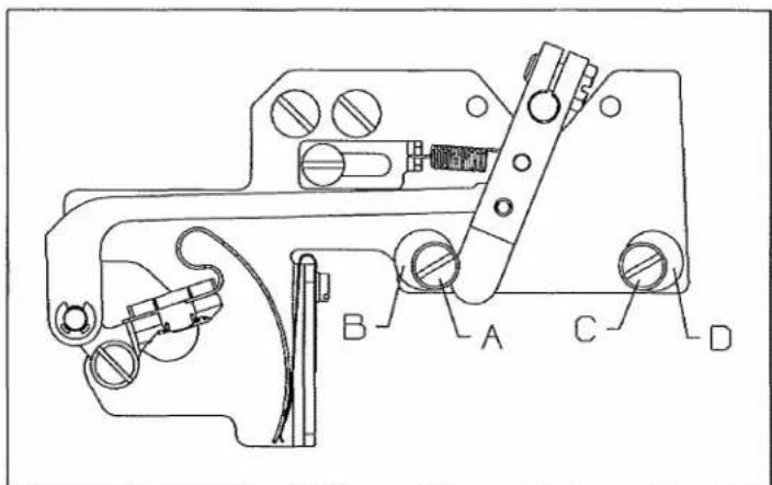
Technical diagram of a mechanical device with labeled parts A, B, C, D, E and internal componentsTo lengthen travel past left needle.
Disconnect power supply to thread wiper.
Loosen stop screw (A) and rotate eccentric (B) so high lobe is further to left. Retighten stop screw (A).
To move wiper higher in leaf spring.
Loosen screw (C) and rotate eccentric (D) so high lobe is further to the right. Tighten stop screw (C).
Reconnect power supply.
NOTE: Recheck leaf spring setting to wiper.
text_image
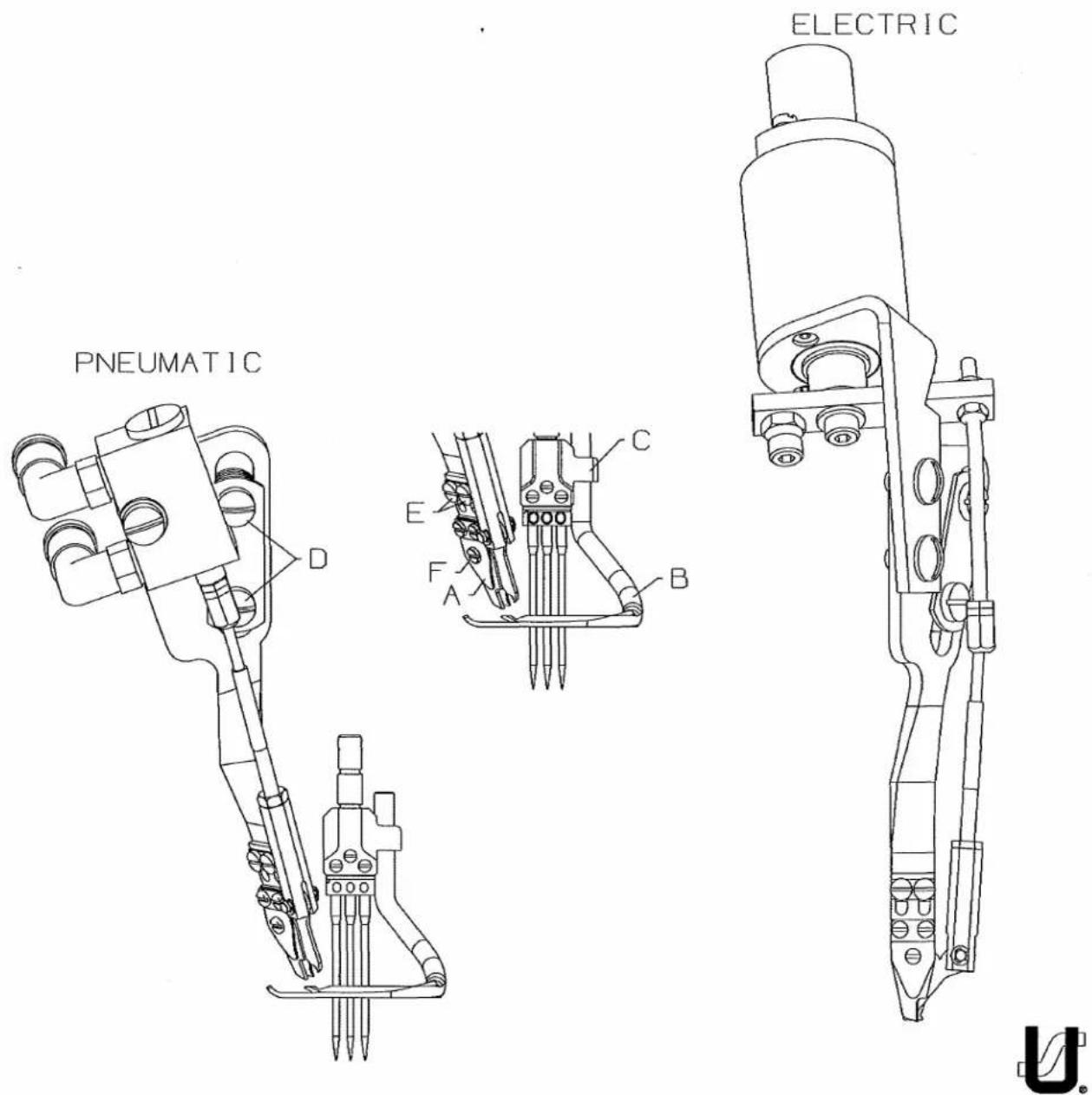
Technical diagram of a mechanical device with labeled parts A, B, C, D and internal componentsPNEUMATIC/ELECTRIC COVER THREAD TRIMMER
Cover thread trimmer is positioned so that moveable thread catches knife (A):
Clear recess in spreader (B).
Does not interfere with needle head (C).
Cuts cleanly and clamps spreader thread.
To move trimmer away from or closer to spreader (B), loosen screws (D).
Recheck position to recess in spreader (B) and clearance to needle head (C).
To position trimmer to recess in spreader (B) loosen screws (E). Reposition moveable thread catch knife (A). Tighten screws (E).
Set the pressure of knife (F) to the minimum and still cut the spreader thread.
text_image
PNEUMATIC E C A B ELECTRICSETTING THREAD CATCH KNIFE STROKE
Knife (A) must open wide enough to catch spreader thread.
Loosen nut (B), rotate connecting rod (C) clockwise to decrease stroke or counterclockwise to increase.
CAUTION:
When increasing stroke check that spacer (D) stops the cylinder stroke before thread catch knife (A) hits distance plate (E).

natural_image
Technical line drawing of a robotic arm with articulated joints and base mount (no text or symbols)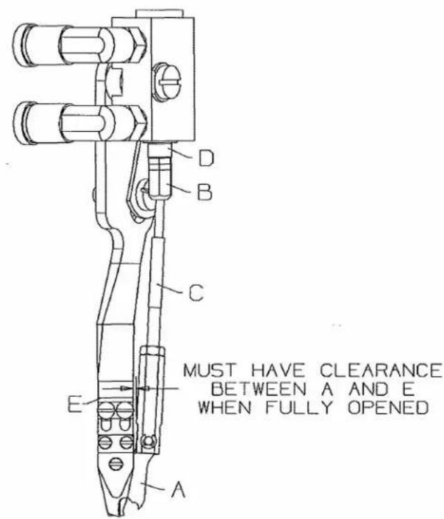
text_image
D B C E A MUST HAVE CLEARANCE BETWEEN A AND E WHEN FULLY OPENEDNEEDLE THREAD BLOWER ASSEMBLY
Needle threads must be blown out from under a raised presser foot after material has been removed.

natural_image
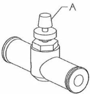
Technical line drawing of a mechanical assembly with no visible text or symbolsAIR FLOW
- Turn needle valve (A) clockwise to decrease air flow.
- Turn needle valve (A) counterclockwise to increase air flow.
natural_image
Technical line drawing of a mechanical valve component (no text or symbols)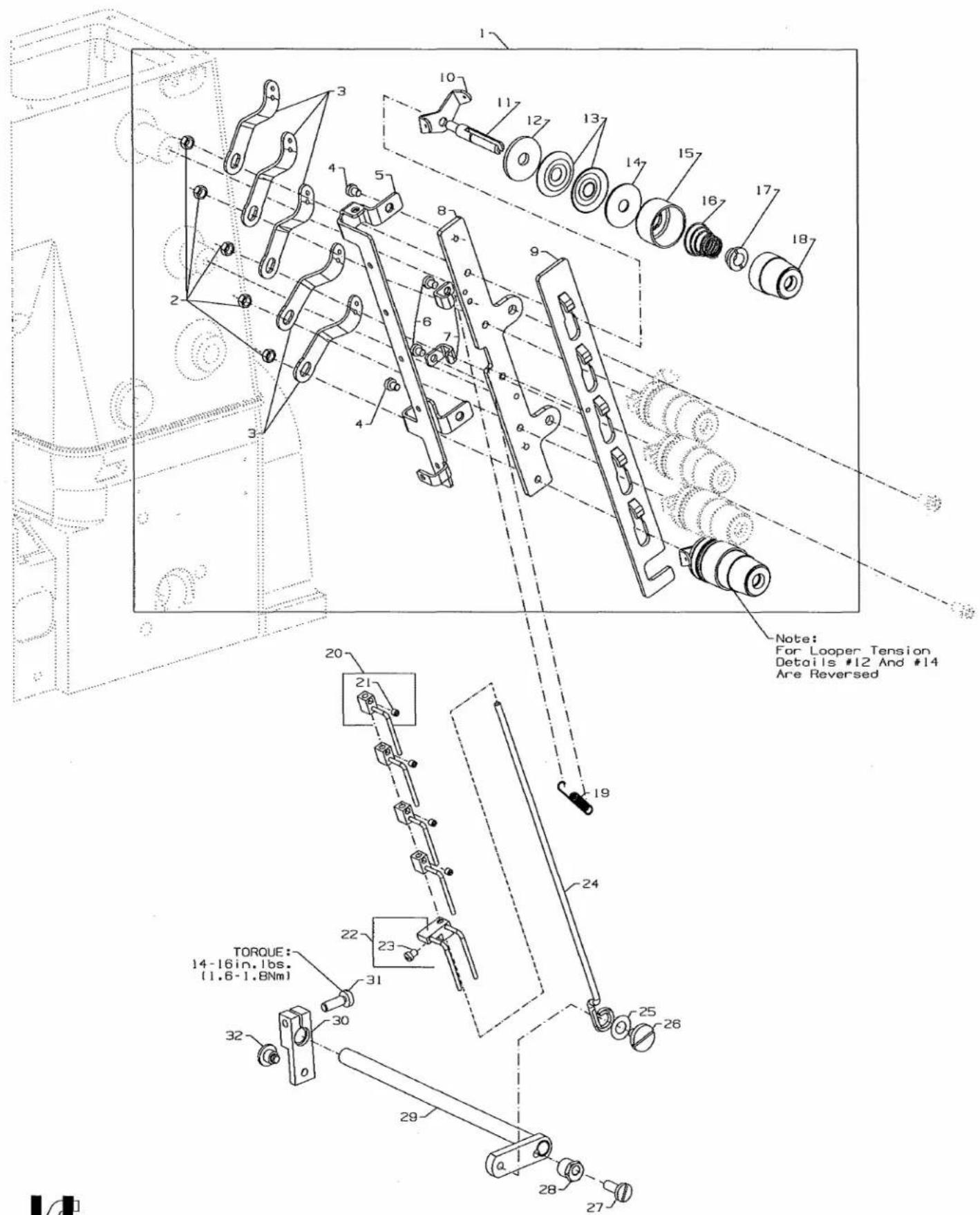
text_image
Note: For Looper Tension Details #12 And #14 Are Reversed TORQUE: 14-16in. lbs. (1.6-1.8Nm) 19 20 21 22 23 30 31 32 33 34 35 36 37 38 39 40 41 42 43 44 45 46 47 48 49 50 51 52 53 54 55 56 57 58 59 60 61 62 63 64 65 66 67 68 69 70 71 72 73 74 75 76 77 78 79 80 81 82 83 84 85 86 87 88 89 90 91 92 93 94 95 96 97 98 99 100THREAD TENSION
Ref. No. Part No. Description Amt. Req.
- 29477NL 5 Thread Tension Assembly 1
- NS6110420SP Nut 5
- 57865 Lead-in Thread Guide 5
- SS7090520SP Screw 2
- 50392AP Thread Guide 1
- SS7090520SP Screw 2
- 50392AV Guide, for tension disc separator 2
- 50392X Tension Bracket 1
- 50392AR Tension Disc Separator 1
- 57892K Thread Tension Eyelet 5
- 56392G Tension Post 5
- B3120704000 Tension Disc Felt 5
- B3126012000 Tension Disc 10
- B3120352000 Tension Disc Felt 5
- 56392H Spring Shield 5
- B3103804000 Spring, for spreader (blue) 1
- B3101804000 Spring, for needle (red) 3
- B3121804000 Spring, for looper (plain) 1
- B3112704000 Ferrule, for tension spring 5
- 56392M Knob, for spreader (blue) 1
- 56392L Knob, for needle (red) 3
- 50392R Knob, for looper (plain) 1
- 96711 Extension Spring 1
- 50358Y Thread Pull-off Hook 4
- 28C Screw 4
- A9858 Thread Pull-off Hook 1
- 77A Screw 1
- 50392AS Puller Rod, for thread puller 1
- 50374A Washer 1
- 99296 Shoulder Screw 1
- 22757 Screw 1
- G51346KA Tension Release Eccentric 1
- 50392AN Tension Release Assembly 1
- 99620 Tension Release Lever 1
- 22596 Screw 1
- 22735 Screw 1
| UT COMPONENT DEVICE KEY | |
| UT DEVICE | COMPONENT USEDON DEVICE |
| UT1CS1 | ● |
| UT2CS1 | ● |
| UT3CS1 | ● |
| UT4CS1 | ● |
| UT5CS1 | ● |
text_image
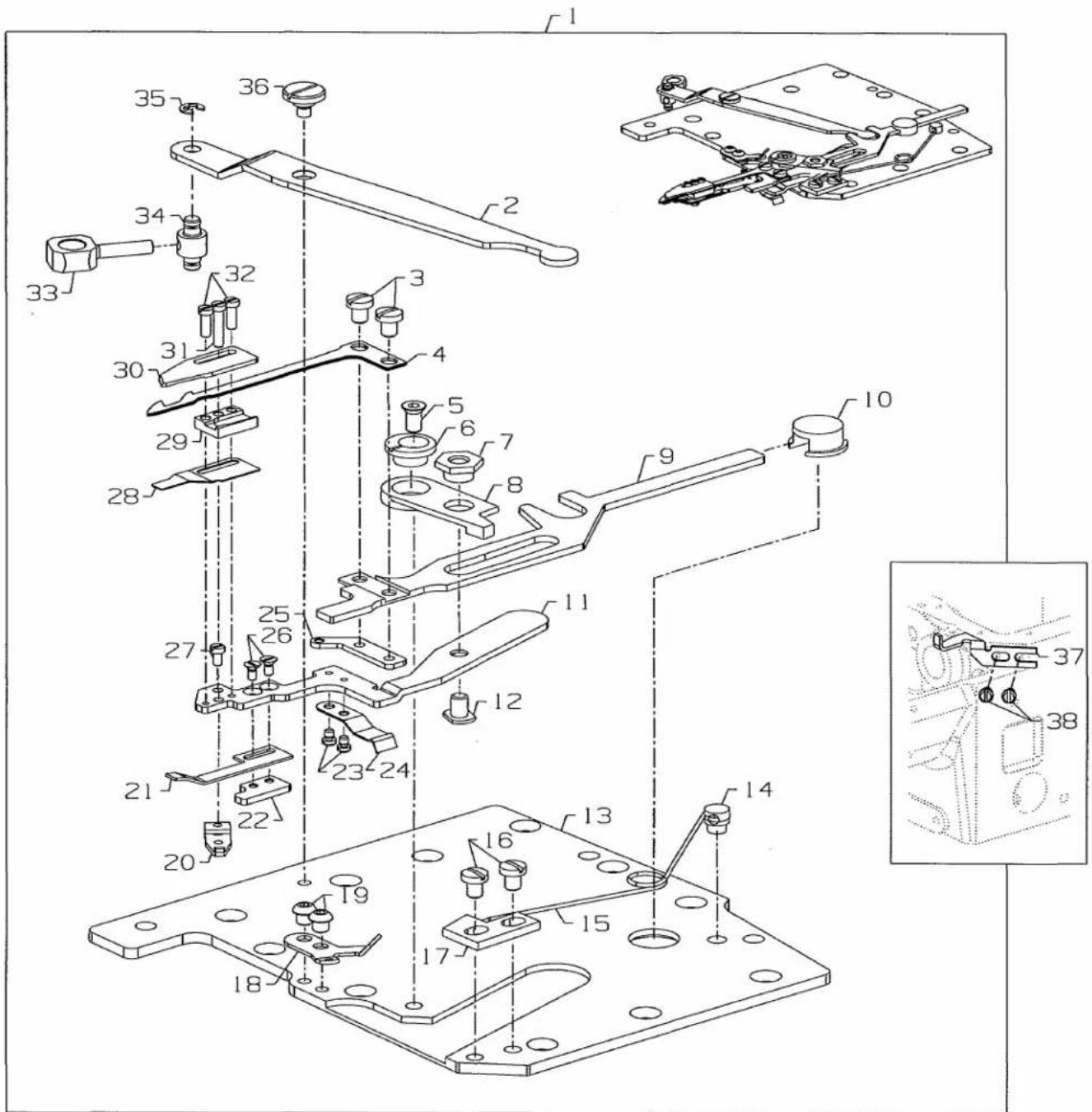
Technical diagram of a mechanical assembly with numbered components, likely an engine or assembly tool.UNDERBED THREAD TRIMMER ASSEMBLY
| Ref. | Amt. | ||
| No. | Part No. | Description | Req. |
- 29480AWB Underbed Thread Trimmer Assembly 1
- 34763P Lever 1
- 18-1453 Screw 2
- 34749P Lower Knife 1
- 18-1450 Screw 1
- 34768A Eccentric Guide 1
- 34768C Guide Washer 1
- 34750R Lever 1
- 34750T Lower Knife Holder 1
- 34750U Guide 1
- 34750SA Upper Knife Holder 1
- 18-1472 Screw 1
- 34382AC Oil Reserve Cover 1
- 34751MS Pin 1
- 50332AD Spring 1
- 18-1449 Screw 2
- 34775H Stop 1
- 50366D Looper Thread Guide 1
- 18C1471 Screw 2
- 34751MT Tension Lever 1
- 34773D Leaf Spring 1
- 34769B Threaded Plate 1
- SM6020250TP Screw 2
- 34773E Leaf Spring 1
- 50368AE Looper Thread Pull-off Eyelet 1
- SM1020450TP Screw 2
- 18-1473 Screw 1
- 34773F Leaf Spring 1
- 34750P Lower Knife Guide 1
- 34770M Upper Knife 1
- SM6021000TP Screw 1
- SM6020600TP Screw 2
- 34752M Driving Link 1
- 34752N Carrier Bolt 1
- RE025000KO E-Ring 1
- SD0600176SP Screw 1
- 34794A Guide 1
- 90 Screw, for guide 2
| UT COMPONENT DEVICE KEY | |
| UT DEVICE | COMPONENT USEDON DEVICE |
| UT1CS1 | ● |
| UT2CS1 | ● |
| UT3CS1 | ● |
| UT4CS1 | ● |
| UT5CS1 | ● |

text_image
1 2 3 4 5 3 B 9 10 11 7 8 8 6 13 14 13 15 8 8 5 16 17 12 17 AS VIEWED FROM THE BACK OF THE MACHINE.ELECTRIC PRESSER FOOT LIFTER ASSEMBLY
Ref. No. Part No. Description Amt. Req.
- 29921D Electric Drive Assembly 1
- NS6150430SP Nut 3
- 95951 Washer 4
- 50367H Lifter 1
- SS9151420TP Hex Screw 4
- 670K29 Solenoid Assembly 1
- 92855A Cap 1
- SS4051281SE Screw 6
- 50395N Stud 1
- NS6660430SP Nut 1
- 50333B Coupling 1
- SS6110710TP Screw 1
- GAK33034000 Bracket 2
- GAK8403000A Solenoid 1
- GAK3303600A Cap 1
- WS0631510KP Lock Washer 2
- 53636C Washer 3
- SS9111010SP Hex Screw 4
- WS0510002KP Lock Washer 4
- 50395P Stand-Off 4
- 4611U Washer 4
- 50395R Clamp Plate 1
- 50383S Base Plate 1
| UT COMPONENT DEVICE KEY | |
| UT DEVICE | COMPONENT USEDON DEVICE |
| UT1CS1 | ● |
| UT2CS1 | ● |
| UT3CS1 | |
| UT4CS1 | |
| UT5CS1 | |
text_image
Technical diagram of a mechanical assembly with numbered components for identification1
ELECTRIC THREAD WIPER ASSEMBLY
| Ref. | Amt. | ||
| No. | Part No. | Description | Req. |
- 29906M Electric Thread Drive Assembly 1
- 96280 Retaining Ring 2
- 99591DN Pin 1
- 99545G Push Rod 1
- PH0300083U0 Pin 1
- 99646J Lever
- SS9120910TP Screw 1
- SS4091015SP Screw 2
- 50363BF Stop Eccentric 2
- 99650E Wiper Bracket 1
- 670K15 Electric Solenoid Rotary 1
- 99545H Nut Plate 1
- SS6060210SP Screw 1
- 96150 Washer 1
- 99697AA Leaf Spring 1
- SS7090610SP Screw 2
- 51250C Hex Nut 1
- SS6060510TP Screw 2
- 50362B Plate 1
- 99653B Wiper Hook 1
- 99657E Lever 1
- 96161 Washer 1
- 99358 Shoulder Screw 1
- SS7090510SP Screw 1
- 99591DP Bracket 1
- 50332AB Extension Spring 1
| UT COMPONENT DEVICE KEY | |
| UT DEVICE | COMPONENT USED ON DEVICE |
| UT1CS1 | ● |
| UT2CS1 | |
| UT3CS1 | |
| UT4CS1 | |
| UT5CS1 | |
text_image
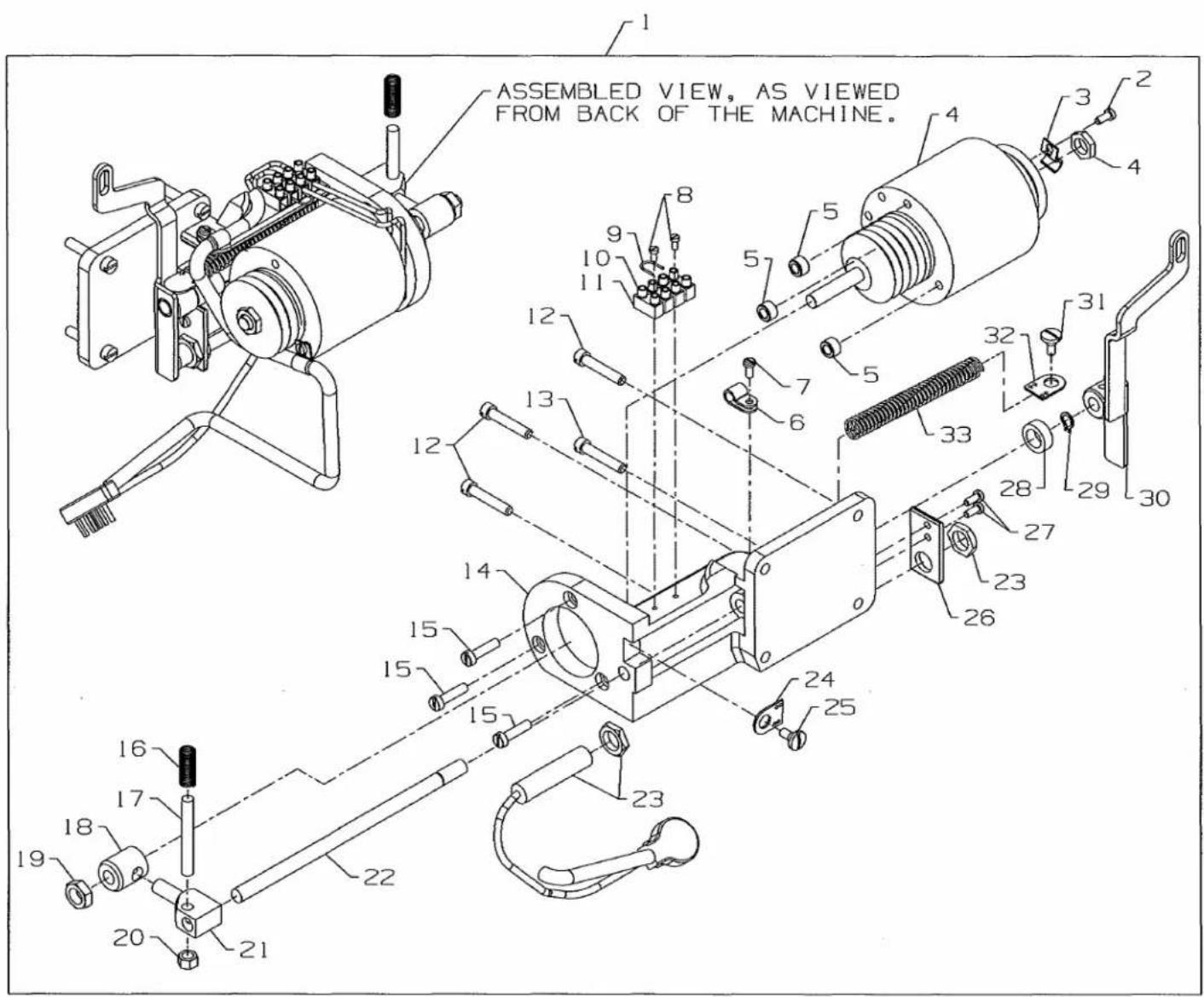
ASSEMBLED VIEW, AS VIEWED FROM BACK OF THE MACHINE.ELECTRIC DRIVE DOUBLE ACTION ASSEMBLY
Ref.
No. Part No.
Description
Amt.
Req.
- 670K28 Electric Drive Assembly 1
- 95169 Screw 1
- G21233BG Cable Clamp 1
- 998-306B Solenoid 1
- 99617A Bushing 3
- 998-358E Hose Clamp 2
- 22542 Screw 1
- 95179K Screw 2
- 1318001 Wire 1
- 670E1302 Terminal Block 1
- 998-297A Cable End Plate 2
- 22852A Screw 3
- 22517A Screw 1
- G52882KW Mounting Bracket 1
- 95177 Screw 3
- 51292F2 Spring 1
- 99619 Clamping Screw 1
- 99616 Driving Connection .... 1
- 95251 Nut 1
- 55235E Nut 1
- 99614D Cross Head 1
- 99613D Shaft 1
- 670E815 Switch Assembly 1
- 80696RA Spring Eyelet 1
- 14076 Screw 1
- 34762 Bracket 1
- 22585 Screw 2
- 99615 Washer 1
- 96261 Retaining Ring 1
- 50373DG Lever 1
- 22569B Screw 1
- 80696RA Spring Eyelet 1
- 96721 Spring 1
| UT COMPONENT DEVICE KEY | |
| UT DEVICE | COMPONENT USEDON DEVICE |
| UT1CS1 | ● |
| UT2CS1 | ● |
| UT3CS1 | |
| UT4CS1 | |
| UT5CS1 | |

text_image
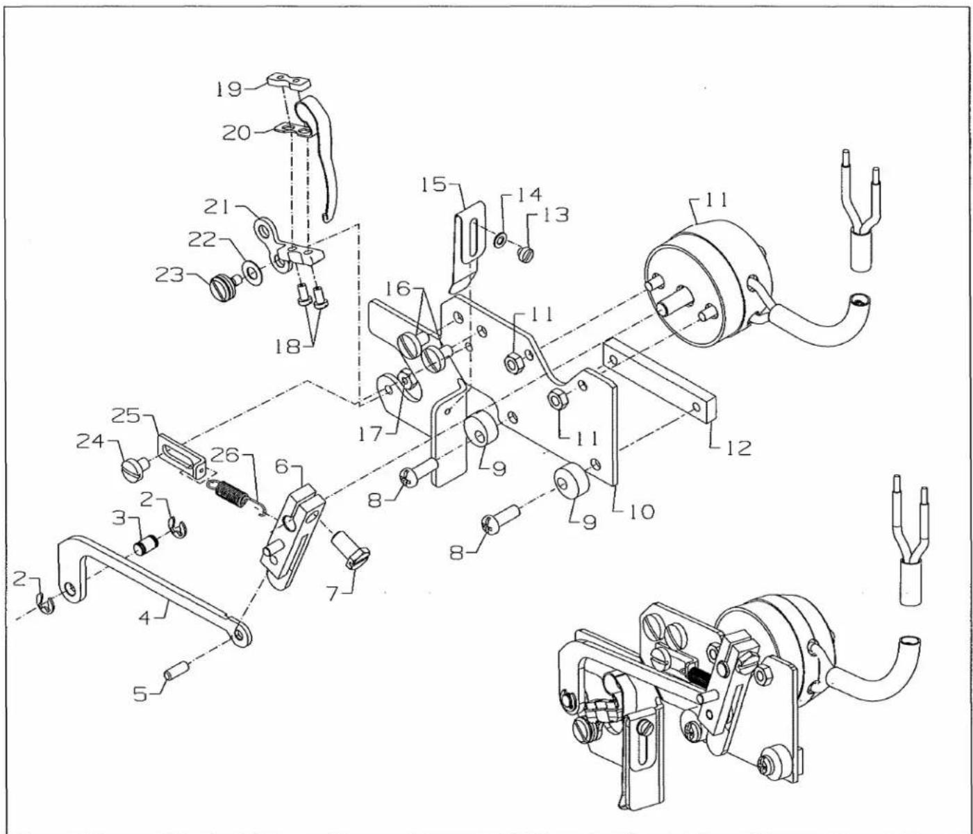
Technical schematic diagram of a mechanical assembly with numbered components and exploded viewsELECTRIC SPREADER THREAD TRIMMER ASSEMBLY
| Ref. | Amt. | ||
| No. | Part No. | Description | Req. |
-
29980LC Spreader Thread Trimmer Assembly, Electric .... 1
-
95166V Screw 2
-
41358T Washer 2
-
50382GY Cover Spring 1
-
995-705AS Spring 1
-
670K27 Solenoid 1
-
50386A Washer 1
-
50395M Stud 1
-
50383R Solenoid Bracket 1
-
50383P Mounting Plate 1
-
95259 Nut 4
-
50345Y Connecting Rod 1
-
95409D Screw 2
-
95954 Washer 1
-
95257 Nut 1
-
22848 Screw 2
-
95435A Screw 2
-
SS4121415SA Screw 2
-
34751MF Washer Plate 2
-
50372DG Holder 1
-
69H Washer 2
-
34751MJ Hex Head Screw 1
-
34751MK Ball 1
-
34751ML Nut 1
-
50322AY Rod 1
-
660-1097 Retainer 2
-
50347S Pin 1
-
50322AX Yoke 1
-
22738U Screw
-
22738 Screw 2
-
34751ME Leaf Spring 1
-
50349C Fixed Knife 1
-
34751MC Plate 1
-
34770LB Knife 1
-
22798A Screw 2
-
34751MR Plate 1
-
34751MB Plate 1
-
34751MD Square Collar 1
-
60078Z Nut 1
-
998-358E Hose Clamp 1
| UT COMPONENT DEVICE KEY | |
| UT DEVICE | COMPONENT USEDON DEVICE |
| UT1CS1 | |
| UT2CS1 | ● |
| UT3CS1 | |
| UT4CS1 | |
| UT5CS1 | |

text_image
To: 29921C Pneumatic Presser Foot Lifter Assembly To: B To: 29480ATW pneumatic drive assembly 1 2 3 4 5 6 TO: air supplyPNEUMATIC CONTROL
| Ref. | Amt. | ||
| No. | Part No. | Description | Req. |
- 29480ASU Pneumatic Control Kit 1
- 90561K Wood Screw 2
- 99683CP Mounting Bracket 1
- 671D42 Filter/ Regulator Assembly 1
- 671F88 Barb Fitting 1
- 671F81A Elbow Fitting - 6mm x 1/2" NPT 1
- 671B182 Air Tubing - 6mm O.D. x 1m (not shown) 1
- 29480AST Presser Foot Lifter Kit 1
- 671F81C Elbow Fitting - 6mm x 1/8" NPT 2
- 95415 Screw - 4mm 2
- 660-403 Muffler 1
- 671-50 Valve 1
- 671F86B Splitter 1
- 670E673 Cable Harness (not shown) 1
- RM2724A Connector (male, not shown) 2
- 671B23 Air Tubing - 6mm O.D. x 1mm (not shown) 1
| UT COMPONENT DEVICE KEY | |
| UT DEVICE | COMPONENT USED ON DEVICE |
| UT1CS1 | |
| UT2CS1 | |
| UT3CS1 | ● |
| UT4CS1 | |
| UT5CS1 | ● |
text_image
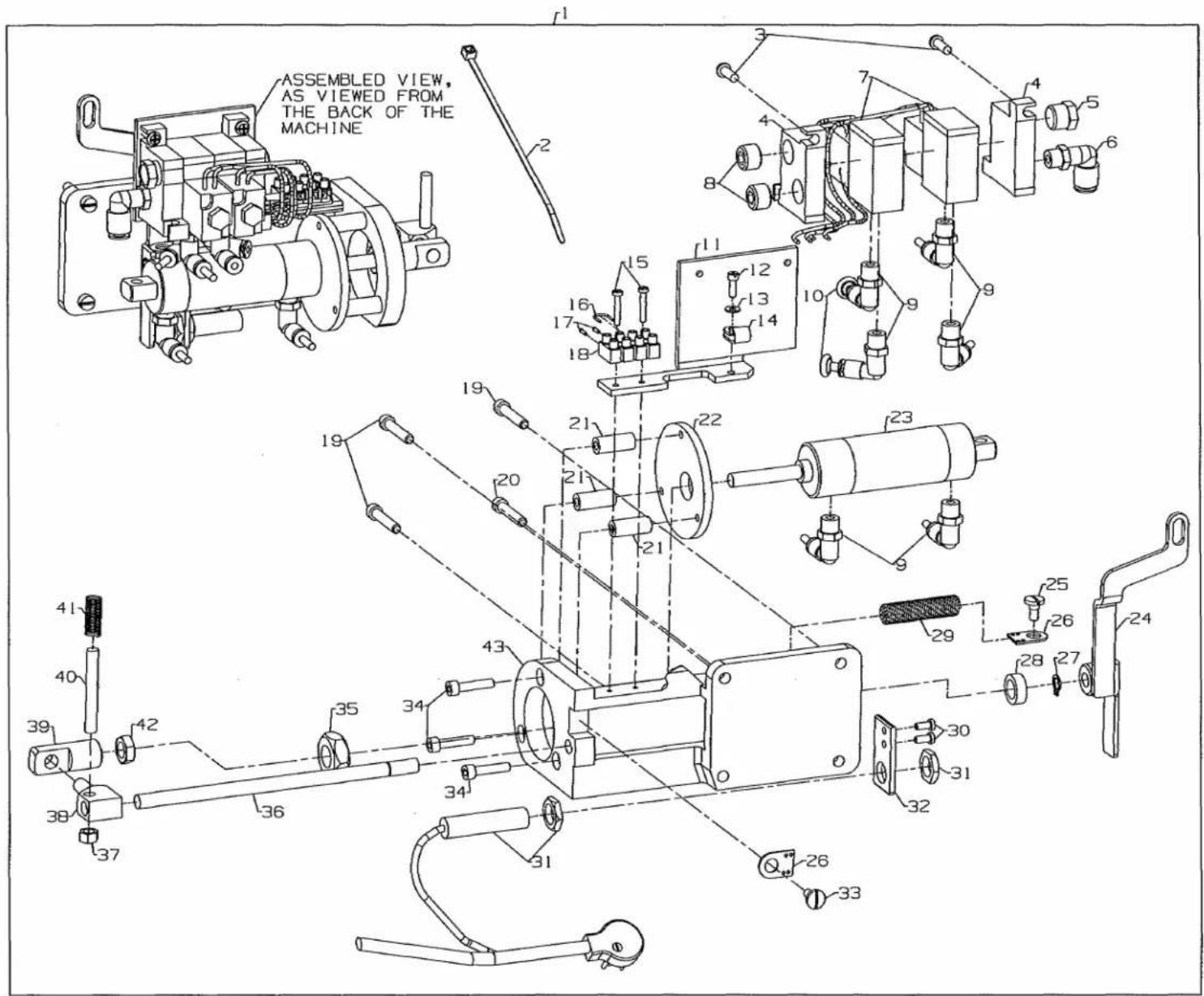
ASSEMBLED VIEW, AS VIEWED FROM THE BACK OF THE MACHINEPNEUMATIC DRIVE DOUBLE ACTION ASSEMBLY
| Ref. No. | Part No. | Description | Amt. Req. |
| 1. | 29480ATW | Pneumatic Drive Assembly | 1 |
| 2. | RM2871B | Cable Tie | 2 |
| 3. | SS4121415SP | Screw | 2 |
| 4. | 671-104A | Manifold | 1 |
| 5. | 660-763 | Silencer | 1 |
| 6. | 671F81A | Elbow | 1 |
| 7. | 671-103B | Mac Valve | 2 |
| 8. | 671F87 | Plug | 2 |
| 9. | 671F82C | Elbow | 6 |
| 10. | 670G276 | Plug | 2 |
| 11. | 50383N | Bracket | 1 |
| 12. | 22729 | Screw | 1 |
| 13. | 95954 | Washer | 1 |
| 14. | 998-358E | Cable Clamp | 1 |
| 15. | 22894AX | Screw | 2 |
| 16. | 1318001 | Wire | 1 |
| 17. | 998-297A | Cable End Sleeve | 2 |
| 18. | 670E1302 | Terminal | 1 |
| 19. | 22852A | Screw | 3 |
| 20. | 22517A | Screw | 1 |
| 21. | 99617T | Spacer | 3 |
| 22. | 99591DH | Disc | 1 |
| 23. | 99694A | Air Cylinder | 1 |
| 24. | 50373DG | Lever | 1 |
| 25. | 22569B | Screw | 1 |
| 26. | 80696RA | Spring Eyelet | 1 |
| 27. | 96261 | Retaining Ring | 1 |
| 28. | 99615 | Washer | 1 |
| 29. | 96721 | Spring | 1 |
| 30. | 22585 | Screw | 2 |
| 31. | 670E815 | Switch Assembly | 1 |
| 32. | 34762 | Bracket | 1 |
| 33. | 14076 | Stud | 1 |
| 34. | 95411 | Screw | 3 |
| 35. | 99327 | Nut | 1 |
| 36. | 99613D | Shaft | 1 |
| 37. | 55235E | Nut | 1 |
| 38. | 99614D | Cross Head | 1 |
| 39. | 99616A | Connector | 1 |
| 40. | 99619 | Clamping | 1 |
| 41. | 51292F2 | Spring | 1 |
| 42. | 21233FB | Nut | 1 |
| 43. | G52882KW | Support Bracket | 1 |
| 671B182 | Tubing (not shown) | 2ft. | |
| 6-878 | Nylon Black Tubing (not shown) | 1 | |
| 998-358E | Hose Clamp (not shown) | 1 |
| UT COMPONENT DEVICE KEY | |
| UT DEVICE | COMPONENT USEDON DEVICE |
| UT1CS1 | |
| UT2CS1 | |
| UT3CS1 | ● |
| UT4CS1 | ● |
| UT5CS1 | ● |

text_image
Technical diagram of a mechanical assembly with numbered components and labeled partsPNEUMATIC THREAD WIPER ASSEMBLY
Ref.
No. Part No.
Description
Amt.
Req.
- 29906L Pneumatic Thread Wiper Assembly 1
- 95167CV Screw 2
- 35086BK Clevis 1
- 95294 Hex Nut 1
- 999-191H Pneumatic Cylinder 1
- 999-411M5-4 Pneumatic Fitting 2
- PH0300083U0 Pin 1
- 95259 Hex Nut 2
- 95956 Washer 2
- 99650D Wiper Bracket 1
- SS4091015SP Screw 2
- 50363BF Stop Eccentric 2
- SS6080610TP Screw 2
- 99545H Nut Plate 1
- 52336B Pin 1
- 99545F Plate 1
- 96280 Retaining Ring 3
- SS6060210SP Screw 1
- 96150 Washer 1
- 99697AA Leaf Spring 1
- SS7090610SP Screw 2
- 51250C Hex Nut 1
- 99652A Washer 2
- 50362B Plate 1
- 99653B Wiper Hook 1
- 99657E Lever 1
- SS6060510TP Screw 2
- 96161 Washer 1
- 99358 Shoulder Screw 1
- 99591DN Pin 1
- 99545G Push Rod 1
- 35086BJ Roller 1
- 99646J Lever 1
- SS9120910TP Screw 1
| UT COMPONENT DEVICE KEY | |
| UT DEVICE | COMPONENT USEDON DEVICE |
| UT1CS1 | |
| UT2CS1 | |
| UT3CS1 | ● |
| UT4CS1 | |
| UT5CS1 | |
text_image
Technical diagram of a mechanical assembly with numbered components, likely for engineering or manufacturing documentation.PRESSER FOOT LIFTER
Ref.
No. Part No.
Description
Amt.
Req.
- SS6122030SP Screw 1
- 50383AR Cylinder Support Bracket 1
- NS6120310SP Nut 1
- WS0510002KP Washer 1
- SS4121015SP Screw 1
- 50374K Spacer 1
- 29480AXJ Presser Foot Lifter Assembly 1
- 671A360 Air Cylinder 1
- 671F81C Fitting 1
- 50383AF Bracket 1
- 660-1099 Air Cylinder Cap 1
- SS4121215SP Screw 2
| UT COMPONENT DEVICE KEY | |
| UT DEVICE | COMPONENT USEDON DEVICE |
| UT1CS1 | |
| UT2CS1 | |
| UT3CS1 | ● |
| UT4CS1 | ● |
| UT5CS1 | ● |
natural_image
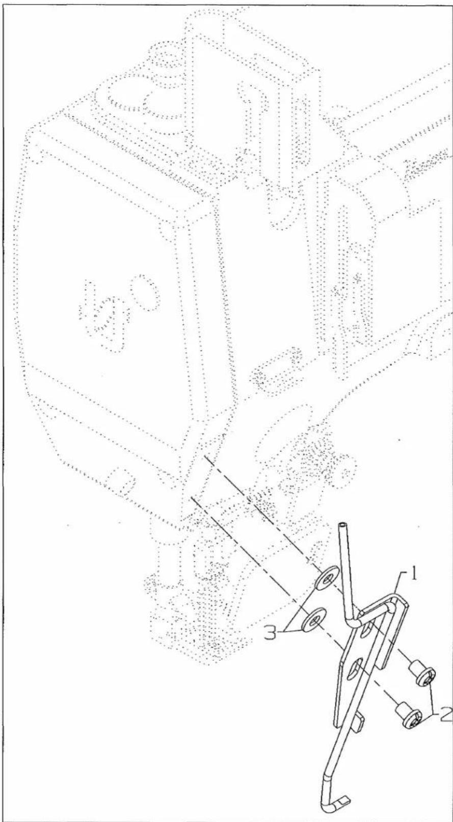
Technical line drawing of a mechanical assembly with numbered components (no text or symbols)NEEDLE THREAD BLOWER ASSEMBLY
Ref.
No. Part No.
Description
Amt.
Req.
- 50394AJ Needle Thread Blower Assembly 1
- SS4120615SP Screw, for needle thread blower assembly 2
- 69H Washer 2
| UT COMPONENT DEVICE KEY | |
| UT DEVICE | COMPONENT USED ON DEVICE |
| UT1CS1 | |
| UT2CS1 | |
| UT3CS1 | |
| UT4CS1 | ● |
| UT5CS1 | |
text_image
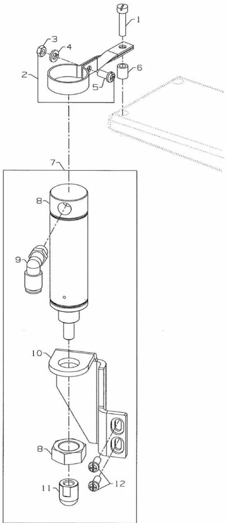
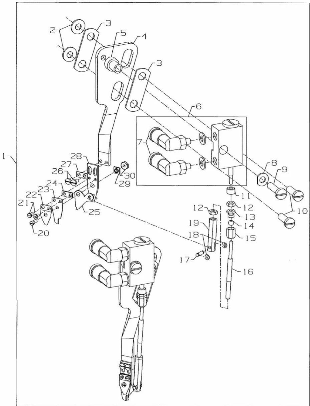
Technical diagram of a mechanical assembly with numbered components and exploded view, likely for engineering or manufacturing documentation.PNEUMATIC COVER THREAD TRIMMER ASSEMBLY
Ref.
No. Part No.
Description
Amt.
Req.
- 29980LB Pneumatic Cover Thread Trimmer Assembly 1
- 69H Washer 2
- 34751MF Washer Plate 2
- 50372DG Holder 1
- 99683VF4 Bushing 1
- 99683VG Air Cylinder 1
- 999-411M5-4 Coupling 2
- 39278C Washer 1
- 93B Screw 1
- SS4121415SP Screw 2
- 34751MH Spacer 1
- 95259 Nut 2
- 34751MJ Hex Head Screw 1
- 34751MK Ball 1
- 34751ML Nut 1
- 50322AY Connecting Rod 1
- 50347S Pin 1
- 660-1097 Retaining Ring 2
- 50322AX Yoke 1
- 22738U Screw 1
- 22738 Screw 2
- 34751ME Leaf Spring 1
- 50349C Fixed Knife 1
- 34751MC Washer Plate 1
- 34770LB Knife 1
- 22798A Screw 2
- 34751MR Washer Plate 1
- 34751MB Support 1
- 34751MD Nut 1
- 60078Z Nut 1
| UT COMPONENT DEVICE KEY | |
| UT DEVICE | COMPONENT USEDON DEVICE |
| UT1CS1 | |
| UT2CS1 | |
| UT3CS1 | |
| UT4CS1 | |
| UT5CS1 | ● |
UT1CS1

text_image
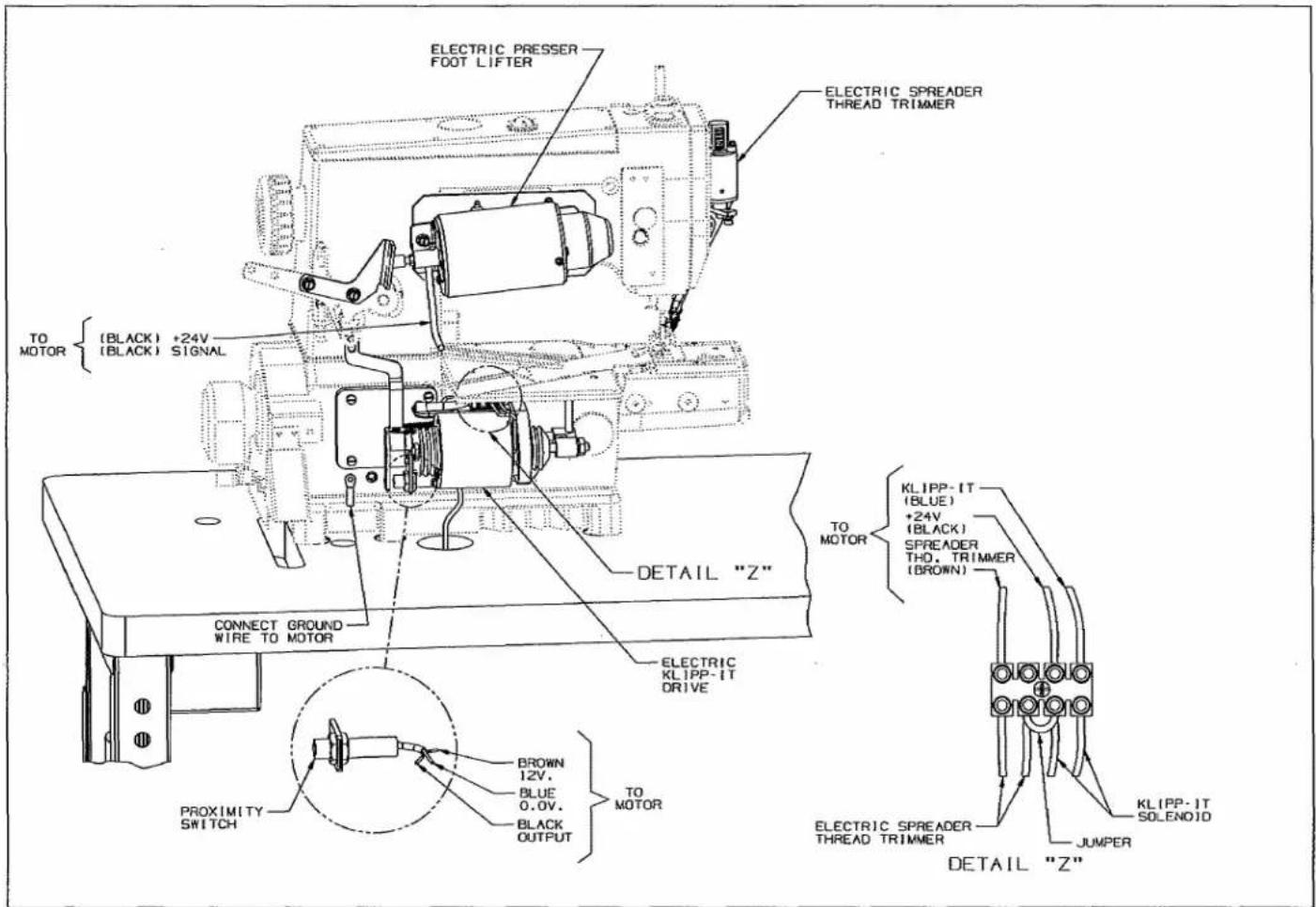
PRESSER FOOT LIFTER TO MOTOR {BLACK} +24V {BLACK} SIGNAL NEEDLE THREAD WIPER CONNECT GROUND WIRE TO MOTOR DETAIL "Z" ELECTRIC KLIPP-IT DRIVE PROXIMITY SWITCH BROWN 12V. BLUE 0.0V. BLACK OUTPUT TO MOTOR BROWN WHITE ELECTRIC NEEDLE THREAD WIPER JUMPER KLIPP-IT SOLENOID DETAIL "Z"UT2CS1
text_image
ELECTRIC PRESSER FOOT LIFTER ELECTRIC SPREADER THREAD TRIMMER TO MOTOR { (BLACK) +24V (BLACK) SIGNAL DETAIL "Z" CONNECT GROUND WIRE TO MOTOR ELECTRIC KLIPP-IT DRIVE BROWN 12V. BLUE 0.0V. BLACK OUTPUT TO MOTOR KLIPP-IT (BLUE) +24V (BLACK) SPREADER THO. TRIMMER (BROWN) ELECTRIC SPREADER THREAD TRIMMER JUMPER KLIPP-IT SOLENOID DETAIL "Z"UT3CS1
text_image
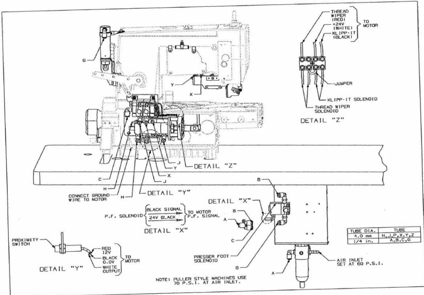
G Y X DETAIL "Z" X J C H H DETAIL "Y" P.F. SOLENOID {BLACK SIGNAL 24V BLACK} TO MOTOR P.F. SIGNAL DETAIL "X" PROXIMITY SWITCH DETAIL "Y" RED 12V BLACK 0.0V WHITE OUTPUT TO MOTOR PRESSER FOOT SOLENOID A B C DETAIL "X" JUMPER XLIPP-IT SOLENOID THREAD WIPER IREDI +24V (WHITE) XLIPP-IT (BLACK) TO MOTOR THREAD WIPER SOLENOID AIR INLET SET AT 60 P.S.I. NOTE: PULLER STYLE MACHINES USE 70 P.S.I. AT AIR INLET. TUBE DIA. TUBE 4.0 mm H, J, P, X, Y, Z 1/4 in. A, B, C, GUT4CS1
text_image
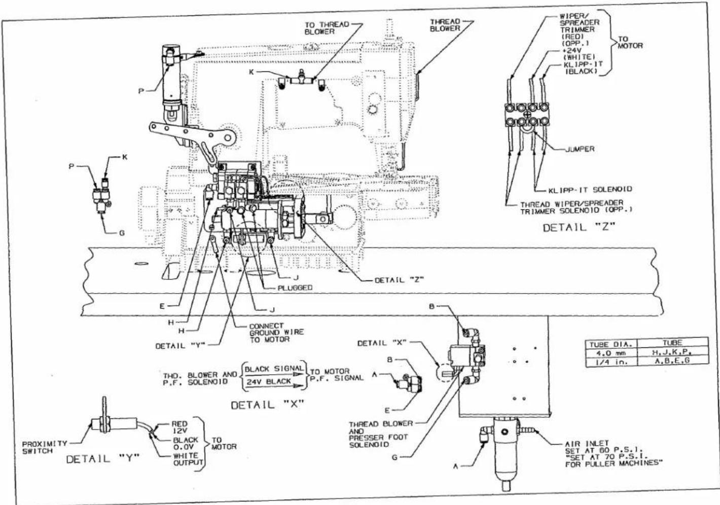
TO THREAD BLOWER THREAD BLOWER WIPER/SPREADER TRIMMER (RED) (OPP.) +24V (WHITE) KLIPP-IT (BLACK) TO MOTOR JUMPER KLIPP-IT SOLENOID THREAD WIPER/SPREADER TRIMMER SOLENOID (OPP.) DETAIL "Z" DETAIL "Z" PLUGGED DETAIL "Y" CONNECT GROUND WIRE TO MOTOR THD. BLOWER AND P.F. SOLENOID {BLACK SIGNAL 24V BLACK} TO MOTOR P.F. SIGNAL DETAIL "X" PROXIMITY SWITCH DETAIL "Y" RED 12V BLACK 0.0V WHITE OUTPUT TO MOTOR THREAD BLOWER AND PRESSER FOOT SOLENOID AIR INLET SET AT 60 P.S.I. "SET AT 70 P.S.I. FOR PULLER MACHINES" TUBE DIA. TUBE 4.0 mm H.J.K.P. 1/4 in. A.B.E.GUT5CS1
text_image
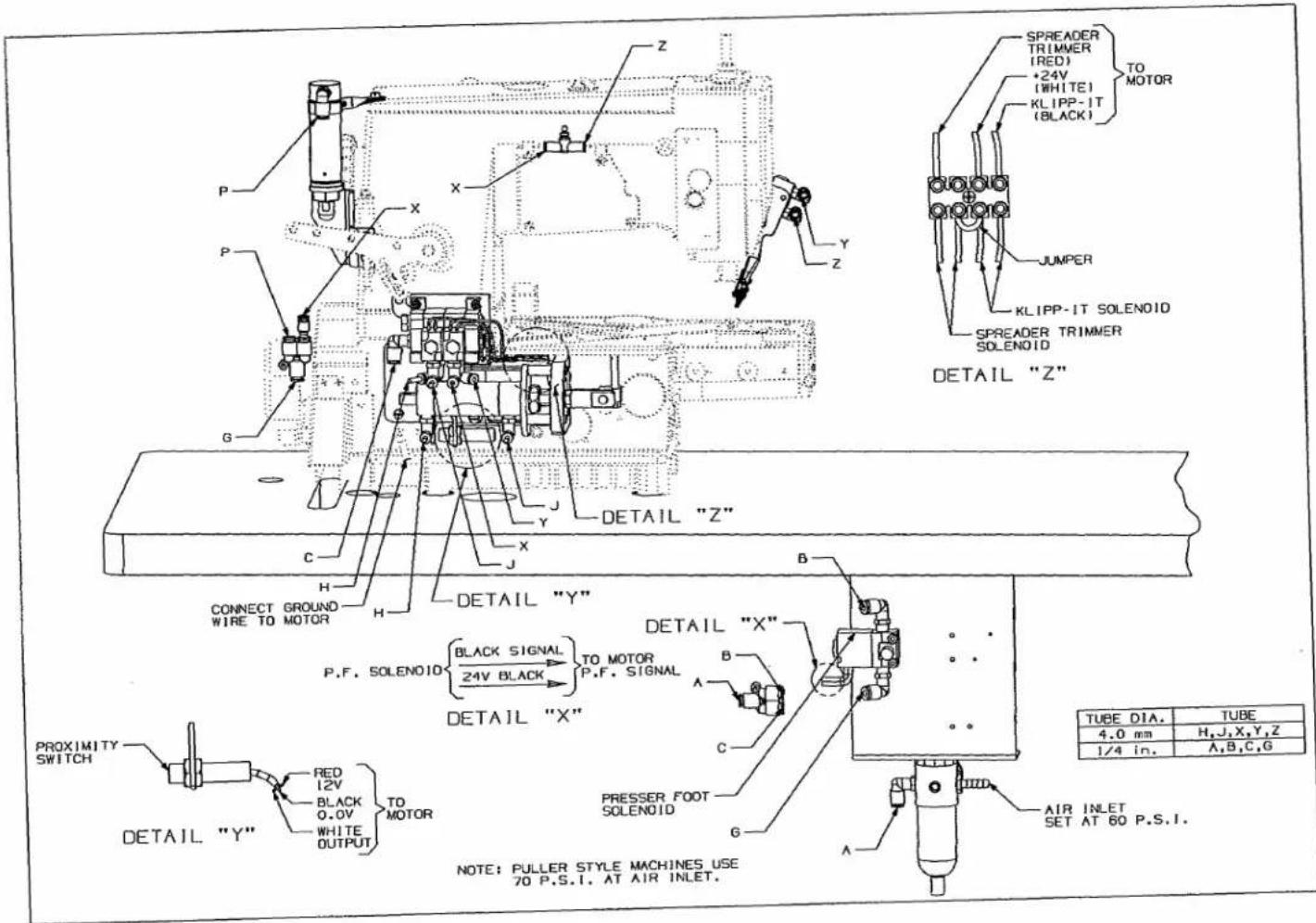
SPREADER TRIMMER (RED) +24V (WHITE) KLIPP-IT (BLACK) TO MOTOR JUMPER KLIPP-IT SOLENOID SPREADER TRIMMER SOLENOID DETAIL "Z" DETAIL "Z" X Y Z P X Y Z G C H H CONNECT GROUND WIRE TO MOTOR DETAIL "Y" P.F. SOLENOID BLACK SIGNAL 24V BLACK TO MOTOR P.F. SIGNAL DETAIL "X" B A C PROXIMITY SWITCH DETAIL "Y" RED 12V BLACK 0.0V WHITE OUTPUT TO MOTOR PRESSER FOOT SOLENOID G A NOTE: PULLER STYLE MACHINES USE 70 P.S.I. AT AIR INLET. AIR INLET SET AT 60 P.S.I. TUBE DIA. TUBE 4.0 mm H,J,X,Y,Z 1/4 in. A,B,C,GNOTES
NUMERICAL INDEX OF PARTS
| Part No. | Page No. | Part No. | Page No. | Part No. | Page No. |
| 1318001... | 29, 35 | 34762... | 29, 35 | 56392G... | 21 |
| 14076... | 29, 35 | 34763P... | 23 | 56392H... | 21 |
| 18-1449... | 23 | 34768A... | 23 | 56392L... | 21 |
| 18-1450... | 23 | 34768C... | 23 | 56392M... | 21 |
| 18-1453... | 23 | 34769B... | 23 | 57865... | 21 |
| 18-1472... | 23 | 34770LB... | 31 | 57892K... | 21 |
| 18-1473... | 23 | 34770M... | 23 | 6-878... | 35 |
| 18C1471... | 23 | 34773D... | 23 | 60078Z... | 31, 43 |
| 21233FB... | 35 | 34773E... | 23 | 660-1097... | 31, 43 |
| 22517A... | 29, 35 | 34773F... | 23 | 660-1099... | 39 |
| 22542... | 29 | 34775H... | 23 | 660-403... | 33 |
| 22569B... | 35 | 34794A... | 23 | 660-763... | 35 |
| 22569C... | 29 | 35086BJ... | 37 | 670E1302... | 29, 35 |
| 22585... | 29, 35 | 35086BK... | 37 | 670E673... | 33 |
| 22596... | 21 | 41358T... | 31 | 670E815... | 29, 35 |
| 22729... | 35 | 4611U... | 25 | 670G276... | 35 |
| 22735... | 21 | 50322AX... | 31 | 670K15... | 27 |
| 22738... | 31 | 50322AY... | 31 | 670K27... | 31 |
| 22738U... | 31 | 50332AB... | 27 | 670K28... | 29 |
| 22757... | 21 | 50332AD... | 23 | 670K29... | 25 |
| 22798A... | 31 | 50333B... | 25 | 671-103B... | 35 |
| 22848... | 31 | 50345Y... | 31 | 671-104A... | 35 |
| 22852A... | 29, 35 | 50347S... | 31 | 671-50... | 33 |
| 22894AX... | 35 | 50349C... | 31 | 671A360... | 39 |
| 28C... | 21 | 50358Y... | 21 | 671B182... | 35 |
| 29477NL... | 21 | 50362B... | 27, 37 | 671B23... | 33 |
| 29480ARF... | 23 | 50363BF... | 27, 37 | 671B81C... | 33 |
| 29480AST... | 33 | 50366D... | 23 | 671D42... | 33 |
| 29480ASU... | 33 | 50367H... | 25 | 671F81A... | 33, 35 |
| 29480ATW... | 35 | 50368AE... | 23 | 671F81C... | 33, 39 |
| 29480AWB... | 23 | 50372DG... | 31 | 671F82C... | 35 |
| 29480AXJ... | 39 | 50373DG... | 29, 35 | 671F86B... | 33 |
| 29906L... | 37 | 50374A... | 21 | 671F87... | 35 |
| 29906M... | 27 | 50382GY... | 31 | 671F88... | 33 |
| 29921C... | 39 | 50383AF... | 39 | 69H... | 31, 41 |
| 29921D... | 25 | 50383AR... | 39 | 77A... | 21 |
| 29980LB... | 43 | 50383N... | 35 | 80696RA... | 29, 35 |
| 29980LC... | 31 | 50383P... | 31 | 90... | 23 |
| 34382AC... | 23 | 50383R... | 31 | 90561K... | 33 |
| 34749P... | 23 | 50383S... | 25 | 92855A... | 25 |
| 34750P... | 23 | 50386A... | 31 | 95166V... | 31 |
| 34750R... | 23 | 50392AN... | 21 | 95167CV... | 37 |
| 34750SA... | 23 | 50392AP... | 21 | 95169... | 29 |
| 34750T... | 23 | 50392AR... | 21 | 95177... | 29 |
| 34750U... | 23 | 50392AS... | 21 | 95179K... | 29 |
| 34751MB... | 31 | 50392AV... | 21 | 95251... | 29 |
| 34751MC... | 31 | 50392R... | 21 | 95257... | 31 |
| 34751MD... | 31, 43 | 50392X... | 21 | 95259... | 31, 37 |
| 34751ME... | 31 | 50394AJ... | 41 | 95294... | 37 |
| 34751MF... | 31 | 50395M... | 31 | 95409D... | 31 |
| 34751MJ... | 31 | 50395N... | 25 | 95411... | 35 |
| 34751MK... | 31 | 50395P... | 25 | 95415... | 33 |
| 34751ML... | 31 | 50395R... | 25 | 95435A... | 31 |
| 34751MR... | 31 | 51250C... | 27, 37 | 95951... | 25 |
| 34751MS... | 23 | 51292F2... | 29, 35 | 95954... | 31, 35 |
| 34751MT... | 23 | 52336B... | 37 | 95956... | 37 |
| 34752M... | 23 | 53636C... | 25 | 96150... | 27, 37 |
| 34752N... | 23 | 55235E... | 29, 35 | 96161... | 27, 37 |
NUMERICAL INDEX OF PARTS
| Part No. | Page No. | Part No. | Page No. |
| 96261... | 29,35 | NS6120310SP... | 39 |
| 96280... | 27,37 | NS6150430SP... | 25 |
| 96711... | 21 | NS6660430SP... | 25 |
| 96721... | 29,35 | PH0300083UO... | 27,37 |
| 96721A... | 27 | RE025000KO... | 23 |
| 99296... | 21 | RM2724A... | 33 |
| 99327... | 35 | RM2871B... | 35 |
| 99358... | 27,37 | SD0600176SP... | 23 |
| 995-705AS... | 31 | SM6020250TP... | 23 |
| 99545F... | 37 | SM6020600TP... | 23 |
| 99545G... | 27,37 | SM6021000TP... | 23 |
| 99545G99646J... | 27 | SN1020450TP... | 23 |
| 99545H... | 27,37 | SS4051281SE... | 25 |
| 99591DH... | 35 | SS4091015SP... | 27,37 |
| 99591DN... | 27,37 | SS4110715SP... | 25 |
| 99591DP... | 27 | SS4120615SP... | 41 |
| 99613D... | 29,35 | SS4121015SP... | 39 |
| 99614D... | 29,35 | SS4121215SP... | 39 |
| 99615... | 29,35 | SS4121415SA... | 31 |
| 99616... | 29 | SS4121415SP... | 35 |
| 99616A... | 35 | SS6060210SP... | 27,37 |
| 99617A... | 29 | SS6060510TP... | 27,37 |
| 99617T... | 35 | SS6080610TP... | 37 |
| 99619... | 29,35 | SS6110710TP... | 25 |
| 99620... | 21 | SS6122030SP... | 39 |
| 99646J... | 27,37 | SS7090510SP... | 27 |
| 99650D... | 27,37 | SS7090520SP... | 21 |
| 99650E... | 27 | SS7090610SP... | 27,37 |
| 99652A... | 37 | SS7091110SP... | 27 |
| 99653B... | 27,37 | SS9111010SP... | 25 |
| 99653C... | 27 | SS9120910TP... | 27,37 |
| 99657E... | 27,37 | SS9151420TP... | 25 |
| 99683CP... | 33 | WS0510002KP... | 25,39 |
| 99683VG... | 43 | WS0631510KP... | 25 |
| 99694A... | 35 | ||
| 99697AA... | 27,37 | ||
| 99733... | 29 | ||
| 998-297A... | 29,35 | ||
| 998-306B... | 29 | ||
| 998-358E... | 29,31,35 | ||
| 999-191H... | 37 | ||
| 999-411-M5-4... | 37 | ||
| A9858... | 21 | ||
| B3021804010... | 21 | ||
| B3101804000... | 21 | ||
| B3103804000... | 21 | ||
| B3112704000... | 21 | ||
| B3120352000... | 21 | ||
| B3120704000... | 21 | ||
| B3121804000... | 21 | ||
| B3126012000... | 21 | ||
| G21233BG... | 29 | ||
| G51346KA... | 21 | ||
| G52882KW... | 29,35 | ||
| GAK33034000... | 25 | ||
| GAK3303600A... | 25 | ||
| GAK8403000A... | 25 | ||
| NS6110420SP... | 21 |

natural_image
World map projection with latitude and longitude grid lines (no text or labels)WORLDWIDE SALES AND SERVICE
Union Special Corporation maintains sales and service facilities throughout the world. These offices will aid you in the selection of the right sewing equipment for your particular operation. Union Special Corporation representatives and service technicians are factory trained and are able to serve your needs promptly and efficiently. Whatever your location, there is a qualified representative to serve you.
Corporate Office:
One Union Special Plaza Huntley, IL 60142 Phone: 847•669•5101 Fax: 847•669•4454
European Distribution Center:
Union Special GmbH Raiffeisenstrasse 3 D-71696 Möglingen, Germany Tel: 49•07141•247•0 Fax: 49•07141•247•100
Brussels, Belgium
Charlotte, N.C.
El Paso, TX
Hong Kong, China
Huntley, IL
Leicester, England
Lille, France
Miami, FL
Milan, Italy
Möglingen, Germany
Montreal, Quebec
Osaka, Japan
Santa Fe Springs, CA
Other Representatives throughout all parts of the world.

Union Special® INDUSTRIAL SEWING EQUIPMENT