LF612K100MP - Sewing machine Union Special - Free user manual and instructions
Find the device manual for free LF612K100MP Union Special in PDF.

User questions about LF612K100MP Union Special
0 question about this device. Answer the ones you know or ask your own.
Ask a new question about this device
Download the instructions for your Sewing machine in PDF format for free! Find your manual LF612K100MP - Union Special and take your electronic device back in hand. On this page are published all the documents necessary for the use of your device. LF612K100MP by Union Special.
USER MANUAL LF612K100MP Union Special
Adjusting instructions and illustrated parts list
natural_image
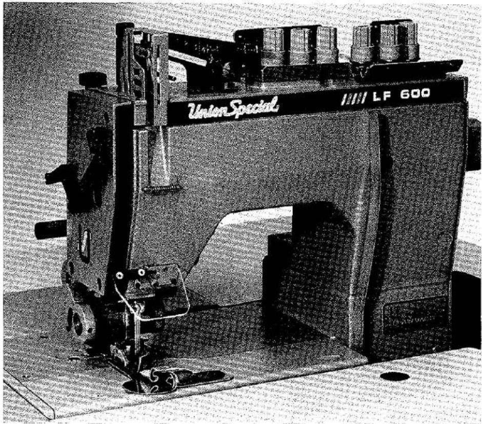
Black-and-white photo of a Union Special LF 600 machine with no visible text or symbols on the device itself.Two- and Three-needle, LF600 "Standard Class" plain feed flatbed machines.

natural_image
Abstract black and white geometric shape resembling a stylized letter 'U' with no text or symbolsFinest Quality
Union Special®
Industrial Sewing Equipment
FOREWORD
This technical manual has been prepared to guide you in the maintenance of your new UNION SPECIAL machine. Careful attention to the instructions for operating and adjusting these machines will enable you to maintain the superior performance and reliability designed and built into every UNION SPECIAL machine.
The Adjusting Instruction portion of this manual explains in detail the proper setting for each of the components related to forming the stitch and completing the functions of the machine. Figures are used to illustrate the adjustments using reference letters to point out specific items discussed.
Adjustments are presented in sequence so that a logical progression is accomplished. Some adjustments performed out of sequence may have an adverse effect on the function of other related parts.
Implementation of Preventive Maintenance Schedule can bring about significant improvements in operator productivity by avoiding costly equipment breakdowns. Whenever it becomes necessary to make repairs or replace parts on your machine, be sure to insist on genuine UNION SPECIAL Repair Parts. These parts are designed specifically for your machine and manufactured with utmost precision to assure long lasting service.
This Catalog has been made on the basis of available information. Changes in design and/or improvements may incorporate a slight modification of configuration in illustrations or part numbers.
CATALOG NO. 143 N
| For Styles | |
| LF612K100HB | LF612K101MBE |
| LF612K100HC | LF612K112HJ |
| LF612K100HJ | LF613K100HJ |
| LF612K100HR | LF613K100HR |
| LF612K100MP | LF613K101HR |
| LF612K100MX | LF613K112HR |
First Edition
Copyright 1990
By
Union Special Corporation
Rights Reserved In All Countries
Printed in U.S.A.
July, 1990
Each UNION SPECIAL machine is identified by a Style number, which on this machine Class, is stamped into the Style plate affixed to the right front of machine. Serial number is stamped into bed casting at the left rear base of machine
NOTE: Instructions stating direction or location, such as right, left, front or rear of machine, are given relative to the operator's position at the machine, unless otherwise noted. The handwheel rotates counterclockwise in operating direction as viewed from the right end of machine.
STYLES OF MACHINES
High speed, maximum performance, double locked stitch, plain feed flatbed machine. Totally enclosed feed and looper drive mechanism, fully automatic forced feed lubricating system with easily replaceable oil filter, quick stitch change, independently driven rear needle guard and quick adjustable looper avoid.
| LF612K100HB | Two needle, HIGH capacity, for seaming trousers and similar garments made of medium heavy to heavy weight material. Right needle in front. Standard recommended needle Type 128 GBS, Size 100/040. Available in 7 S.P.I. ONLY. Standard gauge No. 1 ONLY. The seam produced has two rows of stitching with the strength of 14 S.P.I., yet the fabric is moved forward at a rate of 7 S.P.I. Maximum recommended speed 6500 R.P.M., depending on operation. |
| LF612K100HC | Same as Style LF612K100HB except available in 10 S.P.I. ONLY. |
| LF612K100HJ | Two needle, HIGH capacity, for attaching risers to dungarees, piecing sleeves on denim jackets and attaching overall bibs. Includes double lap seam folder 3/32 inch (2.4mm) capacity. Left needle in front. Standard recommended needle Type 128 GAS, Size 125/049. Stitch range 7-14 S.P.I. Standard gauge Nos. 16 and 18. Maximum recommended speed 6500 R.P.M., depending on operation. |
| LF612K100HR | Same as Style LF612K100HJ except Standard gauge No. 18 ONLY. Stitch range 7-10 S.P.I. |
| LF612K100MP | Two needle, MEDIUM capacity, for piecing sleeves, joining shoulders and setting sleeves on ordinary quality shirts made with light to medium weight materials. Includes double lap seam folder 1/16 inch (1.6mm) capacity. Standard recommended needle Type 192 GLS, Size 75/029. Stitch range 9-20 S.P.I. Standard gauge Nos. 12 and 16. Maximum recommended speed 6500 R.P.M., depending on operation. |
| LF612K100MX | Two needle, MEDIUM capacity for quilting collar bands of shirts and similar garments. Standard recommended needle Type 192 GLS, Size 90/036. Stitch range 14-20 S.P.I. Standard gauge No. 24 ONLY. Maximum recommended speed 6500 R.P.M., depending on operation. |
| LF612K101MBE | Two needle, MEDIUM capacity, for hemming bloomers. Equipped with Close-Coupled Roller Puller. Standard recommended needle Type 192 GLS, Size 80/032. Stitch range 6-12 S.P.I. Standard gauge No. 16 ONLY. Maximum recommended speed 6500 R.P.M., depending on operation. |
| LF612K112HJ | Same as Style LF612K100HJ except - equipped with power "AIR-KLIPP"® Chain Cutter. Standard recommended needle Type 128 GAS, 125/049. |
| LF613K100HJ | Three needle, HIGH capacity, for seaming wind breakers, mackinaws, lumber jacks and for similar operations on medium heavy to heavy weight material. Equipped with tractortype presser foot. Includes double lap seam folder 3/32 inch (2.4mm) capacity. Standard recommended needle Type 128 GAS, Size 125/049. Stitch range 7-10 S.P.I. Standard gauge Nos. 8 and 9. Maximum recommended speed 6500 R.P.M., depending on operation. |
| LF613K100HR | Three needle, HIGH capacity, for seaming sanforized denim and similar operations on medium to heavy weight materials. Includes double lap seam folder 1/8 inch (3.2mm) capacity. Standard recommended needle Type 128 GAS, Size 125/049. Stitch range 7-14 S.P.I. Standard gauge Nos. 8 and 9. Maximum recommended speed 6500 R.P.M., depending on operation. |
| LF613K101HR | Three needle, HIGH capacity, for seaming sanforized denim and similar operations. Equipped with Close-Coupled Roller Puller. Includes double lap seam folder. 1/8 inch (3.2mm) capacity. Standard recommended needle Type 128 GAS, Size 125/049. Stitch range 7-10 S.P.I. Standard gauge Nos. 8 and 9. Maximum recommended speed 6500 R.P.M., depending on operation. |
| LF613K112HR | Same as Style LF613K100HR except -equipped with power "AIR-KLIPP®" Chain Cutter. |
®"AIR-KLIPP" is a registered trademark of Union Special Corporation.
SAFETY RULES

CAUTION!
THIS SYMBOL INDICATES YOUR PERSONAL SAFETY IS INVOLVED
TO PREVENT PERSONAL INJURY:
— All power sources to the machine MUST be TURNED OFF before threading, oiling, adjusting, or replacing parts.
— Wear safety glasses.
— All shields and guards MUST be in position before operating machine.
— DO NOT tamper with safety shields, guards, etc., while machine is in operation.
LUBRICATION
IMPORTANT: Machine must be in a leveled position.
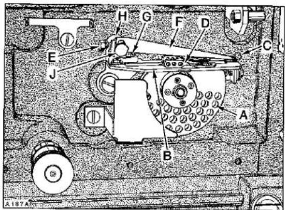
Oil has been drained from main reservoir before shipment. Use a straight mineral oil with a Saybolt viscosity of 90 to 125 seconds at 100^ Fahrenheit. This is equivalent to UNION SPECIAL Specification No. 175. Remove oil filler cap (A, Fig. 1) and fill to the TOP line of oil level gauge (B). Replace oil filler cap.
CAUTION! On new machines, machines that have been out of service for an extended period of time OR machines that have been drained of oil and refilled .... RUN MACHINE SLOWLY at 300 R.P.M. for approximately five minutes while paying strict attention to the oil flow indicator which should rise in the oil filler cap (A) and remain steady while machine is running. This must be noted to ensure that oil flow indicator is functioning and oil is circulating. Check oil level while machine is running which MUST be maintained between the red lines of oil level gauge.
To maintain maximum recommended speed and serviceability of these machines, refer to General-Preventive Maintenance Schedule. Under no circumstances, should oil remain in the machine for more than one year. Oil drain plug is located in bottom of oil pan. ALWAYS change oil filter when oil is changed. At this time, evaluate the contaminated condition of the oil to determine if the oil filter should be changed more or less frequently. To replace filter, remove four screws (C, Fig. 1) and cover (D); lift out filter cartridge. REMOVE (brass) BY-PASS VALVE FROM TOP OF OLD FILTER AND INSTALL IN NEW FILTER. Reassemble in reverse manner.
LUBRICATION DIAGRAM

text_image
Technical schematic diagram of an electrical device with labeled components A, B, C, and D
PRESSURE OIL

SIPHON RETURN

INLET

FILTER BY-PASS
P100B
Fig. 1
NEEDLES
Each needle has both a type and size number. Type number denotes the kind of shank, point, length, groove, finish, and other details. Size number, stamped on the needle shank in metric, denotes largest diameter of blade, measured midway between shank and eye. Collectively, type and size number represent the complete symbol, which is given on the label of all needles packaged and sold by UNION SPECIAL CORPORATION.
The type numbers of the needles recommended for each Style of machine covered by this catalog are given in the machine style description. Other needles are available, but the ones indicated are those recommended to produce the most satisfactory results. The type numbers of the recommended needles together with their descriptions, and the sizes available are listed below:
| NEEDLE TYPE | DESCRIPTION | SIZES AVAILABLE |
| 128 GAS | Round shank, round point, short, double groove, struck groove, ball eye, spotted, chromium plated. | 80/032, 90/036, 100/040, 110/044, 125/049, 140/054, 150/060, 170/067. |
| 128 GBS | Round shank, round point, short, double groove, struck groove, ball eye, spotted, ball point, chromium plated. | 80/032, 90/036, 100/040, 10/044, 125/049, 140/054, 150/060. |
| 192 GLS | Round shank, round point, extra short, double groove, struck groove, ball eye, spotted (plated) thin ball point, chromium. | 55/022, 65/025, 70/027, 75/029, 80/032, 90/036. |
To have needle orders promptly and accurately filled, an empty package, a sample needle, or the Type and Size number should be forwarded. Use description on label. A complete order would read "1000 needles, Type 128 GBS, Size 90/036".
NOTE: On earlier styles, machines equipped with a DURACOAT ALUMINUM needle bar, TORQUE needle bar connection screw, 16 to 18 in-lbs (18.4 to 20.7 cm/kg).
On later styles, machines equipped with a STEEL needle bar, TORQUE needle bar connection screw, 22 to 25 in-lbs (25.3 to 28.8 cm/kg).
THREAD MACHINE AS ILLUSTRATED.

text_image
PIVOT GUARD TO LEFT FOR THREADING For ease of threading, pull lever down and push looper holder to the right. CAUTION! Looper holder MUST be returned to extreme left and LOCKED by pulling release lever up before sewing. Three Thread TWO THREADA193A
THREADING DIAGRAM
TIMING FEED TO NEEDLE
Adjustment would be required if the machine is feeding while the needles are in the work.
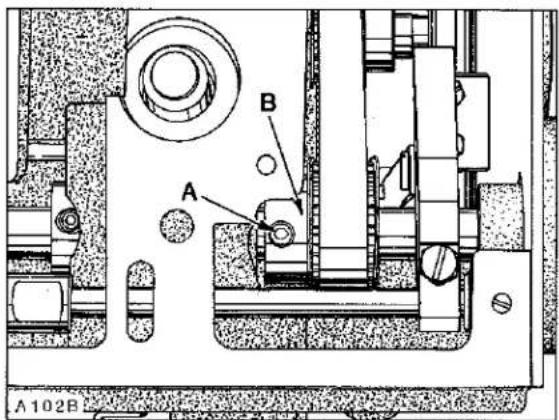
This can be accomplished by removing top cover, head cover, left cloth plate, and top feed chamber cover. Rotate handwheel in operating direction to position needle bar at bottom of stroke. At this time, the first screw (A, Fig. 2) in the feed drive eccentric (B) must be on the flat of the feed drive shaft and in a vertical position. Adjustment can be made by loosening two screws (A, Fig. 3) in upper mainshaft sprocket (B). Hold the handwheel firmly with needle bar at bottom of stroke and rotate pulley as required to position screw (A, Fig. 2) so it is vertical. Torque screws (A, Fig. 3) to 55 in-lbs. (63 cm/kg).
NOTE: Whenever "TIMING FEED TO NEEDLE" is corrected, always check "SYNCHRONIZING LOOPER AND NEEDLE MOTIONS."
SYNCHRONIZING LOOPER AND NEEDLE MOTIONS
NOTE: End cover has been removed for clarity in Figure 4, but MUST BE IN POSITION WHILE MAKING THE FOLLOWING ADJUSTMENTS.
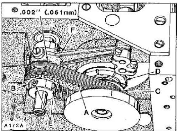
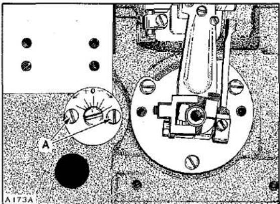
Looper drive belt, (A, Fig. 4) has proper tension if, when turning handwheel in operating direction to position looper in the center of its (right to left) travel..... there is no noticeable (right to left) play in the looper mechanism. There should be approximately 1/8 inch (3.2mm) deflection in looper drive belt when pressing firmly with thumb, midway between sprockets (B and C). Adjustment can be made by loosening two screws (A, Fig. 5) and turn looper module (D, Fig. 4) counterclockwise to tighten belt or clockwise to loosen, as viewed in Figure 4. Retighten screws (A, Fig. 5).
To synchronize machine, remove needle bar eyelet guard, needle thread take-up cam wire, needles, presser foot, throat plate, loopers, and feed dog. Turn handwheel to position needle bar at BOTTOM of stroke and looper holder at EXTREME right end of travel.

natural_image
Mechanical assembly diagram showing a cam mechanism with labeled parts A and B (no readable text or symbols)Fig.2
text_image
A B A 102BFig.3
text_image
.002" (.051mm) F B A E C D A172AFig.4
text_image
A F0 A173AFig.5
SYNCHRONIZING LOOPER AND NEEDLE MOTIONS (Continued)
Using gauge No. 21227 AC, mount gauge plate with throat plate attaching screws. Insert pin (included with gauge) into looper holder. Mount indicator block to machine head
with one of the screws removed from needle bar eyelet guard. Insert shank of indicator gauge into indicator block and tighten screw against shank. (See Sketch A for reference).

natural_image
Technical line drawing of a mechanical assembly with no visible text or symbolsSketch A
NOTE: For Style LF612K101MBE use 21227 T mounting plate.
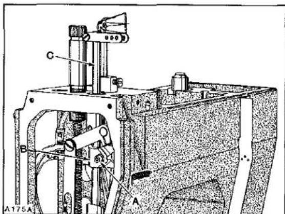
Rotate handwheel in OPERATING direction until the pin in looper holder contacts gauge plate. Loosen screw (A, Fig. 6) in needle bar connection (B) and position needle bar (C) as required to set the pointer of indicator gauge at "O" and tighten screw (A) VERY LIGHTLY.
IMPORTANT: Refer to NOTE, page 7 for proper TORQUE of screw.
text_image
C B A A175AFig.6
Rotate handwheel in REVERSE direction until pin in looper holder again makes contact with gauge plate and note the reading on the gauge. A variation of (1) graduation on the scale is permissible. If the reading is above "O", loosen screws (E, Fig. 4) and turn rear looper drive sprocket (B) towards the operator (clockwise as viewed in Figure 4). If the reading is below "O", turn sprocket away from operator (counterclockwise as viewed in Figure 4). Temporarily snug screws.
Rotate handwheel in OPERATING direction until pin in looper holder contacts gauge plate and note the reading on scale. If the reading is above "O", loosen screws (E) and turn sprocket (B) away from operator (counterclockwise as viewed in Figure 4). If the reading is below "O", turn sprocket towards the operator (clockwise as viewed in Figure 4). Temporarily snug screws.
SYNCHRONIZING LOOPER AND NEEDLE MOTIONS (Continued)
Continue to check and adjust in both OPERATING and REVERSE directions until pointer of indicator gauge comes within (1) graduation on the scale when turning the handwheel in either direction.
Before tightening screws (E) securely, be sure to have .002 inch (.051mm) clearance between sprocket (B) and needle guard drive connecting rod (F).
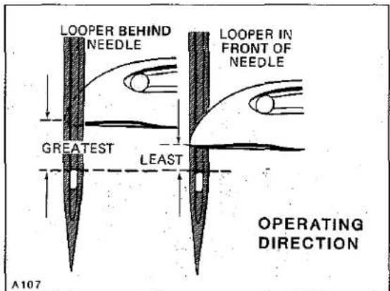
If a synchronizing gauge is not available.... turn the handwheel in operating direction to position right looper point even with the left side of right needle and check the distance from the eye of needle to the bottom of looper blade.
Turn handwheel in reverse direction to position looper point even with the left side of RIGHT needle and check the distance from the eye of needle to the bottom of looper blade. If the distance was greater when handwheel was turned in operating direction, (as viewed in Sketch B) loosen screws (E, Fig. 4) and turn rear looper drive sprocket (B) away from operator (counterclockwise as viewed in Figure 4). If the distance was greater when handwheel was turned in reverse direction, (as viewed in Sketch C) turn sprocket towards the operator (clockwise as viewed in Figure 4). Temporarily snug screws.
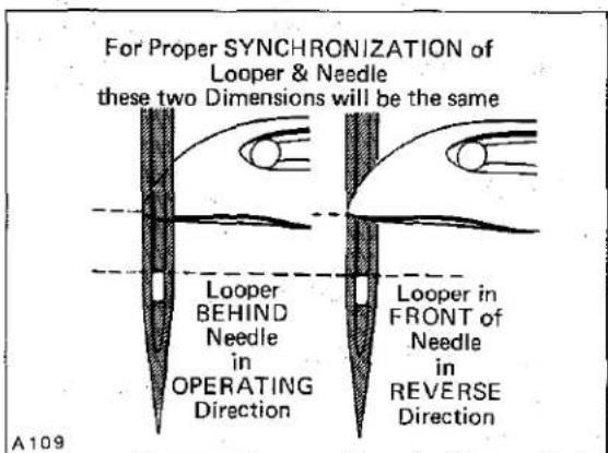
Continue to check and adjust in both OPERATING and REVERSE directions until the distance from the eye of the RIGHT needle to the bottom of looper blade is the same in either direction, (as viewed in Sketch D).
Before tightening screws (E, fig. 4) securely, be sure to have .002 inch (.051mm) clearance between sprocket (B) and needle guard drive connecting rod (F).
text_image
LOOPER BEHIND NEEDLE LOOPER IN FRONT OF NEEDLE GREATEST LEAST OPERATING DIRECTION A107Sketch B

text_image
LOOPER BEHIND NEEDLE LEAST GREATEST LOOPER IN FRONT OF NEEDLE A108 REVERSE DIRECTIONSketch C
text_image
For Proper SYNCHRONIZATION of Looper & Needle these two Dimensions will be the same Looper BEHIND Needle in OPERATING Direction Looper in FRONT of Needle in REVERSE Direction A109Sketch D
text_image
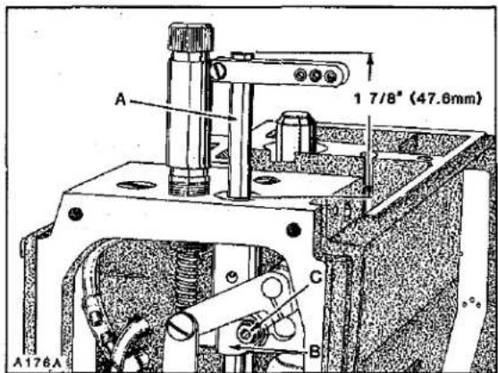
A 1 7/8" (47.6mm) C B A176AFig.7
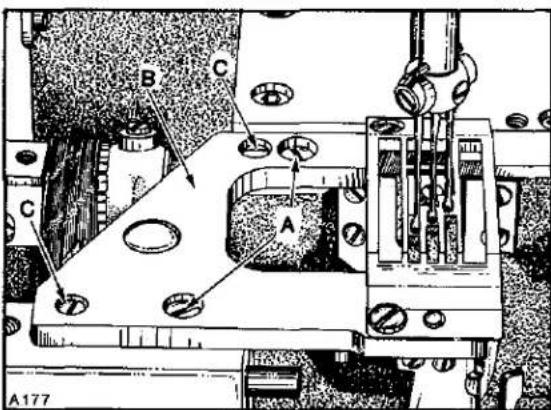
Rotate handwheel to ensure that needles center in the needle holes of throat plate as shown in Figure 8. Adjustment can be made by loosening screw (C, Fig. 7) slightly, allowing needle bar to be rotated as required, while being careful to maintain the temporary height setting and tighten screw (C) AS SPECIFIED. An additional 4-way directional adjustment of the throat plate can be accomplished as follows:
text_image
A B C D +0 A176AFig.9
CAUTION! DO NOT wedge or pry with any type of tool, as damage to needle bar may result.
LOOPER SETTINGS
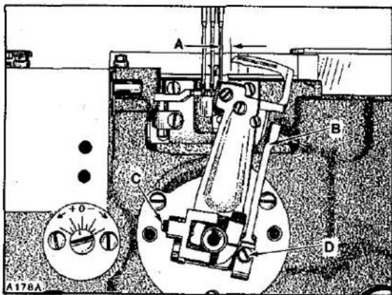
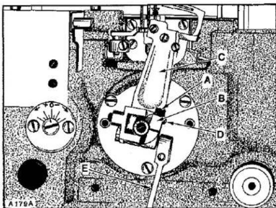
If not previously done, insert a new set of needles; type and size specified. With looper holder at EXTREME right end of travel, distance from centerline of RIGHT needle to point of RIGHT looper should be dimension (A, Fig. 9); see chart. Adjustment can be made by pulling release lever (B) down and loosening screw (A, Fig. 10) in stop collar (B). Apply pressure against the upper portion of looper
NEEDLE BAR ALIGNMENT
Insert a new set of needles. As a temporary setting, the TOP of needle bar (A, Fig. 7) should be approximately 1 7/8 inches (47.6mm) from the TOP of upper needle bar bushing when needle bar connection (B) is positioned at TOP of STROKE as shown in Figure 7. Adjustment can be made by loosening screw (C), reposition needle bar up or down as required and tighten screw (C) VERY LIGHTLY.
IMPORTANT: Refer to NOTE, page 7 for proper TORQUE of screw.
text_image
A177 B C AFig.8
IMPORTANT: Adjustment of throat plate must be coordinated between needles and feed dog; refer to "FEED DOG SETTINGS". Loosen two screws (A, Fig. 8) in throat plate support (B). Loosen two screws (C) which secure locating ferrules, allowing the throat plate support to be repositioned slightly. Tighten screws (C) first, then screws (A).
text_image
A179A C A B D EFig.10
LOOPER SETTINGS (Continued)
holder (C) to the LEFT while turning screw (D) in looper holder clockwise to increase looper gauge or counterclockwise to decrease. Applicable looper gauge can be used advantageously in making this adjustment. Continue to apply pressure against upper portion of looper to the LEFT while turning stop collar (B) to its EXTREME CLOCKWISE position and tighten screw (A) securely. Push up release lever (E) to lock looper holder in position. Adjust screw (C, Fig. 9) which incorporates a spring plunger, against the recess in cam of stop collar as required to attain the following conditions:
Pull release lever down and be able to push looper holder to the right, with a snapping motion (making loopers easily accessible for threading). Push looper holder to the left, with a snapping motion. Apply pressure against upper portion of looper holder to the LEFT and push release lever up to lock looper holder in operating position.
In locked position, the release lever should be approximately in line with middle looper as viewed from the right side of looper holder. Adjustment can be made by loosening screw (D, Fig. 9), reposition release lever as required and retighten screw.
Loopers must also be set so, as they travel to the left behind the needles, NOT to touch, but with a MAXIMUM clearance of .002 inch (.051mm). Adjustment can be made by pulling release lever down, loosening screw (A, Fig. 10) in stop collar (B) allowing looper holder to be moved forward or rearward on its shaft, as required. Apply pressure against upper portion of looper holder to the LEFT while turning stop collar (B) to its EXTREME CLOCKWISE position and tighten screw (A) securely and push release lever up in locking position. RECHECK looper gauge.
| MACHINE STYLE | DIMENSION A FIG. 9 | LOOPER GAUGE NO. |
| LF612K100HB-1 | 5/32 inch (4.0mm) | 21225-5/32 |
| LF612K100HC-1 | 5/32 inch (4.0mm) | 21225-5/32 |
| LF612K100HJ-16 | 5/32 inch (4.0mm) | 21225-5/32 |
| LF612K100HJ-18 | 5/32 inch (4.0mm) | 21225-5/32 |
| LF612K112HJ-16 | 5/32 inch (4.0mm) | 21225-5/32 |
| LF612K112HJ-18 | 5/32 inch (4.0mm) | 21225-5/32 |
| LF612K100HR-18 | 5/32 inch (4.0mm) | 21225-5/32 |
| LF612K100MP-12 | 1/8 inch (3.2mm) | 21225-1/8 |
| LF612K100MP-16 | 1/8 inch (3.2mm) | 21225-1/8 |
| LF612K100MX-24 | 1/8 inch (3.2mm) | 21225-1/8 |
| LF612K101MBE-16 | 1/8 inch (3.2mm) | 21225-1/8 |
| LF613K100HJ-8 | 5/32 inch (4.0mm) | 21225-5/32 |
| LF613K100HJ-9 | 5/32 inch (4.0mm) | 21225-5/32 |
| LF613K100HR-8 | 5/32 inch (4.0mm) | 21225-5/32 |
| LF613K100HR-9 | 5/32 inch (4.0mm) | 21225-5/32 |
| LF613K101HR-8 | 5/32 inch (4.0mm) | 21225-5/32 |
| LF613K101HR-9 | 5/32 inch (4.0mm) | 21225-5/32 |
| LF613K112HR-8 | 5/32 inch (4.0mm) | 21225-5/32 |
| LF613K112HR-9 | 5/32 inch (4.0mm) | 21225-5/32 |

text_image
1/64" (0.4mm) A180A B AFig.11
NEEDLE BAR HEIGHT
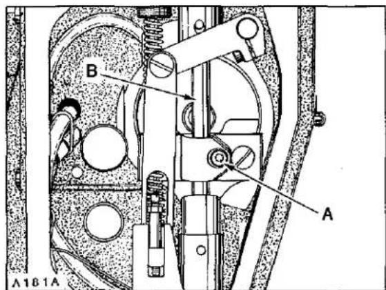
Turn handwheel in operating direction until POINT of RIGHT looper (A, Fig. 11) is even with the LEFT side of RIGHT needle (B). TOP of needle eye should be 1/64 inch (.4mm) below the undersurface of looper blade, as shown in Figure 11. Adjustment can be made by loosening screw (A, Fig. 12) and move needle bar (B) up or down as required. TORQUE screw (A).
IMPORTANT: Refer to NOTE, page 7 for proper TORQUE of screw. Care must be taken not to disturb ALIGNMENT of needle bar while making this adjustment.
NOTE: DO NOT wedge with any type of tool, as damage to needle bar may result.
text_image
A B A A181AFig.12
LOOPER AVOID
Machine is equipped with a quick adjustable looper avoid mechanism to accommodate extreme differences in needle sizes. As the looper travles from left to right with needle bar descending, the needle points should contact ONLY the lower THIRD of the back of looper blades. If looper avoid requires re-setting, loosen two screws (A, Fig. 13) and turn eccentric stud (B) towards the plus side (counterclockwise) for MORE looper avoid or towards the minus side (clockwise) for LESS looper avoid. When desired setting is acquired, tighten screws (A).
NOTE: Whenever looper avoid is changed, always recheck "LOOPER SETTINGS".

text_image
A182A B C D EFig.13
REAR NEEDLE GUARD TIMING AND ADJUSTMENT
Rotate handwheel in operating direction to position looper points at the RIGHT hand side of needles. At this time the needle guard (C, Fig. 13) should be at its EXTREME END of FORWARD travel. Adjustment can be made by loosening two screws (A, Fig. 14) and turn needle guard eccentric (B) slightly as required until this condition exists. Ensure .002 inch (.051mm) clearance between needle guard eccentric (B) and looper drive sprocket (C) while tightening screws (A) securely.
REAR NEEDLE GUARD TIMING AND ADJUSTMENT(Continued)
At extreme forward end of travel, rear needle guard (C, Fig. 13) must be set horizontally not to contact needles (D) with a MAXIMUM clearance of .002 inch (.051mm). Guard should be set as low as possible, yet have its vertical face approach approximately 3/64 inch (1.2mm) of needle points until point of loopers moving to the left, are even with the right side of needles. Adjustment can be made by loosening screw (E), reposition needle guard as required and retighten screw.
If additional front to rear adjustment is required to maintain needle guard in a horizontal position, loosen screw (D, Fig. 14) in pivot link which allows needle guard shaft to be rotated. Be sure to take up thrust, by exerting pressure against needle guard holder to the left and pivot link to the right, when tightening screw (D).
NOTE: Change in stitch length WILL NOT require change in needle guard setting, but a change of needle SIZE, may.
FEED DOG SETTINGS
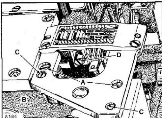
Feed dog should be centered in throat plate with equal clearance on both sides and ends. Feed dog should be level with and parallel to the top of throat plate as it begins to rise. At highest point of travel, feed dog teeth should extend the depth of a full tooth, or approximately 3/64 inch (1.2mm) above throat plate. MINOR (right to left) adjustments can be made by loosening two screws (A, Fig. 15) in throat plate support (B). Loosen two screws (C) securing two locating ferrules which allow movement to align throat plate support. Reposition slightly as required, considering both needle hole slots and feed dog slots. Tighten screws (C) first, then screws (A). Front to rear adjustment can be made by turning stitch regulating knob (A, Fig. 16) counterclockwise to obtain LONGEST stitch length. Remove rear feed chamber cover which is secured with four screws.

text_image
A183A C B A(2) DFig.14
text_image
A184 C D A B CFig.15

text_image
10 9 8 A A114Fig.16

text_image
A B A115AFig.17
FEED DOG SETTINGS (Continued)
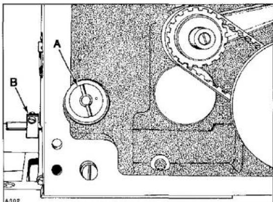
Loosen Allen screw (A, Fig. 17) and turn eccentric (B) while rotating handwheel in operating direction to obtain equal clearance in throat plate, front and rear. Tighten screw (A) securely.
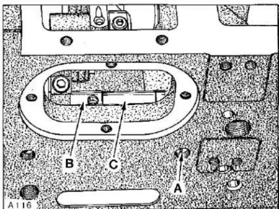
Feed dog can be leveled or tilted by loosening screw (A, Fig. 18) and rotate feed rocker tilting shaft (A, Fig. 19) slightly as required. Punch mark on shaft must be facing operator. Check parallelism of feed dog by placing throat plate in position. Before tightening screw (A, Fig. 18), make sure to have approximately .002 inch (.051mm) clearance between feed rocker (B) and spacer sleeve (C).
text_image
A116 B C AFig.18
IMPORTANT: Recheck front to rear clearance of feed dog in throat plate slots whenever feed rocker tilting shaft has been repositioned. Replace rear feed chamber cover.
With feed travel set to desired stitch length, set feed dog height as specified by loosening mounting screw (D, Fig. 15) to position as required. Feed dog supporting screw is located in the feed dog holder, adjust as required to support feed dog before tightening screw (D).
text_image
A B A002Fig.19
CHANGING STITCH LENGTH
Stitch length is changed by turning stitch regulating knob (A, Fig. 16) clockwise to shorten the stitch or counterclockwise to lengthen the stitch. Recheck front to rear clearance under "FEED DOG SETTINGS" whenever stitch length is changed. Stop collar (B, Fig. 19) at rear of machine attached to stitch regulating knob shaft can be set to prevent stitch length regulating knob (A, Fig. 16) from accidentally being turned beyond the desired stitch length.
PRESSER BAR AND PRESSER FOOT
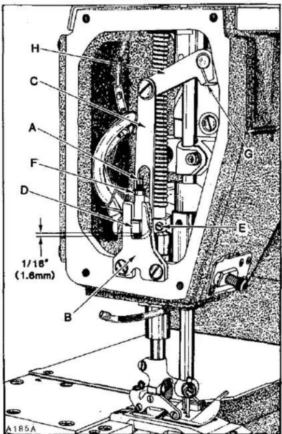
With needle bar at bottom of stroke and presser foot resting squarely on throat plate, there should be a minimum clearance of 1/64 inch (.4mm) between the bottom of screw (A, Fig. 20) and bottom of slot in presser bar guide plate (B). At this time, there should be at LEAST 1/32 inch (.8mm) clearance between bottom of presser bar guide and top of lower presser bar bushing. There should also be 1/16 inch (1.6mm) clearance between bottom of slot in lifter lever link (C) and bottom of presser bar guide (D) when foot lifter lever is released. If adjustment is required, proceed as follows:
Back off presser bar spring regulator to release tension on spring. Loosen two screws (E) in presser bar guide (D). Loosen nut (F) and turn screw (A) down against guide plate (B) to obtain at least 5/64 inch (2.0mm) clearance between bottom of presser bar guide (D) and guide plate (B). Align presser foot with needles and press down FIRMLY while tightening two screws (E) in presser bar guide (D).
NOTE: This setting was necessary to prevent damage to the scraper edge of presser bar bushing, should presser foot be removed from machine.
Turn presser bar spring regulator down. Back off screw (A) to obtain 1/64 inch (.4mm) dimension between bottom of screw and bottom of slot in presser bar guide plate (B), lock nut (F).
Loosen screw (G) in lifter arm (H) and rotate arm slightly as required to obtain the 1/16 inch (1.6mm) dimension between link (C) and guide (D), retighten screw (G) ensuring no left to right shake in lifter arm (H).
Adjust presser bar spring regulator so it exerts only enough pressure on presser foot to feed the work uniformly. Turning it clockwise increases the pressure, counterclockwise acts the reverse.
LOOPER THREAD TAKE-UP AND CAST-OFF PLATE
Looper thread take-up (A, Fig. 21) must be centered front to back in cast-off plate (B). It should also be positioned so as the needle bar is descending, the looper threads are "cast-off" the highest lobe of looper thread take-up when the point of the left needle is even with the bottom of its looper blade.
text_image
H C A F D 1/18" (1.6mm) B G E A185AFig.20
text_image
A197A B C D E F G H JFig.21
LOOPER THREAD TAKE-UP AND CAST-OFF PLATE (Continued)
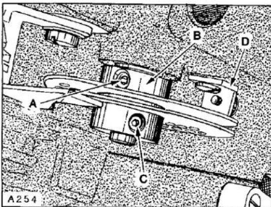
If adjustment is required, lift cast-off plate up. Loosen screw (A, Fig. 22) in positioning collar (B) and two screws (C) in looper thread take-up. Advance or retard take-up as required. Tighten two screws (C) securely in take-up making sure it is centered in cast-off plate. Positioning collar (B), which has a slot in its face, must be aligned with two screws which secure the discs of take-up together while THRUSTING positioning collar forward against take-up. Remove the play between screw heads in take-up and slot in positioning collar by applying pressure on the collar CLOCKWISE while tightening screw (A) securely. Cast-off plate (B, Fig. 21) should be positioned horizontally. Which can be adjusted by repositioning latch (C). Set adjustable eyelets (D) in the center of their mounting screws. More or less, looper thread can be supplied in the stitch by moving adjustable eyelets to the right or left respectively.
text_image
A B D A C A254Fig.22
If retaining finger is rubbing take-up, loosen screw (E), center the finger (F) and retighten screw. If retaining finger is on an angle, loosen screw (G), turn retaining finger support (H) slightly as required and retighten screw. The height of retaining finger can be adjusted by loosening screw (J), set to required height and tighten screw securely.
text_image
A D(3) B(6) C A189Fig.23
THREAD TENSION RELEASE
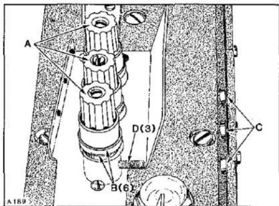
Needle thread tension assemblies (A, Fig. 23) are set correctly when the tension discs (B) start to release as the presser foot is raised to within 1/8 inch (3.2mm) of the end of its travel and completely released when presser foot has reached its highest position.
Adjustment can be made by removing plastic plugs (C), and loosening screws (D) and lower tension assemblies (A) to advance the release action or raise tension assemblies to retard the release action. Hold tension assemblies in position while retightening screws (D). Reassemble plastic plugs securely.
text_image
A165A B AFig.24
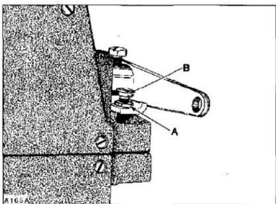
Loosen lock nut (A, Fig. 24) and adjust screw (B) in presser foot lifter lever, allowing presser foot to be raised to its highest position without interfering with needle head. Lock nut (A) securely.
THREAD CONTROL SETTINGS
Needle bar eyelet (A, Fig. 25) should be set with its eyelets 1/16 inch (1.6mm) below strike-off (B) on needle thread take-up cam wire (C), as shown in Figure 25, with needle bar at BOTTOM of stroke.
Adjustments can be made by bringing needle bar up, loosen screw (D) slightly, bring needle bar down to BOT-TOM of stroke, reposition eyelet (A) as required and
THREAD CONTROL SETTINGS (Continued)
bring needle bar back up. Torque screw (D) to 10 in-lbs (11.5 cm/kg).
Needle thread take-up cam wire (C) should be set to barely contact needle threads with needle bar at top of stroke. Adjustment can be made by loosening cam mounting screw (E), reposition cam forward or rearward as required and retighten screw. Auxiliary strike-off (F) should be set so needle threads contact strike-off when needle bar is at BOTTOM of stroke with Thread Control Assembly

text_image
A190A D A C 1/16" (1.6mm) E F BFig.25

text_image
A255 B C 1 2 3 T AFig.26
text_image
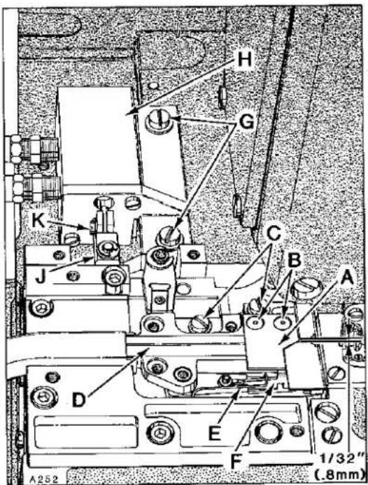
H G K J C B A D E F 1/32" (.8mm) A252Fig.27
adjustable eyelet (C, Fig. 26) set at "T". Loosen secrew (A) and position strike-off (B) as specified and retighten screw. Thread tension on needle thread should be just enough to pull up uniform stitches. Thread tension applied on looper thread should be just enough to steady thread.
POWER "AIR-KLIPP" CHAIN CUTTER ADJUSTMENTS
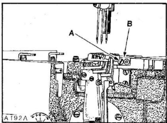
Upper knife (A, Fig. 27) can be replaced by removing two screws (B). To replace lower knife, the upper knife must be removed and rear suction tube cover. Loosen two screws (C) and slide housing (D) towards the rear. Remove throat plate support with throat plate attached. Remove screw (A, Fig. 28) and lift up thread inlet (B). Unhook knife spring (E, Fig. 27) and remove lower knife (F). Reassemble knives in reverse manner. Reassemble thread inlet (B, Fig. 28) and slide housing (D, Fig. 27) forward against rear of throat plate; tighten two screws (C).
text_image
A B A192AFig.28
text_image
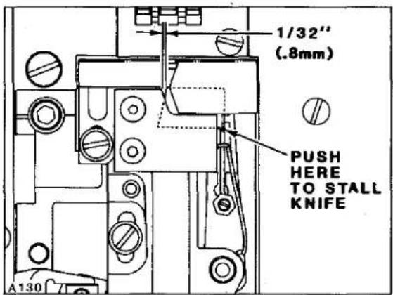
1/32" (.8mm) PUSH HERE TO STALL KNIFE A130KNIFE CROSS OVER

text_image
SHEAR ANGLE A131ASHEAR ANGLE

text_image
SHEAR ANGLE A A251Fig.29
SETTING KNIFE CROSS OVER
Adjustment may be necessary after replacing or repairing knives. With sewing motor switch in "OFF" position and air lines connected to air motor, depress treadle until air motor begins to operate, in and out.
IMPORTANT: Be sure that lower knife does NOT strike against knife housing or feed chamber cover. Adjustment should be accomplished by loosening two screws (G, Fig. 27) and reposition air motor (H) left or right slightly, but under extreme circumstances it may become necessary to shorten the stroke of lower knife travel by repositioning coupling (J).
Carefully press against lower knife (F, Fig. 27) until air motor stalls. With treadle still depressed, check the knife cross over. Cross over of lower knife to upper knife is positioned correctly when the lower knife is 1/32 inch (.8mm) from the front of upper knife as shown in Figure 27. If adjustment is required, loosen screw (K) and reposition coupling (J) as required to obtain specified dimension.
SHEAR ANGLE
Adjustment of shear angle can be made by loosening nut (A, Fig. 29) and turning screw (B) clockwise (a small amount at a time) while manually operating knife lever (C), continuously checking with a piece of thread to see if knives are cutting. As soon as the knives fail to cut thread and the shear angle is zero, turn screw (B) counterclockwise approximately 1/4 turn and lock with nut (A). Check cutting action of knives when air motor is operating.
CAUTION! Turning screw (B) clockwise to an EXTREME may cause damage to "AIR-KLIPP" Chain Cutter assembly.
SETTING PRESSURE VALVES
Regulate valve on pneumatic control device for air motor of the "AIR-KLIPP" chain cutter to approximately 20-22 p.s.i. (1.5 bar) when air motor is operating. Regulate valve on pneumatic control device for the suction air to obtain maximum suction, yet so that the FABRIC TO BE SEWN will not be cut by the "AIR-KLIPP" chain cutter knives.
PULLER TIMING
The Close-Coupled Roller Puller must be timed so the intermittent feeding action stops BEFORE the needles are entering the work. NOTE: This will depend on the thickness of material and stitch length being sewn. If adjustment is required, remove top cover which is secured with four screws. Loosen four set screws (A, Fig. 30) in sprocket (B). Advance or retard sprocket on shaft as required. When proper timing is obtained, position sprocket on its shaft (left or right) so drive belt is centered in the puller drive assembly. Torque four screws (A) to 35 in-lbs. (40 cm/kg). There should be approximately 1/8

text_image
A B A258Fig.30

text_image
A257 D A B CFig.31
inch (3.2mm) deflection in puller drive belt (A, Fig. 31) when pressing firmly between sprocket (B) and puller drive assembly. Adjustment can be made by loosening one screw (C) securing eccentric (D) and rotate eccentric counterclockwise as viewed in (Figure 31), to tighten belt, clockwise acts the reverse. Be sure to maintain .006-.010 inch (.150-.254mm) between eccentric and drive housing. Tighten screw (C) securely. When assembling top cover, care must be taken to center oil flow indicator in center of oil filler cap.
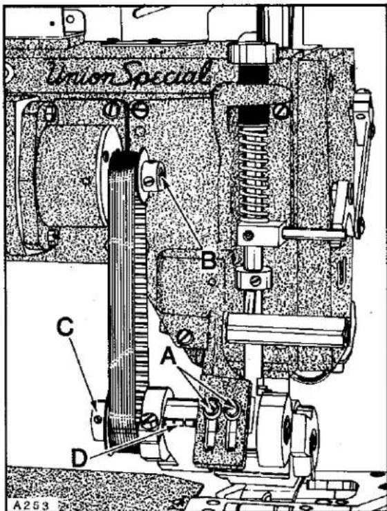
The feeding motion of the puller is achieved by two sprockets. By using various combinations of nine different sprockets, (59) different puller stitch lengths can be obtained. Refer tp sprocket charts on Page 23 that lists the various sprocket combinations. NOTE: Actual stitch length may vary slightly due to material being sewn. When ordering sprockets use the appropriate dash number. Example: C50042-Z-.
To change sprockets loosen two screws (A, Fig. 32) and position screw to top of tension bracket to release tension on stitch length drive belt. NOTE: Belt guard has been removed for clarity. With drive belt in relaxed position, sprocket (B and C) can be removed. When installing sprockets (B and C) make sure that hub of sprocket is flush with end of shaft and 1st screw in operating direction is on the flat of shaft. Reassemble drive belt, tighten 2nd screw in sprockets (B and C) securely. Rotate handwheel in operating direction to make sure belt does not bind within
text_image
Union Special A253Fig.32
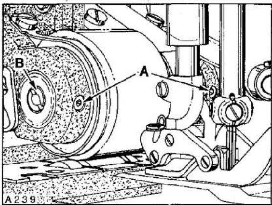
text_image
A B A239Fig.33
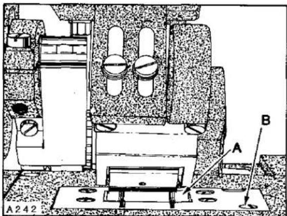
text_image
A242 A BFig.34
PULLER LIFT ADJUSTMENT
With puller in the operating position and presser foot resting on throat plate there should be 1/32 inch (.8mm) between puller lifter link (A, Fig. 35) and puller lifting pin (B). If adjustment is required loosen screw (C) in upper presser foot lifting shaft connection and raise or lower link (A) as required. Tighten connection screw (C) securely..
NOTE: When presser foot starts to lift, puller must lift at the same time.
For sewing operations not requiring puller action the machine can be run with puller raised off the material by turning the manual lock-up pin (D) up to position under stop collar (E). If the puller has insufficient clearance to clear material, stop collar (E) can be raised or lowered on tension shaft (F) to suit. Adjust puller tension regulator (G) so it exerts only enough pressure on puller to feed work. Turning regulator clockwise to increase the pressure, counterclockwise acts the reverse. If material does not pull straight through behind presser foot turn stitch regulator knob until material is straight.
PULLER STITCH LENGTH (Continued)
belt guard. It may be necessary to reposition sprockets (B and C) slightly (left and right). Pull down firmly on puller assembly, making sure puller roller is setting evenly on lower roller and tighten two screws (A) securely. The roller puller belt which is located under hinged belt guard (D) should have 1/8 inch (3.2mm) deflection when pressing firmly between drive shaft sprocket and drive sprocket. If adjustment is required loosen two allen screws (A, Fig. 33) and turn eccentric shaft (B) slightly to apply tension on belt. Turning shaft clockwise tightens belt, counterclockwise acts the reverse. CAUTION: Care must be taken not to disturb eccentric shaft (left or right). Tighten two screws (A) securely.
IDLER ROLLER
Puller Roller must be set evenly on Idler Roller (A, Fig. 34) to ensure that the material will be pulled straight through the sewing area. Adjustment for feeding can be made by shimming Idler Roller if necessary to achieve even mating. To shim roller remove one screw (B, Fig. 34) securing roller assembly. Remove Idler Roller Assembly and add shims as necessary between plate and bearing blocks to ensure mating between Puller Roller and Idler Roller.

text_image
G B 1/32 (8mm) A C E D F U A30Fig.35
PULLER SPROCKETS COMBINATIONS
This chart shows the stitch length produced by available sprocket combinations. Sprockets furnished in the machines produces approximately 9.2 S.P.I. If a different length is required, refer to the chart for appropriate dash number when ordering sprockets-C50042-Z-( ).
Roller Puller Sprocket Variations
| DRIVEN SPROCKET PART NUMBER | NUMBER OF STITCHES PER INCH | ||||||||
| 14.69 SPI(1.73mm) | 13.37 SPI(1.90mm) | 12.25 SPI(2.07mm) | 11.30 SPI(2.25mm) | 10.50 SPI(2.42mm) | 9.80 SPI(2.59mm) | 9.18 SPI(2.77mm) | 8.65 SPI(2.94mm) | ||
| 13.87 SPI(1.83mm) | 12.62 SPI(2.01mm) | 11.56 SPI(2.20mm) | 10.67 SPI(2.38mm) | 9.91 SPI(2.56mm) | 9.25 SPI(2.75mm) | 8.67 SPI(2.93mm) | 8.16 SPI(3.11mm) | 7.71 SPI(3.30mm) | |
| 13.06 SPI(1.94mm) | 11.88 SPI(2.13mm) | 10.89 SPI(2.53mm) | 10.05 SPI(2.53mm) | 9.34 SPI(2.72mm) | 8.71 SPI(2.92mm) | 8.16 SPI(3.11mm) | 7.69 SPI(3.30mm) | 7.26 SPI(3.50mm) | |
| 11.14 SPI(2.28mm) | 10.21 SPI(2.49mm) | 9.42 SPI(2.70mm) | 8.75 SPI(2.90mm) | 8.16 SPI(3.11mm) | 7.65 SPI(3.32mm) | 7.21 SPI(3.52mm) | 6.80 SPI(3.73mm) | ||
| 9.52 SPI(2.67mm) | 8.76 SPI(2.89mm) | 8.16 SPI(3.11mm) | 7.62 SPI(3.33mm) | 7.14 SPI(3.56mm) | 6.72 SPI(3.78mm) | 6.35 SPI(4.00mm) | |||
| 8.16 SPI(3.11mm) | 7.59 SPI(3.35 mm) | 7.08 SPI(3.59mm) | 6.63 SPI(3.83mm) | 6.25 SPI(4.07mm) | 5.90 SPI(4.31mm) | ||||
| 7.00 SPI(3.63mm) | 6.53 SPI(3.89mm) | 6.12 SPI(4.15mm) | 5.76 SPI(4.41mm) | 5.44 SPI(4.67mm) | |||||
| 5.98 SPI(4.24mm) | 5.61 SPI(4.53mm) | 5.28 SPI(4.81mm) | 4.99 SPI(5.09mm) | ||||||
| 5.10 SPI(4.98mm) | 4.81 SPI(5.28mm) | 4.54 SPI(5.60mm) | |||||||
| C50042-Z-10,A304 DRIVE SPROCKET PART NUMBER | |||||||||
GENERAL PREVENTIVE MAINTENANCE SCHEDULE
| LF600 TASK | DAILY | AFTER FIRST MONTH | EVERY MONTH | EVERY -3-MONTHS | EVERY -6-MONTHS | YEARLY |
| Check oil level (sight gauge)oil level between red lines. | LF600 | |||||
| Check pump operation(oil flow indicator-top of arm) | LF600 | |||||
| Clean lint and dirt from machine | LF600 | |||||
| Check that all guards and shields are in place and being used | LF600 | |||||
| Change oil-filter(housed-on machine bottom cover) | LF600 | LF600 | ||||
| Change oil (oil which conforms to U.S.C. spec 175 must be used) | LF600 | LF600 | ||||
| Clean lint and dirt from suction screen(inside bottom cover) | LF600 | |||||
| Check tension on internal timing belts | LF600 | LF600 | ||||
| Inspect clutch/position motor,V-belt, tension and wear | LF600 | |||||
| Check clutch motor clutch/brake adjustment | LF600 | |||||
| Clean lint from clutch/positioner motor air passages | LF600 | LF600 | ||||
| Check needles bent, blunt, sharp or worn eye or groove | LF600 |
NOTE: SCHEDULING IS BASED ON NORMAL WORKING CONDITIONS FREQUENCY OF TASKS DEPENDS ON MACHINE DUTY CYCLE TIME AND PERSONNEL RESPONSIBLE TO PERFORM TASK DETERMINED BY PLANT MANAGEMENT
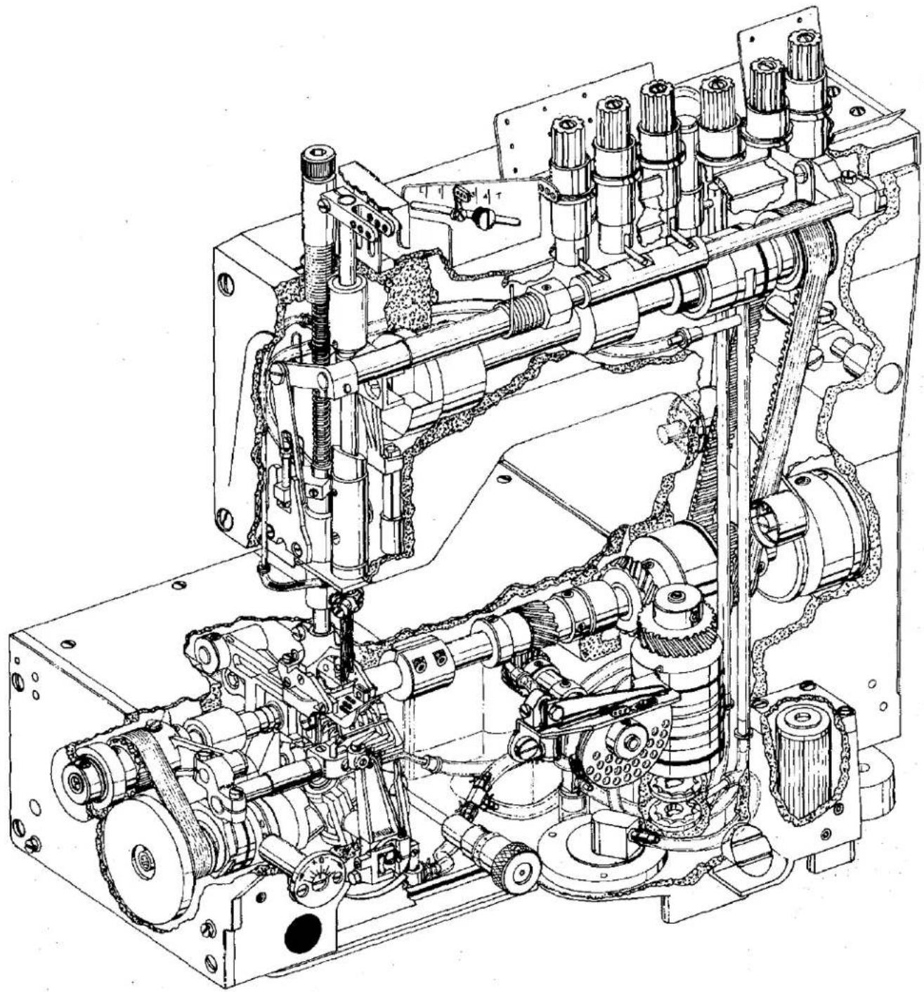
natural_image
Technical line drawing of a mechanical assembly with gears, springs, and housing (no text or labels)P191
EXPLODED VIEWS
AND
DESCRIPTION OF PARTS
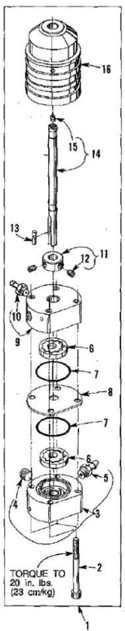
text_image
TORQUE TO 20 in. lbs. (23 cm/kg) 1 2 3 4 5 6 7 8 9 10 11 12 13 14 15 16
P185A

text_image
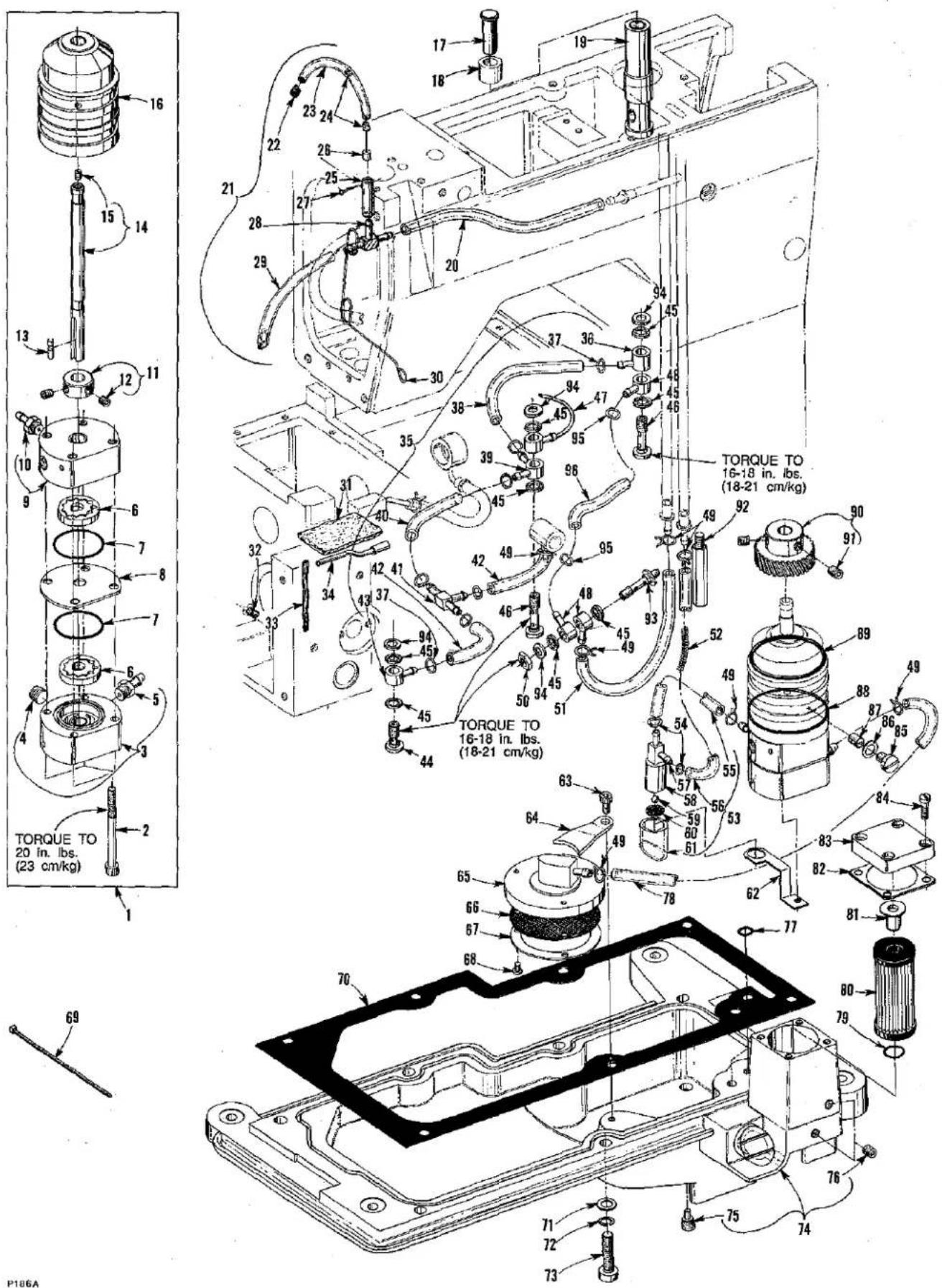
TORQUE TO 16-18 in. lbs. (18-21 cm/kg) TORQUE TO 16-18 in. lbs. (18-21 cm/kg)OIL PUMP, PAN AND LUBRICATION PARTS
| Ref. No. | Part No. | Description | Amt. Req. |
| 1 | 50393 CB | Oil Pump Assembly | 1 |
| 2 | 22653 B-36 | Screw | 4 |
| 3 | 50393 CD | Housing, pump (pressure side) | 1 |
| 4 | 22571 F | Screw, plug | 1 |
| 5 | 50394 X | Connector, tube | 1 |
| 6 | C50093 U | Gerotor, 1/4 inch (6.4mm) thick | 2 |
| 7 | 660-684 | "O" Ring | 2 |
| 8 | 50393 CE | Divider, housing | 1 |
| 9 | 50393 CC | Housing, pump (syphon side) | 1 |
| 10 | 50394 X | Connector, tube | 1 |
| 11 | 35036 X | Collar, (positioning and thrust) | 1 |
| 12 | 22894 C | Screw | 2 |
| 13 | C50093 Z | Pin, drive | 1 |
| 14 | 50393 D | Shaft, drive | 1 |
| 15 | 89 | Screw | 1 |
| 16 | 50393 C | Bushing, oil delivery | 1 |
| 17 | 50393 CP | Cap, oil indicator | 1 |
| 18 | 50393 CR | Sleeve, oil indicator | 1 |
| 19 | 50393 CN | Indicator, oil (priority metering valve) | 1 |
| 20 | 50393 AX | Tube, oil return | 1 |
| 21 | 50393 DC | Head Oil Return Assembly | 1 |
| 22 | 50393 CS | Spring, tube retainer | 1 |
| 23 | 50393 CU | Tube, oil return | 1 |
| 24 | 666-322 | Felt | 2 |
| 25 | 50393 AY | Tube, oil | 1 |
| 26 | 50393 BB | Restrictor | 1 |
| 27 | PI-18 | Pin | 1 |
| 28 | 671 F-41 | Tee, union | 1 |
| 29 | 50393 CY | Tube, oil return | 1 |
| 30 | 50393 V | Retainer, wire (oil tube) | 1 |
| 31 | 660-310 | Felt, oil return | 1 |
| 32 | C50094 AK | Plug, felt, oil return | 1 |
| 33 | WO-3 | Yarn, Columbia, rear needle guard bushing (8 strands) | 1 |
| 34 | 50394 G | Tube, oil (looper rocker) | 1 |
| 35 | 50393 DJ | Oil Tube Assembly | 1 |
| 36 | 50394 K | Connector, oil (single feed) | 1 |
| 37 | RI-37 | Ring, wire | 7 |
| 38 | 35093 BL | Tube, oil | 1 |
| 39 | C50094 B | Connector, oil (double feed) | 1 |
| 40 | C50094 AH | Tube, oil | 1 |
| 41 | 671 F-41 | Tee, union | 1 |
| 42 | C50094 P | Tube, oil | 2 |
| 43 | C50094 C | Connector, oil (single feed) | 1 |
| 44 | 22720 A | Screw, oil connection | 1 |
| 45 | 41350 X | Washer, fiber | 8 |
| 46 | 35094 A | Screw, oil connection | 2 |
| 47 | 50394 L | Tube, oil, complete (take-up gear) | 1 |
| 48 | C50094 C | Connector, oil (single feed) | 3 |
P186A
OIL PUMP, PAN AND LUBRICATION PARTS
| Ref. No. | Part No. | Description | Amt. Req. |
| 1 thru 48 | See Preceding Page | ||
| 49 | 660-885 | Clamp, oil | 7 |
| 50 | 258 | Nut | 1 |
| 51 | C50094 R | Tube, oil | 1 |
| 52 | 56393 N | Spring | 1 |
| 53 | 50393 AW | Oil Syphon Assembly | 1 |
| 54 | RI-37 | Ring, wire | 2 |
| 55 | C50093 CJ | Tube, oil return | 1 |
| 56 | 52393 Q | Tube, oil | 1 |
| 57 | 671 F-41 | Fitting, oil syphon | 1 |
| 58 | 50393 AV | Manifold, oil syphon | 1 |
| 59 | 28619 | Ball, steel | 1 |
| 60 | 50393 AU | Screen, oil filter | 1 |
| 61 | 50393 BU | Extension, manifold | 1 |
| 62 | 50393 BA | Bracket, manifold | 1 |
| 63 | 22652 A-6 | Screw | 1 |
| 64 | 50393 AR | Clamp, oil screen housing | 1 |
| 65 | 35093 F | Housing, screen | 1 |
| 66 | 35093 H | Screen | 1 |
| 67 | 35093 J | Plate, retaining | 1 |
| 68 | 97 | Screw | 1 |
| 69 | 670 E-2 | Tie, cable (to secure Ref. No. 55 to Ref. No. 93) | 1 |
| 70 | 50382 BH | Gasket, oil pan | 1 |
| 71 | 6042 A | Washer | 7 |
| 72 | 6524-16 | Washer, lock | 7 |
| 73 | 820 | Screw | 7 |
| 74 | 50393 N | Pan, oil | 1 |
| 75 | 22571 E | Screw, oil drain plug (magnetic) | 1 |
| 76 | 22571 J | Screw, plug | 2 |
| 77 | 999-211 E | "O" Ring | 2 |
| 78 | C50094 Y | Tube, oil | 1 |
| 79 | 660-206 | "O" Ring | 1 |
| 80 | C50093 CA | Filter, oil | 1 |
| 81 | C50093 CB | By-Pass, oil filter | 1 |
| 82 | 50393 DM | Gasket | 1 |
| 83 | C50093 F | Cover, oil filter | 1 |
| 84 | 22541 | Screw | 4 |
| 85 | 22586 U | Screw, plug | 1 |
| 86 | 41350 X | Washer, fiber | 1 |
| 87 | 74 E | Screw | 1 |
| 88 | 660-455 | "O" Ring | 1 |
| 89 | 661-51 | "O" Ring | 1 |
| 90 | 35039 A | Gear, driven (oil pump) | 1 |
| 91 | 22894 J | Screw | 2 |
| 92 | 22841 M | Stand, oil plug | 1 |
| 93 | 50393 BK | Fitting, oil | 1 |
| 94 | 6042 A | Washer | 4 |
| 95 | RI-37 | Ring, wire | 2 |
| 96 | 50394 B | Tube, oil | 2 |
text_image
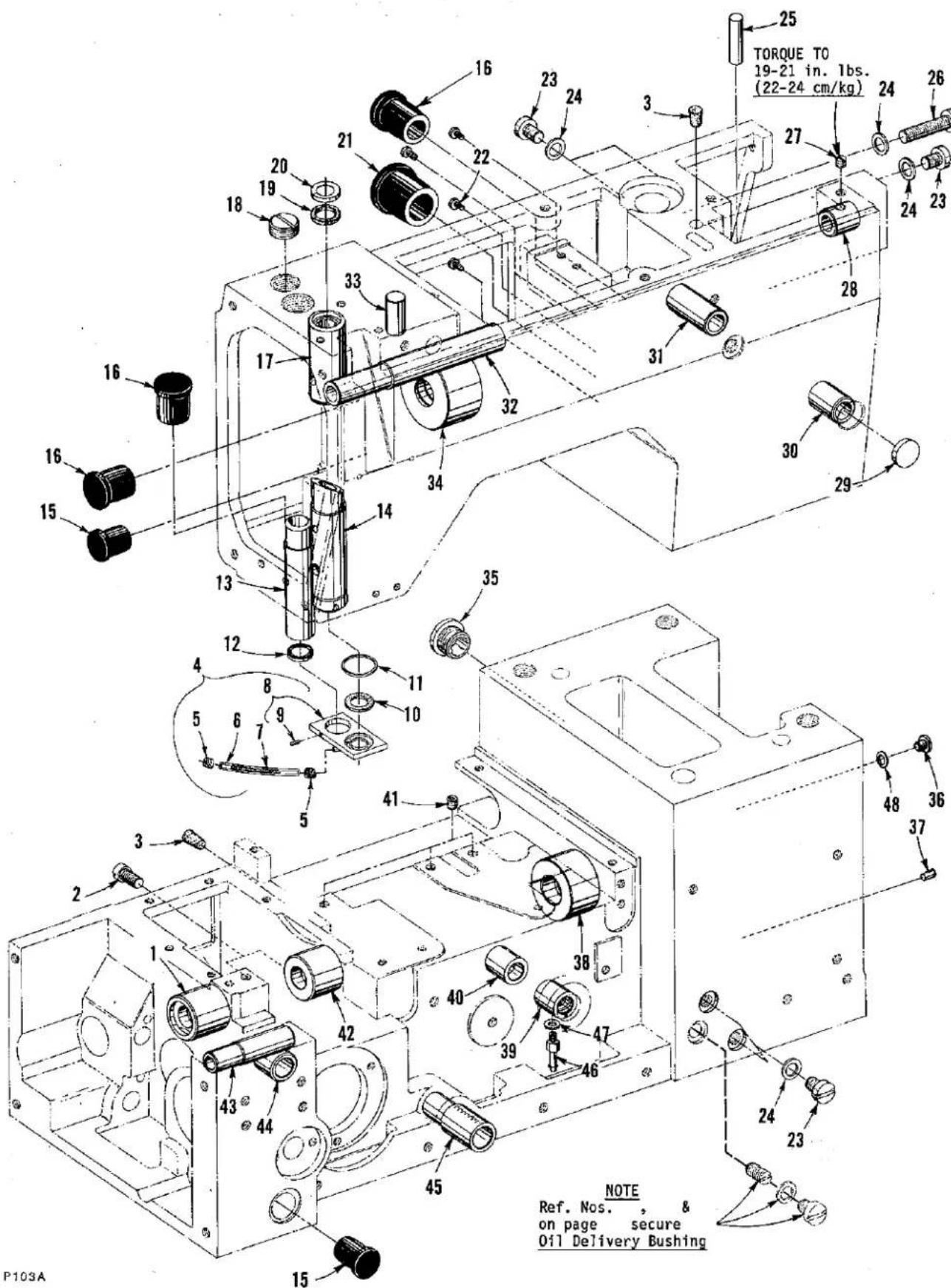
P103A NOTE Ref. Nos. , & on page secure Oil Delivery BushingMAINFRAME BUSHINGS AND PLUGS
| Ref. No. | Part No. | Description | Amt. Req. |
| 1 | 50344 K | Bushing, lower main shaft (left) | 1 |
| 2 | 136 A | Screw, plug | 2 |
| 3 | CO67 B | Plug, cork | 2 |
| 4 | 50393 DD | Needle Bar Oil Collector Plate Assembly | 1 |
| 5 | 50393 CS | Spring, tube retainer | 2 |
| 6 | 50393 CV | Tube, oil return | 1 |
| 7 | 50393 CZ | Spring | 1 |
| 8 | 50393 CX | Plate, oil collector | 1 |
| 9 | 22733 | Screw | 1 |
| 10 | 666-321 | Felt, oil return | 1 |
| 11 | 661-1 | "O" Ring, for lower needle bar bushing | 1 |
| 12 | 660-739 | Seal, oil (presser bar bushing) | 1 |
| 13 | C50057 D | Bushing, presser bar | 1 |
| 14 | 50354 E | Bushing, needle bar (lower) | 1 |
| 15 | C50093 CT | Plug, oil | 2 |
| 16 | C50093 AY | Plug, oil | 3 |
| 17 | 50354 D | Bushing, needle bar (upper) | 1 |
| 18 | 22539 G | Screw, plug | 1 |
| 19 | 666-311 | Screen, needle bar bushing | 1 |
| 20 | C50054 D | Shield, needle bar bushing | 1 |
| 21 | C50093 AX | Plug, oil | 1 |
| 22 | 604 | Screw, plug | 4 |
| 23 | 22586 U | Screw, plug | 6 |
| 24 | 41350 X | Washer, fiber | 1 |
| 25 | 50394 S | Plug, steel | 1 |
| 26 | 820 | Screw, plug | 1 |
| 27 | 22764 C | Screw, spot | 1 |
| 28 | 50390 C | Bushing, presser foot lifter lever (right) | 1 |
| 29 | 51-627 BLK. | Plug | 1 |
| 30 | 50390 A | Bushing, presser foot lifter lever (front) | 1 |
| 31 | 50390 | Bushing, presser foot lifter lever (rear) | 1 |
| 32 | 50390 D | Bushing, presser foot lifter lever (left) | 1 |
| 33 | 51-794 BLK. | Plug, aluminum | 1 |
| 34 | 50355 L | Bushing, upper mainshaft | 1 |
| 35 | 98540 | Plug, threaded | 1 |
| 36 | 22569 F | Screw | 1 |
| 37 | C50093 BG | Plug, aluminum | 1 |
| 38 | 50344 L | Bushing, lower mainshaft (right) | 1 |
| 39 | 50344 V | Bushing, take-up shaft (front) | 1 |
| 40 | 50344 X | Bushing, take-up shaft (rear) | 1 |
| 41 | 22894 C | Screw, plug | 3 |
| 42 | 50344 B | Bushing, lower mainshaft (intermediate) | 1 |
| 43 | 50368 B | Bushing, needle guard shaft | 1 |
| 44 | 50344 E | Bushing, looper rocker (rear) | 1 |
| 45 | 35036 AB | Bushing, stitch control shaft | 1 |
| 46 | 671 F-4 | Fitting | 1 |
| 47 | RM2964-B | Gasket | 1 |
| 48 | 50339 B | Washer, fiber | 1 |

text_image
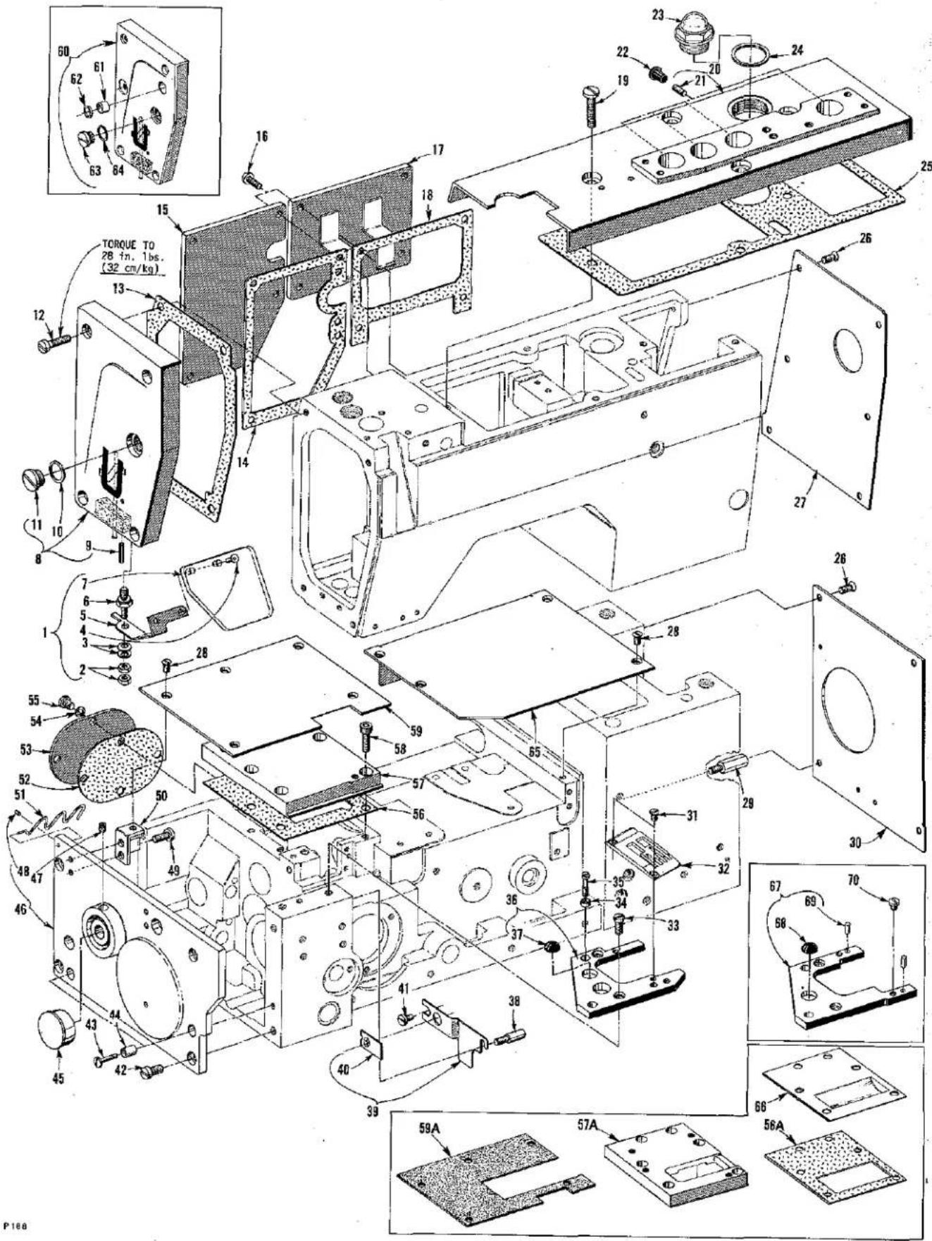
Technical diagram of an internal combustion engine assembly with numbered components and labeled torque values in Chinese.SAFETY SHIELD, COVERS AND CLOTH PLATES
| Ref. No. | Part No. | Description | Amt. Req. |
| 1 | C50095 G | Safety Shield Assembly | 1 |
| 2 | 12934 A | Nut | 2 |
| 3 | 97127 | Washer, spring | 2 |
| 4 | RM2879-2 | Rivet | 2 |
| 5 | C50095 E | Bracket, mounting | 1 |
| 6 | C50095 D | Stud | 1 |
| 7 | C50095 F | Shield, safety | 1 |
| 8 | 50382 BN | Cover, head, all styles except LF612K101MBE-16,LF613K101HR-8 and 101HR-9 | 1 |
| 9 | 660-219 A | Pin, roll (stop) | 1 |
| 10 | C50082 AA | Gasket | 1 |
| 11 | 22883 B | Screw, plug | 1 |
| 12 | 22541 C | Screw | 4 |
| 13 | C50082 AW | Gasket | 1 |
| 14 | C50082 K | Gasket | 1 |
| 15 | C50082 V | Cover, head (left rear) for all styles except LF612K101MBE-16,LF613K101HR-8, and 101HR-9 | 1 |
| 16 | 22569 M | Screw | 9 |
| 17 | C50082 M | Cover, head (right rear) for all styles except LF612K101MBE-16,LF613K101HR-8, and 101HR-9 | 1 |
| 18 | C50082 N | Gasket | 1 |
| 19 | 22861 C | Screw | 4 |
| 20 | 50382 K | Cover, top | 1 |
| 21 | 22894 J | Screw | 4 |
| 22 | 50394 J | Plug | 4 |
| 23 | C50093 AU | Cap, oil filter | 1 |
| 24 | C50082 X | Gasket | 1 |
| 25 | 50382 F | Gasket | 1 |
| 26 | 22526 H | Screw | 10 |
| 27 | 50382 J | Cover | 1 |
| 28 | 22525 E | Screw | 9 |
| 29 | 22841 N | Screw, adapter | 1 |
| 30 | 50382 H | Cover | 1 |
| 31 | 87 | Screw, for style LF612K101MBE-16 | 2 |
| 32 | ---- | Throat Plate, see "Sewing Combinations" | 1 |
| 33 | 22839 | Screw | 2 |
| 34 | 35036 AE | Ferrule, locating | 2 |
| 35 | 22587 N | Screw | 2 |
| 36 | 50380 | Support, throat plate, for Style LF612K101MBE-16 | 1 |
| 37 | 660-939 | Bumper, rubber | 1 |
| 38 | 22799 AH | Stud, latch spring | 1 |
| 39 | 50393 U | Shield, lint | 1 |
| 40 | 50393 AS | Gromment, rubber | 1 |
| 41 | 22569 D | Screw | 1 |
| 42 | 22517 | Screw | 4 |
| 43 | 22541 A | Screw | 2 |
| 44 | 50336 L | Ferrule, locating (end cover) | 2 |
| 45 | 999-216 C | Plug, plastic | 1 |
46 thru 70
See Following Page
text_image
Technical schematic diagram of a mechanical assembly with numbered components and labeled parts in ChineseSAFETY SHIELD, COVERS AND CLOTH PLATES
| Ref. No. | Part No. | Description | Amt. Req. |
| 1 Thru 45 | See Preceding Page | ||
| 46 | 50382 A | Cover, end | 1 |
| 47 | 22894 C | Screw (bearing) | 2 |
| 48 | 22571 H | Screw | 1 |
| 49 | 93 | Screw, all styles except LF612K112HJ-16, 112HJ-18, LF613K112HR-8 and 112HR-9 | 4 |
| - | 93 | Screw, for styles LF612K112HJ-16, 112HJ-18, LF613K112HR-8 and 112HR-9 | 2 |
| 50 | 50301 B | Support, cloth plate, all styles except LF612K112HJ-16 112HJ-18, LF613K112HR-8 and 112HR-9 | 2 |
| - | 50301 B | Support, clothplate, for styles LF612K112HJ-16, 112HJ-18, LF613K112HR-8 and 112HR-9 | 1 |
| 51 | 50394 Y | Wire | 1 |
| 52 | 35082 F | Gasket | 1 |
| 53 | 35082 E | Cover, feed chamber (rear) | 1 |
| 54 | 50339 B | Washer, fiber | 4 |
| 55 | 22569 D | Screw | 4 |
| 56 | 50382 BT | Gasket, for all styles except LF612K101MBE-16, LF613K101HR-8 and 101HR-9 | 1 |
| 56A | 50382 U | Gasket for styles LF612K101MBE-16, LF613K101HR-8, and 101HR-9 | 1 |
| 57 | 50382 EA | Cover, feed chamber (top) for styles LF612K100HB-1, HC-1, HJ-16, HJ-18, HR-18, MP-12, MP-16, MX-24, LF613K100HJ-8, HJ-9, HR-8, and HR-9 | 1 |
| 57A | 50382 V | Cover,feed chamber (top) for styles LF612K101MBE-16, LF613K101HR-8, and 101HR-9 | 1 |
| 58 | 22653 B-8 | Screw | 6 |
| 59 | 50301 R | Plate, cloth (left) for styles LF612K100HB-1, HC-1, HJ-16, HJ-18, HR-18, MP-12, MP-16, MX-24, LF613K100HJ-8, HJ-9, HR-8, and HR-9 | 1 |
| 59A | 50301 AD | Plate, cloth (left) for style LF612K101MBE-16 | 1 |
| - | 50301 AE | Plate, cloth (left) for styles LF613K101HR-8 and 101HR-9 | 1 |
| 60 | 50382 BM | Cover, head, for styles LF612K101MBE-16, LF613K101HR-8 and 101HR-9 | 1 |
| 61 | 660-896 | Bushing | 1 |
| 62 | 660-739 | Seal, oil | 1 |
| 63 | 22883 B | Screw, plug | 1 |
| 64 | C50082 AA | Gasket | 1 |
| 65 | 50301 | Plate, cloth (right) | 1 |
| 66 | 37-70 BLK. | Trough, blank, for styles LF612K101MBE-16, LF613K101HR-8, and 101HR-9 | 1 |
| 67 | 50380 D | Support, Throatplate, for all styles except LF612K101MBE-16 | 1 |
| 68 | 660-939 | Bumper, rubber | 1 |
| 69 | 51280 K | Pin, dowel | 2 |
| 70 | 22570 | Screw, for all styles except LF612K101MBE-16 | 2 |

text_image
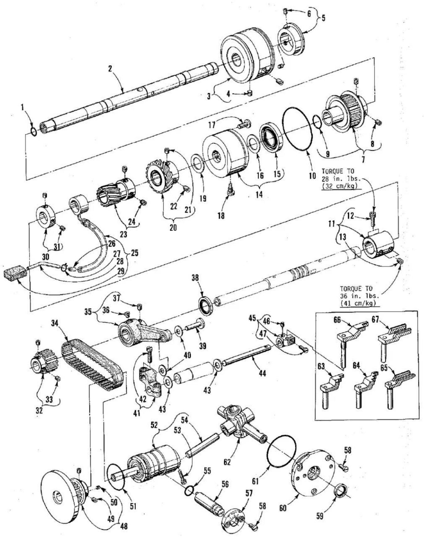
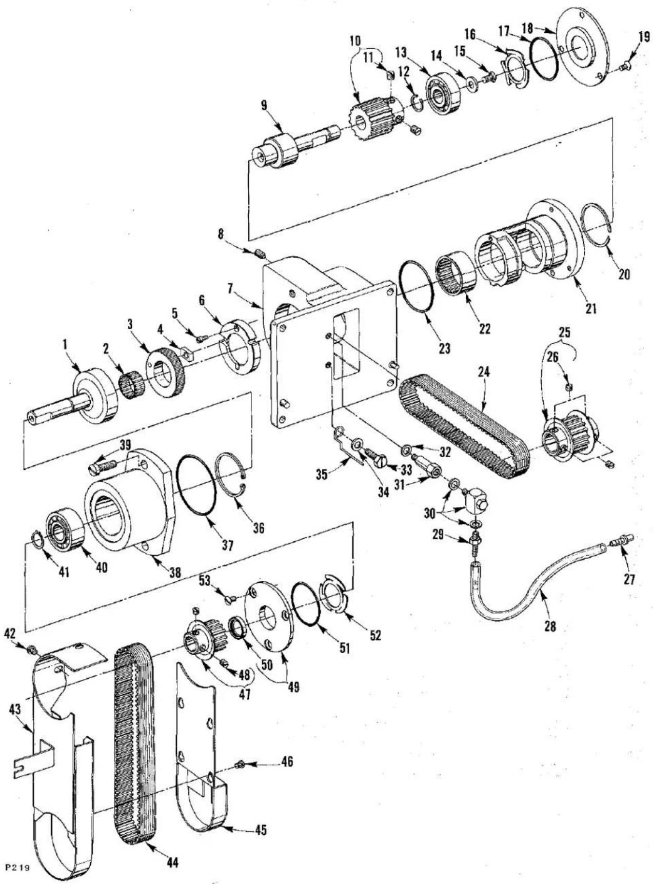
TORQUE TO 16-18 in. 1bs. (18-21 cm/kg) TORQUE TO 22-25 in. 1bs. (25.3-28.8 cm/kg) TORQUE TO 55 in. 1bs. (63 cm/kg) TORQUE TO 28 in. 1bs. (32 cm/kg) TORQUE TO 55 in. 1bs. (63 cm/kg)NEEDLE DRIVE (SCOTCH YOKE) AND ASSOCIATED PARTS
| Ref. No. | Part No. | Description | Amt. Req. |
| 1 | 50355 AE | Stud, support | 1 |
| 2 | 22655 B-7 | Screw | 1 |
| 3 | 50355 H | Yoke Assembly | 1 |
| 4 | 54249 D | Washer | 1 |
| 5 | 22596 H | Screw | 1 |
| 6 | 22720 C | Screw | 1 |
| 7 | C50094 X | Fitting, barbed | 1 |
| 8 | 41350 X | Washer | 1 |
| 9 | C50093 CJ | Tube, air | 1 |
| 10 | CO67 D | Cork | 1 |
| 11 | 50355 P | Scotch Yoke Assembly, all styles except LF612K100MP-12, MP-16, MX-24 and 101MBE-16 | 1 |
| - | 50355 T | Scotch Yoke Assembly, for styles LF612K100MP-12, MP-16, MX-24 and 101MBE-16 | 1 |
| 12 | 88 B | Screw | 1 |
| 13 | J80 K | Screw | 1 |
| 14 | 22591 | Screw | 1 |
| 15 | 35091 A | Flywheel | 1 |
| 16 | 22894 J | Screw | 2 |
| 17 | 660-713 | Ring, retaining | 1 |
| 18 | C50036 P | Bearing and Collar Assembly | 1 |
| 19 | 22894 AD | Screw | 2 |
| 20 | 35093 P | Housing, scotch yoke drive | 1 |
| 21 | 660-708 | "O" Ring | 1 |
| 22 | 660-680 | Seal, lip | 1 |
| 23 | 25 S | Screw | 2 |
| 24 | C50055 H | Screw, Set | 1 |
| 25 | 22706 C | Screw, locking | 1 |
| 26 | 50342 AC | Sprocket, scotch yoke drive | 1 |
| 27 | 22651 CD-4 | Screw | 1 |
| 28 | 50342 AB | Flange, sprocket | 1 |
| 29 | 22562 A | Screw | 1 |
| 30 | C50021 A | Handwheel | 1 |
| 31 | 22894 C | Screw | 2 |
| 32 | 50342 R | Belt | 1 |
| 33 | 50342 V | Screw, shoulder | 2 |
| 34 | 50342 X | Fan, spring | 2 |
| 35 | 35042 C | Roller, idler | 2 |
| 36 | 50342 Y | Spacer | 2 |
| 37 | 258 | Nut | 2 |
| 38 | 50342 U | Bolt | 1 |
| 39 | 652-20 | Washer | 1 |
| 40 | 50342 W | Arm, pivot | 1 |
| 41 | RM2747-3 | Washer, lock (internal tooth) | 1 |
| 42 | 50342 AF | Fan, spring | 1 |
| 43 | 50342 AD | Roller, idler | 1 |
| 44 | 652 B-24 | Washer, lock (external tooth, 1 to 4 at base) | as req. |
text_image
Technical diagram of mechanical assembly with numbered components and torque specifications in ChineseLOWER MAINSHAFT, LOOPER AND REAR NEEDLE GUARD DRIVE
| Ref. No. | Part No. | Description | Amt. Req. |
| 1 | 660-220 | "O" Ring | 1 |
| 2 | 50322 AB | Mainshaft, lower (right) | 1 |
| 3 | 35021 | Pulley | 1 |
| 4 | 22650 CD-6 | Screw, set | 2 |
| 5 | 35021 B | Guard, pulley | 1 |
| 6 | 22894 C | Screw, set | 2 |
| 7 | 50342 H | Sprocket, lower mainshaft (right) | 1 |
| 8 | 22894 X | Screw | 2 |
| 9 | 660-212 | "O" Ring | 1 |
| 10 | 660-935 | "O" Ring | 1 |
| 11 | 50343 | Coupling, lower mainshaft | 1 |
| 12 | 22652 A-8 | Screw | 2 |
| 13 | 22894 AE | Screw, set | 2 |
| 14 | 50393 S | Housing, lower mainshaft | 1 |
| 15 | 660-998 | Seal, oil | 1 |
| 16 | 35055 V | Washer, thrust | 1 |
| 17 | 25 S | Screw, retaining (lower mainshaft housing) | 1 |
| 18 | 62245 C | Stud, locating | 1 |
| 19 | 35055 V | Washer, thrust | 1 |
| 20 | 50339 | Gear, oil pump drive (nylon) | 1 |
| 21 | 22894 AD | Screw, set | 1 |
| 22 | 22894 K | Screw, spot | 1 |
| 23 | 50342 D | Gear, take-up drive | 1 |
| 24 | 22894 C | Screw | 2 |
| 25 | 50393 AN | Oil Syphon Pump Assembly | 1 |
| 26 | 56393 AA | Insert, oil tube | 1 |
| 27 | 660-885 | Clamp, tube | 1 |
| 28 | 50393 AL | Tube, brass | 1 |
| 29 | 666-214 | Felt | 1 |
| 30 | 57847 | Collar | 1 |
| 31 | 95 | Screw | 2 |
| 32 | 50342 B | Sprocket, looper drive | 1 |
| 33 | 22894 AD | Screw | 2 |
| 34 | C50042 AD | Belt, looper drive | 1 |
| 35 | 50368 C | Connecting Rod, needle guard | 1 |
| 36 | 22830 | Screw | 1 |
| 37 | 22894 AD | Screw | 2 |
| 38 | 660-934 | Seal, oil | 1 |
| 39 | 50368 A | Pin, pivot | 1 |
| 40 | 50368 E | Washer, non-metallic | 2 |
| 41 | 50368 | Connection, rear needle guard pivot | 1 |
| 42 | 22729 | Screw | 2 |
| 43 | 6042 A | Washer, thrust | 2 |
| 44 | 50368 F | Shaft, rear needle guard | 1 |
| 45 | C50025 F | Holder, needle guard | 1 |
| 46 | 22764 | Screw, spot | 1 |
| 47 | 22562 A | Screw | 1 |
| 48 | 50342 A | Sprocket, looper driven | 1 |
| 49 | 22894 AD | Screw | 2 |
| 50 | 22894 AF | Screw, set | 2 |
| 51 | 660-979 | "O" Ring | 1 |
| 52 | 29105 AT | Looper Drive Assembly | 1 |
| 53 | 22653 J-8 | Screw | 1 |
| 54 | 667 J-33 | Crankpin | 1 |
| 55 | 660-206 | "O" Ring | 1 |
| 56 | 50314 B | Eccentric, looper avoid adjusting | 1 |
| 57 | 50314 A | Plate, eccentric retaining | 1 |
| 58 | 22569 G | Screw | 5 |
| 59 | C50044 V | Seal, oil | 1 |
| 60 | 50344 C | Housing, looper rocker bearing | 1 |
| 61 | 660-455 | "O" Ring | 1 |
| 62 | 29192 AE | Rocker Assembly, looper | 1 |
| 63 | C50025 L | Guard, needle, for Styles LF612K100HJ-16, HJ-18, 112HJ-16, 112HJ-18, 100HR-18 and 101MBE-16 | 1 |
| 64 | C50025 E | Guard, needle, for Styles LF613K100HJ-8, HJ-9, HR-8, HR-9, 101HR-8, 101HR-9, 112HR-8 and 112HR-9 | 1 |
| 65 | 50325 K | Guard, needle, for Style LF612K100HB-1 | 1 |
| 66 | C50025 N | Guard, needle, for Styles LF612K100MP-12, MP-16, and MX-24 | 1 |
| 67 | 50325 H | Guard, needle, Style LF612K100HC-1 | 1 |
text_image
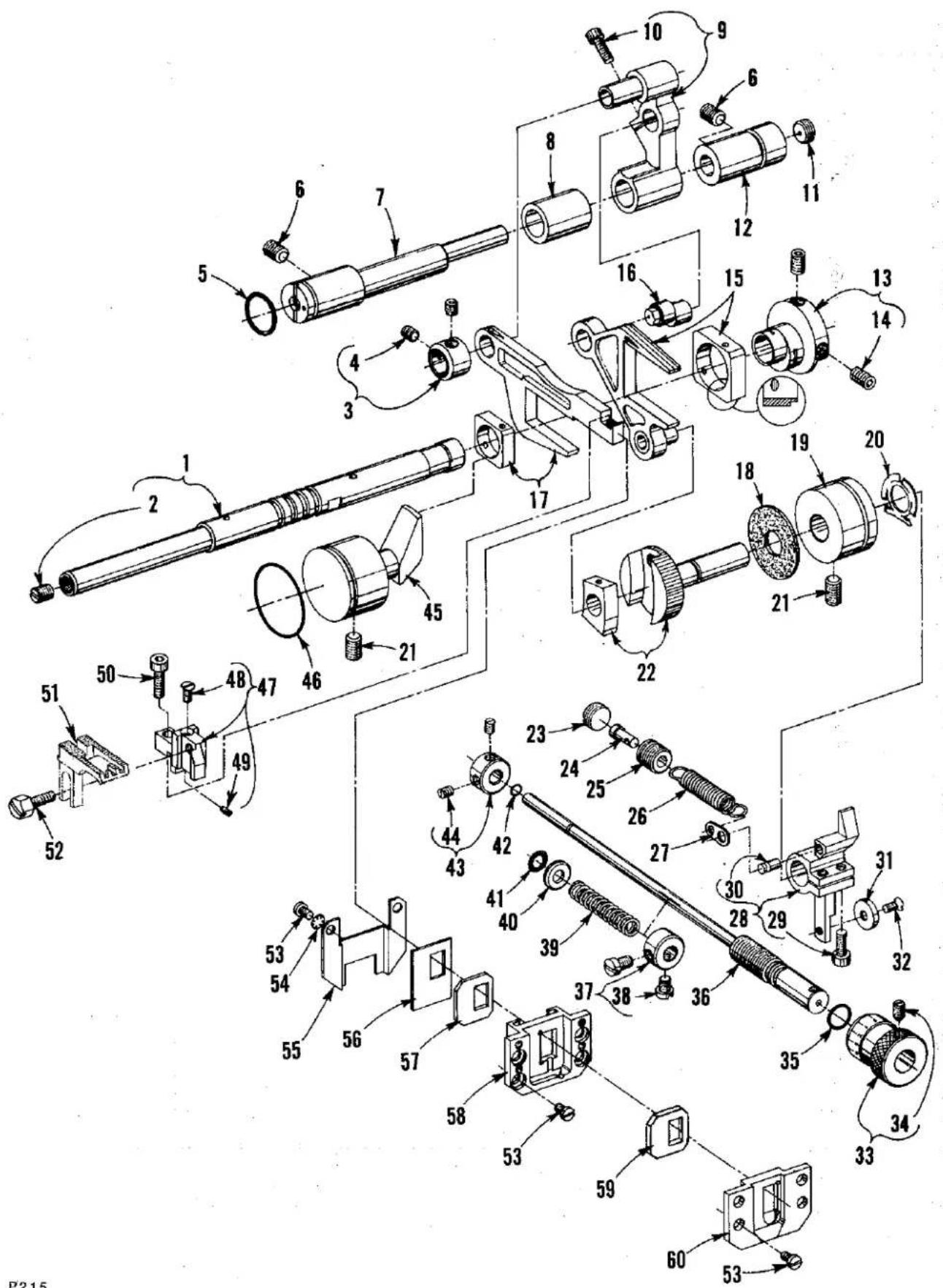
Technical diagram of a mechanical assembly with numbered components for identification and assembly reference.P215
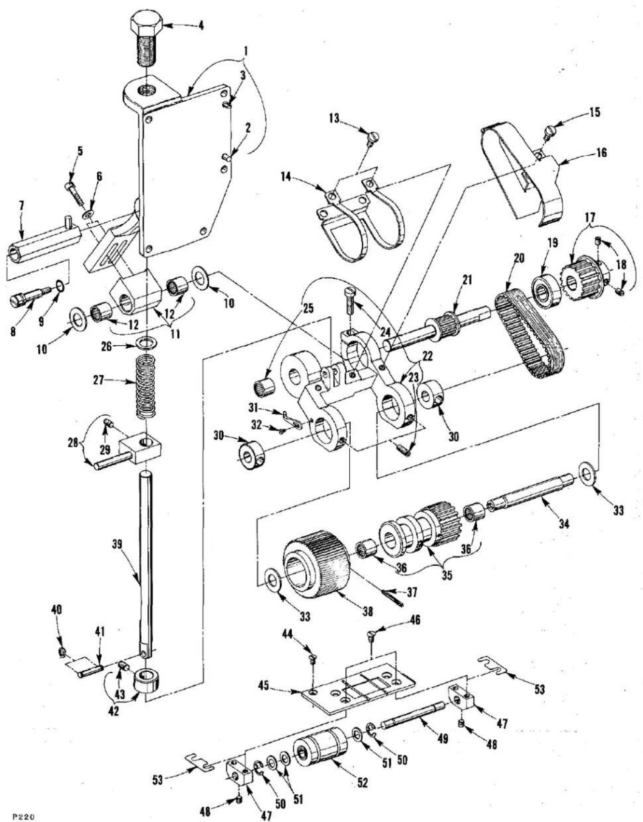
FEED DRIVE AND STITCH REGULATING PARTS
| Ref. No. | Part No. | Description | Amt. Req. |
| 1 | 50322 K | Mainshaft, lower (left) | -1 |
| 2 | 22591 | Screw | -1 |
| 3 | 50335 L | Collar, feed bar thrust | -1 |
| 4 | 22894 C | Screw, set | -2 |
| 5 | 999-211 C | "O" Ring | -1 |
| 6 | 22591 A | Screw, set | -1 |
| 7 | 35034 N | Shaft, rocker | -1 |
| 8 | 50336 C | Spacer, rocker shaft | -1 |
| 9 | 50334 K | Rocker, feed | -1 |
| 10 | 22596 H | Screw | -1 |
| 11 | 22571 D | Screw, adjusting | -1 |
| 12 | 35034 M | Bushing, rocker shaft | -1 |
| 13 | 35040 B-15 | Eccentric, double, for Styles LF612K100MP-12, MP-16, MX-24, and 101MBE-16 | -1 |
| - | 35040 B-22 | Eccentric, double, for Styles LF612K100HB-1, HC-1,HJ-16, HJ-18, HR-18, 112HJ-16 112HJ-18, LF613K100HJ-8, HJ-9, 101HR-8, and 101HR-9 | -1 |
| - | 35040 B-25 | Eccentric, double, for Styles LF613K100HR-8, HR-9, 112HR-8 and 112HR-9 | -1 |
| 14 | 22894 J | Screw, set | -2 |
| 15 | 29126 FB | Fork Assembly, driving | -1 |
| 16 | 35034 X | Stud, eccentric | -1 |
| 17 | 29126 EV | Feed Bar Assembly | -1 |
| 18 | 35036 AZ | Pad, brake | -1 |
| 19 | 35036 F | Bushing, stitch adjusting shaft | -1 |
| 20 | 661-96 | Washer, spring | -1 |
| 21 | 22894 AB | Screw | -2 |
| 22 | 35036 BN | Shaft Assembly, stitch adjusting | -1 |
| 23 | 22539 V | Plug, screw | -1 |
| 24 | 50335 | Retainer, spring | -1 |
| 25 | 22714 C | Screw, tension (feed adjusting) | -1 |
| 26 | 50355 | Spring | -1 |
| 27 | 50335 A | Holder, spring | -1 |
| 28 | 50336 D | Lever, stitch control | -1 |
| 29 | 22596 H | Screw | -2 |
| 30 | 661-35 | Pin | -1 |
| 31 | 50335 C | Cam, roller | -1 |
| 32 | 77 K | Screw | -1 |
| 33 | 35036 AP | Knob, stitch adjusting shaft | -1 |
| 34 | 22764 A | Screw, spot | -1 |
| 35 | 660-206 | "O" Ring | -1 |
| 36 | 50335 E | Shaft, stitch control | -1 |
| 37 | 50335 Z | Collar | -1 |
| 38 | 93 A | Screw | -2 |
| 39 | 80620 G | Spring | -1 |
| 40 | 9255 | Washer, thrust | -1 |
| 41 | 661-129 | "O" Ring | -1 |
| 42 | 660-980 | "O" Ring | -1 |
| 43 | 50335 D | Collar, stitch length stop | -1 |
| 44 | 22560 B | Screw | -2 |
| 45 | 50334 A | Guide, feed bar | -1 |
| 46 | 660-969 | "O" Ring | -1 |
| 47 | 50334 F | Holder, feed dog | -1 |
| 48 | 22524 B | Screw, all Styles except LF612K100HB-1, HC-1, HJ-16, HJ-18, 112HJ-16 112HJ-18 and HR-18 | -1 |
| - | 22637 P-32 | Screw, for Styles LF612K100HB-1, HC-1, HJ-16, HJ-18, 112HJ-16, 112HJ-18 and HR-18 | -1 |
| 49 | 99277 | Screw, stabilizing | -1 |
| 50 | 22729 L | Screw | -1 |
| 51 | - | Feed Dog, See "SEWING COMBINATIONS" | -1 |
| 52 | 22519 H | Screw | -1 |
| 53 | 22617 J-16 | Screw | -10 |
| 54 | 652 C-9 | Washer | -2 |
| 55 | 50334 Y | Baffle, rear oil | -1 |
| 56 | 50334 W | Scraper, rear oil | -1 |
| 57 | 50334 AA | Seal, feed bar (rear) | -1 |
| 58 | 50334 C | Guide feed bar (rear) | -1 |
| 59 | 50334 AB | Seal, feed bar (front) | -1 |
| 60 | 50334 B | Guide, feed bar (front) | -1 |

text_image
11 12 13 14 15 16 17 18 19 20 21 22 23 24 25 26 27 28 29 30 31 32 33 34 35 36 37 38 39 40 41 42 43 44 45 46 47 48 49 50 51 52 53 54 55 56 57 58 59 60 61 62 63 64 65 66 67 68 69 70 71 72 73 74 75 76 77 78 79 80 81 82 83 84 85 86 87 88 89 90 91 92 93 94 95 96 97 98 99 100P182
PRESSER FOOT AND TENSION RELEASE PARTS
| Ref. No. | Part No. | Description | Amt. Req. |
| 1 | ---- | Presser Foot Assembly, See "SEWING COMBINATIONS" ---- 1 | |
| 2 | C50057 E | Bar, presser, for Styles LF612K100HB-1, HC-1, HR-18, MP-12, MP-16, MX-24 and 101MBE-16 ---- 1 | |
| 2A | C50057 K | Bar, presser, for Styles LF612K100HJ-16, HJ-18, 112HJ-16, 112HJ-18, LF613K100HJ-8, HJ-9, HR-8, HR-9, 101HR-8, 101HR-9, 112HR-8 and 112HR-9 ---- 1 | |
| 3 | 22569 C | Screw ---- 2 | |
| 4 | C50067 K | Plate, presser bar guide ---- 1 | |
| 5 | C50056 K | Guide, presser bar ---- 1 | |
| 6 | 531 | Screw ---- 2 | |
| 7 | C50056 J | Nut, lock ---- 1 | |
| 8 | 22840 C | Screw, adjusting ---- 1 | |
| 9 | C50056 C | Spring, presser bar, for Styles LF612K100MP-12, MP-16, MX-24, 101MBE-16, LF613K100HR-8, HR-9, 112HR-8 and 112HR-9 ---- 1 | |
| - | 50356 A | Spring, presser bar, for Styles LF612K100HB-1, HC-1, HJ-16, HJ-18, 112HJ-16, 112HJ-18, HR-18, LF613K100HJ-8, HJ-9, 101HR-8, and 101HR-9 ---- 1 | |
| 10 | C50056 B | Guide, presser bar spring ---- 1 | |
| 11 | C50056 D | Regulator, presser bar spring ---- 1 | |
| 12 | 22758 | Screw ---- 5 | |
| 13 | 660-718 | Washer ---- 3 | |
| 14 | 50367 E | Link, presser foot lift ---- 1 | |
| 15 | C50067 G | Lever, presser foot lift (upper left) ---- 1 | |
| 16 | 22596 H | Screw ---- 1 | |
| 17 | 51854 C | Washer ---- 1 | |
| 18 | 50322 B | Shaft, presser foot lift (upper) for all Styles except LF612K101MBE-16, LF613K101HR-8 and 101HR-9 ---- 1 | |
| - | 50322 F | Shaft, presser foot lift (upper) for Styles LF612K101MBE-16, LF613K101HR-8 and 101HR-9 ---- 1 | |
| 19 | C50067 B | Lever, presser foot lift (upper right) ---- 1 | |
| 20 | 22519 K | Screw ---- 1 | |
| 21 | 50367 | Connection, presser foot lift ---- 1 | |
| 22 | 50367 B | Lever, presser foot lift (lower) ---- 1 | |
| 23 | 22882 | Screw ---- 2 | |
| 24 | 660-986 | Seal, oil ---- 1 | |
| 25 | 50390 B | Sleeve, tension release ---- 1 | |
| 26 | 22894 W | Screw ---- 2 | |
| 27 | C50090 M | Collar, tension release adjusting ---- 1 | |
| 28 | 22894 P | Screw ---- 2 | |
| 29 | 50390 E | Spring, tension release return ---- 1 | |
| 30 | 50367 A | Lever, presser foot lift (outer) ---- 1 | |
| 31 | 22874 | Screw ---- 1 | |
| 32 | 22882 | Screw ---- 1 | |
| 33 | 12934 A | Nut, locking ---- 1 | |
| 34 | 667 M-14 | Pin, dowel (lifter lever stop) ---- 1 | |
| 35 | 50322 C | Shaft, presser foot lift (lower) ---- 1 | |
| 36 | C50036 R | Collar, thrust ---- 1 | |
| 37 | 22894 L | Screw, spot ---- 1 | |
| 38 | C50077 E | Lever, lifter ---- 1 | |
| 39 | 93 | Screw ---- 1 | |
| 40 | C50077 F | Link, connecting ---- 1 | |
| 41 | C50078 AD | Spacer ---- 1 | |
| 42 | C50077 G | Lever, lifter roller ---- 1 | |
| 43 | 22557 J | Screw, shoulder ---- 1 |
text_image
Technical diagram of mechanical assembly with numbered components and exploded viewsP216
LOOPER THREAD CAST-OFF AND DRIVING PARTS
| Ref. No. | Part No. | Description | Amt. Req. |
| 1 | 22781 | Screw | 1 |
| 2 | 53678 N | Washer | 1 |
| 3 | 50332 | Spring, latch | 1 |
| 4 | 50357 A | Bracket, mounting | 1 |
| 5 | 22569 D | Screw | 3 |
| 6 | 50357 K | Cast-Off Support Plate Assembly | 1 |
| 7 | 22588 S | Screw | 1 |
| 8 | 52904 E | Bracket, retaining finger support | 1 |
| 9 | 22768 | Screw | 1 |
| 10 | 52804 E | Support, retaining finger | 1 |
| 11 | 50304 A | Finger, retaining | 1 |
| 12 | 73 A | Screw | 2 |
| 13 | 50358 H | Eyelet | 2 |
| 14 | 22588 A | Screw | 1 |
| 15 | 50357 | Plate, cast-off support | 1 |
| 16 | 95978 | Washer, spring | 2 |
| 17 | 50357 D | Screw, shoulder | 1 |
| 18 | 50323 | Take-up Assembly, looper thread | 1 |
| 19 | 22894 C | Screw | 2 |
| 20 | 50323 B | Hub | 1 |
| 21 | 50323 L | Disc, take-up | 2 |
| 22 | C50077 P | Spacer | 1 |
| 23 | J87 J | Screw | 2 |
| 24 | 50323 C | Collar, positioning | 1 |
| 25 | 22894 C | Screw | 1 |
| 26 | 50342 AN | Shaft, take-up | 1 |
| 27 | 660-986 | Seal, lip | 1 |
| 28 | 50344 H | Collar, thrust | 1 |
| 29 | 22894 C | Screw | 2 |
| 30 | 54274 P | Washer, thrust | 2 |
| 31 | 50342 AM | Gear, take-up (driven) | 1 |
| 32 | 22894 C | Screw, set | 1 |
| 33 | 22894 AT | Screw, spot | 1 |
| 34 | 50357 F | Guard, take-up disc | 1 |
text_image
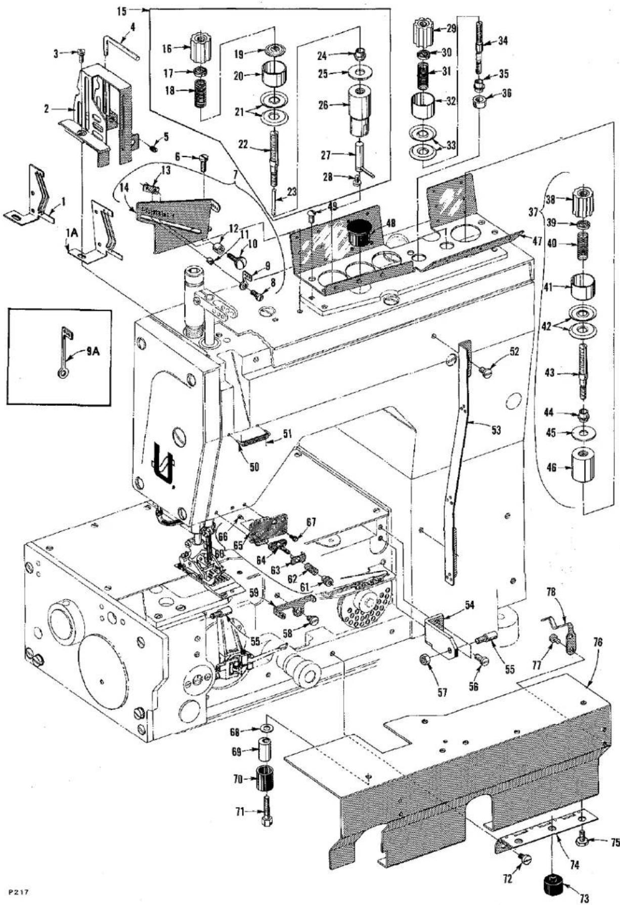
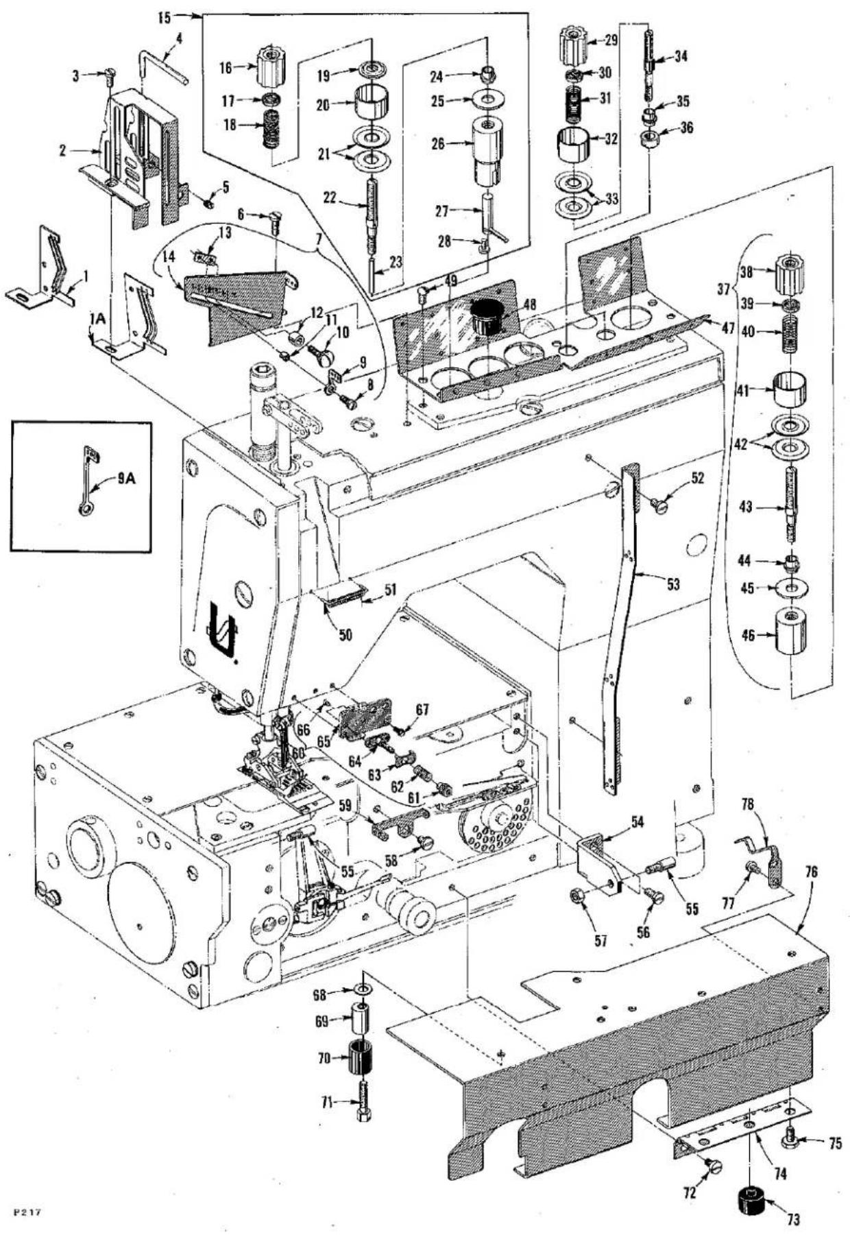
Technical diagram of a mechanical assembly with numbered components and exploded view, likely from an engineering or manufacturing context.FRONT COVER AND THREAD HANDLING PARTS
| Ref. No. | Part No. | Description | Amt. Req. |
| 1 | 50358 J | Cam, needle thread take-up, for Styles LF612K100HB-1, HC-1, MP-12, MP-16, MX-24 and 101MBE-16 | 1 |
| 1A | C50070 B | Cam, needle thread take-up, for Styles LF612K100HJ-16, HJ-18, 112HJ-16, 112HJ-18, HR-18, LF613K100HJ-8, HJ-9, HR-8, HR-9, 101HR-8, 101HR-9, 112HR-8, and 112HR-9 | 1 |
| 2 | C50054 M | Guard, needle bar eyelet | 1 |
| 3 | 22569 C | Screw | 3 |
| 4 | 50370 A | Wire, strike-off (needle thread) | 1 |
| 5 | 531 | Screw | 1 |
| 6 | 22569 C | Screw | 1 |
| 7 | 29476 PY | Needle Thread Control Assembly, for Styles LF612K100HB-1, HC-1, HJ-16, HJ-18, 112HJ-16, 112HJ-18, HR-18, MP-12, MP-16, MX-24, and 101MBE-16 | 1 |
| - | 29476 PX | Needle Thread Control Assembly, for Styles LF613K100HJ-8, HJ-9, HR-8, HR-9, 101HR-8, 101HR-9, 112HR-8 and 112HR-9 | 1 |
| 8 | 22726 L | Screw | 1 |
| - | 98 A | Screw for 158 A | 1 |
| 9 | 50358 K | Eyelet, adjustable, for 29476 PY | 1 |
| 9A | 158 A | Eylet, adjustable, for 29476 PX | 1 |
| 10 | 22837 | Screw | 1 |
| 11 | 56358 C | Washer, guide | 1 |
| 12 | 56358 D | Spacer | 1 |
| 13 | 56358 B | Block, guide | 1 |
| 14 | 50304 D | Plate, needle thread control | 1 |
| 15 | 29475 BW | Needle Thread Tension Assembly | 2 or 3 |
| 16 | C50092 S | Nut, thread tension | 2 or 3 |
| 17 | 39592 AK | Ferrule, tension spring | 2 or 3 |
| 18 | 51292 F-8 | Spring, needle thread tension | 2 or 3 |
| 19 | C50092 M | Washer, tension release | 2 or 3 |
| 20 | 56392 F | Shield, tension spring | 2 or 3 |
| 21 | 109 | Disc, tension | 4 or 6 |
| 22 | C50092 AG | Post, tension | 2 or 3 |
| 23 | C50092 J | Pin, thread tension release | 2 or 3 |
| 24 | 51292 A | Ferrule, tension post | 2 or 3 |
| 25 | C50092 R | Washer | 2 or 3 |
| 26 | 50392 B | Housing, tension assembly | 2 or 3 |
| 27 | C50092 G | Pin, tension release actuating | 2 or 3 |
| 28 | 18-799 | Screw | 2 or 3 |
| 29 | C50092 S | Nut, thread tension | 1 or 2 |
| 30 | 39592 AK | Ferrule, tension spring | 1 or 2 |
| 31 | 51292 F-2 | Spring, looper tension | 1 or 2 |
| 32 | 56392 F | Shield, tension spring | 1 or 2 |
| 33 | 109 | Disc, tension | 2 or 4 |
| 34 | 56392 E | Post, tension, looper thread | 1 or 2 |
| 35 | 51292 A | Ferrule, tension post | 1 or 2 |
| 36 | C50078 AD | Spacer, tension post | 1 or 2 |
| 37 Thru 78 | See Following Page | ||
text_image
Technical schematic diagram of an electronic device with numbered components and exploded view, including labeled parts and part numbers.FRONT COVER AND THREAD HANDLING PARTS
| Ref. No. | Part No. | Description | Amt. Req. |
| 1 thru 36 | See Preceding Page | ||
| 37 | 29475 BY | Looper Thread Tension Assembly | 1 |
| 38 | C50092 S | Nut, thread tension | 1 |
| 39 | 39592 AK | Ferrule, tension spring | 1 |
| 40 | 51292 F-2 | Spring, looper thread tension | 1 |
| 41 | 56392 F | Shield, tension spring | 1 |
| 42 | 109 | Disc, tension | 2 |
| 43 | C50092 L | Post, tension | 1 |
| 44 | 51292 A | Ferrule, tension post | 1 |
| 45 | C50092 R | Washer | 1 |
| 46 | 50392 H | Housing, tension assembly | 1 |
| 47 | 50392 J | Guide, thread | 1 |
| 48 | C50082 AH | Plug, top cover; for Styles LF612K100HB-1, HC-1, HJ-16, HJ-18, 112HJ-16, 112HJ-18, HR-18, MP-12, MP-16, MX-24, and 101MBE-16 | 1 |
| 49 | 22501 A | Screw | 5 |
| 50 | C50058 F | Wire, rubbing, needle thread | 1 |
| 51 | 50378 R | Wire, thread separating | 1 |
| 52 | 22569 D | Screw | 2 |
| 53 | 50358 | Eyelet, looper thread | 1 |
| 54 | 50332 B | Bracket, support | 1 |
| 55 | 22799 AH | Stud, latch spring | 2 |
| 56 | 22569 C | Screw | 2 |
| 57 | 35569 J | Nut | 1 |
| 58 | 22569 D | Screw | 1 |
| 59 | 50392 K | Eyelet, looper thread | 1 |
| 60 | 29475 BV | Nipper Assembly | 1 |
| 61 | 51959 D | Nut, tension | 1 |
| 62 | 15438 C | Spring | 1 |
| 63 | 57 WB | Plate, spring | 1 |
| 64 | C50092 U | Post, nipper base | 1 |
| 65 | C50044 T | Guide, needle thread | 1 |
| 66 | 22716 A | Screw | 2 |
| 67 | 605 A | Screw | 2 |
| 68 | 20 | Washer | 2 |
| 69 | 50382 T | Stop, adjustable | 2 |
| 70 | 50393 W | Bumper, rubber | 2 |
| 71 | 22519 J | Screw | 2 |
| 72 | 22569 D | Screw | 4 |
| 73 | 660-731 | Bumper, rubber | 2 |
| 74 | 50378 | Hinge, front cover | 2 |
| 75 | 22792 A | Screw | 4 |
| 76 | 50382 AA | Cover, front, for all Styles except LF612K101MBE-16 | 1 |
| - | 50382 AR | Cover, front, for Style LF612K101MBE-16 | 1 |
| 77 | 22513 | Screw | 4 |
| 78 | 50332 A | Spring, latch | 2 |
text_image
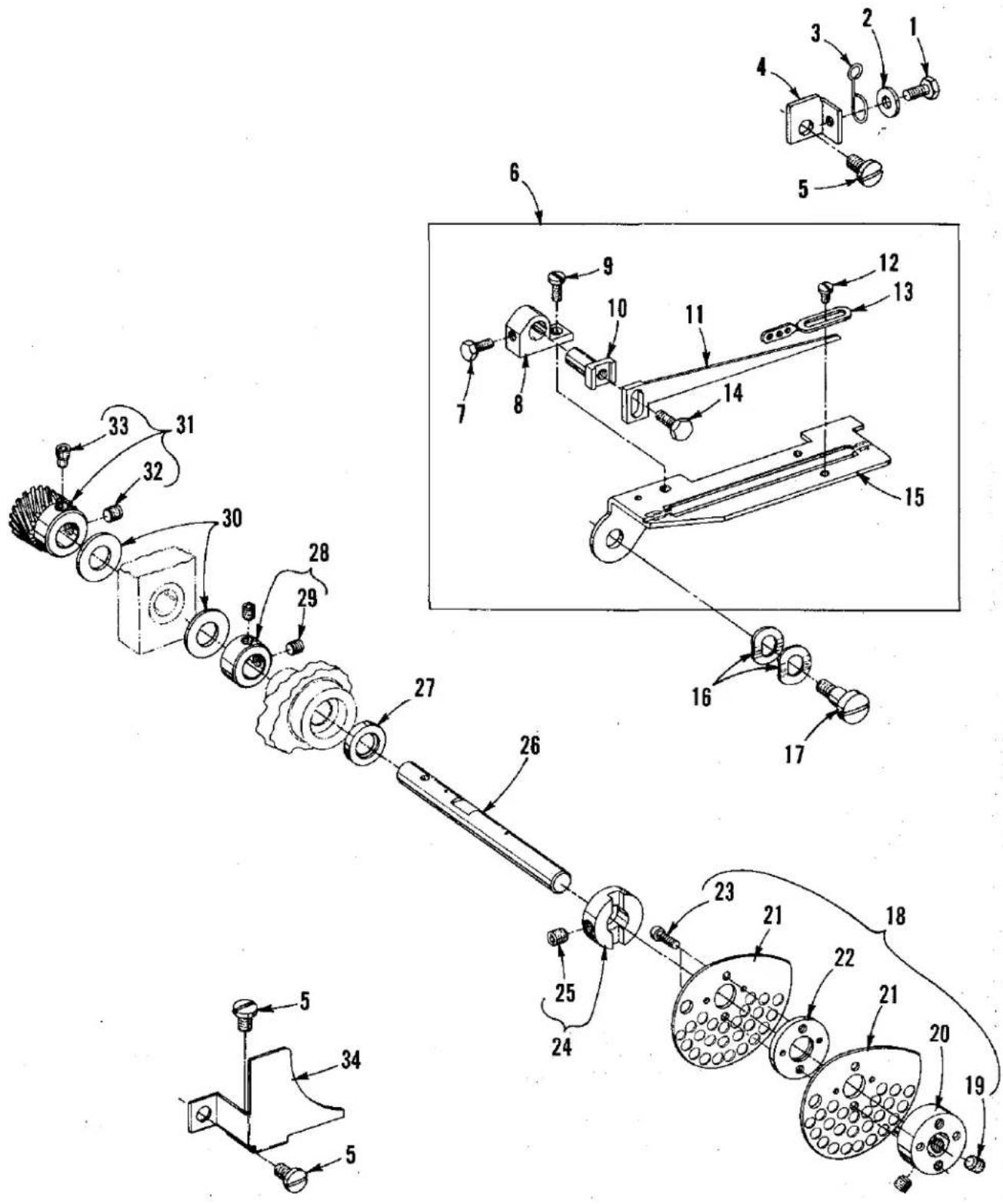
Technical diagram of a mechanical assembly with numbered components for identification and assembly reference.PULLER DRIVE
(Styles LF612K101MBE-16, LF613K101HR-8 and LF613K101HR-9)
| Ref. No. | Part No. | Description | Amt. Req. |
| 1 | C50078 L | Gear, internal | 1 |
| 2 | 660-889 | Bearing, cage | 1 |
| 3 | C50078 M | Gear | 1 |
| 4 | C50078 J | Block, slide | 1 |
| 5 | 22593 | Screw | 1 |
| 6 | C50078 N | Ring, guide | 1 |
| 7 | C50078 G | Housing, bearing | 1 |
| 8 | 22894 J | Screw | 1 |
| 9 | C50022 L | Shaft, eccentric drive | 1 |
| 10 | C50042 AC-16 | Sprocket | 1 |
| 11 | 98 | Screw | 2 |
| 12 | 660-891 C | Ring, retaining | 1 |
| 13 | 660-888 | Bearing, ball | 1 |
| 14 | 59451 F | Washer | 1 |
| 15 | 22574 D | Screw (left hand threads) | 1 |
| 16 | 660-914 | Spring, finger | 1 |
| 17 | 660-886 A | "O" Ring | 1 |
| 18 | C50082 AR | Cover | 1 |
| 19 | 22524 | Screw | 3 |
| 20 | 661-70 A | Ring, snap | 1 |
| 21 | C50078 P | Housing, eccentric | 1 |
| 22 | 660-892 C | Bearing | 1 |
| 23 | 660-886 C | "O" Ring | 1 |
| 24 | C50042 AF | Belt, timing | 1 |
| 25 | C50042 AB-16 | Sprocket | 1 |
| 26 | 98 | Screw | 4 |
| 27 | 50394 | Connector, oil tube | 1 |
| 28 | C50094 AG | Tube, oil | 1 |
| 29 | 671 F-19 | Connector | 1 |
| 30 | RM3633-1 | Fitting, oil | 1 |
| 31 | 671 F-64 | Fitting, extension | 1 |
| 32 | RM2964 B | Washer | 1 |
| 33 | 22824 B | Screw | 1 |
| 34 | 53634 C | Washer | 1 |
| 35 | C50093 CS | Protector, tube | 1 |
| 36 | 660-891 B | Ring, snap | 1 |
| 37 | 660-886 B | "O" Ring | 1 |
| 38 | C50078 H | Housing, bearing | 1 |
| 39 | 136 | Screw | 2 |
| 40 | 660-890 | Bearing, ball | 1 |
| 41 | 660-918 | Ring, retaining | 1 |
| 42 | 22825 | Screw | 3 |
| 43 | 21375 BX | Guard, belt | 1 |
| 44 | C50042 AG | Belt, timing | 1 |
| 45 | 21375 BY | Cover | 1 |
| 46 | 604 | Screw | 4 |
| *47 | C50042 Z-14 | Sprocket, puller drive | 1 |
| 48 | 22560 B | Screw | 2 |
| 49 | C50082 AP | Cover | 1 |
| 50 | 660-893 | Seal, lip | 1 |
| 51 | 660-886 A | "O" Ring | 1 |
| 52 | 660-914 | Spring | 1 |
| 53 | 22524 | Screw | 3 |
*Sprocket listed is standard with machine. Chart on page 23 lists additional sprocket variations to obtain a different stitch length
text_image
Technical diagram of a mechanical assembly with numbered components and directional arrows indicating motion or assembly steps.ROLLER PULLER
(Styles LF612K101MBE-16, LF613K101HR-8 and LF613K101HR-9)
| Ref. No. | Part No. | Description | Amt. Req. |
| 1 | C50078 F | Bracket, mounting | 1 |
| 2 | 667 C-8 | Pin, dowel | 1 |
| 3 | 51-716 BLK. | Pin, locating | 1 |
| 4 | C50077 D | Screw, adjusting | 1 |
| 5 | 88 F | Screw | 2 |
| 6 | 8372 A | Washer | 2 |
| 7 | C50077 C | Sleeve, stop | 1 |
| 8 | C50077 B | Stud, screw | 1 |
| 9 | 660-220 | "O" Ring | 1 |
| 10 | C50077 J | Washer | 2 |
| 11 | C50078 S | Block, mounting | 1 |
| 12 | 660-892 A | Bearing, needle | 2 |
| 13 | 94 | Screw | 4 |
| 14 | C50078 V | Guard, feed roller | 1 |
| 15 | 94 | Screw | 2 |
| 16 | 21375 BW | Guard, belt | 1 |
| 17 | C50042 Z-13 | Sprocket, driven, standard with machine. Chart on page 23 lists additional sprocket variations to obtain a different stitch length | 1 |
| 18 | 22560 B | Screw | 2 |
| 19 | 660-887 | Bearing, ball | 1 |
| 20 | C50042 AE | Belt, timing | 1 |
| 21 | C50022 K | Shaft, drive | 1 |
| 22 | C50078 E | Yoke, feed roller | 1 |
| 23 | 22894 E | Screw | 2 |
| 24 | 136 | Screw | 1 |
| 25 | 660-892 B | Bearing, needle | 1 |
| 26 | 51242 L | Washer | 1 |
| 27 | 28633 L | Spring | 1 |
| 28 | C50077H | Collar, puller lifting | 1 |
| 29 | 22894 AM | Screw | 1 |
| 30 | C50078 T | Block, thrust | 2 |
| 31 | 39656 A | Knife, chain cutting | 1 |
| 32 | 604 | Screw | 1 |
| 33 | C50077 K | Washer | 2 |
| 34 | C50022 N | Shaft, upper roller | 1 |
| 35 | C50042 AL | Sprocket, drive | 1 |
| 36 | 660-892 A | Bearing, needle | 2 |
| 37 | 660-219 L | Pin, roll | 1 |
| 38 | 50375 | Roller, upper puller (Steel Saw Tooth) | 1 |
| 50375 B | Roller, upper puller (Bakelite Saw Tooth) | 1 | |
| 39 | C50077 | Shaft, puller lifter | 1 |
| 40 | 660-416 | Ring, retaining | 2 |
| 41 | C50036 AJ | Pin, roller lifter | 1 |
| 42 | C50036 R | Collar, stop | 1 |
| 43 | 98 | Screw, set (required to replace screw in Ref. No. 42) | 1 |
| Ref. nos. I through 43 can be ordered under Assembly No. 29476 PW with Bakelite Saw Tooth Roller and 29476 RB with a Steel Saw Tooth Roller. | |||
| 44 | AS22 D | Screw | 1 |
| 45 | C50078 R | Plate, feed | 1 |
| 46 | 22526 | Screw | 4 |
| 47 | C50078 U | Block, bearing | 2 |
| 48 | 22894 W | Screw | 2 |
| 49 | C50074 | Shaft | 1 |
| 50 | 660-330 | Ring, retaining | 2 |
| 51 | 6042 A | Washer | 3 |
| 52 | C50076 | Roller, lower (Smooth Polyurethane) | 1 |
| 50375 D | Roller, lower (Bakelite Saw Tooth) | 1 | |
| 53 | C50078 AF-10 | Shim | 1 |
| C50078 AF-15 | Shim | 1 | |
Ref. Nos. 44 through 53 can be ordered under Assembly No. 29476 PV with Bakelite Saw Tooth Roller and 29476 PJ with Smooth Polyurethane Roller.

text_image
TORQUE TO 10-12 in. lbs. (12-14 cm/kg) TORQUE TO 14-16 in. lbs. (16-18 cm/kg)P221
NEEDLE BARS, NEEDLE BAR HEADS, LOOPERS AND LOOPER HOLDERS
| Ref. No. | Part No. | Description | Amt. Req. |
| 1 | 50358 P | Eyelet, needle bar | 1 |
| 2 | 18-71 | Screw | 1 |
| 3 | 50317 A | Bar, needle, for Styles LF612K100 HB-1, HC-1, HJ-16, HJ-18, 112HJ-16, 112HJ-18, 100HR-18, MP-12, MP-16, MX-24, and 101MBE-16 | 1 |
| 4 | C50018 L-12 | Head, needle, for Style LF612K100MP-12 | 1 |
| - | C50018 L-16 | Head, needle, for Style LF612K100MP-16 | 1 |
| - | 50318 D-24 | Head, needle, for Style LF612K100MX-24 | 1 |
| - | C50018 J-16 | Head, needle, for Styles LF612K100HJ-16, 112HJ-16and LF612K101MBE-16 | 1 |
| - | C50018 K-18 | Head, needle, for Styles LF612K100HJ-18, 112HJ-18 and 100HR-18 | 1 |
| 5 | 88B | Screw | 2 |
| 6 | 50318 B | Head, needle, for Style LF612K100HC-1 | 1 |
| - | 50318 C | Head, needle, for Style LF612K100HB-1 | 1 |
| 7 | 22743 | Screw, needle | 2 |
| 8 | 50358 G | Guide, thread | 1 |
| 9 | 73 A | Screw | 2 |
| 10 | 22580 | Screw, needle | 2 |
| 11 | 89 | Screw, spot | 1 |
| 12 | 50318 N-8 | Head, needle, for Styles LF613K100HJ-8, HR-8, 101HR-8and 112HR-8 | 1 |
| - | C50018 B-9 | Head, needle, for Styles LF613K100HJ-9, HR-9, 101HR-9and 112HR-9 | 1 |
| 13 | 22752 | Screw, center needle | 1 |
| 14 | C50017 A | Bar, needle, for Styles LF613K100HJ-8, HJ-9, HR-8, HR-9, 101HR-8, 101HR-9, 112HR-8 and 112HR-9 | 1 |
| 15 | 50 J-26 | Pin, stop | 1 |
| 16 | 50313 B | Holder, looper, for Styles LF612K100HB-1, HC-1, HJ-16, HJ-18, 112HJ-16, 112HJ-18, 100HR-18 and 101MBE-16 | 1 |
| 17 | 22565 X | Screw | 2 |
| 18 | 22575 B | Screw, adjusting | 1 |
| 19 | C50041 G | Stop | 1 |
| 20 | C50041 F | Spring, plunger | 1 |
| 21 | 22881 C | Screw | 1 |
| 22 | 50313 D | Holder, looper, for Styles LF612K100MP-12, MP-16 and MX-24 | 1 |
| 23 | 22565 X | Screw | 2 |
| 24 | 22575 B | Screw, adjusting | 1 |
| 25 | C50041 H | Collar, stop | 1 |
| 26 | 22652 J-10 | Screw | 1 |
| 27 | 53634 C | Washer | 1 |
| 28 | C50041 E | Lock, looper carrier | 1 |
| 29 | C50041 D | Lever, release | 1 |
| 30 | 538 A | Screw | 1 |
| 31 | 50313 C | Holder, looper, for Styles LF613K100HJ-8, HJ-9, HR-8, HR-9, 101HR-8, 101HR-9, 112HR-8 and 112HR-9 | 1 |
| 32 | 22565 X | Screw | 3 |
| 33 | 22575 B | Screw, adjusting | 1 |
| 34 | 51909 C | Looper, back, for Styles LF612K100HJ-16, HJ-18, 112HJ-16, 112HJ-18and 100HR-18 | 1 |
| 35 | 51508 M-18 | Looper, front, for Styles LF612K100HJ-18, 112HJ-18 and 100HR-18 | 1 |
| 36 | 51508 M-16 | Looper, front, for Styles LF612K100HJ-16 and 112HJ-16 | 1 |
| 37 | 51508 C-1 | Looper, front, for Style LF612K100HC-1 | 1 |
| 38 | 51508 G-1 | Looper, front, for Style LF612K100HB-1 | 1 |
| 39 | 51509 C | Looper, back, for Styles LF612K100HB-1 and HC-1 | 1 |
| 40 | 51909 D-8 | Looper, back, for Styles LF613K100HJ-8, HR-8, 101HR-8 and 112HR-8 | 1 |
| - | 51909 D-9 | Looper, back, for Styles LF613K100HJ-9, HR-9, 101HR-9 and 112HR-9 | 1 |
| 41 | 51909 C | Looper, middle, for all three needle machines | 1 |
| 42 | 51908 B-8 | Looper, front, for Styles LF613K100HJ-8, HR-8, 101HR-8 and 112HR-8 | 1 |
| - | 51908 B-9 | Looper, front, for Styles LF613K100HJ-9, HR-9, 101HR-9 and 112HR-9 | 1 |
| 43 | 51409 | Looper, back, for Styles LF612K100MP-12, MP-16, MX-24,and 101MBE-16 | 1 |
| 44 | 51408-16 | Looper, front, for Styles LF612K100MP-16 and LF612K101MBE-16 | 1 |
| 45 | 51408-12 | Looper, front, for Style LF612K100MP-12 | 1 |
| 46 | 51408-24 | Looper, front, for Style LF612K100MX-24 | 1 |

text_image
Technical diagram of a sewing machine with numbered parts for identification and assembly reference.
text_image
Technical diagram of an electrical switch assembly with numbered components and exploded view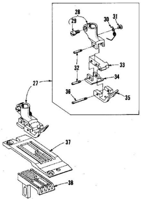
text_image
Technical diagram of a mechanical assembly with numbered parts, showing exploded and assembled views.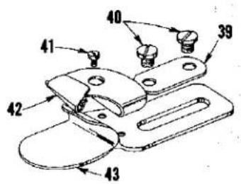
text_image
40 39 41 42 43P187
SEWING COMBINATIONS
| Ref. No. | Part No. | Description | Amt. Req. |
| 1 | 56520 | Presser Foot Assembly, for Styles LF612K100HB-1 and HC-1 | 1 |
| 2 | 51530 D | Shank, presser foot | 1 |
| 3 | 91 | Screw | 1 |
| 4 | 51530 G | Spring | 1 |
| 5 | 1740 | Pin | 1 |
| 6 | 51530 F | Plunger | 1 |
| 7 | 56530 A | Section, yielding | 1 |
| 8 | 56530 | Bottom, presser foot | 1 |
| 9 | 22799 E | Screw, hinge | 1 |
| 10 | 52930 AC | Knife, chain cutting | 1 |
| 11 | 91 A | Screw | 1 |
| 12 | 56524 B-1 | Throat Plate, for Style LF612K100HB-1 | 1 |
| - | 56528 C-1 | Throat Plate, for Style LF612K100HC-1 | 1 |
| 13 | 56505 | Feed Dog, for Styles LF612K100HB-1 and HC-1 | 1 |
| 14 | C50020 E-18 | Presser Foot Assembly, for Styles LF612K100HJ-18 and 112HJ-18 | 1 |
| - | C50020 F-16 | Presser Foot Assembly, for Styles LF612K100HJ-16 and 112HJ-16 | 1 |
| 15 | 35830 B | Shank, presser foot | 1 |
| 16 | 91 D | Screw | 1 |
| 17 | 73 A | Screw | 1 |
| 18 | 35830 H | Spring | 1 |
| 19 | 22845 A | Screw | 6 |
| 20 | 22599 | Screw | 1 |
| 21 | 35830 K | Spring | 1 |
| 22 | 35830 C | Yoke | 1 |
| 23 | C50030 AE | Bottom, presser foot (front section) for Styles LF612K100HJ-18 and 112HJ-18 | 1 |
| - | C50030 AD | Bottom, presser foot (front section)for Styles LF612K100HJ-16 and 112HJ-16 | 1 |
| 24 | 56930 | Bottom, presser foot (rear section) for Styles LF612K100HJ-18 and 112HJ-18 | 1 |
| - | C50030 AC | Bottom, presser foot (rear section) for Styles LF612K100HJ-16 and 112HJ-16 | 1 |
| 25 | C50024 R-16 | Throat Plate, for Styles LF612K100HJ-16 and 112HJ-16 | 1 |
| - | C50024 Y-18 | Throat Plate, for Styles LF612K100HJ-18 and 112HJ-18 | 1 |
| 26 | C50005 N | Feed Dog, for Styles LF612K100HJ-16, HJ-18, 112HJ-16 and 112HJ-18 | 1 |
| 27 | 51520 BR-18 | Presser Foot Assembly, for Styles LF612K100HR-18 | 1 |
| 28 | 35730 AD | Shank, presser foot | 1 |
| 29 | 91 | Screw | 1 |
| 30 | 35730 AE | Spring | 1 |
| 31 | 73 A | Screw | 1 |
| 32 | 22799 G | Screw, hinge | 2 |
| 33 | 35730 AC | Section, hinged | 1 |
| 34 | 51530 J | Bottom, presser foot (rear section) | 1 |
| 35 | 51530 BR-18 | Bottom, presser foot (front section) | 1 |
| 36 | 22799 C | Screw, hinge | 1 |
| 37 | C51524 BR-18 | Throat Plate, for Style LF612K100HR-18 | 1 |
| 38 | 51505 BR-18 | Feed Dog, for Style LF612K100HR-18 | 1 |
| 39 | 23425 V | Plate, washer | 1 |
| 40 | 25 C | Screw | 2 |
| 41 | 28 | Screw | 1 |
| 42 | 23421U-16-3/32 | Scroll, upper, for Styles LF612K100HJ-16 and 112HJ-16 | 1 |
| - | 23421 Y-18-3/32 | Scroll, upper, for Styles LF612K100HJ-18, 112HJ-18 and 100HR-18 | 1 |
| 43 | 23422 Y-3/32 | Lower Scroll and Base, for Styles LF612K100HJ-16, 112HJ-16, HJ-18, 112HJ-18 and 100HR-18 | 1 |
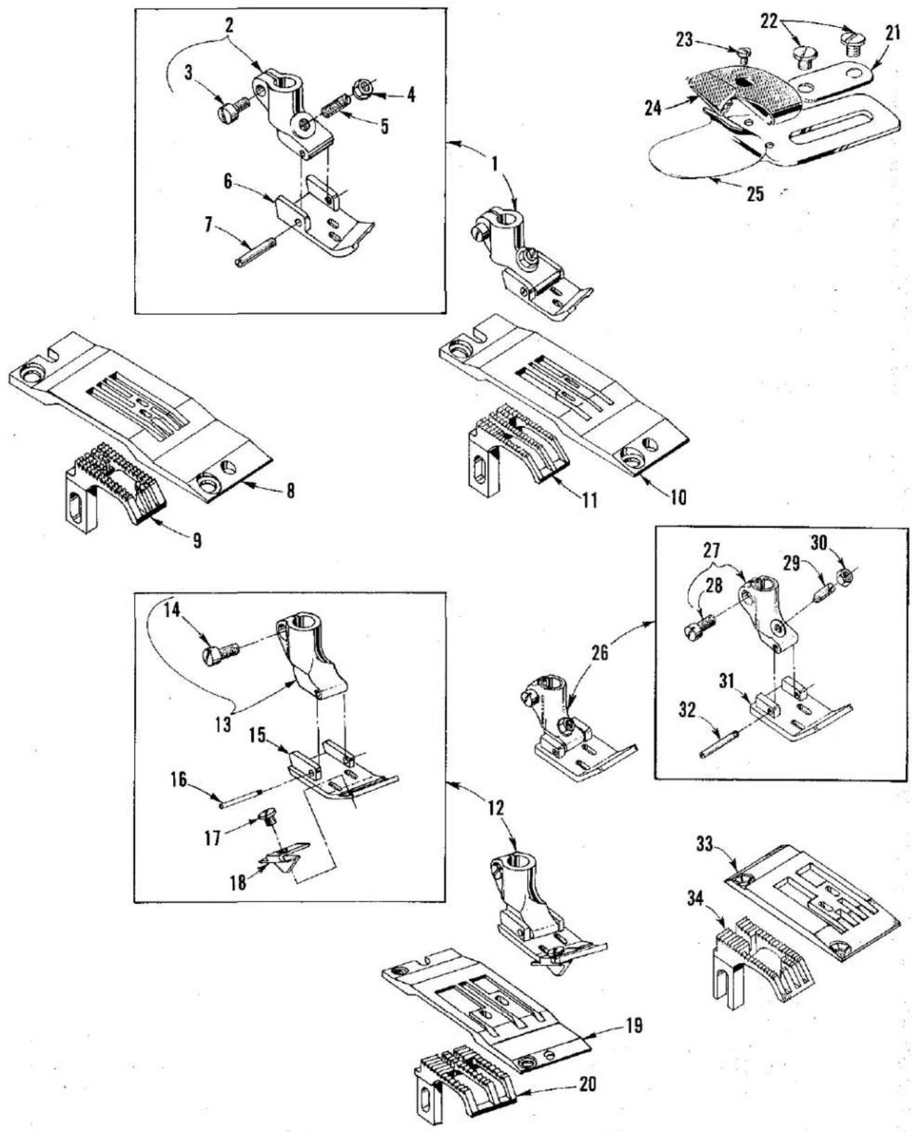
SEWING COMBINATIONS
| Ref. No. | Part No. | Description | Amt. Req. |
| 1 | 51420-12 | Presser Foot Assembly, for Style LF612K100MP-12 | 1 |
| - | 51420-16 | Presser Foot Assembly, for Style LF612K100MP-16 | 1 |
| 2 | 51430 D | Shank, presser foot | 1 |
| 3 | 91 | Screw | 1 |
| 4 | 51430 F | Nut, adjusting | 1 |
| 5 | 22840 A | Screw, adjusting | 1 |
| 6 | 51430 A-12 | Bottom, presser foot, for Style LF612K100MP-12 | 1 |
| - | 51430 A-16 | Bottom, presser foot, for Style LF612K100MP-16 | 1 |
| 7 | 22799 B | Screw, hinge | 1 |
| 8 | 51424 A-12 | Throat Plate, for Style LF612K100MP-12 | 1 |
| 9 | 51405 A-10 | Feed Dog, for Style LF612K100MP-12 | 1 |
| 10 | C51424-16 | Throat Plate, for Style LF612K100MP-16 | 1 |
| 11 | 51405-16 | Feed Dog, for Style LF612K100MP-16 | 1 |
| 12 | 51420 K-24 | Presser Foot Assembly, for Style LF612K100MX-24 | 1 |
| 13 | 51430 B | Shank, presser foot | 1 |
| 14 | 91 | Screw | 1 |
| 15 | 51430 K-24 | Bottom, presser foot | 1 |
| 16 | 22799 B | Screw, hinge | 1 |
| 17 | 187 A | Screw | 1 |
| 18 | 53530 E | Guide | 1 |
| 19 | 51424 K-24 | Throat Plate, for Style LF612K100MX-24 | 1 |
| 20 | 51405 K-26 | Feed Dog, for Style LF612K100MX-24 | 1 |
| 21 | 23425 V | Plate, washer | 1 |
| 22 | 25 C | Screw | 2 |
| 23 | 28 | Screw | 1 |
| 24 | 23421 U-12-1/16 | Scroll, upper, for Style LF612K100MP-12 | 1 |
| - | 23421 U-16-1/16 | Scroll, upper, for Style LF612K100MP-16 | 1 |
| 25 | 23422 U-1/16 | Lower Scroll and Base, for Styles LF612K100MP-12 and MP-16 | 1 |
| 26 | 7420 AG4-1/2 | Presser Foot Assembly, for Style LF612K101MBE-16 | 1 |
| 27 | 51430 D | Shank, presser foot | 1 |
| 28 | 91 | Screw | 1 |
| 29 | 22840 A | Screw | 1 |
| 30 | 51430 F | Nut | 1 |
| 31 | 65-266 | Bottom, presser foot | 1 |
| 32 | 22799 F | Screw, hinge | 1 |
| 33 | C7528 H-4-1/2 | Throat Plate, for Style LF612K101MBE-16 | 1 |
| 34 | 7405 U-4-1/2 | Feed Dog, for Style LF612K101MBE-16 | 1 |
SEWING COMBINATIONS
| Ref.No. | PartNo. | Description | Amt.Req. |
| 1 | 50320 M-8 | Presser Foot Assembly, for Style LF613K100HJ-8 | 1 |
| - | 56920 A-9 | Presser Foot Assembly, for Style LF613K100HJ-9 | 1 |
| 2 | 35830 B | Shank, presser foot | 1 |
| 3 | 91 D | Screw | 1 |
| 4 | 73 A | Screw | 1 |
| 5 | 35830 H | Spring | 1 |
| 6 | 22845 A | Screw | 6 |
| 7 | 50330 BF-8 | Bottom, presser foot (rear section) for Style LF613K100HJ-8 | 1 |
| - | 56930 | Bottom, presser foot (rear section) for Style LF613K100HJ-9 | 1 |
| 8 | 22599 | Screw | 1 |
| 9 | 35830 K | Spring | 1 |
| 10 | 35830 C | Yoke | 1 |
| 11 | 35830 R-8 | Bottom, presser foot (front section) for Style LF613K100HJ-8 | 1 |
| - | 35830 R-9 | Bottom, presser foot (front section) for Style LF613K100HJ-9 | 1 |
| 12 | 50324 N-8 | Throat Plate, for Style LF613K100HJ-8 | 1 |
| - | C56924 A-9 | Throat Plate, for Style LF613K100HJ-9 | 1 |
| 13 | 56905 A-9 | Feed Dog, for Styles LF613K100HJ-8 and LF613K100HJ-9 | 1 |
| 14 | 25 C | Screw | 2 |
| 15 | 23425 V | Plate, washer | 1 |
| 16 | 28 | Screw | 1 |
| 17 | 23421 U-16-3/32 | Scroll, upper, for Style LF613K100HJ-8 | 1 |
| - | 23421 U-16-1/8 | Scroll, upper, for Styles LF613K100HR-8, 101HR-8 and 112HR-8 | 1 |
| - | 23421 U-18-3/32 | Scroll, upper, for Style LF613K100HJ-9 | 1 |
| 18 | 23422 BZ-3/32 | Lower Scroll and Base, for Styles LF613K100HJ-8 and HJ-9 | 1 |
| - | 23422 BZ-1/8 | Lower Scroll and Base for Styles LF613K100HR-8, 101HR-8and 112HR-8 | 1 |
| 19 | 56920 R-9 | Presser Foot Assembly, for Styles LF613K100HR-9, 101HR-9and 112HR-9 | 1 |
| - | 50320 N-8 | Presser Foot Assembly, for Styles LF613K100HR-8, 101HR-8and 112HR-8 | 1 |
| 20 | 35830 B | Shank, presser foot | 1 |
| 21 | 91 D | Screw | 1 |
| 22 | 73 A | Screw | 1 |
| 23 | 35830 H | Spring | 1 |
| 24 | 22845 A | Screw | 6 |
| 25 | 56930 B | Bottom, presser foot (rear section) for Styles LF613K100HR-9,101HR-9 and 112HR-9 | 1 |
| - | 50330 BG-8 | Bottom, presser foot (rear section) for Styles LF613K100HR-8,101HR-8 and 112HR-8 | 1 |
| 26 | 22599 | Screw | 1 |
| 27 | 35830 K | Spring | 1 |
| 28 | 35830 C | Yoke | 1 |
| 29 | 35830 R-9 | Bottom, presser foot (front section) for Styles LF613K100HR-9,101HR-9 and 112HR-9 | 1 |
| - | 50330 BE-8 | Bottom, presser foot (front section) for Styles LF613K100HR-8,101HR-8 and 112HR-8 | 1 |
| 30 | 50324 P-8 | Throat Plate, for Styles LF613K100HR-8 and 101HR-8 | 1 |
| - | 50324 R-8 | Throat Plate, for Style LF613K112HR-8 | 1 |
| - | C56924 R-9 | Throat Plate, for Styles LF613K100HR-9 and 101HR-9 | 1 |
| - | C50024 Y-9 | Throat Plate, for Style LF613K112HR-9 | 1 |
| 31 | 56905 R-9 | Feed Dog, for Styles LF613K100HR-8, 101HR-8, 112HR-8,100HR-9, 101HR-9 and 112HR-9 | 1 |
| 32 | 23420 S-9-1/8 | Folder Assembly, for Styles LF613K100HR-9, 101HR-9 and 112HR-9 | 1 |
| 33 | 28 | Screw | 1 |
| 34 | 23421 S-9-1/8 | Scroll, upper | 1 |
| 35 | 23422 AY-18-1/8 | Scroll, lower | 1 |
| 36 | 22760 A | Screw | 2 |
| 37 | 23424 S | Spring | 1 |
| 38 | 23423 S | Base | 1 |
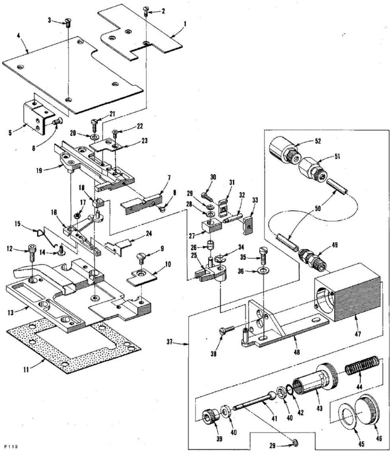
text_image
Technical diagram of a mechanical assembly with numbered components and exploded viewsPOWER "AIR KLIPP" CHAIN CUTTER AND RELATED PARTS
(Styles LF612K112HJ-16, HJ-18, LF613K112HR-8 and HR-9)
| Ref. No. | Part No. | Description | Amt. Req. |
| 1 | 50382 AS | Cover, suction tube | 1 |
| 2 | 99312 A | Screw | 3 |
| 3 | 22525 E | Screw | 4 |
| 4 | 50301 AC | Plate, cloth (left) | 1 |
| 5 | 50332 E | Bracket | 1 |
| 6 | 22526 | Screw | 2 |
| 7 | 99677 UA | Inlet, thread, for Styles LF612K112HJ-16 and LF612K112HJ-18 | 1 |
| 99677 TB | Inlet, thread, for Styles LF613K112HR-8 and LF613K112HR-9 | 1 | |
| 8 | 77 F | Screw | 1 |
| 9 | 22569 F | Screw | 1 |
| 10 | 50382 DB | Cover, plate | 1 |
| 11 | 50382 BT | Gasket | 1 |
| 12 | 22653 B-8 | Screw | 6 |
| V29944 D | Power "Air Klipp" Assembly (complete) | 1 | |
| 13 | 99679 UB | Cover | 1 |
| 14 | 99372 A | Screw, adjusting | 1 |
| 15 | 99697 TA | Spring | 1 |
| 16 | 99666 TB | Lever, knife | 1 |
| 17 | 99322 | Nut | 1 |
| 18 | 99672 UE | Block, sliding | 1 |
| 19 | 99691 TA | Housing, chain cutter | 1 |
| 20 | 80265 | Washer | 2 |
| 21 | 22729 J | Screw | 2 |
| 22 | 95435 A | Screw | 2 |
| 23 | 99670 TH | Knife, upper | 1 |
| 24 | 99669 TH | Knife, lower | 1 |
| 25 | 99672 UD | Lever | 1 |
| 26 | 99672 TC | Insert, plastic | 1 |
| 27 | 671 H-4D | Connection | 1 |
| 28 | 95954 | Washer | 1 |
| 29 | 96280 | Ring, retaining | 3 |
| 30 | 22562 A | Screw | 1 |
| 31 | 99672 UB-2 | Clamp,(rear) | 1 |
| 32 | H5100 D | Screw, stud | 1 |
| 33 | 99672 UB-1 | Clamp (front) | 1 |
| 34 | 96275 | Ring, retaining | 1 |
| 35 | 22517 | Screw | 2 |
| 36 | 80557 | Washer | 2 |
| 37 | 671 H-4 | Air-Motor Assembly | 1 |
| 38 | 22585 | Screw | 2 |
| 39 | 671 H-1E | Screw, plug | 1 |
| 40 | 99646 BA | Collar, thrust | 2 |
| 41 | 671 H-4C | Rod, piston | 1 |
| 42 | 660-206 | "O" Ring | 1 |
| 43 | 671 H-1A | Piston | 1 |
| 44 | 660-753 | Spring | 1 |
| 45 | 671 H-1F | Washer, bumper | 1 |
| 46 | 671 H-1D | Screw, plug | 1 |
| 47 | 671 H-2A | Housing | 1 |
| 48 | 671 H-4A | Bracket, housing | 1 |
| 49 | 660-400 | Fitting, straight | 2 |
| 50 | 99675 G1000 | Tubing, plastic | 1 |
| 51 | 999-126 G | Connector, straight | 1 |
| 52 | 999-140 C | Muffler | 1 |
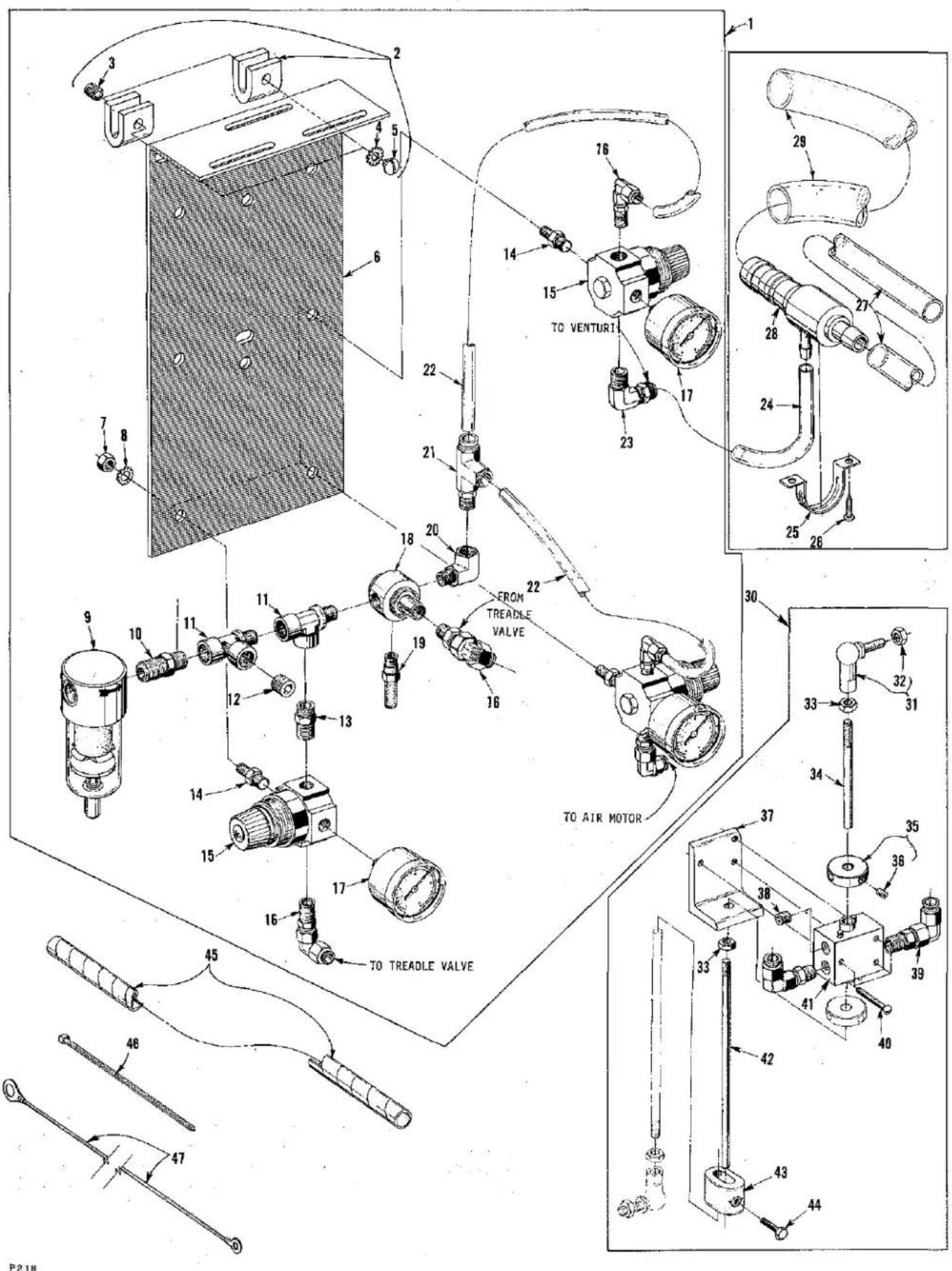
text_image
Technical diagram of a mechanical assembly with numbered parts and labeled parts such as venturi, air motor, and treadle valve.PNEUMATIC CONTROLS
(Styles LF612K112HJ-16, HJ-18, LF613K112HR-8 and HR-9)
| Ref. No. | Part No. | Description | Amt. Req. |
| 1 | 29480 ADM | Pneumatic Control Board Assembly | 1 |
| 2 | 661-3 | Clamp, mounting | 2 |
| 3 | 22650 CF-6 | Screw, set | 2 |
| 4 | 652 B-16 | Washer, lock | 2 |
| 5 | 22635 D-16 | Screw | 2 |
| 6 | B5032 R | Bracket, mounting | 1 |
| 7 | 11635 B | Nut | 3 |
| 8 | 652 B-20 | Washer, lock | 3 |
| 9 | 671 D-5 | Filter | 1 |
| 10 | RM3320-1 | Reducer | 1 |
| 11 | RM2850 D | Tee, pipe | 2 |
| 12 | 22571 F | Screw, plug | 1 |
| 13 | RM3287-2 | Nipple, hex | 1 |
| 14 | 671 C-16 | Stud, mounting | 3 |
| 15 | 671 D-9 | Regulator | 3 |
| 16 | 671 F-69 | Fitting, swivel, 90 degree | 5 |
| 17 | 671 D-15 | Gauge | 3 |
| 18 | RM4098-1 | Valve, pilot | 1 |
| 19 | 660-403 | Muffler | 1 |
| 20 | RM2881-1 | Elbow, 90 degree | 1 |
| 21 | 671 F-94 | Tee, run | 1 |
| 22 | 660-392 | Tube, air, 1/4 inch (6.35mm) | 2 |
| 23 | 671 F-3 | Fitting, tube, 3/8 inch (9.52mm) | 1 |
| 24 | 671 B-3 | Tube, venturi (air supply) | 1 |
| 25 | 998-332 | Holder, venturi | 1 |
| 26 | RM2719-1 | Screw, wood | 2 |
| 27 | 671 B-12 | Tube, suction | 1 |
| 28 | 671 D-2 | Venturi | 1 |
| 29 | 671 B-11 | Tube, discharge | 1 |
| 30 | 29480 ACD | Treadle Valve Assembly | 1 |
| 31 | 999-146 | Link | 2 |
| 32 | 95250 | Nut | 2 |
| 33 | 95250 | Nut | 3 |
| 34 | 99563 A-75 | Rod, pitman | 1 |
| 35 | C50036 AS | Collar, acuating | 2 |
| 36 | 22894 R | Screw | 2 |
| 37 | 671-135 | Bracket, mounting | 1 |
| 38 | 22571 F | Screw, plug | 1 |
| 39 | 671 F-69 | Fitting, swivel, 90 degree | 2 |
| 40 | SC191 | Screw | 3 |
| 41 | 671-134 | Body, valve | 1 |
| 42 | 99563 A-130 | Rod, pitman | 2 |
| 43 | G28562 A | Connector, rod (pitman) | 1 |
| 44 | 95051 | Screw | 1 |
| 45 | RM3832-1 | Wrap, harness | 1 |
| 46 | RM2871 B | Tie | 4 |
| 47 | 670 E-256 | Wire, ground | 1 |
| 671 F-88 | Fitting, barb (air supply, not shown) | 1 |
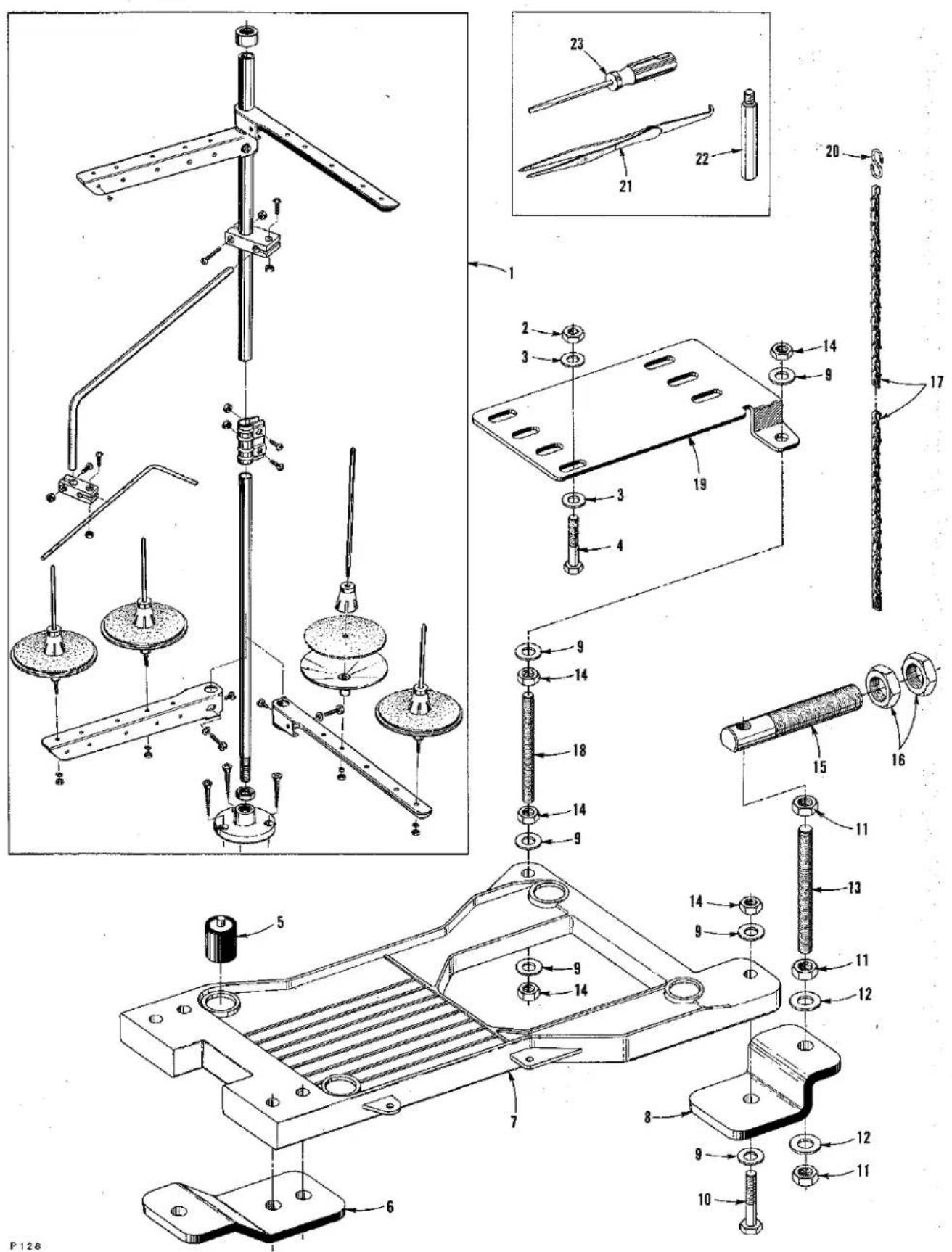
text_image
Technical diagram of a mechanical assembly with numbered parts and exploded views, likely from an engineering manual.THREAD STAND AND ACCESSORIES
| Ref. No. | Part No. | Description | Amt. Req. |
| 1 | 21101 W-4 | Thread Stand Assembly, for Styles LF612K100HB-1, HC-1, HJ-16, HJ-18, HR-18, MP-12, MP-16, MX-24, 101MBE-16, 112HJ-16 and 112HJ-18 | 1 |
| - | 21101 W-6 | Thread Stand Assembly, for Styles LF613K100HJ-8, HJ-9, HR-8, HR-9, 101HR-8, 101HR-9, 112HR-8 and 112HR-9 | 1 |
| 2 | 50335 T | Nut | 1 |
| 3 | 652-16 | Washer | 6 |
| 4 | 22788 H | Bolt | 3 |
| 5 | 35095 B | Isolator | 4 |
| 6 | 21374 BP | Support | 2 |
| 7 | 21374 AG | Cradle, machine | 1 |
| 8 | 21374 BR | Support | 1 |
| 9 | RM3293-3 | Washer | 14 |
| 10 | 22641 | Bolt | 5 |
| 11 | RM3211-4 | Nut | 9 |
| 12 | 652 P-36 | Washer | 9 |
| 13 | 21374 BS | Rod, threaded | 3 |
| 14 | RM3211-3 | Nut | 9 |
| 15 | 21374 BT | Rod | 3 |
| 16 | 651 M | Nut | 6 |
| 17 | 421 D-42 | Chain, presser foot lifter | 1 |
| 18 | 21371 PY-32 | Rod, threaded | 1 |
| 19 | 21374 BB | Bracket, motor mounting | 1 |
| 20 | 660-264 | Hook, "S" | 2 |
| 21 | 660-240 | Tweezer, thread | 1 |
| 22 | 22841 M | Stand, machine | 4 |
| 23 | 21207 B | Screwdriver | 1 |
| 28604 R | Container of oil, 16 ounces (455ml.), Spec. 175, (not shown) | 1 | |
| 28604 S | Container of oil, 32 ounces (946ml.), Spec. 175, (not shown) | 1 | |
| 660-457 | Dust Cover (not shown) | 1 | |
| 22788 J | Metric Bolt (not shown) | 2 |
NUMERCIAL INDEX OF PARTS
| Part No. | Page No. |
| 109 | 47,49 |
| 11635 B | 65 |
| 12934 A | 33,43 |
| 136 | 51,53 |
| 136 A | 31 |
| 15438 C | 49 |
| 158 A | 47 |
| 1740 | 57 |
| 18-71 | 55 |
| 18-799 | 47 |
| 187 A | 59 |
| 20 | 49 |
| 21101 W-4 | 67 |
| 21101 W-6 | 67 |
| 21207 B | 67 |
| 21371 PY-32 | 67 |
| 21374 AG | 67 |
| 21374 BB | 67 |
| 21374 BP | 67 |
| 21374 BR | 67 |
| 21374 BS | 67 |
| 21374 BT | 67 |
| 21375 BW | 53 |
| 21375 BX | 51 |
| 21375 BY | 51 |
| 22501 A | 49 |
| 22513 | 49 |
| 22517 | 33,63 |
| 22519 H | 41 |
| 22519 J | 49 |
| 22519 K | 43 |
| 22524 | 51 |
| 22524 B | 41 |
| 22525 E | 33,63 |
| 22526 | 53,63 |
| 22526 H | 33 |
| 22539 G | 31 |
| 22539 V | 41 |
| 22541 | 29 |
| 22541 A | 33 |
| 22541 C | 33 |
| 22557 J | 43 |
| 22560 B | 41,51,53 |
| 22562 A | 37,39,63 |
| 22565 X | 55 |
| 22569 C | 43,47,49 |
| 22569 D | 33,35,45,49 |
| 22569 F | 31,63 |
| 22569 G | 39 |
| 22569 M | 33 |
| 22570 | 35 |
| 22571 D | 41 |
| 22571 E | 29 |
| 22571 F | 27,65 |
| 22571 H | 35 |
| 22571 J | 29 |
| 22574 D | 51 |
| 22575 B | 55 |
| 22580 | 55 |
| 22585 | 63 |
| 22586 U | 29,31 |
| 22587 N | 33 |
| 22588 A | 45 |
| 22588 S | 45 |
| 22591 | 37,41 |
| 22591 A | 41 |
| 22593 | 51 |
| 22596 H | 37,41,43 |
| 22599 | 57,61 |
| PartNo. | PageNo. |
| 22617 J-16 | 41 |
| 22635 D-16 | 65 |
| 22637 P-32 | 41 |
| 22641 | 67 |
| 22650 CD-6 | 39 |
| 22650 CF-6 | 65 |
| 22651 CD-4 | 37 |
| 22652 A-6 | 29 |
| 22652 A-8 | 39 |
| 22652 J-10 | 55 |
| 22653 B-36 | 27 |
| 22653 B-8 | 35,63 |
| 22653 J-8 | 39 |
| 22655 B-7 | 37 |
| 22706 C | 37 |
| 22714 C | 41 |
| 22716 A | 49 |
| 22720 A | 27 |
| 22720 C | 37 |
| 22726 L | 47 |
| 22729 | 39 |
| 22729 J | 63 |
| 22729 L | 41 |
| 22733 | 31 |
| 22743 | 55 |
| 22752 | 55 |
| 22758 | 43 |
| 22760 A | 61 |
| 22764 | 39 |
| 22764 A | 41 |
| 22764 C | 31 |
| 22768 | 45 |
| 22781 | 45 |
| 22788 H | 67 |
| 22788 J | 67 |
| 22792 A | 49 |
| 22799 AH | 33,49 |
| 22799 B | 59 |
| 22799 C | 57 |
| 22799 E | 57 |
| 22799 F | 59 |
| 22799 G | 57 |
| 22824 B | 51 |
| 22825 | 51 |
| 22830 | 39 |
| 22837 | 47 |
| 22839 | 33 |
| 22840 A | 59 |
| 22840 C | 43 |
| 22841 M | 29,67 |
| 22841 N | 33 |
| 22845 A | 57,61 |
| 22861 C | 33 |
| 22874 | 43 |
| 22881 C | 55 |
| 22882 | 43 |
| 22883 B | 33,35 |
| 22894 AB | 41 |
| 22894 AD | 37,39 |
| 22894 AE | 39 |
| 22894 AF | 39 |
| 22894 AM | 53 |
| 22894 AT | 45 |
| 22894 C | 27,31,35,37,39,41,45 |
| 22894 E | 53 |
| 22894 J | 29,33,37,41,51 |
| 22894 K | 39 |
| PartNo. | PageNo. |
| 22894 L | 43 |
| 22894 P | 43 |
| 22894 R | 65 |
| 22894 W | 43,53 |
| 22894 X | 39 |
| 23420 S-9-1/8 | 61 |
| 23421 S-9-1/8 | 61 |
| 23421 U-12-1/16 | 59 |
| 23421 U-16-1/8 | 61 |
| 23421 U-16-1/16 | 59 |
| 23421 U-16-3/32 | 57,61 |
| 23421 U-18-3/32 | 61 |
| 23421 Y-18-3/32 | 57 |
| 23422 AY-18-1/8 | 61 |
| 23422 BZ-3/32 | 61 |
| 23422 BZ-1/8 | 61 |
| 23422 U-1/16 | 59 |
| 23422 Y-3/32 | 57 |
| 23423 S | 61 |
| 23424 S | 61 |
| 23425 V | 57,59,61 |
| 25 C | 57,59,61 |
| 25 S | 37,39 |
| 258 | 29,37 |
| 28 | 57,59,61 |
| 28604 R | 67 |
| 28604 S | 67 |
| 28619 | 29 |
| 28633 L | 53 |
| 29105 AT | 39 |
| 29126 EV | 41 |
| 29126 FB | 41 |
| 29192 AE | 39 |
| 29475 BV | 49 |
| 29475 BW | 47 |
| 29475 BY | 49 |
| 29476 PX | 47 |
| 29476 PY | 47 |
| 29480 ACD | 65 |
| 29480 ADM | 65 |
| 35021 | 39 |
| 35021 B | 39 |
| 35034 M | 41 |
| 35034 N | 41 |
| 35034 X | 41 |
| 35036 AB | 31 |
| 35036 AE | 33 |
| 35036 AP | 41 |
| 35036 AZ | 41 |
| 35036 BN | 41 |
| 35036 F | 41 |
| 35036 X | 27 |
| 35039 A | 29 |
| 35040 B-15 | 41 |
| 35040 B-22 | 41 |
| 35040 B-25 | 41 |
| 35042 C | 37 |
| 35055 V | 39 |
| 35082 E | 35 |
| 35082 F | 35 |
| 35091 A | 37 |
| 35093 BL | 27 |
| 35093 F | 29 |
| 35093 H | 29 |
| 35093 J | 29 |
| 35093 P | 37 |
| 35094 A | 27 |
| 35095 B | 67 |
| 35569 J | 49 |
| 35730 AC | 57 |
NUMERICAL INDEX OF PARTS
| Part No. | Page No. |
| 35730 AD | 57 |
| 35730 AE | 57 |
| 35830 B | 57,61 |
| 35830 C | 57,61 |
| 35830 H | 57,61 |
| 35830 K | 57,61 |
| 35830 R-8 | 61 |
| 35830 R-9 | 61 |
| 37-70 BLK | 35 |
| 39592 AK | 47,49 |
| 39656 A | 53 |
| 41350 X | 27,29,31,37 |
| 421 D-42 | 67 |
| 50 J-26 | 55 |
| 50301 | 35 |
| 50301 AC | 63 |
| 50301 AD | 35 |
| 50301 AE | 35 |
| 50301 B | 35 |
| 50301 R | 35 |
| 50304 A | 45 |
| 50304 D | 47 |
| 50313 B | 55 |
| 50313 C | 55 |
| 50313 D | 55 |
| 50314 A | 39 |
| 50314 B | 39 |
| 50317 A | 55 |
| 50318 B | 55 |
| 50318 C | 55 |
| 50318 D-24 | 55 |
| 50318 N-8 | 55 |
| 50320 M-8 | 61 |
| 50320 N-8 | 61 |
| 50322 AB | 39 |
| 50322 B | 43 |
| 50322 C | 43 |
| 50322 F | 43 |
| 50322 K | 41 |
| 50323 | 45 |
| 50323 B | 45 |
| 50323 C | 45 |
| 50323 L | 45 |
| 50324 N-8 | 61 |
| 50324 P-8 | 61 |
| 50324 R-8 | 61 |
| 50325 H | 39 |
| 50325 K | 39 |
| 50330 BE-8 | 61 |
| 50330 BF-8 | 61 |
| 50330 BG-8 | 61 |
| 50332 | 45 |
| 50332 A | 49 |
| 50332 B | 49 |
| 50332 E | 63 |
| 50334 A | 41 |
| 50334 AA | 41 |
| 50334 AB | 41 |
| 50334 B | 41 |
| 50334 C | 41 |
| 50334 F | 41 |
| 50334 K | 41 |
| 50334 W | 41 |
| 50334 Y | 41 |
| 50335 | 41 |
| 50335 A | 41 |
| 50335 C | 41 |
| 50335 D | 41 |
| 50335 E | 41 |
| Part No. | Page No. |
| 50335 L | 41 |
| 50335 T | 67 |
| 50335 Z | 41 |
| 50336 C | 41 |
| 50336 D | 41 |
| 50336 L | 33 |
| 50339 | 39 |
| 50339 B | 31,35 |
| 50342 A | 39 |
| 50342 AB | 37 |
| 50342 AC | 37 |
| 50342 AD | 37 |
| 50342 AF | 37 |
| 50342 AM | 45 |
| 50342 AN | 45 |
| 50342 B | 39 |
| 50342 D | 39 |
| 50342 H | 39 |
| 50342 R | 37 |
| 50342 U | 37 |
| 50342 V | 37 |
| 50342 W | 37 |
| 50342 X | 37 |
| 50342 Y | 37 |
| 50343 | 39 |
| 50344 B | 31 |
| 50344 C | 39 |
| 50344 E | 31 |
| 50344 H | 45 |
| 50344 K | 31 |
| 50344 L | 31 |
| 50344 V | 31 |
| 50344 X | 31 |
| 50354 D | 31 |
| 50354 E | 31 |
| 50355 | 41 |
| 50355 AE | 37 |
| 50355 H | 37 |
| 50355 L | 31 |
| 50355 P | 37 |
| 50355 T | 37 |
| 50356 A | 43 |
| 50357 | 45 |
| 50357 A | 45 |
| 50357 D | 45 |
| 50357 F | 45 |
| 50357 K | 45 |
| 50358 | 49 |
| 50358 G | 55 |
| 50358 H | 45 |
| 50358 J | 47 |
| 50358 K | 47 |
| 50358 P | 55 |
| 50367 | 43 |
| 50367 A | 43 |
| 50367 B | 43 |
| 50367 E | 43 |
| 50368 | 39 |
| 50368 A | 39 |
| 50368 B | 31 |
| 50368 C | 39 |
| 50368 E | 39 |
| 50368 F | 39 |
| 50370 A | 47 |
| 50375 | 53 |
| 50375 B | 53 |
| 50375 D | 53 |
| 50378 | 49 |
| 50378 R | 49 |
| 50380 | 33 |
| PartNo. | PageNo. |
| 50380 D | 35 |
| 50382 A | 35 |
| 50382 AA | 49 |
| 50382 AR | 49 |
| 50382 AS | 63 |
| 50382 BH | 29 |
| 50382 BM | 35 |
| 50382 BN | 33 |
| 50382 BT | 35,63 |
| 50382 DB | 63 |
| 50382 EA | 35 |
| 50382 F | 33 |
| 50382 H | 33 |
| 50382 J | 33 |
| 50382 K | 33 |
| 50382 T | 49 |
| 50382 U | 35 |
| 50382 V | 35 |
| 50390 | 31 |
| 50390 A | 31 |
| 50390 B | 43 |
| 50390 C | 31 |
| 50390 D | 31 |
| 50390 E | 43 |
| 50392 B | 47 |
| 50392 H | 49 |
| 50392 J | 49 |
| 50392 K | 49 |
| 50393 AL | 39 |
| 50393 AN | 39 |
| 50393 AR | 29 |
| 50393 AS | 33 |
| 50393 AU | 29 |
| 50393 AV | 29 |
| 50393 AW | 29 |
| 50393 AX | 27 |
| 50393 AY | 27 |
| 50393 BA | 29 |
| 50393 BB | 27 |
| 50393 BK | 29 |
| 50393 BU | 29 |
| 50393 C | 27 |
| 50393 CB | 27 |
| 50393 CC | 27 |
| 50393 CD | 27 |
| 50393 CE | 27 |
| 50393 CN | 27 |
| 50393 CP | 27 |
| 50393 CR | 27 |
| 50393 CS | 27,31 |
| 50393 CU | 27 |
| 50393 CV | 31 |
| 50393 CX | 31 |
| 50393 CY | 27 |
| 50393 CZ | 31 |
| 50393 D | 27 |
| 50393 DC | 27 |
| 50393 DD | 31 |
| 50393 DJ | 27 |
| 50393 DM | 29 |
| 50393 N | 29 |
| 50393 S | 39 |
| 50393 U | 33 |
| 50393 V | 27 |
| 50393 W | 49 |
| 50394 | 51 |
| 50394 B | 29 |
| 50394 G | 27 |
| 50394 J | 33 |
| 50394 K | 27 |
NUMERICAL INDEX OF PARTS
| Part No. | Page No. | Part No. | Page No. | Part No. | Page No. |
| 50394 L | 27 | 56524 B-1 | 57 | 660-939 | 33,35 |
| 50394 S | 31 | 56528 C-1 | 57 | 660-969 | 41 |
| 50394 X | 27 | 56530 | 57 | 660-979 | 39 |
| 50394 Y | 35 | 56530 A | 57 | 660-980 | 41 |
| 51-627 BLK | 31 | 56905 A-9 | 61 | 660-986 | 43,45 |
| 51-716 BLK | 53 | 56905 R-9 | 61 | 660-998 | 39 |
| 51-794 BLK | 31 | 56920 A-9 | 61 | 661-1 | 31 |
| 51242 L | 53 | 56920 R-9 | 61 | 661-129 | 41 |
| 51280 K | 35 | 56930 | 57,61 | 661-3 | 65 |
| 51292 A | 47,49 | 56930 B | 61 | 661-35 | 41 |
| 51292 F-2 | 47,49 | 57 WB | 49 | 661-51 | 29 |
| 51292 F-8 | 47 | 57847 | 39 | 661-70 A | 51 |
| 51405-16 | 59 | 59451 F | 51 | 661-96 | 41 |
| 51405 A-10 | 59 | 604 | 31,51,53 | 666-214 | 39 |
| 51405 K-26 | 59 | 6042 A | 29,39,53 | 666-311 | 31 |
| 51408-12 | 55 | 605 A | 49 | 666-321 | 31 |
| 51408-16 | 55 | 62245 C | 39 | 666-322 | 27 |
| 51408-24 | 55 | 65-266 | 59 | 667 C-8 | 53 |
| 51409 | 55 | 651 M | 67 | 667 J-33 | 39 |
| 51420-12 | 59 | 652-16 | 67 | 667 M-14 | 43 |
| 51420-16 | 59 | 652-20 | 37 | 670 E-2 | 29 |
| 51420 K-24 | 59 | 652 B-16 | 65 | 670 E-256 | 65 |
| 51424 A-12 | 59 | 652 B-20 | 65 | 671-134 | 65 |
| 51424 K-24 | 59 | 652 B-24 | 37 | 671-135 | 65 |
| 51430 A-12 | 59 | 652 C-9 | 41 | 671 B-3 | 65 |
| 51430 A-16 | 59 | 652 P-36 | 67 | 671 B-11 | 65 |
| 51430 B | 59 | 6524-16 | 29 | 671 B-12 | 65 |
| 51430 D | 59 | 660-206 | 29,39,41, | 671 C-16 | 65 |
| 51430 F | 59 | 63 | 671 D-2 | 65 | |
| 51430 K-24 | 59 | 660-212 | 39 | 671 D-5 | 65 |
| 51505 BR-18 | 57 | 660-219 A | 33 | 671 D-9 | 65 |
| 51508 C-1 | 55 | 660-219 L | 53 | 671 D-15 | 65 |
| 51508 G-1 | 55 | 660-220 | 39,53 | 671 F-3 | 65 |
| 51508 M-16 | 55 | 660-240 | 67 | 671 F-4 | 31 |
| 51508 M-18 | 55 | 660-264 | 67 | 671 F-19 | 51 |
| 51509 C | 55 | 660-310 | 27 | 671 F-41 | 27,29 |
| 51520 BR-18 | 57 | 660-330 | 53 | 671 F-64 | 51 |
| 51524 BR-18 | 57 | 660-392 | 65 | 671 F-69 | 65 |
| 51530 BR-18 | 57 | 660-400 | 63 | 671 F-88 | 65 |
| 51530 D | 57 | 660-403 | 65 | 671 F-94 | 65 |
| 51530 F | 57 | 660-416 | 53 | 671 H-1A | 63 |
| 51530 G | 57 | 660-455 | 29,39 | 671 H-1D | 63 |
| 51530 J | 57 | 660-457 | 67 | 671 H-1E | 63 |
| 51854 C | 43 | 660-680 | 37 | 671 H-1F | 63 |
| 51908 B-8 | 55 | 660-684 | 27 | 671 H-2A | 63 |
| 51908 B-9 | 55 | 660-708 | 37 | 671 H-4 | 63 |
| 51909 C | 55 | 660-713 | 37 | 671 H-4A | 63 |
| 51909 D-8 | 55 | 660-718 | 43 | 671 H-4C | 63 |
| 51909 D-9 | 55 | 660-731 | 49 | 671 H-4D | 63 |
| 51959 D | 49 | 660-739 | 31,35 | 73 A | 45,55,57, |
| 52393 Q | 29 | 660-753 | 63 | 61 | |
| 52804 E | 45 | 660-885 | 29,39 | 74 E | 29 |
| 52904 E | 45 | 660-886 A | 51 | 7405 U-4-1/2 | 59 |
| 52930 AC | 57 | 660-886 B | 51 | 7420 AG4-1/2 | 59 |
| 531 | 43,47 | 660-886 C | 51 | 77 F | 63 |
| 53530 E | 59 | 660-887 | 53 | 77 K | 41 |
| 53634 C | 51,55 | 660-888 | 51 | 80265 | 63 |
| 53678 N | 45 | 660-889 | 51 | 80557 | 63 |
| 538 A | 55 | 660-890 | 51 | 80620 G | 41 |
| 54249 D | 37 | 660-891 B | 51 | 820 | 29,31 |
| 54274 P | 45 | 660-891 C | 51 | 8372 A | 53 |
| 56358 B | 47 | 660-892 A | 53 | 87 | 33 |
| 56358 C | 47 | 660-892 B | 53 | 88 B | 37,55 |
| 56358 D | 47 | 660-892 C | 51 | 88 F | 53 |
| 56392 E | 47 | 660-893 | 51 | 89 | 27,55 |
| 56392 F | 47,49 | 660-896 | 35 | 91 | 57,59 |
| 56393 AA | 39 | 660-914 | 51 | 91 A | 57 |
| 56393 N | 29 | 660-918 | 51 | 91 D | 57,61 |
| 56505 | 57 | 660-934 | 39 | 9255 | 41 |
| 56520 | 57 | 660-935 | 39 | 93 | 35,43 |
NUMERICAL INDEX OF PARTS
| Part No. | Page No. |
| 93 A | 41 |
| 94 | 53 |
| 95 | 39 |
| 95051 | 65 |
| 95250 | 65 |
| 95435 A | 63 |
| 95954 | 63 |
| 95978 | 45 |
| 96275 | 63 |
| 96280 | 63 |
| 97 | 29 |
| 97127 | 33 |
| 98 | 51,53 |
| 98 A | 47 |
| 98540 | 31 |
| 99277 | 41 |
| 99312 A | 63 |
| 99322 | 63 |
| 99372 A | 63 |
| 99563 A-75 | 65 |
| 99563 A-130 | 65 |
| 99646 BA | 63 |
| 99666 TB | 63 |
| 99669 TH | 63 |
| 99670 TH | 63 |
| 99672 TC | 63 |
| 99672 UB-1 | 63 |
| 99672 UB-2 | 63 |
| 99672 UD | 63 |
| 99672 UE | 63 |
| 99675 G1000 | 63 |
| 99677 TB | 63 |
| 99677 UA | 63 |
| 99679 UB | 63 |
| 99691 TA | 63 |
| 99697 TA | 63 |
| 998-332 | 65 |
| 999-126 G | 63 |
| 999-140 C | 63 |
| 999-146 | 65 |
| 999-211 C | 41 |
| 999-211 E | 29 |
| 999-216 C | 33 |
| AS22 D | 53 |
| B5032 R | 65 |
| C50005 N | 57 |
| C50017 A | 55 |
| C50018 B-9 | 55 |
| C50018 J-16 | 55 |
| C50018 K-18 | 55 |
| C50018 L-12 | 55 |
| C50018 L-16 | 55 |
| C50020 E-18 | 57 |
| C50020 F-16 | 57 |
| C50021 A | 37 |
| C50022 K | 53 |
| C50022 L | 51 |
| C50022 N | 53 |
| C50024 R-16 | 57 |
| C50024 Y-9 | 61 |
| C50024 Y-18 | 57 |
| C50025 E | 39 |
| C50025 F | 39 |
| C50025 L | 39 |
| C50025 N | 39 |
| C50030 AC | 57 |
| C50030 AD | 57 |
| C50030 AE | 57 |
| C50036 AJ | 53 |
| C50036 AS | 65 |
| PartNo. | PageNo. |
| C50036 P | 37 |
| C50036 R | 43,53 |
| C50041 D | 55 |
| C50041 E | 55 |
| C50041 F | 55 |
| C50041 G | 55 |
| C50041 H | 55 |
| C50042 AB-16 | 51 |
| C50042 AC-16 | 51 |
| C50042 AD | 39 |
| C50042 AE | 53 |
| C50042 AF | 51 |
| C50042 AG | 51 |
| C50042 AL | 53 |
| C50042 Z-13 | 53 |
| C50042 Z-14 | 51 |
| C50044 T | 49 |
| C50044 V | 39 |
| C50054 D | 31 |
| C50054 M | 47 |
| C50055 H | 37 |
| C50056 B | 43 |
| C50056 C | 43 |
| C50056 D | 43 |
| C50056 J | 43 |
| C50056 K | 43 |
| C50057 D | 31 |
| C50057 E | 43 |
| C50057 K | 43 |
| C50058 F | 49 |
| C50067 B | 43 |
| C50067 G | 43 |
| C50067 K | 43 |
| C50070 B | 47 |
| C50074 | 53 |
| C50076 | 53 |
| C50077 | 53 |
| C50077 B | 53 |
| C50077 C | 53 |
| C50077 D | 53 |
| C50077 E | 43 |
| C50077 F | 43 |
| C50077 G | 43 |
| C50077 H | 53 |
| C50077 J | 53 |
| C50077 K | 53 |
| C50077 P | 45 |
| C50078 AD | 43,47 |
| C50078 AF-10 | 53 |
| C50078 AF-15 | 53 |
| C50078 E | 53 |
| C50078 F | 53 |
| C50078 G | 51 |
| C50078 H | 51 |
| C50078 J | 51 |
| C50078 L | 51 |
| C50078 M | 51 |
| C50078 N | 51 |
| C50078 P | 51 |
| C50078 R | 53 |
| C50078 S | 53 |
| C50078 T | 53 |
| C50078 U | 53 |
| C50078 V | 53 |
| C50082 AA | 33,35 |
| C50082 AH | 49 |
| C50082 AP | 51 |
| C50082 AR | 51 |
| C50082 AW | 33 |
| C50082 K | 33 |
| PartNo. | PageNo. |
| C50082 M | 33 |
| C50082 N | 33 |
| C50082 V | 33 |
| C50082 X | 33 |
| C50090 M | 43 |
| C50092 AG | 47 |
| C50092 G | 47 |
| C50092 J | 47 |
| C50092 L | 49 |
| C50092 M | 47 |
| C50092 R | 47,49 |
| C50092 S | 47,49 |
| C50092 U | 49 |
| C50093 AU | 33 |
| C50093 AX | 31 |
| C50093 AY | 31 |
| C50093 BG | 31 |
| C50093 CA | 29 |
| C50093 CB | 29 |
| C50093 CJ | 29,37 |
| C50093 CS | 51 |
| C50093 CT | 31 |
| C50093 F | 29 |
| C50093 U | 27 |
| C50093 Z | 27 |
| C50094 AG | 51 |
| C50094 AH | 27 |
| C50094 AK | 27 |
| C50094 B | 27 |
| C50094 C | 27 |
| C50094 P | 27 |
| C50094 R | 29 |
| C50094 X | 37 |
| C50094 Y | 29 |
| C50095 D | 33 |
| C50095 E | 33 |
| C50095 F | 33 |
| C50095 G | 33 |
| C51424-16 | 59 |
| C51524 BR-18 | 57 |
| C56924 A-9 | 61 |
| C56924 R-9 | 61 |
| C7528 H-4-1/2 | 59 |
| CO67 B | 31 |
| CO67 D | 37 |
| G28562 A | 65 |
| H5100 D | 63 |
| J80 K | 37 |
| J87 J | 45 |
| PI-18 | 27 |
| RI-37 | 27,29 |
| RM2719-1 | 65 |
| RM2747-3 | 37 |
| RM2850 D | 65 |
| RM2871 B | 65 |
| RM2879-2 | 33 |
| RM2881-1 | 65 |
| RM2964-B | 31,51 |
| RM3211-3 | 67 |
| RM3211-4 | 67 |
| RM3287-2 | 65 |
| RM3293-3 | 67 |
| RM3320-1 | 65 |
| RM3633-1 | 51 |
| RM3832-1 | 65 |
| RM4098-1 | 65 |
| SC191 | 65 |
| V29944 D | 63 |
| WO-3 | 27 |

natural_image
World map of North America and surrounding regions, showing continents and latitude/longitude lines (no text labels)WORLDWIDE SALES AND SERVICE
Union Special Corporation maintains sales and service facilities throughout the world. These offices will aid you in the selection of the right sewing equipment for your particular operation. Union Special Corporation representatives and servicemen are factory trained and are able to serve your needs promptly and efficiently. Whatever your location, there is a Union Special Corporation representative to serve you. Check with him today.
It is important to remember that LEWIS® and COLUMBIA® machines are also products of Union Special Corporation, thus offering the industry the most complete line of the Finest Quality sewing machines.
Gainesville, GA
Norcross, GA
Chicago, IL
Carrollton, TX
Commerce, CA
Philadelphia, PA
Opa-Locka, FL
Montreal, Quebec
Toronto, Ontario
Brussels, Belgium
Leicester, England
Paris, France
Stuttgart, W. Germany
Milano, Italy
Hong Kong
Osaka, Japan
Other Representatives throughout
all parts of the world
text_image
Union SpecialUnion Special Corporation, One Union Special Plaza, Huntley, IL 60142, U.S.A. Union Special, GmbH, Schwabstrasse 33, D-7000 Stuttgart 1, West Germany.