56300VG - Sewing machine Union Special - Free user manual and instructions
Find the device manual for free 56300VG Union Special in PDF.

User questions about 56300VG Union Special
0 question about this device. Answer the ones you know or ask your own.
Ask a new question about this device
Download the instructions for your Sewing machine in PDF format for free! Find your manual 56300VG - Union Special and take your electronic device back in hand. On this page are published all the documents necessary for the use of your device. 56300VG by Union Special.
USER MANUAL 56300VG Union Special
Adjusting instructions and illustrated parts list
natural_image
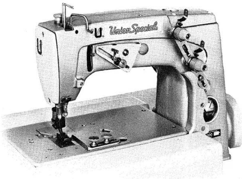
Black-and-white photo of a Union Special sewing machine (no visible text or symbols on the device body)Series 50000 - Machines
with "Air-Klipp®" Chain Cutter

natural_image
Pure diagram of a U-shaped pipe or tube with no text, numbers, or symbolsFinest Quality
Union Special®
Industrial Sewing Equipment
CATALOG NO. T129VF (SUPPLEMENT TO CATALOG NO. 129M)
ADJUSTING INSTRUCTIONS AND
ILLUSTRATED PARTS LIST FOR
SERIES 50000
MACHINES WITH AIR-KLIPP®
VACUUM TYPE CHAIN CUTTER
STYLES
56300 VF
56300 VG
Second Edition
©1977, 1982
By
Union Special Corporation
Rights Reserved in All Countries
Printed in U.S.A.
June, 1982
IDENTIFICATION OF MACHINES
Each UNION SPECIAL machine is identified by a Style number on a name plate on the machine. Style numbers are classified as standard and special. Standard Style numbers have one or more letters suffixed, but never contain the letter "Z".Example: "Style 56300 VF". Special Style numbers contain the letter "Z". When only minor changes are made in a standard machine, a "Z" is suffixed to the standard Style number. Example: "Style 56300 VFZ".
Styles of machines similar in construction are grouped under a class number which differs from the style number, in that it contains no letters. Example: "Class 56300".
APPLICATION OF CATALOG
This catalog is a supplement to Catalog No. 129 M, Fifth Edition, and should be used in conjunction therewith. Only those parts which are used on Styles 56300 VF and 56300 VG, but not used on Styles 56300 F or 56300 G are illustrated and listed at the back of this book. For clarity, certain 56300 F and 56300 G parts are shown in phantom to assist in locating the 56300 VF and 56300 VG parts. Opposite the illustration pages, parts are identified by a reference number, part number, description and amount required. Any part that is a component of another part is indicated by indenting its description under the description of the assembly or base part. Always use the part number in the second column, never use the reference number in the first column when ordering repair parts.
This catalog applies specifically to the Standard Styles of machines as listed herein. It can also be applied with discretion to some Special Styles of machines in this class. References to direction, such as right, left, front, back, etc., are given from the operator's position while seated at the machine. Operating direction of handwheel is toward the operator.
STYLES OF MACHINES IN CLASS 56300
Advanced High Speed Single Needle Flat Bed Machines, Medium Throw, Needle Bearing Needle Bar Drive, Light Weight Presser Bar and Needle Bar Driving Mechanism, Single Reservoir Enclosed Positive Automatic Lubricating System, Filtered Oil Return Pumps for Head and Base, Lateral Looper Travel, Large Handwheel and Improved Belt Guard, Indexed Thread Ratio Control Parts, "Air-Klipp" Vacuum Chain Cutter, prepared for use with Knee Press for Presser Foot Lifter, Equipped with Disc Thread Tensions, Maximum Work Space to Right of Needle Bar 8 1/4 Inches (209.6 mm).
56300 VF Equipped with thumbscrew adjustable frame needle thread eyelet and feeding presser foot, for seaming operations such as attaching pocket facings, run-stitching pocket and cuff flaps and similar operations on koratron or permanent press materials. Seam Spec. 401-SSa-1. Type 128 GBS needle. Maximum recommended speed 6500 R.P.M.
56300 VG Equipped with thumbscrew adjustable needle thread frame eyelet, for seaming trousers, coats and for similar operations on precured perma-press material. Seam Spec. 401-SSa-1. Type 128 GBS needle. Maximum recommended speed 6500 R.P.M.
NEEDLES
Each needle has both a type and size number. The type number denotes the kind of shank, point, length, groove, finish and other details. The size number, stamped on the needle shank, denotes the largest diameter of blade, measured midway between shank and eye. Collectively, type and size number represent the complete symbol, which is given on the label of all needles packaged and sold by Union Special.
Standard recommended needle for Styles 56300 VF and 56300 VG is Type 128 GBS. It has a round shank, round point, short, double groove, struck groove, ball eye, spotted, ball point, chromium plated and is available in sizes 080/032,090/036, 100/040, 110/044, 125/049, 140/054, 060.
To have needle orders promptly and accurately filled, an empty package, a sample needle, or the type and size number should be forwarded. Use description on label. A complete order would read: "1000 Needles, Type 128 GBS, Size 080/032".
Selection of the proper needle size should be determined by size of thread used. Thread should pass freely through needle eye in order to produce a good stitch formation.
USE GENUINE REPAIR PARTS
Success in the operation of these machines can be secured only with genuine UNION SPECIAL repair parts as furnished by the Union Special Corporation, its subsidiaries and authorized distributors. They are designed according to the most approved scientific principles, and are made with utmost precision. Maximum efficiency and durability are assured.
IDENTIFYING PARTS
Where the construction permits, each part is stamped with its part number. On some of the smaller parts and on those where construction does not permit, an identification letter is stamped in to distinguish the part from similar ones.
Part numbers represent the same part, regardless of catalog in which they appear.
IMPORTANT! ON ALL ORDERS, PLEASE INCLUDE PART NAME AND STYLE OF MACHINE FOR WHICH PART IS ORDERED.
TERMS
Prices are strictly net cash and subject to change without notice. All shipments are forwarded f.o.b. shipping point. Parcel Post shipments are insured unless otherwise directed. A charge is made to cover postage and insurance.

text_image
FILL MAIN RESERVOIR HERE FOR CORRECT OIL LEVEL NEEDLE OF GAUGE SHOULD BE IN OPERATE POSITION CAUTION! FILL ALL OIL RESERVOIRS BEFORE STARTING. MACHINE HAS BEEN DRAINED BEFORE SHIPPING.Fig. 1
THREADING AND OILING DIAGRAM FOR STYLES 56300 VF and VG.
The oil has been drained from the machine before shipping and the reservoir must be filled before starting to operate. Maintain oil level in "OPERATE" position and add oil when needle is to the black line located to the left of the "OPERATE" zone marked "LOW". The machine is automatically lubricated and no oiling other than keeping the main reservoir filled is necessary. For further lubricating instructions refer to paragraph on "LUBRICATION" and "RECOMMENDED OIL".
Thread machine Styles 56300 VF and VG in accordance with the above threading diagram.
LUBRICATION
Use a straight mineral oil with a Saybolt viscosity of 90 to 125 seconds at 100 degrees F. This is equivalent to Union Special Corporation Specification No. 175.
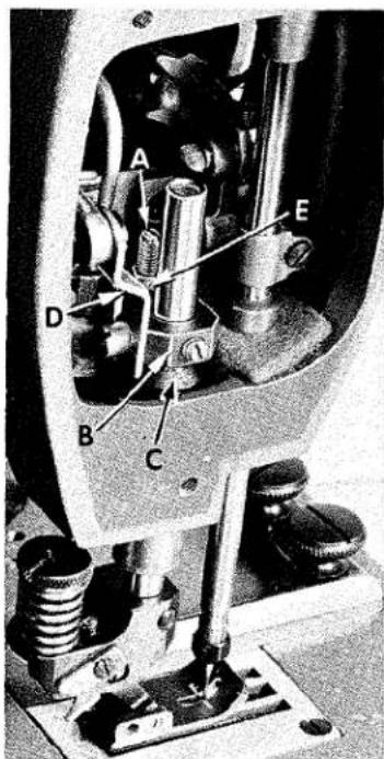
Before operating, fill machine with oil at plug screw (A, Fig. 2). While filling machine with oil, check gauge (B). When proper oil level is reached, gauge needle will register on black line marked "FULL". Oil must be added when gauge needle registers on black line marked "LOW". Although the machine can be operated safely when gauge needle registers in the "OPERATE" zone, it is recommended to always check oil level before operating, to be sure machine is filled with oil to the "FULL" mark. CAUTION: DO NOT over fill machine.
To drain oil, remove plug screw (C), or lower crank chamber cover on back of machine. Oil must be changed every 2000 operating hours to minimize wear.
On new machines, or a machine out of service for an extended period of time; lubricate machine as follows:
Remove head cover, clean out lint, then directly oil needle bar link and needle bar. Replace head cover and fill machine with oil to proper level. Run machine at low RPM to ensure proper lubrication of components preventing any damage which may occur from lack of oil distribution.

text_image
acial A G B 56300 E DFig. 2
ADJUSTING INSTRUCTIONS
OIL GAUGE CALIBRATION
To recalibrate oil gauge, follow instructions in sequence as listed:
- Place machine upright on a level surface.
- Remove plug screw (C, Fig. 2) and tip machine forward to drain all oil from reservoir.
- Remove lower crank chamber cover on back of machine.
- Fill reservoir until oil is even with bottom of knee press shaft bushing (D).
- Loosen locknut (E) and rotate calibrating screw (F) as required until gauge needle registers on the black line marked "LOW".
- Tighten locknut (E), then replace plug screw (C) and lower crank chamber cover.
- Fill machine with oil until gauge needle registers on black line marked "FULL".
text_image
Technical diagram of a mechanical assembly with labeled parts A through FFig. 3
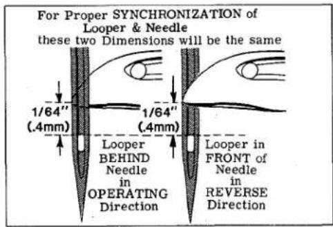
Insert looper into the looper rocker, pushing it all the way down and tighten screw against flat on shank of looper. Turn handwheel in operating direction until the point of the looper (A, Fig. 3) moving to the left, is even with the left side of needle (B). Note the height of the eye of the needle with respect to the looper point (See Fig. 4). Turn the handwheel in the reverse direction until the point of looper again moving to the left, is even with the left side of needle (See Fig. 4). If the height of the eye of the needle with respect to the looper point are the same, looper and needle motions are synchronized - a variation of .005 inch (.127mm) is allowable. If the distance from the eye of the needle to the point of the looper is greater when the handwheel is turned in the operating direction, the looper drive lever rocker shaft will have to be moved slightly towards the rear. Moving the shaft towards the front acts the reverse.
text_image
For Proper SYNCHRONIZATION of Looper & Needle these two Dimensions will be the same 1/64" (.4mm) 1/64" (.4mm) Looper BEHIND Needle in OPERATING Direction Looper in FRONT of Needle in REVERSE DirectionFig. 4
NOTE: The 1/64 inch (.4mm) dimension shown in Fig. 4 is for final setting of needle bar height. Adjust looper drive rocker lever shaft as follows:
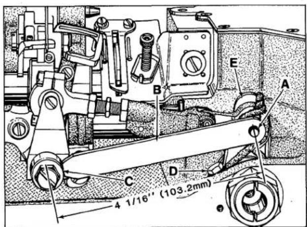
Loosen screw (C, Fig. 3) in looper drive lever (D). A rod of .146-40 thd. or Union Special Screw No. 22870 A can be threaded into the looper drive lever rocker shaft through the center of thrust adjusting screw (E). Tap or pull slightly as required to position shaft for proper synchronization. Tighten screw (C) securely and remove rod or screw used to position shaft. Loosen lock nut (F) and TORQUE thrust adjusting screw (E) to 6 in. lbs. (7cm/kg); re-tighten lock nut (F) securely.
text_image
4 1/16" (103.2mm) A B C D EFig. 5
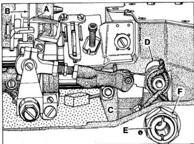
With looper at extreme right end of its travel, check location of the centerline of right looper connecting rod bearing using gauge No. 21227 CX. Remove nut from looper lever stud (A, Fig. 5) and place hole in gauge (B) over threaded stud. The left end of gauge should locate against the RIGHT side of looper rocker cone (C). If adjustment is necessary, loosen clamp screw (D), reposition looper drive lever (E) as required and retighten screw (D). If gauge is not available, setting can be checked with a scale. Dimension from centerline of stud (A) to centerline of cone (C) which should be 4 1/16 inch (103.3mm).
Insert a new needle, type and size as specified. Looper gauge is 5/32 inch (3.97mm) for Styles 56300 VF and 56300 VG. Set the looper (A, Fig. 6) so the distance from the center of the needle (B) to the point of the looper (A) is 5/32 inch (3.97mm), when the looper is at its farthest position to the right. Looper gauge No. 21225-5/32 (C, Fig. 5) can be used advantageously in making this adjustment. If adjustment is required, loosen nut (D) (it has a left hand thread) and nut (E) on connecting rod (F), turn the connecting rod forward or backward to obtain the 5/32 inch (3.97mm) dimension. Re-tighten both nuts, first nut (E), then nut (D). Make sure the left ball joint is in vertical position and does not bind after adjustment.

text_image
(3.97 mm) 32 A B C D H F E GFig. 6

text_image
A BFig. 7
The looper is set correctly in line-of-feed, if, as it moves to the left, behind the needle, its point (A, Fig. 7) brushes, but does not pick at the rear of needle (B).
If adjustment is necessary, loosen lock screw (G, Fig. 6) and turn stop screw (H) as required. Turning stop screw clockwise sets the looper to the rear and turning it counterclockwise acts the reverse. Holding looper to the front while making this adjustment may prove helpful. Tighten lock screw when setting is obtained and recheck the adjustment.
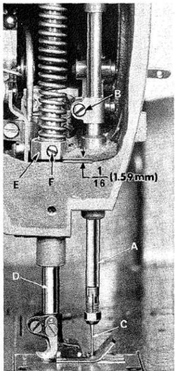
SETTING HEIGHT OF NEEDLE BAR
The height of the needle (C, Fig. 8) is correct when the top of its eye is 1/64 inch (.4mm) below the underside of the looper, with the looper point flush with the left side of the needle (See Fig. 4). If adjustment is necessary, loosen screw (B, Fig. 8) and move needle bar (A) up or down as required and retighten screw.
text_image
E F B 1/16 (1.59 mm) A D CFig. 8
The needle must have equal clearance on the right and left sides of the needle slot in throat plate. The descending needle must be deflected on the back of the looper.
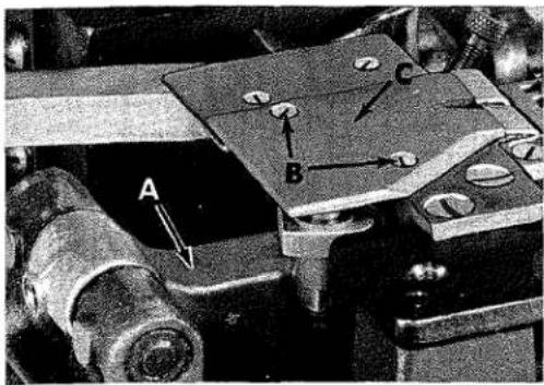
SETTING THE FEED DOG
Set the feed dog (A, Fig. 9) in the throat plate (B) so there is equal clearance on all sides. See that the tips of the teeth extend the depth of a tooth or approx-

text_image
B C A D 3" 64 (1.19mm)Fig. 9
imately 3/64 inch (1.19 mm) above the throat plate and are parallel with the throat plate at high point of travel. Adjust the support screw (C), under the feed dog, to maintain this setting. Screw (D) is used to hold feed dog in position.
If feed dog teeth are not parallel with the throat plate, loosen nut (A, Fig. 10) and turn screw (B) clockwise to lower the front teeth, or counterclockwise to raise the front teeth. Retighten nut when feed dog is set properly.

text_image
Technical diagram of a mechanical assembly with labeled components A through GFig. 10
Should it be necessary to move the feed dog to the left or right, loosen screws (A, Fig. 11) which hold the feed rocker (B) onto the feed rocker shaft (C), and move feed rocker to desired position and retighten screws. Make sure the feed rocker arm (D) does not bind after making this adjustment.
When handwheel is turned in operating direction the feed dog should have equal clearance on both ends of the throat plate slots with feed travel set to desired stitch length.
Should it be necessary to move the feed dog forward or backward, loosen nut (E, Fig. 11) which clamps the feed rocker arm to the feed rocker and move the feed rocker forward or backward as needed and retighten nut.
CHANGING STITCH LENGTH
Set the stitch to required length. This is accomplished by loosening locknut (F, Fig. 11) 1/2 turn (it has a left hand thread) on the end of the stitch regulating

text_image
L G H F L J K E C V A B DFig. 11
stud and turning the stitch adjusting screw (G) located under the left end of the cloth plate, in the head of main shaft (H), which is marked with "L" and "S". Turning the screw clockwise shortens the stitch (moves stitch regulating stud toward the "S") and turning it in a counterclockwise direction lengthens the stitch (moves stitch regulating stud toward the "L"). Retighten locknut securely. To prevent destructive damage to the feed drive bearing, Key screw (J) must engage the "U" shaped key slot in ferrule (K).
NOTE: Any change in stitch length will necessitate a corresponding change in rear needle guard setting.
CHANGING STITCH LENGTH (Continued)
Machines having needle bearings in the feed rocker at locations (L, Fig. 11) may require repacking after years of service. Bearings should be thoroughly cleaned and repacked with Union Special Corporation grease No. 28604 P.
SETTING REAR NEEDLE GUARD
Set rear needle guard (C, Fig. 10) horizontally so that it does not quite contact the rear of needle (D) when at its most forward point of travel. A clearance of .005 inch (.127mm) is permissible. It should be set as low as possible, yet have its vertical face approach within about 3/64 inch (1.19mm) of the needle, until the point of looper (E), moving to the left, is even with the needle. To move needle guard forward or backward, loosen screw (F), move needle guard as required, and retighten screw. To raise or lower needle guard, loosen screw (F), and turn screw (G) clockwise to lower needle guard or counterclockwise to raise it. Retighten screw (F) after guard is properly set.
NOTE: Any change in stitch length will require a change in rear needle guard setting.
THREAD TENSIONS
Tension on the needle thread should be only sufficient to produce uniform stitches on the under surface of the fabric.
Pull needle thread through the eyelets and set the needle thread tension at 3 ounces (85.05 gr).
Looper thread tension is applied at the cast-off support tension disc assembly, and the adjusting nut should be set so that the tension on looper thread is just sufficient to steady the thread.
THREAD TENSION RELEASE
Thread tension release is set correctly when it begins to function as the presser foot is raised to within 1/8 inch (3.17mm) of the end of its travel and is entirely released when the presser foot has reached its highest position.
text_image
A BFig. 12

text_image
B E F 1/16 (1.59mm) A D CFig. 13
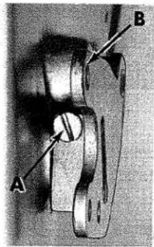
If adjustment is needed, loosen tension release lever screw (A, Fig. 12), located at the back of the machine and move tension disc separator as required. Retighten screw. After adjustment there should be no binding at any point.
Height of presser bar (D, Fig. 13) is set correctly if it is possible to remove the presser foot when foot lifter lever (B, Fig. 12) is fully depressed.
PRESSER BAR HEIGHT (FOR 56300 VG Continued)
Also there should be approximately 1/16 inch (1.59mm) clearance between lower surface of the presser bar connection and guide (E, Fig. 13) and the bottom surface of the head opening in the bed when foot lifter lever is released and the presser foot resting on the throat plate, with feed dog down below the throat plate.
text_image
A B 3/4 (19.05mm) 1 7/16" (36.51mm) UnionSpecial C DFig. 14
If adjustment is needed, turn handwheel in operating direction until needle bar is in the low position. Loosen screw (F, Fig. 13). While holding presser foot down on the throat plate surface, pry up presser bar connection guide with a screwdriver to obtain the 1/16 inch (1.59mm) setting and tighten screw (F). Check setting by turning handwheel so that needle bar is in its high position and see if presser foot can be removed as mentioned in previous paragraph.
PRESSER FOOT PRESSURE (FOR 56300 VG)
Adjust presser spring regulating screw (A, Fig. 14) so that it exerts only enough pressure on the presser foot to feed the work uniformly when a slight tension is placed on the fabric. This is the knurled screw, located directly behind the needle bar in the head of the machine. Turning it
clockwise increases the pressure, counterclockwise acts the reverse.
THREADING
Refer to threading diagram (Fig. 1) for the manner in which these machines are threaded.
SETTING NEEDLE THREAD TAKE-UP WIRE AND FRAME EYELET
These machine styles are equipped with thread handling and control parts, so the adjusting sequence should be made in the following manner:
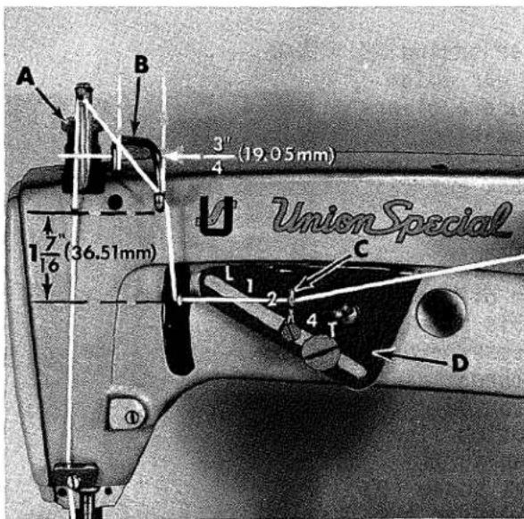
With needle bar at the top of its stroke, set needle thread take-up wire (B, Fig. 14) so its lower extended surface is 1 7/16 inch (36.51mm) above centerline of needle lever thread eyelet hole and 3/4 inch (19.05mm) across the centerlines of its vertical surfaces(See Fig. 14).
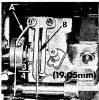
Set looper thread guide eyelet (A, Fig. 15) so its left outer surface is 3/4 inch (19.05mm) from the left side of looper thread take-up (B), (See Fig. 15).
text_image
A B 3 4 (19.05mm)Fig. 15
Adjust looper thread tension to a minimum required for controlling the looper thread (light). Set thread index eyelet (C, Fig. 14) at "3" on the adjusting plate (D). Changing the needle thread tension only, balance the stitch so that when 6" of sewn seam are raveled back, the needle thread is approximately as long as the looper thread. A 1" difference in lengths is permissible.
SETTING NEEDLE THREAD TAKE-UP WIRE AND FRAME EYELET (Continued)
NOTE: Use a sample of material to be sewn. Maintaining this needle thread tension, move thread index eyelet (C) up toward "L" to obtain a looser seam (longer needle loops) and toward "T" to obtain a tighter seam.
FEEDING PRESSER FOOT (56300 VF ONLY)
Remove presser spring regulator and presser spring. Adjust long stop screw (A, Fig. 16) in presser bar guide (B) against the bed casting as required to ensure a clearance between the guide and top of presser bar bushing (C), yet so the guide is pulled up quickly by lifter lever link (D) when foot treadle is activated. Tighten lock nut (E) on stop screw.
As a preliminary setting, adjust spring regulator nut (A, Fig. 17) on the feeding presser foot so the distance from the top of the spring (B) to the yoke (C) is 5/8 inch (15.88mm), (See Fig. 17). Assemble feeding presser foot to presser bar. With presser foot resting on throat plate and feed dog down, press down on spring regulator nut (A, Fig. 17) until the marks on presser foot bottom line up with the centerline of the needle, while keeping the needle in the center of needle slot, tighten set screw (D) securing presser bar guide to the presser bar, making sure that the stop screw in presser bar guide is resting on the bed casting.
Replace presser spring and presser spring regulator. Turn presser bar spring regulator screw down until the threaded portion is level with the head casting.
text_image
Technical diagram of a mechanical device with labeled parts A, B, C, D, E and directional arrows indicating movement or assembly.Fig. 16
Note: Any change in the alignment of needle in rela- fionship to the marks on the presser foot bottom probably means that the stop screw of the presser bar guide was not seated against bed cast- ing before locking set screw.
When the presser foot is lifted off the bare throat plate, the foot should move back only slightly, less than 1/64 inch (.40mm). The stop screw (E, Fig. 17) on the yoke, which is set at the factory, can be readjusted if necessary, should this dimension become changed.
CHECK
Presser foot at back of needle slot should cover most of throat plate land when resting on the bare throat plate.
When the presser foot bottom is raised by material so that the feeding foot spring bottoms, the back of the needle slot should clear the needle. The main presser bar should not lift before the feeding foot spring bottoms.

text_image
5/8 (15.88 mm) A B C D EFig. 17
CHECK (Continued)
The purpose of the feeding foot is to make the top and bottom ply of cloth feed the same amount without pulling on the bottom ply. The 5/8 inch (15.88mm) setting on the feeding foot spring usually gives a good matching of piles and a strong feeding pull. Reducing this pressure will tend to feed the top ply more. Increasing this pressure will tend to feed the bottom ply more.
ADJUSTING LOWER KNIFE ON "AIR-KLIPP" CHAIN CUTTER
text_image
Technical diagram of a mechanical assembly with labeled components A, B, and CFig. 18
Cutting edge of the lower knife should overlap the thread opening by 1/64 inch (.40mm) to cut properly. The back edge of the knife should not enter the thread opening forming a triangle where the thread chain could get caught. The lower life is driven by the feed bar (A, Fig.18).
To adjust lower knife; (1) remove screws (B, Fig. 18).
CAUTION! When removing screws (B) the lower knife is being held against the bottom of the upper knife (C) by spring (A, Fig. 19) and will come out of place when upper knife is removed.
(2) Loosen screw (B, Fig. 19) and move lower knife holder (C, Fig. 19) forwards or backwards for correct knife travel, with the knife at its farthest travel to the right.

text_image
A B CFig. 19
SPECIAL INSTRUCTIONS
NEEDLE LEVER
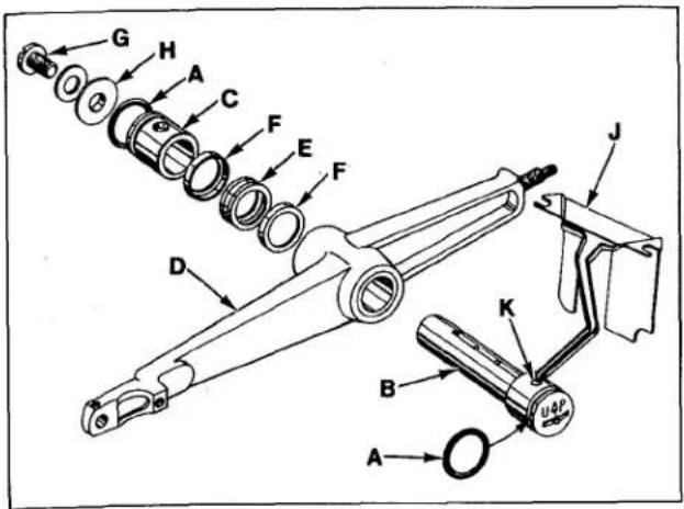
When adjusting needle lever or replacing related parts, follow instructions in sequence as listed:
- Install "0" rings (A, Fig. 20) onto needle lever stud (B) and thrust collar (C).
- With needle lever (D) in machine and positioned properly; insert stud (B) through hole in needle lever until its shoulder contacts the needle lever and the word
"UP" on stud is in the upright position. While making sure no binding exists in the needle bar link, secure stud (B) with the front set screw in top of machine bed.
text_image
Technical diagram of a mechanical assembly with labeled parts A through J, showing exploded and assembled views.Fig. 20
- Install temper load ring (E) and compression cups (F) onto stud (B), then push ring and cups through opening in machine bed.
NEEDLE LEVER (Continued)
-
Install thrust collar (C) onto stud (B) being careful not to damage "O" ring. Compress components together by tightening screw (G) until washer (H) bottoms against stud (B). Secure stud (B) in position using the rear set screw in top of bed.
-
To check temper load ring for proper compression, remove screw (G) from stud (B) and loosen rear set screw in top of bed. Thrust collar (C) should spring out .003 - .007 inch (.08 - .18mm). Compress load ring in reverse order, then tighten rear set screw.
-
With indented "UP" on stud (B) in upright position, install bearing oiler (J) so its hook sets in oil supply hole (K) of stud. When hook and stud are secured in their proper positions, the proper amount of oil will be channeled to stud for lubricating needle lever (D).
text_image
C A A C 1/32" (8mm) D F B F EFig. 21
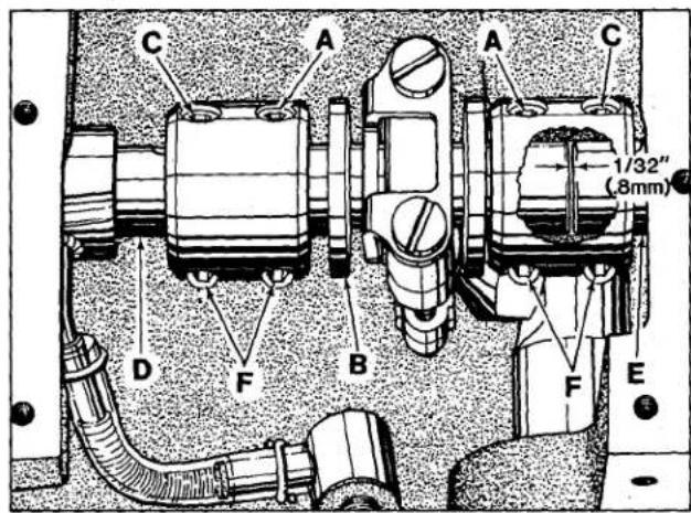
ALIGNING MAINSHAFT TO CRANKSHAFT
As viewed looking down from rear of machine, spot screws (A, Fig. 21) in the couplings must align with the spots in the looper drive crank (B) and set screws (C) must align with the flats on crankshaft (D) and mainshaft (E). Mainshaft must be positioned laterally with .045 inch (1.14mm) clearance between the right side of its head and the bed casting as shown in Fig. 22.
Looper drive crank (B, Fig. 21) must be positioned laterally with 1/32 inch (.8mm) clearance between it and mainshaft (E) as shown in Fig. 21. Once these settings are made, it is very important that the couplings are tightened in the following sequence for best performance.
Tighten spot screws (A) temporarily, to the looper drive crank. Tighten set screws (C) temporarily, to the crankshaft and mainshaft. Torque screws (F) to 19-21 in. lbs. (22-24cm/kg). Loosen spot screws (A) and set screws (C). Re-torque screws (F) to 19-21 in. lbs. (22-24cm/kg), then, torque screws (A and C to 19-21 in. lbs. (22-24cm/kg).

text_image
.045" (1.14mm)Fig. 22
ALIGNING MAINSHAFT TO CRANKSHAFT (Continued)
The oil drip plate (A, Fig. 23) located in the oil reservoir should be positioned with its tip in the recessed cut out in the bed casting, as far to the left as possible without touching. It has elongated mounting holes and can be adjusted by loosening (2) screws (B) in top of the oil reservoir back cover to position as required, retighten screws.

text_image
A BFig. 23
text_image
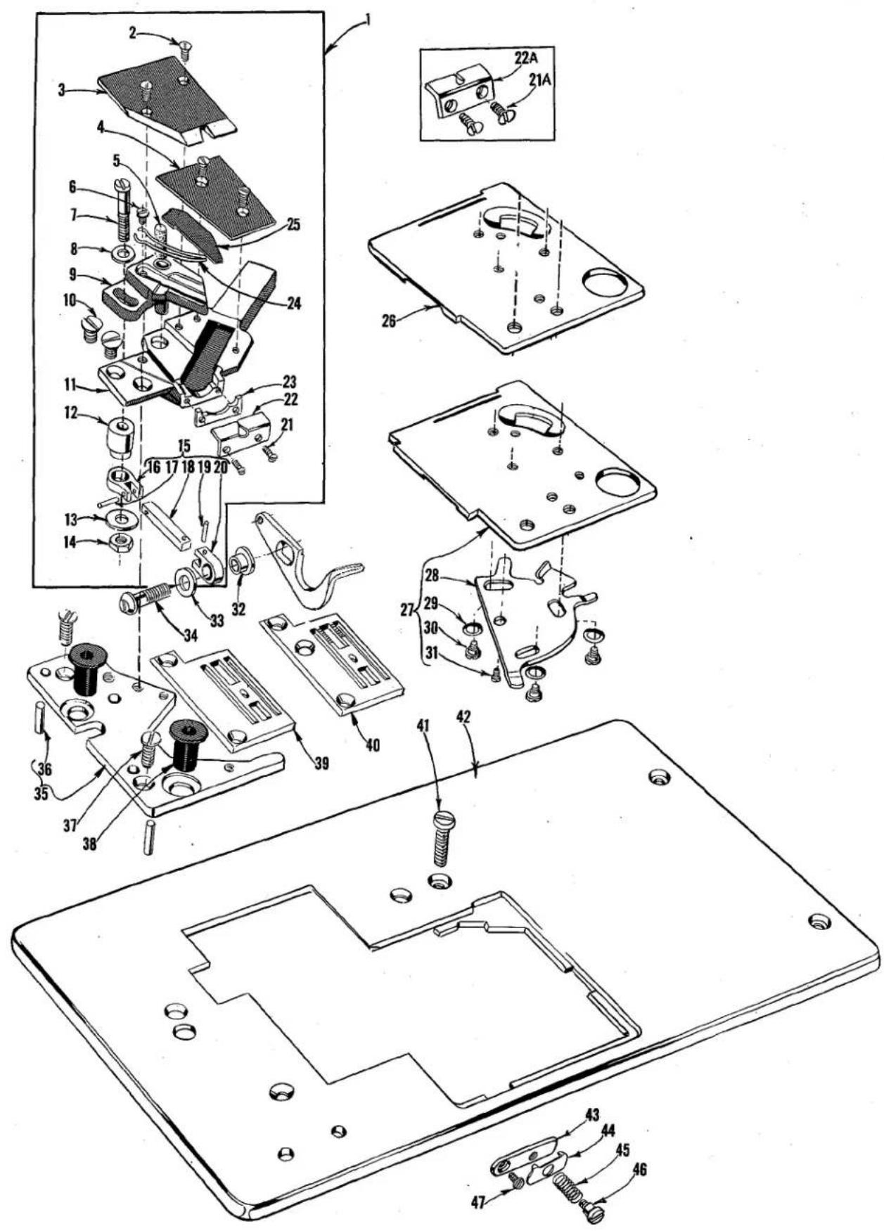
Exploded view diagram of a device with numbered parts and exploded views, including labeled components like 21A, 22A, and 47.The parts illustrated on pages 14 and 16, and described on this page and page 17 represent the parts that are used on Styles 56300 VF and VG, but not used on Styles 56300 F and G.
Unless otherwise specified in the description, the parts are used on all the machine styles covered in this catalog. The parts shown in phantom views and bearing no reference numbers are common to Styles 56300 F, G, VF and VG.
Use Catalog No. 129 M Fifth Edition Style 56300 F for 56300 VF, and Style 56300 G for 56300 VG, for all parts not illustrated or described in this catalog.
Reference numbers that are inside a bracket or box on the picture plate and have indented descriptions, indicate they are component parts of a complete part or assembly.
"AIR-KLIPP" CHAIN CUTTER, THROAT PLATE, CLOTH PLATE, CLOTH PLATE COVER AND MISCELLANEOUS PARTS
| Ref.No. | PartNo. | Description | Amt.Req. |
| # 1 | G29914 | Air-Klipp, for Style 56300 VG | 1 |
| * - | G29914 A | Air-Klipp, for Style 56300 VF | 1 |
| 2 | 77 K | Screw | 4 |
| *# 3 | 99670 F | Upper Knife | 1 |
| 4 | 99584 C | Air-Klipp Cover | 1 |
| 5 | 999-170 | Oil Felt- | 1 |
| 6 | HT2C | Screw | 1 |
| 7 | 22729 B | Screw | 1 |
| 8 | 80265 | Washer- | 1 |
| 9 | 99671 C | Knife Holder, marked "MF" | 1 |
| 10 | 22807 | Screw | 2 |
| 11 | 99691 | Air-Klipp Frame | 1 |
| 12 | 99673 E | Bushing | 1 |
| 13 | 51225 W | Washer- | 1 |
| 14 | 41071 G | Nut | 1 |
| 15 | 99672 H | Knife Driving Link Assembly | 1 |
| 16 | 99672 R | Knife Driving Link- | 1 |
| 17 | 96516 | Pin | 1 |
| 18 | 99672 J | Connecting Rod- | 1 |
| 19 | 96515 | Pin | 1 |
| 20 | 99672 R | Knife Driving Link- | 1 |
| 21 | 99316 | Screw, for No. G29914 | 2 |
| 21A | 22716 A | Screw, for No. G29914 A | 2 |
| 22 | 99677 J | Inlet, marked "GJ", for No. G29914- | 1 |
| 22A | 99677 L | Inlet, marked "GL", for No. G29914 A- | 1 |
| 23 | 99659 B | Spacer, for No. G29914- | 1 |
| 24 | 99697 | Spring- | 1 |
| *#25 | 99669 D | Lower Knife, marked "GJ"- | 1 |
| 26 | 56381-212 | Cloth Plate Cover, for Style 56300 VF | 1 |
| #27 | G56381-222 | Cloth Plate Cover, for Style 56300 VG | 1 |
| 28 | 51281 AC | Cloth Plate Cover Spring- | 1 |
| 29 | 35772 H | Spring Washer | 3 |
| 30 | 22760 A | Screw | 3 |
| 31 | 22845 B | Screw | 1 |
| *#32 | 99673 D | Link Bushing- | 1 |
| *#33 | 99652 A | Washer- | 1 |
| *#34 | 99331 | Cylinder Screw- | 1 |
| *#35 | G56380 | Throat Plate Support- | 1 |
| 36 | 51280 J | Dowel Pin | 2 |
| 37 | 80 | Screw, for throat plate support | 2 |
| 38 | 660-313 | Well Nut- | 2 |
| #39 | GA51324 | Throat Plate, for Style 56300 VG- | 1 |
| *40 | GA51324 W | Throat Plate, for Style 56300 VF- | 1 |
| 41 | 22839 E | Screw, for cloth plate- | 1 |
| 42 | 56301 D | Cloth Plate | 1 |
| 43 | 43296 | Nipper Spring Base- | 1 |
| 44 | 57 WB | Nipper Spring Plate | 1 |
| 45 | 15438 C | Nipper Spring | 1 |
| 46 | 57 WD | Nipper Spring Screw | 1 |
| 47 | 605 A | Screw, for nipper spring base | 1 |
* May be ordered complete as No. 29480 MV for Style 56300 VF.
May be ordered complete as No. 29480 MW for Style 56300 VG.
text_image
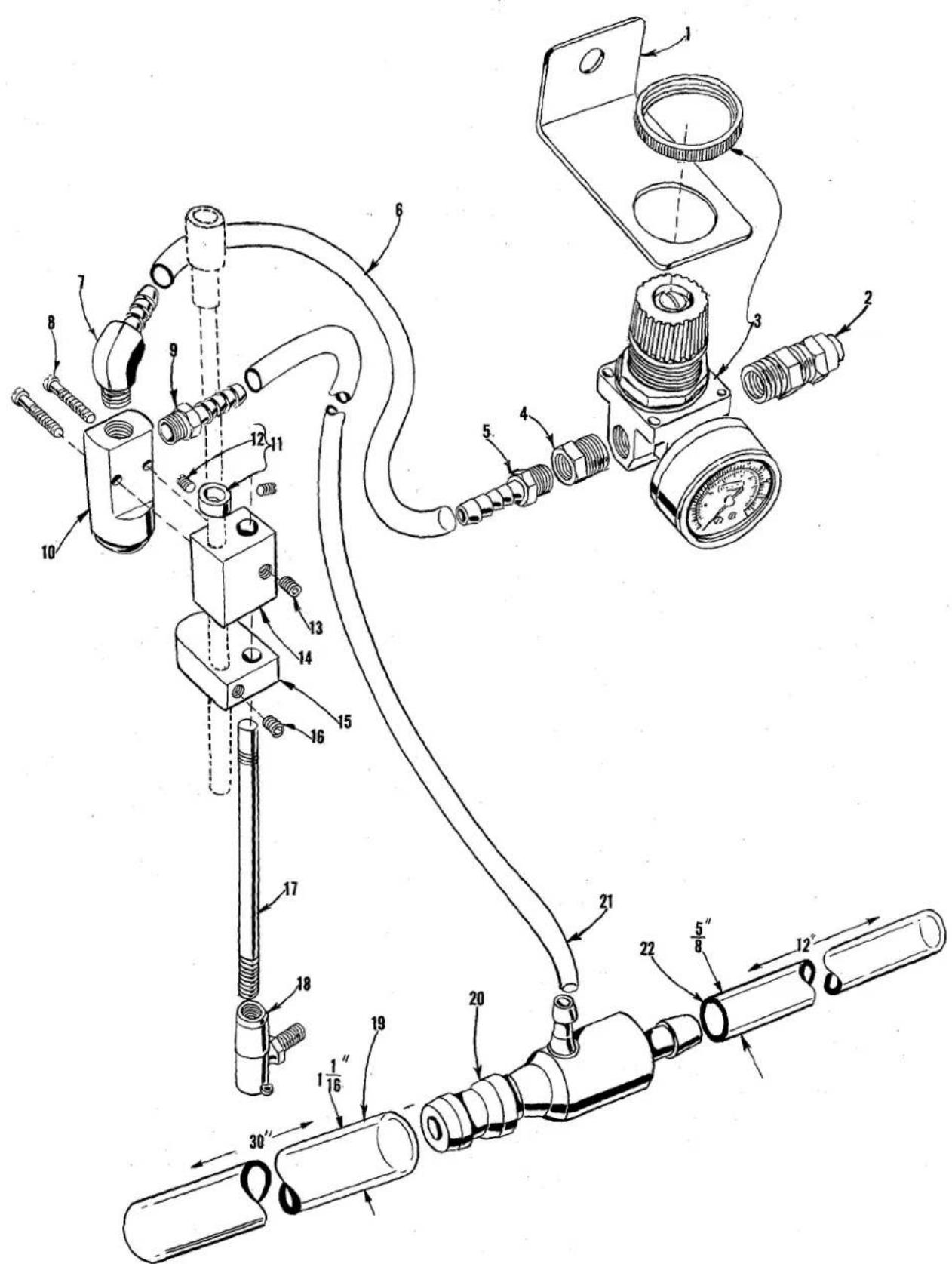
Technical diagram of a mechanical assembly with numbered components and labeled partsPNEUMATIC PARTS
| Ref.No. | PartNo. | Description | Amt.Req. |
| 1 | 39583 A | Mounting Bracket - - - - - - - - - - - - - - - - - - - - - - - - - - - - - - - - - - - - - - - - - - - - - - - - - - - - - - - - - - - - - - - - - - - - - - - - - - - - - - - - - - - - - - - - - - - - - - - - - - - - | 1 |
| 2 | 671 F-8 | Straight Fitting - - - - - - - - - - - - - - - - - - - - - - - - - - - - - - - - - - - - - - - - - - - - - - - - - - - - - - - - - - - - - - - - - - - - - - - - - - - - - - - - - - - - - - - - - - - - - - - - - - - | |
| 3 | 671 D-7 | Pressure Regulator and Gauge - - - - - - - - - - - - - - - - - - - - - - - - - - - - - - - - - - - - - - - - - - - - - - - - - - - - - - - - - - - - - - - - - - - - - - - - - - - - - - - - - - - - - - - - - - - - - - - - - - - | |
| 4 | 671 F-6 | Reducer Bushing- - - - - - - - - - - - - - - - - - - - - - - - - - - - - - - - - - - - - - - - - - - - - - - - - - - - - - - - - - - - - - - - - - - - - - - - - - - - - - - - - - - - - - - - - - - - - - - - - - - - 1 | |
| 5 | 671 F-1 | Male Fitting - - - - - - - - - - - - - - - - - - - - - - - - - - - - - - - - - - - - - - - - - - - - - - - - - - - - - - - - - - - - - - - - - - - - - - - - - - - - - - - - - - - - - - - - - - - - - - - - - 1 | |
| 6 | 671 B-1 | Air Tube, 36 inches (914.4mm) long - - - - - - - - - - - - - - - - - - - - - - - - - - - - - - - - - - - - - - - - - - - - - - - - - - - - - - - - - - - - - - - - - - - - - - - - - - - - - - 1 | |
| 7 | 671 F-2 | Elbow Fitting- - - - - - - - - - - - - - - - - - - - - - - - - - - - - - - - - - - - - - - - - - - - - - - - - - - - - - - - - - - - - - - - - - - - - - - - - - - - - - - - - - - - 1 | |
| 8 | 22729 B | Screw- - - - - - - - - - - - - - - - - - - - - - - - - - - - - - - - - - - - - - - - - - - - - - - - - - - - - - - - - - - - - - - - - - - - - - - - - - - - - - - - 2 | |
| 9 | 671 F-1 | Male Fitting - - - - - - - - - - - - - - - - - - - - - - - - - - - - - - - - - - - - - - - - - - - - - - - - - - - - - - - - - - - - - - - 1 | |
| 10 | 671-1 | Air Valve- - - - - - - - - - - - - - - - - - - - - - - - - - - - - - - - - - - - - - - - - - - - - - - - - - - 1 | |
| 11 | 61242 | Pitman Rod Collar- - - - - - - - - - - - - - - - - - - - - - - - - - - - - - - - - - - - - - - - - - - - - - - 1 | |
| 12 | 88 | Screw- - - - - - - - - - - - - - - - - - - - - - - - - - - - - - - - - - - - - - - - - 2 | |
| 13 | 22651 CB-4 | Set Screw- - - - - - - - - - - - - - - - - - - - - - - - - - - - - - - - - - - 1 | |
| 14 | 671-2 | Air Valve Mounting Block - - - - - - - - - - - - - - - - - - - - - 1 | |
| 15 | 671-3 | Air Valve Actuator Block - - - - - - - - - - - - - - - - - - - - 1 | |
| 16 | 22651 CB-4 | Set Screw- - - - - - - - - - - - - - - - - - - - - - - - - 1 | |
| 17 | 1453 A | Pitman Rod | 1 |
| 18 | 21371 MZ | Connection - - - - - - - - - - - - - - - - - - - - - - 1 | |
| 19 | 671 B-11 | Air Tube, 30 inches (762.0mm) long - - - - - - - - - 1 | |
| 20 | 671 D-2 | Air Jet- - - - - - - - - - - - - - - - 1 | |
| 21 | 671 B-3 | Air Tube, 45 inches (1143.0mm) long- - - - - - - - 1 | |
| 22 | 671 B-12 | Air Tube, 12 inches (304.8mm) long- - - - - - - 1 | |

natural_image
World map of the Americas and surrounding oceans and equatorial regions, showing continents and latitude/longitude lines (no text labels)WORLDWIDE SALES AND SERVICE
Union Special Corporation maintains sales and service facilities throughout the world. These offices will aid you in the selection of the right sewing equipment for your particular operation. Union Special Corporation representatives and servicemen are factory trained and are able to serve your needs promptly and efficiently. Whatever your location, there is a Union Special Corporation representative to serve you. Check with him today.
It is important to remember that LEWIS® and COLUMBIA® machines are also products of Union Special Corporation, thus offering the industry the most complete line of the Finest Quality sewing machines.
Norcross, GA
Chicago, IL
Dallas, TX
Commerce, CA
New York, NY
Philadelphia, PA
Woburn, MA
Opa-Locka, FL
Montreal, Quebec
Toronto, Ontario
Catano, Puerto Rico
Brussels, Belgium
Leicester, England
Paris, France
Stuttgart, W. Germany
Hong Kong
Other Representatives throughout
all parts of the world

text_image
UnionSpecial® Finest Quality Industrial Sewing EquipmentUnion Special Corporation, 400 N. Franklin Street, Chicago, IL 60610, U.S.A. Union Special, GmbH, Schwabstrasse 33, D-7000 Stuttgart 1, West Germany.
Printed in U.S.A.