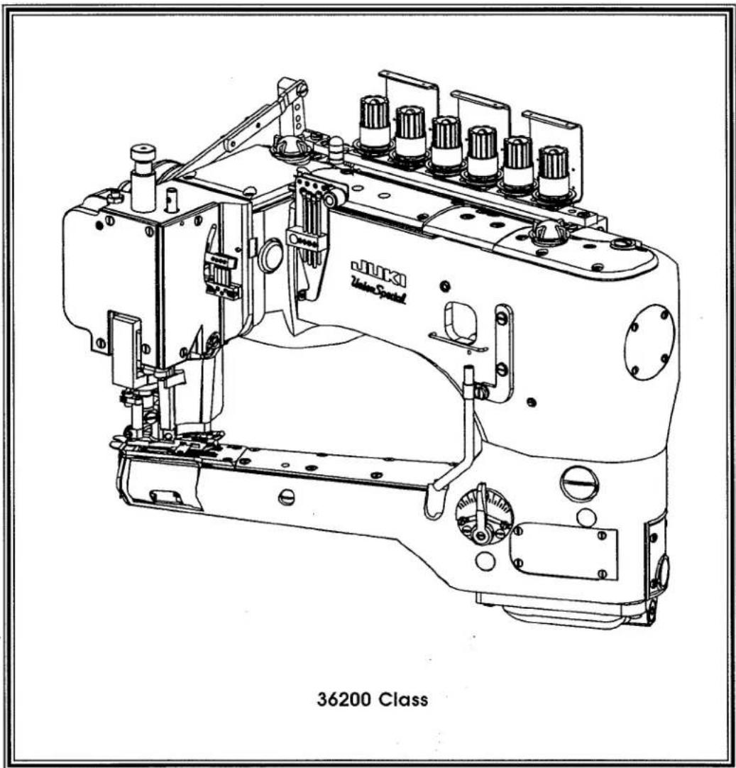
36200PX - Sewing machine Union Special - Free user manual and instructions
Find the device manual for free 36200PX Union Special in PDF.

| Product Type | Industrial Overlock Sewing Machine |
| Brand | Union Special |
| Model | 36200PX |
| Dimensions (approx.) | 660 mm x 350 mm x 300 mm |
| Weight | 28 kg |
| Power Supply | 220-240 V, 50/60 Hz |
| Power Consumption | 500 W |
| Stitch Types | 2-3-4 thread overlock, safety stitch, chain stitch |
| Stitch Length | 1 to 4 mm |
| Stitch Width | 3 to 7 mm |
| Max Speed | 7,000 stitches per minute |
| Differential Feed | Adjustable, 0.7 to 2.0 |
| Functions | Rolled hem, flat seaming, edge finishing |
| Needle System | DB x 1 or 134 needles |
| Lubrication | Automatic oiling system |
| Maintenance | Daily cleaning of lint and oiling |
| Safety Features | Protective finger guard, safety switch |
| Spare Parts Availability | Needles, knives, looper, presser foot |
| Included Accessories | Set of needles, screwdrivers, oiler |
| Manual Language | English (PDF) |
Frequently Asked Questions - 36200PX Union Special
User questions about 36200PX Union Special
0 question about this device. Answer the ones you know or ask your own.
Ask a new question about this device
Download the instructions for your Sewing machine in PDF format for free! Find your manual 36200PX - Union Special and take your electronic device back in hand. On this page are published all the documents necessary for the use of your device. 36200PX by Union Special.
USER MANUAL 36200PX Union Special
Union Special® INDUSTRIAL SEWING EQUIPMENT
ILLUSTRATED PARTS LIST
text_image
JUKI Yumu Special 36200 ClassMANUAL NO. PRT9201
STYLES
36200 AK
36200 PA
36200 PH
36200 PJ
36200 PM
36200 PX
36200 TA
36200 TH
36200 TJ
36200 TM
36200 TX
Third Edition Copyright 1994
By
Union Special Corporation Rights Reserved In All Countries
Printed in U.S.A. August 1994
PREFACE
This parts manual has been prepared to assist you in locating individual parts or assemblies on 36200 Series machines. It can be used in conjunction with Union Special Adjusting Manual IN9202.
It is the desire of Union Special that each machine run at its optimum performance. Parts listed in this manual are designed specifically for your machine and are manufactured with utmost precision to assure long lasting service.
This manual has been comprised on the basis of available information. Changes in design and/or improvements may incorporate a slight modification of configuration in illustrations or part numbers.
On the following pages are illustrations and terminology used in describing the parts used on 36200 Series machines.
SAFETY RULES

General Operating Directions
The sewing machines described in this instruction manual are prohibited from being put into service until it has been ascertained that the sewing units, in which these sewing machines will be built-in have conformed with the EC Council Directives (89/392/EEC, Annex II B).
- Before putting the machines described in this manual into service, carefully read the instructions. The starting of each machine is only permitted after taking notice of the instructions and by qualified operators.
IMPORTANT! Before putting the machine into service, also read the safety rules and instruction from the motor supplier.
-
Observe the national safety rules valid for your country.
-
Each machine is only allowed to be used as foreseen. The foreseen use of the particular machine is described in paragraph "STYLES OF MACHINES" of this instruction manual. Another use, going beyond the description, is not as foreseen.
-
All safety devices must be in position when the machine is ready for work or in operation. Operation of the machine without the appertaining safety devices is prohibited.
-
The following safety devices are components of the sewing machines: Sewing guard, needle lever eyelet guard, needle bar guard, needle break protection shield and handwheel-belt guard.
-
When gauge parts are exchanged (i.e. needle, presser foot, needle plate, feed dog and bobbin), during threading, when the operator leaves the workplace, during service work, the machine must be isolated form the mains by switching off the main switch or disconnecting the main plug. On mechanically operated clutch motors without a start inhibitor it is necessary to wait until the motor has stopped.
-
Wear safety glasses.
-
In case of machine conversions and changes all valid safety rules must be considered. Conversions and changes are made at your own risk.
-
Commissioning of the sewing head is prohibited until such time as the entire sewing unit is found to comply with EC regulations.
-
The warning hints in the instructions are marked with one of these two symbols:

Items require special attention

Danger of injury to operative or service staff
Be sure to observe and adhere to these indications and to the generally applicable regulations.
Special Operating Directions
- For the following the machine has to be disconnected from the power supply by turning off the main switch or by pulling out the main plug:
11.1 For threading needle(s), looper, spreader etc.
11.2 For replacing sewing tools such as needle, presser foot, throat plate, looper, spreader, feed dog, needle guard, folder, fabric guide etc.
11.3 When leaving the workplace and when the workplace is unattended.
11.4 For maintenance work.
11.5 When using clutch motors without actuation lock, wait until the motor is stopped totally.
General Maintenance Directions
- Maintenance, repair and conversion work (see item 8) must be done only by trained technicians or special skilled personnel under consideration of the instructions.
- Any work on the electrical equipment must be done by an electrician or under direction and supervision of special skilled personnel.
Special Maintenance Directions
- Work on parts and equipment under electrical tension is not permitted.
- Before doing maintenance and repair work on the pneumatic equipment, the machine has to be disconnected from the compressed air supply. In case of existing residual air pressure after disconnecting from compressed air supply (i.e. pneumatic equipment with air tank), the pressure has to be removed by bleeding.
Exceptions are only allowed for adjusting work and function checks done by special skilled personnel.
Standards
- The sewing machines described in this manual are built according to the following standards:
EN292-2 Safety of machinery-basic concepts, general principles for design.
IEC204-3-1/EN60204-3-1 Electrical equipment of industrial machines. Part 3: Particular requirements for sewing machines, units and systems.
CONTENTS
• IDENTIFICATION OF MACHINES .... 5
•CLASS DESCRIPTION 5
• STYLE OF MACHINES .... 5
• ILLUSTRATIONS .... 5
• ILLUSTRATIONS (CONT.) 6
• IDENTIFYING PARTS 6
- NEEDLES 6
• TERMS 6
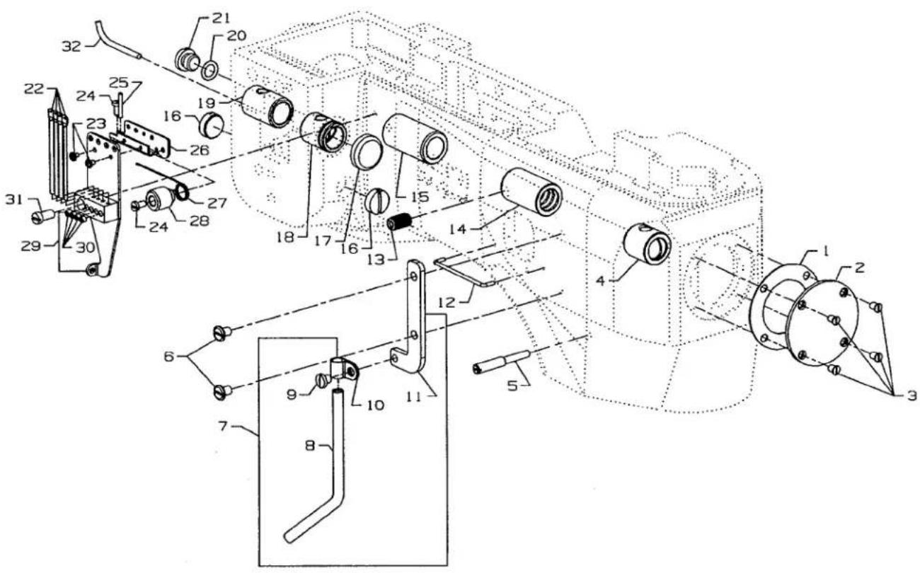
EXPLODED VIEWS
• OIL SIGHT GAUGES, TOP COVERS & MISCELLANEOUS TAKEUP & EYELET PARTS 9
• MAIN FRAME, BUSHINGS & MISCELLANEOUS EYELET & COVER PARTS 11
• MAIN SHAFT & MISCELLANEOUS OILING 13
• CRANKSHAFT & NEEDLE LEVER PARTS 15
• FOOT LIFTER & TENSION PARTS 17
• DETACHABLE HEAD, HEAD COVERS, NEEDLE BAR & NEEDLE BAR HEAD 19
• DIFFERENTIAL & MAIN FEED BARS, FEED DOGS & FEED LIFT ECCENTRIC ASSEMBLY 21
• FEED DRIVE ASSEMBLY, FEED ROCKER & LOOPER AVOID PARTS 23
• KNIFE DRIVING PARTS 25
• LOOPER ROCKER SHAFT & LOOPER ROCKER DRIVE PARTS 27
• LAP FORMER, MISCELLANEOUS CYLINDER COVERS, THROAT PLATE, & CHAIN CUTTING KNIFE 29
• CYLINDER BUSHINGS, DIFFERENTIAL FEED CONTROL ASSEMBLY & MISCELLANEOUS CYLINDER COVERS...... 31
• PRESSER FEET 33
• PRESSER FEET 35
• PRESSER FOOT SHOES 37
• THREAD STAND 39
• MISCELLANEOUS GAUGES & TAPE REEL PARTS 41
•DRIVE UNIT, BELT GUARD & TABLE MOUNTING PARTS 43
• NUMERICAL INDEX OF PARTS 44
• NUMERICAL INDEX OF PARTS 45
IDENTIFICATION OF MACHINES
Each UNION SPECIAL machine is identified by a style number, which is stamped into the style plate affixed to the middle of the machine under the tension assembly.
The serial number is stamped in the casting at the right rear base of the machine.
DESCRIPTION OF MACHINES
Feed-off-the-arm, high speed, medium throw, five or six thread machine. There are four needles and one retainer abreast, one looper and a manually adjusted differential feed control. There is an enclosed automatic lubricating system, filter type oil return pump, visual sight oil action and supply gauges. The maximum work space in front of the needles is 8 inches (203.2mm). Recommended speed - 4200 R.P.M. for all Styles. Styles starting with a 'T' are prepared for table installation and styles starting with a 'P' are prepared for pedestal installation.
STYLE OF MACHINES
| 36200AK | FLATSEAMER: Six thread dial adjusted differential feed. For simultaneously trimming and flatseaming knit undergarments, infants clothing and similar light to medium weight materials where closing elastic is required. Seam specifications 607-FSa-1. Components produce a .205" (5.2mm) wide seam. |
| 36200TA | FLATSEAMER: Six thread dial adjusted differential feed. For simultaneously trimming and flatseaming knit undergarments, infants clothing and similar light to medium weight materials where closing elastic is required. Seam specifications 607-FSa-1. Components produce a .205" (5.2mm) wide seam. Recommended needle 118 GKS, size 075/029, needle 36211, size 070/027. Maximum recommended speed 4200 RPM |
| 36200TH | LAP-FLATSEAMER: Six thread dial adjusted differential feed. For simultaneously trimming and closing the crotch seam on men's knit briefs when the added strength of a reinforced seam is required. Also used where crossing elastic and heavy seams, such as leg bindings is necessary. The right section of the sewing parts are raised .050" (1.27mm) to assure a better lap seam. Seam specifications 607-LSa-1. Components produce a .205" (5.2mm) wide seam. |
| 36200TJ | FLATSEAMER: Same as 36200TA except fitted with components that produce a .236" (6mm) wide seam. Six thread dial adjusted differential feed. For simultaneously trimming and flatseaming knit undergarments, infants clothing and similar light to medium weight materials where closing elastic is required. Seam specifications 607-FSa-1. Components produce a .205" (5.2mm) wide seam. |
| 36200TM | FLATSEAMER: Same as 36200TH except fitted with components that produce a .236" (6mm) wide seam. Six thread dial adjusted differential feed. For simultaneously trimming and closing the crotch seam on men's knit briefs when the added strength of a reinforced seam is required. Also used where crossing elastic and heavy seams, such as leg bindings is necessary. The right section of the sewing parts are raised .050" (1.27mm) to assure a better lap seam. Seam specifications 607-LSa-1. Components produce a .205" (5.3mm) wide seam. |
| 36200TX | TAPE-SEAMER: Five thread dial adjusted differential feed. Simultaneously trims, joins and tapes the front of knit briefs in one operation. Fitted with a taping foot that has the tape slot in front of the needle hole and folder that takes a 3/4" (19.0mm) knitted strip, cut with the wale, to produce a 7/16" (11.1mm) wide finished tape. Seam specifications 607-FSp-4 modified. Seam width is .205" (5.2mm). |
| 36200PA | FLATSEAMER: Same as 36200TA except prepared for pedestal installation. Six thread dial adjusted differential feed. For simultaneously trimming and flatseaming knit undergarments, infants clothing and similar light to medium weight materials where closing elastic is required. Seam specifications 607-FSa-1. Components produce a .205" (5.2mm) wide seam. |
| 36200PH | LAP-FLATSEAMER: Same as 36200TH except prepared for pedestal installation. Six thread dial adjusted differential feed. For simultaneously trimming and closing the crotch seam on men's knit briefs when the added strength of a reinforced seam is required. Also used where crossing elastic and heavy seams, such as leg bindings is necessary. The right section of the sewing parts are raised .050" (1.27mm) to assure a better lap seam. Seam specifications 607-LSa-1. Components produce a .205" (5.2mm) wide seam. |
| 36200PJ | FLATSEAMER: Same as 36200TJ except prepared for pedestal installation. Same as 36200TA except fitted with components that produce a .236" (6mm) wide seam. Six thread dial adjusted differential feed. For simultaneously trimming and flatseaming knit undergarments, infants clothing and similar light to medium weight materials where closing elastic is required. Seam specifications 607-FSa-1. Components produce a .205" (5.2mm) wide seam. |
| 36200PM | FLATSEAMER: Same as 36200TM except prepared for pedestal installation. Same as 36200TH except fitted with components that produce a .236" (6mm) wide seam. Six thread dial adjusted differential feed. For simultaneously trimming and closing the crotch seam on men's knit briefs when the added strength of a reinforced seam is required. Also used where crossing elastic and heavy seams, such as leg bindings is necessary. The right section of the sewing parts are raised .050" (1.27mm) to assure a better lap seam. Seam specifications 607-LSa-1. Components produce a .205" ( 5.2mm) wide seam. |
| 36200PX | TAPE-SEAMER: Same as 36200TX except prepared for pedestal installation. Five thread dial adjusted differential feed. Simultaneously trims, joins and tapes the front of knit briefs in one operation. Fitted with a taping foot that has the tape slot in front of the needle hole and folder that takes a 3/4" (19.0mm) knitted strip, cut with the wale, to produce a 7/16" (11.1mm) wide finished tape. Seam specifications 607-FSp-4 modified. Seam width is .205" (5.2mm). |
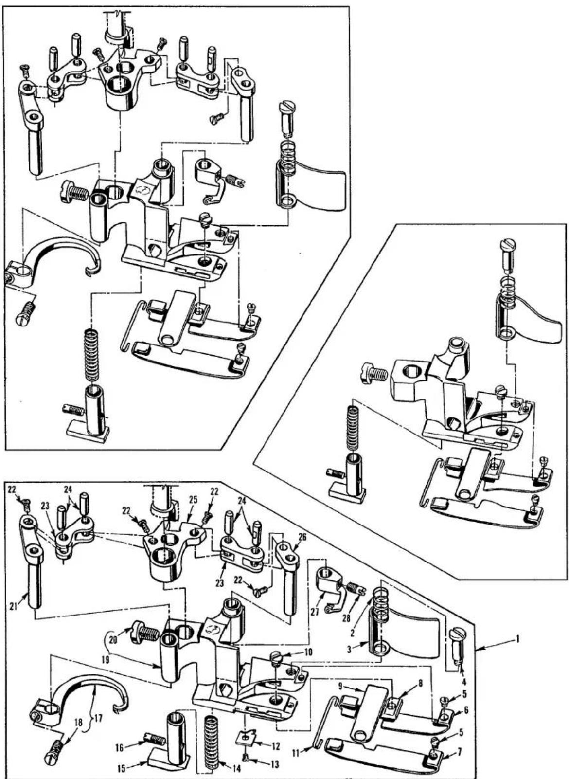
ILLUSTRATIONS
This manual has been arranged to simplify ordering repair parts. Exploded views of various sections of the mechanism are shown so that the parts may be seen in their actual position in the machine. On the page opposite the illustration will be found a listing of the parts with their part numbers, description and the number of pieces required in the particular view being shown.
Numbers in the first column are reference numbers only, and merely indicate the position of the part in the illustration. The reference number should never be used in ordering parts. Always use the part number listed in the second column.
Component parts of sub-assemblies which can be furnished for repairs are indicated by indenting their descriptions under the description of the main sub-assembly. As an example refer to the following text.
-
29126 EC Upper Looper Drive Shaft Assembly .... 1
-
22503 F Screw 1
-
39543 E Cam Follower Locking Clamp .... 1
It will be noted in the previous example that the cam follower, bushing and cam guide and the upper looper drive shaft are not listed. The reason is that replacement of these parts individually is not recommended, so the complete upper looper drive shaft assembly should be ordered.
When a part is common to all machines covered in this manual, no specific usage will be mentioned in the description. However, when the parts for the various machines are not the same, the specific usage will be mentioned in the description and, if necessary, the difference will be shown in the illustration.
A numerical index of all the parts shown in this manual is located at the back. This will facilitate locating the illustration and description when only a part number is known.
IDENTIFYING PARTS
Where the construction permits, each part is stamped with its part number. On some of the smaller parts and on those where construction does not permit, an identification letter is stamped in to distinguish the part from similar ones.
PLEASE NOTE: Part numbers represent the same part, regardless of which manual they appear. On all orders please include part number, name and style of machine for which the part was ordered.
NEEDLES
Each needle has both a type and size number. The type number denotes the kind of shank, point, length, groove, finish and other details. The size number, stamped on the needle shank, denotes the largest diameter of the blade measured between the shank and the eye. Collectively, the type number and size number represent the complete symbol which is given on the label of all needles packed and sold by Union Special.
| TYPE | DESCRIPTION | |
| 118GKS | 75/029 | Round shank, round point, extra short, double groove, struck groove, spotted, chromium plated needle. Sizes available 070/027, 075/029, 080/032. |
| 36211 | 80/032 | Retainer needle, no scarf, chromium plated. Sizes available 065/025, 070/027, 075/029. |
When changing the needle, make sure it is fully inserted in the needle driving arm before the nut is tightened.
To have needles promptly and accurately filled, an empty package, a needle sample, or the type and size number should be forwarded. Use the description on the label. A complete order should read as follows: "100 needles, type 130 GS, size 125/049".
APPLICATION
118GKS Recommended for Styles 36200AK, PA, PH, PJ, PM, TA, TH, TJ, TM.
118GKS Recommended for Styles 36200PX, TX.
TERMS
Prices are net cash and subject to change without notice. All shipments are forwarded F.O.B. shipping point. A charge is made to cover postage and insurance.

text_image
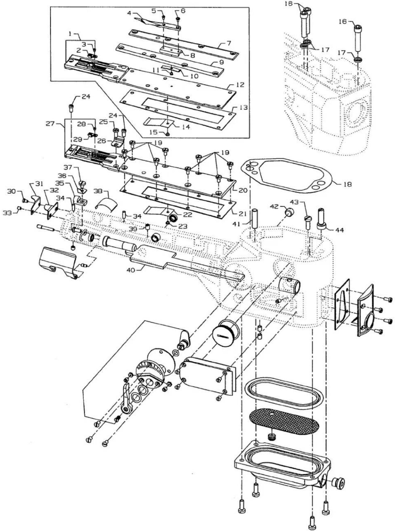
Technical diagram of a mechanical assembly with numbered components and exploded views, including a detailed view of the motor.OIL SIGHT GAUGES, TOP COVERS & MISCELLANEOUS TAKEUP & EYELET PARTS
| Ref. | Amt. | ||
| No. | Part No. | Description | Req. |
| 1. | 93 | Screw, for crank chamber cover | 5 |
| 2. | 35888 N | Crank Chamber Cover | 1 |
| 3. | B3530555000 | Oil Sight Gauge | 1 |
| 4. | 660-212 | "O"Ring | 1 |
| 5. | 22516 A | Screw | 4 |
| 6. | 93 A | Screw, for middle top cover | 2 |
| 7. | 90 | Screw, for spring | 2 |
| 8. | 35887 X | Top Cover, middle | 1 |
| 9. | 35887 AE | Top Cover, front | 1 |
| 10. | B3530555000 | Oil Sight Gauge | 1 |
| 11. | 660-212 | "O"Ring | 1 |
| 12. | 22539 M | Plug Screw | 1 |
| 13. | 22516 A | Screw, for front top cover | 6 |
| 14. | 73 C | Screw | 1 |
| 15. | 36256 | Cover Thread Take-up Eyelet | 1 |
| 16. | 29476XC | Cast-Off Plate Assembly | 1 |
| 17. | 22 KH | Screw, for cast-off | 2 |
| 18. | 36204 | Cast-off | 1 |
| 19. | 73 A | Screw, for cast-off plate eyelets | 2 |
| 20. | 52958 F | Cast-off Plate Eyelet, rear | 1 |
| 21. | 52958 C | Cast-off Plate Eyelet, front | 1 |
| 22. | 36204 A | Cast-off Plate | 1 |
| 23. | 36256 A | Cover Thread Take-up Eyelet Holder | 1 |
| 24. | 22839 | Screw | 2 |
| 25. | 35887 AG | Gasket, for front top cover | 1 |
| 26. | 22564 B | Screw, for middle cover hinge | 3 |
| 27. | 35887 R | Middle Cover Hinge | 1 |
| 28. | 41071 G | Nut, for top middle cover spring screw | 2 |
| 29. | 35887 M | Spring, for middle top cover | 1 |
| 30. | 12934 A | Nut, for top middle cover spring screw | 2 |
| 31. | 35888 T | Gasket, for crank chamber | 1 |
| 32. | 22569 B | Screw, for bushing housing | 1 |
| 33. | 36290 D | Bushing Housing, includes bushing | 1 |
| 34. | 56390 E | Gasket, for bushing housing | 1 |
| 35. | LA528 | Directional Label | 1 |
| 36. | 660-935 | "O"Ring | 1 |
| 37. | CL21 | Oil Wick | 1 |
| 38. | 35889 H | Oil Shield | 1 |
| 39. | 6042 A | Washer, for screw | 2 |
| 40. | 22759 A | Screw, for connecting head to main frame | 2 |
| 41. | 22711 | Screw, for oil wick | 1 |
| 42. | 22539 AA | Plug Screw | 1 |
| 43. | 36293 B | Oil Sight Gauge | 1 |
| 44. | 36293 E | Oil Level Indicator | 1 |
| 45. | 39593 C | Oil Gauge Float | 1 |
| 46. | 93 | Screw, for oil pump housing | 2 |
| 47. | 35890 P | Bushing | 1 |
| 48. | 35893 G | Seal, Upper | 1 |
| 49. | 35893 H | Seal, Lower | 1 |
text_image
Technical diagram of a mechanical assembly with numbered components and exploded view, likely for engineering or manufacturing documentation.MAIN FRAME, BUSHINGS & MISCELLANEOUS EYELET & COVER PARTS
| Ref. | Amt. | ||
| No. | Part No. | Description | Req. |
- 35887 AF Gasket, end cover.... 1
- 35887 Z End Cover 1
- 22564 B Screw, end cover 4
- 36290 B Main Shaft Bushing, front 1
- 22791 D Screw, for looper drive lever shaft.... 1
- 22829 Screw, looper thread shield 2
- 29105 BH Looper Thread Shield 1
- 35866 A Tube 1
- SS7110510SP Screw 1
- 35866 B Tube Clamp 1
- 35883 AL Support.... 1
- 35781 D Looper Thread Guide Wire 1
- 62271 B Thread Guide 1
- 36290 A Main Shaft Bushing, rear 1
- 35890 E Crankshaft Bushing, front 1
- 22539 T Plug Screw 2
- 35761 D Bushing Cap.... 1
- 35760 D Needle Lever Shaft Bushing, front .... 1
- 36260 Needle Lever Shaft Bushing, rear 1
- 660-206 Rubber "O" Ring 1
- 22733 B Oil Drain Screw 1
- 36271 A Frame Needle Thread Eyelet 4
- 73 A Screw, for needle thread eyelet 2
- 22768 B Screw, for unlocking spring height adjusting.... 1
- 22799 B Screw 2
- 36271 G Stitch Unlocker Mounting Bracket 1
- 36271 E Unlocking Spring.... 1
- 36271 H Spring Holder 1
- 36271 Needle Thread Eyelet 1
- 28 C Screw 4
- 22569 D Screw, for needle thread eyelet 1
- CL21 Oil Wick 1
text_image
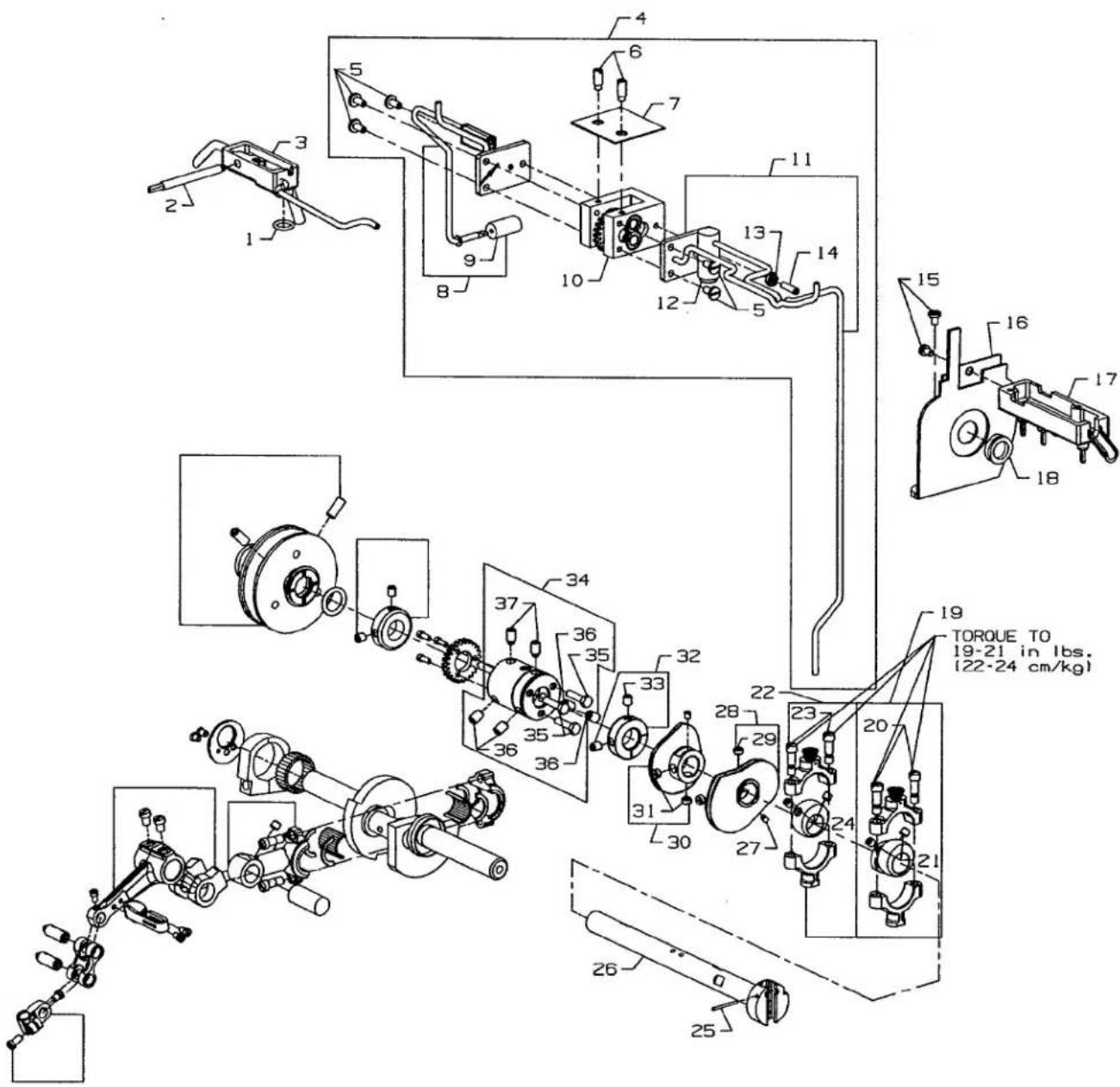
Technical schematic diagram of a mechanical assembly with numbered components and torque specifications in Chinese.MAIN SHAFT & MISCELLANEOUS OILING
| Ref. | Amt. | ||
| No. | Part No. | Description | Req. |
1 660-207 Oil Seal Ring.... 1
2 35897 BU Reservoir Outlet Tube 1
3 35894 J Oil Reservoir, back 1
4 29472 Y Pump Assembly 1
5 22585 A Screw, for housing cover 5
6 21756 G Vent Screw 2
7 35897 BW Gasket 1
8 36297 J Housing Cover and Oil Tube, rear 1
9 35897 BV Intake Filter 1
10 29472 AC Pump Body and Gear Assembly 1
11 36297 M Housing Cover and Oil Tube, front 1
12 22571 B Plug Screw 1
13 41071 G Nut 1
14 22565 A Screw 1
15 90 Screw, for take-up shield 2
16 36261 A Take-up Shield Assembly 1
17 35894 L Oil Reservoir, front 1
18 666-338 Oil Seal Ring 1
19 29101 J Feed Drive Eccentric Assembly 1
20 22587 E Screw 2
21 22894 W Set Screw 2
22 29103 T Feed Lift Eccentric Assembly 1
23 22587 E Screw 2
24 22894 W Set Screw 2
25 660-219 P Roll Pin 1
26 36222 C Main Shaft 1
27 22801 Screw 2
28 36223 Double Disc Take-up 1
29 22580 Screw 2
30 36223 A Cover Thread Take-up....1
31 22580 Screw 2
32 35895 Y Crankshaft Thrust Collar 1
33 22894 AM Screw 2
34 35895 X Main Shaft Coupling 1
35 22519 F Screw 3
36 22894 J Set Screw 4
37 22894 K Spot Screw 2
text_image
Technical schematic diagram of a mechanical assembly with numbered components and torque specificationsCRANKSHAFT & NEEDLE LEVER PARTS
| Ref. | Amt. | ||
| No. | Part No. | Description | Req. |
- 35897 BY Pump Driving Gear 1
- 22797 Screw 3
- 35895 Y Crankshaft Thrust Collar 1
- 22894 AM Screw 2
- 660-202 Oil Seal Ring 1
- 36221 D Pulley, for all Styles.... 1
- 22894 E Screw, for adjustable pulley 2
- 22766 Screw 2
- 36251 N Needle Bearing Retaining Plate 1
- 36251 M Eccentric Bearing 1
- 36263 Needle Bearing Rollers 28
- 35763 G Needle Bearing Retaining Ring 4
- 35862 A Needle Lever Connecting Rod.... 1
- 22587 B Screw 2
- 22894 W Screw 1
- 36222 A Crankshaft.... 1
- 35763 F Needle Bearing Rollers 28
- 35847 X Needle Lever Connecting Rod Pin 1
- 77 Screw 2
- 36264 D Needle Lever Thread Eyelet 1
- 51054 A Link Pin.... 2
- 22564 Screw 1
- 51254 K Needle Bar Connection.... 1
- 22562 A Screw 1
- 56354 D Needle Bar Link 1
- 77 Screw 1
- 35815 C Needle Lever 1
- 22596 B Screw 2

text_image
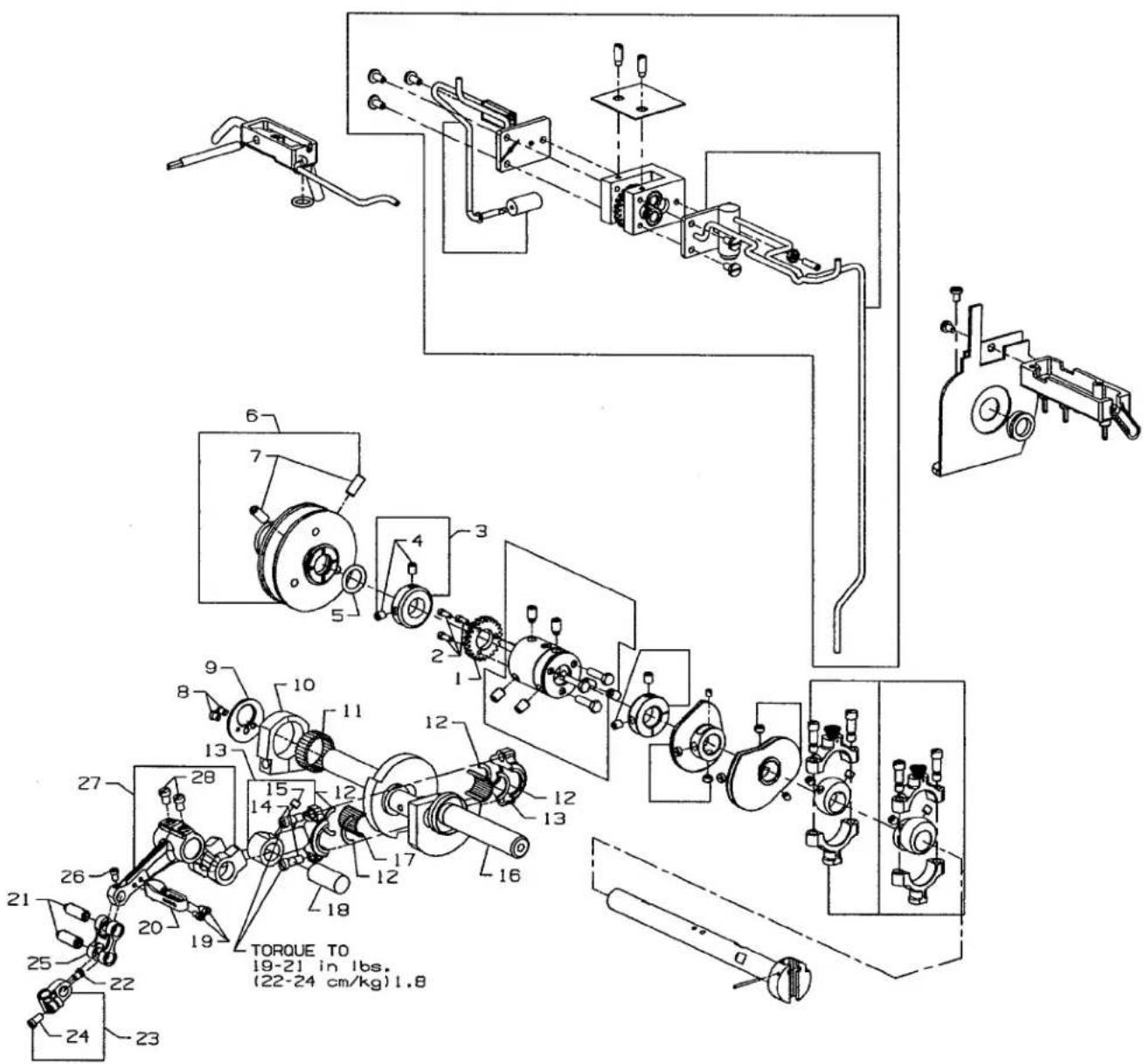
Technical schematic diagram of a mechanical assembly with numbered components and exploded viewsFOOT LIFTER & TENSION PARTS
| Ref. | Amt. | ||
| No. | Part No. | Description | Req. |
| 1. | 36280 V | Lifter Lever Link Assembly | 1 |
| 2. | 22585 C | Screw | 2 |
| 3. | 36280 U | Lifter Lever Link | 1 |
| 4. | 86 | Screw | 2 |
| 5. | 36280 W | Presser Bar Lifter Lever | 1 |
| 6. | 22839 D | Screw | 1 |
| *7. | 36280 T | Lifter Lever Connecting Link | 1 |
| *8. | 36280 S | Presser Foot Connection Lifter Lever | 1 |
| *9. | 660-254 C | Retaining Ring | 2 |
| *10. | 22517 | Screw, for presser foot lifter bearing bracket | 1 |
| *11. | 36280 N | Presser Foot Lifter Bearing Bracket | 1 |
| *12. | 255 | Screw | 1 |
| 13. | 36298 F | Tension Support | 1 |
| 14. | 36298 G | Tension Thread Eyelet | 3 |
| 15. | 22562 A | Screw, for tension post | 6 |
| 16. | 94 | Screw, for tension support | 2 |
| 17. | 36292 M | Tension Plate Bracket | 2 |
| 18. | 22517 | Screw, for tension plate bracket | 2 |
| 19. | 35792 T | Tension Disc Release Pin | 7 |
| 20. | 36292 N | Tension Release Shaft | 1 |
| 21. | 22784 F | Screw | 1 |
| 22. | 36292 K | Spring, for tension release shaft | 1 |
| 23. | 22519 | Screw, for stop plunger segment pin | 1 |
| 24. | 36280 A | Presser Foot Lifter Stop Plunger | 1 |
| 25. | 258 A | Nut | 1 |
| 26. | 36280 C | Stop Plunger Segment | 1 |
| 27. | 36280 D | Stop Plunger Segment Pin | 1 |
| 28. | C50092 S | Tension Nut | 6 |
| 29. | 39592 AK | Tension Spring Ferrule | 6 |
| 30. | 51292 F-2 | Tension Spring, for cover thread | 1 |
| 51292 F-4 | Tension Spring, for looper thread | 1 | |
| 51292 F-5 | Tension Spring, for needle thread | 4 | |
| 31. | 56392 F | Shield, for tension spring | 6 |
| 32. | 35792 | Tension Disc, large | 6 |
| 33. | 109 | Tension Disc, small | 6 |
| 34. | 36292 P | Tension Post | 6 |
*Available on Styles 36200 TA, TH, TJ, TM, TX

text_image
Technical schematic diagram of a mechanical assembly with numbered components and exploded views* Items 22, 23, 24, 25, and spanner wrench 21388Y are all part of kit 29480AZJ
DETACHABLE HEAD, HEAD COVERS, NEEDLE BAR & NEEDLE BAR HEAD
| Ref. No. | Part No. | Description | Amt. Req. |
| 1. | 36289 B | Baffle Plate | 1 |
| 2. | 36280 J | Presser Bar Lifter Lever | 1 |
| 3. | 36289 H | Gasket, for front head cover | 1 |
| 4. | 36289 | Head Cover, front | 1 |
| 5. | 22524 | Screw, for front head cover | 2 |
| 6. | 36264 B | Needle Thread Strike-off Pin | 4 |
| 7. | 28 | Screw, for needle thread take-up | 2 |
| 8. | 36264 E | Needle Thread Take-up, complete | 1 |
| 9. | 36264 F | Strike-off Pin Holder | 1 |
| 10. | 22738 C | Screw, for needle thread take-up | 2 |
| 11. | 28 | Screw, for cover thread eyelet | 1 |
| 12. | 51259 | Cover Thread Eyelet, for all Styles except 36200 PX, TX | 1 |
| 13. | 28 A | Screw, for needle thread take-up | 4 |
| 14. | 36229 B | Detachable Sewing Head | 1 |
| 15. | 36278 A | Presser Bar Bushing | 1 |
| 16. | 35859 D | Needle Bar Bushing, upper | 1 |
| 17. | 22524 | Screw | 2 |
| 18. | 35767 | Sewing Head Key | 2 |
| 19. | 35859 J | Needle Bar Bushing, lower | 1 |
| 20. | 36251 D | Cover Thread Carrier and Hook Driving Sleeve Bushing | 1 |
| 21. | 660-261 | Retaining Ring | 1 |
| 22. | 22777 B | Screw, for frame chip guard | 1 |
| 23. | 36279 L | Spring, for frame chip guard | 1 |
| 24. | 36279 N | Frame Chip Guard, for Styles 36200 AK, PA, PH, PJ, PM, TA, TH, TJ, TM | 1 |
| 25. | 36279 M | Washer, for frame chip guard | 1 |
| 26. | 22513 | Screw, for oil deflector | 1 |
| 27. | 8372 A | Washer | 1 |
| 28. | 36294 C | Oil Deflector | 1 |
| 29. | 22881 A | Screw, for right presser foot guide | 1 |
| 30. | 36278 K | Presser Foot Guide, right | 1 |
| 31. | 35817 E | Needle Bar | 1 |
| 32. | 36278 | Presser Bar | 1 |
| 33. | 36278 L | Presser Foot Guide, left | 1 |
| 34. | 22653 B-8 | Screw, for left presser foot guide | 2 |
| 35. | 36218 | Needle Head, for all Styles except 36200 PJ, PM, TJ, TM | 1 |
| - | 36218 J | Needle Head, for Styles 36200 PJ, PM, TJ, TM | 1 |
| 36. | 22738 H | Screw, for needles and retainer | 5 |
| 37. | WO3 | Yarn, Oil Wick | 1 |
| 38. | 35897 CK | Oil Wick Hook | 1 |
| 39. | 22524 | Screw, for left head cover | 4 |
| 40. | 36289 A | Head Cover, left | 1 |
| 41. | 36289 J | Gasket, for left head cover | 1 |
| 42. | 6042 A | Washer | 1 |
| 43. | 318 | Screw, for connecting head to main frame | 1 |
| 44. | 664 F-16 | Taper Pin | 1 |
| 45. | 36278 H | Presser Bar Guide Stud | 1 |
| 46. | 22560 A | Screw, for presser bar guide stud | 1 |
| 47. | 12538 | Nut, for presser bar guide stud | 1 |
| 48. | 36278 F | Spring, for presser bar | 1 |
| 49. | 36278 M | Presser Bar Regulating Screw | 1 |
| 50. | 36294 B | Oil Guard | 1 |
| 51. | 22585 C | Screw, for oil guard | 1 |
| 52. | 35880 M | Lifter Lever Link Connection | 1 |
| 53. | 22894 J | Screw | 1 |

text_image
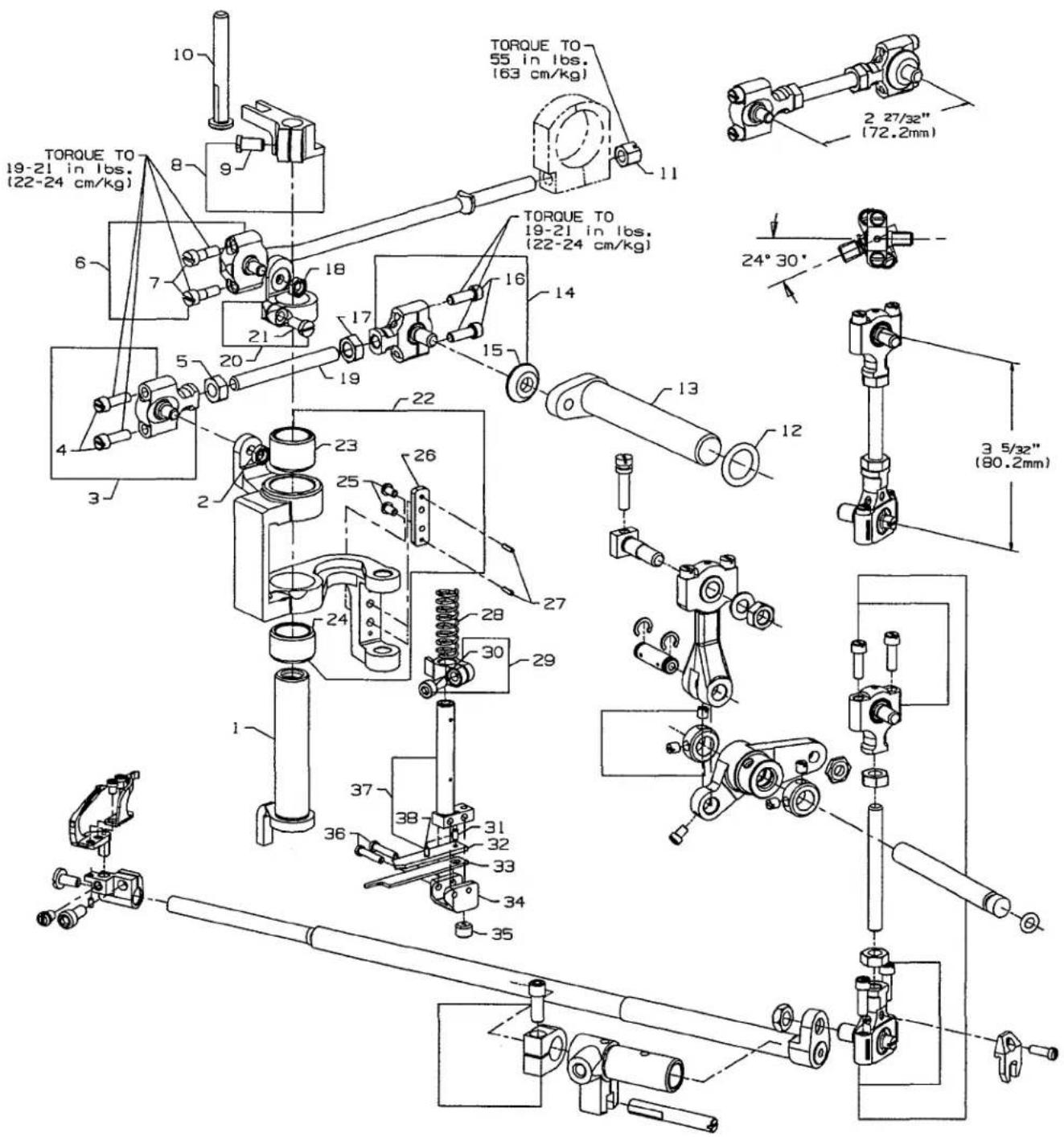
TORQUE TO 28-30 in. lbs. (32-35 cm/kg) TORQUE TO 19-21 in. lbs. (22-24 cm/kg) TORQUE TO 8 in. lbs. (9 cm/kg) TORQUE TO 19-21 in. lbs. (22-24 cm/kg) TORQUE TO 8 in. lbs. (9 cm/kg) 4 27/32 (123.16mm) 4 25/32 (121.95mm)DIFFERENTIAL & MAIN FEED BARS, FEED DOGS & FEED LIFT ECCENTRIC ASSEMBLY
| Ref. No. | Part No. | Description | Amt. Req. |
| 1. | 22845 M | Screw, for differential feed bar driving link | 1 |
| 2. | 36236 F | Differential Feed Bar Driving Link | 1 |
| 3. | 36234 M | Feed Bar Eccentric Stud | 1 |
| 4. | 660-220 | "O"Ring | 1 |
| 5. | 36234 F | Differential Feed Bar | 1 |
| 6. | 36234 G | Feed Bar Plate | 1 |
| 7. | 22587 H | Screw | 2 |
| 8. | 22528 | Screw, for differential feed dog | 1 |
| 9. | 36226 A | Differential Feed Dog, marked "FV", 14 teeth per inch, for Styles 36200 AK, PA, PJ, PX, TA, TJ, TX | 1 |
| - | 36226 B | Differential Feed Dog, marked "PB", 16 teeth per inch | 1 |
| - | 36226 H | Differential Feed Dog, marked "PQ", 14 teeth per inch, .050" (1.27mm) step on right side, for Styles 36200 PH, TH | 1 |
| - | 36226 J | Differential Feed Dog, marked "VU", 16 teeth per inch, .050" (1.27mm) step on right side, for Styles 36200 PM, TM | 1 |
| 10. | 87 U | Screw, for needle guard | 1 |
| 11. | 36225 | Needle Guard | 1 |
| 12. | 22528 | Screw, for main feed dog | 1 |
| 13. | 36205 A | Main Feed Dog, marked "PK", 14 teeth per inch, for Styles 36200 AK, PA, PJ, PX, TA, TJ, TX | 1 |
| - | 36205 B | Main Feed Dog, marked "PL", 16 teeth per inch | 1 |
| - | 36205 H | Main Feed Dog, marked "PR", 14 teeth per inch, .050" (1.27mm) step on right side, for Styles 36200 PH, TH | 1 |
| - | 36205 J | Main Feed Dog, marked "VV", 16 teeth per inch, .050" (1.27mm) step on right side, for Styles 36200 PM, TM | 1 |
| 14. | 36234 E | Main Feed Bar | 1 |
| 15. | 22578 H | Screw | 2 |
| 16. | 36234 G | Feed Bar Plate | 1 |
| 17. | 36234 C | Feed Bar Slide Block | 1 |
| 18. | 36236 H | Bushing | 2 |
| 19. | 36236 G | Driving Link Stud | 2 |
| 20. | 33174 B | Screw | 1 |
| 21. | 36236 E | Main Feed Bar Drive Link | 1 |
| 22. | 62238 A | Link Pin | 1 |
| 23. | 29478 CS | Feed Lift Eccentric Assembly | 1 |
| 24. | 29103 T | Feed Lift Eccentric Assembly Ball Joint | 1 |
| 25. | 22894 W | Set Screw | 2 |
| 26. | 22587 E | Screw | 2 |
| 27. | 269 | Nut, left thread | 1 |
| 28. | 36244 | Connecting Rod | 1 |
| 29. | 18 | Nut, right thread | 1 |
| 30. | 36244 A | Ball Joint, complete | 1 |
| 31. | 22729 C | Screw | 2 |
| 32. | 41255 B | Ball Fork | 1 |
| 33. | 22747 | Screw, for ball fork | 1 |

text_image
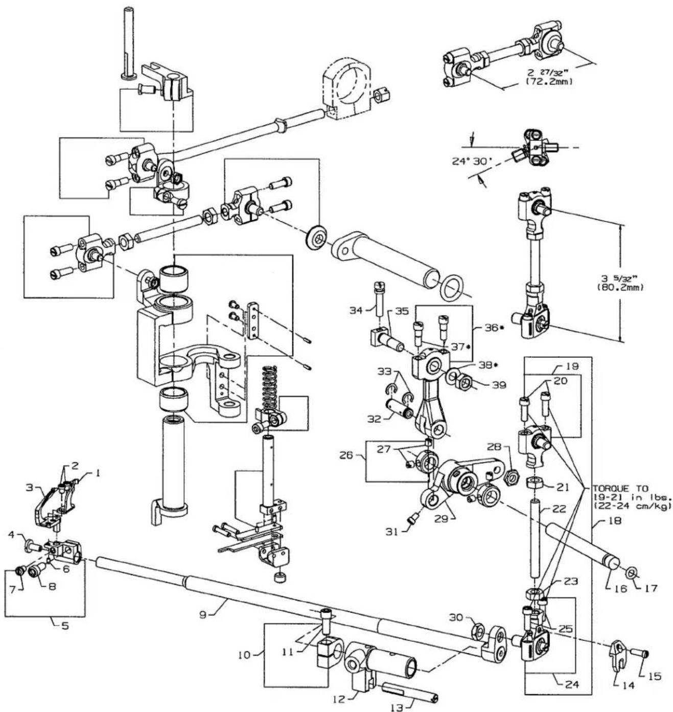
TORQUE TO 28-30 in. lbs. (32-35 cm/kg) TORQUE TO 19-21 in. lbs. (22-24 cm/kg) TORQUE TO 28-30 in. lbs. (32-35 cm/kg) TORQUE TO 8 in. lbs. (9 cm/kg) TORQUE TO 19-21 in. lbs. (22-24 cm/kg) TORQUE TO 8 in. lbs. (9 cm/kg) TORQUE TO 19-21 in. lbs. (22-24 cm/kg) 12 13 14 15 16 17 18 19 20 21 22 23 24 25 26 27 28 29 30 31 32 33 34 35 36 37 38 39 40 41 42 43 44 45 46 47 48 49 50 51 52 53 54 55 56 57 58 59 60 61 62 63 64 65 66 67 68 69 70 71 72 73 74 75 76 77 78 79 80 81 82 83 84 85 86 87 88 89 90 91 92 93 94 95 96 97 98 99 100FEED DRIVE ASSEMBLY, FEED ROCKER & LOOPER AVOID PARTS
| Ref. | Amt. | ||
| No. | Part No. | Description | Req. |
| 1. | 660-207 | Oil Seal Ring | 1 |
| 2. | 36236 A | Feed Rocker Shaft | 1 |
| 3. | 36237 | Differential Feed Adjusting Lever | 1 |
| 4. | 36237 A | Differential Feed Adjusting Link | 1 |
| 5. | 22504 C | Screw | 1 |
| 6. | 36236 J | Differential Driving Link Stud | 1 |
| 7. | 36236 K | Differential Feed Driving Link Slide Block | 1 |
| 8. | 36236 | Feed Rocker | 1 |
| 9. | 77 | Screw | 2 |
| 10. | 36236 B | Bushing | 1 |
| 11. | 22733 G | Screw | 1 |
| 12. | 29478 CT | Feed Drive Assembly | 1 |
| 13. | 29101 J | Feed Drive Eccentric Assembly | 1 |
| 14. | 22587 E | Screw | 2 |
| 15. | 22894 W | Set Screw | 2 |
| 16. | 269 | Nut, left thread | 1 |
| 17. | 43246 | Connecting Rod | 1 |
| 18. | 18 | Nut, right thread | 1 |
| 19. | 35846 | Ball Joint | 1 |
| 20. | 22729 C | Screw | 2 |
| 21. | 35846 B | Washer | 1 |
| 22. | 35866 | Nut | 1 |
| 23. | 36236 B | Bushing | 1 |
| 24. | 22733 G | Screw | 1 |
| 25. | 35766 B | Nut | 1 |
| 26. | 35842 J | Feed Drive and Looper Avoid Drive Lever | 1 |
| 27. | 36236 A | Feed Drive Shaft | 1 |
| 28. | 660-207 | Oil Seal Ring | 1 |
| 29. | 35836 C | Screw, for feed rocker driving link | 1 |
| 30. | 36236 H | Bushing | 1 |
| 31. | 258 | Nut | 1 |
| 32. | 6042 A | Washer | 1 |
| 33. | 36236 C | Feed Rocker Driving Link | 1 |
| 34. | 62238 A | Link Pin | 1 |
| 35. | 29478 FF | Looper Drive Shaft Cross Head Connecting Rod Assembly | 1 |
| 36. | 35851 N | Screw | 2 |
| 37. | 35851 M | Connecting Rod | 1 |
text_image
TORQUE TO 19-21 in lbs. (22-24 cm/kg) TORQUE TO 55 in lbs. (63 cm/kg) 2 27/32" (72.2mm) 24° 30' 3 5/32" (80.2mm)KNIFE DRIVING PARTS
| Ref.No. | Part No. | Description | Amt.Req. |
| 1. | 36251 B | Cover Thread Carrier and Hook Driving Sleeve | 1 |
| 2. | 12934 A | Nut | 1 |
| 3. | 52848 B | Knife Drive Connection Ball Joint, left | 1 |
| 4. | 22729 C | Screw | 2 |
| 5. | 18 | Nut, right thread | 1 |
| 6. | 36251 P | CoverThread Carrier and Hook Driving Connection Rod Ball Joint | 1 |
| 7. | 97 A | Screw | 2 |
| 8. | 36278 J | Presser Bar Guide | 1 |
| 9. | 22569G | Screw | 1 |
| 10. | 36278 H | Presser Bar Guide Stud | 1 |
| 11. | 52841 H | Nut | 1 |
| 12. | 660-202 | Oil Seal Ring | 1 |
| 13. | 36261 | Knife Drive Lever | 1 |
| 14. | 52848 C | Knife Drive Connection Ball Joint, right | 1 |
| 15. | 36 G | Washer | 1 |
| 16. | 22729 C | Screw | 2 |
| 17. | 269 | Nut, left thread | 1 |
| 18. | 12934 A | Nut | 1 |
| 19. | 4761 | Knife Drive Connecting Rod | 1 |
| 20. | 36251 C | Sleeve Driving Lever, for Styles 36200 AK, PA, PH, PX, TA, TH, TX | 1 |
| - | 36251 V | Sleeve Driving Lever, for Styles 36200 PJ, PM, TJ, TM | 1 |
| 21. | 22585 | Screw | 1 |
| 22. | 36273 M | Knife Driving Bracket | 1 |
| 23. | 36273 F | Bushing | 1 |
| 24. | 36273 N | Bushing | 1 |
| 25. | 605 A | Screw | 2 |
| 26. | 36273 J | Knife Holder Guide Plate | 1 |
| 27. | 660-219 D | Roll Pin | 2 |
| 28. | 36273 C | Knife Holder Spring | 1 |
| 29. | 36273 K | Knife Holder Guide Collar | 1 |
| 30. | 22729 M | Screw | 1 |
| 31. | 22799 N | Screw | 1 |
| 32. | 36273 D | Knife Support | 1 |
| 33. | 36270 B | Knife, upper | 1 |
| 34. | 36273 G | Knife Holder | 1 |
| 35. | 22894 X | Screw | 1 |
| 36. | 22767 A | Screw | 2 |
| 37. | 36273 A | Knife Holder Shank | 1 |
| 38. | 1096 B | Screw | 1 |
text_image
Technical schematic diagram of a mechanical assembly with numbered components and dimensional annotations in millimeters.*Items 36, 37, 38, are part of Looper Drive connection kit 29478FG
| Ref. | Amt. | ||
| No. | Part No. | Description | Req. |
| 1. | 36210 | Looper Mounted Needle Guard, marked "FZ" | 1 |
| 2. | 604 | Screw, for needle guard | 2 |
| 3. | 36208 A | Looper | 1 |
| 4. | 22585 A | Screw | 1 |
| 5. | 36248 | Looper Holder | 1 |
| 6. | 1096 B | Looper Adjusting Screw | 1 |
| 7. | 22564 D | Screw | 1 |
| 8. | 22652 A-6 | Screw | 1 |
| 9. | 36249 | Looper Rocker Shaft | 1 |
| 10. | 35751 G | Looper Shaft Collar | 1 |
| 11. | 22572 B | Screw | 1 |
| 12. | 36249 B | Looper Shaft Sleeve | 1 |
| 13. | 36278 C | Guide Stud | 1 |
| 14. | 41255 B | Ball Fork | 1 |
| 15. | 22747 | Screw | 1 |
| 16. | 36253 B | Looper Drive Lever Shaft | 1 |
| 17. | 660-221 | Oil Seal Ring | 1 |
| 18. | 29478 CU | Looper Drive Connecting Rod Assembly | 1 |
| 19. | 35851 L | Ball Joint, upper | 1 |
| 20. | 22729 C | Screw | 2 |
| 21. | 269 | Nut, left thread | 1 |
| 22. | 4761 | Connecting Rod | 1 |
| 23. | 18 | Nut, right thread | 1 |
| 24. | 39145 A | Ball Joint, lower | 1 |
| 25. | 22729 C | Screw | 2 |
| 26. | 12865 | Collar | 2 |
| 27. | 88 | Screw | 2 |
| 28. | 15037 A | Nut | 1 |
| 29. | 36253 A | Looper Drive Lever | 1 |
| 30. | 258 A | Nut | 1 |
| 31. | 77 | Screw | 1 |
| 32. | 52336 | Link Pin | 1 |
| 33. | 660-215 | Retaining Ring | 2 |
| 34. | 22795 B | Screw | 1 |
| 35. | 36253 G | Looper Drive Crank Stud | 1 |
| 36. | 36245 B | Looper Drive Connecting Rod and Ferrule Sub-Assembly | 1 |
| 37. | 97 A | Screw | 1 |
| 38. | 53636 C | Washer | 1 |
| 39. | 269 | Nut, left thread | 1 |
text_image
Exploded view diagram of a mechanical assembly with numbered components and exploded viewsLAP FORMER, MISCELLANEOUS CYLINDER COVERS, THROAT PLATE, & CHAIN CUTTING KNIFE
| Ref. | Amt. | ||
| No. | Part No. | Description | Req. |
| 1. | 36224 H | Throat Plate, .050" (1.27mm) step on right side, Styles 36200 PH, TH | 1 |
| - | 36224 K | Throat Plate, .050" (1.27mm) step on right side, Styles 36200 PM, TM | 1 |
| 2. | 36240 | Stitch Tongue, marked "D", for Styles 36200 PH, TH | 1 |
| - | 36240 J | Stitch Tongue, marked "AC", for Styles 36200 PM, TM | 1 |
| 3. | 22716 A | Screw, stitch tongue | 1 |
| 4. | 23420 DB | Lap Former | 1 |
| 5. | 22738 B | Screw, for lap former | 1 |
| 6. | 73 A | Screw, for lap former | 1 |
| 7. | 36283 J | Gib, right | 1 |
| 8. | 23423 X | Lap Former Slide Block | 1 |
| 9. | 36283 H | Gib, left | 1 |
| 10. | 23424 Z | Spring, for lap former slide block | 1 |
| 11. | 22716 A | Screw, for lap former slide block spring | 1 |
| 12. | 36283 G | Cylinder Cover | 1 |
| 13. | 36283 F | Gasket, for cylinder cover | 1 |
| 14. | 36284 E | Upper Lint Shield | 1 |
| 15. | 22798 | Screw, upper lint shield | 1 |
| 16. | 22653 E-24 | Screw, for joining cylinder to main frame | 3 |
| 17. | 35876 U | Washer | 3 |
| 18. | 36284 | Gasket | 1 |
| 19. | 98 A | Screw, for cylinder cover | 8 |
| 20. | 36283 E | Cylinder Cover, for all Styles except 36200 PH, PM, TH, TM | 1 |
| 21. | 36283 F | Gasket, for cylinder cover | 1 |
| 22. | 36284 E | Upper Lint Shield | 1 |
| 23. | 22798 | Screw, for upper lint shield | 1 |
| 24. | 22562 A | Screw, for throat plate | 3 |
| 25. | 22849 | Screw, for edge guide | 1 |
| 26. | 36203 | Edge Guide, for Styles 36200 AK, PA, PJ, TA, TJ | 1 |
| 27. | C36224 A | Throat Plate, for Styles 36200 AK, PA, PX, TA, TX | 1 |
| - | C36224 J | Throat Plate, for Styles 36200 PJ, TJ | 1 |
| 28. | 22716 A | Screw, for stitch tongue | 1 |
| 29. | 36240 | Stitch Tongue, marked "D", for Styles 36200 AK, PA, PX, TA, TX | 1 |
| - | 36240 J | Stitch Tongue, marked "AC", for Styles 36200 PJ, TJ | 1 |
| 30. | 22 KH | Screw, for chain cutting knife | 1 |
| 31. | 36296 B | Guard, for chain cutting knife | 1 |
| 32. | 36296 A | Chain Cutting Knife | 1 |
| 33. | 22801 | Screw, for chain cutting knife | 1 |
| 34. | 36251 K | Dowel Pin | 2 |
| 35. | 36283 C | Cylinder Hinged Spring Support Stud | 1 |
| 36. | 36283 B | Spring | 1 |
| 37. | 22585 C | Screw, spring | 1 |
| 38. | 35884 M | Lower Lint Shield | 1 |
| 39. | 531 | Screw | 1 |
| 40. | 666-341 | Felt | 1 |
| 41. | 22571 A | Plug Screw | 1 |
| 42. | 667 D-16 | Dowel Pin | 1 |
| 43. | 22596 | Screw, for feed bar eccentric stud | 1 |
| 44. | 36229 A-1 | Cylinder Alignment Eccentric Pin | 1 |
*Indicates parts for lap former used on styles 36200 PH, PM, TH, and TM only.

text_image
Exploded view diagram of a mechanical assembly with numbered parts and exploded viewsCYLINDER BUSHINGS, DIFFERENTIAL FEED CONTROL ASSEMBLY & MISCELLANEOUS CYLINDER COVERS
| Ref.No. | Part No. | Description | Amt.Req. |
| 1. | 35884 R | Gasket, for front cylinder cover and oil gauge | 1 |
| 2. | 36284 C | Cylinder Cover and Oil Gauge, front | 1 |
| 3. | J87 J | Screw, for front cylinder cover and oil gauge | 4 |
| 4. | 36249 A | Bushing, for looper shaft, front | 1 |
| 5. | 660-1115 | “O” Ring | 1 |
| 6. | 22539 AL | Plug Screw | 1 |
| 7. | 22560 A | Screw, for guide stud | 1 |
| 8. | 531 | Screw | 2 |
| 9. | 36284 F | Gasket, for bottom cover | 1 |
| 10. | 36293 G | Screen, for bottom cover | 1 |
| 11. | 661-150 | Rubber “O” Ring, for screen | 1 |
| 12. | 999-196 | Magnetic Oil Drain Plug Screw | 1 |
| 13. | 22596 | Screw, for bottom cover | 4 |
| 14. | 36282 | Bottom Cover | 1 |
| 15. | 22766 | Screw, for cylinder side cover | 4 |
| 16. | 36286 | Cylinder Side Cover | 1 |
| 17. | 36286 B | Gasket, for cylinder side cover | 1 |
| 18. | 87 A | Screw, for differential feed control assembly | 3 |
| 19. | 29478 CZ | Differential Feed Control Assembly, complete | 1 |
| 20. | 36237 E | Adjusting Lever | 1 |
| 21. | 660-220 | Oil Seal Ring | 1 |
| 22. | 36238 F | Gasket | 1 |
| 23. | 60078 Z | Nut | 2 |
| 24. | 36237 H | Stop Screw | 2 |
| 25. | 36238 | Adjusting Plate | 1 |
| 26. | 36237 J | Spring Washer | 2 |
| 27. | 36237 K | Operating Lever | 1 |
| 28. | 538 | Screw | 1 |
| 29. | 36283 K | Cylinder Hinged Cover | 1 |
| 30. | 35883 G | Pin | 1 |
| 31. | 36237 L | Bushing, for feed bar eccentric stud | 1 |
| 32. | 35850 F | Bushing, for looper shaft, rear | 1 |
| 33. | 36256 B | Looper Thread Guide Wire | 1 |
| 34. | 22849 | Screw, for looper thread guide wire | 1 |
| 35. | 22894 W | Screw, for cylinder hinged spring support stud | 1 |
| 36. | 22791 E | Screw Pin | 1 |
| 37. | 660-1117 | Oil Seal | 2 |
text_image
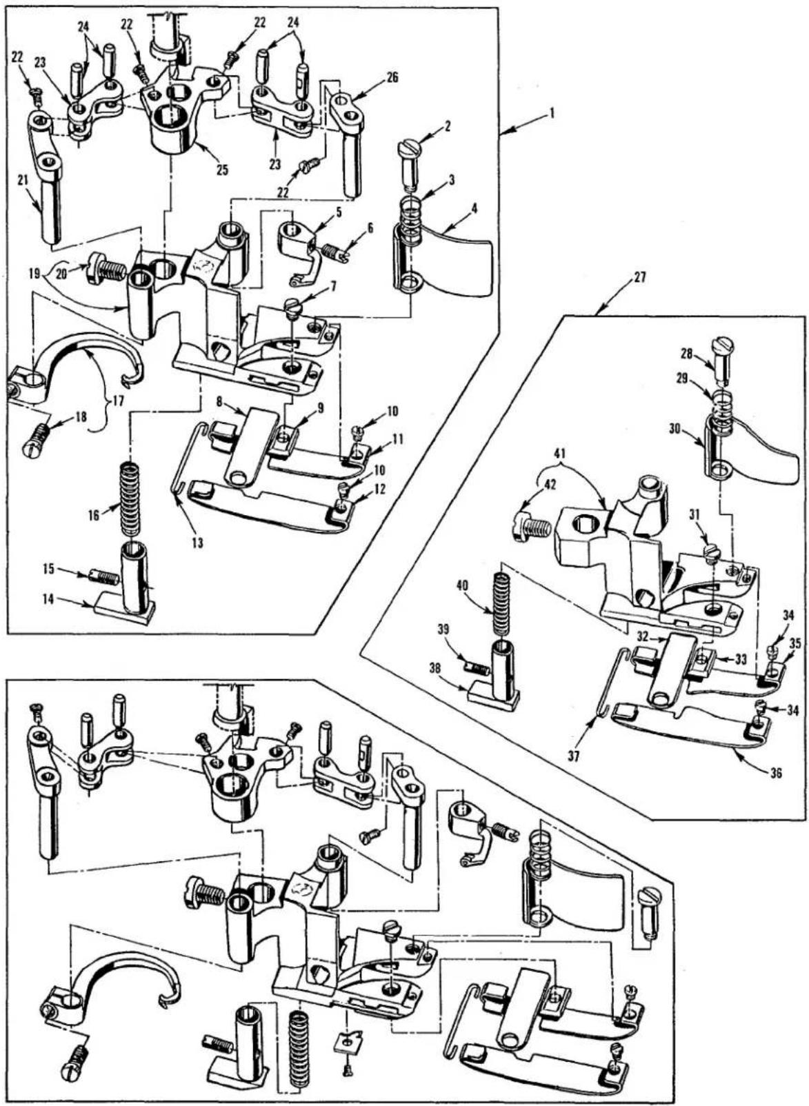
Technical diagram of mechanical assembly with numbered parts, likely a valve or clamp mechanism for assembly or maintenance.PRESSER FEET
| Ref. No. | Part No. | Description | Amt. Req. |
| 1. | 36220 A | Presser Foot, complete, for Styles 36200 PA, TA | 1 |
| - | 36220 K | Presser Foot, complete, for Styles 36200 PJ, TJ | 1 |
| - | 36220 L | Presser Foot, complete, for Style 36200 AK | 1 |
| 2. | 22731 | Screw, for chip guard | 1 |
| 3. | 36279 D | Spring, for chip guard | 1 |
| 4. | 36279 C | Chip Guard | 1 |
| 5. | 36251 E | Cover Thread Carrier, for 36220 A, L presser foot | 1 |
| - | 36251 W | Cover Thread Carrier, for 36220 K presser foot | 1 |
| 6. | 22565 A | Screw, cover thread carrier | 1 |
| 7. | 150 | Screw, for stationary knife clamp | 1 |
| 8. | 36250 | Stationary Knife | 1 |
| *9. | 36250 B | Stationary Knife Clamp, .213" (5.41mm) ID Mark"A" | 1 |
| *- | 36250 G | Stationary Knife Clamp, .222" (5.64mm) ID Mark "B" | 1 |
| *- | 36250 J | Stationary Knife Clamp, .226" (5.74mm) ID Mark "J" | 1 |
| 10. | 22738 G | Screw, for presser foot shoe | 2 |
| #11. | 36232 AH | Presser Foot Shoe, right, for 36220 A, K, L presser foot | 1 |
| #12. | 36231 AH | Presser Foot Shoe, left, for 36220 A, K, L presser foot | 1 |
| 13. | 36230 D | Shoe Holding Wire | 1 |
| 14. | 36230 J | Yielding Section, for 36220 A, K presser foot | 1 |
| - | 36230 P | Yielding Section, for 36220 L presser foot | 1 |
| 15. | 22565 A | Screw, for yielding section | 1 |
| 16. | 36230 C | Spring, for yielding section | 1 |
| 17. | 36251 F | Cross Thread Hook, for 36220 A, L presser foot | 1 |
| - | 36251 FA | Cross Thread Hook, for 36220 K presser foot | 1 |
| 18. | 22562 A | Screw, for cross thread hook | 1 |
| 19. | 36230 U | Presser Foot Base, for 36220 A, K, L presser foot | 1 |
| 20. | 94 | Screw, for presser foot base | 1 |
| 21. | 36251 H | Cover Thread Hook Driving Lever and Shaft | 1 |
| 22. | 22738 P | Screw | 4 |
| 23. | 36251 J | Link, for ref. no. 21, 25 and 26 | 2 |
| 24. | 36251 K | Link Pin | 4 |
| 25. | 36251 L | Cover Thread Carrier and Hook Driving Segment | 1 |
| 26. | 36251 G | Cover Thread Carrier Driving Lever and Shaft | 1 |
| 27. | 36220 B | Presser Foot, complete, for Styles 36200 PX, TX | 1 |
| 28. | 22731 | Screw, for chip guard | 1 |
| 29. | 36279 D | Spring, for chip guard | 1 |
| 30. | 36279 H | Chip Guard | 1 |
| 31. | 150 | Screw, for stationary knife clamp | 1 |
| 32. | 36250 | Stationary Knife | 1 |
| *33. | 36250 B | Stationary Knife Clamp, .213" (5.41mm) ID Mark"A" | 1 |
| *- | 36250 G | Stationary Knife Clamp, .222" (5.64mm) ID Mark "B" | 1 |
| *- | 36250 J | Stationary Knife Clamp, .226" (5.74mm) ID Mark “J" | 1 |
| 34. | 22738 G | Screw, for presser foot shoe | 2 |
| #35. | 36232 AL | Presser Foot Shoe, right, for 36220 B presser foot | 1 |
| #36. | 36231 AL | Presser Foot Shoe, left, for 36220 B presser foot | 1 |
| 37. | 36230 D | Shoe Holding Wire | 1 |
| 38. | 36230 J | Yielding Section | 1 |
| 39. | 22565 A | Screw, for yielding section | 1 |
| 40. | 36230 C | Spring, for yielding section | 1 |
| 41. | 36230 G | Presser Foot Base, for 36220 B presser foot | 1 |
| 42. | 94 | Screw, for presser foot base | 1 |
* When replacing the stationary knife clamp, order the clamp that has the same finish as the one being replaced.
See page 39 for other presser foot shoes available.
text_image
Technical diagram of mechanical assembly with numbered parts, likely a valve or clamp mechanismPRESSER FEET
| Ref. No. | Part No. | Description | Amt. Req. |
| 1. | 36220 H | Presser Foot, complete, for Styles 36200 PH, TH | 1 |
| - | 36220 M | Presser Foot, complete, for Styles 36200 PM, TM | 1 |
| 2. | 36279 D | Spring, for chip guard | 1 |
| 3. | 36279 C | Chip Guard | 1 |
| 4. | 22731 | Screw, for chip guard | 1 |
| 5. | 22738 G | Screw, for presser foot shoe | 2 |
| #6. | 36232 AM | Presser Foot Shoe, right, for Style 36220 H presser foot | 1 |
| #- | 36232 AP | Presser Foot Shoe, right, for Style 36220 M presser foot | 1 |
| #7. | 36231 AM | Presser Foot Shoe, left, for Style 36220 H presser foot | 1 |
| #- | 36231 AP | Presser Foot Shoe, left, for Style 36220 M presser foot | 1 |
| *8. | 36250 B | Stationary Knife Clamp, .213" (5.41mm) ID Mark"A" | 1 |
| *- | 36250 G | Stationary Knife Clamp, .222" (5.64mm) ID Mark "B" | 1 |
| *- | 36250J | Stationary Knife Clamp, .226" (5.74mm) ID Mark "J" | 1 |
| 9. | 36250 | Stationary Knife | 1 |
| 10. | 150 | Screw, for stationary knife clamp | 1 |
| 11. | 36230 D | Shoe Holding Wire | 1 |
| 12. | 36230 R | Cloth Guide Plate | 1 |
| 13. | 22716 A | Screw, for cloth guide plate | 1 |
| 14. | 36230 C | Spring, for yielding section | 1 |
| 15. | 36230 P | Yielding Section | 1 |
| 16. | 22565 A | Screw, for yielding section | 1 |
| 17. | 36251 F | Cross Thread Hook, for 36220 H presser foot | 1 |
| - | 36251 FA | Cross Thread Hook, for 36220 M presser foot | 1 |
| 18. | 22562 A | Screw, for cross thread hook | 1 |
| 19. | 36230 S | Presser Foot Base, for 36220 H presser foot | 1 |
| - | 36230 V | Presser Foot Base, for 36220 M presser foot | 1 |
| 20. | 94 | Screw, for presser foot base | 1 |
| 21. | 63251 H | Cover Thread Hook Driving Lever and Shaft | 1 |
| 22. | 22738 P | Screw | 4 |
| 23. | 36251 J | Link, for ref. no. 21, 25 and 26 | 2 |
| 24. | 36251 K | Link Pin | 4 |
| 25. | 36251 L | Cover Thread Carrier and Hook Driving Segment | 1 |
| 26. | 36251 G | Cover Thread Carrier Driving Lever and Shaft | 1 |
| 27. | 36251 E | Cover Thread Carrier, for Styles 36200 PH, TH | 1 |
| - | 36251 W | Cover Thread Carrier, for Styles 36200 PM, TM | 1 |
| 28. | 22565 A | Screw, for cover thread carrier | 1 |
* When replacing the stationary knife clamp, order the clamp that has the same finish as the one being replaced.
See page 39 for other presser foot shoes available.
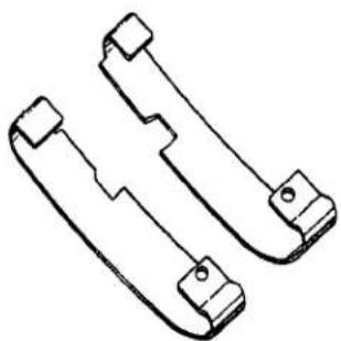
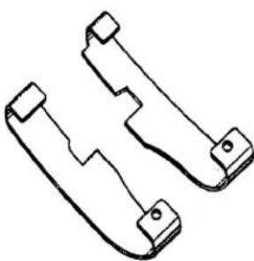
PRESSER FOOT SHOE CHART
| STANDARD PRESSER FEET | |
| 1 | 36220 |
| 2 | 36220A |
| 3 | 36220B |
| 4 | 36220E |
| 5 | 36220H |
| 6 | 36220J |
| 7 | 36220K |
| 8 | 36220L |
| 9 | 36220M |
| 10 | 36220V |
SELECTING PROPER PRESSER FOOT SHOES
THICKNESS OF SHOES
.014 THICK----Used when sewing lightweight material, when light presser foot pressure is essential. .020 THICK-- Used when sewing medium to heavyweight material, requiring more foot pressure.
WIDTH OF SHOES
NARROW SHOES--- Used for medium to heavier weight material WIDE SHOES---- Used for light weight material
LENGTH OF SHOE TOE
SHORT TOE----Furnished as standard on presser foot, because it adapts easily to a variety of operations and material. EXTENDED TOE -- Gives more feeding surface to the front of the presser foot, and may allow the operator to start the seam without raising the presser foot.
natural_image
Technical line drawing of two mechanical bracket components (no text or symbols)LONG SHOE
natural_image
Technical line drawing of two mechanical bracket components (no text or symbols)SHORT SHOE
| PRESSER FOOTSHOE | RIGHT | LEFT | MATERIAL THICKNESS | |
| .014 | .020 | |||
| 36231AD | X | X | ||
| 36232AD | X | X | ||
| 36231AE | X | X | ||
| 36232AE | X | X | ||
| 36231AF | X | X | ||
| 36232AF | X | X | ||
| 36231AG | X | X | ||
| 36232AG | X | X | ||
| 36231AH | X | X | ||
| 36232AH | X | X | ||
| 36231AJ | X | X | ||
| 36232AJ | X | X | ||
| 36231AK | X | X | ||
| 36232AK | X | X | ||
| 36231AL | X | X | ||
| 36232AL | X | X | ||
| 36231AM | X | X | ||
| 36232AM | X | X | ||
| 36231AP | X | X | ||
| 36232AP | X | X | ||
| 36231AW | X | X | ||
| 36232AW | X | X | ||
| 36231AY | X | X | ||
| 36232AY | X | X | ||
| 36231AZ | X | X | ||
| 36232AZ | X | X | ||
| 36231BA | X | X | ||
| 36232BA | X | X | ||
| 36231BB | X | X | ||
| 36232BB | X | X | ||
PRESSER FOOT SHOE CHART
| SHORT TOE | EXTENDED TOE | SHOE WIDTH | STANDARD ON PRESSER FOOT | CAN ALSO BE USED ON | FURNISHED ON MACH. STYLE | SAME AS |
| X | 3/8 | NONE | 1°2'3"6'7"8 | NONE | ||
| X | 11/32 | |||||
| X | 13/32 (9.5mm) | 2°3'7"8 | NONE | 36231BB | ||
| X | 3/8 (8.8mm) | 36232BB | ||||
| X | 13/32 (10.3mm) | NONE | 1°2'3"6'7"8 | NONE | ||
| X | 3/8 (9.5mm) | |||||
| X | 13/32 (10.3mm) | NONE | 1°2'3"6'7"8 | NONE | ||
| X | 3/8 (9.5mm) | |||||
| X | 11/32 (8.7mm) | 36220K | 1°3'6'8 | 36231AY | ||
| X | 11/32 (8.7mm) | 36232AY | ||||
| X | 11/32 (8.7mm) | NONE | 1°2'3"6'7"8 | 36200AK,PA,PJ, 3620TA,TJ,TL | ||
| X | 11/32 (8.7mm) | |||||
| X | 1/2 (12.7mm) | 36220V | 5°9 | 36200TL | 36231AW | |
| X | 9/32 (7.1mm) | 36220E | 36232AW | |||
| X | 13/32 (9.5mm) | 1°2'6'7"8 | 36231BA | |||
| X | 3/8 (9.5mm) | 36232BA | ||||
| X | 1/2 (12.7mm) | 36220H | 4°9'10 | 36200PH,36200TH | ||
| X | 5/16 (7.9mm) | |||||
| X | 1/2 (12.7mm) | 36220M | 4°5'10 | 36200PM,36200TM | ||
| X | 9/32 (7.1mm) | |||||
| X | X | 1/2 (12.7mm) | NONE | 1°2'3"6'7"8 | NONE | 36231AK |
| X | X | 9/32 (7.1mm) | 36232AK | |||
| X | 11/32 (8.7mm) | 36220A;36220K; 36220L | 1°2'3'6'7 | 36200AK;36200PA;TA 3620PJ,TJ | 36231AH | |
| X | 11/32 (8.7mm) | 36232AH | ||||
| X | 11/32 (8.7mm) | NONE | 1°2'3"6'7"8 | 36200AK | 36231AJ | |
| X | 11/32 (8.7mm) | 36200AK | 36232AJ | |||
| X | 13/32 (10.3mm) | 36220B | 1°2'5'7"8 | 36200PX,36200TX | 36231AL | |
| X | 3/8 (9.5.) | 36232AL | ||||
| X | 13/32 (10.3mm) | 36220,36220J | 2°3'7"8 | NONE | 36231AE | |
| X | 3/8 (9.5mm) | 36232AE |
text_image
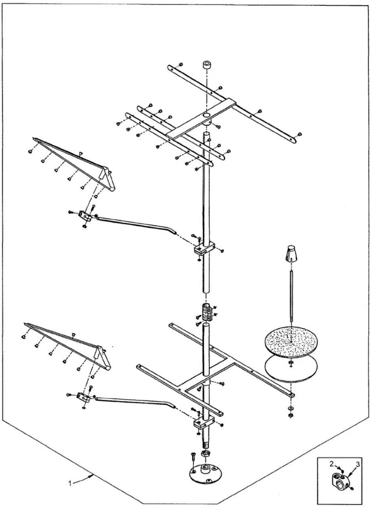
Technical diagram of a mechanical assembly with labeled components and directional arrows, including parts like fan, lever, and adjustment knobs.THREAD STAND
Ref.
No. Part No.
Description
Amt.
Req.
-
21101-S-7 Thread Stand, complete, for Styles 36200 AK, TA, TH, TJ, TM, TX.... 1
-
21233 AJ Bracket Connection, marked "AJ", for Style 36200 AK.... 1
- 21233 KS Bracket Connection, marked "KS", for Styles 36200 PA, PH, PJ, PM, PX ...... 1
- 22651 CD-5 Screw, for bracket connection (21233AJ) 4
- 22651 CD-5 Screw, for bracket connection (21233KS) 2

MISCELLANEOUS GAUGES & TAPE REEL PARTS
| Ref. | Amt. | ||
| No. | Part No. | Description | Req. |
| 1. | 21227 CN | Looper Travel Gauge, complete | 1 |
| 2. | 21227 CM | Looper Travel Gauge Pointer | 1 |
| 3. | 21227 CS | Looper Travel Gauge Plate | 1 |
| 4. | 21388 AZ | Wrench, for driving link stud | 1 |
| 5. | 21227 CU | Looper Alignment Gauge | 1 |
| 6. | 21227 BU | Needle Height Gauge, for all Styles except 36200 PJ, PM, TJ, TM | 1 |
| - | 21227 DS | Needle Height Gauge, for Styles 36200PJ, PM, TJ, TM | 1 |
| 7. | 21225 F-3/16 | Looper Gauge | 1 |
| 8. | 21388 Y | Spanner Wrench | 1 |
| 9. | 21227 CG | Synchronizing Gauge, for looper and needle timing, complete | 1 |
| 10. | 21227 CK | Synchronizing Gauge Rod | 1 |
| 11. | 21227 CJ | Looper Clamp and Height Gauge | 1 |
| 12. | 22738 | Screw | 1 |
| 13. | 22703 A | Screw | 1 |
| 14. | 21227 CH | Needle Setting Block | 1 |
| 15. | 14087 | Thumbscrew | 1 |
| 16. | 1347 A | Nut | 1 |
| 17. | TT85 | Wrench, for 3/16" square nut on screw | 1 |
| 18. | 21227 BV | Looper Avoid Gauge | 1 |
| 19. | 21227 CV | Cover Thread Hook Gauge | 1 |
| 20. | 23279 D | Folder Threader | 1 |
| 21. | 753 | Adjustable Axle Cone | 1 |
| 22. | 188 D | Screw, for adjustable axle cone | 1 |
| 23. | 51292 F-8 | Spring, for tape holder disc | 1 |
| 24. | 21178 | Tape Holder Disc | 2 |
| 25. | 88 | Screw, for collar | 1 |
| 26. | 161 | Collar | 1 |
| 27. | 21114 W | Tape Reel Axle | 1 |
| 28. | 258 A | Nut, for tape reel axle | 1 |
| 29. | 21171 Z | Tape Reel Frame | 1 |
| 30. | 22729 A | Screw, for tape reel frame | 2 |
| 31. | 21171 AA | Tape Guide | 1 |
| 32. | 23401 P-7/16 | Tape Folder | 1 |
| 33. | 357 | Screw, for tape folder | 2 |
| 34. | 28 | Screw, for tape guide | 1 |
| 35. | 36279 E | Frame Chip Guard | 1 |
| 36. | 22777 B | Screw, for Frame Chip Guard, for Styles 36200PX, TX | 1 |
| 37. | 36279 B | Spring, for Frame Chip Guard, for Styles 36200PX, TX | 1 |
| 38. | 36279 A | Washer, for Frame Chip Guard, for Styles 36200PX, TX | 1 |
| 39. | 21227 AR | Torque Rod, for Needle Head | 1 |
*Indicates tape holder parts for Styles 36200 PX, TX
text_image
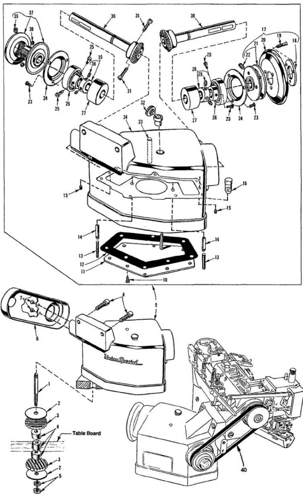
Technical diagram of a mechanical assembly with numbered parts and labeled components such as 'Table Board' and 'UnionSpecial'.DRIVE UNIT, BELT GUARD & TABLE MOUNTING PARTS
| Ref. | Amt. | ||
| No. | Part No. | Description | Req. |
| 1. | 35895 R | Mounting Stud | 3 |
| 2. | 21371 UE | Washer | 6 |
| 3. | 660-275 | Neoprene Isolator | 6 |
| 4. | 660-161 | Felt Isolator | 9 |
| 5. | 651 B-24 | Nut | 6 |
| 6. | 36295 J | Belt Guard | 1 |
| 7. | 25 S | Screw, for belt guard | 2 |
| 8. | 22652 F-20 | Screw | 2 |
| *9. | 29480 CK | Auxiliary Support and Drive, complete | 1 |
| 10. | 22569 C | Screw, for bottom cover | 8 |
| 11. | 36295 Z | Bottom Cover | 1 |
| 12. | 36295 AA | Gasket | 1 |
| 13. | 666-128 | Oil Wick | 2 |
| 14. | 36293 A | Oil Tube | 2 |
| 15. | 22571 A | Plug Screw | 2 |
| 16. | 51-120 BLK | Oil Gauge | 1 |
| 17. | 36295 H | Handwheel Assembly | 1 |
| 18. | 61321 L | Spacer Plate | 1 |
| 19. | 22574 | Screw | 3 |
| 20. | 61321 J | Handwheel | 1 |
| 21. | 36295 F | Pulley | 1 |
| 22. | 22894 V | Screw | 2 |
| 23. | 22569 C | Screw | 6 |
| 24. | 36295 AC | Ball Bearing Cap | 2 |
| 25. | 36295 AE | Screw | 4 |
| 26. | 660-302 | Ball Bearing | 2 |
| 27. | 36295 Y | Bushing | 2 |
| 28. | 21705 | Collar | 1 |
| 29. | 22894 C | Screw | 2 |
| 30. | 36295 W | Gear Shaft | 2 |
| 31. | 22882 A | Screw | 2 |
| 32. | 666-96 | Oil Filler Plug | 1 |
| 33. | 36295 AB | Gear Locating Pin | 1 |
| 34. | 36295 V | Machine Support | 1 |
| 35. | 21705 | Collar | 1 |
| 36. | 22894 C | Screw | 2 |
| 37. | 36295 G | Variable Speed Pulley | 1 |
| 38. | 22878 | Screw | 2 |
| 39. | 22650 AE-4 | Socket Set Screw | 1 |
| *- | 35829 AE | Auxiliary Support and Drive (not shown) | 1 |
| 40. | 21261M210 | Belt | 1 |
*These items available at extra send charge for Styles 36200 TA, TH, TJ, TM, TX.
NUMERICAL INDEX OF PARTS
| Part No. | Page No. | Part No. | Page No. | Part No. | Page No. | Part No. | Page No. | Part No. | Page No. |
| 109 | ......17 | 22569 | B ......9 | 22849 | ......29, 31 | 35847 | X ......15 | 36222 | C ......13 |
| 1096B | ......25, 27 | 22569 | C ......43 | 22878 | ......43 | 35850 | F ......31 | 36223 | ......13 |
| 12538 | ......19 | 22569 | D ......11 | 22881 | A ......19 | 35851 | L ......27 | 36223 | A ......13 |
| 12865 | ......27 | 22569G | ......25 | 22882 | A ......43 | 35851 | M ......23 | 36224 | H ......29 |
| 12934A | ......9, 25 | 22571 | A ......29, 43 | 22894 | AM .....13, 15 | 35851 | N ......23 | 36224 | K ......29 |
| 1347A | ......41 | 22571 | B ......13 | 22894 | C ......43 | 35859 | D ......19 | 36225 | ......21 |
| 14087 | ......41 | 22572 | B ......27 | 22894 | E ......15 | 35859 | J ......19 | 36226 | A ......21 |
| 150 | ......33, 35 | 22574 | ......43 | 22894 | J .....13, 19 | 35862 | A ......15 | 36226 | B ......21 |
| 15037 | A ......27 | 22578 | H ......21 | 22894 | K ......13 | 35866 | ......23 | 36226 | H ......21 |
| 161 | ......41 | 22580 | ......13 | 22894 | V ......43 | 35866 | A ......11 | 36226 | J ......21 |
| 18 | ......21, 23, 25, 27 | 22585 | ......25 | 22894 | W .....13, 15 | 35866 | B ......11 | 36229 | A-1 ......29 |
| 188 | D ......41 | 22585 | A .....13, 27 | 22894 | W .....21, 23 | 35876 | U ......29 | 36229 | B ......19 |
| 21101-S-7 | ......39 | 22585 | C .....17, 19 | 22894 | W ......31 | 35880 | M ......19 | 36230 | C ....33, 35 |
| 21114 | W ......41 | 22585 | C ......29 | 22894 | X ......25 | 35883 | AL ......11 | 36230 | D ....33, 35 |
| 21171 | AA ......41 | 22587 | B ......15 | 23279 | D ......41 | 35883 | G ......31 | 36230 | G ......33 |
| 21171 | Z ......41 | 22587 | E ......13, 21 | 23401 | P-7/16 ....41 | 35884 | M ......29 | 36230 | J ......33 |
| 21178 | ......41 | 22587 | E ......23 | 23420 | DB ......29 | 35884 | R ......31 | 36230 | P ....33, 35 |
| 21225 | F-3/16 ...41 | 22587 | H ......21 | 23423 | X ......29 | 35887 | AE ......9 | 36230 | R ......35 |
| 21227 | AR ......41 | 22596 | ......29, 31 | 23424 | Z ......29 | 35887 | AF ......11 | 36230 | S ......35 |
| 21227 | BU ......41 | 22596 | B ......15 | 25 S | ......43 | 35887 | AG ......9 | 36230 | U ......33 |
| 21227 | BV ......41 | 22650 | AE-4 ......43 | 255 | ......17 | 35887 | M ......9 | 36230 | V ......35 |
| 21227 | CG ......41 | 22651 | CD-5 ......39 | 258 | ......23 | 35887 | R ......9 | 36231 | AH ......33 |
| 21227 | CH ......41 | 22652 | A-6 ......27 | 258 A | ......17, 27 | 35887 | X ......9 | 36231 | AL ......33 |
| 21227 | CJ ......41 | 22652 | F-20 ......43 | 258 A | ......41 | 35887 | Z ......11 | 36231 | AM ......35 |
| 21227 | CK ......41 | 22653 | B-8 ......19 | 269 | ......21, 23 | 35888 | N ......9 | 36231 | AP ......35 |
| 21227 | CM ......41 | 22653 | E-24 ......29 | 269 | ......25, 27 | 35888 | T ......9 | 36232 | AH ......33 |
| 21227 | CN ......41 | 22703 | A ......41 | 28 | ......19, 41 | 35889 | H ......9 | 36232 | AL ......33 |
| 21227 | CS ......41 | 22711 | ......9 | 28 A | ......19 | 35890 | E ......11 | 36232 | AM ......35 |
| 21227 | CU ......41 | 22716 | A ......29, 35 | 28 C | ......11 | 35890 | P ......9 | 36232 | AP ......35 |
| 21227 | CV ......41 | 22729 | A ......41 | 29101 | J .....13, 23 | 35893 | G ......9 | 36234 | C ......21 |
| 21227 | DS ......41 | 22729 | C ......21, 23 | 29103 | T .....13, 21 | 35893 | H ......9 | 36234 | E ......21 |
| 21233 | AJ ......39 | 22729 | C ......25, 27 | 29105 | BH ......11 | 35894 | J ......13 | 36234 | F ......21 |
| 21233 | KS ......39 | 22729 | M ......25 | 29472 | AC ......13 | 35894 | L ......13 | 36234 | G ......21 |
| 21261M210 | ......43 | 22731 | ......33, 35 | 29472 | Y ......13 | 35895 | R ......43 | 36234 | M ......21 |
| 21371 | UE ......43 | 22733 | B ......11 | 29476XC | ......9 | 35895 | X ......13 | 36236 | ......23 |
| 21388 | AZ ......41 | 22733 | G ......23 | 29478 | CS ......21 | 35895 | Y .....13, 15 | 36236 | A ......23 |
| 21388 | Y ......41 | 22738 | ......41 | 29478 | CT ......23 | 35897 | BU ......13 | 36236 | B ......23 |
| 21705 | ......43 | 22738 | B ......29 | 29478 | CU ......27 | 35897 | BV ......13 | 36236 | C ......23 |
| 21756 | G ......13 | 22738 | C ......19 | 29478 | CZ ......31 | 35897 | BW ......13 | 36236 | E ......21 |
| 22 KH | ......9, 29 | 22738 | G .....33, 35 | 29478 | FF ......23 | 35897 | BY ......15 | 36236 | F ......21 |
| 22504 | C ......23 | 22738 | H ......19 | 29480 | CK ......43 | 35897 | CK ......19 | 36236 | G ......21 |
| 22513 | ......19 | 22738 | P .....33, 35 | 318 | ......19 | 36 G | ......25 | 36236 | H .....21, 23 |
| 22516 | A ......9 | 22747 | ......21, 27 | 33174 | B ......21 | 36203 | ......29 | 36236 | J ......23 |
| 22517 | ......17 | 22759 | A ......9 | 357 | ......41 | 36204 | ......9 | 36236 | K ......23 |
| 22519 | ......17 | 22766 | ......15, 31 | 35751 | G ......27 | 36204 | A ......9 | 36237 | ......23 |
| 22519 | F ......13 | 22767 | A ......25 | 35760 | D ......11 | 36205 | A ......21 | 36237 | A ......23 |
| 22524 | ......19 | 22768 | B ......11 | 35761 | D ......11 | 36205 | B ......21 | 36237 | E ......31 |
| 22528 | ......21 | 22777 | B .....19, 41 | 35763 | F ......15 | 36205 | H ......21 | 36237 | H ......31 |
| 22539 | AA ......9 | 22784 | F ......17 | 35763 | G ......15 | 36205 | J ......21 | 36237 | J ......31 |
| 22539 | AL ......31 | 22791 | D ......11 | 35766 | B ......23 | 36208 | A ......27 | 36237 | K ......31 |
| 22539 | M ......9 | 22791 | E ......31 | 35767 | ......19 | 36210 | ......27 | 36237 | L ......31 |
| 22539 | T ......11 | 22795 | B ......27 | 35781 | D ......11 | 36218 | ......19 | 36238 | ......31 |
| 22560 | A .....19, 31 | 22797 | ......15 | 35792 | ......17 | 36218 | J ......19 | 36238 | F ......31 |
| 22562 | A ......15 | 22798 | ......29 | 35792 T ......17 | 36220 A ......33 | 36240 | ......29 | ||
| 22562 | A .....17, 29 | 22799 | B ......11 | 35815 C ......15 | 36220 B ......33 | 36240 | J ......29 | ||
| 22562 | A .....33, 35 | 22799 N ......25 | 35817 E ......19 | 36220 H ......35 | 36244 | ......21 | |||
| 22564 | ......15 | 22801 ......13, 29 | 35829 AE ......43 | 36220 K ......33 | 36244 | A ......21 | |||
| 22564 | B .....9, 11 | 22829 ......11 | 35836 C ......23 | 36220 L ......33 | 36245 | B ......27 | |||
| 22564 | D ......27 | 22839 ......9 | 35842 J ......23 | 36220 M ......35 | 36248 | ......27 | |||
| 22565 | A .....13, 33 | 22839 D ......17 | 35846 ......23 | 36221 D ......15 | 36249 | ......27 | |||
| 22565 | A ......35 | 22845 M ......21 | 35846 B ......23 | 36222 A ......15 | 36249 | A ......31 | |||
NUMERICAL INDEX OF PARTS
| Part No. | Page No. | Part No. | Page No. | Part No. | Page No. | Part No. | Page No. |
| 36249 | B......27 | 36279 | A......41 | 36295 | W......43 | 660-275 | 43 |
| 36250 | ......33, 35 | 36279 | B......41 | 36295 | Y......43 | 660-302 | 43 |
| 36250 | B......33, 35 | 36279 | C......33, 35 | 36295 | Z......43 | 660-935 | 9 |
| 36250 | G......33, 35 | 36279 | D......33, 35 | 36296 | A......29 | 661-150 | 31 |
| 36250 | J......33 | 36279 | E......41 | 36296 | B......29 | 664 F-16 | 19 |
| 36250 | J......35 | 36279 | H......33 | 36297 | J......13 | 666-128 | 43 |
| 36251 | B......25 | 36279 | L......19 | 36297 | M......13 | 666-338 | 13 |
| 36251 | C......25 | 36279 | M......19 | 36298 | F......17 | 666-341 | 29 |
| 36251 | D......19 | 36279 | N......19 | 36298 | G......17 | 666-96 | 43 |
| 36251 | E......33, 35 | 36280 | A......17 | 39145 | A......27 | 667 D-16 | 29 |
| 36251 | F......33, 35 | 36280 | C......17 | 39592 | AK......17 | 73 A......9, 11, 29 | |
| 36251 | FA......33, 35 | 36280 | D......17 | 39593 | C......9 | 73 C......9 | |
| 36251 | G......33, 35 | 36280 | J......19 | 41071 | G......9, 13 | 753......41 | |
| 36251 | H......33 | 36280 | N......17 | 41255 | B......21, 27 | 77......15, 23, 27 | |
| 36251 | J......33, 35 | 36280 | S......17 | 43246 | ......23 | 8372 A......19 | |
| 36251 | K......29, 33 | 36280 | T......17 | 4761 | ......25, 27 | 86......17 | |
| 36251 | K......35 | 36280 | U......17 | 51-120 | BLK......43 | 87 A......31 | |
| 36251 | L......33, 35 | 36280 | V......17 | 51054 | A......15 | 87 U......21 | |
| 36251 | M......15 | 36280 | W......17 | 51254 | K......15 | 88......27, 41 | |
| 36251 | N......15 | 36282 | ......31 | 51259 | ......19 | 90......9, 13 | |
| 36251 | P......25 | 36283 | B......29 | 51292 | F-2......17 | 93......9 | |
| 36251 | V......25 | 36283 | C......29 | 51292 | F-4......17 | 93 A......9 | |
| 36251 | W......33, 35 | 36283 | E......29 | 51292 | F-5......17 | 94......17, 33, 35 | |
| 36253 | A......27 | 36283 | F......29 | 51292 | F-8......41 | 97 A......25, 27 | |
| 36253 | B......27 | 36283 | G......29 | 52336 | ......27 | 98 A......29 | |
| 36253 | G......27 | 36283 | H......29 | 52841 | H......25 | 999-196......31 | |
| 36256 | ......9 | 36283 | J......29 | 52848 | B......25 | B3530555000......9 | |
| 36256 | A......9 | 36283 | K......31 | 52848 | C......25 | C36224 A......29 | |
| 36256 | B......31 | 36284 | ......29 | 52958 | C......9 | C36224 J......29 | |
| 36260 | ......11 | 36284 | C......31 | 52958 | F......9 | C50092 S......17 | |
| 36261 | ......25 | 36284 | E......29 | 531 | ......29, 31 | CL21......9, 11 | |
| 36261 | A......13 | 36284 | F......31 | 53636 | C......27 | J87 J......31 | |
| 36263 | ......15 | 36286 | ......31 | 538 | ......31 | LA528......9 | |
| 36264 | B......19 | 36286 | B......31 | 56354 | D......15 | SS7110510SP......11 | |
| 36264 | D......15 | 36289 | ......19 | 56390 | E......9 | TT85......41 | |
| 36264 | E......19 | 36289 | A......19 | 56392 | F......17 | WO3......19 | |
| 36264 | F......19 | 36289 | B......19 | 60078 | Z......31 | ||
| 36270 | B......25 | 36289 | H......19 | 604 | ......27 | ||
| 36271 | ......11 | 36289 | J......19 | 6042 | A......9, 19 | ||
| 36271 | A......11 | 36290 | A......11 | 6042 | A......23 | ||
| 36271 | E......11 | 36290 | B......11 | 605 | A......25 | ||
| 36271 | G......11 | 36290 | D......9 | 61321 | J......43 | ||
| 36271 | H......11 | 36292 | K......17 | 61321 | L......43 | ||
| 36273 | A......25 | 36292 | M......17 | 62238 | A......21, 23 | ||
| 36273 | C......25 | 36292 | N......17 | 62271 | B......11 | ||
| 36273 | D......25 | 36292 | P......17 | 63251 | H......35 | ||
| 36273 | F......25 | 36293 | A......43 | 651 | B-24......43 | ||
| 36273 | G......25 | 36293 | B......9 | 660-1115 | 31 | ||
| 36273 | J......25 | 36293 | E......9 | 660-1117 | 31 | ||
| 36273 | K......25 | 36293 | G......31 | 660-161 | 43 | ||
| 36273 | M......25 | 36294 | B......19 | 660-202 | 15, 25 | ||
| 36273 | N......25 | 36294 | C......19 | 660-206 | 11 | ||
| 36278 | ......19 | 36295 | AA......43 | 660-207 | 13, 23 | ||
| 36278 | A......19 | 36295 | AB......43 | 660-212 | 9 | ||
| 36278 | C......27 | 36295 | AC......43 | 660-215 | 27 | ||
| 36278 | F......19 | 36295 | AE......43 | 660-219 | D......25 | ||
| 36278 | H......19, 25 | 36295 | F......43 | 660-219 | P......13 | ||
| 36278 | J......25 | 36295 | G......43 | 660-220 | 21, 31 | ||
| 36278 | K......19 | 36295 | H......43 | 660-221 | 27 | ||
| 36278 | L......19 | 36295 | J......43 | 660-254 | C......17 | ||
| 36278 | M......19 | 36295 | V......43 | 660-261 | 19 | ||
NOTES
NOTES
Union Special Corporation
Corporate Office
One Union Special Plaza
Huntley, IL 60142
Phone: 847·669·5101
Fax: 847·669·4454
Union Special GmbH
EuropeanDistributionCenter
Raiffeisenstrasse 3
D-71696 Möglingen, Germany
Tel: 49·07141·247·0
Fax: 49·07141·247·100
JUKI CORPORATION
INTERNATIONAL SALES DIVISION
8-2-1, KOKURYO - CHO,