39500RG - Sewing machine Union Special - Free user manual and instructions
Find the device manual for free 39500RG Union Special in PDF.

User questions about 39500RG Union Special
0 question about this device. Answer the ones you know or ask your own.
Ask a new question about this device
Download the instructions for your Sewing machine in PDF format for free! Find your manual 39500RG - Union Special and take your electronic device back in hand. On this page are published all the documents necessary for the use of your device. 39500RG by Union Special.
USER MANUAL 39500RG Union Special
Union Special® INDUSTRIAL SEWING EQUIPMENT
CATALOG NO. 103QW
STYLES
39500QW 39500RG 39500RH
CLASS 39500
MARKIV HIGH SPEED
TWO NEEDLE FOUR THREAD
DIFFERENTIAL FEED
OVERSEAMING
SEAMING AND HEMMING MACHINES

text_image
Scanned text of contract clauses with partial company name and dateCatalog No. 103 QW (Supplement to Catalog No. 103 QA)
INSTRUCTIONS
FOR
ADJUSTING AND OPERATING
LIST OF PARTS
CLASS 39500
Styles
39500 QW
39500 RG
39500 RH
First Edition
Copyright © 1973
by
Union Special Corporation
Rights Reserved in All Countries
INDUSTRIAL SEWING MACHINES
CHICAGO
Printed in U.S.A.
May, 1981
IDENTIFICATION OF MACHINES
Each UNION SPECIAL machine is identified by a Style number on a name plate on the machine. Style numbers are classified as standard and special. Standard Style numbers have one or more letters suffixed, but never contain the letter "Z". Example: "Style 39500 QW". Special Style numbers contain the letter "Z". When only minor changes are made in a standard machine, a "Z" is suffixed to the standard Style number. Example: "Style 39500 QWZ".
Styles of machines similar in construction are grouped under a Class number which differs from the Style number in that it contains no letters. Example: "Class 39500".
APPLICATION OF CATALOG
This catalog is a supplement to Catalog No. 103 QA and should be used in conjunction therewith. Only those parts used on Styles 39500 QW, RG and RH, but not on Style 39500 QP are illustrated and listed at the back of this catalog. On the page opposite the illustration will be found a listing of the parts with their part numbers, description and the number of pieces required. Numbers in the first column are reference numbers only, and merely indicate the position of that part in the illustration. Reference numbers should never be used in ordering parts. Always use the part number listed in the second column.
This catalog applies specifically to the standard Styles of machines as listed herein. It can also be applied with discretion to some Special Styles of machines in Class 39500. References to directions, such as right, left, front, back, etc., are given from the operator's position while seated at the machine. Operating direction of handwheel is away from operator.
STYLES OF MACHINES
MARK IV Hi-Styled High Speed, Two Curved Blade Needles, Two Loopers, Four Thread Overseaming Machines. Differential Feed, Trimming Mechanism with Spring Pressed Lower Knife, Automatic Lubricating System, Improved Air Cooling System.
39500 QW Medium to heavy duty machine for seaming medium to heavy weight knitted and woven fabrics with a modified safety stitch. For operations on pajamas, bathing suits, house dresses, children's wear, ladies' undergarments and similar garments of light to medium heavy weight woven and knitted garments of wool, cotton, silk and synthetics. Seam specification 512-SSa-1. Standard width of seam from left needle 17/64 inch (6.75 mm). Stitch range, 8-20 per inch. Cam adjusted main and differential feeds. Maximum recommended speed 7500 R.P.M.
39500 RG Medium to heavy duty machine for decorative hemming of medium weight baby blankets and for similar operations on articles of medium weight woven materials. Hem is turned up with the roll extending to the right needle. Adjustable turned up hemming scroll on right side of presser foot. Seam specification 514-EFe-1. Standard seam width from left needle approximately 17/64 inch (6.75 mm). Stitch range, 6-15 per inch. Cam adjusted main and differential feeds. Maximum recommended speed 7000 R.P.M.
39500 RH Medium to heavy duty machine for seaming operations on coat linings, pockets, bathing suits, house dresses, children's wear, ladies undergarments, and similar garments of light to medium weight woven and knitted materials of cotton, wool, silk and synthetics. Seam specification 514-SSa-1. Standard seam width from left needle approximately 17/64 inch (6.75 mm). Stitch range, 6-15 per inch. Cam adjusted main and differential feeds. Maximum recommended speed 7500 R.P.M.
NOTE: On Styles 39500 RG and RH, the upper looper thread is caught by both needles.
SPEED RECOMMENDATION
39500 MARK IV machines have been tested in their complete stitch range at their maximum rated speeds. Varied field conditions, severity and cleanliness of the sewing operation may necessitate operating at a lower speed. When operating from 50-100% machine running cycle and a longer than recommended stitch length, it may be necessary to reduce the machine's speed by 10-15%.
The MARK IV is a precision manufactured and tested sewing machine. To obtain maximum performance, the machine should be operated at 1000 R.P.M. below maximum recommended speed for the first 20 days of field operation. This will minimize readjustment of precision mechanisms.
OILING
CAUTION! Oil was drained from machine when shipped, so reservoir must be filled before beginning to operate. Oil capacity of Class 39500 is eight ounces. A straight mineral oil of Saybolt viscosity of 90 to 125 seconds at 100^ Fahrenheit should be used.
Machine is filled with oil at spring cap in top cover. Oil level is checked at sight gauge on front of machine. Red bulb on oil level indicator should show between gauge lines when machine is stationary.
Machine is automatically lubricated. No oiling is necessary, other than keeping main reservoir filled. Check oil daily before the morning start; add oil as required.
To maintain maximum recommended speed and serviceability of this equipment when operating continuously, the oil must be changed at least every six months. In no case should oil remain in machine for more than one year.
The oil drain plug screw is located at back of machine near bottom edge of base. It is a magnetic screw designed to accumulate possible foreign materials which may have entered the crank case. It should be removed and cleaned periodically.
NEEDLES
Each needle has both a type and size number. The type number denotes the kind of shank, point, length, groove, finish and other details. The size number, stamped on the needle shank, denotes largest diameter of blade, measured midway between shank and eye. Collectively, type and size number represent the complete symbol which is given on the label of all needles packaged and sold by Union Special.
Class 39500 machines use a curved blade needle. The standard recommended needle for the machines covered in this catalog is Type 154 GAS. Below is the description and sizes available of the recommended needle.
Type No.
Description and Sizes
154 GAS
Round shank, round point, curved blade, standard length, single groove, struck groove, spotted, chromium plated and is available in sizes 055/022, 065/025, 070/027, 075/029, 080/032, 090/036, 100/040, 110/044, 125/049, 140/054, 150/060.
To have needle orders promptly and accurately filled, an empty package, a sample needle, or the type and size number should be forwarded. Use description on label. A complete order would read: "1000 Needles, Type 154 GAS, Size 090/036".
NEEDLES (Continued)
Selection of proper needle size is determined by size of thread used. Thread should pass freely through needle eye in order to produce a good stitch formation.
CHANGING NEEDLES
Release pressure on presser foot by turning presser foot release bushing (AG, Fig. 1) and swing presser arm (U) out of position. Turn handwheel in operating direction until needles are at their lowest point of travel. Using hexagonal socket wrench No. 21388 AU, furnished with machine, loosen needle clamp nut about 1/4 turn. Again turn handwheel until needles are at their highest position. Withdraw needles.
To replace needles, leave needle holder at high position and with the flats to the left, insert needles in holder until they rest against stop pin. Keeping needles in this position, turn handwheel until holder is again at its low point of travel; then tighten nut. Return presser arm (U) to position; re-lock presser foot release bushing (AG).
THREAD STAND
After thread comes from cones on cone support (A, Fig. 1), the needle threads are threaded through the back bar of the thread eyelet (B), under the middle bar and through the center holes of the front bar. The looper threads come from the cones, through holes of the middle bar from back to front and then through the two outside holes of the front bar. Next it is threaded through the upper holes of tension thread guide (C) front to back and then through the lower holes from back to front. The threads continue between tension discs (J), through tension post slot (K) in tension post (G) and on through front thread guide (M).
THREADING
Only parts involved in threading are shown in the threading diagram (Fig. 1). Parts are placed in their relative positions for clarity.
It will simplify the threading of these machines to follow the recommended sequence of threading lower looper first, upper looper second, and the needles third.
Before beginning to thread, swing cloth plate open, turn handwheel in operating direction until needles (X) are in high position, release pressure on presser foot by turning presser foot release bushing (AG), and swing presser arm (U) out of position.
Be sure the threads, as they come from the tension thread guide (C), are between the tension discs (J) and in tension post slot (K) in tension post (G). The tension posts should be positioned so the tension post slot will be at the approximate angle for the different threads as indicated in Fig. 1.
TO THREAD LOWER LOOPER
Double end of thread and lead it through both eyes of lower looper thread eyelet (R, Fig. 1) from right to left. NOTE: Thread must pass in front of looper thread pull-off (AF). Lead thread behind fabric guard (S) and through eyelet hole of frame looper thread guide (T). Turn handwheel in operating direction until heel of lower looper (V) is all the way to the left; then thread through both eyes from left to right. Left eye of lower looper can be threaded easily if tweezers are in left hand.
TO THREAD UPPER LOOPER
Turn handwheel until point of upper looper (W) is all the way left. Lead thread through auxiliary looper thread eyelet (P) from back to front, then through both eyes of upper looper thread eyelet (N) from left to right. NOTE: Thread must pass in front of looper thread pull-off (AF). After pulling up upper looper thread tube assembly (AA), lead thread under neck of top cover casting and down through thread tube assembly (AA). Pull thread out bottom of tube; push tube down, then insert thread through upper looper eye from front to back.
CAUTION! Be sure upper looper thread is under lower looper thread when passing from tube assembly to upper looper eye.
TO THREAD THE NEEDLES
Turn handwheel in operating direction until needles (X, Fig. 1) are at their highest position. Insert both needle threads from right to left, through both eyes of needle thread eyelet (AD), under neck of top cover casting; and down through holes in top cover needle thread eyelet (AC). The right needle thread should be threaded through the right hole and the left needle thread through the left hole of the top cover needle thread eyelet. Thread needles from the front.

text_image
D Tension Nut E Tension Spring Ferrule F Tension Spring G Tension Post H Spring Shield J Tension Discs K Tension Post Slot L Tension Disc Felt B Thread Eyelet To Upper Looper To Left Needle To Right Needle A Cone Support 65° 45° 35° 30° C Tension Thread Guide M Front Thread Guide N Upper Looper Thread Eyelet P Auxiliary Looper Thread Eyelet R Lower Looper Thread Eyelet S Fabric Guard Bracket T Frame Looper Thread Guide U Presser Arm FOR STYLES 39500 QW, RG and RH AG Presser Foot Release Bushing AF Looper Thread Pull-off AE Needle Thread Cam Pull-off AD Needle Thread Eyelet AC Top Cover Needle Thread Eyelet AA Upper Looper Thread Tube Assembly X Needles W Upper Looper V Lower Looper Fig. 1THREAD TENSION
The amount of tension on the needle and looper threads is regulated by knurled tension nuts (D, Fig. 1). Tension on threads should be only enough to secure proper stitch formation.
PRESSER FOOT PRESSURE
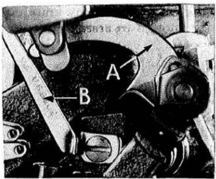
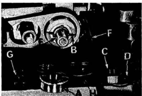
Sufficient presser foot pressure to feed work uniformly should be maintained. Should it be necessary to increase or decrease amount of pressure on presser foot, loosen lock nut (A, Fig. 2) and turn adjusting screw (B). Adjusting screw has a right hand thread so tightening increases pressure, loosening decreases pressure. When pressure adjusting screw (B) has been properly set, tighten lock nut (A). With presser foot resting on throat plate, position locking nut (C) so that its under surface is approximately 1/32 to 1/16 inch (.79 to 1.59 mm) from the top surface of adjusting screw (B). Set cap (D) against locking nut (C).

text_image
Labeled diagram of a mechanical device with components A, B, C, D and directional arrows indicating assembly or movement.Fig. 2
FEED ECCENTRICS
Feed eccentrics used in machine Styles 39500 QW and RH have been selected to produce approximately 10 stitches per inch. On machine Style 39500 RG, the feed eccentrics have been selected to produce approximately 8 stitches per inch. It will be noted that on Styles 39500 QW and RH, the part number of the main feed eccentric is No. 39540 B-12, while the part number of the differential feed eccentric is No. 39540 B-10. On Style 39500 RG, the part number of both the main and differential feed eccentric is No. 39540 B-8. Minor numbers of the part symbol indicate approximately the number of stitches obtainable when using that eccentric. Unless otherwise specified, machines will be shipped with the above combination of eccentrics.
Generally speaking, differential (right hand) feed eccentric determines number of stitches produced. Main (left hand) feed eccentric is selected in relation to degree and direction of stretch of material being sewn, or type of operation.
Following stitch number feed eccentrics are available under No. 39540 B-4, -5, -6, -7, -8, -9, -10, -11, -12, -13, -14, -15, -16, -18, -20, -22, -24, -26, -28, -30, -32, -34, -36, -40, -50, -60, -70, -100. Only two eccentrics are supplied with each machine. Additional eccentrics may be ordered separately. To order, use No. 39540 B with a minor number suffixed to indicate number of stitches desired. Example: "39540 B-10".
text_image
A B→ (12.30 MM) 3/7 64Fig. 3
ASSEMBLING AND ADJUSTING SEWING PARTS
Before assembling and adjusting sewing parts, remove cloth plate, fabric guard, chip guard, upper knife assembly, lower knife holder assembly. Then follow this suggested sequence:
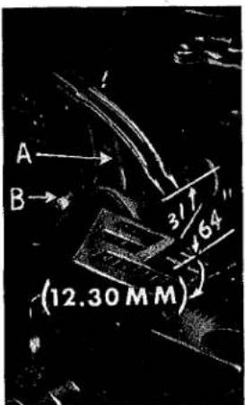
SETTING THE NEEDLES
With throat plate assembled in position, needles should center in the front end of needle slots. When needles are at high position, needle points should be set 31/64 inch (12.30 mm) above throat plate (Fig. 3). To align needles or set the height above the throat plate, move needle driving arm (A, Fig. 3) by loosening clamp screw (B). Remove throat plate, after needles have been set properly and clamp screw (B) has been tightened.
SETTING THE NEEDLES (Continued)
text_image
A BFig. 4
If needle thread cam pull-off (A, Fig. 4) overlaps looper thread pull-off (B), separate by moving looper thread pull-off back. When retightening looper pull-off screw, be sure to take up end play in needle driving arm.
At this point, insert lower looper (A, Fig. 5) into bar (B). With the lower looper at the left end of its stroke, set looper point 1/16 inch (1.59 mm) from center of left needle (Fig. 5), using looper gauge No. 21225-1/16. Do not have lower looper deflecting needle. Tighten nut (C).
Now assemble differential (front) feed dog.
SETTING THE REAR NEEDLE GUARD
Set rear needle guard (A, Fig. 6) as high as possible, without interfering with either lower looper or movement of lower knife holder, but still in position to deflect needles forward .002-.004 inch (.051-.102 mm). Screw (B) is used to set rear needle guard. Make sure there is no interference between rear needle guard and lower looper.

text_image
1/16 (1.59 MM) A C BFig. 5
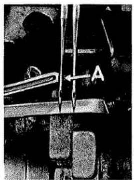
SETTING THE LOWER LOOPER
Now, finish lower looper adjustment. As lower looper moves to the right, its point should be set into the scarf of the left needle (A, Fig. 7) until the needles
spring forward from rear guard surface another .002-.004 inch (.051-.102 mm).
text_image
A C B DFig. 6
SETTING THE FRONT NEEDLE GUARD
Assemble front needle guard (C, Fig. 6). When lower looper is springing needles off rear needle guard, set front needle guard as close as possible to needles without touching. Screw (D) is used to adjust and set front needle guard. After this setting, make sure there is no interference between needle guards and differential feed dog.
text_image
AFig. 7
SETTING THE UPPER LOOPER
Insert upper looper (A, Fig. 8) in its holder. Screw (B) holds the upper looper in its holder and permits it to be pushed in or out, or turned around its shank. Insert upper
looper holder into upper looper shaft, if it is not already in place. Screw (C, Fig. 8) in clamp holds the upper looper holder in the shaft. Locate upper looper in its holder so that the shank extends 1/8 inch (3.17 mm) beyond holder (Fig. 8), for Styles 39500 RG and RH; 1/16 to 3/32 inch (1.59 to 2.38 mm) for Style 39500 QW.
SETTING THE UPPER LOOPER (Continued)
When the upper looper is at the right end of its stroke, upper looper holder should be set to position upper looper shank slightly back of vertical (Fig. 8).
Be sure there is a clearance between heel of looper and casting. By adjusting looper holder in or out of upper looper shaft and by turning the looper around its shank, set upper looper point to cross lower looper to the left of the lower looper eye with .002 to .004 inch (.051 to .102 mm) clearance (Fig. 9).
Next, turn the handwheel until the upper looper is at the left end of its travel. On Style 39500 QW, check dimensions of upper looper point with respect to the RIGHT needle and throat plate (Fig. 10). Looper point should be 9/64 inch (3.57 mm) to the left of centerline of RIGHT needle and 17/32 inch (13.49 mm) above throat plate (Fig. 10). On Styles 39500 RG and RH, check dimensions of upper looper point with respect to the LEFT needle and throat plate. Looper point should be 3/16 inch (4.76 mm) to the left of centerline of LEFT needle and 39/64 inch (15.48 mm) above throat plate. If resetting is necessary, do it by moving the upper looper holder (A, Fig. 10). NOTE: Figure 10 represents the correct dimensional settings for Style 39500 QW only.

text_image
.002" CLEARANCE (.051 MM)Fig. 9
Dimension 17/32 inch (13.49 mm) or 39/64 inch (15.48 mm) is increased by turning upper looper holder counterclockwise looking from left end of machine. Dimension 9/64 inch (3.57 mm) or 3/16 inch (4.76 mm) is increased by pulling upper looper holder to the left, out of the upper looper shaft. After these changes are made, it may be necessary to turn the upper looper around its shank slightly to maintain the condition shown in Fig. 9.

text_image
3.17 M.M C 3 1" 8 B A BACK OF VERTICALFig. 8

text_image
9" 64 (3.57MM) A 17 32 (13 49 MM)Fig. 10
Check setting to avoid interference between upper looper and needle on needle downstroke. If needle rubs the back of upper looper, pull looper out of its holder slightly and rotate looper a short distance counterclockwise, looking from left end of machine. Reset to maintain machine dimensions specified relative to Figs. 9 and 10.

text_image
NOTE POSITIONFig. 11
On Style 39500 QW only, a quick check of correct settings can be noted as follows: As upper looper is moving to the right and the upper looper eye centers on the RIGHT needle, the eyes of the upper looper and needle should align exactly (Fig. 11).
SETTING THE FEED DOGS
Assemble the main and differential feed dogs (A, B, Fig. 12). Main and differential feed dogs should be leveled with respect to the throat plate by rotating feed tilting adjusting pin (C). This pin raises or lowers the back end of feed bar.
The feed dogs should be set level at the time the teeth first appear above the throat plate. Screw (D, Fig. 12) locks feed
SETTING THE FEED DOGS (Continued)
tilting adjusting pin in place. With the feed dogs at their highest point of travel, the top of the teeth on the main and differential feed dogs (A, B) should be 3/64 inch (1.19 mm) above the throat plate. The chaining feed dog is made as an integral part of the main feed dog.

text_image
A B CFig. 12
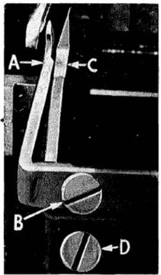
SETTING THE LOWER KNIFE
Replace lower knife holder assembly. Lower knife (A, Fig. 13) should be set with cutting edge flush with throat plate surface. Adjustments are made with hexagonal head screw which holds lower knife. Lower knife is spring pressed against upper knife, so no lateral adjustment is necessary when width of trim is changed.
Lower knife may be secured in any position by tightening screw (B) and locking nut (C) against support bracket. Because screw (B) also serves as latch pin for the cloth plate latch spring, it should always be locked with nut (C) even when screw is not tightened against lower knife holder.
SETTING THE UPPER KNIFE
Replace upper knife assembly. Clamp upper knife (D, Fig. 13) in position, setting nut (E) to hold clamp (F) in its most clockwise position against upper knife. Upper knife chain guard (J) should be positioned so that the guarding section is approximately 1/64 inch (.40 mm) behind the cutting edge and in contact with the top surface of the upper knife.
At the bottom of its stroke, front cutting edge of upper knife should extend not less than 1/64 inch (.40 mm) below the cutting edge of lower knife.
After upper knife has been set for the proper width of trim, screw (G) must be tightened to lock the upper knife holding block (H) in place. This will simplify resetting when upper knife is replaced.

text_image
H G O E J F D A C BFig. 13
SETTING THE STITCH LENGTH

text_image
A B C D E FFig. 14
Length of stitch is determined by the combination of feed eccentrics used. Outer (left) eccentric (A, Fig. 14) actuates main (rear) feed dog; while the inner (right) eccentric (B) actuates the differential (front) feed dog.
text_image
G B C D FFig. 15
SETTING THE STITCH LENGTH (Continued)
In assembling the feed eccentrics, be sure hubs are facing each other. Be careful not to damage shaft or key. Tighten nut (C) securely.
To change feed eccentrics, remove nut (C) and washer (D) from end of shaft (E). Turn handwheel in operating direction until key slot in eccentric is toward the front. Using hooked eccentric extractor (F), supplied with machine, reach behind eccentrics as shown and withdraw eccentrics. It may be necessary to move handwheel back and forth slightly during extraction.
If eccentrics are unusually tight fitting, in addition to removing nut (C) and washer (D, Fig. 15) from shaft (E), it may be helpful to remove nut (G) and feed driving connection (H). Then continue as originally suggested.
SETTING THE PRESSER FOOT
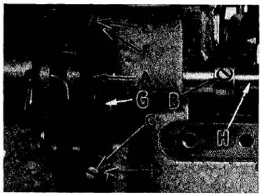
Assemble the presser foot to presser arm. With needles in high position, swing presser arm (U, Fig. 1) into sewing position and set the presser foot to align needle holes (front and back) and flat on throat plate. The front edge of needle hole in presser foot must be aligned with front edge of needle hole in throat plate. It is also important that the bottom of the presser foot be flat on the throat plate. If necessary, presser foot can be realigned with throat plate slots by shifting the foot lifter lever shaft (H, Fig. 16). To move the shaft, loosen collar screws (B, Fig. 16) and clamp screw (G) and then shift the foot lifter lever shaft to the left or right as required. Retighten collar screws and clamp screw.
The foot lifter lever arm (A, Fig. 16) and the collar (B) secure the shaft. Be sure the presser arm does not bind and rise when presser foot release bushing is unlocked. To center presser foot and stitch tongue with respect to throat plate needle hole, loosen presser foot hinge screw.
text_image
Technical diagram of a tank with labeled components and directional arrows indicating movement or flowFig. 16
Adjust lifter lever stop screw (C) so that presser foot can be raised no higher than upper looper will permit; then lock the nut (D). To find this maximum safe position, turn the handwheel so point of upper looper is directly over presser foot tongue. Raise presser foot by depressing the presser foot treadle and manually lower the toe of presser foot. Height adjustment is correct if presser foot tongue does not contact the upper looper. There should be from 1/16 to 1/8 inch (1.59 to 3.17 mm) free motion of foot lifter lever before the presser foot begins to rise. This adjustment is made with screw (E) and locked with nut (F).
Re-assemble chip guard, fabric guard and cloth plate. To make assembly of chip guard easy, turn handwheel until upper knife assembly reaches its highest position.
STARTING TO OPERATE
Be sure machine is threaded according to threading diagram (Fig. 1). With thread tensions light, set looper thread eyelets (N and R, Fig. 1) about horizontal and in the middle of their front to back locations. Operate machine slowly, without presser foot in place, to make sure that chain forms and moves off the tongue freely. Swing presser foot into position, insert material, and sew slowly.
NEEDLE THREAD CONTROL
While sewing on material, check needle thread control as follows: Usually all needle thread is drawn on needle down stroke. At top of needle stroke, thread should be just tight enough to feed chain off stitch tongue. Stitch tends to pull down slightly if excessive thread is pulled on the up stroke. With needle at bottom of stroke, position needle thread eyelet (AD, Fig. 1) so that needle cam pull-off (AE) just contacts needle thread.
LOWER LOOPER THREAD CONTROL
With material under presser foot, set lower looper thread eyelet (R, Fig. 1) back far enough so thread is a little slack when looper thread pull-off (AF) reaches its most rearward position. Looper thread pull-off (AF) is set about 1/8 inch (3.17 mm) distance behind needle thread cam pull-off (AE). Frame looper thread guide (T) should be set with its eyelet approximately 1/8 inch (3.17 mm) to the right of lower looper (V) heel eyelet at the time lower looper is at extreme left end of its travel.
While sewing on material, check drawing off of looper thread as follows: A portion of lower looper thread should be drawn through the tension before lower looper thread comes off upper looper. To increase amount of thread drawn through the tension while lower looper thread is on upper looper, move lower looper thread eyelet (R) down, keeping the same amount of pull-off action.
UPPER LOOPER THREAD CONTROL
Before proceeding to adjust upper looper thread eyelet (N, Fig. 1) balance all four tensions to give a normal appearing stitch. Moderate change in these tensions will not markedly affect the purl.
During needle down stroke, forward stroke of looper thread pull-off (AF) will draw upper looper thread through the tension. When normal amount of looper thread is drawn, upper looper thread will have almost all slack taken up as looper thread pull-off reaches its most rearward position.
POSITIONING THE PURL
To move the purl more under the edge, both looper thread eyelets (N and R, Fig. 1) should be raised keeping the same amount of pull-off. Usually it is better to have slightly more pull-off on upper thread than on lower thread.
If it becomes necessary to move looper thread pull-off (AF), be sure to take up all end play in needle drive shaft before tightening. If upper looper is located so that it is higher over throat plate than recommended in (Fig. 10), the purl will tend to form near the top edge. If upper looper is too low, the purl will form nearer the bottom edge.
THREAD TENSIONS
The needle thread tension required is a function of needle thread and material being sewn. In general, lower looper thread tension should be set as high as possible without causing needle thread to be pulled down. Upper looper thread tension

text_image
A D C BFig. 17
should be increased as long as the elasticity of the chain increases, or until the purl is pulled too far over the top. Keep tensions as light as possible and use eyelets and take-ups to get the proper stitch.
CLOTH PLATE REMOVAL AND ASSEMBLY
CAUTION: When removing the cloth plate (A, Fig. 17) loosen the cloth plate stud locking screw (B) and lift up cloth plate with the cloth plate stud (C) and cloth plate screw (D), assembled.
In assembly, the cloth plate screw and the cloth plate stud are tightened to the point of removing all play and yet turn in cloth plate. The cloth plate is then assembled to the machine with the flat and "V" slot of the cloth plate stud (C) towards the rear. Stud locking screw (B) is tightened securely which collapses the body of the stud to the screw (D) so that only the cloth plate will turn when opening or closing.
ILLUSTRATIONS AND ORDERING REPAIR PARTS
Numbers in the first column are reference numbers only, and merely indicate the position of that part in the illustration. Reference number should never be used in ordering parts. Always use the part number listed in the second column.
IDENTIFYING PARTS
Where the construction permits, each part is stamped with its part number. On some of the smaller parts, and on those where construction does not permit, an identification letter is stamped in to distinguish the part from similar ones.
PART NUMBERS REPRESENT THE SAME PART, REGARDLESS OF CATALOG IN WHICH THEY APPEAR.
USE GENUINE REPAIR PARTS
Success in the operation of these machines can be secured only with genuine UNION SPECIAL Repair Parts as furnished by the Union Special Corporation, its subsidiaries and authorized distributors. They are designed according to the most approved scientific principles, and are made with utmost precision. 'Maximum efficiency and durability are assured.
TERMS
Prices are net cash and subject to change without notice. All shipments are forwarded f.o.b. shipping point. Parcel post shipments are insured unless otherwise directed. A charge is made to cover postage and insurance.
text_image
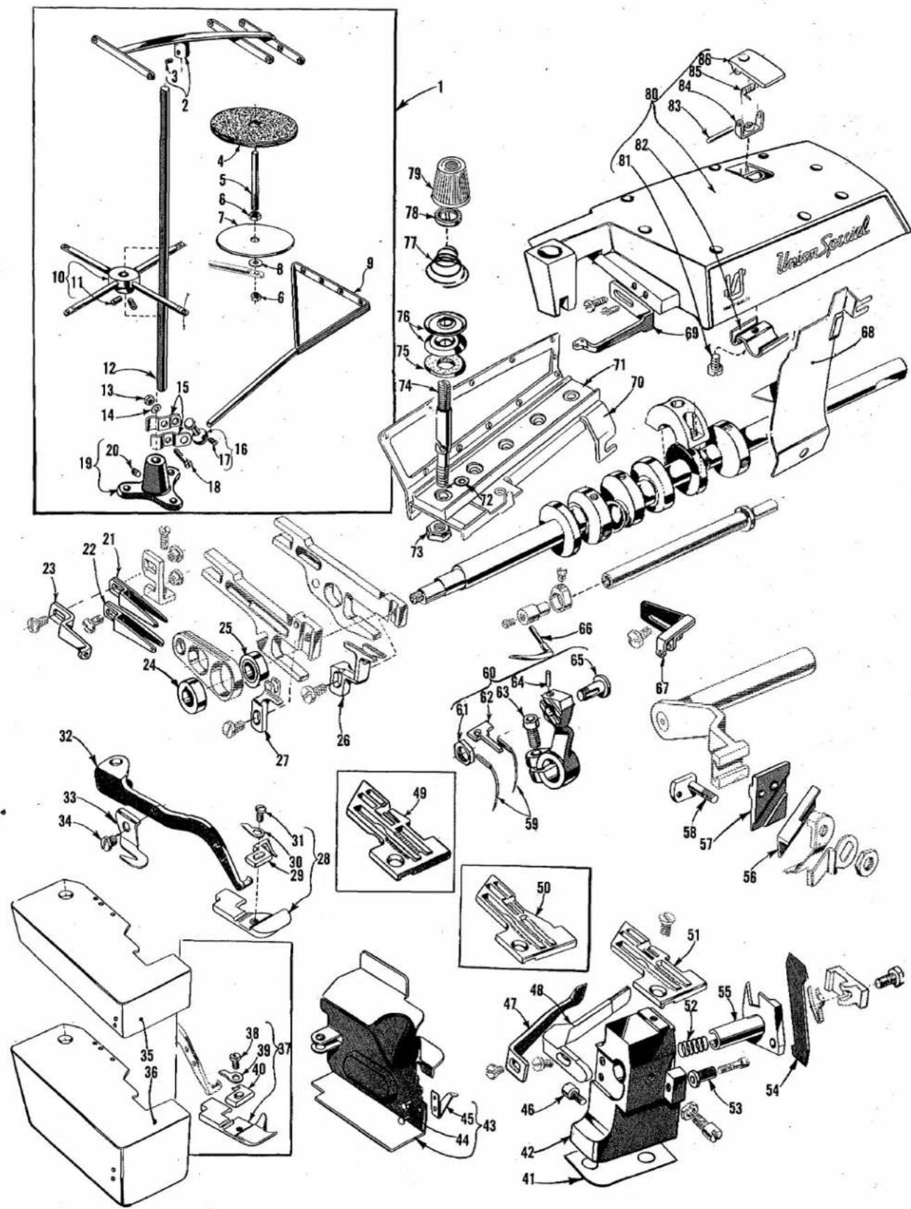
Technical diagram of a mechanical assembly with numbered parts and labeled parts, including a Union Speed valve.The parts illustrated on pages 16 and 18 and described on this page and page 19 represent the parts that are used on Styles 39500 QW, RG and RH, but not used on Style 39500 QP.
Unless otherwise specified in the description, the parts are used on all the machine styles covered in this catalog. Those parts shown in phantom views and bearing no reference numbers are common to Styles 39500 QP, QW, RG and RH.
Use Catalog No. 103 QA (Style 39500 QP) for all parts not illustrated or described in this catalog.
Reference numbers that are inside a bracket or box on the picture plates and have indented descriptions, indicate they are components of a complete part or assembly.
| Ref. No. | Part No. | Description | Amt. Req. |
| 1 | 21101 H-4 | Thread Stand, complete | 1 |
| 2 | 21114 H-4 | Eyelet Support | 1 |
| 3 | 22651 CD-4 | Screw, for eyelet support | 1 |
| 4 | 21104 V | Pad, for thread cone | 4 |
| 5 | 21114 W | Spool Pin | 4 |
| 6 | 258 A | Nut, for spool pin | 8 |
| 7 | 21114 | Spool Seat Disc | 4 |
| 8 | 652-16 | Washer, for spool seat disc | 4 |
| 9 | 21114 S-4 | Lead Eyelet | 1 |
| 10 | 21114 D-4 | Spool Seat Support | 1 |
| 11 | 22651 CD-5 | Screw, for spool seat support | 2 |
| 12 | 21104 B-20 | Thread Stand Rod | 1 |
| 13 | 21104 H | Nut, for lead eyelet ball split socket | 1 |
| 14 | 652-16 | Washer, for lead eyelet ball split socket | 1 |
| 15 | 21114 U | Lead Eyelet Ball Split Socket | 2 |
| 16 | 21114 T | Lead Eyelet Socket Ball | 1 |
| 17 | 22651 CD-4 | Screw, for lead eyelet socket ball | 1 |
| 18 | 22810 | Screw, for lead eyelet ball split socket | 1 |
| 19 | 21114 A | Thread Stand Base | 1 |
| 20 | 22651 CD-4 | Screw for thread stand base | 1 |
| 21 | 39568 T | Upper Looper Thread Eyelet, for Styles 39500 RG and RH | 1 |
| - | 39568 L | Upper Looper Thread Eyelet, for Style 39500 QW | 1 |
| 22 | 39568 S | Lower Looper Thread Eyelet, for Styles 39500 RG and RH | 1 |
| - | 39568 B | Lower Looper Thread Eyelet, for Style 39500 QW | 1 |
| 23 | 39568 U | Auxiliary Looper Thread Eyelet, for Styles 39500 RG and RH | 1 |
| - | 39568 E | Auxiliary Looper Thread Eyelet, for Style 39500 QW | 1 |
| 24 | 39540 B-12 | Main Feed Driving Eccentric, for Styles 39500 QW and RH | 1 |
| - | 39540 B-8 | Main Feed Driving Eccentric, for Style 39500 RG | 1 |
| 25 | 39540 B-10 | Differential Feed Driving Eccentric, for Styles 39500 QW and RH | 1 |
| - | 39540 B-8 | Differential Feed Driving Eccentric, for Style 39500 RG | 1 |
| 26 | 39526 W | Differential Feed Dog, marked "AT", 12 teeth per inch, for Styles 39500 QW and RG | 1 |
| - | 39526 Z | Differential Feed Dog, marked "AU", 22 teeth per inch, for Style 39500 RH | 1 |
| 27 | 39505 W | Main Feed Dog, marked "W", 12 teeth per inch, for Styles 39500 QW and RG | 1 |
| - | 39505 Z | Main Feed Dog, marked "AC", 22 teeth per inch, for Style 39500 RH | 1 |
| 28 | 39520 AG | Presser Foot, for Style 39500 RG | 1 |
| 29 | 39597 AG | Stitch Tongue, marked "EM" | 1 |
| 30 | 39530 | Hinge Spring | 1 |
| 31 | 22768 B | Screw, for hinge spring and stitch tongue | 1 |
| 32 | 39556 E | Presser Arm, for Style 39500 RG | 1 |
| - | 39556 F | Presser Arm, for Styles 39500 QW and RH | 1 |
| 33 | 39556 K | Chain Cutting Knife, marked "J" | 1 |
| 34 | 22704 | Screw, for chain cutting knife | 1 |
| 35 | 39501 DC | Cloth Plate, for semi or fully submerged installation | 1 |
| 36 | 39501 EC | Cloth Plate, for non-submerged installation | 1 |
| 37 | 39520 W | Presser Foot, for Styles 39500 QW and RH | 1 |
| 38 | 22768 B | Screw, for hinge spring and stitch tongue | 1 |
| 39 | 39530 | Hinge Spring | 1 |
| 40 | 39597 W | Stitch Tongue, marked "EF" | 1 |
| 41 to 87 | See following page | ||
* Will be furnished in place of No. 39501 DC if non-submerged installation is specified.
text_image
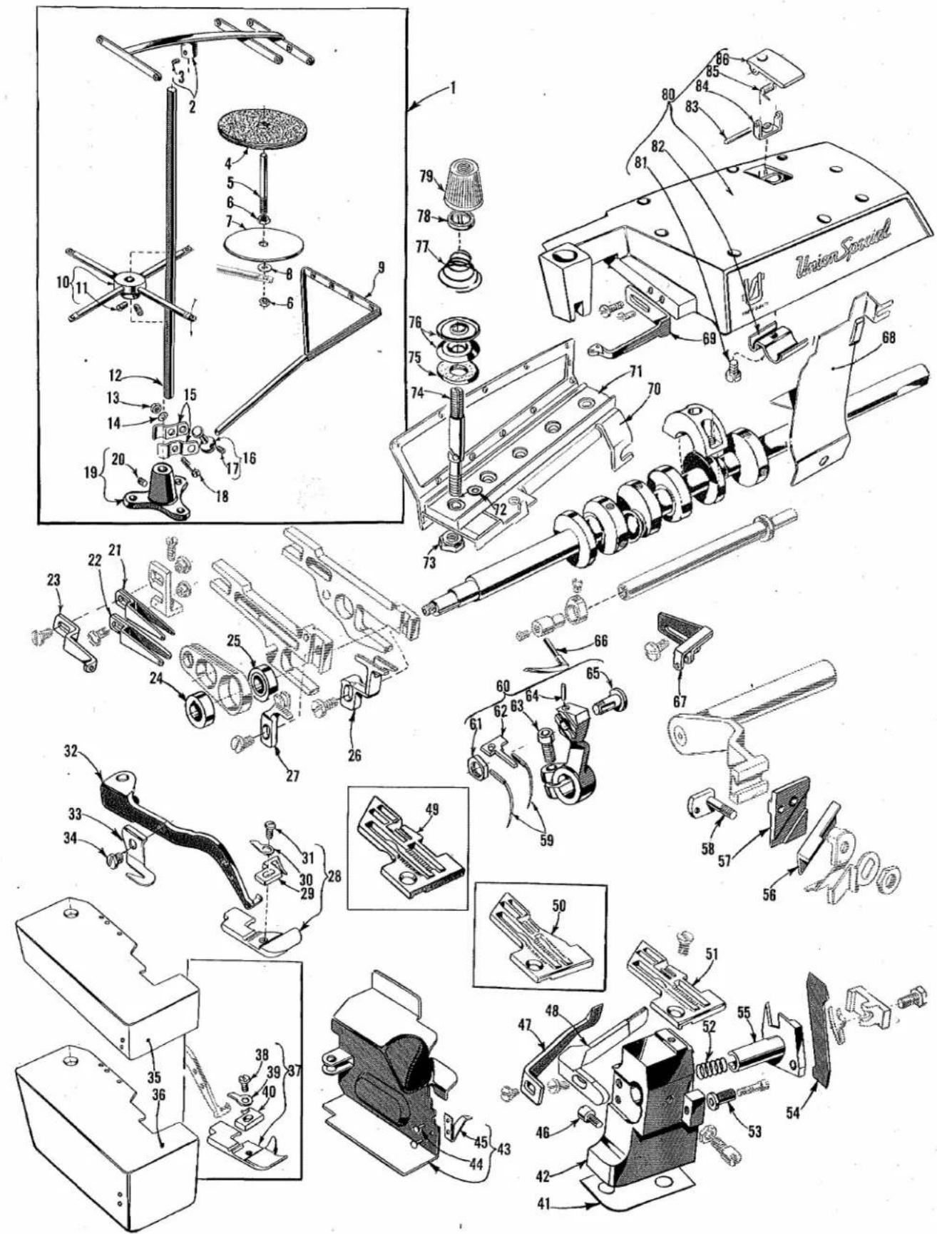
Technical diagram of a mechanical assembly with numbered parts and labeled parts, including a Union Speed component.| Ref. No. | Part No. | Description | Amt. Req. |
| 1 to 40 | See preceding page | ||
| 41 | 39580 E | Shim, .028 inch (.71 mm), for throat plate and lower knife support bracket | 1 |
| 42 | 39580 AE | Throat Plate and Lower Knife Support Bracket | 1 |
| 43 | 39582 GG | Side Cover | 1 |
| 44 | 39582 J | Rivet | 2 |
| 45 | 39582 H | Spring | 1 |
| 46 | 22585 G | Latch Screw, for side cover | 1 |
| 47 | 39525 M | Needle Guard, front | 1 |
| 48 | 39525 P | Needle Guard, rear | 1 |
| 49 | 39524 W | Throat Plate, marked "AN", for Style 39500 QW | 1 |
| 50 | 39524 AG | Throat Plate, for Style 39500 RG | 1 |
| 51 | 39524 Z | Throat Plate, marked "AU", for Style 39500 RH | 1 |
| 52 | 39550 P | Knife Holder Spring, for Style 39500 RG | 1 |
| - | 39550 E | Knife Holder Spring, for Styles 39500 QW and RH | 1 |
| 53 | 39550 R | Lower Knife Holder Locating Stud, for Style 39500 RG | 1 |
| - | 39550 C | Lower Knife Holder Locating Stud, for Styles 39500 QW and RH | 1 |
| 54 | 39549 J | Lower Knife | 1 |
| 55 | 39550 U | Lower Knife Holder | 1 |
| 56 | 39570 J | Upper Knife | 1 |
| 57 | 39572 A | Upper Knife Holder Block, for Style 39500 RG | 1 |
| - | 39572 | Upper Knife Holder Block, for Styles 39500 QW and RH | 1 |
| 58 | 39571 C | Upper Knife Clamp Stud, for Style 39500 RG | 1 |
| - | 39571 D | Upper Knife Clamp Stud, for Styles 39500 QW and RH | 1 |
| 59 | 154 GAS | Needle | 2 |
| 60 | 39552 AC | Needle Driving Arm, marked "N" | 1 |
| 61 | 14077 A | Nut, for needle clamp stud | 1 |
| 62 | 39551 G | Needle Spacer | 1 |
| 63 | 22596 E | Clamp Screw | 1 |
| 64 | 61351 K-625 | Pin | 1 |
| 65 | 39551 J | Needle Clamp Stud | 1 |
| 66 | 39508 C | Upper Looper, marked "CJ", for Styles 39500 RG and RH | 1 |
| - | 39508 A | Upper Looper, marked "CC", for Style 39500 QW | 1 |
| 67 | 39563 U | Needle Thread Eyelet, for Styles 39500 RG and RH | 1 |
| - | 39563 H | Needle Thread Eyelet, for Style 39500 QW | 1 |
| 68 | 39578 U | Chip Guard | 1 |
| 69 | 39563 W | Top Cover Needle Thread Eyelet | 1 |
| 70 | 39592 AG-5 | Tension Post Mounting Bracket | 1 |
| 71 | 39592 AN | Tension Post Bar | 1 |
| 72 | 8372 A | Washer, for tension post | 4 |
| 73 | 39592 AH | Nut, for thread tension post | 4 |
| 74 | 39592 AL | Tension Post | 4 |
| 75 | 39592 AF | Tension Disc Felt | 4 |
| 76 | 39592 AD | Tension Disc | 8 |
| 77 | 39592 AR-4 | Looper Thread Tension Spring | 2 |
| - | 39592 AR-8 | Needle Thread Tension Spring | 2 |
| 78 | 39592 AK | Tension Spring Ferrule | 4 |
| 79 | 39592 Z | Left Needle Thread Tension Nut, yellow | 1 |
| - | 39592 AA | Right Needle Thread Tension Nut, green | 1 |
| - | 39592 AB | Upper Looper Thread Tension Nut, blue | 1 |
| - | 39592 AC | Lower Looper Thread Tension Nut, red | 1 |
| 80 | 39582 AK | Top Cover | 1 |
| 81 | 22562 A | Screw, for oil guard | 1 |
| 82 | 39582 W | Oil Guard | 1 |
| 83 | 51-103 Blk. | Hinge Pin | 1 |
| 84 | 39582 AG | Hinge Bracket | 1 |
| 85 | 39582 V | Spring | 1 |
| 86 | 39582 AF | Oil Filler Cover | 1 |

natural_image
Black-and-white world map grid showing continents and latitude/longitude lines (no text or labels)WORLDWIDE SALES AND SERVICE
Union Special Corporation maintains sales and service facilities throughout the world. These offices will aid you in the selection of the right sewing equipment for your particular operation. Union Special Corporation representatives and service technicians are factory trained and are able to serve your needs promptly and efficiently. Whatever your location, there is a qualified representative to serve you.
Corporate Office:
One Union Special Plaza
Huntley, IL 60142
Phone: 708·669·5101
Fax: 708·669·1096
European Distribution Center:
Union Special GmbH
Raiffeisenstrasse 3
D-71696 Möglingen, Germany
Tel: 49-07141-247-0
Fax: 49·7141·247·100
Brussels, Belgium
Charlotte, N.C.
Commerce, CA
El Paso, TX
Hong Kong, China
Huntley, IL
Leicester, England
Lille, France
Miami, FL
Milan, Italy
Mission, TX
Möglingen, Germany
Montreal, Quebec
Osaka, Japan
Other Representatives throughout all parts of the world.

Finest Quality
Union Special® INDUSTRIAL SEWING EQUIPMENT