SP172S800MACC - Sewing machine Union Special - Free user manual and instructions
Find the device manual for free SP172S800MACC Union Special in PDF.

User questions about SP172S800MACC Union Special
0 question about this device. Answer the ones you know or ask your own.
Ask a new question about this device
Download the instructions for your Sewing machine in PDF format for free! Find your manual SP172S800MACC - Union Special and take your electronic device back in hand. On this page are published all the documents necessary for the use of your device. SP172S800MACC by Union Special.
USER MANUAL SP172S800MACC Union Special
text_image
Finest Quay SPK1500 P22 Union Special SPK1500P22 SPK1500 P22SP100 SERIES
CYLINDERBED OVERLOCK MACHINE

Finest Quality
Union Special
INDUSTRIAL SEWING EQUIPMENT
First Edition
Copyright 1991
PREFACE
This Engineer's Manual is written for the technical personnel who are responsible for the service and maintenance of the machine. The Instruction Manual for these machines intended for the maintenance personnel and operators at an apparel factory contains operating instructions in detail. And this manual describes "Standard Adjustment", "Adjustment Procedures", "Results of Im proper Adjustment", and other important information which are not covered by the Instruction Manual.
It is advisable to use the relevant Instruction Manual and Parts List together with this Engineer's Manual when carrying out the maintenance of these machines.
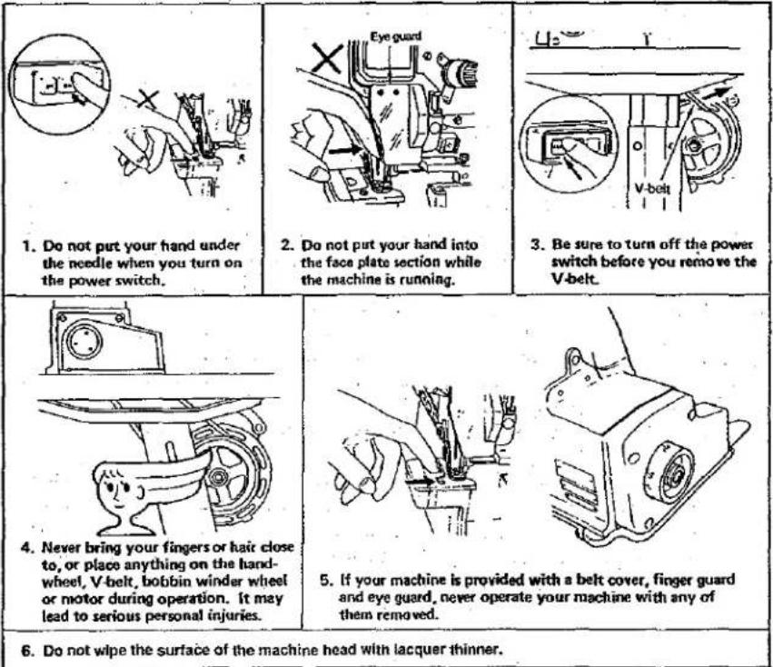
CAUTIONS
-
Do not put your hand under the needle when you turn on the power switch.
-
Do not put your hand into the face plate section while the machine is running.
-
Be sure to turn off the power switch before you remove the V-belt.
-
Never bring your fingers or hair close to, or place anything on the handwheel, V-belt, bobbin winder wheel or motor during operation. It may lead to serious personal injuries.
-
If your machine is provided with a belt cover, finger guard and eye guard, never operate your machine with any of them removed.
-
Do not wipe the surface of the machine head with lacquer thinner.
-
If your machine is equipped with a clutch type motor, the motor will be kept running by inertia after turning OFF the power switch.
It is dangerous to depress the foot pedal of the sewing machine while the motor is still running, because the sewing machine will start rotating abruptly. Be sure to keep the foot pedal of the sewing machine held depressed after turning OFF the power switch until the sewing machine completely stops. - When you leave from your machine, make sure to turn OFF the power to it.
- In case of a power failure, make sure to turn OFF the power to the machine.
- When you leave from your machine, make sure to turn OFF the power to it.
- In case of a power failure, make sure to turn OFF the power to the machine.
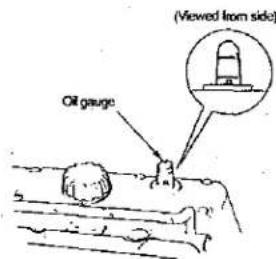
BEFORE OPERATION
text_image
(Viewed from side) Oil gauge- If the pointer bar of the oil gauge comes down under the lower marker line when observing the oil gauge from sideward, supply oil referring to the description of "5. Lubrication."
text_image
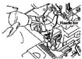
Needle bar
text_image
Upper looper guide- Apply two or three drops of oil to the needle bar and upper looper guide when operating the machine for the first time after setup or after a long period of disuse.
text_image
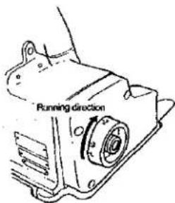
Running direction- The correct machine running direction is such that the handwheel turns clockwise as viewed from the handwheel's side. Never run the machine in the reverse direction.
CONTENTS
-
SPECIFICATIONS 2
-
MODEL NUMBERING SYSTEM 3
-
STANDARD ADJUSTMENT (FOR MAIN UNIT) 4
(1) Adjusting the needle height 4
(2) Positioning the throat plate....4
(3) Installing position of the needle clamp 4
(4) Adjusting the lower looper 6
(5) Position of the upper looper guide 8
(6) Positioning the upper looper holder 8
(7) Positioning the upper looper 10
(8) Positioning the needle guard 12
(9) Adjusting the height of the feed dog 12
(10) Adjusting the tilt of the feed dog.... 14
(11) Changing the differential feed ratio 14
(12) Longitudinal position of the feed bar 16
(13) Positioning the presser foot 18
(14) Positioning the upper knife arm shaft 18
(15) Positioning the upper and lower knives, and available overedge widths.... 18
(16) Resharpening of the knife 20
(17) Adjusting the looper cover 20
(18) Adjusting the cloth chip cover 22
(19) Adjusting the needle mechanism 24
(20) Position of the upper looper lubricating pin 26
(21) Position of the thread guides and the looper thread take-ups 28
- ADDITIONAL INFORMATION AND PRECAUTIONS 30
(1) Thread tension 30
(2) Upper looper of the SP 100 31
(3) Center-to-center distance of the upper looper holder 32
(4) Caution in assembly 32
(5) Kinds of motor pulleys, belts and frame support plate bolts.... 35
-
ADJUSTMENT OF THE NEEDLE HEIGHT AND LOOPER TIMING 36
-
TROUBLES AND CORRECTIVE MEASURES 37
-
DIMENSIONS OF TABLE (SEMI-SUNKEN TYPE) 42
(1) Semi-sunken type 42
- SPECIFICATIONS
SP 100 Series
| 1 | Model | SP151/161 (*: SP151, 161) | SP 172 |
| 2 | Description | 1-needle Overlock machine | 2-needle Overlock machine |
| 3 | Stitch type F.S.T. | 504 | 514 |
| 4 | Sewing speed (max.) | 8,500 s.p.m. | 8,000 s.p.m. |
| 5 | Stitch length | 0.8 ~ 3.5 mm | |
| 6 | Needle gauge (mm) | — | 2, 2.4 |
| 7 | Overedging width (mm) | 3.2, 4, 4.8 | 2, 3.2, 4, 4.8 |
| 8 | Differential feed ratio | Gathering 1:2.3 (Max. 1:4.5), Stretching 1:0.8 | |
| 9 | Needle bar stroke | 24.3 mm | |
| 10 | Needle tilt angle | 20° | |
| 11 | Needle | DC x 27 (standard) | |
| 12 | Presser lifting amount (mm) | 5.5 mm | 6.0 mm |
| 13 | Presser foot pressure | Max. 6 kg | |
| 14 | Stitch adjusting method | By pushbutton | |
| 15 | Upper knife | Square knife (standard) | |
| 16 | Differential feed adjustment | By lever | |
| 17 | Weight | 28 kg | |
| 18 | Lubrication | Gear-type automatic lubrication | |
| 19 | Lubricating oil | New Defrix Oil No. 2 | |
| 20 | Needle cooler | By silicon oil lubricating unit for the needle tip | |
| 21 | Needle thread heat remover | By silicon oil lubricating unit for the needle thread | |
| 22 | Motor | 2P 550 W (for 7,500 s.p.m. or more)2P 400 W (below 7,500 s.p.m.) | |
NUMBERING SYSTEM FOR SP100 MACHINES

flowchart
graph TD
    A["SP 1 7 2 S 9 00 M AC C"] --> B["BASIC FRAME"]
    B --> C["OVERLOCK STRAIGHT"]
    C --> D["SP NEEDLE CYL BED"]
    A --> E["STITCH TYPE"]
    E --> F["STITCH TYPE: 5, 502, 503, 504, 505, 506, 507, 512, 514, 521"]
    A --> G["FEED TYPE"]
    G --> H["FEED TYPE: 8, 2 ROW DIFF. FEED, 9, 3 ROW DIFF. FEED"]
    A --> I["ATTACHMENTS / FEATURES"]
    I --> J["ATTACHMENTS: 00, NO ATTACHMENTS"]
    I --> K["ADJUSTABLE HEMMER: 29, ADJUSTABLE HEMMER: 30, W/SWITCH DEVIATION"]
    A --> L["SEWING CAPACITY"]
    L --> M["M MEDIUM H HIGH"]
    A --> N["NEDLE GAUGE/OVEREDGE WIDTH"]
    N --> O["CODE MM INCHES AA 2.0-2.0 5/64 - 5/64 AC 2.0-3.2 5/64 - 1/8 AD 2.0-4.0 5/64 - 5/32 AE 2.0-4.8 5/64 - 3/16 BD 2.4-4.0 3/32 - 5/32 BE 2.4-4.8 3/32 - 3/16 OVEREDGE WIDTH"]
    N --> P["GAUGE MM INCHES 032 3.2 1/8" 040 4.0 5/32" 048 4.8 3/16""]
3. STANDARD ADJUSTMENT (FOR MAIN UNIT)
STANDARD ADJUSTMENT
(1) Adjusting the needle height
When the needle(s) is in the highest position the distance between the needle point(s) and the throat plate surface should be as shown below.
| SP | 151/161 |
| Refer to right Fig. | |
| SP | 172 |
| Refer to right Fig. |

SP161S800 SP161H
| Model | Left needle | Right needle |
| SP151H | 10.0(0.394") | — |
| SP161S△△△△△△△C | 10.5(0.413") | — |
| SP161SM048C | 11(0.433") | — |
| SP172S△△△M△△△ | 10.5(0.413") | 9.1(0.358") |
| SP172S△△△H△△△ | 11(0.433") | 9.6(0.378") |
The adjustment of needle height for the 2-needle overlock machine should be made in reference to the left needle.
(2) Positioning the throat plate
The needle entry point should be such that the distance between the needle slot edge of the throat plate and the needle center.
Overlock side A 1.3(0.051")
(Unit: mm)

natural_image
Mechanical clamp or bracket assembly diagram with threaded end and mounting hole (no text or symbols)(3) Installing position of the needle clamp
The needle clamp connecting stud should fit with the bottom end of the needle bar or spaced 0.5 mm (0.20") or less from it.
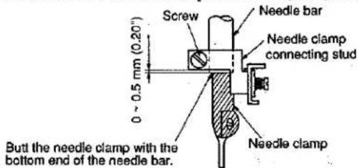
text_image
Screw Needle bar 0 - 0.5 mm (0.20") Needle clamp connecting stud Butt the needle clamp with the bottom end of the needle bar. Needle clamp| ADJUSTMENT PROCEDURES | RESULTS OF IMPROPER ADJUSTMENT |
Take off the upper cover, and loosen the set screw of the needle driving forked crank to perform the adjustment of the needle height.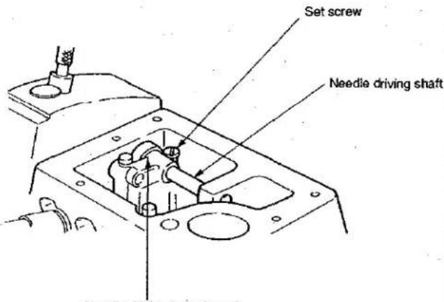 Needle driving forked crank(Caution) Do not fully loosen the set screw of the needle driving forked crank. If the needle driving forked crank has got out of position laterally when its set screw was loosened, fully loosen the set screw and turn pulley to allow the forked crank to turn until it settles by itself. Then tighten the set screw to fix the forked crank at that position. Needle driving forked crank(Caution) Do not fully loosen the set screw of the needle driving forked crank. If the needle driving forked crank has got out of position laterally when its set screw was loosened, fully loosen the set screw and turn pulley to allow the forked crank to turn until it settles by itself. Then tighten the set screw to fix the forked crank at that position. | Any other needle height than specified here will badly affect the action of the lower looper, the timing for catching the upper looper thread, etc.Improper lateral position of the needle driving forked crank will cause seizure, play, or other troubles.Improperly positioned throat plate will cause needle breakage, contact of the needles with the throat plate, or other troubles. |
Loosen the set screws of the throat plate base to make the adjustment.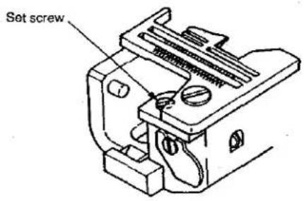 | Improperly positioned throat plate will cause needle breakage, contact of the needles with the throat plate, or other troubles. |
| Loosen the screw and adjust, by slightly turning the needle clamp, the clearance provided between the right-hand side needle and the lower looper (for 2-needle overlock machine). | If the clearance provided between the needle and the looper is excessive, the needle thread will be likely to skip at the time of tucking.If the clearance provided between the needle and the looper is insufficient, the needle will break or the looper blade point will be damaged causing thread breakage. |
STANDARD ADJUSTMENT
(4) Adjusting the lower looper
1) Looper gauge of the lower looper
The distance between the blade point of the lower looper and the center of the needle should be as follows when the lower looper is at the extreme left of its stroke.

text_image
Lower looper Stop pin Lower looper support arm Fine adjustment screw Set screw 67.4 ± 0.2 mm 2.654 ± 0.008"| Model | Looper gauge of the lower looler | |
| 1-needle overlock machine | SP151SP161HSP161S | 4.0±0.3(0.157±0.012") |
| SP161S800M048CSP161S900M032CSP161S900M040C | 3.6±0.3(0.142±0.012") | |
| 2-needle overlock machine | SP172S△△M△△ | 3.6±0.3(0.142±0.012") |
| SP172S△△△H△△ | 4±0.3(0.157±0.012") | |
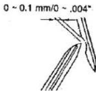
2) Clearance between the lower looper and the needle
The clearance should be 0 to 0.1 mm. (.004")
| ADJUSTMENT PROCEDURES | RESULTS OF IMPROPER ADJUSTMENT |
| Loosen the set screw of the lower looper support arm to make adjustment of the returning amount of the lower looper.(Referential Information) 1. The radius of the lower looper will be 67.4 mm (2.654±.008") when the lower looper is inserted into the support arm until it contacts the stop pin and then fixed.The rocking angle of the lower loop-er will be 27°. | Excessive return of the lower looper tends to cause stitch skipping when filament thread is used.Insufficient return of the lower looper tends to cause needle thread stitch skipping when mixed yarn is used. |
| Loosen the screw in the lower looper supporting arm until it is temporarily tightened. Then, finely adjust the longitudinal position of the looper using the fine adjustment screw.Turn the fine-adjusting screw clockwise to move the lower looper closer to the needle.Turn it counterclockwise to move the lower looper away from the needle. | Excessive clearance will often cause needle thread stitch skipping.Insufficient clearance will cause needle breakage due to the contact of the looper with the needle, or produce scratches on the blade point of the looper, leading to needle thread breakage or other troubles. |
STANDARD ADJUSTMENT
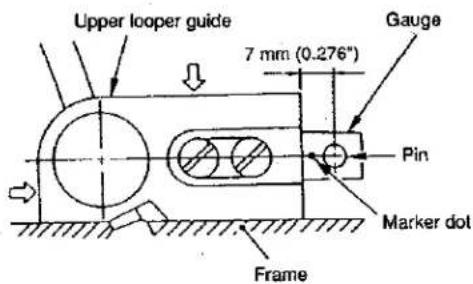
(5) Position of the upper looper guide
Vertical position: To be in close contact with the frame guide surface.
Lateral position: To be pressed against the upper looper guide support gauge.
text_image
Upper looper guide 7 mm (0.276") Gauge Pin Marker dot Frame| Upper looperguide support gauge | 5.57(0.276") (0.217")6(0.236") | 5(0.217")6.5(0.256") |
| 11831807 | 11893609 |
| Model | Position of guide support | |
| 1-needle overlock machine | SP-151SP-161HSP-161S | 7(0.276") |
| SP161S900M048C | 6.5(0.256") | |
| 2-needle overlock machine | SP172S△△M△△△ | 7(0.276")[SZKZ] |
| SP172S△△H△△△ | 6.5 (0.256") | |
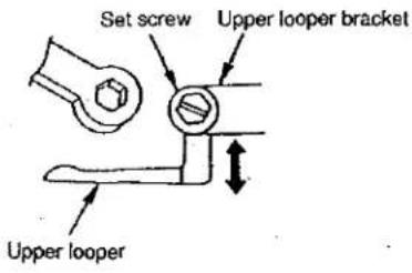
(6) Positioning the upper looper holder
The distance between the bottom surface of the frame and the upper end of the upper looper holder pin should be as shown below when the upper looper holder is at the highest point of its stroke.
| Model | Dimension (E) |
| SP151/161 | 44.85±0.05 mm (1.766"±0.002") |
| SP172 | 47.15±0.05 mm (1.856"±0.002") |
For models other than standard models
| Model | Dimension (E) |
| SP151SP161HSP161S | 44.85±0.05(1.766"±0.002") |
| SP161S800M048CSP161S900M032CSP161S900M040C | 47.15±0.05(1.856"±0.002") |
| SP172S△△△M△△△ | 47.15±0.05(1.856"±0.002") |
| SP172S△△△H△△△ | 48.15±0.05(1.766"±0.002") |

text_image
Upper looper holder pin 53(2.087") Bottom surface of frame Upper looper bracket Upper looper holder Upper looper shaft| ADJUSTMENT PROCEDURES | RESULTS OF IMPROPER ADJUSTMENT |
| ○ Fit the upper looper guide supporting gauge over the gauge fixing pin which has been driven in the frame and secure the gauge with an O ring. Then position the gauge taking the marker dot engraved on it or the chamfering direction as reference.○ When installing the upper looper guide, press it against the gauge while keeping the upper looper guide into close contact with the frame surface, then tighten the screws. | ○ If the upper looper guide has improperly positioned vertically, it will cause oil leakage or disturbed path of the upper loop-er with resultant stitch skipping.○ If the upper looper guide has been inaccurately positioned laterally, it will cause stitch skipping, or contact with the looper. |
| ○ Inaccurately positioned upper looper holder will cause excessive projection of the upper looper, resulting in stitch skipping, or other troubles.○ If the upper looper ball arm has been improperly positioned longitudinally, seizure will result (mainly because the arm sticks when it goes up).(Caution) To adjust the upper looper ball arm, take dimension E as standard. Remember that the projecting amount and the height of the upper loop-er should eventually be properly adjusted. So, confirm the dimensions related to the upper looper. |
STANDARD ADJUSTMENT
(7) Positioning the upper looper
1) Height of the upper looper
The distance between the throat plate surface and the blade point of the looper should be as follows when the upper looper is at the extreme left of its travel.
① SP100 Standard
SP151H 10.7±0.3 mm (0.421"±0.012")
SP161H 10.7±0.3 mm (0.421"±0.012")
SP161S 10.7±0.3 mm (0.421"±0.012")
SP172 10.9±0.3 mm (0.429"±0.012")
For models other than standard models
| Model | Dimension Ⓐ |
| SP151H | 10.7 ± 0.3 mm |
| SP161H | (0.421" ± 0.012") |
| SP161S | 10.9 ± 0.3 mm |
| SP161S800M048C | (0.429" ± 0.012") |
| SP161S900M032C | |
| SP161S900M040C | |
| SP172S△△△M△△△△ | |
| SP161S900M048C | 11.0 ± 0.3 mm |
| SP172S△△△H△△△ | (0.433" ± 0.012") |

text_image
Set screw Upper looper bracket Throat plate2) Longitudinal position of the upper looper
① The clearance between the upper and lower loopers should be 0.1 (0.004") to 0.2 mm (0.008") when they cross with each other.
② The clearance between the upper looper and the needle should be 0 to 0.2 mm. (0.008")

text_image
Upper looper Lower looper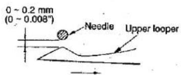
text_image
0 - 0.2 mm (0 - 0.008°) Needle Upper looper| ADJUSTMENT PROCEDURES | RESULTS OF IMPROPER ADJUSTMENT |
| ○ Set a hexagon wrench onto the set screw at the end of the upper looper bracket to adjust the height of the upper looper.When adjusting the height, pay attention also to the clearance produced between the upper looper and lower looper at the time of their crossing. | ○ If the upper looper has been positioned too high, an excessive clearance will be produced between the upper looper and the needle. As the result, the upper looper thread will fail to catch the needle thread, and stitch skipping occur.○ On the contrary, if the upper looper has been positioned too low, the needle point will hit the looper, causing needle breakage. Also the looper will touch other component when the presser foot goes up. |
| ○ Loosen the set screw at the top end of the upper looper bracket to move the looper back or forth for positioning. | ○ Excessive clearance will cause stitch skipping.○ Insufficient clearance will cause the upper looper to come in contact with the lower looper. |
 |
STANDARD ADJUSTMENT
(8) Positioning the needle guard
1) For 1-needle or 2-needle overlock machine
The overlock machine has two needle guards, A and B.
Needle guard A When the blade point of the lower looper reaches the needle center:

text_image
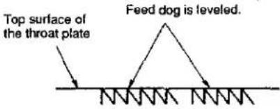
Lightly touch the needle guard A Set screw (1) Pin Needle guard B Throat plate B 0.1 mm (0.004") Set screw When needles are at lowest point of their stroke(9) Adjusting the height of the feed dog
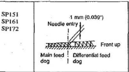
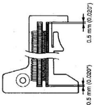
The height of the feed dog should be as follows when it is at its highest position.

| Model | Height of the feed dog |
| SP100 | 1 mm (0.039") |
The auxiliary feed dog is 0.5 mm (0.020") lower than the main feed dog.

text_image
0.5 mm (0.020") Main feed dog Auxiliary feed dog| ADJUSTMENT PROCEDURES | RESULTS OF IMPROPER ADJUSTMENT |
| Adjust the clearance between the needle guard and the needles by the set screws of the needle guard.Loosen the screw and adjust the clearance provided between needle guard and the needle by moving the needle guard back or forth. | Excessively close contact between the needle guard and the needles will lead to needle bend or stitch skipping.A clearance left between the needle guard and the needles will cause the looper blade point to come in contact with the needles, leading to needle or blade point breakage, or other troubles.Excessive clearance between the needle guard and the needle will cause stitch skipping due to needle shake. On the contrary, insufficient clearance will cause the needle guards to catch the needles between them, leading to wear on the needle guards and scratches on the needles. |
Perform adjustment by the set screws. | If the feed dogs are too high, the needles will be deflected and broken when sewing heavy-weight materials. The feed dogs will tend to suffer scratches when sewing light-weight materials. Puckering will frequently occur.If the feed dogs are too low, insufficient feed power will result.If the auxiliary feed dog is too high, chain-off thread will be often jammed.If the main feed dog and differential feed dog are set at different heights, proper differential feeding action will be hindered. |
| STANDARD ADJUSTMENT | |
| (10) Adjusting the tilt of the feed dogWhen the feed dogs have come up most, they should be flat. | When the feed dog juts out the top surface of the throat plate. |
 |  Adjust the inclination of the feed dog when it is in its highest position so that the feed dog is flush with the throat plate when the feed dog juts out the throat plate. Adjust the inclination of the feed dog when it is in its highest position so that the feed dog is flush with the throat plate when the feed dog juts out the throat plate. |
| (11) Changing the differential feed ratioDifferential feed ratio is normally changed by the differential feed adjusting lever. If a larger differential feed ratio is required for sewing, change the position of the main feed pin. | |
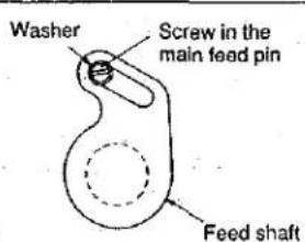 (Standard position)The pin should be positioned at the highest position in the slot.(Standard) Gathering: 1 : 2.3Stretching: 1 : 0.8 (Standard position)The pin should be positioned at the highest position in the slot.(Standard) Gathering: 1 : 2.3Stretching: 1 : 0.8 | 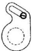 The pin is positioned at the lowest position in the slot.(Max. gathering) Gathering: 1 : 4.5Stretching: 1 : 1.4 The pin is positioned at the lowest position in the slot.(Max. gathering) Gathering: 1 : 4.5Stretching: 1 : 1.4 |
| ADJUSTMENT PROCEDURES | RESULTS OF IMPROPER ADJUSTMENT |
The feed bar shaft consists of an eccentric shaft. Loosen the set screw to perform adjustment.Remove the flange rubber cap from the rear of the machine, and loosen the screw.Remove the flange rubber cap and turn the feed bar shaft.When the slit on the shaft is leveled and the marker dot on it is positioned this side (toward the operator)..... The feed dog is leveled.When the marker dot is raised above the standard position..... The feed dog is positioned with this side, toward the operator, raised (in the direction of the arrow).When the marker dot is lowered under the standard position..... The feed dog is positioned with this side, toward the operator, lowered.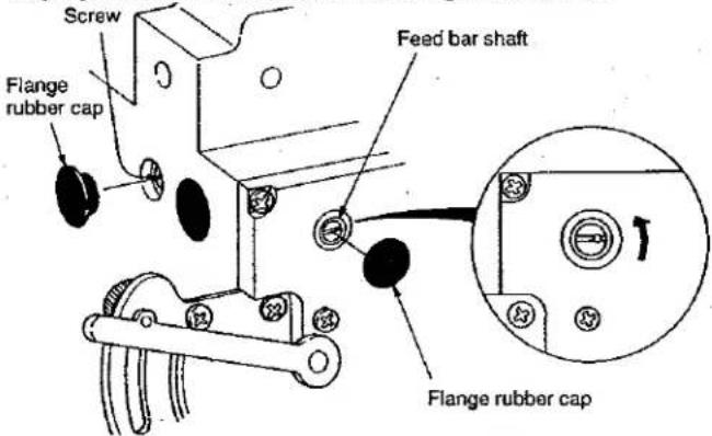 | When tilted with the front up Good material catching will be obtained.When tilted with the front down Uneven feed and puckering will be effectively prevented. |
Remove the cap from the feed adjusting hole located on the left-hand side face of the frame. Then, loosen the screw in the main feed pin and adjust the position of the main feed pin.When the pin is set at its highest position..... StandardWhen the pin is set at its lowest position..... Max. gathering is obtained. | |
STANDARD ADJUSTMENT
(12) Longitudinal position of the feed bar
When the feed pitch is maximized and the differential feed ratio is also maximized, the front and rear ends of the feed dog should be spaced approximately 0.5 mm away from the corresponding edges of the slot in the throat plate.
text_image
0.5 mm (0.020°) 0.5 mm (0.020°)| ADJUSTMENT PROCEDURES | RESULTS OF IMPROPER ADJUSTMENT |
Remove the oil reservoir. Loosen the clamping screws in the feed connection crank and differential feed arm and adjust the feed bars.To adjust only the differential feed bar, loosen the differential feed arm clamping screw. Then perform the adjustment.To adjust only the main feed bar, loosen the feed connection crank clamping screw. Then perform the adjustment.When the main feed bar is adjusted, the differential feed bar also moves out of position. So, after you have adjusted the main feed bar, loosen the clamping screw in the differential feed bar and properly adjust the position of the differential feed bar.To adjust both the main feed bar and the differential feed bar, adjust first the main feed bar, then adjust the differential feed bar.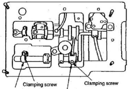 Differential feed arm Feed connection crank Differential feed arm Feed connection crank | If the clearance provided between the throat plate and the feed dog is too small, they will come in contact with each other when the sewing machine runs at high speed. |
| STANDARD ADJUSTMENT |
(13) Positioning the presser footThe presser foot should be positioned so that the feed dogs go down under the specified presser foot pressure, and the presser foot sole comes in contact evenly with the throat plate surface. 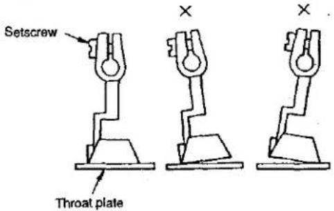 |
(14) Positioning the upper knife arm shaftThe upper knife shaft should be positioned 34 mm (1.339") above the top surface of the throat plate when it is at its highest position.  |
(15) Positioning the upper and lower knives, and available overedge widths1) Lower knifeThe vertical position of the lower knife should be adjusted to make its blade top end flush with the throat plate top surface. The lateral positioning should be done in accordance with a desired overedging width.2) Upper knifeThe upper knife should be positioned vertically so that it engages with the lower knife 0.5(0.020") to 1 mm (0.039") when the upper knife is at the lowest point of its travel.The lateral positioning should be done in accordance with a desired overedging width.3) Overedging widthOveredging widths from 2 (0.079") to 4.8 mm (0.189") are obtainable by replacing the components or by using subclass machines.  |
| ADJUSTMENT PROCEDURES | RESULTS OF IMPROPER ADJUSTMENT |
| Loosen the set screw, and perform adjustment so that the presser foot bottom comes in contact evenly with the throat plate top surface.Accurate adjustment can be made by using two pieces of thin paper to check for even drawing-out tension.Even contact of the presser foot with the throat plate top surface is achieved rather easily by tightening the screw while pushing the right side of the presser foot downward. | Uneven contact will result in bad straight material feed, weak feed power, or puckering. |
| Removing the upper cover, loosen the set screws of the upper knife driving arm, and turn the upper knife shaft to perform vertical positioning.(Caution) Be sure to fully tighten the set screws since the knife shaft is subjected to high loads. | Improperly positioned upper knife arm shaft will come in contact with the frame. If it is moved with the position of the upper knife unchanged, proper engagement of the knives will be disturbed, prohibiting sharp cutting of the knives. |
| Lower knifeLoosen screw 2 and adjust so that the top edge of the knife 1 is aligned with the top surface of the throat plate.Upper knifeLoosen screw 4 and adjust so that the upper knife overlaps the lower knife 1 by 0.5 to 1 mm when upper knife 3 comes down to the lowest point of its stroke.Overedging widthLoosen screw 5 , and fix lower knife 1 while pressing it to the left. Loosen screw 6 , and move upper knife 3 until the specified position is reached. Then, fix upper knife 8 there.Bring the upper knife to the lowest position and loosen screw 5 . Move the lower knife until it comes in contact with the upper knife, then tighten screw 5.(Caution) 1. If the lower knife is used, be sure to tighten screw 5. After the adjustment, check the sharpness of the knives by cutting a single strand of thread at the front and rear of cutting surface. | The lower knife, if positioned too high, will catch materials or cause no contact of the presser foot with the throat plate top surface.If the lower knife is positioned too low, the cutting width will be changed or materials will be caught by the lower knife.The upper knife, if positioned too high, will fail to cut materials.Unsharp cutting or abnormal wear on the knives will result unless the lower knife is laterally positioned and fixed at a position where it has settled by itself under the upper knife spring. |
| STANDARD ADJUSTMENT |
(16) Resharpening of the knife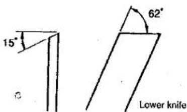 |
(17) Adjusting the looper cover○ The looper cover should smoothly close when slowly closing the looper cover with the upper knife in the lowest position of its stroke.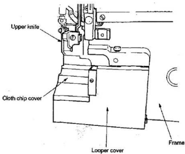 |
| ADJUSTMENT PROCEDURES | RESULTS OF IMPROPER ADJUSTMENT |
| When the lower knife has become dull, fully resharpen it.In principle, no resharpening of the upper knife is done. When the upper knife has become dull, replace it. (This is because the upper knife is a serrated carbide knife.) | If the 15° angle of the lower knife is exceeded, the durability of the knife will be deteriorated, often resulting in blade chipping.If the angle is smaller than 15°, the knife will be dull.If the 62° angle is not observed, the knife may catch materials. |
Close the looper cover, loosen the screw, and move the looper cover guide plate back and forth until the looper cover is brought to a position where the cover smoothly closes.Move the looper cover guide plate until it slightly comes in contact with the looper cover receiving bracket. Now, fix the guide plate by tightening the screw.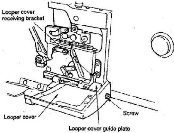 |
STANDARD ADJUSTMENT
(18) Adjusting the cloth chip cover
- When the cloth chip cover is pressed away from you, it should not rattle.
In addition, the cloth chip cover should not come in contact with the upper knife nor the lower looper.

text_image
Lower looper Upper knife Looper cover Cloth chip cover stop Screw Cloth chip cover Two screws in the cloth cover (Located inside)| ADJUSTMENT PROCEDURES | RESULTS OF IMPROPER ADJUSTMENT |
| Temporarily tighten the screw with the cloth chip cover stop raised.Loosen the screw in the cloth chip cover, and adjust the longitudinal position of the cloth chip cover.Loosen the screw in the cloth chip cover stop again, and press the cloth chip cover stop downward until the stop slightly comes in contact with the looper cover. Now, tighten the screw.Finally, confirm that the cloth chip cover comes in contact with neither the upper knife nor the looper. |
STANDARD ADJUSTMENT
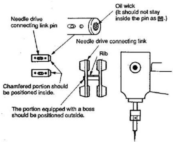
(19) Adjusting the needle mechanism
text_image
Needle drive connecting link pin Chamfered portion should be positioned inside. The portion equipped with a boss should be positioned outside. Oil wick (It should not stay inside the pin as [10.] Needle drive connecting link RibThe oil wick in the needle drive connecting pin should be flush with the chamfered plane of the pin. (If the oil wick sinks inside the chamfered plane, oil will not be fed smoothly.)
- Assemble the needle drive connecting link components so that the portion equipped with a boss comes outside. In addition, the rib located at the center of the link should face upward.
○ A clearance of 0.1 mm (0.004") should be provided between the needle lubricating pin and the needle drive connecting link. (Assemble them using a 0.1 mm (0.004") spacer.)
○ Install the oil lubricating pin in place with its oil inlet faced above.

text_image
Screw Oil inlet Needle lubricating pin Needle drive connecting link| ADJUSTMENT PROCEDURES | RESULTS OF IMPROPER ADJUSTMENT |
| Remove the top cover, side cover and brand label.Remove the rubber plug located under the brand label.If the top cover gasket has been adhered to the frame, also remove the gasket.Loosen the screw in the needle lubricating pin, and remove the pin. | If the oil wick is installed in the needle drive connecting link pin inside the pin as ,oil will not lubricated properly resulting in seizure. |
 Loosen the screw in the needle drive connecting link .Fitting the needle drive connecting link pin in the hole in the frame, thrust the pin until it can be drawn out. Loosen the screw in the needle drive connecting link .Fitting the needle drive connecting link pin in the hole in the frame, thrust the pin until it can be drawn out. Needle drive connecting pin Needle drive connecting pin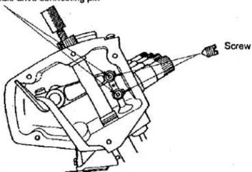 | If the clearance provided between the needle lubricating pin and the needle drive connecting link is too small, the related components will come in contact with each other.If the clearance provided between the needle lubricating pin and the needle drive connecting link is too large, oil will not be fed properly resulting in seizure.If the oil inlet does not face upward, oil will not be fed resulting in seizure. |
STANDARD ADJUSTMENT
(20) Position of the upper looper lubricating pin
1) Orientation of the lubricating pin
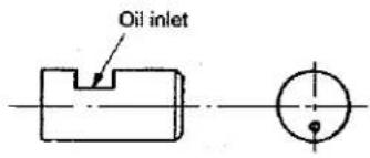
text_image
Oil inletThe oil inlet of the upper looper lubricating pin should face upward.
2) Setting the lubricating pin
Set the lubricating pin in position so that a clearance of 0.1 mm is provided between the upper looper lubricating pin and the upper looper bracket.
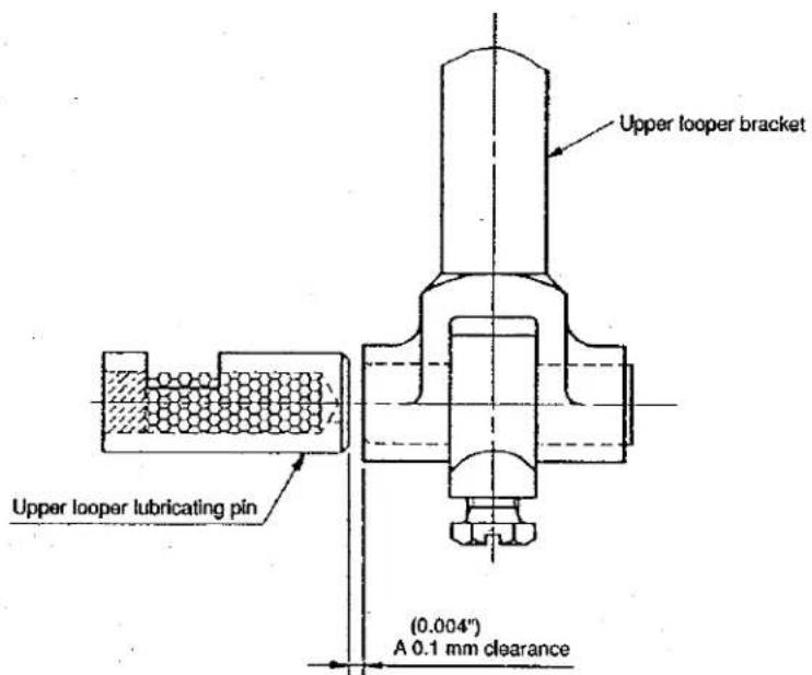
text_image
Upper looper bracket Upper looper lubricating pin (0.004") A 0.1 mm clearance| ADJUSTMENT PROCEDURES | RESULTS OF IMPROPER ADJUSTMENT |
When the upper looper lubricating pin is set in place with the oil inlet faced upward, the lubricating hole is in the lower section as observed from this side.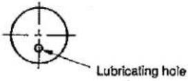 Remove the oil reservoir, loosen the screw and adjust the position of the upper looper lubricating pin. Adjust the clearance provided between the upper looper lubricating pin and the upper looper bracket using a 0.1 mm spacer. Remove the oil reservoir, loosen the screw and adjust the position of the upper looper lubricating pin. Adjust the clearance provided between the upper looper lubricating pin and the upper looper bracket using a 0.1 mm spacer.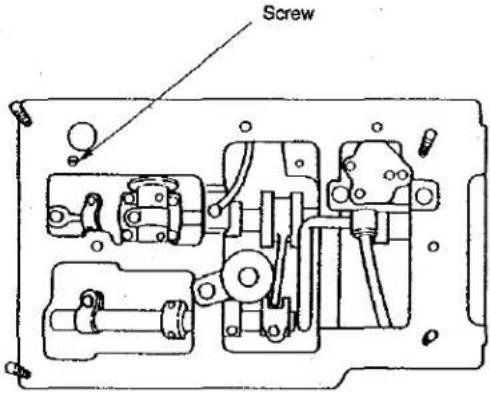 | If the oil inlet does not face upward, oil will not be fed resulting in seizure.If the clearance provided between the upper looper lubricating pin and the upper looper bracket is too small, the related components will come in contact with each other.If the clearance provided between the upper looper lubricating pin and the upper looper bracket is too large, oil will not be fed resulting in seizure. |
STANDARD ADJUSTMENT
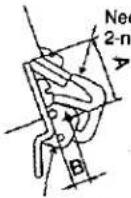
(21) Position of the thread guides and the looper thread take-ups
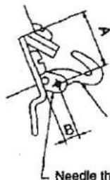
text_image
Needle thNeedle thread take-up
Needle thread take-up lever of 2-needle machine
Needle thread guide
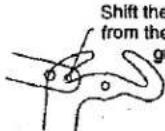
Shift the hook of the thread take-up lever from the thread hole in the needle thread guide by the distance equivalent to 1/3 of the diameter of the hole.
Needle thread guide of 2-needle machine
Shift the hook of the thread take-up lever from the thread hole in the needle thread guide by the distance equivalent to 1/3 of the diameter of the hole.
When the needle thread take-up lever is in its lowest dead point, shift the hook of the thread take-up lever from the thread hole in the needle thread guide by the distance equivalent to 1/3 of the diameter of the hole.
When the needle thread take-up lever is in its lowest dead point, shift the hook of the thread take-up lever from the thread hole in the needle thread guide by the distance equivalent to 1/3 of the diameter of the hole.
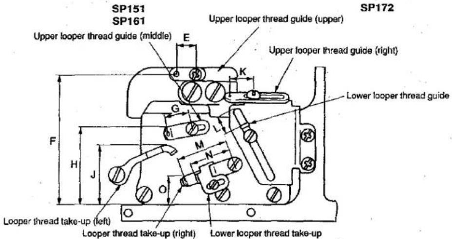
text_image
SP151 SP161 Upper looper thread guide (middle) E K G L H J M N F Lower looper thread guide SP172 Upper looper thread guide (upper) Lower looper thread guide Looper thread take-up (left) Looper thread take-up (right) Lower looper thread take-upRequired adjustment values when the upper looper is at its fully retracted position
| Symbol | SP161S (Standard) | SP172 (Standard) | SP151H, SP161H (Bling hemming) | |||
| General thread | Wooly thread | General thread | Wooly thread | General thread | Wooly thread | |
| A | 15.8 (0.622") | ← | ← | ← | ← | ← |
| B | 4 (0.157") | ← | ← | ← | ← | ← |
| E | 13.5 (0.531") | ← | ← | ← | ← | ← |
| F | Level | ← | ← | ← | ← | ← |
| G | 15 (0.591") | ← | ← | ← | ← | ← |
| H | 42 (1.654") | ← | ← | ← | ← | ← |
| J | 38 (1.496") | ← | ← | ← | ← | ← |
| K | 13 (0.512") | ← | ← | ← | ← | ← |
| L | 6 (0.236") | ← | ← | ← | 17.5 (0.689") | ← |
| M | 28 (1.102") | ← | ← | ← | ← | ← |
| N | 21 (0.827") | ← | ← | ← | ← | ← |
| O | 9 (0.354") | ← | ← | ← | ← | ← |
| ADJUSTMENT PROCEDURES | RESULTS OF IMPROPER ADJUSTMENT |
Perform the adjustment by the set screws.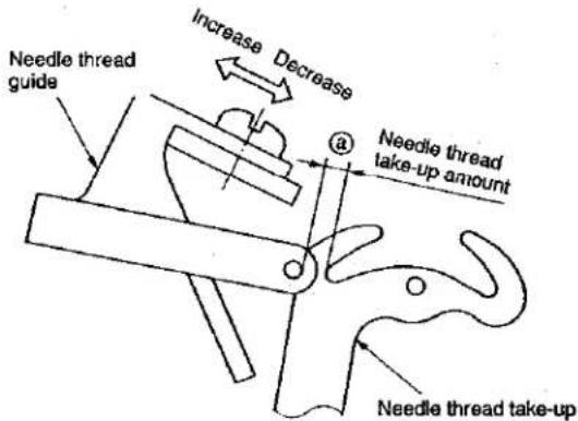 Distance J is related to the vertical intersecting point of the upper and lower looper threads.Set this distance larger for wooly thread, and set smaller for thin thread which is likely to cause stitch skipping.It is desirable to set distance K larger for stretchy threads such as wooly thread.Set distance L a little larger when making blind hemming soft chain stitches.Set distance N a little smaller for blind hemming or making soft chain stitches.Set distance O larger if stitch skipping occurs due to looper thread slack. Set it smaller for better appearance and touch of produced stitches when wooly thread is used. Distance J is related to the vertical intersecting point of the upper and lower looper threads.Set this distance larger for wooly thread, and set smaller for thin thread which is likely to cause stitch skipping.It is desirable to set distance K larger for stretchy threads such as wooly thread.Set distance L a little larger when making blind hemming soft chain stitches.Set distance N a little smaller for blind hemming or making soft chain stitches.Set distance O larger if stitch skipping occurs due to looper thread slack. Set it smaller for better appearance and touch of produced stitches when wooly thread is used. | Distance 3When set smaller, better tightness of needle thread stitches will be obtained.When set larger, loose needle thread stitches will result.Distance E,Fand H exert least influence on stitch formation, however, improper setting of these distances will cause contact between the moving parts.Distance JWhen set larger, the amount of the upper looper thread will be increased.When set smaller, the amount of the upper looper thread will be decreased.Distance KWhen set larger, the amount of the upper looper thread will be increased.When set smaller, the amount of the upper looper thread will be decreased.Distance LWhen set larger, the amount of the lower looper thread will be decreased.When set smaller, the amount of the lower looper thread will be increased.Distance NWhen set larger, the amount of the lower looper thread will be increased.When set smaller, the amount of the lower looper thread will be decreased.Distance OWhen set larger, the amount of the upper and lower looper threads will be decreased.When set smaller, the amount of the upper and lower looper threads will be increased. |
4. ADDITIONAL INFORMATION AND PRECAUTIONS
(1) Thread tension
1) Strength of tension spring and height of tension adjusting nut
| Part No. | Color | Natural length | Operating length | Weight required to compress spring to working length | Height A of nut when “0” is set on the scale |
| 115-50100 | Purple | 19.5mm (0.768") | 11.5mm (0.453") | 910±50g | 54.4±0.5mm (2.142"±0.020") |
| 115-50209 | Green | 19.5 (0.768") | 11.5 (0.453") | 640±50 | 54.4±0.5 (2.142"±0.020") |
| B3101-804-000 | Red | 19.5 (0.768") | 11.5 (0.453") | 430±50 | 54.4±0.5 (2.142"±0.020") |
| B3102-804-000 | Yellow | 17.8 (0.701") | 9.8 (0.386") | 320±35 | 52.7±0.5 (2.075"±0.020") |
| B3103-804-000 | Blue | 17.3 (0.681") | 9.3 (0.366") | 150±20 | 52.2±0.5 (2.055"±0.020") |
| B3121-804-000 | Gray | 13.8 (0.543") | 5.8 (0.228") | 150±20 | 48.7±0.5 (1.917"±0.020") |
2) How to replace the tension spring and set "0" on the scale

text_image
Scale case A Scale shaft pin Tension adjusting nut Spring Spring bush Thread guide plate
text_image
0 mark hole Scale gear Double gear① Remove the tension adjusting nut, scale shaft pin and spring bush, then replace the pin with the exclusive one. When the knob is removed, the scale pin will come off. So, be careful.
② Attach the spring bush and the scale shaft pin in place and screw in the tension adjusting nut. At this time, screw in the knob after aligning the axial direction of the scale shaft pin and the longitudinal direction of the groove inside the knob.
③ Adjust the height of the end face of the knob (dimension A) as measured from the thread guide plate to the value given in the table above.
④ Remove the screw from the thread guide plate. At this time, the scale case and the gear inside the case will come off if the scale case is faced downward. So, be sure to remove the screw from the thread guide plate keeping the scale case held faced upward.
⑤ Remove the scale case.
Remove the double gear.
The scale gear freely rotates. So, position the 0 mark hole straight up. Now, fit the double gear over the scale gear.
⑥ Fit the scale case over the double gear and fix the case with a locknut.
3) Springs used for each model
| Model\Where to use | Needle thread | Upper looper thread | Lower looper thread |
| SP151H | Blue | — | Yellow |
| SP161S | Red | Yellow | Blue |
| SP161H | Yellow | Blue | Yellow |
| SP172 | Red, Yellow | Yellow | Blue |
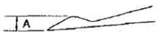
(2) Upper looper of the SP 100
Use a proper upper looper in accordance with the needle No. When ordering, specify the boxed numbers shown in the table at right. The loopers with asterisks will be attached to standard machine heads.
| Model | Nos. engraved on upper looper | Needle No. | Upper looper thickness A |
| SP151 | * 1224 [75] | #9 #11 #14 | 2.05 (0.081") |
| SP161 | * 1224 [73] | #9 #11 #14 | 2.05 (0.081") |
| SP172 | * 1224 [73] | #9 #11 #14 | 2.05 (0.081") |
| SP161S900M048C | * 1224 [71] | #9 #11 #14 | 2.25 (0.089") |
| SP172S900HAC | 1224 [73] | #14 #16 #18 | 2.05 (0.081") |
| SP172S900HAD | |||
| SP172S900HAE | |||
| SP172S900HBD | |||
| SP172S900HBE |
(3) Center-to-center distance of the upper looper holder
The standard center-to-center distances are as shown below.
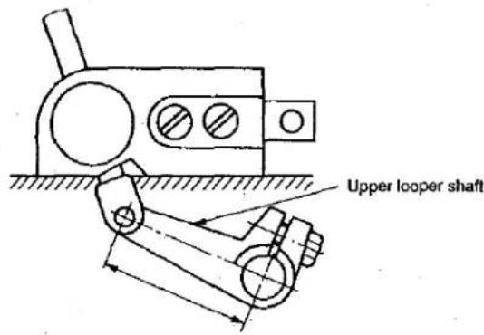
text_image
Upper looper shaftSP151 — 39 mm (1.535")
SP172 — 41 mm (1.614")
For models other than standard
| Model | Center-to-center |
| SP151HSP161HSP161S800M032SP161S800M040 | 39 (1.535") |
| SP161S800M048CSP161S900M032CSP161S900M040CSP161S900M048CSP172S | 41 (1.614") |
(4) Caution in assembly
1) Application of sealant
① Bottom surface of the upper looper guide support (Three-bond TB1102) Apply the sealant to the bottom surface of the upper looper guide support, which contacts with the frame surface.
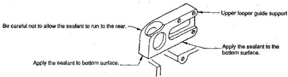
text_image
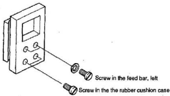
Be careful not to allow the sealant to run to the rear. Upper looper guide support Apply the sealant to the bottom surface. Apply the sealant to bottom surface.② Apply sealing compound (THREE BOND TB 1104) to four screws, i.e., two screws in the rubber cushion case and two screws in the feed bar.
text_image
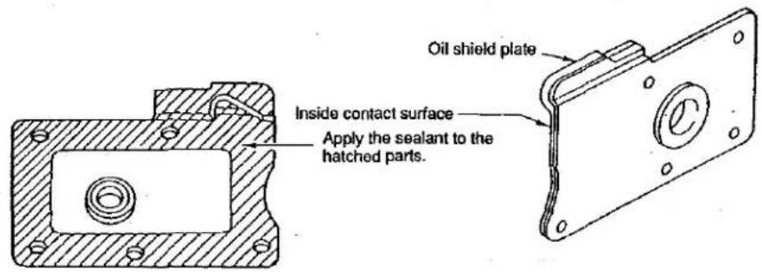
Screw in the feed bar, left Screw in the rubber cushion case③ Oil shield plate assembly (THREE BOND TB 1104) Apply the sealant to the inside of the oil shield plate.
text_image
Oil shield plate Inside contact surface Apply the sealant to the hatched parts.④ Feed cover packings (THREE BOND 1212) Fit feed cover packings A and B in the feed cover. Apply sealing compound (THREE BOND 1212) to the packings.

text_image
Feed cover Feed cover packing A Feed cover packing B2) Precautions to be taken with respect to the lubricating components
① Feed bar components
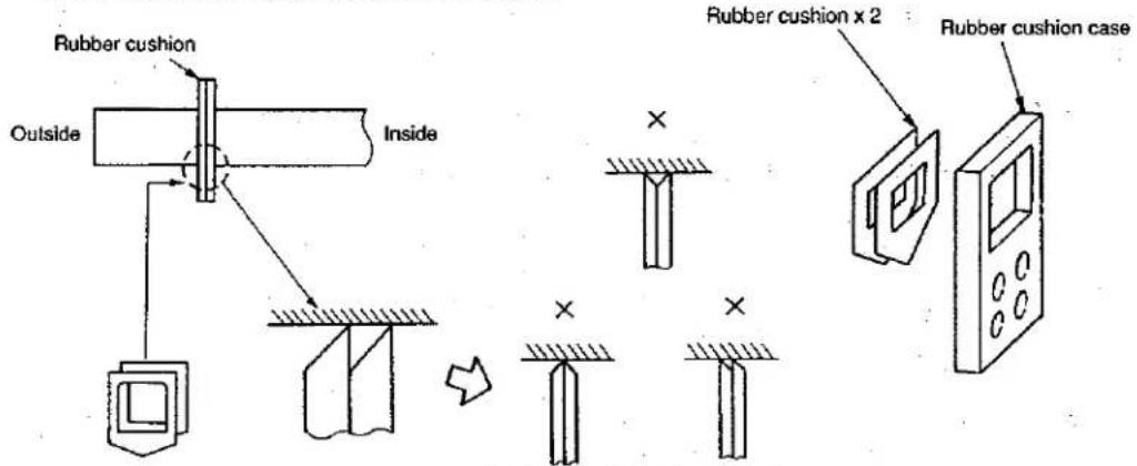
- Carefully check the orientation of the rubber cushion.
text_image
Rubber cushion Outside Inside Rubber cushion x 2 Rubber cushion case* If the oil shield rubber pieces are assembled as illustrated above, oil leakage will result. So, carefully assemble them.
② Upper looper guide components
- Cut both ends of the oil wick inside the upper looper connecting pin so that they are flush with the pin ends taking care not to allow the oil wick ends to protrude the pin ends.
Oil is fed to the upper looper lubricating felt through the oil wicks installed inside the frame. The oil wicks should not be longer than the required length.
So, carefully check the oil wick length.
One oil wick should be 10 (0.394") mm from the inside of the frame. The turned-up section of the oil wick should be flush with the frame end. Another oil wick should come in contact with the lubricating felt.
- Set the upper looper lubricating felt so that it projects 4 mm from the upper looper guide support as illustrated in the figure and confirm that the upper looper bracket comes in contact with the top of the felt.

text_image
Upper looper bracket Frame Upper looper bracket lubricating oil wick Approx. 10 mm (0.394") (Inside the frame) The upper looper bracket must come in contact with the upper looper lubricating felt. The oil wick should be almost flush with the frame.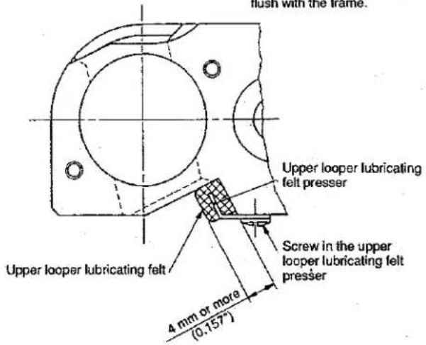
text_image
flush with the frame. Upper looper lubricating felt presser Screw in the upper looper lubricating felt presser Upper looper lubricating felt 4 mm or more (0.157°)(5) Kinds of motor pulleys, belts and frame support plate bolts
1) Motor pulleys and belts (for SP type machines)
| Sewing speed of sewing machine (s.p.m.) | 50Hz | 60Hz | ||||
| Outside diameter of motor pulley (mm) | Semi-sunken type (inch) | Fully-sunken type (inch) | Outside diameter of motor pulley (mm) | Semi-sunken type (inch) | Fully-sunken type (inch) | |
| 8500 | 160.5 (6.319") | 40 | 36 | 135.5 (5.335") | 38 | 34 |
| 8000 | 150.5 (5.925") | 40 | 34 | 125.5 (4.941") | 38 | 32 |
| 7500 | 140.5 (5.531") | 38 | 34 | 120.5 (4.744") | 38 | 32 |
| 7000 | 130.5 (5.138") | 38 | 34 | 110.5 (4.350") | 36 | 32 |
| 6500 | 120.5 (4.744"). | 38 | 32 | 100.5 (3.957") | 36 | 32 |
| 6000 | 110.5 (4.350") | 36 | 32 | 95.5 (3.563") | 35 | 30 |
| 5500 | 100.5 (3.957") | 36 | 32 | 85.5 (3.366") | 35 | 30 |
| 5000 | 90.5 (3.563") | 35 | 30 | 80.5 (3.169") | 34 | 30 |
| 4500 | 85.5 (3.366") | 35 | 30 | 70.5 (2.776") | 34 | 30 |
| 4000 | 75.5 (2.972") | 34 | 30 | 60.5 (2.382") | 34 | 29 |
* Use a motor of 3/4 HP (550 W) when the sewing machine runs at 7,500 s.p.m or higher speed.
Use a motor of 1/2 HP (400 W) when the sewing machine runs at a speed lower than 7,500 s.p.m.
o Be sure to use the motor of which speed does not exceed the sewing speed of the sewing machine.
* Part No. of motor pulley
| MTKP0XXX000 | (Enter the effective diameter to "XXX.")If the outside diameter of the motor pulley is 150.5 mm, enter "145" to "XXX". So, the part No. will be MTKP0145000.If the outside diameter of the motor pulley is 90.5 mm, enter "085" to "XXX". So, the part No. will be MTKP0085000. |
* Part No. of belt
| MTJVM00XX00 | (Enter a number that shows the belt length to "XX.") |
| If the belt length is 40 inches, enter "40" to "XX." So, the part No. will be MTJVM004000. | |
| If the belt length is 35 inches, enter "35" to "XX." So, the part No. will be MTJVM003500. |
2) Pat No. of frame support plate bolt
② Semi-sunken type frame support plate (A) asm. requires four bolts.
Support plate bolt (A) asm. 119-66751
| Support plate bolt (A) | 119-66702 x 1 |
| Locknut | NS6240630SN x 1 |
| Washer | WP1102016SC x 1 |
| Spring washer | WS1002560KR x 1 |
Separately from the aforementioned bolts, support plate (B) (115-71700) is available.
Difference of support plate bolts (A) and (B)
Entire length under the neck and length of threaded part
| Entire length (mm) | Length of threaded part (mm) | |
| Bolt (A) | 69 (2.717") | 39 (1.535") |
| Bolt (B) | 125 (4.921") | 95 (3.740") |

bar
| Year | Value | |---|---| | 2018 | 1.0 | | 2019 | 1.0 | | 2020 | 1.0 | | 2021 | 1.0 | | 2022 | 1.0 | | 2023 | 1.0 |- AMOUNTMENT OF THE LEVELS (MAY) AND WELL-TIME (Y: 105 - VALUE)
| Needle height | 1-needle overlock machine 2-needle overlock machine   | Classification | DescriptionSubclass | Needle height | Upper loop components | Lower loop components | ||||||
| 1-needle2-needle (left)A B | 2-needle (right)C | Upper looperheightD | Projection ofupper looperE | Height of plasmaF | Position ofgrade supportG | Center-to-centerof looper holderH | Remaining amountof lower looperI | Radius of lowerlooperJ | ||||
| 1-needle overlock machine | SP1S1HSP161HSP161S800M032SP161S800M040 | 10(0.394") | — | 10.7(0.421") | 4(0.157") | 44.35(1.766") | 7(0.276") | 39(1.535") | 4(0.157") | 67.4(2.654") | ||
| Upper loop components | 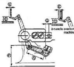 | SP161S800M048CCSP161S900M032CCSP161S900M040C | 10.5(0.413") | — | 10.9(0.429") | 4.4(0.173") | 47.15(1.856") | 7(0.276") | 41(1.614") | 3.6(0.142") | 67.4(2.654") | |
| SP161S900M048C | 11(0.433") | — | 11(0.433") | 4.8(0.189") | 48.15(1.896") | 6.5(0.256") | 41(1.614") | 4(0.157") | 67.4(2.654") | |||
| Lower loop components |  machine machine | 2 needle overlock machine | SP172S800MSP172S900M | 10.5(0.413") | 9.1(0.358") | 10.9(0.429") | 4.4(0.173") | 47.15(1.856") | 7(0.276") | 41(1.614") | 3.6(0.142") | 67.4(2.654") |
| SP172S900H | 11(0.433") | 9.6(0.378") | 11(0.433") | 4.8(0.173") | 48.15(1.896") | 6.5(0.256") | 41(1.614") | 4(0.157") | 67.4(2.654") | |||


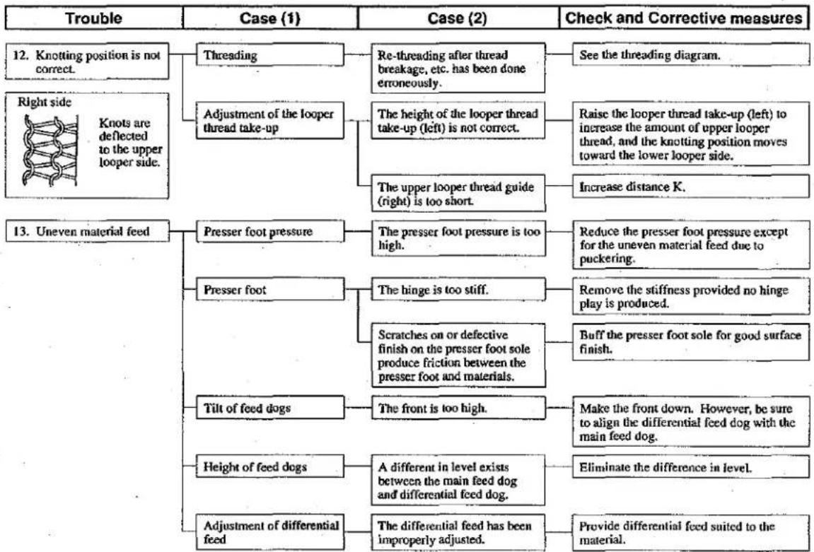
| Trouble | Case (1) | Case (2) | Check and Corrective measures |
| 1. Needle thread breakage | Threading | The thread is entangled with the thread guide, or the machine head has been incorrectly threaded. | Refer to the threading diagram. |
| Thread path | If needle hole area and pawl of throat plate, stitch tongue, lower looper, needle thread take-up lever, needle thread presser plate, thread guide or tension disk have scratches, burrs and rust, a resistance will result. | Remove such scratches, burrs, etc. and perform thread path finishing. Replace major components such as looper, which have been deformed, causing thread breakage. | |
| Needle guard | The needle hits the needle guard intensely, and sharp edges are produced on them, causing thread breakage. | Replace the needle and needle guard if they have worn. | |
| Needle | The needle is too thin for the thread. | Replace the needle by a proper one. | |
| Needle heat | The needle gets very hot, depending on the type of materials, number of plies and sewing speed, and causes the thread to burn and break. | Use a thinner needle. Reduce the sewing speed. Use the needle cooler. Use an S-point needle or needle for synthetic thread. | |
| Thread | The thread is weak because of its poor quality. | Replace the thread by one with good quality. | |
| Thread tension | The thread tension is too high. | Lower the thread tension. Check whether the needle thread guide goes too far resulting in a higher thread tension. | |
| Contact | The lower looper has been improperly positioned and strikes the feed dog or throat plate. | Properly position the double chain looper or lower looper. | |
| Threading | The thread is entangled with the thread guide, or the looper has been incorrectly threaded. | Refer to the threading diagram. | |
| 2. Looper thread breakage | Thread path | Scratches, burrs, rust, etc. on the pawl of the throat plate, stitch tongue, looper, looper thread take-up, thread guide, or tension discs causes friction. | Remove such scratches, burrs, etc. and carry out thread path finishing. Replace loopers or other components which have been deformed, causing thread breakage. |
| Adjustment of the looper thread take-up | The looper thread take-up or thread guide has been improperly positioned, causing excessive thread tension. | Refer to the pertinent Standard Adjustment. | |
| Thread tension | The looper thread tension is too high. | Reduce the tension while checking the tension balance other looper thread. | |
| Thread | The thread is weak because of its poor quality. | Replace the thread by one with good quality. | |
| Position of the thread guides. | The upper looper thread guide is too high, and the thread taking balance is disturbed, resulting in the thread breakage. | Refer to the pertinent Standard Adjustment. | |
| Needle heat | The needle gets hot, and the looper thread breaks when it comes in contact with the hot needle at the time of needle stop. | Refer to the clause relating to the needle heat causing needle thread breakage. | |
| 3. Needle breakage | Needle entry point | The needle entry has not been correctly adjusted, and the needle strikes the throat plate or presser foot. | Correct the needle entry. |
| Upper looper position | The upper looper juts out too much or it is too low. | Refer to the related Standard Adjustment. | |
| Contact with the looper | The needle strikes the looper, resulting in needle breakage. | Adjust the looper so that the looper does not come in contact with the needle. | |
| Needle guards | A needle guard has been improperly positioned, causing the needle point to strike it. | Refer to the pertinent Standard Adjustment. | |
| Needle count | The needle is too thin for the materials. | Replace the needle with a thicker one. | |
| Thread tension | The thread tension is too high. | Reduce the thread tension. | |
| Height of the feed dog or needle | The feed dog is too high, or the needle is too low, causing the needle to deflect with resultant needle breakage. | Refer to the related Standard Adjustment. | |
| 4. Overlocking needle thread stitches are skipped. | Lower looper | The blade point has defective shape and does not catch needle thread loops. | Replace the lower looper. |
| The lower looper fails to catch needle thread loops. Right side Wrong side | The clearance or the amount of return is not correct. | Refer to the relevant Standard Adjustment. | |
| Adjustment of the loopers. | Presser plate which presses the needle thread fails to move smoothly. In this case, loops fail to be made with consistency. | If the needle thread presser has been deformed by correction or the like, replace it with a new one. | |
| Needle thread presser | |||
| Needle | The needle is bent or improperly oriented. A needle or DC x I is used. | Replace the bent needle. Correctly orient and attach the needle DC x 27. Use a DC x J27 needle for a stretchy thread. | |
| Needle guards | Incorrect height or clearance prohibits correct guide for the needle. If a needle guard is too high, loops are crushed with consequent stitch skipping. | Refer to the pertinent Standard Adjustment. | |
| Height of needle | The needle has incorrect height and does not properly catch up loops even if the looper has a correct return. | Refer to the related Standard Adjustment. | |
| Needle heat | Stitch skipping occurs before the thread breaks due to needle heat. | Refer to the clause relating to the needle thread breakage due to needle heat. | |
| Positioning of the needle thread guide. | If the needle thread guide has been installed at the position beyond the correct position, thread take-up amount will be excessive, making small thread loops. | Refer to the pertinent Standard Adjustment. | |
| Threading | The thread has been entangled with a thread guide. Threading has not been correctly done. | See the threading diagram. | |
| 5. Lower looper stitches are skipped. The upper looper does not catch the lower looper thread. Right side Wrong side Right side Upper looper | Upper looper | The blade point has a bad shape, and fails to catch the loops. | Replace the upper looper with badly deformed blade point. |
| Lower looper | The clearance between the needle and the back of lower looper are not correct. | Replace the lower looper having a deformed tip. | |
| Adjustment of the loopers. | The feed amount of the lower looper, height of the upper looper, or clearance produced at time of crossing of the upper and lower loopers are not correct. | Refer to the relevant Standard Adjustment. | |
| Thread amount | Too much lower looper thread is fed, giving slack of thread. Slack of thread | Slightly lower the looper thread take-up (left) (reduction in distance J). | |
| Slightly raise the looper thread take-up (right) (increase in dimension O) to decrease the amount of thread. Lower the lower looper thread guide (increase in distance L), and decrease distance N to reduce the amount of thread. | |||
| Threading | The thread has been entangled with a thread guide. Threading has not been done correctly. | Refer to the threading diagram. | |
| Threading | The thread has been entangled with a thread guide. Threading has not been done correctly. | Refer to the threading diagram. | |
| Needle height | The needle, if positioned too high or low, may fail to catch the upper looper thread. | Refer to the related Standard Adjustment. | |
| Needle | The needle is bent or crushed in its point. | Replace the needle. At this time, be sure to eliminate the cause for such needle bend or needle point crush. | |
| Adjustment of the upper looper. | The height of the blade point is not correct, making the upper looper unable to properly pass the thread to the needle. The clearance between the needle and the back of the upper looper is not correct. | Refer to the relevant Standard Adjustment. | |
| Amount of thread | Excessive upper looper thread is fed, producing slack of thread. Slack of thread | Slightly lower the looper thread take-up (left) (to decrease J). Or shorten the upper looper thread guide (right) (to decrease K) to reduce the amount of thread. | |
| Slightly raise the looper thread take-up (right) (increase in distance O) to decrease the amount of thread. | |||
| If the thread tension is not enough, increase it. | |||
| 7. Overlocking chain-off thread is bad. (Provided that no chain-off trouble occurred when sewing operation was done with materials set on the machine.) | Position of the throat plate | The throat plate has been improperly positioned longitudinally, and chain-off thread gets in between the main feed dog and throat plate, causing defective chain-off thread. | Correct the position of the throat plate. |
| Feed dog | The auxiliary fee dog is too high, and interferes with chain-off thread. The auxiliary feed dog is too low. (Lower than the main feed dog by more than 0.5 mm) | Refer to the pertinent Standard Adjustment. | |
| The auxiliary feed dog has scratch | Repair or replace the auxiliary feed dog. | ||
| Adjustment of looper | Adjustment of loopers for producing chain-off thread requires higher accuracy as compared with the adjustment of them for sewing materials. | Refer to the relevant Standard Adjustment. | |
| Thread tension | The thread tension is too low. | Slightly increase the tension. | |
| The needle thread tension is too high, causing damaged balance with other thread tension. | Check whether the needle thread guide has been improperly positioned (too far) and needle thread tension has become too high. | ||
| 8. Overlocking needle thread is loose. | Position of the needle thread take-up guide and needle thread guide. | They are positioned too high, and the thread take-up draws out excessive needle thread. | Refer to the pertinent Standard Adjustment. |
| Thread tension | The thread tension balance has been disturbed. | Refer to the Standard Adjustment for the looper thread take-up components, and increase the tension if necessary. | |
| Needle | The needle is too thin for the thread used. | Replace it with a proper one. | |
| 9. Uneven overlocking stitches The knotting position of the upper and lower threads varies as shown below. | Looper thread tension | The upper and lower looper thread tensions are not enough. | Slightly increase the upper and lower looper thread tensions. |
| Looper thread take-up | The looper thread take-up (left) is too high. | Slightly lower the looper thread take-up (left) | |
| Knife width | The knife width is unsuited for the overedging width. | Make the overedging width slightly smaller than that given for the knife width. | |
| Thread path | Scratches on the thread path catch thread. | Check the thread path for scratches. | |
| Presser foot | The presser foot comes into contact unevenly with the throat plate and food dogs and tends to meander. | Make the presser foot come into contact with them evenly. | |
| Thread stand | Thread is not smoothly fed. | Adjust the thread stand so that the thread is fed smoothly. | |
| 10. The looper thread bulges out | Knife width | The knife width is too small for the overedging width. | Adjust the knife blade width to the normal value. |
| Looper thread take-up adjustment | The looper thread take-up draws out excessive looper thread. | Raise the looper thread take-up (right) (increase in distance O) | |
| 11. Looper thread bite | Knife width | The knife width is too large for the overedging width. | Use a knife having width suited to the overedging width. |
| Adjustment of the looper thread take-up | The looper thread take-up draws out insufficient amount of looper thread. | Lower the looper thread take-up (right) (reduction in distance O) |
flowchart
graph TD
    A["Trouble"] --> B["Case (1)"]
    B --> C["Threading"]
    B --> D["Adjustment of the looper thread take-up"]
    B --> E["Presser foot pressure"]
    B --> F["Presser foot"]
    B --> G["Tilt of feed dogs"]
    B --> H["Height of feed dogs"]
    B --> I["Adjustment of differential feed"]

    C --> J["Re-threading after thread breakage, etc. has been done erroneously."]
    D --> K["The height of the looper thread take-up (left) is not correct."]
    D --> L["The upper looper thread guide (right) is too short."]
    J --> M["See the threading diagram."]
    K --> N["Raise the looper thread take-up (left) to increase the amount of upper looper thread, and the knotting position moves toward the lower looper side."]
    L --> O["Increase distance K."]
    M --> P["Reduce the presser foot pressure except for the uneven material feed due to puckering."]
    N --> Q["Remove the stiffness provided no hinge play is produced."]
    O --> R["Buff the presser foot sole for good surface finish."]
    P --> S["Make the front down. However, be sure to align the differential feed dog with the main feed dog."]
    Q --> T["Eliminate the difference in level."]
    R --> U["Provide differential feed suited to the material."]
    S --> V["A different in level exists between the main feed dog and differential feed dog."]
    T --> W["The differential feed has been improperly adjusted."]

section Y/Y and section Y/Y
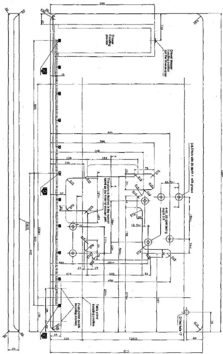
Detailed dimensions of section WW, section ZZ.
(Note) All different numbers are
COSPEECE 144-95 ON AED
text_image
3-8.5 hio wh 25 daohi 1 wdi goove Drawer stacker (on the reverse side) Drawer stacker (using passion on the reverse side) 109 100 Driver visibing position 4-10.20 goy laiding depth 2.5 6/3 6/2 6/1 5/1 5/0 4/0 3/0 2/0 1/0 0/0 9/0 8/0 7/0 6/0 5/0 4/0 3/0 2/0 1/0 0/0 9/0 8/0 7/0 6/0 5/0 4/0 3/0 2/0 1/0 0/0 9/0 8/0 7/0 6/0 5/0 4/0 3/0 2/0 1/1 0/0 9/0 8/0 7/0 6/0 5/0 4/0 3/0 2/0 1/1 0/0 9/0 8/0 7/0 6/0 5/0 4/0 3/0 2/0 1/1 0/0 9/0 8/0 7/0 6/1
(1) Semi-sunken type
1. Dimensions of Label (semi-sunken type)
inch → mm CONVERSION TABLE
1"=25.4mm
| inch | 0" | 1" | 2" | 3" | 4" | 5" | 6" | 7" | 8" | ||
| 0 | 25.4 | 50.8 | 76.2 | 101.6 | 127 | 152.4 | 177.8 | 203.2 | |||
| 1/64 | 015625 | 0.3969 | 25.7969 | 51.1969 | 76.5969 | 101.9969 | 127.3969 | 152.7969 | 178.1969 | 203.5069 | |
| 1/32 | 03125 | 0.7938 | 26.1938 | 51.5938 | 76.9938 | 102.3938 | 127.7938 | 153.1938 | 178.5938 | 203.9938 | |
| 3/64 | 046875 | 1.1906 | 26.5906 | 51.9906 | 77.3906 | 102.7906 | 128.1906 | 153.5906 | 178.9906 | 204.3906 | |
| 1/16 | 0625 | 1.5875 | 26.9875 | 52.3875 | 77.7875 | 103.1875 | 128.5875 | 153.9875 | 179.3875 | 204.7875 | |
| 5/64 | 078125 | 1.9844 | 27.3844 | 52.7844 | 78.1844 | 103.5844 | 128.9844 | 154.3844 | 179.7844 | 205.1844 | |
| 3/32 | 09375 | 2.3812 | 27.7812 | 53.1812 | 78.5812 | 103.9812 | 129.3812 | 154.7812 | 180.1812 | 205.5812 | |
| 7/64 | 109375 | 2.7781 | 28.1781 | 53.5781 | 78.9781 | 104.3781 | 129.7781 | 155.1781 | 180.5781 | 205.9781 | |
| 1/8 | 125 | 3.175 | 28.575 | 53.975 | 79.3750 | 104.775 | 130.175 | 155.5750 | 180.975 | 206.375 | |
| 9/64 | 140625 | 3.5719 | 28.9719 | 54.3719 | 79.7719 | 105.1719 | 130.5719 | 155.9719 | 181.3719 | 206.7719 | |
| 5/32 | 15625 | 3.9688 | 29.3688 | 54.7688 | 80.1688 | 105.5688 | 130.9688 | 156.3688 | 181.7688 | 207.1688 | |
| 11/64 | 171875 | 4.3656 | 29.7656 | 55.1656 | 80.5656 | 105.9656 | 131.3656 | 156.7656 | 182.1656 | 207.5656 | |
| 3/16 | 1875 | 4.7625 | 30.1625 | 55.5625 | 80.9625 | 106.3625 | 131.7625 | 157.1625 | 182.5625 | 207.9625 | |
| 13/64 | 203125 | 5.1594 | 30.5594 | 55.9594 | 81.3594 | 106.7594 | 132.1594 | 157.5594 | 182.9594 | 208.3594 | |
| 7/32 | 21875 | 5.5562 | 30.9562 | 56.3562 | 81.7562 | 107.1562 | 132.5562 | 157.9562 | 183.3562 | 208.7562 | |
| 15/64 | 234375 | 5.9531 | 31.3531 | 56.7531 | 82.1531 | 107.5531 | 132.9531 | 158.3531 | 183.7531 | 209.1531 | |
| 1/4 | 25 | 6.35 | 31.75 | 57.15 | 82.55 | 107.95 | 133.35 | 158.75 | 184.15 | 209.55 | |
| 17/64 | 265625 | 6.7469 | 32.1469 | 57.5469 | 82.9469 | 108.3469 | 133.7469 | 159.1469 | 184.5469 | 209.9469 | |
| 9/32 | 28125 | 7.1438 | 32.5438 | 57.9438 | 83.3438 | 108.7438 | 134.1438 | 159.5438 | 184.9438 | 210.3438 | |
| 19/64 | 296875 | 7.5406 | 32.9406 | 58.3406 | 83.7406 | 109.1406 | 134.5406 | 159.9406 | 185.3406 | 210.7406 | |
| 5/16 | 3125 | 7.9375 | 33.3375 | 58.7375 | 84.1375 | 109.5375 | 134.9375 | 160.3375 | 185.7375 | 211.1375 | |
| 21/64 | 328125 | 8.3344 | 33.7344 | 59.1344 | 84.5344 | 109.9344 | 135.3344 | 160.7344 | 186.1344 | 211.5344 | |
| 11/32 | 34375 | 8.7312 | 34.1312 | 59.5312 | 84.9312 | 110.3312 | 135.7312 | 161.1312 | 186.5312 | 211.9312 | |
| 23/64 | 359375 | 9.1281 | 34.5281 | 59.9281 | 85.3281 | 110.7281 | 136.1281 | 161.5281 | 186.9281 | 212.3281 | |
| 3/8 | 375 | 9.525 | 34.925 | 60.325 | 85.725 | 111.125 | 136.525 | 161.925 | 187.325 | 212.725 | |
| 25/64 | 390 625 | 9.9219 | 35.3219 | 60.7219 | 86.1219 | 111.5219 | 136.9219 | 162.3219 | 187.7219 | 213.1219 | |
| 13/32 | 40625 | 10.3188 | 35.7188 | 61.1188 | 86.5188 | 111.9188 | 137.3188 | 162.7188 | 188.1188 | 213.5188 | |
| 27/64 | 421875 | 10.7156 | 36.1151 | 61.5156 | 86.9156 | 112.3156 | 137.7156 | 163.1156 | 188.5156 | 213.9156 | |
| 7/16 | 4375 | 11.1125 | 36.5125 | 61.9125 | 87.3125 | 112.7125 | 138.1125 | 163.5125 | 188.9125 | 214.3125 | |
| 29/64 | 453125 | 11.5094 | 36.9094 | 62.3094 | 87.7094 | 113.1094 | 138.5094 | 163.9094 | 189.3094 | 214.7094 | |
| 15/32 | 46875 | 11.9062 | 37.3062 | 62.7062 | 88.1062 | 113.5062 | 138.9062 | 164.3062 | 189.7062 | 215.1062 | |
| 31/64 | 484375 | 12.3031 | 37.7031 | 63.1031 | 88.5031 | 113.9031 | 139.3031 | 164.7031 | 190.1031 | 215.5031 | |
| 1/2 | 5 | 12.7 | 38.1 | 63.5 | 88.9 | 114.3 | 139.7 | 165.1 | 190.5 | 215.9 | |
| 33/64 | 515625 | 13.0969 | 38.4969 | 63.8969 | 89.2969 | 114.6969 | 140.0969 | 165.4969 | 190.8969 | 216.2969 | |
| 17/32 | 53125 | 13.4938 | 38.8938 | 64.2938 | 89.6938 | 115.0938 | 140.4938 | 165.8938 | 191.2938 | 216.6938 | |
| 35/64 | 546875 | 13.8906 | 39.2906 | 64.6906 | 90.0906 | 115.4906 | 140.8906 | 166.2906 | 191.6906 | 217.0906 | |
| 9/16 | 5625 | 14.2875 | 39.6875 | 65.0875 | 90.4875 | 115.8875 | 141.2875 | 166.6875 | 192.0875 | 217.4875 | |
| 37/64 | 578125 | 14.6844 | 40.0844 | 65.4844 | 90.8844 | 116.2844 | 141.6844 | 167.0844 | 192.4844 | 217.8844 | |
| 19/32 | 59375 | 15.0812 | 40.4812 | 65.8812 | 91.2812 | 116.6812 | 142.0812 | 167.4812 | 192.8812 | 218.2812 | |
| 39/64 | 609375 | 15.4781 | 40.8781 | 66.2781 | 91.6781 | 117.0781 | 142.4781 | 167.8781 | 193.2781 | 218.6781 | |
| 5/8 | 625 | 15.875 | 41.275 | 66.675 | 92.075 | 117.475 | 142.875 | 168.275 | 193.675 | 219.075 | |
| 41/64 | 640625 | 16.2719 | 41.6719 | 67.0719 | 92.4719 | 117.8719 | 143.2719 | 168.6719 | 194.0719 | 219.4719 | |
| 21/32 | 65625 | 16.6688 | 42.0688 | 67.4688 | 92.8688 | 118.2688 | 143.6688 | 169.0688 | 194.4688 | 219.8688 | |
| 43/64 | 671875 | 17.0656 | 42.4656 | 67.8656 | 93.2656 | 118.6656 | 144.0656 | 169.4656 | 194.8656 | 220.2656 | |
| 11/16 | 6875 | 17.4625 | 42.8625 | 68.2625 | 93.6625 | 119.0625 | 144.4625 | 169.8625 | 195.2625 | 220.6625 | |
| 45/64 | 703125 | 17.8594 | 43.2594 | 68.6594 | 94.0594 | 119.4594 | 144.8594 | 170.2594 | 195.6594 | 221.0594 | |
| 23/32 | 71875 | 18.2562 | 43.6562 | 69.0562 | 94.4562 | 119.8562 | 145.2562 | 170.6562 | 196.0562 | 221.4562 | |
| 47/64 | 734375 | 18.6531 | 44.0531 | 69.4531 | 94.8531 | 120.2531 | 145.6531 | 171.0531 | 196.4531 | 221.8531 | |
| 3/4 | 75 | 19.05 | 44.45 | 69.85 | 95.25 | 120.65 | 146.05 | 171.45 | 196.85 | 222.25 | |
| 49/64 | 765625 | 19.4469 | 44.8469 | 70.2469 | 95.6469 | 121.0469 | 146.4469 | 171.8469 | 197.2469 | 222.6469 | |
| 25/32 | 78125 | 19.8438 | 45.2438 | 70.6438 | 96.0438 | 121.4438 | 146.8438 | 172.2438 | 197.6438 | 223.0438 | |
| 51/64 | 796875 | 20.2406 | 45.6406 | 71.0406 | 96.4406 | 121.8406 | 147.2406 | 172.6406 | 198.0406 | 223.4406 | |
| 13/16 | 8125 | 20.6375 | 46.0375 | 71.4375 | 96.8375 | 122.2375 | 147.6375 | 173.0375 | 198.4375 | 223.8375 | |
| 53/64 | 728125 | 21.0344 | 46.4344 | 71.8344 | 97.2344 | 122.6344 | 148.0344 | 173.4344 | 198.8344 | 224.2344 | |
| 27/32 | 84375 | 21.4312 | 46.8312 | 72.2312 | 97.6312 | 123.0312 | 148.4312 | 173.8312 | 199.2312 | 224.6312 | |
| 55/64 | 859375 | 21.8281 | 47.2281 | 72.6281 | 98.0281 | 123.4281 | 148.8281 | 174.2281 | 199.6281 | 225.0281 | |
| 7/8 | 875 | 22.225 | 47.625 | 73.025 | 98.425 | 123.825 | 149.225 | 174.625 | 200.025 | 225.425 | |
| 57/64 | 890625 | 22.6219 | 48.0219 | 73.4219 | 98.8219 | 124.2219 | 149.6219 | 175.0219 | 200.4219 | 225.8219 | |
| 29/32 | 90625 | 23.0188 | 48.4188 | 73.8188 | 99.2188 | 124.6188 | 150.0188 | 175.4188 | 200.8188 | 226.2188 | |
| 59/64 | 921875 | 23.4156 | 48.8156 | 74.2156 | 99.6156 | 125.0156 | 150.4156 | 175.8156 | 201.2156 | 226.6156 | |
| 15/16 | 9375 | 23.8125 | 49.2125 | 74.6125 | 100.0125 | 125.4125 | 150.8125 | 176.2125 | 201.6125 | 227.0125 | |
| 61/64 | 953125 | 24.2094 | 49.6094 | 75.0094 | 100.4094 | 125.8094 | 151.2094 | 176.6094 | 202.0094 | 227.4094 | |
| 31/32 | 96875 | 24.6062 | 50.0062 | 75.4062 | 100.8062 | 126.2062 | 151.6062 | 177.0062 | 202.4062 | 227.8062 | |
| 63/64 | 984375 | 25.0031 | 50.4031 | 75.8031 | 101.2031 | 126.6031 | 152.0031 | 177.4031 | 202.8031 | 228.2031 | |