39500JL - Sewing machine Union Special - Free user manual and instructions
Find the device manual for free 39500JL Union Special in PDF.

User questions about 39500JL Union Special
0 question about this device. Answer the ones you know or ask your own.
Ask a new question about this device
Download the instructions for your Sewing machine in PDF format for free! Find your manual 39500JL - Union Special and take your electronic device back in hand. On this page are published all the documents necessary for the use of your device. 39500JL by Union Special.
USER MANUAL 39500JL Union Special
natural_image
Black-and-white illustration of a Union Special industrial machine with visible internal components and no readable text or symbols.CLASS 39500
HI-STYLED HIGH SPEED
DIFFERENTIAL FEED OVERSEAMERS
FOR USE WITH
DETEXOMAT AUTOMATIC HOSIERY UNITS
UnionSpecial MACHINE COMPANY
CHICAGO
Catalog No. 103 JK
(Supplement to Catalog No. 103 FA)
INSTRUCTIONS
FOR
ADJUSTING AND OPERATING
LIST OF PARTS
CLASS 39500
Styles
39500 JK
39500 JL
First Edition
Copyright 1968
By
Union Special Machine Co.
Rights Reserved in All Countries
UnionSpecial
MACHINE COMPANY
INDUSTRIAL SEWING MACHINES
CHICAGO
March, 1968
Printed in U.S.A.
IDENTIFICATION OF MACHINES
Each Union Special machine is identified by a Style number on a name plate on the machine. Style numbers are classified as standard and special. Standard Style numbers have one or more letters suffixed, but never contain the letter "Z". Example: "Style 39500 JK". Special Style numbers contain the letter "Z". When only minor changes are made in a standard machine, a "Z" is suffixed to the standard Style number. Example: "Style 39500 JKZ".
Styles of machines similar in construction are grouped under a Class number, which differs from the Style number in that it contains no letters. Example: "Class 39500".
APPLICATION OF CATALOG
This catalog is a supplement to Catalog No. 103 FA and should be used in conjunction therewith. Only those parts used on Styles 39500 JK and JL, but not on Style 39500 FA are illustrated and listed at the back of this catalog. On the page opposite the illustration will be found a listing of the parts, with their part numbers, description and the number of pieces required. Numbers in the first column are reference numbers only, and merely indicate the position of that part in the illustration, Reference numbers should never be used in ordering parts. Always use the part number listed in the second column.
This catalog applies specifically to the standard Style of machine as listed herein. It can also be applied with discretion to some Special Styles of machines in Class 39500. References to directions, such as right, left, front, back, etc., are given from the operator's position while seated at the machine. Operating direction of handwheel is away from operator.
STYLES OF MACHINES
Hi-Styled High Speed, One or Two Curved Blade Needles, Two Looper or One Looper-One Spreader Three Thread Overseaming Machine, Prepared for Use With Detexomat Automatic Hosiery Unit. Differential Feed, Trimming Mechanism with Spring Pressed Lower Knife, Automatic Lubricating System.
39500 JK Single needle, two looper, three thread, light duty machine for closing the toe sections of women's seamless nylon hosiery. Seam specification 505-EFe-1 inverted. Standard seam width 1/16 to 3/32 inch depending on material. Stitch range 15-100 per inch. Cam adjusted main and differential feeds. Maximum recommended speed 7000 R.P.M.
39500 JL Two needle, one looper-one spreader, three thread, light duty machine for closing the toe sections of women's seamless nylon hosiery. Seam specification 521-SSa-1. Standard seam width approximately 1/8 inch from left needle. Stitch range 20-100 per inch. Cam adjusted main and differential feeds. Maximum recommended speed 7000 R.P.M.
OILING
CAUTION! Oil was drained from machine when shipped, so reservoir must be filled before beginning to operate. Oil capacity of Class 39500 is six ounces. A straight mineral oil of a Saybolt viscosity of 200 to 250 seconds at 100^ Fahrenheit should be used.
OILING (Continued)
Machine is filled with oil at spring cap in top cover. Oil level is checked at sight gauge on front of machine. Red bulb on oil level indicator should show between gauge lines when machine is stationary.
Machine is automatically lubricated. No oiling is necessary, other than keeping main reservoir filled. Check oil daily before the morning start; add oil as required.
The oil drain plug screw is located at back of machine near bottom edge of base. It is a magnetic screw designed to accumulate possible foreign materials which may have entered the crank case. It should be removed and cleaned periodically.
NEEDLES
Each Union Special needle has both type and size number. The type number denotes the kind of shank, point, length, groove, finish and other details. The size number, stamped on the needle shank, denotes largest diameter of blade, measured in thousandths of an inch, midway between shank and eye. Collectively, type and size number represent the complete symbol which is given on the label of all needles packaged and sold by Union Special.
Class 39500 machines use a curved blade needle. The standard needle for Style 39500 JK is Type 154 GAS; while the standard needle for Style 39500 JL is Type 154 GCS. Below are the type numbers, description and sizes available of the recommended needles.
Type No.
Description and Sizes
| 154 GAS | Round shank, round point, curved blade, standard length, single groove, struck groove, spotted, chromium plated and is available in sizes 022, 025, 027, 029, 032, 036, 040, 044, 049, 054. |
| 154 GCS | Slabbed shank, round point, .046 inch double slab, curved blade, standard length, double groove, struck groove, spotted, chromium plated and is available in sizes 022, 025, 027, 029, 032, 040. |
To have needle orders promptly and accurately filled, an empty package, a sample needle, or the type and size number should be forwarded. Use description on label. A complete order would read: "1000 Needles, Type 154 GAS, Size 027".
Selection of proper needle size is determined by size of thread used. Thread should pass freely through needle eye in order to produce a good stitch formation.
Success in the operation of Union Special machines can be secured only by use of needles packaged under our brand name, UnionSpecial, which is backed by a reputation for producing highest quality needles in materials and workmanship for more than three-quarters of a century.
CHANGING NEEDLES
Release pressure on presser foot by turning presser foot release bushing (AG, Fig. 1 or 1A) and swing presser arm (U) out of position. Turn handwheel in operating direction until needle is at its lowest point of travel. Using hexagonal socket wrench No. 21388 AU, furnished with machine, loosen needle clamp nut about 1/4 turn. Again turn handwheel until needle is at high position. Withdraw needle.
CHANGING NEEDLES (Continued)
To replace needle, leave needle holder at high position and, with the flat to the left, insert needle in holder until it rests against stop pin. Keeping needle in this position, turn handwheel until holder is again at its low point of travel; then tighten nut. Return presser arm (U) to position; re-lock presser foot release bushing (AG).
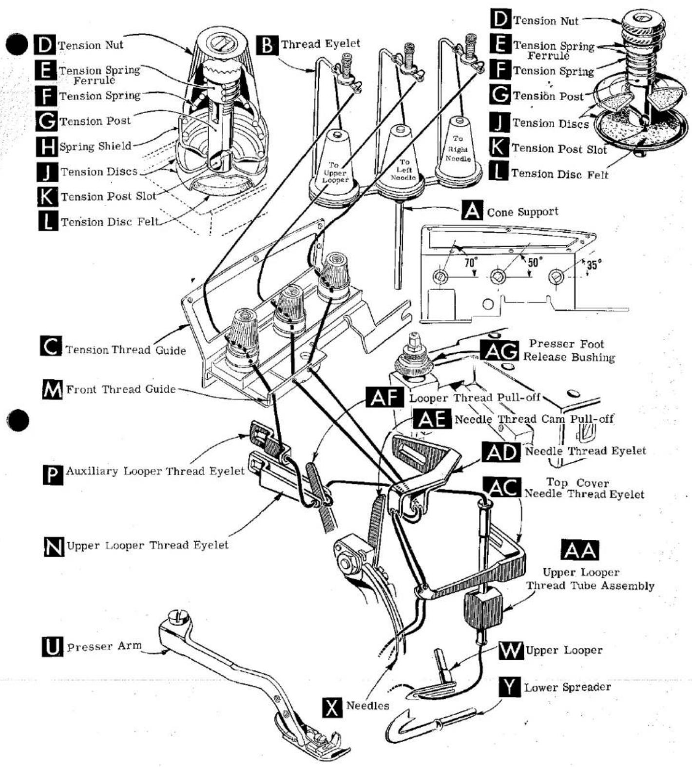
THREAD STAND
After thread comes from cones on cone support (A, Fig. 1 or 1A) it is brought up through the back hole of thread eyelet (B), then down through the front hole of thread eyelet. Next it is threaded through the upper hole of tension thread guide (C) from front to back and then through the lower hole from back to front.
NOTE: The lower looper thread on Style 39500 JK and the right needle thread on Style 39500 JL are threaded through the tension thread guide (C), first through the upper hole from back to front, second through the middle hole from front to back, and third through the lower hole back to front.
All threads then continue between the tension discs (J), through tension post slot (K) in tension post (G) and on through front thread guide (M).
THREADING
Only parts involved in threading are shown in threading diagram (Fig. 1 and 1A). Parts are placed in their relative positions for clarity.
It will simplify threading Style 39500 JK to follow recommended sequence of threading lower looper first, upper looper second, and needle third.
On Style 39500 JL follow the recommended sequence of threading the upper looper first, the right needle second and the left needle third. Complete the full threading of one before proceeding to the next one.
Before beginning to thread, swing cloth plate open, turn handwheel in operating direction until needle (X) is at high position. Release pressure on presser foot by turning presser foot release bushing (AG), and swing presser arm (U) out of position.
Be sure the threads, as they come from the tension thread guide (C) are between tension discs (J) and in tension post slot (K) in tension post (G). The tension posts should be positioned so the tension post slot will be at the approximate angle for the different threads as indicated in Fig. 1 and 1A.
TO THREAD LOWER LOOPER (39500 JK only)
Thread lower looper thread through right eyelet of front thread guide (M). Then double end of thread and lead it through both eyes of lower looper thread eyelet (R, Fig. 1) from right to left. Note: thread must pass in front of looper thread pull-off (AF). Lead thread behind fabric guard (S) and through eyelet hole of frame looper thread guide (T). Turn handwheel in operating direction until heel of lower looper (V) is all the way to the left; then thread through both eyes from left to right. Left eye of lower looper can be threaded easily if tweezers are in left hand.
TO THREAD UPPER LOOPER
Thread upper looper thread through left eyelet of front thread guide (M, Fig. 1 or 1A). Turn handwheel until point of upper looper (W) is all the way left. Lead

text_image
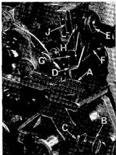
D Tension Nut E Tension Spring Ferrule F Tension Spring G Tension Post H Spring Shield J Tension Discs K Tension Post Slot L Tension Disc Felt B Thread Eyelet To Upper Looper, To Needle Lower Looper A Cone Support 70° 50° 35° C Tension Thread Guide M Front Thread Guide N Upper Looper Thread Eyelet P Auxiliary Looper Thread Eyelet R Lower Looper Thread Eyelet S Fabric Guard Bracket T Frame Looper Thread Guide U Presser Arm AG Presser Foot Release Bushing AF Looper Thread Pull-off AE Needle Thread Cam Pull-off AD Needle Thread Eyelet AC Top Cover Needle Thread Eyelet AA Upper Looper Thread Tube Assembly X Needle W Upper Looper V Lower LooperFig. 1
text_image
D Tension Nut E Tension Spring Ferrule F Tension Spring G Tension Post H Spring Shield J Tension Discs K Tension Post Slot L Tension Disc Felt B Thread Eyelet To Upper Looper To Left Noodles To Right Noodles D Tension Nut E Tension Spring Ferrule F Tension Spring G Tension Post J Tension Discs K Tension Post Slot L Tension Disc Felt A Cone Support 70° 50° 35° C Tension Thread Guide M Front Thread Guide P Auxiliary Looper Thread Eyelet N Upper Looper Thread Eyelet U Presser Arm X Needles AF Looper Thread Pull-off AE Needle Thread Cam Pull-off AD Needle Thread Eyelet AC Top Cover Needle Thread Eyelet AA Upper Looper Thread Tube Assembly W Upper Looper Y Lower SpreaderFig. 1A
TO THREAD UPPER LOOPER (Continued)
thread through auxiliary looper thread eyelet (P) from back to front, then through both eyes of upper looper thread eyelet (N) from left to right. NOTE: Thread must pass in front of looper thread pull-off (AF). After pulling up upper looper thread tube assembly (AA), lead the thread under neck of top cover casting and down through thread tube assembly (AA). Pull thread out bottom of tube, push tube down, and then insert thread through upper looper eye from front to back.
CAUTION! Be sure upper looper thread is under the needle threads when passing from tube assembly to upper looper eye.
TO THREAD THE NEEDLE (39500 JK only)
Thread needle thread through middle eyelet of front thread guide (M). Then turn handwheel in operating direction until needle (X, Fig. 1) is at its highest position. Insert needle thread from right to left, through both eyes of needle thread eyelet (AD), under neck of top cover casting; then down through hole in top cover needle thread eyelet (AC). Thread needle from front.
TO THREAD NEEDLES (39500 JL only)
Thread the right needle thread through the right eyelet of front thread guide (M, Fig. 1A) and thread the left needle thread through the middle eyelet of front thread guide. Then turn handwheel in operating direction until needles (X) are at their highest position. Insert both needle threads from right to left, through BOTH eyes of needle thread eyelet (AD), under neck of top cover casting and then down through holes in top cover needle thread eyelet (AC). The right needle thread should be threaded in the right hole and the left needle thread through the left hole of the top cover needle thread eyelet. Thread needles from the front.
THREAD TENSION
The amount of tension on needle and looper threads is regulated by the tension nuts (D, Fig. 1 and 1A). Tension on threads should be only enough to secure proper stitch formation.
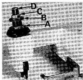
PRESSER FOOT PRESSURE
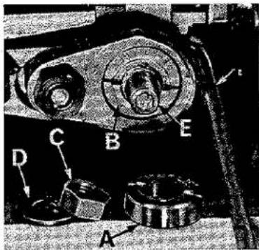
Sufficient presser foot pressure to feed work uniformly should be maintained. Should it be necessary to increase or decrease amount of pressure on presser foot, loosen lock nut (A, Fig. 2) and turn adjusting screw (B). Adjusting screw has a right hand thread so tightening increases pressure, loosening decreases pressure. When pressure adjusting screw (B) has been properly set, tighten lock nut (A). With presser foot resting on throat plate, position locking nut (C) so that its under surface is approximately 1/32 inch to 1/16 inch from the top surface of adjusting screw (B). Set cap (D) against locking nut (C).
text_image
A B C DFig. 2
FEED ECCENTRICS
Feed eccentrics used in Style 39500 JK machines have been selected to produce approximately 30 stitches per inch. On Style 39500 JL, the eccentrics have been selected to produce approximately 80 stitches per inch. It will be noted that the part number of main and differential feed eccentric is No. 39540 B-30 on Style 39500 JK. On Style 39500 JL the part number of the main feed eccentric is No. 39540 B-100, while that of the differential feed eccentric is No. 39540 B-70. Minor numbers of the part symbol indicate approximately the number of stitches obtainable when using that eccentric. Unless otherwise specified, machines will be shipped with the combination of eccentrics as outlined above.
Generally speaking, differential (right hand) feed eccentric determines number of stitches produced; main (left hand) feed eccentric is selected in relation to degree and direction of stretch of material being sewn, or type of operation.
Following stitch number feed eccentrics are available under No. 39540 B-4, -5, -6, -7, -8, -9, -10, -11, -12, -13, -14, -15, -16, -18, -20, -22, -24, -26, -28, -30, -32, -34, -36, -40, -50, -60, -70, -100. Only two eccentrics are supplied with each machine. Additional eccentrics may be ordered separately. To order an eccentric, use No. 39540 B with a minor number suffixed to indicate number of stitches desired. Example: "39540 B-30".
ASSEMBLING AND ADJUSTING SEWING PARTS
Before assembling and adjusting sewing parts, remove cloth plate, fabric guard, chip guard, upper knife assembly, lower knife holder assembly, then follow this suggested sequence:
NOTE: Adjusting instructions will pertain to all styles of machines covered in this catalog, unless otherwise specified.
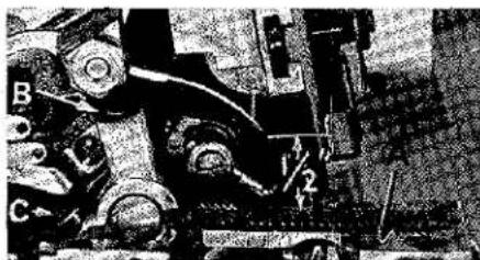
SETTING THE NEEDLE
natural_image
Close-up of a mechanical assembly with labeled parts (B and C), no readable text or symbols present.Fig. 3
With throat plate assembled in position, needle should center in the front end of needle slot. When needle is at high position, the needle point should be set 1/2 inch above the throat plate (A, Fig. 3) for Style 39500 JK. For Style 39500 JL the needles points should be 7/16 inch above the throat plate. To align needle or set the height above the throat plate, move needle driving arm (B) by loosening clamp screw (C). After needle has been properly set, tighten clamp screw and remove throat plate.
If needle thread cam pull-off (A, Fig. 4) overlaps looper thread pull-off (B), separate by moving looper thread pull-off back. When retightening looper pull-off screw, be sure to take up end play in needle driving arm.

text_image
A BFig. 4
SETTING THE NEEDLE (Continued)
text_image
A B C 1/8At this point, insert lower looper (A, Fig. 5) for Style 39500 JK or lower spreader (A, Fig. 5A) for Style 39500 JL, into bar (B). With lower looper or spreader at the left end of its stroke, set looper point 1/8 inch from center of needle (Fig. 5) or set lower spreader 1/8 inch to the left of the center-line of left needle (Fig. 5A), using looper gauge No. 21225 G-1/8. Do not have lower looper or spreader deflecting needle. Tighten nut (C). Now assemble differential (front) feed dog.
Fig. 5
SETTING THE REAR NEEDLE GUARD
Set rear needle guard (A, Fig. 6) as high as possible, without interfering with either lower looper or spreader, or movement of lower knife holder, but still in position to deflect needle forward .002-.004 inch. Screw (B) is used to set rear needle guard. Make sure there is no interference between rear needle guard and lower looper or spreader.
SETTING THE LOWER LOOPER OR SPREADER
text_image
A C B DNow finish lower looper or spreader adjustment. As lower looper or spreader moves to the right, its point should be set into the needle scarf (A, Fig. 7) until the needle springs forward from rear guard surface another .002-.004 inch.

text_image
A B CFig. 5A
SETTING THE FRONT NEEDLE GUARD
Assemble front needle guard (C, Fig. 6). When lower looper is springing needle off rear needle guard, set front needle guard as close as possible to needle without touching. Screw (D) is used to adjust and set front needle guard. After this setting make sure there is no interference between needle guards and differential feed dog.
Fig. 6
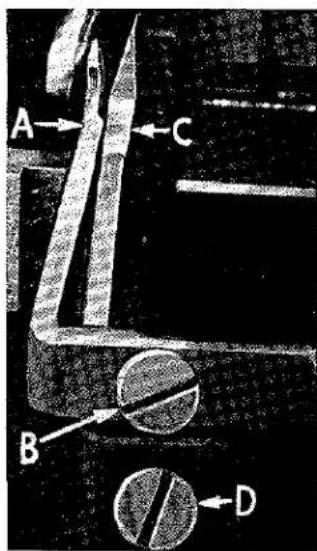
SETTING THE UPPER LOOPER
Insert upper looper (A, Fig. 8) in its holder. Screw (B, Fig. 8) holds upper looper in its holder, and permits it to be pushed in or out, or turned around its shank. Insert upper looper holder into upper looper shaft, if it is not already in place. Screw (C, Fig. 8) on clamp holds the upper looper holder in the shaft. Locate upper looper in its holder so that the shank extends 1/32 to 1/16 inch beyond holder (Fig. 8).

text_image
Technical diagram with labeled component 'A' and directional arrows, likely from an engineering or mechanical contextFig. 7
SETTING THE UPPER LOOPER (Continued)
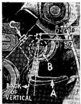
When the upper looper is at the right end of its stroke, upper looper holder should be set to position upper looper shank back of vertical (Fig. 8).
Be sure, there is a clearance between heel of looper and casting. By adjusting looper holder in or out of upper looper shaft and by turning the looper around its shank, set upper
looper point to cross lower looper to the left of the lower looper eye or spreader with 0.002 to 0.004 clearance (Fig. 9).
text_image
1 2 3 4 5 6 7 8 9 10 11 12 13 14 15 16 17 18 19 20 21 22 23 24 25 26 27 28 29 30 31 32 BACK OF VERTICALFig. 8

text_image
062 CLEARANCEAs the upper looper moves toward the top of its stroke, the heel of the upper looper should pass behind the lower looper head with 1/64 to 1/32 inch clearance. Fig. 8
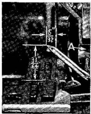
Next, turn handwheel until looper is at the left end of its travel; check dimensions of upper looper point with respect to needle and throat plate (Fig. 10). If resetting is necessary, do it by moving the upper looper holder (A, Fig. 10). Figure 10 represents the dimensional setting for Style 39500 JK.
Fig. 9
NOTE: For Style 39500 JL, the settings are 5/32 inch to the left of the centerline /32 inch above the throat plate.
For example, dimension 31/64 inch is increased by turning upper looper holder counterclockwise looking from left end of machine; dimension 5/32 inch is increased by pulling upper looper holder left, out of upper looper shaft. After
these changes are made, it may be necessary to turn upper looper around its shank slightly to maintain the condition shown in Fig. 9.
text_image
5" 32 31" 64 AFig. 10

text_image
NOTE POSITIONFig. 11
When the correct setting is obtained for Style 39500 JK, it can be checked quickly as follows: As upper looper is moving to the right, when upper looper eye centers on the needle, bottom of the needle eye should be about level with top surface of upper looper (Fig. 11).
NOTE: For Style 39500 JL, when the correct setting is obtained, the eye of the upper looper and right needle should align exactly, as the upper looper moves to the right.
Check setting to avoid interference between upper looper and needle on needle downstroke. If needle rubs the back of upper looper, pull looper out of its holder slightly and rotate looper a short distance counterclockwise, looking from left end of machine. Reset to maintain dimensions of Figs. 9, 10, 11.
SETTING THE FEED DOGS
Now assemble main (back) feed dog and chaining feed dog.
SETTING THE FEED DOGS (Continued)
Set all feed dogs (A, B, C, Fig. 12) so the top surfaces of teeth all lay in the same plane. This can be checked by sighting across teeth with a straight edge. Now assemble throat plate. Feed dogs should now be leveled with throat plate surface by rotating feed tilting adjusting pin (D). This pin raises or lowers the back end of both feed bars at the same time.
text_image
Technical diagram of a mechanical component with labeled parts A, B, C, D, E and directional arrows indicating motion or force.Fig. 12
The feed dogs should be set level as the time teeth first appear above the throat plate. Screw (E) locks feed tilting adjusting pin in place. Now set feed dogs so that teeth rise about 3/64 inch above throat plate.
SETTING THE LOWER KNIFE
Replace lower knife holder assembly. Lower knife (A, Fig. 13) should be set with cutting edge flush with throat plate surface. Adjustments are made with hexagonal head screw which holds lower knife. Lower knife is spring pressed against upper knife, so no lateral adjustment is necessary when width of trim is changed.
Lower knife may be secured in any position by tightening screw (B) and locking nut (C) against support bracket. Because screw (B) also serves as latch pin for the cloth plate latch spring, it should always be locked with nut (C) even when screw is not tightened against lower knife holder.
SETTING THE UPPER KNIFE
Replace upper knife assembly. Clamp upper knife (D, Fig. 13) in position, setting nut (E) to hold clamp (F) in its most clockwise position against upper knife.
At bottom of its stroke, front cutting edge of upper knife should extend not less than 1/64 inch below cutting edge of lower knife. The chain guard(G) should be set down against the upper knife and slightly back from the cutting edge.
text_image
J C E H G F D A C BFig. 13
After upper knife has been set for proper width of trim, screw (H) should be tightened to lock upper knife holding block (J) in place. This will simplify resetting when upper knife is replaced.
SETTING THE STITCH LENGTH
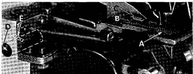
Length of stitch is determined by the combination of feed eccentricis used. Outer (left) eccentric (A, Fig. 14) actuates main (rear) feed dog; while the inner (right) eccentric (B) actuates the differential (front) feed dog.
In assembling feed eccentricities, be sure hubs are facing each other. Be careful not to damage shaft or key. Tighten nut (C) securely.
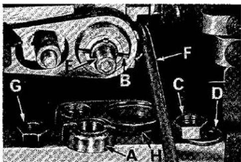
To change feed eccentrics, remove nut (C) and washer (D) from end of shaft (E). Turn handwheel in operating direction until key slot in eccentric is toward the front. Using hooked eccentric extractor (F), supplied with machine, reach behind eccentrics as shown and withdraw eccentrics. It may be necessary to move handwheel back and forth slightly during extraction.
text_image
Technical diagram of a mechanical assembly with labeled parts A, B, C, D, and EFig. 14
If eccentrics are unusually tight fitting, in addition to removing nut (C) and washer (D) (Fig. 15) from shaft (E), it may be helpful to remove nut (G) and feed driving connection (H). Then continue as originally suggested.
text_image
G F B C D A HFig. 15
SETTING THE PRESSER FOOT
Assemble the presser foot to presser arm. With needle in high position, swing presser arm into sewing position and set the presser foot to align needle holes (front and back) and flat on throat plate. The front edge of needle hole in presser foot must be aligned with front edge of needle hole in throat plate. It is also important that the bottom of the presser foot be flat on the throat plate. If necessary, presser foot can be realigned with throat plate slots by shifting the foot lifter lever shaft (H, Fig. 16). To move the shaft, loosen collar screws (B, Fig. 16) and clamp screw (G) and then shift the foot lifter lever shaft to the left or right as required. Retighten collar screws and clamp screw.
The foot lifter lever arm (A, Fig. 16) and the collar (B) secure the shaft. Be sure the presser arm does not bind and rise when presser foot release bushing is unlocked.
Adjust lifter lever stop screw (C) so that presser foot can be raised no higher than upper looper will permit; then tighten nut (D). There should be from 1/16 to 1/8 inch free motion of foot lifter lever before the presser foot begins to rise. This adjustment should be made with screw (E) and locked with nut (F). Re-assemble the chip guard, fabric guard and cloth plate. To assemble chip guard, turn handwheel until upper knife assembly reaches its highest position.

text_image
E F A G B C D HFig. 16
STARTING TO OPERATE (STYLE 39500 JK).
Be sure machine is threaded according to threading diagram (Fig. 1).
With thread tensions light, set upper and lower looper thread eyelets (N and R) about horizontal and in the middle of their front to back locations.
Operate machine slowly, without presser foot in place, to make sure that chain forms and moves off the tongue freely.
Swing presser foot into position, insert materials, and sew slowly.
NEEDLE THREAD CONTROL (STYLE 39500 JK)
While sewing on material, check needle thread control as follows: About 60% of needle thread required for the stitch should be drawn on needle downstroke.
To increase thread drawn on downstroke, position needle thread eyelet (AD, Fig. 1) farther to the rear. With needle at the bottom of its stroke, position needle thread eyelet (AD), so that needle thread cam-off (AE) just contacts the needle thread.
LOWER LOOPER THREAD CONTROL (STYLE 39500 JK)
Set lower looper thread eyelet (R, Fig. 1) about horizontal and all the way forward in its slot.
Frame looper thread guide (T) should be set with its eyelet approximately 1/8 inch to the right of lower looper heel eyelet, when lower looper is at the left end of its stroke.
UPPER LOOPER THREAD CONTROL (STYLE 39500 JK)
With material under presser foot, set upper looper thread eyelet (N, Fig. 1) to rest on top of lower looper thread eyelet, (R) and back far enough so upper looper thread is a little slack when upper looper reaches the left end of its stroke.
POSITIONING THE SQUARE EDGE (STYLE 39500 JK)
Position of lower looper thread at the edge is located by balancing needle and upper looper thread tensions.
To reduce amount of lower looper thread in the stitch, or close the edge more, increase lower looper thread tension.
STARTING TO OPERATE (STYLE 39500 JL)
Be sure machine is threaded according to threading diagram (Fig. 1A). With thread tensions light, set upper looper thread eyelet (N, Fig. 1A) about horizontal and back in its front to back location. Operate machine slowly, without presser foot in place, to make sure that chain forms and moves off the tongue freely. Swing presser foot into position, insert material, and sew slowly.
NEEDLE THREAD CONTROL (STYLE 39500 JL)
Usually, all needle thread is drawn on needle down stroke. At top of needle stroke, thread should be just tight enough to feed chain off stitch tongue. Needle threads tend to pull down slightly if excessive thread is pulled on the up stroke. With needles at bottom of stroke, position needle thread eyelet (AD, Fig. 1A) so that the needle thread pull-off (AE) draws the proper amount of needle thread to satisfy the above conditions.
UPPER LOOPER THREAD CONTROL (STYLE 39500 JL)
During needle downstroke, forward stroke of looper thread pull-off (AF, Fig. 1A) will draw upper looper thread through the tension. When normal amount of looper thread is drawn, upper looper thread will have almost all slack taken up as looper thread pull-off reaches its most rearward position.
If upper looper thread has loose appearance in the seam, move the upper looper thread eyelet (N, Fig. 1A) forward slightly. If, however, the eyelet is too far forward, the looper thread will tend to break excessively--even with a minimum amount of looper thread tension applied.
CAUTION! Do not try to obtain a tight looper thread appearance on the seam by carrying high tensions.
POSITIONING THE PURL TO OBTAIN A FLAT SEAM (STYLE 39500 JL)
If the purl is at the top edge of the garment, the seam can be opened into a near butted appearance. If, however, the purl is under the edge, a less flat and tighter seam results when opened.
Moving the needle thread eyelet (AD, Fig. 1A) back causes less thread to be pulled from the cones as the needles travel to the top of their stroke and causes the purl to form more on the top of the edge. If the eyelet is moved back too far, however, the threads become slack at the top of the stroke and the chain will not feed off the throat plate tongue. With a reasonable minimum needle thread tension to insure uniformity, the needle thread eyelet should be adjusted to position the purl as desired.
THREAD TENSIONS WITH RESPECT TO STITCH (STYLE 39500 JL)
The needle threads and looper thread tensions should be set at a minimum to insure uniformity of stitch. NOTE: Tension applied to the threads at the thread stand tension disc felt (L, Fig. 1A) should only be enough to prevent the threads from becoming slack between these tension pads and the tension discs mounted on machine. All controlling tension settings to insure uniformity of stitch should be obtained by varying the tensions at the tension discs, which are mounted on the machine.
TERMS
Prices are net cash and subject to change without notice. All shipments are forwarded f.o.b. shipping point. Parcel post shipments are insured unless otherwise directed. A charge is made to cover postage and insurance.

text_image
Technical diagram of a mechanical assembly with numbered parts and exploded views, including labeled parts like 'Zimex-Sawind' and numbered annotations.The parts illustrated on the preceding page and described below represent the parts that are used on Styles 39500 JK and JL, but not used on Style 39500 FA.
Those parts shown in phantom views and bearing no reference numbers are common to Styles 39500 FA, JK and JL.
Use Catalog No. 103 FA (Style 39500 FA) for all parts not illustrated or described in this catalog.
Reference numbers that are inside a bracket or box on the picture plate and have indented descriptions, indicate they are component parts of a complete part or assembly.


| Ref.No. | PartNo. | Description | Amt.Req. |
| 1 | 39592 AA | Right Needle Tension Nut, green, for Style 39500 JL | 1 |
| 39592 AA | Needle Tension Nut, green, for Style 39500 JK | 1 | |
| 39592 AB | Upper Looper Tension Nut, blue | 1 | |
| 39592 AC | Lower Looper Tension Nut, red, for Style 39500 JK | 1 | |
| 39592 Z | Left Needle Tension Nut, yellow, for Style 39500 JL | 1 | |
| 2 | 39592 AE-4 | Needle Thread Tension Spring, for Style 39500 JK | 1 |
| 39592 AE-8 | Looper Thread Tension Spring, for Style 39500 JK | 2 | |
| 39592 AE-1 | Looper Thread Tension Spring, for Style 39500 JL | 1 | |
| 39592 AE-1 | Right Needle Thread Tension Spring, for Style 39500 JL | 1 | |
| 39592 AE-2 | Left Needle Thread Tension Spring, for Style 39500 JL | 1 | |
| 3 | 39592 E | Felt Pad, for tension post mounting bracket | 1 |
| 4 | 294 | Screw, for attaching bracket and attaching bracket spacer | 2 |
| 5 | 8372 A | Washer, for attaching bracket and attaching bracket spacer | 2 |
| 6 | 39582 AN | Attaching Bracket, for thermal cutter | 1 |
| 7 | 39582 AM | "Attaching Bracket Spacer | 1 |
| 8 | 39563 N | Needle Thread Pull-off Eyelet, for Style 39500 JL | 1 |
| 9 | 39560 B | Lower Spreader, for Style 39500 JL | 1 |
| 10 | 39563 X | Top Cover Needle Thread Eyelet, for Style 39500 JL | 1 |
| 11 | 39578 TB | Chip Guard | 1 |
| 12 | 29477 KJ | Crankshaft and Needle Driving Arm Crank Assembly, for Style 39500 JL | 1 |
| 29477 JM | Crankshaft and Needle Driving Arm Crank Assembly, for Style 39500 JK | 1 | |
| 13 | 29477 JN | Needle Driving Arm Crank and Connecting Rod Assembly | 1 |
| 14 | 22596 G | Screw, for needle driving arm crank | 1 |
| 15 | 22587 M | Screw, for needle driving arm connecting rod | 2 |
| 16 | 39516-625 | Needle Bearing, .0625 inch diameter | 28 |
| 39516-626 | Needle Bearing, .0626 inch diameter | 28 | |
| 39516-627 | Needle Bearing, .0627 inch diameter | 28 | |
| 17 | 30-92 Blk. | Wood Plug | 1 |
| 18 | CO67 E | Cork Plug | 1 |
| 19 | 258 | Nut | 1 |
| 20 | 40-46 | Washer | 1 |
| 21 | 39541 A | Feed Drive Eccentric Key | 1 |
| 22 | 51-228 Blk. | Vent Plug | 1 |
| 23 | 39540 B-30 | Differential Feed Eccentric, for Style 39500 JK | 1 |
| 39540 B-70 | Differential Feed Eccentric, for Style 39500 JL | 1 | |
| 24 | 39540 B-30 | Main Feed Eccentric, for Style 39500 JK | 1 |
| 39540 B-100 | Main Feed Eccentric, for Style 39500 JL | 1 | |
| 25 | 39563 P | Needle Thread Pull-off, for Style 39500 JL | 1 |
| 26 | 39552 G | Needle Drive Arm, marked "D", for Style 39500 JL | 1 |
| 27 | 50-774 Blk. | Stop Pin, for needle | 1 |
| 28 | 22596 E | Screw, for needle driving arm | 1 |
| 29 | 154 GAS | Needle, for Style 39500 JK | 1 |
| 154 GCS | Needle, for Style 39500 JL | 2 | |
| 30 | 39556 J | Presser Arm, for Style 39500 JL | 1 |
| 31 | 39520 AV | Presser Foot, for Style 39500 JK | 1 |
| 39520 AW | Presser Foot, for Style 39500 JL | 1 | |
| 32 | 22768 B | Screw, for stitch tongue and hinge spring | 1 |
| 33 | 39530 G | Presser Foot Hinge Spring | 1 |
| 34 | 39597 AV | Presser Foot Stitch Tongue, marked "EW", for No. 39520 AV | 1 |
| 39597 AW | Presser Foot Stitch Tongue, marked "EX", for No. 39520 AW | 1 | |
| 35 | 39525 D | Needle Guard, front | 1 |
| 36 | 39525 E | Needle Guard, rear | 1 |
| 37 | 39524 BK | Throat Plate, marked "BV", for Style 39500 JK | 1 |
| 37A | 39524 BL | Throat Plate, marked "BW", for Style 39500 JL | 1 |
| 38 | 39550 V | Lower Knife Holder | 1 |
| 39 | 39550 K | Lower Knife Equalizer Spring Cover | 1 |
| 40 | 39550 J | Lower Knife Equalizer Spring | 1 |
| 41 | 22559 H | Screw, for lower knife equalizer spring | 1 |
| 42 | 39582 AP | Bottom Cover | 1 |
| 43 | 39582 AL | Bottom Cover Extension | 2 |
| 44 | 39580 AF | Throat Plate and Lower Knife Support Bracket | 1 |
| 45 | 39526 AB | Differential Feed Dog, vulcanized rubber feed surface | 1 |
| 46 | 39505 AB | Main Feed Dog, marked "AG", vulcanized rubber feed surface | 1 |
| 47 | 39568 Z | Frame Thread Guide, for Style 39500 JK | 1 |
| 48 | 73 X | Screw, for frame thread guide | 1 |
SALES OFFICES AND REPRESENTATIVES
tHandle Union Special and Columbia only.
\$Handle Lewis and Columbia only.
All others handle Union Special, Lewis and Columbia with certain exceptions.
UNITED STATES
ALABAMA, BIRMINGHAM, 732-84th Street, South, Lloyd D. Baldwin, Tel. 833-9904.
ALABAMA, MONTGOMERY 7, 1959 Amella Drive, Garnet H. Hamlet, Tel. 265-0942, P.O. Box 7203, Larry Crisler, Tel. 265-0942.
ARKANSAS, LITTLE ROCK, P.O. Box 1783, James T. Taylor, Tel. (501) FR 2-2356.
CALIFORNIA, LA PUENTE, 1527 Channelwood Drive, Bill Boylass, Tel. 330-3043.
★CALIFORNIA, LOS ANGELES 21, 1100 E. Pico Blvd., Paul M. Mason, Mgr., Tel. Madison 5-5828.
CALIFORNIA, SAN FRANCISCO 7, 1275 Mission St., Robert J. Yell, Tel. Undurhill 1-1580.
\$CALIFORNIA, SAN FRANCISCO 3, Apparel City Sewing Machine Co., 1155 Mission St., Tel. Market 1-6660.
COLORADO, ARVADA, Casey's Sewing Machine Service, 5719 Reed St., Tel. 424-6630.
CONNECTICUT, DANBURY, 22 Bemum Road, Robert W. Goines, Tel. 746-3652.
FLORIDA, MIAMI, 2519 N.W. 2nd Ave., Trimco Sewing Equipment, Inc., Tel. 633-1138.
FLORIDA, PLANT CITY, 506 N. Gordon St., James C. Morgan, Tel. 752-1829.
*GEORGIA, ATLANTA, 2120 Plasters Bridge Road, N.E., Merritt M. Ambrose, Mgr., Tel. 875-9237.
GEORGIA, COMMERCE, Lakeview Drive, J. Tom Hanley, Tel. 335-4061.
GEORGIA, DECATUR, 1713 Coventry Road, Joe V. Parker, Tel. 377-5559.
GEORGIA, DUBLIN, 1615 Knox St., John W. Jones, Tel. 272-4663.
GEORGIA, GAINESVILLE, RFD #1, John Bradberry, Tel. Cumming, Ga. 887-4732.
GEORGIA, WINDER, 805 Pinkney, B. D. Smith, Tel. 867-3208.
★ILLINOIS, CHICAGO 10, 400 N. Franklin St., Orville A. Ullrick, Mgr., Tel. 644-6920.
KANSAS, PRAIRIE VILLAGE, 7351 Rosewood, Cleo C. Smith. Tel. HE 2-1705.
KENTUCKY, LOUISVILLE 7, P.O. Box 7261, Raymond E. Hinton, Tel. 587-0042.
LOUISIANA, METAIRIE, 707 Trudeau Drive, Charles Wickersham, Tel. 729-4115.
MARYLAND, BALTIMORE 15, P.O. Box 2505, Ralph B. Foster, Tel. 727-8499.
\$MARYLAND, BALTIMORE 1, J. Dashew, Inc., 417 W Baltimore St., Tel. Lexington 9-1838.
†*MASSACHUSETTS, BOSTON 11, 179 Lincoln St., William E. Palm, Mgr., Tel. Liberty 2-0147.
†MASSACHUSETTS, CANTON, York St., RFD, Roy T. Peder- sen, Tel. 828-1412.
†MASSACHUSETTS, TAUNTON, P.O. Box #2 Raynham, Walter P. Godek, Tel. VanDyke 2-6149.
MICHIGAN, DETROIT, John Joyce, Tel. 584-4210.
MINNESOTA, MINNEAPOLIS, 2800 Texas Ave., St. Louis Park 26, Minn., Leonard W. Koshler, Tel. 644-6236.
MISSISSIPPI, JACKSON 3, 327 Eastview St., Jamie A. Boyette, Tel. Fleetwood 5-1976, 1717 Capitol Ave., Larry Lancaster, Tel. 354-3080.
MISSISSIPPI, TUPELO, 606 Racove Drive, BIII Haywood, Tel. VI 2-5848.
MISSOURI, KANSAS CITY 5, Textile Machinery Co., 915 Broadway, Tel. Victor 2-9558.
MISSOURI, ST. LOUIS 34, 9860 Guthrie Ave., Carl E. McLoughlin, Tel. Chestnut 1-2368, 3940 Shenandoah St., Jerry Hicks.
†NEW HAMPSHIRE, NASHUA, P.O. Box 257, Herman E. Haberman Jr., Tel. Tuxedo 2-9698.
NEW JERSEY, NORTH ARLINGTON, 32M Garden Terrace, Joseph Loglisci, Tel. 991-8211.
†NEW JERSEY, RUTHERFORD, 246 Sylvan St., Richard W. Whitson, Tel. Gancva 8-2178.
NEW JERSEY, WEST BERLIN, P.O. Box 26, Frank A. Neff, Tel. 767-4350.
NEW YORK, LATHAM, 57 Sylvan Ave., Clarence A. Wheeler, Tel. State 5-6371.
★NEW YORK, NEW YORK 1, 370 7th Ave., (Penn Terminal Bldg.), Clarence L. Rosenquist, Mgr., Tel. Chickering 4-8800.
NEW YORK, ROCHESTER, 14 Strathmore Circle, James Halbohm, Tel. LI 4-1882.
NEW YORK, ROCHESTER 9, A. J. Adams Co., 1051 Culver Rd., Tel. Butler 8-7250.
NEW YORK, UNIONDALE, 873 Henry St., Anthony Candell, Tel. Ivashoe 3-7477.
NORTH CAROLINA, GREENSBORO, P.O. Box 226, William D. Harrod, Tel. 299-9367. 4216 Pennydale Dr., Harold E. Miller, Tel. 292-0734.
OHIO, CLEVELAND, 4914 Pearl Road, Cut & Sew Equipment Co., Tel. 651-5901.
OHIO, COLUMBUS, P.O. Box 874, Larry Kolson. Tel. AXminister 1-1222.
OKLAHOMA, OKLAHOMA CITY 19, 2226 Southwest 53rd St., G. B. Wiley, Tel. 685-2836.
PENNSYLVANIA, ALLENTOWN, P.O. Box 542, Luther D Cassell, Tel. 797-2111.
PENNSYLVANIA, BETHLEHEM, 1212 Camoc St., Ed Deegan, Tel. 868-8204.
PENNSYLVANIA, BERWICK, 1013 E. 16th St., Donald McFadden, Tel. 752-2442.
PENNSYLVANIA, CLARKS SUMMIT, 428 West Grove Ave., John J. Laffer, Tel. JUniper 7-2820.
★PENNSYLVANIA, PHILADELPHIA 24, 4234 Mocalester Ave., Bon W. Merz, Mgr., Tel. Gladstone 5-9800.
†PENNSYLVANIA, NEW ALEXANDRIA, (Pittsburgh) P.O. Box 285, W. Dale Speer, Tel. (Pittsburgh) 563-3589.
PENNSYLVANIA, REAMSTOWN, P.O. Box 176, David M. Bender, Tel. 267-6109.
PENNSYLVANIA, YORK, P.O. Box 884, Harding 1. Powell, 854-8040, also A. C. Davis.
SOUTH CAROLINA, COLUMBIA, P.O. Box 4246, Virlyn R. Crisler, Tel. Sunset 7-0863, P.O. Box 4112; J. W. Carter, Tel. 254-4255.
SOUTH CAROLINA, GREENVILLE, 25 Sir Abbot St., Orville W. Gregory, Tel. Cedar 9-5539, Lewis Village, Apt 9-E, John Lawrence, Tel. 235-2213.
TENNESSEE, KNOXVILLE 19, 3905 Greenleaf Ave., Horace E. Clinard, Tel. 508-1865.
TENNESSEE, MEMPHIS 17, 4695 Dunn Rd., Richard J. Lindhorst, Tol. Mutual 5-6750.
TENNESSEE, NASHVILLE 12, 1602 South Observatory Drive, William J. Brouch, Tel. Cypress 2-5123. 2517 Woodberry Drive, F. M. Blunkall, Tel. 883-3352.
★TEXAS, DALLAS 19, 4200 Hines Blvd., P.O. Box 6727 J. H. Muir, Mar., Tel. Lakeside 6-8369.
TEXAS, CARROLLTON, 1404 Pannidello, John D. Troeger, Tel. CH 2-5309.
TEXAS, EL PASO, P.O. Box 9573, Edward E. Smith, Tel. 598-2928.
TEXAS, SAN ANTONIO, Jerry Gregory, P.O. Box 13126. Tel. DI 2-5924.
UTAH, SALT LAKE CITY, 1215 E. 13th South St., Larry F. Rosvall, Tel. IN 7-6931.
VIRGINIA, LYNCHBURG, P.O. Box 1075, Tom Taylor, Tel. 845-8901, also Gerald Morrison.
WASHINGTON, SEATTLE, 858 South 148th, Louis Spencer, Tel. MA 4-8083.
CANADA
Union Special Machine Co. of Canada, Ltd.
BRITISH COLUMBIA, N. BURNABY 2, James Murray, 1522 Madison Ave., Tel. MU 3-3917.
MANITOBA, WINNIPEG 2, Frank Thierman, Rm. 201, Whitla Bldg., 70 Arthur St., Tel. Whitehall 3-4933.
★ONTARIO, TORONTO 2B, Peter Fowler, Mgr.-Rep., 355 King St. West, Tel. Empire 6-2939.
★QUEBEC, MONTREAL 10, John Caschetto, Mgr.-Rep., 40 Mollere St., Tel. 276-2575.
FINEST QUALITY WORK
HIGHEST PRODUCTION RATES
LOWEST MAINTENANCE COSTS
Sales Agents For UNION SPECIAL Machines; Also Agent for (L) LEWIS and (C) COLUMBIA where marked.
AFRICA
(TEXTILE & BAG MAKING MACHINES) Berzack Bros., Ltd. REPUBLIC OF SOUTH AFRICA—JOHANNESBURG 135/7 Prlichard St. CAPETOWN—78 Darling St. DURBAN— 72/74: Commercial Road. PORT ELIZABETH—277 Main Street, RHODESIA, BULAWAYO—133 Fife St. SALISBURY —102 Sinien St. (L.)
(BAG CLOSING MACHINES) South African Scale Co. Phy., Ltd. REPUBLIC OF SOUTH AFRICA—JOHANNESBURG—32 Von Brandis St. BLOMFONTEIN—53 Zastron St. CAPETOWN—Wales and Bree Sts. DURBAN—22 Aliwal St. EAST LONDON—38 Argyle St., LADYSMITH, Natal—355 Murchison. PORT ELIZABETH—Box 611. Also at PIETERMARITZBURG, PRETORIA, VEREENGING and WORCESTER. RHODESIA, BULAWAYO—2 Leander House, Rhodes Street, SALISBURY—95 Victoria Street, ZAMBIA—KITWE-Blantyre Road.
ALGERIA, ALGIERS—Etab. Sayag, 8 Rue Altairac. ETHIOPIA, ASMARA—S.A. Calderoni Africa, Avenue P. Asfaha Woogen (L & C)
IVORY COAST-ABIDJAN—Ets. Joan Abila-Gal, Box 1798. (L & C)
KENYA, NAIROBI—Transcandla, Ltd., College House, Koinange St. (P.O. Box 5933) (L & C) (Also Uganda, Tanganyika and Zanzibar)
MALAGASY REPUBLIC—TANANARIVE—Soc. Ind. Et Com. De L'Emyme, Boite Postale 1075, 17 Rue Clemenceau (L & C)
MAURITIUS, PORT LOUIS—(Bag Closing & Bag Making Machines) Hall, Geneva, Langlois, Ltd., 42 Sir William Newton St.
MOROCCO, CASABLANCA—R. Goissmann & Fils, Rue El Idrissi Es Sckali (L)
NIGERIA, APAPA, LAGOS—Sunflag Knitting Mills (Nigeria) Ltd. 9 Warehouse Road. (L & C)
SUDAN, KHARTOUM—Franco Pinto [Sudan] Ltd., P.O. Box 305. [L & C]
HONG KONG—G. R. Coleman Co. (Hong Kong) Ltd., Rm. 305. Wing Tinn Building, 7-13 Wellington St.
INDIA, CALCUTTA—Parrot Sewing Machine (P.) Ltd. 9/1 Sovaram Byrack St. (L & C)
JAPAN, OSKA—Kondo Sewing Machine Co. 163, Umegoe-Cho Kita-ku. (L) Branch—Tokyo 6-3 Ginza, Chao-Ku. Also at Ashikawa, Fukai, Napaova, Niisata, and Okayama.
KOREA, SEOUL—Leborses-Handel A.G., Bm. 604, Bondo Blg. 180 1-ka Ulchiro Chung-Ku, Int. P.O. Box 1268. (L) LAOS, VIETIANE—Doris Freres, P.O. Box 133. (C & L) PAKISTAN, (WEST) KARACHI-2—Universal Trading Corp., 29 Zeenat Mansion, McIend Road. (EAST) (Bag closing and bag making machines) Thomas C. Keay, Ltd., 15 Baltic Street, Dundee, Scotland.
REPUBLIC OF CHINA, TAIWAN, TAIPEI—G. R. Coleman Co. (Taiwan) Ltd., 16 Non Yang St. (L & CI)
THAILAND, BANGKOK—Yip In Tsol & Co., Ltd., P.O. Box 23: (L & CI)
VIETNAM, SAIGON—S.A. Pour Le Riz et L'Indutri (Sarl) 147 Trinh Minn-The (B. P. 444) (C & L)
AUSTRALIA
SOLE DISTRIBUTORS: Capron, Carter Ply., Ltd., 86 Liverpool Street, SYDNEY. Branches at: BRISBANE—454 Brunswick St., Valley, N.1, MELBOURNE—154 A'Beckett St. AGENTS: SOUTH AUSTRALIA-ADELAIDE—William Charlick Ltd., London Road, Mile End, WESTERN AUSTRALIA PERTH—Thomsons Pty. Ltd., 789 Hay St. TASMANIA, LAUNCESTON-Sew Knit Pty. Ltd., 72-74 George St. (L & C)
EUROPE
AUSTRIA, YIENNA—Firma Noeschuster, Marichilferstr. 51, (L)
BELGIUM, BRUSSELS—Union Special Machine Corporation of America, 90 Rue de la Casemo, Gustave Thierle, Mgr. (C)
DENMARK, COPENHAGEN—Rothenborg Specialmaskiner for Sy-Industrien A/S, Nikolo1 Plads 23. Offices at: AAL-BORG, HERNING, KOLDING, ODENSE, RISSKOV-AARHUS AND SILKEBORG. (L & C)
FINLAND, HELSINKI-LAUTTASAARI:—Suomen Konellike O/Y, Vattuniemenkatu 13. Branches at TAMPERE-Pienteollisuo-stalo, TURKU, Humglistenkatu 7-B. (L & C)
FRANCE, PARIS—Cle. des Machines Union Special de France, 91 Ave. de la Republique—Thos., de Semlyen, Directeur. Branch at: ROUBAIX (NORD)—50 Ave. J. Tabas. LYON, VILLEURBANNE (RHONE) 58 rue Alexandre Boutin. TOULOUSE (HAUTE GARONNE) 12 BD. Montaignier.
GERMANY, STUTTGARY—Union Special Maschinenfabrik, G.m.b.H., Schwabstr. 33—A. W. Krisger, Managing Director. Th. M. Boanstra, Director of Sales, BRANCHES AT: BERLIN, BIELEFELD, EBINGEN, FRANKFURT, HAMBURG, KOLN, MUNCHEN, OCHTRUP.
GREAT BRITAIN—(Textile Machinery)—ENGLAND—OADSY [NR. LEICESTER]—Union Special Machine Company, Ltd., Mandervell Road, Industrial Estate, Mr. A. B. Fitzpatrick, Manager, LONDON—108 City Road (H. O. Hall, Manager). SALES OFFICES BRISTOL, L. J. Heard, 19 The Rides Kingswood, SCOTLAND, MILNGAVIE (GLASGOW)—Derrick R. Robinson, 48 Clochbar Avenue. SUB-AGENTS: LONDON, W. 1—G. Johnson & Son (Sewing Machinery), Ltd., 58 Great Titchfield Street. MANCHESTER 19—S. A. Smith, (Manchester) Ltd., Park Grove Works, Levanshulme, NORTHERN IRELAND—BEIFAST 15, Aktex Ltd. 186 Covehill Road. SCOTLAND, GLASGOW S.E.—Allardice & Co., 9 Stevenson Street. (C) (Bag Closing and Bag Making Machines) SCOTLAND, DUNDEE—Thomas C. Keay, Ltd., 15 Baltic Street—Agent for entire British Isles.
GREECE, ATHENS—Georges Yannekouras-Dimoulis, 30 Po-traki St. (L & C).
ICELAND, REYKJAUIK—Magnus Thorgeirsson, Skolavordustig To (L & C).
IRELAND, DUBLIN—(Textlife Machines) W. Blythman, 224 Parnell Street (L & C) (Bog Closing and Bag Making Machines) Thomas C. Keay, Ltd., 15 Baltic St., Dundee, Scotland.
ITALY, MILANO—Giovanni Conti & Nipoti, Via Varese 18. (L & C)
MALTA, VALLETTA—A. C. Wismayer & Co., Ltd., 62 Old Bakery Street, IL & CO
THE NETHERLANDS, AMSTERDAM—N. V. Machinehandel C. & H. Verbeek, Kloveniersburgwa! 77. Offices als ARNHEM, ENSCHEDE, GRONINGEN, ROTTERDAM, SITTARD, TILBURG. [L & C]
NORWAY, MANGLERUD—Jod. Jacobsen A/S, Enobakkvoien 117, BERGEN—Biomongst 24. (C)
PORTUGAL, OFORTO—Rost & Janus, Succs. Ldo., Rua Barao de Forrester 914. (L)
SPAIN, BARCELONA—Rapida, S.A., Via Layetano 37 (L) SWEDEN, BORAS—Rud. Nystrom & Co., A/B, Lilla Branneregaton 6. Branches at OREBRO-Slofsgaton 37-39, MALMO, S. Forstandsgaton 16. Sub-Agent STOCKHOLM, A/B Försberg & Kato, Tomtebogaton 38.
Union Special International, Inc.
ARGENTINA, BUENOS AIRES—FROMAC S.A.C., Division Pomaco Costura, S.A., San Jose 350. (Union Special Machine Company), (L & C)
BRAZIL, SAO PAULO—Pancostura S.A.—Industria e Comercia, Rua Aurora 59A-71. Branches at PORTO ALEGRE—Rua Voluntarios da Patria 533; RECIFE—Rua Princesa Isabel 105; RIO DE JANEIRO—Rua Alexandre MacKenzie 117. (C & L)
CHILE, SANTIAGO—Lowenstein & Stewart, S.A.C., Calle Santa Domingo 1740. (L & C)
COLOMBIA, BOGOTA—Mocalzado, Lido., Carrera 30 #12-99. Branches at BARRANQUILLA—Carrera 45-B #34-54. BUCARAMANGA—Calle 34 #17-45. CALI—Carrera 7 #13-33/35. MANIZALES—E. Breslauer, Carrera 22 #18.44. MEDELLIN—Carrera 51, 36-18, PERELRA—Cra. 8—#22-77. {L & C}
COSTA RICA, SAN JOSE—Enrique Rodrigues S., P.O. Box 1949. (L & C)
DOMINICAN REPUBLIC, SANTA DOMINGO—Roberto Dominques, G., Calle Dr. Pedro Urena 19. (L & C)
ECUADOR, GUAYAQUIE—Distribuidora Richard O. Custer, S.A., Malecon Simon Bolivar #2308. Branch at QUITO—Avenida Patria 768. (L & C)
EL SALVADOR, SAN SALVADOR—Vairo Hermanos, Colo- nia Vaire. (L)
GUATEMALA, GUATEMALA—Compania Agro Comerciel, S.A., An Axenida Sur Zóna 1. (L & C)
HONDURAS, SAN PEDRO SUIA—Jacobo E. Handel, P.O. Box 559 (L & C)
PUERTO RICO, SAN JUAN—Aberco Warehouse Corp., P.O. Box 2352. (L & C)
SURINAM, PARAMARIBO—Kirpalani's, Ltd., 17-27 Magden St. (L & C)
URUGUAY, MONTEVIDEO—Storer & Cla., S.A., Uruguaya, Mercedes 1312. (L)
VENEZUELA, CARACAS---H. Biahm, S.A., Dr. Paul A. Chorro 29.
NEAR EAST
CYPRUS, NICOSIA—Christodoulides Bros. & Co., 94 Tri-couppis St. (L)
IRAN, TEHERAN—Sava Trading Corp., Ave. Bozariomehri 081. Seroy Sadiyeh. (1 & C)
IRAQ, BAGHDAD—Sans of O. O. Agopian (IRAQ), F.O. Box 2021, Alwiyah. (L & C)
ISREAL, TEL AVIV—L. Taube, Ltd., 15 Lilleinblom St. (L) JORDAN—Bandar & Araclingl, B.P. 1144—Damas, Syria
LEBANON, BEIRUT—Sons of O. O. Agopian, P.O. 1165.
SYRIA, DAMAS—Bandar & Aractingi, B.P. 1144. (L & C) TURKEY, ISTANBUL—M. Benmayor, Mahmutpasa Abut Efendi Han Nr. 46-47. (L & C)
U.A.R., Cairo—Mistr Import & Export Co., 6 Rue Adly—Tech. Sub-Agent—A Kovaldian. S.A.R.L., 200 Shario Shubro (L & C)
NEW ZEALAND
SOLE DISTRIBUTOR: H. A. Tuck & Co., Ltd., 171 Albert St. AUCKLAND. BRANCH AT: WELLINGTON, Lees Bldg., Nelson St. (L) Also—New Caledonia, Cock Islands, Ellice Islands, Gilbert Islands, New Hebrides, Samoa (American), Tahiti, and Tonga. SUB-AGENTS: Glendermid, Ltd., CHRISTCHURCH, 20 O'Neill St. DUNEDIN, 193-196, Gotta St.
CHURCH—70 O'Brien St. DUNEDIN—1924-196 Caima St., P.O. Box 40. (C) FIJI SUVA—Kerl R. Fleischman, P.O. Box 502. (L) SAMOA (WESTERN), APIA—S. C. Percival, P.O. Box 204. (L)
PACIFIC ISLANDS
HAWAII, HONOLULU—(Textile Machines) Territorial Sales Co., 508 Atkinson Drive. (L). (Bag Closing and Bag Making Machines) H. S. Gray Co., 759 Puolca Rd.
PHILIPPINE ISLANDS, MAKATI, RIZAL—Atkins, Kroll & Co., Inc., 313 Malugay Street, (Buendia Extension). Branch at CEBU. (L & C)
WEST INDIES FEDERATION, JAMAICA
Union Special International, Inc.
JAMAICA, KINGSTON—Morris E. Parkin, 96 King St. (L) TRINIDAD, PORT OF SPAIN—Ackrill & Co., 17 Henry St. (L & C) Also—BARBADOS, GRENADA, TOBAGO.
Additional Sales Agents for (L) LEWIS and (C) COLUMBIA Machines
1-66

AUSTRIA IV, VIENNA—Franz Koerpert & Schne, K.G., Wiedner Hauptstrasse 36. (C)
BELGIUM, BRUSSELS—N. V. Machinohandel C & H Verbaek, Kruidluinalaan 570, Buryl Bldg. (L)
FRANCE, PARIS—Societe G. Armon & Cie., 14 Rue Commines (L)—Aspe-Dumont & Cie., 13 Rue de la Fontaine-Au-Roi. (C)
GERMANY, KREFELD—Herbert Jannsen, Alte Linnersitz. 104 (C. lie mach.)
GREAT BRITAIN—ENGLAND, LONDON, E.C.2—Eastman Machine Company, Ltd., 128-132 Curtain Road, CROYDON, 89 Beddington Lane, LEEDS—60 Merrton Street, MANCHESTER, 105-107A Corporation Street, SCOTLAND, GLASGOW 52—11 Drumsoch Place, Toryalen, NORTHERN IRELAND, BELFAST 14—W. F. Maxwell, 30 Glenbryn Park, REPUBLIC OF IRELAND, DUBLIN—Wm. Blythman, Ltd., 223/4 Pannell Street, (L)
ISRAEL, TEL AVIV—Israel Sewing Machine Co., 22 Yehudo Halevy St. (C)
MEXICO, MEXICO, D.F.—Casa Diaz de Maquinas de Casar, Av. Republic Del Salvador 89-93 (C)
MOROCCO, CASABLANCA—Durkopp Coudrex, 25 Rue Bascu-nanda. (C)
NORWAY, OSLO—J. A. Johnson A/S, Tarygaton 10. (L) REPUBLIC OF SOUTH AFRICA, JOHANNESBURG—African Sewing Machine Company (Pty.) Ltd., 118 President Street. Branches at: CAPE TOWN—110 Plain St., DURBAN—9 New Miester Lane (C)
RHODESIA, FEDERATION OF RHODESIA & NYASALAND, BULAWAYO—African Sewing Machine Company (Rhodesia) [Pvt.] Ltd., 2 Leonides House, 138 Rhodes Ave.
SPAIN, BARCELONA—Arbis S/A, Gerona 63. (C)
SWEDEN, BORAS—Hesqvarna, Industrisymaskiner A/B—Katrinedafsgatan 13. Branches: GOTEBORG—Sitigbergstiden 1 MALMO—Isak Sfaktaregatan 9—OREBRO—Stortogat 19—STOCKHOLM—Brunnsgatan 6-8. Agents—ULRICEHAM—Firma Hielmar Svensson, Tingshvsgatanz. (C)
SWEDEN, BORAS—A/B, A. C. Gustafson, Skolgaton 30, Branches: MALMO—Sevedsgaton 14, STOCKHOLM—Kungsgaton 18 Ulricham-Holdgaton 20. Sub-Agent—GOTEBORG—Symaskinsverkstaden special, Kongshojosgaton 7. (L)
SWITZERLAND, ZURICH—Fritz Zellweger & Sohne, Sel- naustr. 27, (L. except Button Sewer) Guttinger A.G., Sihlstrasse 37. (C)
URUGUAY, MONTEVIDEO—C. Brandes & Cle., S.A., Calle Rincan 658-60. [CI]

text_image
DEPENDABLE SERVICE WORLD'S FINEST QUALITY SINCE 1881UnionSpecial® INDUSTRIAL SEWING MACHINES
UNION SPECIAL maintains sales and service facilities throughout the world. These offices will aid you in the selection of the right sewing equipment for your particular operation. Union Special representatives and service men are factory trained and are able to serve your needs promptly and efficiently. Whatever your location, there is a Union Special Representative to serve you. Check with him today.
ATLANTA, GA.
MONTREAL, QUEBEC
BOSTON, MASS.
BRUSSELS, BELGIUM
CHICAGO, ILL.
LEICESTER, ENGLAND
DALLAS, TEXAS
LONDON, ENGLAND
LOS ANGELES, CAL.
PARIS, FRANCE
NEW YORK, N. Y.
STUTTGART, GERMANY
PHILADELPHIA, PA.
Representatives and distributors in all important industrial cities throughout the world.
UnionSpecial
MACHINE COMPANY
400 N. FRANKLIN ST., CHICAGO, ILL. 60610