35800BWDRG - Sewing machine Union Special - Free user manual and instructions
Find the device manual for free 35800BWDRG Union Special in PDF.

User questions about 35800BWDRG Union Special
0 question about this device. Answer the ones you know or ask your own.
Ask a new question about this device
Download the instructions for your Sewing machine in PDF format for free! Find your manual 35800BWDRG - Union Special and take your electronic device back in hand. On this page are published all the documents necessary for the use of your device. 35800BWDRG by Union Special.
USER MANUAL 35800BWDRG Union Special
text_image
35800 High Speed Feed - Off- The - Arm With Plain Feed Differential FeedMANUAL NO. PT0602-GR
STYLES
35800BLWG
35800BQWG
35800BWDNG
35800BWDRG
35800BWWG
35800BWWPG
First Edition Copyright 2006
By
Union Special Corporation Rights Reserved In All Countries
Printed in U.S.A. October 2006
PREFACE
This parts manual has been prepared to assist you in locating individual parts or assemblies on 35800 Series machines.
It is the desire of Union Special that each machine run at its optimum performance. Parts listed in this manual are designed specifically for your machine and are manufactured with utmost precision to assure long lasting service.
This manual has been comprised on the basis of available information. Changes in design and/or improvements may incorporate a slight modification of configuration in illustrations or part numbers.
On the following pages are illustrations and terminology used in describing the parts used on 35800 Series machines.
CONTENTS
SAFETY RULES 4
IDENTIFICATION OF MACHINES 5
CLASS DESCRIPTION 5
STYLE OF MACHINES 5
STYLE OF MACHINES (CONT.) 6
ILLUSTRATIONS 6
IDENTIFYING PARTS 6
TERMS 6
THREADING & OILING FOR PLAIN FEED 7
THREADING & OILING FOR DIFFERENTIAL FEED 8
NEEDLES 9
LUBRICATION 9
THREADING 9
ADJUSTING INSTRUCTIONS 9
TORQUE REQUIREMENTS 9
SYNCHRONIZING NEEDLE AND LOOPER MOTIONS 10
TIGHTENING NEEDLE HEAD 11
ALIGNING NEEDLES IN THROAT PLATE SLOTS 11
CENTERING THE CYLINDER....11
SETTING THE LOOPER 11
SETTING THE LOOPER AVOID PLAIN FEED 12
SETTING HEIGHT OF NEEDLE BAR 12
SETTING THE FEED DOGS FOR PLAIN FEED 12
SETTING THE FEED DOGS FOR DIFFERENTIAL FEED 12
SETTING THE FEED DOGS FOR DIFFERENTIAL FEED (CONT.) 13
CHANGING STITCH LENGTH 13
SETTING REAR NEEDLE GUARD 13
PRESSER FOOT AND PRESSER BAR ADJUSTMENT 14
UPPER FEED ROLLER ADJUSTMENT 14
UPPER FEED ROLLER ADJUSTMENT (CONT.) 15
THREAD TENSION AND RELEASE 15
DIFFERENTIAL CONTROL 15
SETTING NEEDLE THREAD TAKE-UP AND FRAME EYELET 16
LOOPER THREAD TAKE-UP ADJUSTMENT 16
FOLDER ADJUSTMENT 17
AIR BLOWER TUBE ADJUSTMENT 17
PULLER ADJUSTMENTS....17
PNEUMATIC ADJUSTMENTS 18
ADJUSTING STOP COLLAR ON FEED ROLLER FOR PNEUMATIC MACHINES 19
MAIN FRAME, CAST-OFF PLATE, EYELETS, MISCELLANEOUS COVERS AND BUSHINGS 21
MAIN FRAME, CAST-OFF PLATE, EYELETS, MISCELLANEOUS COVERS AND BUSHINGS (CONT.) 23
CYLINDER COVERS AND BUSHINGS FOR PLAIN FEED 25
CYLINDER COVERS AND BUSHINGS FOR PLAIN FEED (CONT.) 27
CYLINDER COVERS AND BUSHINGS FOR DIFFERENTIAL FEED 29
CYLINDER COVERS AND BUSHINGS FOR DIFFERENTIAL FEED (CONT.) 31
DETACHABLE HEAD ASSEMBLY 33
OILING, NEEDLE LEVER, CRANKSHAFT AND MAIN SHAFT PARTS FOR PLAIN FEED 35
OILING, NEEDLE LEVER, CRANKSHAFT AND MAIN SHAFT PARTS FOR DIFFERENTIAL FEED 37
PLAIN FEED BAR, FEED LIFT & FEED DRIVE COMPONENTS FOR PLAIN FEED 39
DIFFERENTIAL FEED BAR, MAIN FEED BAR, FEED LIFT ECCENTRIC ASSEMBLY FOR DIFFERENTIAL FEED 41
FEED DRIVE COMPONENTS, LOOPER DRIVE COMPONENTS AND LOOPERS FOR PLAIN FEED 43
LOOPERS, LOOPER HOLDERS, FEED DRIVE COMPONENTS AND LOOPER AVOID COMPONENTS FOR DIFFERENTIAL FEED 45
UPPER ROLLER FEED, FOOT LIFTER AND THREAD TENSION PARTS 47
UPPER ROLLER FEED, FOOT LIFTER AND THREAD TENSION PARTS (CONT.) 49
REAR ROLLER & PRESSER FOOT PNEUMATIC COMPONENTS & TREADLE SWITCH 51
PULLER DRIVE ASSEMBLY 53
SEWING PARTS FOR PLAIN FEED 57
SEWING PARTS FOR DIFFERENTIAL FEED 59
THREAD STAND 61
ACCESSORIES 62
NUMERICAL INDEX OF PARTS 63
NUMERICAL INDEX OF PARTS 64
NUMERICAL INDEX OF PARTS 65
NOTES 66
NOTES 67
SAFETY RULES
- Before putting the machines described in this manual into service, carefully read the instructions. The starting of each machine is only permitted after taking notice of the instructions and by qualified operators.
IMPORTANT! Before putting the machine into service, also read the safety rules and instructions from the motor supplier.
-
Observe the national safety rules valid for your country.
-
The sewing machines described in this instruction manual are prohibited from being put into service until it has been ascertained that the sewing units which these sewing machines will be built into, have conformed with the EC Council Directives (89/392/EEC, Annex II B).
Each machine is only allowed to be used as foreseen. The foreseen use of the particular machine is described in paragraph "STYLES OF MACHINES" of this instruction manual. Another use, going beyond the description, is not as foreseen.
-
All safety devices must be in position when the machine is ready for work or in operation. Operation of the machine without the appertaining safety devices is prohibited.
-
Wear safety glasses.
-
In case of machine conversions and changes all valid safety rules must be considered. Conversions and changes are made at your own risk.
-
The warning hints in the instructions are marked with one of these two symbols:

- When doing the following the machine has to be disconnected from the power supply by turning off the main switch or by pulling out the main plug:
8.1 When threading needle(s), looper, spreader etc.
8.2 When replacing any parts such as needle(s), presser foot, throat plate, looper, spreader, feed dog, needle guard, folder, fabric guide etc.
8.3 When leaving the workplace and when the workplace is unattended.
8.4 When doing maintenance work.
8.5 When using clutch motors without actuation lock, wait until the motor is stopped totally.
-
Maintenance, repair and conversion work (see item 8) must be done only by trained technicians or special skilled personnel under consideration of the instructions.
-
Any work on the electrical equipment must be done by an electrician or under direction and supervision of special skilled personnel.
-
Work on parts and equipment under electrical power is not permitted. Permissible exceptions are described in the applicable sections of standard sheet DIN VDE 0105.
-
Before doing maintenance and repair work on the pneumatic equipment, the machine has to be disconnected from the compressed air supply. In case of existing residual air pressure, after disconnecting from compressed air supply (i.e. pneumatic equipment with air tank), the pressure has to be removed by bleeding.
IDENTIFICATION OF MACHINES
Each UNION SPECIAL machine is identified by a style number, which is stamped into the style plate affixed to the middle of the machine under the tension assembly.
The serial number is stamped in the casting at the right rear base of the machine.
CLASS DESCRIPTION
High Speed, Feed-Off-The-Arm High Throw Machines, Two and Three Needle, Left Needle In Front. Light Weight Presser Bar Mechanism, Adjustable Looper Avoid, Space in Front of Needles 8" (203.2 mm), Single Disc Looper Thread Take-Up, Automatic Enclosed Type Oiling System and Filter Type Oil Pump, Visual Sight Oil Action and Supply Gauges, .588" [19/32", 15.1mm] wide roller.
STYLE OF MACHINES
35800BLWG9 DOUBLE LAP SEAM. Three needle, high capacity, differential feed with low lift feed eccentric and upper driven roller feed. -Typical Application- For in seams on medium weight denim garments. Seam Specification 401 LSc-3. Standard gauge Number 9 [9/64", 3.6mm]. Recommended needle 130GS, size 125/049. Maximum recommended speed 4500 R.P.M.. .040 step sewing parts.
35800BQWG9 DOUBLE LAP SEAM. Three needle high capacity, plain feed, upper driven, roller feed. - Typical Application- For in and out seams on medium weight denim garments. Seam Specification 401 LSc-3. Standard gauge Number 9[9/64", 3.6mm]. Recommended needle 130GS, size 125/049. Maximum recommended speed 4500 R.P.M.. .040 step sewing parts.
35800BWWG8, 9 DOUBLE LAP SEAM. Two and three needle, high capacity, differential feed, high lift feed eccentric, with upper driven, roller feed. Feed Dogs have higher teeth on front. - Typical Application-For in and out seaming on heavy weight denim garments. Seam Specifications 401 LSc-2 or 401 LSc-3. Standard gauge Numbers 8 [1/8", 3.2mm], 9 [9/64", 3.6mm]. Recommended needle 130GS, size 140/054. Maximum recommended speed 4500 R.P.M.. .094 step sewing parts.
NOTE: 18 gauge available with two needles only.
35800BWWPG8, 9 Same as 35800BWWG except presser and roller bars are equipped with double acting air cylinders. Air is used to supply down pressure and lift for presser foot and roller assembly.
35800BWDNG8, 9 Lower differential feed high step throat plate, wide presser foot with seam groove feed dogs flat front to back belt-driven, wide steel teeth feed roller.
35800BWDRG8, 9 Plain feed high step throat plate wide presser foot with seam groove raised front teeth on feed dogs belt-driven, wide steel teeth feed roller.
ILLUSTRATIONS
This manual has been arranged to simplify ordering repair parts. Exploded views of various sections of the mechanism are shown so that the parts may be seen in their actual position in the machine. On the page opposite the illustration will be found a listing of the parts with their part numbers, description and the number of pieces required in the particular view being shown.
Numbers in the first column are reference numbers only, and merely indicate the position of the part in the illustration. The reference number should never be used in ordering parts. Always use the part number listed in the second column.
Component parts of sub-assemblies which can be furnished for repairs are indicated by indenting their descriptions under the description of the main sub-assembly. As an example refer to the following text.
- 29126 EC Upper Looper Drive Shaft Assembly 1
- 22503 F Screw 1
- 39543 E Cam Follower Locking Clamp 1
It will be noted in the previous example that the cam follower, bushing and cam guide and the upper looper drive shaft are not listed. The reason is that replacement of these parts individually is not recommended, so the complete upper looper drive shaft assembly should be ordered.
When a part is common to all machines covered in this manual, no specific usage will be mentioned in the description. However, when the parts for the various machines are not the same, the specific usage will be mentioned in the description and, if necessary, the difference will be shown in the illustration.
A numerical index of all the parts shown in this manual is located at the back. This will facilitate locating the illustration and description when only a part number is known.
IDENTIFYING PARTS
Where the construction permits, each part is marked with its part number. On some of the smaller parts and on those where construction does not permit, an identification letter is marked in to distinguish the part from similar ones.
PLEASE NOTE: Part numbers represent the same part, regardless of which manual they appear. On all orders please include part number, name and style of machine for which the part was ordered.
TERMS
Prices are net cash and subject to change without notice. All shipments are forwarded F.O.B. shipping point. A charge is made to cover postage and insurance.
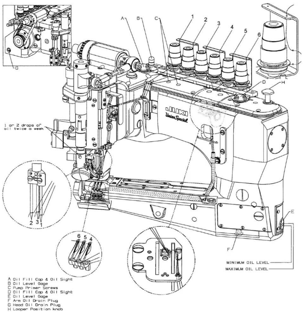
THREADING & OILING FOR PLAIN FEED
text_image
JUKI Union Specel 1 or 2 drops of oil twice a week A Oil Fill Cap & Oil Sight B Oil Level Gage C Pump Primer Screws D Oil Fill Cap & Oil Sight E Oil Level Gage F Arm Oil Drain Plug G Head Oil Drain Plug H Looper Position knob MINIMUM OIL LEVEL MAXIMUM OIL LEVELFIG. 1
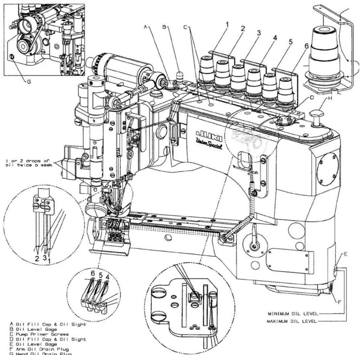
THREADING & OILING FOR DIFFERENTIAL FEED
text_image
JUKI Union Special 1 or 2 drops of oil twice a week A Oil Fill Cap & Oil Sight B Oil Level Gage C Pump Primer Screws D Oil Fill Cap & Oil Sight E Oil Level Gage F Arm Oil Drain Plug G Head Oil Drain Plug MINIMUM OIL LEVEL MAXIMUM OIL LEVELA Oil Fill Cap & Oil Sight
B Oil Level Gage
C Pump Primer Screws
D Oil Fill Cap & Oil Sight
E 011 Level Gage
F Arm Oil Drain Plug
G Head Oil Drain Plug
H Looper Position Knob
FIG. 1
| Needle Type | Description Sizes Available | |
| 130GS | Short double groove, struck groove, ball eye, spotted,government point, chromium plated. | 080/032, 090/036, 100/040, 110/044, 125/049,140/054, 150/060 |
Table I NEEDLES
Selection of proper needle size is determined by size of thread used. Thread should pass freely through the needle eye in order to produce a good stitch formation.
Each needle has both a type and size number. The type number denotes the kind of shank, point, length, groove, finish and other details. The size number, stamped on the needle shank, denotes largest diameter of blade, measured midway between shank and eye. Collectively, type and size number represent the complete symbol which is given on the label of all needles packaged and sold by UNION SPECIAL. See "STYLE OF MACHINES" for the standard recommended needle type & size for your machine.
To have needle orders promptly and accurately filled, an empty package, a sample needle, or the type and size number should be forwarded. Use the description on the label. A complete order would read: "1000 Needles, Type 130GS, Size 140/054".
LUBRICATION
The oil has been drained from the machine before shipping and the reservoirs must be filled before beginning to operate. Use a straight mineral oil with a Saybolt viscosity of 90 to 125 seconds at 100° Fahrenheit. Union Special Part No. 28604R.
Oil is filled at oil caps (A & D, Fig. 1). The level is checked at sight gauges (B) and (E). Maintain the oil level between the red lines of the gauges.
The machine is equipped with a continuous running rotary driven oil pump. The action of the oil can be observed through oil sight (A) and (D) in the front and back top covers.
When starting a new machine, filling the reservoirs or when beginning to operate a machine that has been idle for some time, it may be necessary to prime the pump. To do this, remove the two plug screws (C). Apply oil to these holes and operate machine until bubbling can be observed at the windows. Replace screws (C).
CAUTION: If oil does not bubble when machine is running, the circulating pump is inoperative.
Oil may be drained from the machine at two places, plug screw (F) located in the bottom of the cylinder and plug screw (G) at the back of the main frame below the handwheel.
THREADING
A convenient means for threading the looper has been provided. When loopers are at the left end of their travel, press the knob (H, Fig. 1) and loopers will back out of position, leaving them easily accessible. Thread the machine as illustrated in (Fig. 1). After threading, push loopers back into position.
ADJUSTING INSTRUCTIONS
NOTE: Instructions stating direction of location, such as right, left, front or rear of machine, are given relative to operator's position at the machine. The handwheel rotates counterclockwise, in operating direction; when viewed from the right end of machine.
TORQUE REQUIREMENTS
TORQUE REQUIREMENTS
TORQUE REQUIREMENTS
TORQUE REQUIREMENTS
TORQUE REQUIREMENTS
TORQUE REQUIREMENTS
TORQUE REQUIREMENTS
TORQUE REQUIREMENTS
TORQUE REQUIREMENTS
TORQUE REQUIREMENTS
TORQUE REQUIREMENTS
TORQUE REQUIREMENTS
TORQUE REQUIREMENTS
TORQUE REQUIREMENTS
TORQUE REQUIREMENTS
TORQUE REQUIREMENTS
TORQUE REQUIREMENTS
TORQUE REQUIREMENTS
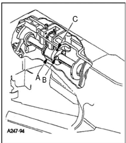
SYNCHRONIZING NEEDLE AND LOOPER MOTIONS

text_image
A243-94FIG. 2
NOTE: Needle and looper mechanisms are carefully synchronized with precision gauges before leaving the factory to insure the best possible sewing conditions.
Should it become necessary to disassemble the main shaft or replace components of the needle or looper drive mechanisms, re-synchronization of the machine will be required to facilitate proper sewing adjustments. This is accomplished by means of an adjustable split coupling located beneath the rear top cover, connecting the crankshaft to the main shaft, which in turn drives the looper mechanism.
To synchronize the machine, remove the needles, presser foot, throat plate, feed dogs and upper feed roller mechanism. Rotate handwheel in the operating direction until the needle bar is at the bottom of its stroke and just begins its upward travel. Loosen screw (A, Fig. 2) and remove the looper for the left hand needle from the looper holder. Insert a straight steel rod (B) 5/32" (3.9mm) or 11/64" (4.3mm) diameter by 2-1/2" (63.5mm) long into looper holder and retighten screw (A). It may be necessary to reposition the looper holder so that the rod (B) will be in a vertical position when at its farthest travel to the right. Rotate the handwheel until the rod is at extreme left, reinstall the throat plate. Turn the handwheel in the operating direction, with needle bar rising until rod (B) comes in contact with the edge of the throat plate. At this point, clamp Union Special timing gauge TT147 (C) around the needle bar (D), flush against the underside of the machine casting (E). Rotate handwheel in the opposite direction until either the gauge contacts the machine casting on the up stroke of the needle bar or the rod contacts the edge of the throat plate. Maximum allowable clearance between gauge and casting or rod and throat plate is .005" (0.1mm)
text_image
A247-94 A B CFIG. 3
If machine is not synchronized the following applies:
Both ends of the adjustable split coupling are secured to the crankshaft and main shaft by spot screws and set screws. On the main shaft end of the coupling (A, Fig. 3) three screws (B) thread horizontally through the coupling. The holes in the main shaft end of the coupling are larger than the diameter of the screws, permitting several degrees of rotation in either direction to properly synchronize the needle and looper. Loosen the three horizontal clamp screws (B, Fig. 3). With rod (B, Fig. 2) at its farthest position to the left, snug the uppermost horizontal clamp screw enough to hold coupling (A, Fig. 3) in position. If the handwheel is turned in reverse of operating direction and gauge (C, Fig. 2) on needle bar (D) contacts the machine casting (E) before rod (B) contacts the edge of the throat plate, loosen horizontal clamp screw (B, Fig. 3) which was snug, while holding the coupling in place with an Allen wrench in set screw (C). Rotate the handwheel slightly in reverse of operating direction, snug the uppermost horizontal clamp screw (B), recheck synchronization. If the handwheel is turned in reverse of operating direction and the rod contacts the edge of the throat plate before the clamp gauge contacts the machine casting, adjust as before, except turn the handwheel slightly in the operating direction. Use shim stock to insure no more than .005" (0.1mm) exists between gauge and casting or between rod and throat plate, in both the operating and reverse directions of the handwheel. When this setting has been made, tighten the three horizontal clamp screws (B, Fig. 3) securely, and recheck both clearance points with .005" (0.1mm) shim gauge to assure no slippage occurred while tightening the screws.
TIGHTENING NEEDLE HEAD
When replacement of the needle bar, and or needle head is necessary, torque the needle head to needle bar 14-16 in. lbs. (1.6-1.8Nm) or use torque rod No. 21227AR that has been supplied with the machine, for the purpose of eliminating the possibility of distorting the needle bar due to overtightening. Insert the torque rod in the hole at the upper end of the needle bar, while holding the needle bar head with a suitable tool, turn the needle bar with the torque rod onto the needle bar head. When the rod starts to bend, the needle bar head has been threaded into the needle bar properly.
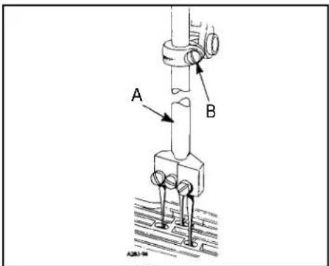
ALIGNING NEEDLES IN THROAT PLATE SLOTS
Insert a new set of needles, type and size specified, with screw (B, Fig. 4) slightly loosened, lower needle bar (A) and turn needle head as required until the needles are centered in the throat plate needle hole slots. Tighten screw (B) torque to 19-21in.lbs. (2.1-2.4Nm).
NOTE: If the needles cannot be aligned in the throat plate slots, the lower cylinder must be moved as stated below.
CENTERING THE CYLINDER
Remove the top front cover and gasket from the main frame. Loosen cylinder holding screw (A, Fig. 5). Turn eccentric screw (B) clockwise or counterclockwise to move the cylinder so the needles are centered in the needle holes. Tighten screw (A) and recheck settings.
NOTE: The cylinder may not move freely when the eccentric is turned because the joint sealant compound has set.
SETTING THE LOOPER
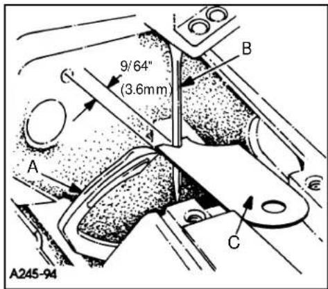
Insert a new set of needles, type and size specified. Always adjust the looper (A, Fig. 6) for the left needle first. Set the looper so that the distance from the center of the needle (B) to the point of the looper (A) is 9/64" (3.6mm) when the looper is at its farthest position to the left. Looper gauge (C) No. 21225-9/64 can be used advantageously in making this adjustment. If adjustment is required, loosen screw (A, Fig. 7) in looper holder, permitting movement in either direction to attain the 9/64" (3.6mm) dimension as shown in Fig. 6. Retighten screw (A, Fig. 7). Repeat for other needles and loopers.
Rotate handwheel in operating direction to assure that the looper point passes to the rear of the needle to touch but not to deflect the needle. This adjustment can be made by loosening screw (A, Fig. 7) in looper holder. Looper holder can be moved front to back to attain looper to needle setting. Always check the 9/64" (3.6mm) looper gauge setting after setting the looper to the back of the needle, and conversely, always check the setting of the looper to the back of the needle after setting the 9/64" (3.6mm) looper gauge.
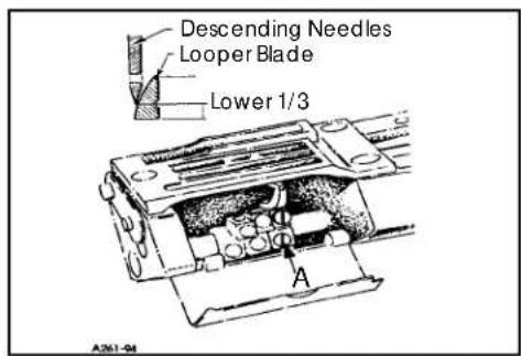
The amount of looper avoid has been set at the factory to .110" (2.8mm). If it becomes necessary to adjust the amount of avoid it is recommended as a starting point, to have the points of the descending needles contact the back of the lower 1/3 of the back of the looper blade. (See Fig. 7).
text_image
A BFIG. 4

text_image
Torque To 18 ft. lbs. A B A046-92FIG. 5
text_image
9/64" (3.6mm) A B C A245-94FIG. 6
text_image
Descending Needles Looper Blade Lower 1/3 A A261-04FIG. 7
text_image
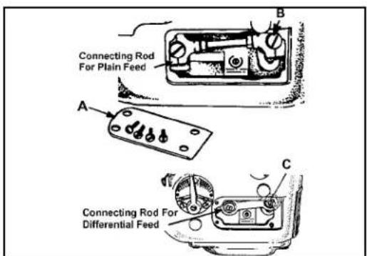
Connecting Rod For Plain Feed A B C Connecting Rod For Differential FeedFIG. 8
text_image
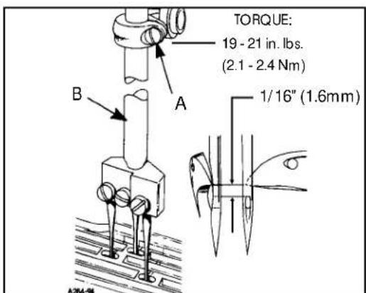
TORQUE: 19 - 21 in. lbs. (2.1 - 2.4 Nm) A B 1/16" (1.6mm)FIG. 9
text_image
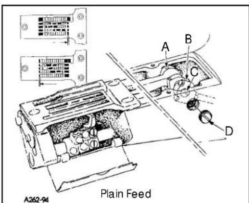
A362-94 Plain FeedFIG. 10

text_image
B C D E A Differential FeedFIG. 10A
SETTING THE LOOPER AVOID PLAIN FEED
If more or less looper avoid motion is required, remove cylinder side cover (A, fig 8) located at the lower front left side. For Plain feed use a screwdriver to loosen looper avoid link ball joint (B, fig 8) (for differential feed use TT-5 wrench to loosen looper avoid link screw C, fig 8). Moving ball joint down in the lever slot increases the amount of looper avoid motion, moving it up acts the reverse. Retighten ball joint B, Plain feed (screw C, differential feed) securely.
NOTE: Whenever looper avoid is changed looper clearance to needle must also be reset.
SETTING HEIGHT OF NEEDLE BAR
The height of the needle bar is correct when the top of the needle eye is 1/16" (1.6mm) below the underside of the looper, with the looper point even with the right side of the needle. To make adjustment loosen screw (A, Fig. 9) and move needle bar (B) as required to attain dimension.
NOTE: Care must be taken not to disturb the alignment of the needles when moving the needle bar either up or down.
SETTING THE FEED DOGS FOR PLAIN FEED
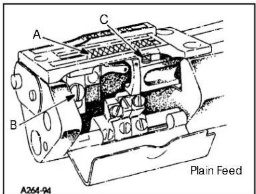
Assemble the main feed dog and throat plate. Main feed dog (A, Fig. 11) at its highest position, should be set to project above the throat plate, slightly more than the depth of its teeth for Style 35800BQWG. The feed dog mounting screw (B) and front support screw (C) should be set to maintain this setting.
The feed should be set so there is equal clearance between the front of the feed dog and the front of the feed slot in the throat plate when the feed dog is at its most forward travel. The same amount of clearance should be between the back of the feed dog and the back of the feed slot in the throat plate when the feed dog is at its most rearward travel. To attain this setting loosen screws (A and B, Fig. 10) and remove plug screw (D). Using a screw driver turn eccentric pin (C) clockwise or counterclockwise to obtain proper setting. Tighten screws (A and B), reinstall plug screw (D).
SETTING THE FEED DOGS FOR DIFFERENTIAL FEED
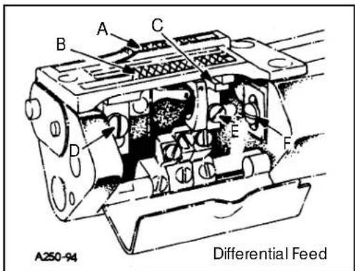
Before assembling the main and differential feed dogs, set the feed bar eccentric pin (A, Fig. 10A) located in the left side near center of cylinder, so that the slot in the head is in a horizontal position for the 35800BWDNG, BLWG style machines and turned counter clockwise to an approximate 45° for the 35800BWWG style of machine. The pin can be used to slightly tilt both feed dogs if necessary. The feed bar pin is retained in position by set screw (B). Assemble differential feed dog (A, Fig. 11A), main feed dog (B) and throat plate. Both the main and differential feed dogs can be individually adjusted to height. Main feed dog (B) at its highest position, should be set to project above the throat plate, the depth of its teeth. If adjustment is necessary loosen screw (D) and move feed dog (B) up or down to attain correct setting. Feed dog support (C) should support front of feed dog.
NOTE: If eccentric pin (A, Fig. 10A) is used to tilt the feed dogs, make sure that the looper does not interfere with the rear needle guard and that the needle guard does not pinch the needle loops on the back side of the needles.
SETTING THE FEED DOGS FOR DIFFERENTIAL FEED (CONT.)
If adjustment is necessary loosen screw (E, Fig. 11A) in feed dog support (C) and move as required. Retighten screw (E). The differential feed dog (A) may then be leveled with main feed dog (B). If adjustment is necessary loosen screw (F) and move feed dog up or down as required. Retighten screw (F).
NOTE: Should the main feed dog require repositioning due to contact with the throat plate in its forward or rearward travel, loosen set screw (C, Fig. 10A) in main feed bar driving link (D), rotate main feed bar eccentric driving stud (E) as required. Driving stud (E) has a thin hexagon head with cutouts on two of the flats allowing movement by tapping with a sharp pointed tool, when wrench 21388AZ is not available. Whenever the main feed bar eccentric driving stud position has been changed, recheck rear needle guard setting, adjustment may be required. Retighten set screw (C). Position main feed dog support (C, Fig. 11A) flush against bottom of main feed dog (B), tighten support screw (E) securely.
CHANGING STITCH LENGTH
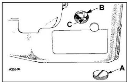
When change in stitch length is required, remove large plug screw (A, Fig. 12). Loosen feed rocker driving linkscrew (B) in lever (C). Moving the feed rocker driving link up in the lever slot lengthens the stitch, moving it down, shortens the stitch. Retighten link screw (B) securely and replace plug screw (A).
NOTE: If plug screw (A) is replaced with a new plug screw, it should be sealed with a silicone seal.
Any stitch length change, requires resetting the needle guard.
CAUTION: When making stitch length adjustment do not exceed maximum recommended stitch length due to possible part damage.
SETTING REAR NEEDLE GUARD
Set the rear needle guard (A, Fig. 13) horizontally so that it barely contacts needles (B) when at its extreme forward position. If adjustment is necessary loosen screw (E) and move guard front to back as required. It should be set vertically as low as possible, yet have its guarding surface in contact with the needles until the points of the loopers (C), moving to the right, are even with the right side of the needles. If adjustment is necessary loosen screw (F) and move guard and holder up or down as required.
CAUTION: If stitch length is changed, needle guard must be reset.
NOTE: When installing the needle it should be parallel with the eye in line of feed. If adjustment is necessary, loosen screw (N, Fig. 15) in needle head and rotate needle to attain adjustment (D, Fig. 13).
text_image
A B C A264-94 Plain FeedFIG. 11
text_image
A250-94 Differential FeedFIG. 11A
text_image
A263-94 B C AFIG. 12

text_image
D Left Side View Front View C E B F A 9 A260-94FIG. 13
PRESSER FOOT AND PRESSER BAR ADJUSTMENT

text_image
A BFIG. 14
text_image
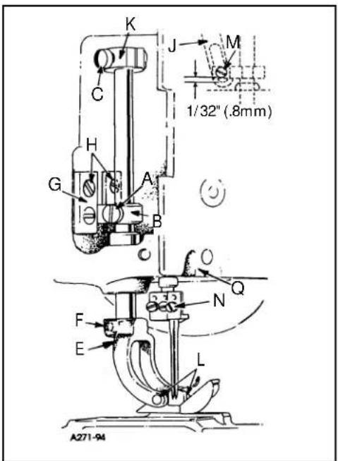
K J M C 1/32" (.8mm) H G A B C Q F N E L A271-94FIG. 15
Adjusting or Replacing Presser Foot:
Remove presser bar knob (A, Fig. 14) and spring (B). Loosen screw (A, Fig. 15) on presser barguide (B). (Loosen screws (C) in upper stop collar for pneumatic machines only). Slide presser bar upward high enough to slip on presser foot yoke (E) with foot attached and tighten screw (F) on flat of presser bar. Position foot so that the needle holes in the foot line up with the holes in the throat plate. Tighten screw (A)
Presser foot guide plates(G, Fig. 15) should be set so that entire presser foot and bar assembly has free movement up and down with no left to right movement.
With foot properly aligned on throat plate and presser barguide (B) securely fastened to presser bar, adjust both guide plates (G) to obtain above setting. Tighten four screws (H).
Reinstall presser barspring (B, Fig. 14) and knob (A), with presser foot resting on throat plate.
For pneumatic machines:
Set upper stop collar (K) to contact casting, so the bottom of the needle head and the top of the presser foot do not touch, at the bottom of the needle stroke when lifting foot. Tighten screw (C).
The presser foot should be adjusted to be 1/8" (3.17mm) above the throat plate before the feed roller mechanism begins to rise. Loosen screw (A, Fig. 15) in presser bar lifter and guide (B, Fig. 15), raise or lower guide as required to attain the specified point at which the feed roller begins to rise. Retighten screw (A) and maintain needle settings.
NOTE: There should be a minimum 1/32" (0.8mm) clearance between screw (M, Fig. 15) and the bottom of the slot in link (J).
Regulate the pressure on the presser foot by turning the presser spring regulating knob (A, Fig. 14) located on top of pressure foot spring (B)..
To remove just the presser foot, remove screws (L, Fig. 15) and replace foot, retighten screws (L).
text_image
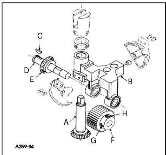
A259-94FIG. 16
Assembly of Roller to Roller Yoke:
Assemble driven gear (A, Fig.16) through feed roller frame (B). Place woodruff key (C) into slot of feed rollers shaft (D). Slide driven gear (E) on to shaft (D), make sure key (C) goes into slot in gear (E). While holding feed roller frame (B) with steel roller (F) between the two frame lobs, slide feed roller shaft (D) and assembled components through frame. Make sure that shoulder of roller (F) is to the right. Align screw (G) (first in operating direction on roller) on the flat of shaft (E). At the same time thrust shoulder of shaft (D) against face of gear (E), make sure left edge of roller is against right (inside) face of left lob. Secure screw (G) on flat of shaft (D) and tighten screw (H).
UPPER FEED ROLLER ADJUSTMENT (CONT.)
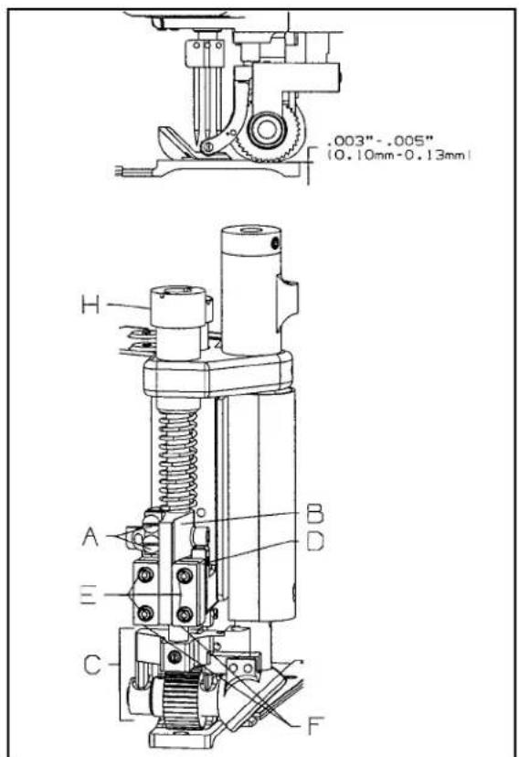
When feed roller mechanism (C, Fig. 17) has been removed or replaced, .003" (0.08mm) minimum to .005" (0.13mm) maximum clearance should be maintained between roller and throat plate.
To Adjust Guiding System for Roller:
Loosen two screws (A). Using shim(s) adjust feed roller mechanism (C) so that the roller is .003" (0.08mm) to .005" (0.13mm) above throat plate. Slide rear guide finger (B) down so that it sits on top of rear guide support block (D). Check to make sure roller is parallel to throat plate slots. Tighten two screws (A) to secure feed roller mechanism in place.
Setting Pressure for Feed Roller:
Regulate the pressure on the feed roller so that it exerts only enough pressure on the fabric to feed the work uniformly. Turning roller presser spring regulator (H, Fig. 17) clockwise to increase or counterclockwise to decrease the pressure.
Setting of Feed Roller:
Guide finger for roller should be set so that entire roller mechanism has free movement up and down with no left to right movement. With roller properly aligned, the edge of roller should be parallel with feed slots in throat plate.
Guide plates (F) must be thrusted against guide finger (B) to secure feed roller mechanism (C). Thrust guide plates (F) against guide finger (B) with equal pressure. Tighten four screws (E) to hold plates in place.
THREAD TENSION AND RELEASE
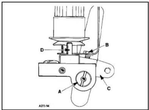
The thread tension release is set correctly when it begins to function at the point when the upper feed roller begins to rise. When adjustment is necessary, loosen screw (B, Fig. 18) in lifter lever (C). Facing the tension release shaft (A) from the right end of the machine, insert screwdriver in slot in shaft (A). Turn the screwdriver clockwise to raise pins (D) or counterclockwise to lower pins. Retighten screw (B).
DIFFERENTIAL CONTROL
The amount of differential is controlled by lever (A, Fig. 19). The adjusting plate is numbered from 1 to 9. When the lever is set from numbers 1 to 4 reverse differential or stretching occurs. The numbers from 4 to 5 produce equal feed stitching while numbers 5 to 9 produce a gathering stitch. Screws (B) can be set to limit the movement of lever (A) or lock lever in one position. If top ply of material is coming out long, move lever toward operator, if top ply is short, move lever away from operator, as required.
text_image
.003"-.005" [0.10mm-0.13mm] H A E C B D FFIG. 17
text_image
A273-94FIG. 18
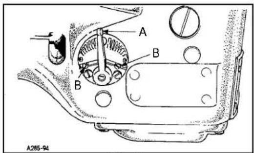
text_image
A B A285-94FIG. 19
SETTING NEEDLE THREAD TAKE-UP AND FRAME EYELET

text_image
A241-94 D H B A C K D C 1/16" (1.6mm)FIG. 20
With the needle bar at the top of its stroke set the adjustable frame needle thread eyelet (A, Fig. 20) in the lower mounting hole of eyelet (B) so the needle thread from eyelet (A) to the needle lever thread eyelet (C) will be in a straight line. If adjustment of eyelet (A) is necessary loosen screw (K) and move eyelet up or down as required. Retighten screw (K).
With the needle bar at the bottom of its stroke, the needle thread take-up (D) should be set so that it is 1/16" (1.6mm) above the edge of the needle lever thread eyelet (C) (See Inset). If adjustment is necessary loosen screw (H) and adjust lever (D) as required to attain 1/16". Tighten screw (H).
LOOPER THREAD TAKE-UP ADJUSTMENT
text_image
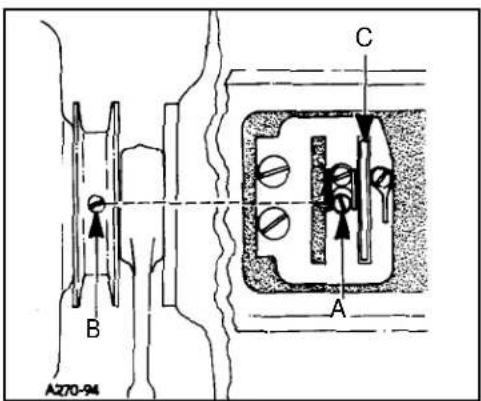
A270-94 B C AFIG. 21
With the machine rotating in operating direction the looper thread take-up is in time when the first screw coming into view (A, Fig. 21) is in line with the spot screw (B) on the main shaft in the pulley. NOTE: screw (A) is accessible through the hole in the take-up. With this setting correct, the looper thread should cast-off of the take-up (C) when the needles are safely in the triangle. If adjustment is necessary loosen two screws (A) in take-up (C) position screws in line with spot screw (B). Tighten screws (A).
NOTE: Make sure take-up cam is centered left to right in cast-off slot.
FOLDER ADJUSTMENT
Slide folder (A, Fig. 22) on arm. The folder should be as close to the front of presser foot (B) as possible, making sure to avoid the presser foot contacting the folder when sewing across seams. If adjustment is necessary loosen screws (C) to move entire folder left to right or front to back as required. If just adjustment of upper scroll (D) is needed loosen screw (E) and position scroll to obtain proper seam margin.
AIR BLOWER TUBE ADJUSTMENT
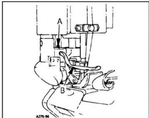
The air blower tube should be set left to right so it is parallel with the throat plate. It should be set front to back so when feeding over a cross seam the presser foot does not contact the tube. If adjustment is necessary, loosen screw (A, Fig. 23) and position air blower tube (B) as required. Retighten screw (A).
PULLER ADJUSTMENTS
Timing of the Puller Mechanism:
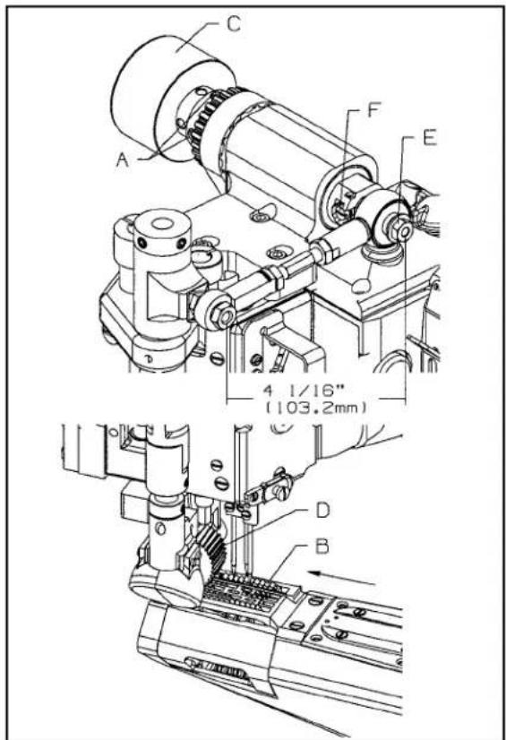
Loosen two screws (A, Fig. 24) in upper sprocket, rotate machine in operating direction, with needle moving up until needle points are flush with top of throat plate (B). At this point, feed dogs are above throat plate but have not made any movement towards the rear. Rotate puller shaft (C) in operating direction until puller (D) shows some movement clockwise. At this time tighten two screws (A) in upper sprocket.

text_image
1/32"-1/16" 0.8mm-1.6mmFIG. 22
text_image
A B A275-94FIG. 23
Setting Travel of Puller (stitch length):
Loosen nut (E, Fig. 24) and turn screw (F) clockwise to shorten puller travel or counterclockwise to lengthen puller travel. Tighten nut (E). Sewing sample should be checked to assure that proper stitch length is obtained.
text_image
C A F E 4 1/16" (103.2mm) D BFIG. 24
PNEUMATIC ADJUSTMENTS
Pneumatic settings can vary between different sewing applications. For best results set all air lines and air pressure settings as in (Fig. 25).
If air lines are disconnected follow connection as in (Fig. 25).
Air pressure settings should be set with air regulators as shown in (Fig. 26).
Air lines should be attached with each end of line to corresponding letter (Fig. 25).

text_image
29480AWD REGULATOR KIT FOR REAR PULLER SET TO ABOUT 50 P.S.I. C Y B X AIR SUPPLY "IN" (FRONT VIEW) FOR PRESSER FOOT SET TO ABOUT 30 P.S.I. (EBACK VIEW) SET TO ABOUT 60-70 P.S.I. Fig. 26Fig. 25
ADJUSTING STOP COLLAR ON FEED ROLLER FOR PNEUMATIC MACHINES
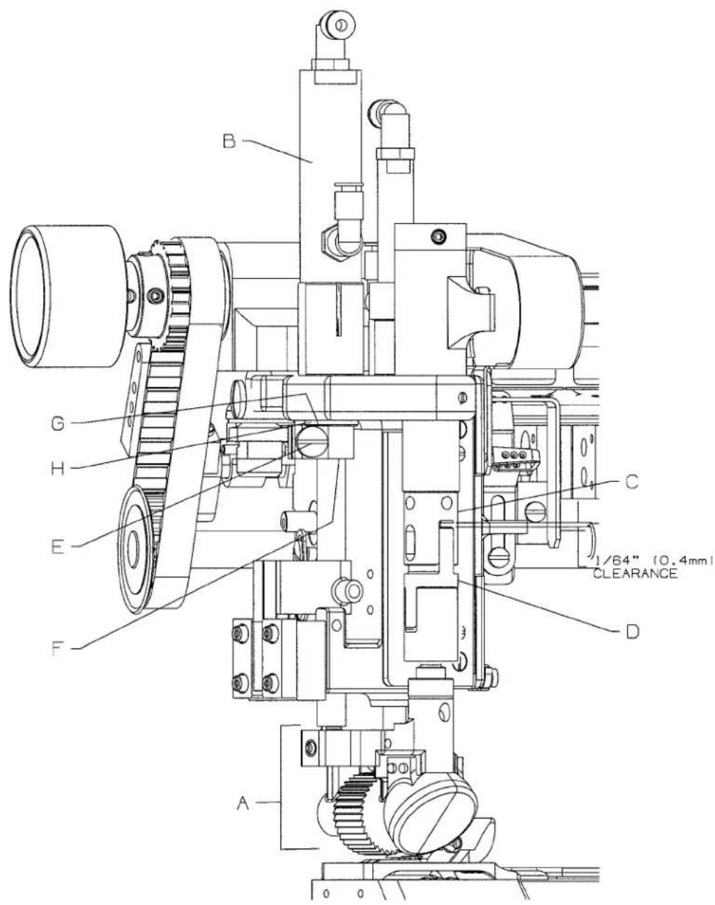
When feed roller mechanism (A, Fig. 27) and/or puller shaft cylinder assembly (B, Fig. 27) has been removed or replaced, 1/64" (0.4mm) clearance should be maintained between upper connection (C, Fig. 27) and floating feed roller connection (D, Fig. 27) when feed roller mechanism is in up position.
Turn off air supply to puller shaft air cylinder assembly (B, Fig. 27). Loosen screw (E, Fig. 27). Lift feed roller mechanism (A, Fig. 27) until there is 1/64" (0.4mm) clearance between upper connection (C, Fig. 27) and floating feed roller connection (D, Fig. 27). Slide roller stop collar (F, Fig. 27) and rubber washer (H, Fig. 27) up until they contact the underside of head assembly (G, Fig. 27). Retighten screw (E, Fig. 27).
text_image
B G H E F C 1/64" (0.4mm) CLEARANCE D AFig. 27

text_image
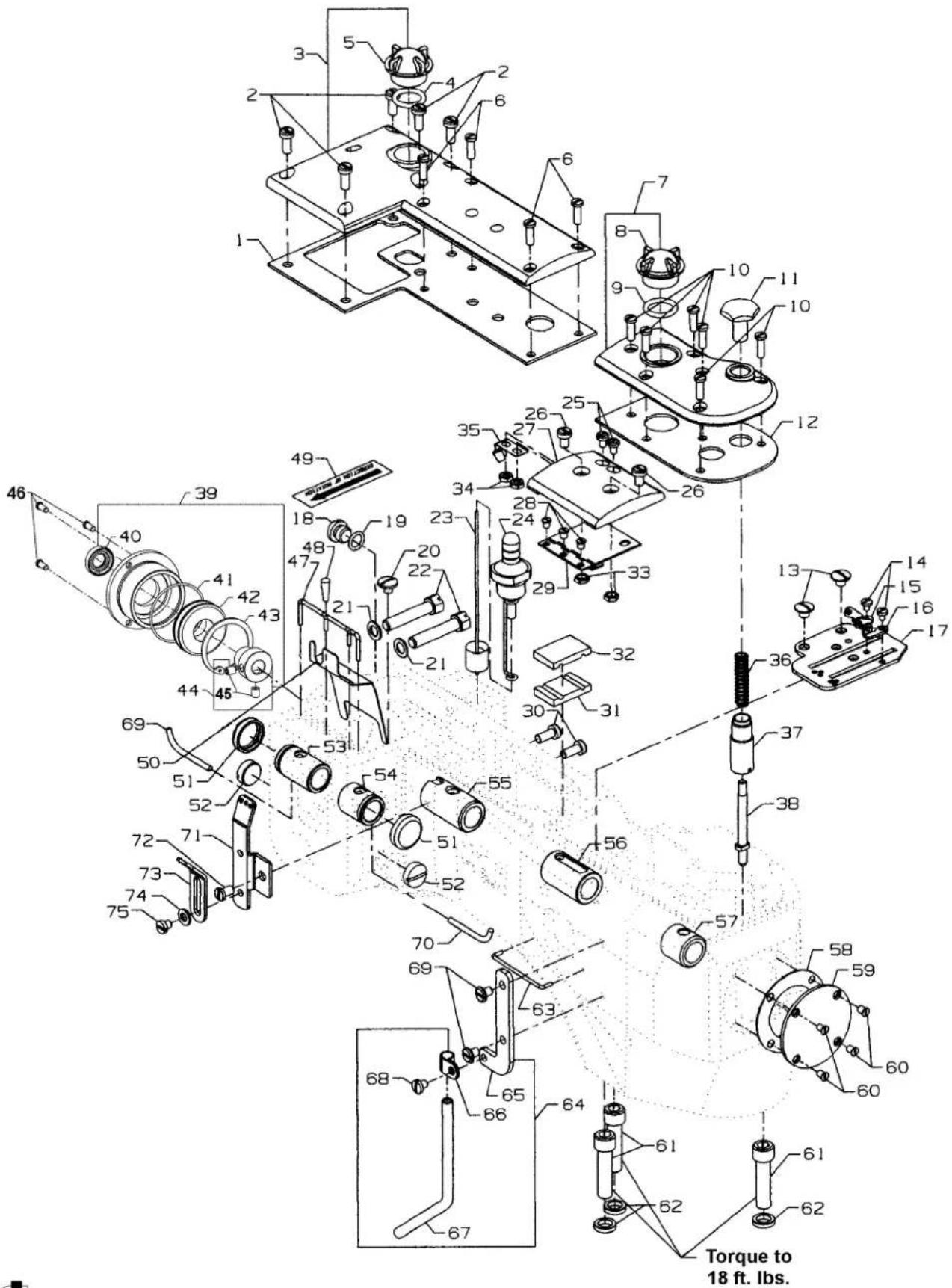
Exploded view diagram of a mechanical assembly with numbered components and labeled torque specificationsMAIN FRAME, CAST-OFF PLATE, EYELETS, MISCELLANEOUS COVERS AND BUSHINGS
| Ref. | Amt. | ||
| No. | Part No. | Description | Req. |
- 35888T Gasket 1
- 93 Screw 5
- 35888N Crank Chamber Cover.... 1
- 660-212 "O" Ring 1
- B3530555000 Oil Sight Gauge 1
- 22516A Screw 4
- 35887AE Top Cover, front 1
- B3530555000 Oil Sight Gauge 1
- 660-212 "O" Ring 1
- 22516A Screw 6
- 35853Z Looper Throw-Out Plunger Knob 1
- 35887AG Gasket 1
- 22730 Screw 2
- 73A Screw 2
- 35772S Cast-Off Plate Eyelet, rear 1
- 35772T Cast-Off Plate Eyelet, front 1
- 36204B Cast-Off Plate 1
- 22733B Oil Drain Screw 1
- 660-206 "O" Ring 1
- 22711 Screw, for oil wick.... 1
- 6042A Washer 2
- 22759A Screw 2
- 36293F Oil Sight Gauge Indicator Assembly 1
- 36293B Oil Sight Gauge 1
- 90 Screw 2
- 93A Screw 2
- 35887X Top Cover, middle 1
- 22564B Screw 3
- 35887R Middle Top Cover Hinge 1
- 93 Screw, for rotary pump housing 2
- 35893H Seal, Lower 1
- 35893G Seal, Upper 1
- 12934A Nut 2
- 41071G Nut 2
- 35887M Spring, top cover 1
- 35853Y Looper Throw-Out Plunger Spring 1
- 35853AA LooperThrow-Out Bushing 1
-
35853W Looper Throw-Out Plunger 1
-
thru 75. See following page.
text_image
Exploded view diagram of a mechanical assembly with numbered components and labeled torque specifications| Ref. | Amt. | ||
| No. | Part No. | Description | Req. |
- thru 38. See preceding page.
| 39. | 35890R | Bearing Housing Assembly | 1 |
| 40. | 660-764 | Lip Seal | 1 |
| 41. | 660-935 | "O"Ring | 1 |
| 42. | 50311C | Bearing | 1 |
| 43. | 661-348 | Retaining Ring | 1 |
| 44. | 36244D | Adaptor Bearing | 1 |
| 45. | 22894F | Screw | 2 |
| 46. | 22569B | Screw | 3 |
| 47. | CL21 | Oil Wick | 1 |
| 48. | C067E | Cork | 1 |
| 49. | LA527 | Directional Label | 1 |
| 50. | 35889H | Oil Shield | 1 |
| 51. | 35761D | Bushing Cap, plastic | 2 |
| 52. | 22539T | Plug Screw | 2 |
| 53. | 35860E | Needle Lever Shaft Bushing, rear | 1 |
| 54. | 35860D | Needle Lever Shaft Bushing, front | 1 |
| 55. | 35890E | Crankshaft Bushing, front | 1 |
| 56. | 35890Q | Mainshaft Bushing, rear | 1 |
| 57. | 36290B | Mainshaft Bushing, front | 1 |
| 58. | 35887AF | Gasket | 1 |
| 59. | 35887Z | Mainframe End Cover | 1 |
| 60. | 22766 | Screw | 4 |
| 61. | 22653E-24 | Screw | 3 |
| 62. | 35876U | Washer | 3 |
| 63. | 35781D | Looper Thread Guide Wire | 1 |
| 64. | 29105BH | Looper Thread Tube Assembly, for differential feed | 1 |
| - | 29105BL | Looper Thread Tube Assembly, for plain feed (not shown) | 1 |
| 65. | 35883AL | Support | 1 |
| 66. | 35866B | Clamp, tube | 1 |
| 67. | 35866A | Tube, for differential feed | 1 |
| - | 35866C | Tube, for plain feed (not shown) | 1 |
| 68. | SS7110510SP | Screw | 1 |
| 69. | 22829 | Screw | 2 |
| 70. | CL21 | Oil Wick | 1 |
| 71. | 35871B | Needle Thread Eyelet, three holes | 1 |
| 72. | 22570A | Screw | 1 |
| 73. | 35871A | Needle Thread Eyelet, three holes | 1 |
| 74. | 8372A | Washer | 1 |
| 75. | 22570 | Screw | 1 |

text_image
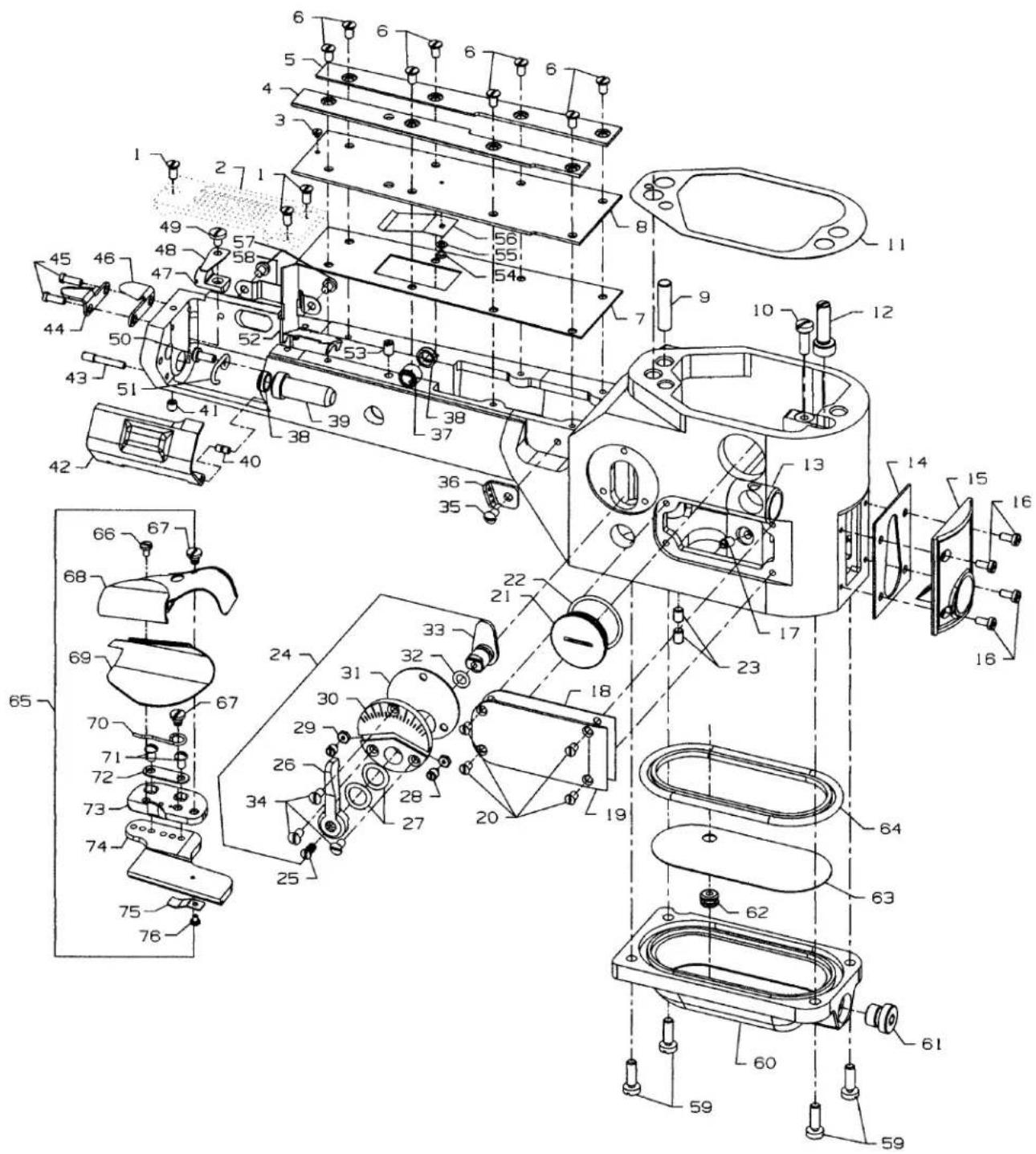
Technical diagram of a mechanical device with numbered components and exploded view, likely for assembly or maintenance purposes.CYLINDER COVERS AND BUSHINGS FOR PLAIN FEED
| Ref. No. | Part No. | Description | Amt. Req. |
| 1. | 35883G | Pin | 1 |
| 2. | 35883H | Cylinder Hinged Cover | 1 |
| 3. | 22791E | Screw Pin | 1 |
| 4. | 35883E | Spring | 1 |
| 5. | 90 | Screw | 1 |
| 6. | 35796C | Chain Cutter Blade, lower | 1 |
| 7. | 35796B | Chain Cutter Blade, upper | 1 |
| 8. | 22747 | Screw | 2 |
| 9. | ---- | Throat Plate (see to page 57) | 1 |
| 10. | 22524 | Screw, for all throat plates | 3 |
| 11. | 35883A | Cylinder Cover | 1 |
| 12. | 22798 | Screw | 3 |
| 13. | 27-435BLK | Washer | 2 |
| 14. | 35884E | Cylinder Lint Shield, upper | 1 |
| 15. | 35884F | Cylinder Lint Shield Spring | 1 |
| 16. | 35883J | Cylinder Cover Adjustable Gib | 2 |
| 17. | 22561A | Screw | 6 |
| 18. | 22526B | Screw | 8 |
| 19. | 36284 | Gasket | 1 |
| 20. | 35883M | Gasket | 1 |
| 21. | 667D-16 | Dowel Pin, straight | 1 |
| 22. | 36229A1 | Eccentric Pin | 1 |
| 23. | 531 | Screw | 2 |
| 24. | J87J | Screw | 4 |
| 25. | 35884H | Cylinder Cover and Oil Gauge | 1 |
| 26. | 35884R | Gasket | 1 |
| 27. | 35850C | Looper Shaft Bushing, front | 1 |
| 28. | 35850B | Looper Shaft Bushing, Middle | 1 |
| 29. | 51758 | Looper Thread Eyelet | 1 |
| 30. | 22849A | Screw | 1 |
- thru 60. See following page.
text_image
Technical diagram of a mechanical assembly with numbered components and exploded viewsCYLINDER COVERS AND BUSHINGS FOR PLAIN FEED (CONT.)
| Ref. | Amt. | ||
| No. | Part No. | Description | Req. |
- thru 30. See preceding page.
| 31. | 8372A | Washer | 1 |
| 32. | 22539H | Plug Screw | 1 |
| 33. | 660-1115 | "O"Ring | 1 |
| 34. | 22539AL | Plug Screw | 1 |
| 35. | 35897AX | Gasket | 1 |
| 36. | 22733A | Oil Drain Plug Screw | 1 |
| 37. | 35886B | Gasket | 1 |
| 38. | 35886C | Cylinder Side Cover | 1 |
| 39. | 22539C | Plug Screw | 1 |
| 40. | 22564B | Screw | 6 |
| 41. | 23420AY18-1/8 | Folder Assembly, for all Styles except formachines ending in "L" | 1 |
| 42. | 73A | Screw | 1 |
| 43. | 23424F | Folder Support Spring | 1 |
| 44. | 23424AA | Folder Support Slide | 1 |
| 45. | 23424T | Base | 1 |
| 46. | 23425T | Clamp, for sliding base | 1 |
| 47. | 22849A | Screw | 2 |
| 48. | 23424S | Spring | 1 |
| 49. | 22760A | Screw | 2 |
| 50. | 23422AY18-1/8 | Lower Scroll | 1 |
| 51. | 23421Y9-1/8 | Upper Scroll | 1 |
| 52. | 87U | Screw | 1 |
| 53. | 36256B | Looper Thread Guide Wire | 1 |
| 54. | 660-1117 | Oil Seal for 35850G | 1 |
| 55. | 35850G | Looper Shaft Bushing, rear | 1 |
| 56. | 22849 | Screw | 1 |
| 57. | 35884L | Lower Lint Shield | 1 |
| 58. | 22571A | Plug Screw | 1 |
| 59. | 531 | Screw, for feed lifter lever shaft | 2 |
| 60. | 88 | Screw, for feed rockershaft | 1 |

text_image
Technical diagram of a mechanical assembly with numbered components and exploded viewsCYLINDER COVERS AND BUSHINGS FOR DIFFERENTIAL FEED
| Ref. | Amt. | ||
| No. | Part No. | Description | Req. |
- 22524 Screw 3
- ---- Throat Plate (see page 59) .... 1
- 22798 Screw 1
- 35883N FolderGib,left....1
- 35883P Folder Gib, right 1
- 22564J Screw 8
- 35883AA Gasket 1
- 35883T Cylinder Cover 1
- 667D-16 Dowel Pin, straight 1
- 22596 Screw 1
- 36284 Gasket 1
- 36229A-1 Eccentric Stud, for Style 35800BWWG 1
- 36249A Looper Shaft Bushing, front 1
- 35884R Gasket 1
- 36284C Cylinder Cover and Oil Gauge, front 1
- J87J Screw 4
- 22560A Screw 1
- 36286B Gasket 1
- 36286 Cylinder Side Cover 1
- 22766 Screw 4
- 22539AL Plug Screw 1
- 660-1115 "O" Ring 1
- 531 Screw 2
- 29478CZ Differential Feed Control Assembly 1
- 538 Screw 1
- 36237K Operating Lever 1
- 36237J Spring Washer 2
- 36237H Stop Screw Pin 2
- 60078Z Nut 2
- 36238 Adjusting Plate 1
- 36238E Gasket 1
- 660-220 Oil Seal Ring 1
- 36237E Adjusting Lever 1
- 87A Screw 3
- 22849A Screw 1
- 35856Y LooperThreadEyelet 1
-
36237L Bushing, for feed bare eccentric stud 1
-
thru 76. See following page.
text_image
Technical diagram of a mechanical assembly with numbered components for identification and assembly reference.CYLINDER COVERS AND BUSHINGS FOR DIFFERENTIAL FEED (CONT.)
| Ref. | Amt. | ||
| No. | Part No. | Description | Req. |
- thru 37. See preceding page.
| 38. | 660-1117 | Oil Seal | 2 |
| 39. | 35850G | Looper Shaft Bushing, rear | 1 |
| 40. | 35883G | Pin | 1 |
| 41. | 22894W | Screw, for cylinder hinge coverspring support stud | 1 |
| 42. | 35883R | Cylinder Hinged Cover | 1 |
| 43. | 22791E | Screw Pin | 1 |
| 44. | 35796B | Chain Cutter Blade, upper | 1 |
| 45. | 22747 | Screw | 2 |
| 46. | 35796C | Chain Cutter Blade, lower | 1 |
| 47. | 36283C | Cylinder Hinged Cover Spring Support Stud | 1 |
| 48. | 35883U | Cylinder Cover Spring | 1 |
| 49. | 22585C | Screw | 1 |
| 50. | 22849 | Screw | 1 |
| 51. | 36256B | Cylinder Looper Thread Guide Wire | 1 |
| 52. | 36284Z | Lower Lint Shield | 1 |
| 53. | 531 | Screw | 1 |
| 54. | 22798 | Screw | 1 |
| 55. | 27-435BLK | Washer | 1 |
| 56. | 36284E | Upper Lint Shield | 1 |
| 57. | 22513D | Screw | 2 |
| 58. | 35896B | Cylinder Guard, for Looper | 1 |
| 59. | 22596 | Screw | 4 |
| 60. | 36282 | Bottom Cover | 1 |
| 61. | 999-196 | Screw | 1 |
| 62. | 661-150 | "O" Ring | 1 |
| 63. | 36293G | Screen | 1 |
| 64. | 36284F | Gasket | 1 |
| 65. | 23420AY18-1/8 | Folder Assembly, for all Styles except machines ending in "L" | 1 |
| 66. | 87U | Screw | 1 |
| 67. | 22760A | Screw | 2 |
| 68. | 23421Y9-1/8 | Upper Scroll and Base | 1 |
| 69. | 23422AY18-1/8 | Lower Scroll | 1 |
| 70. | 23424S | Lower Scroll Spring | 1 |
| 71. | 22849A | Screw | 2 |
| 72. | 23425T | Clamp Plate | 1 |
| 73. | 23424T | Base | 1 |
| 74. | 23424AA | Folder Support Slide | 1 |
| 75. | 23424F | Folder Support Spring | 1 |
| 76. | 73A | Screw | 1 |

text_image
TORQUE: 8 in. lbs. (0.90 Nm) TORQUE NEEDLE BAR TO NEEDLE HEAD 14-16 in. lbs. (1.6-1.8 Nm)DETACHABLE HEAD ASSEMBLY
Ref.
No. Part No.
Description
Amt.
Req.
- 35829AJ Detachable Head Assembly 1
- 35854B Bushing 1
- 35844N Bushing 1
- 35877AD Bearing Sleeve Assembly 1
- 35844T Bushing 1
- SS8120410SP Set Screw 1
- 35854A Bushing 1
- 35889G Plate, baffle 1
- 664F-16 Pin, taper.... 1
- 6042A Washer.... 1
- 318 Screw 1
- 35837P Guide Finger, rear 1
- SS6121010SP Screw 2
- 35838B Block, support, rear guide 1
- SS7121410TP Screw 2
- 35838A Plate, guide, roller bar 2
- SS4091015SP Screw 4
- 35884S Gasket 1
- 35882J Cover, head, left 1
- 29476YR Sewing Guard Assembly 1
- 35882T Puller Drive Cover Assembly 1
- 35896D Sewing Guard 1
- 666-340A Bumper Plug 1
- 9937 Nut 1
- WZ0641510KP Spring Washer 2
- 22758E Screw 1
- 22594 Screw 2
- 35877AM Roller Presser Bar 1
- 35822AE Presser Bar Air Shaft 1
- 35817S Needle Bar 1
- 35818CB-8 Needle Head for 8 gauge styles 1
- 35818CB-9 Needle Head for 9 gauge styles .... 1
- 605 Screw 3
- 35731A Plate, guide, presser bar 2
- 22513D Screw 4
- 35884T Gasket 1
- 35882K Cover, head, front 1
- 22768 Screw 2
- 35870 Take-Up, needle thread 1
- 57WB Nipper Plate, needle thread 1
- 15438C Spring 1
- 57WD Screw 1
- 22524 Screw 2
- 43296 Needle Thread Nipper Base 1
- 605 Screw 1
- 35843D Presser Bar Lift Clamp 1
- SS7111410TP Screw 1
- SD0640241SP Screw 1
- WO3 Yarn 1
- 35897CK Oil Wick Hook 1
text_image
Technical diagram of a mechanical assembly with numbered components and labeled parts in ChineseOILING, NEEDLE LEVER, CRANKSHAFT AND MAIN SHAFT PARTS
FOR PLAIN FEED
| Ref. | Amt. | ||
| No. | Part No. | Description | Req. |
- 35894V Oil Reservoir Cover, back 1
- 35897BU Oil Reservoir Outlet Tube 1
- 29472AA Oil Pump Assembly 1
- 22585A Screw 6
- 29472AC Oil Pump Assembly 1
- 35897CC Oil Pump Assembly Cover, rear 1
- 35897BV Intake Filter 1
- 35897BM Oil Pump Housing Cover, front 1
- 22571B Plug Screw 1
- 35897BV Intake Filter 1
- 21756G Vent Screw, for oil pump 2
- 35897BW Gasket 1
- 90 Screw 2
- 36261A Take-Up Shield 1
- 35894K Oil Reservoir, front 1
- WO3 Oil Wick 1
- 666-338 Oil Seal 1
- 35723C LooperThread Take-Up 1
- 22580D Screw 2
- 35895W Mainshaft and Crankshaft Coupling 1
- 22894K Spot Screw 2
- 22519F Screw 3
- 35895Z Washer Plate 1
- 22894J Set Screw 4
- 35897BY Oil Pump Driving Gear 1
- 22797 Screw 3
- 35895Y Collar.... 1
- 22894AM Screw 2
- 35763G Needle Bearing Retainer 4
- 35763F Needle Bearing 28
- 35822W Crankshaft 1
- 35862A Needle Lever Connecting Rod 1
- 22587B Screw 2
- 22894AM Screw 1
- 35847X Needle Lever Connecting Rod Pin 1
- 35815C Needle Lever 1
- 22596B Screw 2
- 77 Screw 1
- 35761 Needle Lever Shaft 1
- 51054A Link Pin 2
- 666-149 Oil Wick 2
- 56354D Needle Lever Link.... 1
- 35816 Needle Bar Connection 1
- SS7111120TP Screw 1
- 22564 Screw 1
- 35864F Needle Lever Thread Eyelet 1

text_image
Technical diagram of a mechanical assembly with numbered components and labeled parts in ChineseOILING, NEEDLE LEVER, CRANKSHAFT AND MAIN SHAFT PARTS
FOR DIFFERENTIAL FEED
| Ref. | Amt. | ||
| No. | Part No. | Description | Req. |
- 35894V Oil Reservoir Cover, back 1
- 35897BU Oil Reservoir Outlet Tube 1
- 29472AD Oil Pump Assembly 1
- 22585A Screw 6
- 29472AC Oil Pump Assembly 1
- 35897CC Oil Pump Assembly Cover, rear 1
- 35897BV Intake Filter 1
- 35897CH Oil Pump Housing Cover, front 1
- 22571B Plug Screw 1
- 21756G Vent Screw, for oil pump 2
- 35897BW Gasket 1
- 90 Screw 2
- 36261A Take-Up Shield 1
- 35894K Oil Reservoir, front 1
- WO3 Oil Wick 1
- 666-338 Oil Seal 1
- 35723C LooperThread Take-Up 1
- 22580D Screw 2
- 35895W Mainshaft and Crankshaft Coupling 1
- 22894K Spot Screw 2
- 22519F Screw 3
- 35895Z Washer Plate 1
- 22894J Set Screw 4
- 35897BY Oil Pump Driving Gear 1
- 22797 Screw 3
- 35895Y Collar 1
- 22894AM Screw 2
- 35763G Needle Bearing Retainer 4
- 35763F Needle Bearing 28
- 35822W Crankshaft 1
- 35862A Needle Lever Connecting Rod 1
- 22587B Screw 2
- 22894W Screw 1
- 35847X Needle Lever Connecting Rod Pin 1
- 35815C Needle Lever 1
- 22596B Screw 2
- 77 Screw 1
- 35761 Needle Lever Shaft 1
- 51054A Link Pin 2
- 666-149 Oil Wick 2
- 56354D Needle Lever Link.... 1
- 35816 Needle BarConnection.... 1
- SS7110910TP Screw 1
- 22564 Screw 1
- 35864F Needle Lever Thread Eyelet 1

text_image
Technical mechanical assembly diagram with numbered components and dimensional annotations in millimetersPLAIN FEED BAR, FEED LIFT & FEED DRIVE COMPONENTS
FOR PLAIN FEED
| Ref. | Amt. | ||
| No. | Part No. | Description | Req. |
- 22874C Screw 1
- ---- Feed Dog (see page 57) 1
- 35834U Feed Dog Holder 1
- 538 Screw, for adjusting feed dog height 1
- 35834V3 Feed Dog Holder Shim 2
- 376 Screw 1
- 35835B Needle Guard Holder 1
- 22768 Screw 1
- 35825AC Needle Guard 1
- 87U Screw, for needle guard 1
- 22580A Feed Dog Support Screw 1
- 35834R Feed Bar 1
- 35834N Bushing 1
- 35834G Bushing 1
- 666-47 Oil Wicking 1
- 660-548 Wire Spring Clip 1
- 35844Z Link Pin 2
- 35844Y Link.... 1
- SS8080310TP Screw 4
- 35844 Feed Lifter Lever 1
- 35844C Bushing 1
- 35736A Bushing 1
- 660-221 "O" Ring 4
- 35845D Feed Lift Lever Shaft 1
- 35843B Feed Rocker Shaft 1
- 35836 Feed Rocker 1
- 22747 Screw 1
- 22743 Screw 1
- 22572 Screw 2
- 35736A Feed Rocker Bushing 1
- 35736B Feed Rocker Bushing Key 1
- 29478BD Connecting Rod Assembly 1
- 22587E Screw 4
- 29101G Avoid Eccentric 1
Spot Screw 1
Screw 1 - 269 Nut, left thread 2
- 35847E Feed Lift Eccentric Connecting Rod 1
- 43246 Feed Rocker and Looper Avoid Eccentric Connecting Rod .... 1
- 18 Nut, right thread 2
- 35846 Ball Joint 1
Screw 2 - 35841B Ball Joint 1
- 22729C Screw 2
- 41355U Shim as required
- 35846B Washer 1
- 258 Nut 1

text_image
TORQUE TO: 28-30 in. lbs. (3.2-3.9Nm) TORQUE TO: 19-21 in. lbs. (2.1-2.4Nm) TORQUE TO: 19-21 in. lbs. (2.1-2.4Nm) TORQUE TO: 28-30 in. lbs. (3.2-3.9Nm) TORQUE TO: 19-21 in. lbs. (2.1-2.4Nm)P181-94
DIFFERENTIAL FEED BAR, MAIN FEED BAR, FEED LIFT ECCENTRIC ASSEMBLY FOR DIFFERENTIAL FEED
Ref.
No. Part No.
Description
Amt.
Req.
-
22528
-
-
87U
-
35825AC
-
22768
-
35835B
-
22528
-
-
22894P
-
35834W
-
22519
-
62238A
-
29478EB
- 29478DV
- 29103U
- 29103T
-
22587E
-
WO3
-
22894W
-
22894AA
-
269
-
36244
-
18
-
36244A
-
22729C
-
41255B
-
22747
-
22733G
-
36236L
-
77
-
35836A
-
36236K
-
36236J
-
22504C
-
36237
-
36236A
-
660-207
-
36237A
-
22845M
-
35836B
-
36234M
-
36234F
-
22587H
-
36234G
-
36236H
-
36236G
-
35834X
-
35834AB
-
22587H
-
36234G
-
35834AC
-
22804
-
36234C
-
660-220
Screw 1
Differential Feed Dog (see page 59) 1
Screw 1
Needle Guard 1
Screw 1
Needle Guard Holder 1
Screw 1
Main Feed Dog (see page 59) 1
Screw 1
Main Feed Bar Driving Link 1
Screw 1
Link Pin 1
Feed Lift Eccentric Assembly, for Styles 35800BWDNG8, BWWG8, BWWPG8 & 9 ...... 1
Feed Lift Eccentric Assembly, for Style 35800BLWG9, BWDNG9, BWWG9 1
Feed Lift Eccentric Assembly Ball Joint, for Assembly 29478EB....1
Feed Lift Eccentric Assembly Ball Joint, for Assembly 29478DV 1
Screw 2
Oil Wick 1
Set Screw 2
Spot Screw 1
Nut, left thread 1
Connecting Rod 1
Nut, right thread 1
Ball Joint, complete 1
Screw 2
Ball Fork 1
Screw 1
Screw 1
Bushing, for feed rocker shaft 1
Screw 2
Feed Rocker 1
Differential Feed Driving Link Slide Block 1
Differential Feed Bar Driving Link Stud 1
Screw 1
Differential Feed Adjusting Lever 1
Feed Rocker Shaft 1
Oil Seal Ring 1
Differential Feed Adjusting Lever Link 1
Screw 1
Differential Feed Bar Driving Link 1
Feed Bar Eccentric Stud 1
Differentail Feed Bar 1
Screw 2
Feed Bar Plate 1
Bushing 1
Differential Feed Bar Driving Link Stud 1
Main Feed Bar Ecentric Driving Stud 1
Main Feed Bar 1
Screw 2
Feed Bar Plate 1
Main Feed Dog Support 1
Screw 1
Feed Bar Slide Block 1
"O" Ring 1
text_image
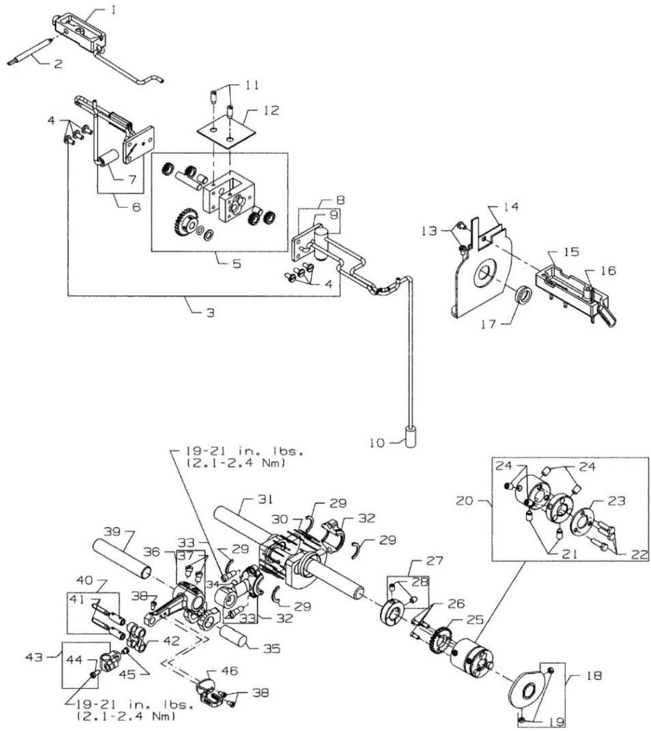
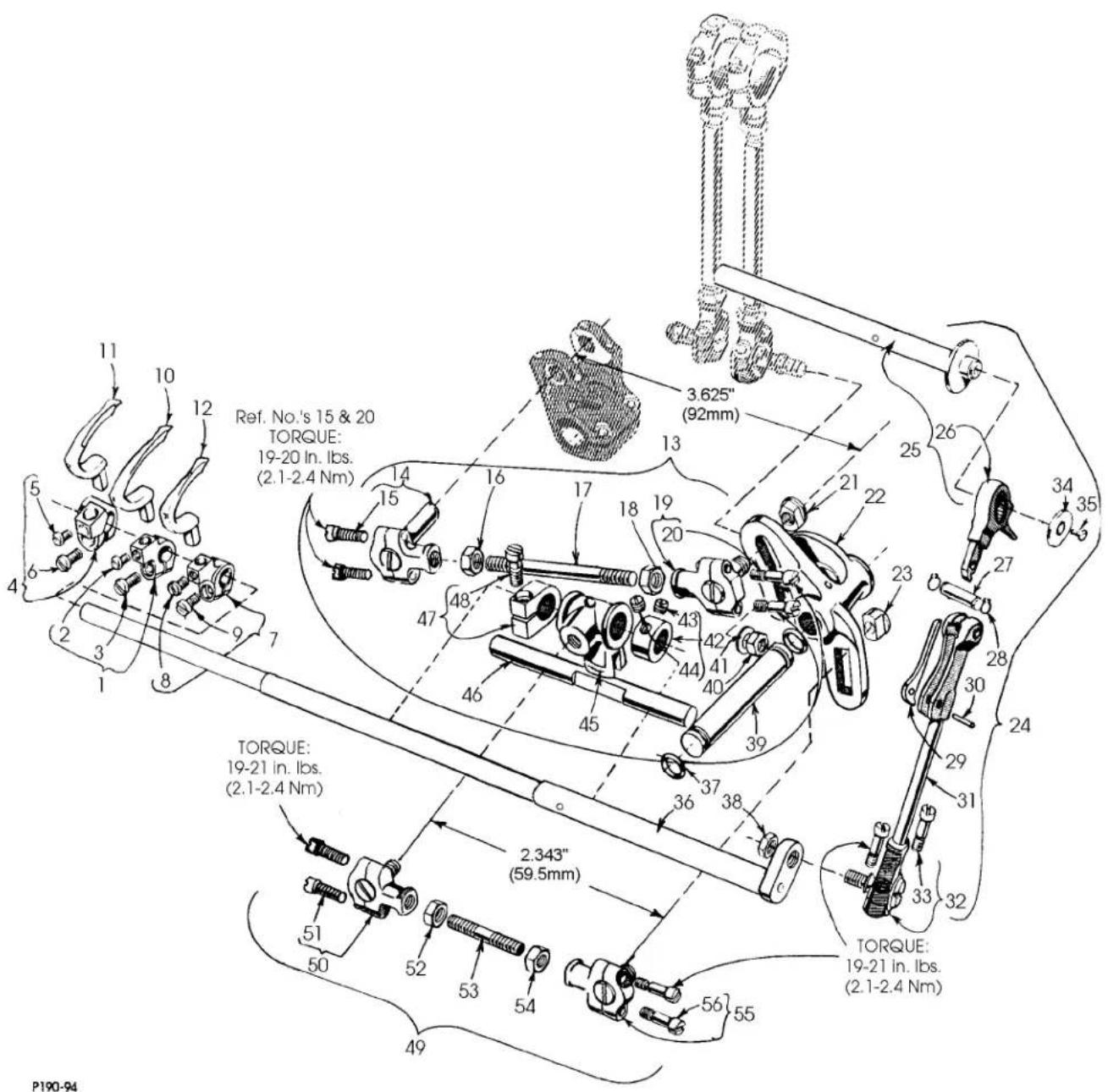
Ref. No.'s 15 & 20 TORQUE: 19-20 In. lbs. (2.1-2.4 Nm) TORQUE: 19-21 in. lbs. (2.1-2.4 Nm) 2,343" (59.5mm) TORQUE: 19-21 in. lbs. (2.1-2.4 Nm) P190-94FEED DRIVE COMPONENTS, LOOPER DRIVE COMPONENTS AND LOOPERS FOR PLAIN FEED
| Ref. | Amt. | ||
| No. | Part No. | Description | Req. |
-
35848E Looper Holder, marked "D", for middle looper.... 1
-
22564 Screw 1
-
22562A Screw 1
-
35848D LooperHolder, marked "C", for left looper.... 1
-
22564 Screw 1
-
22562A Screw 1
-
35848B Looper Holder, marked "A", for right looper 1
-
22564 Screw 1
-
22562A Screw 1
-
35809AY Looper, marked "AV", for right needle 1
-
35809BY Looper, marked "AY", for middle needle .... 1
-
35808AY Looper, marked "AU", for left needle 1
-
29478AH Feed Rocker Connecting Rod Assembly 1
-
35837A Ball Joint 1
-
22729C Screw 2
-
18 Nut, right thread .... 1
-
39141 Connecting Rod 1
-
269 Nut, left thread 1
-
35837N Ball Joint 1
-
22729C Screw 2
-
35866 Nut 1
-
35842 Feed Rocker and Looper Avoid Lever 1
-
35766A Nut 1
-
29478DZ Looper Drive Connecting Rod Assembly 1
-
35722AF Main Shaft Assembly 1
-
35853AJ LooperDriveConnection....1
-
35853V156 Hinge Pin 1
-
660-310 Tru-Arc Ring 2
-
56341G Locking Spring 1
-
50-458BLK Pin 1
-
35853AK Looper Drive Connecting Rod 1
-
35853AD Ball Joint, loopershaft 1
-
22729D Screw 2
-
35895V Washer 1
-
22526 Screw 1
-
35849B Looper Rocker Shaft 1
-
660-220 Oil Seal Ring 2
-
258A Nut 1
-
35842H Feed Rocker and Looper Lever Shaft 1
-
258A Nut 1
-
6042A Washer.... 1
-
35751F Looper Shaft Collar 1
-
88 Screw 1
-
89 Screw 1
-
35751 Looper Rocker Shaft Cross Head 1
-
35751B Cross Head Guide Shaft 1
-
35751G Thrust Collar 1
-
22752B Screw 1
-
29478AJ Connecting Rod Assembly 1
-
35851A Ball Joint 1
-
22729C Screw 2
-
18 Nut, right thread 1
-
35851G Connecting Rod 1
-
269 Nut, left thread 1
-
35851 Ball Joint 1
-
22729C Screw 2

text_image
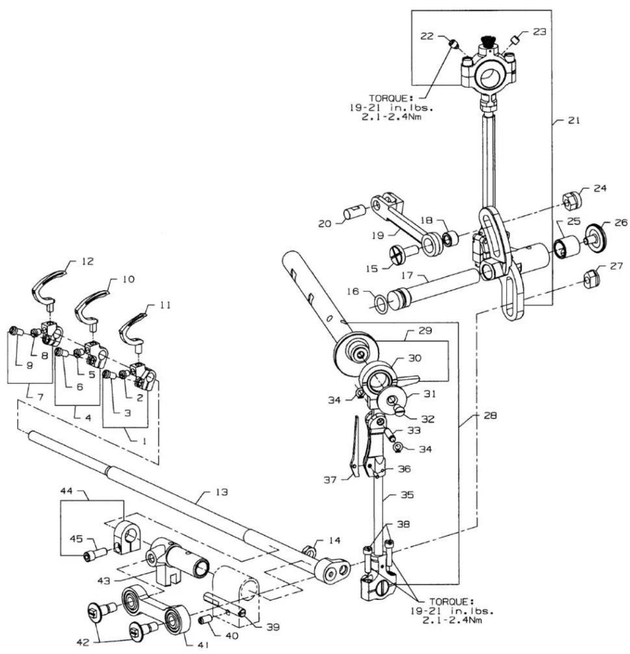
TORQUE: 19-21 in.1bs. 2.1-2.4Nm 22 23 21 20 18 19 15 17 24 25 26 27 29 30 34 31 32 33 34 36 35 37 38 28 13 14 13 44 45 43 42 41 40 39 TORQUE: 19-21 in.1bs. 2.1-2.4NmLOOPERS, LOOPER HOLDERS, FEED DRIVE COMPONENTS AND LOOPER AVOID COMPONENTS FOR DIFFERENTIAL FEED
Ref.
No. Part No.
Description
Amt.
Req.
- 35848B Looper Holder, marked "A", for right looper.... 1
- 22562A Screw 1
- 22564 Screw 1
- 35848E Looper Holder, marked "D", for middle looper.... 1
- 22562A Screw 1
- 22564 Screw 1
- 35848D LooperHolder, marked "C", for left looper.... 1
- 22562A Screw 1
- 22564 Screw 1
- 35809AY Looper, marked "AV", for right needle 1
- 35808AY Looper, marked "AU", for left needle 1
- 35809BY Looper, marked "AY", formiddle needle 1
- 35849C Looper Rocker Shaft 1
- 258A Nut 1
- 35836C Feed Rocker Driving Link Screw 1
- 660-207 Oil Seal Ring 1
- 36236A Feed Drive Shaft 1
- 36236H Bushing, for feed rocker driving link 1
- 36236C Feed Rocker Driving Link 1
- 62238A Link Pin 1
- 29478EC Feed Drive Assembly 1
- 22894W Screw 1
- 22894U Screw 1
- 35866 Nut 1
- 36236B Bushing 1
- 22733G Screw 1
- 35766B Nut 1
- 29478DZ Looper Drive Connecting Rod Assembly 1
- 35722AF Main Shaft Complete 1
- 35853AJ Looper Drive Connection 1
- 35895V Shaft Stop Washer 1
- 22526 Screw 1
- 35853V156 Hinge Pin 1
- 660-310 Truarc Ring 2
- 35853AK Looper Drive Connecting Rod 1
- 50-458BLK Pin 1
- 56341G Locking Spring 1
- 22729C Screw 2
- 36278C Stud, for loopershaft sleeve 1
- 22560A Screw 1
- 35851S Connecting Rod Bearing Shell 1
- 35851P Screw 2
- 36249B Looper Shaft Sleeve 1
- 35751G Looper Shaft Collar 1
- 22572B Screw 1
*For older style machines these parts
must be purchased as assembly 29478FH

text_image
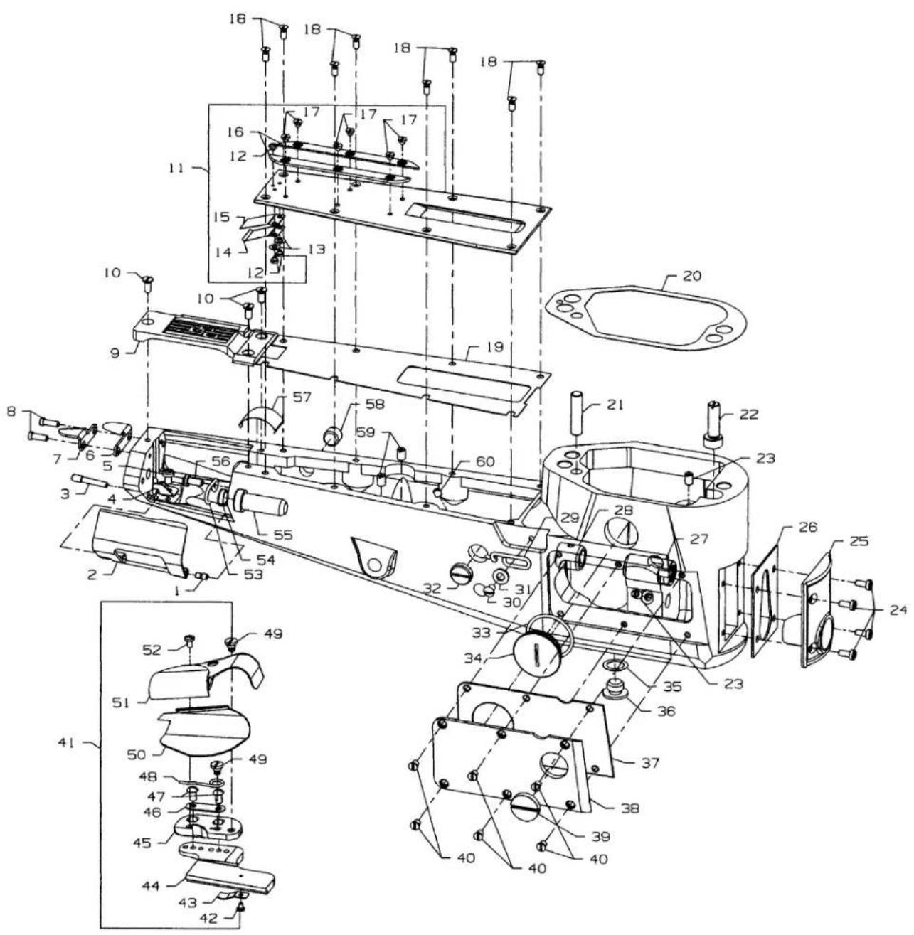
Technical diagram of mechanical assembly with numbered components and sectional views, including side views like 'AS VIEWED FROM THE RIGHT SIDE'.UPPER ROLLER FEED, FOOT LIFTER AND THREAD TENSION PARTS
| Ref. | Amt. | ||
| No. | Part No. | Description | Req. |
- 36280V Lifter Lever Link Assembly 1
- 36280U Lifter Lever Link.... 1
- 22585C Screw 2
- 86 Screw 2
- 35892A Puller Bar Knob, rear 1
- 50377L Spring, puller bar 1
- 22758C Screw 2
- 35835F Lifter Lever Bell Crank Link 1
- 35877AM Roller Presser Bar 1
- 29478ED PullerAssembly.... 1
- 54274C Feed Roller Lower Connection .... 1
- 22894P Screw 2
- 14649 Drive Gear Collar 1
- 88 Screw 2
- 22894C Screw 1
- 22738 Screw 4
- 35875Z Gear guard, rear 1
- 35877AA Woodruff Key 1
- 35873AK Feed Roller Shaft 1
- 35875X Driven Miter Gear 1
- 35875Y Drive Miter Gear 1
- 35873AJ Feed Roller Frame 1
- 660-303 Needle Bearing 2
- 35875AA Gear Guard, front 1
- 21237ES Air Blower Tube 1
- 73C Screw 1
- 35826X Feed Roller 1
- 22894W Screw 2
- 35826DZ Wide Rubber 1
*30. 22894W Screw 2 - 35826CB Feed Roller, Same as 35826X but reverse teeth 1
-
22894W Screw 2
-
thru 69. See following page.
*Items can be purchased as an extra send charge.

text_image
Technical diagram of mechanical assembly with numbered components and views, including exploded and assembled views.UPPER ROLLER FEED, FOOT LIFTER AND THREAD TENSION PARTS (CONT.)
Ref.
No. Part No.
Description
Amt.
Req.
-
thru 32. See preceding page.
-
35822AE Presser Bar.... 1
- 35843D Presser Bar Lifter and Guide 1
- SD0640241SP Screw 1
- SS7111410TP Screw 1
- 35880L Lifter Lever Connecting Link 1
- 22758C Screw 1
- 35880N Presser Bar Lifter Lever 1
- 35880P Lifter Lever Bell Crank 1
- 22894J Screw 1
- 35832A Spring, presser bar.... 1
- 35843C Presser Bar Knob 1
- 36292N Tension Release Shaft 1
- 660-219S Pin 1
- 22784F Screw 1
- 36292M Tension Plate Bracket 2
- 22517 Screw 2
- 35792T Tension Disc Release Pin 7
- 36292K Tension Release Shaft Spring 1
- 36280W Lifter Lever 1
- 22839D Screw 1
- 94 Screw 2
- 36298H Tension Support 1
- 22585A Screw 6
- 36298G Tension Thread Eyelet 3
- 36292Q Tension Post 6
- 109 Tension Disc, small 6
- 35792 Tension Disc, large 6
- W56392F Shield, tension spring 6
- 51292F4 Looper Thread Tension Spring, for looper 3
- 51292F14 Needle Thread Tension Spring, for needle 3
- 39592AK Tension Post Ferrule 6
- WC50092S Tension Nut 6
- 255 Screw 1
- 36280T Lifter Lever Connecting Link 1
- 36280S Presser Foot Connection Lifter Lever 1
- 22517 Screw, for presser foot lifter bearing bracket 1
- 36280N Presser Foot Lifter Bearing Bracket 1
- 660-254C Retainer Ring 2
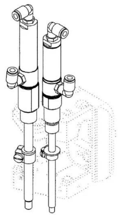
natural_image
Technical line drawing of two vertical cylindrical mechanical components with flanged ends and mounting brackets (no text or symbols)
text_image
Technical diagram of a mechanical assembly with numbered components and labeled parts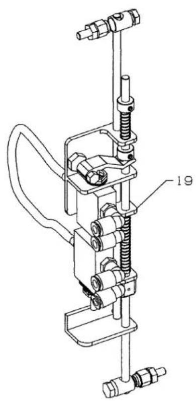
natural_image
Technical line drawing of a mechanical clamp or clamping device with no visible text or symbolsREAR ROLLER & PRESSER FOOT PNEUMATIC COMPONENTS & TREADLE SWITCH
| Ref. | Amt. | ||
| No. | Part No. | Description | Req. |
- 29476UE Pneumatic Assembly Kit .... 1
- 29476UD Puller Shaft Air Cylinder Assembly 1
- 671A35 Air Cylinder 1
- 660-219AT Roll Pin 1
- 35877AN Puller Shaft 1
- 29476TE Presser Bar Air Assembly 1
- 671A146-1 Air Cylinder 1
- 660-219AT Roll Pin 1
- 35822AH Presser Bar Shaft 1
*10. 35886M Washer, Fiber 1/3 - 671A256A Adapter, aircylinder 1
- 671A254 Adapter,aircylinder 1
- 35886H Washer, neoprene 1
- 35833R Collar, clamp 1
- SS7151310TP Screw 1
- 35886J Washer, neoprene 1
- 35833S Collar, clamp 1
- SS7111120TP Screw 1
- 29476SE Treadle Switch 1
- 671F81C Elbow Fitting 4
*Add washer(s) (Use 0-3 washers Max.) as necessary to position air cylinder properly to avoid air line fitting interference
text_image
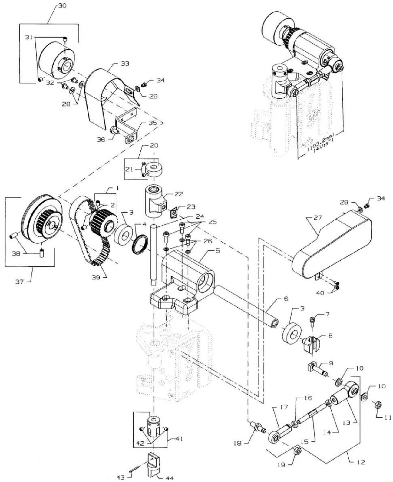
Technical diagram of an industrial machine with numbered components and assembly linesPULLER DRIVE ASSEMBLY
| Ref. | Amt. | ||
| No. | Part No. | Description | Req. |
- 35877AB Upper Sprocket 1
- 22894J Set Screw 2
- 660-974 Bearing 2
- 660-675 Load Ring 1
- 35844F Upper Shaft Housing 1
- 35874V Upper Shaft 1
- 22795 Adjusting Screw 1
- 34776L Shaft Head 1
- 51236C Crank Stud 1
- 99622A Washer 2
- 269 Nut 1
- 29476EE Connecting Rod Assembly 1
- 35877AE Rod End Bearing 1
- 35887AK Nut 1
- 35845E Connecting Rod 1
- 35887AJ Nut, left handed 1
- GR-35844W Rod End Bearing 1
- 35837X Stud 1
- 35887AK Nut 1
- 35877AG Collar, clutch shaft 1
- 22894W Set Screw 2
- 35877AH Clutch Shaft Housing 1
- 35837W Bearing Guide 1
- 35877AF Shaft, clutch 1
- 22653B12 Screw, upper shaft housing 3
- 53634C Washer 3
- 35882S Cover, connecting rod 1
- 20 Washer 2
- 80040-1 Washer 2
- 35821T Handwheel.... 1
- 22894C Screw 2
- 22569D Screw, mounting 2
- 35882F Cover,pullerbelt 1
- 73X Screw, belt cover 1
- 35883AX Bracket 1
- SS6120930TP Screw 1
- 35821W Main Shaft Pulley Assembly 1
- 22894E Set Screw 2
- C50042AG Timing Belt 1
- 22768 Screw 2
- 35876AH Feed Roller Connection, rear 1
- 22894P Screw 2
- 660-219 Roll Pin 1
- 54279 Feed Roller Drive Floating Connection 1
text_image
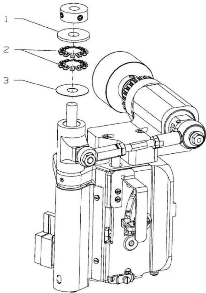
Technical diagram of a mechanical assembly with numbered parts for identification
natural_image
Technical line drawing of a mechanical device with gears and housing (no text or symbols)| Ref. | Amt. | ||
| No. | Part No. | Description | Req. |
- 50377AE Disc 1
- 661-261 Cup Spring 2
- 35886K Washer.... 1
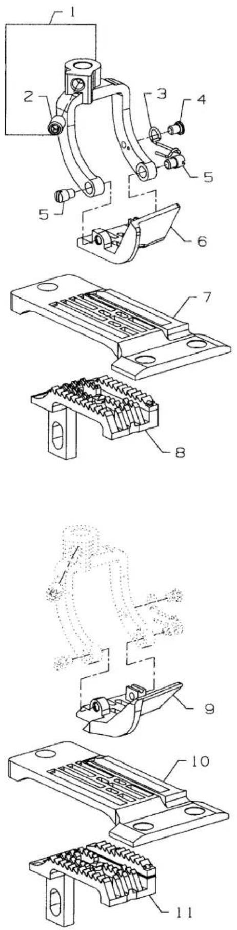
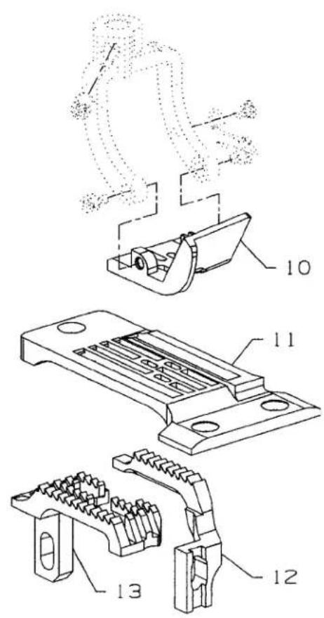
SEWING PARTS FOR PLAIN FEED
| Ref. | Amt. | ||
| No. | Part No. | Description | Req. |
- 35830DY Presser Foot Fork 1
- 22894BJ Screw 1
- 35830K Spring 1
- 22599 Screw 1
- 22845A Screw 2
- 35820BQW9 Presser Foot, for Style 35800BQWG9 1
- 35824BQW9 Throat Plate, for Style 35800BQWG9 1
- 35805BQW9 Main Feed Dog, for Styles 35800BQWG9 1
- 35830BXW8 Presser Foot, for Styles 35800BWDRG8 1
- 35830BXW9 Presser Foot, for Styles 35800BWDRG9 1
- 35824DQW8 Throat Plate, for Styles 35800BWDRG8 1
- 35824DQW9 Throat Plate, for Styles 35800BWDRG9 1
- 35805BRW8 Main Feed Dog, for Styles 35800BWDRG8,9 1

SEWING PARTS FOR DIFFERENTIAL FEED
| Ref. | Amt. | ||
| No. | Part No. | Description | Req. |
- 35830DY Presser Foot Fork 1
- 22894BJ Screw 1
- 35830K Spring 1
- 22599 Screw 1
- 22845A Screw 2
- 35830DWW8 Presser Foot, for Styles 35800BWWG8, BWWPG8 1
- 35830DWW9 Presser Foot, for Styles 35800BWWPG9 1
- 35830DN8 Presser Foot, for Style 35800 BWDNG8 1
- 35830DN9 Presser Foot, for Style 35800 BWDNG9 1
- 35824DX8 Throat Plate, for Stlyes 35800BWWG8, BWWPG8, BWDNG8 1
- 35824DX9 Throat Plate, for Styles 35800BWWPG9, BWDNG9 1
- 35826DX Differential Feed Dog, for Styles 35800 BWWG8, 9, BWWPG8, 9 .... 1
- 35826ED Differential Feed Dog, for Styles 35800 BWDNG 8, 9 .... 1
- 35805DX Main Feed Dog, for Styles 35800 BWWG8, 9, BWWPG8, 9 .... 1
- 35805EB8 Main Feed Dog, for Styles 35800 BWDNG8, 9 1
- 35820BQW9 Presser Foot, for Style 35800 BLWG9 1
- 35824BQW9 Throat Plate, for Style 35800 BLWG9 1
- 35826DLW9 Differential Feed Dog, for Style 35800 BLWG9 1
- 35805DLW Main Feed Dog, for Style 35800 BLWG9 1
text_image
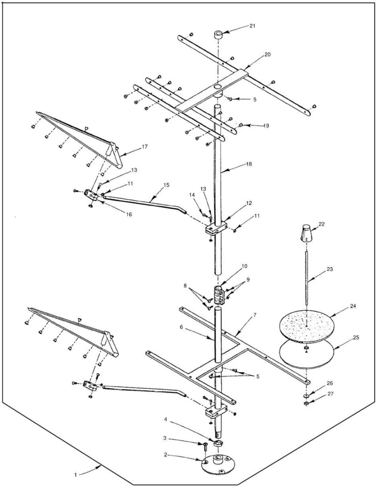
Technical diagram of a mechanical device with numbered components, likely an antenna or support structure.P191-94
THREAD STAND
| Ref. | Amt. | ||
| No. | Part No. | Description | Req. |
- 21101S7 Thread Stand, complete 1
- Thread Stand Base 1
- Screw 3
- Nut 1
- Screw 4
- Thread Stand Rod, short 1
- Base Bracket 1
- Screw 2
- Nut 2
- Joint 1
- Nut 8
- Holder, large 2
- Screw 6
- Screw, long 2
- Thread Guide Rod 2
- Holder, thread guide 2
- Thread Guide 2
- Thread Stand Rod, long 1
- Thread Eyelet 34
- Thread Guide 1
- Cap 1
- Spool Retainer 7
- Spool Pin 7
- Felt Disc 7
- Support Disc 7
- Spring Washer 7
- Nut 14

text_image
Technical diagram showing exploded view of six different screwdriver tools with numbered parts labeled 1 through 6.P186-94
ACCESSORIES
Ref. Part
Amt.
No. No.
Description
Req.
- TT85 Wrench, for looper avoid 1
- 21388AZ Wrench, for feed bar.... 1
- 21227AR Needle Head Torque Rod 1
- 660-240 Thread Tweezers.... 1
- 21201 Screwdriver 1
- 28604R Oil Can (not shown) 1
- 660-1012 Oil Nozzle (not shown) 1
- 660-457 Plastic Cover (not shown) 1
- WR56 Allen Wrench, size 1/4" (not shown) 1
- WR58 Allen Wrench, size 3/8" (not shown) 1
- WR60 Allen Wrench, size 1/2" (not shown) 1
- 39899A Threading Wire 1
NUMERICAL INDEX OF PARTS
| Part No. | Page No. | Part No. | Page No. | Part No. | Page No. | Part No. | Page No. |
| 109 | 49 | 22653E-24 | 23 | 23424F | 27, 31 | 35792T | 49 |
| 12934A | 21 | 22711 | 21 | 23424S | 27, 31 | 35796B | 25, 31 |
| 14649 | 47 | 22729C | 39, 41 | 23424T | 27, 31 | 35796C | 25, 31 |
| 15438C | 33 | 22729C | 43, 45 | 23425T | 27, 31 | 35805BQW9 | 57 |
| 18 | 39, 41, 43 | 22729D | 43 | 255 | 49 | 35805BRW8 | 57 |
| 20 | 53 | 22730 | 21 | 258 | 39 | 35805BRWH9 | 57 |
| 21101S7 | 61 | 22733A | 27 | 258A | 43, 45 | 35805DLW | 59 |
| 21201 | 62 | 22733B | 21 | 269 | 39, 41, 43, 53 | 35805DW18 | 59 |
| 21227AR | 62 | 22733G | 41, 45 | 27-435BLK | 25, 31 | 35805DX | 59 |
| 21237ES | 47 | 22738 | 47 | 28604R | 62 | 35805EB8 | 59 |
| 21388AZ | 62 | 22743 | 39 | 29101G | 39 | 35808AY | 43, 45 |
| 21756G | 35, 37 | 22747 | 25, 31 | 29103T | 41 | 35809AY | 43, 45 |
| 22504C | 41 | 22747 | 39, 41 | 29103U | 41 | 35809BY | 43, 45 |
| 22513D | 31, 33 | 22752B | 43 | 29105BH | 23 | 35815C | 35, 37 |
| 22516A | 21 | 22758C | 47, 49 | 29105BL | 23 | 35816 | 35, 37 |
| 22517 | 49 | 22758E | 33 | 29472AA | 35 | 35817S | 33 |
| 22519 | 41 | 22759A | 21 | 29472AC | 35, 37 | 35818CB-8 | 33 |
| 22519F | 35, 37 | 22760A | 27, 31 | 29472AD | 37 | 35818CB-9 | 33 |
| 22524 | 25, 29, 33 | 22764 | 39 | 29476EE | 53 | 35820BQW8 | 57 |
| 22526 | 43, 45 | 22766 | 23, 29 | 29476SE | 51 | 35820BQW9 | 57 |
| 22526B | 25 | 22768 | 33, 39 | 29476TE | 51 | 35820BQW9 | 59 |
| 22528 | 41 | 22768 | 41, 53 | 29476UD | 51 | 35821T | 53 |
| 22539AL | 27, 29 | 22784F | 49 | 29476UE | 51 | 35821W | 53 |
| 22539C | 27 | 22791E | 25, 31 | 29476YR | 33 | 35822AE | 33, 49 |
| 22539H | 27 | 22795 | 53 | 29478AH | 43 | 35822AH | 51 |
| 22539T | 23 | 22797 | 35, 37 | 29478AJ | 43 | 35822W | 35, 37 |
| 22560A | 29, 45 | 22798 | 25, 29, 31 | 29478BD | 39 | 35824BQW8 | 57 |
| 22561A | 25 | 22804 | 41 | 29478CZ | 29 | 35824BQW9 | 57 |
| 22562A | 43, 45 | 22829 | 23 | 29478DV | 41 | 35824BQW9 | 59 |
| 22564 | 35, 37 | 22839D | 49 | 29478DZ | 43, 45 | 35824DQW8 | 57 |
| 22564 | 43, 45 | 22845A | 57, 59 | 29478EB | 41 | 35824DQW9 | 57 |
| 22564B | 21, 27 | 22845M | 41 | 29478EC | 45 | 35824DW18 | 59 |
| 22564J | 29 | 22849 | 27, 31 | 29478ED | 47 | 35824DX8 | 59 |
| 22569B | 23 | 22849A | 25, 27 | 318 | 33 | 35824DX9 | 59 |
| 22569D | 53 | 22849A | 29, 31 | 34776L | 53 | 35825AC | 39, 41 |
| 22570 | 23 | 22874C | 39 | 35722AF | 43, 45 | 35826CB | 47 |
| 22570A | 23 | 22894AA | 41 | 35723C | 35, 37 | 35826DLW9 | 59 |
| 22571A | 27 | 22894AM | 35, 37 | 35731A | 33 | 35826DX | 59 |
| 22571B | 35, 37 | 22894BJ | 57, 59 | 35736A | 39 | 35826DZ | 47 |
| 22572 | 39 | 22894C | 47, 53 | 35736B | 39 | 35826ED | 59 |
| 22572B | 45 | 22894E | 53 | 35751 | 43 | 35826X | 47 |
| 22580A | 39 | 22894F | 23 | 35751B | 43 | 35829AJ | 33 |
| 22580D | 35, 37 | 22894J | 35, 37 | 35751F | 43 | 35830BXW8 | 57 |
| 22585A | 35, 37 | 22894J | 49, 53 | 35751G | 43, 45 | 35830BXW9 | 57 |
| 22585A | 49 | 22894K | 35, 37 | 35761 | 35, 37 | 35830DN8 | 59 |
| 22585C | 31, 47 | 22894P | 41, 47, 53 | 35761D | 23 | 35830DN9 | 59 |
| 22587B | 35, 37 | 22894U | 45 | 35763F | 35, 37 | 35830DWW18 | 59 |
| 22587E | 39, 41 | 22894W | 31, 37 | 35763G | 35, 37 | 35830DWW8 | 59 |
| 22587H | 41 | 22894W | 41, 45 | 35766A | 43 | 35830DWW9 | 59 |
| 22594 | 33 | 22894W | 47, 53 | 35766B | 45 | 35830DY | 57, 59 |
| 22596 | 29, 31 | 23420AY18-1/8 | 27, 31 | 35772S | 21 | 35830K | 57, 59 |
| 22596B | 35, 37 | 23421Y9-1/8 | 27, 31 | 35772T | 21 | 35832A | 49 |
| 22599 | 57, 59 | 23422AY18-1/8 | 27, 31 | 35781D | 23 | 35833R | 51 |
| 22653B12 | 53 | 23424AA | 27, 31 | 35792 | 49 | 35833S | 51 |
NUMERICAL INDEX OF PARTS
| Part No. Page No. | Part No. Page No. | Part No. Page No. | Part No. Page No. |
| 35834AB......41 | 35853AA......21 | 35883H......25 | 35897CC......35,37 |
| 35834AC......41 | 35853AD......43 | 35883J......25 | 35897CH......37 |
| 35834G......39 | 35853AJ......43,45 | 35883M......25 | 35897CK......33 |
| 35834N......39 | 35853AK......43,45 | 35883N......29 | 36204B......21 |
| 35834R......39 | 35853V156......43,45 | 35883P......29 | 36229A-1......29 |
| 35834U......39 | 35853W......21 | 35883R......31 | 36229A1......25 |
| 35834V3......39 | 35853Y......21 | 35883T......29 | 36234C......41 |
| 35834W......41 | 35853Z......21 | 35883U......31 | 36234F......41 |
| 35834X......41 | 35854A......33 | 35884E......25 | 36234G......41 |
| 35835B......39,41 | 35854B......33 | 35884F......25 | 36234M......41 |
| 35835F......47 | 35856Y......29 | 35884H......25 | 36236A......41,45 |
| 35836......39 | 35860D......23 | 35884L......27 | 36236B......45 |
| 35836A......41 | 35860E......23 | 35884R......25,29 | 36236C......45 |
| 35836B......41 | 35862A......35,37 | 35884S......33 | 36236G......41 |
| 35836C......45 | 35864F......35,37 | 35884T......33 | 36236H......41,45 |
| 35837A......43 | 35866......43,45 | 35886B......27 | 36236J......41 |
| 35837N......43 | 35866A......23 | 35886C......27 | 36236K......41 |
| 35837P......33 | 35866B......23 | 35886H......51 | 36236L......41 |
| 35837W......53 | 35866C......23 | 35886J......51 | 36237......41 |
| 35837X......53 | 35870......33 | 35886K......55 | 36237A......41 |
| 35838A......33 | 35871A......23 | 35886M......51 | 36237E......29 |
| 35838B......33 | 35871B......23 | 35887AE......21 | 36237H......29 |
| 35841B......39 | 35873AJ......47 | 35887AF......23 | 36237J......29 |
| 35842......43 | 35873AK......47 | 35887AG......21 | 36237K......29 |
| 35842H......43 | 35874V......53 | 35887AJ......53 | 36237L......29 |
| 35843B......39 | 35875AA......47 | 35887AK......53 | 36238......29 |
| 35843C......49 | 35875X......47 | 35887M......21 | 36238E......29 |
| 35843D......33,49 | 35875Y......47 | 35887R......21 | 36244......41 |
| 35844......39 | 35875Z......47 | 35887X......21 | 36244A......41 |
| 35844C......39 | 35876AH......53 | 35887Z......23 | 36244D......23 |
| 35844F......53 | 35876U......23 | 35888N......21 | 36249A......29 |
| 35844N......33 | 35877AA......47 | 35888T......21 | 36249B......45 |
| 35844T......33 | 35877AB......53 | 35889G......33 | 36256B......27,31 |
| 35844Y......39 | 35877AD......33 | 35889H......23 | 36261A......35,37 |
| 35844Z......39 | 35877AE......53 | 35890E......23 | 36278C......45 |
| 35845D......39 | 35877AF......53 | 35890Q......23 | 36280N......49 |
| 35845E......53 | 35877AG......53 | 35890R......23 | 36280S......49 |
| 35846......39 | 35877AH......53 | 35892A......47 | 36280T......49 |
| 35846B......39 | 35877AM......33,47 | 35893G......21 | 36280U......47 |
| 35847E......39 | 35877AN......51 | 35893H......21 | 36280V......47 |
| 35847X......35,37 | 35880L......49 | 35894K......35,37 | 36280W......49 |
| 35848B......43,45 | 35880N......49 | 35894V......35,37 | 36282......31 |
| 35848D......43,45 | 35880P......49 | 35895V......43,45 | 36283C......31 |
| 35848E......43,45 | 35882F......53 | 35895W......35,37 | 36284......25,29 |
| 35849B......43 | 35882J......33 | 35895Y......35,37 | 36284C......29 |
| 35849C......45 | 35882K......33 | 35895Z......35,37 | 36284E......31 |
| 35850B......25 | 35882S......53 | 35896B......31 | 36284F......31 |
| 35850C......25 | 35882T......33 | 35896D......33 | 36284Z......31 |
| 35850G......27,31 | 35883A......25 | 35897AX......27 | 36286......29 |
| 35851......43 | 35883AA......29 | 35897BM......35 | 36286B......29 |
| 35851A......43 | 35883AL......23 | 35897BU......35,37 | 36290B......23 |
| 35851G......43 | 35883AX......53 | 35897BV......35,37 | 36292K......49 |
| 35851P......45 | 35883E......25 | 35897BW......35,37 | 36292M......49 |
| 35851S......45 | 35883G......25,31 | 35897BY......35,37 | 36292N......49 |
NUMERICAL INDEX OF PARTS
| Part No. Page No. | Part No. Page No. | Part No. Page No. |
| 36292Q .....49 | 660-457 .....62 | SS7111410TP .....33 |
| 36293B .....21 | 660-548 .....39 | SS7111410TP .....49 |
| 36293F .....21 | 660-675 .....53 | SS7121410TP .....33 |
| 36293G .....31 | 660-764 .....23 | SS7151310TP .....51 |
| 36298G .....49 | 660-935 .....23 | SS8080310TP .....39 |
| 36298H .....49 | 660-974 .....53 | SS8120410SP .....33 |
| 376 .....39 | 661-150 .....31 | TT85 .....62 |
| 39141 .....43 | 661-261 .....55 | W56392F .....49 |
| 39592AK .....49 | 661-348 .....23 | WC50092S .....49 |
| 39899A .....62 | 664F-16 .....33 | WO3 .....33, 35, 37, 41 |
| 41071G .....21 | 666-149 .....35, 37 | WR56 .....62 |
| 41255B .....41 | 666-338 .....35, 37 | WR58 .....62 |
| 41355U .....39 | 666-340A .....33 | WR60 .....62 |
| 43246 .....39 | 666-47 .....39 | WZ0641510KP .....33 |
| 43296 .....33 | 667D-16 .....25, 29 | |
| 50-458BLK .....43, 45 | 671A146-1 .....51 | |
| 50311C .....23 | 671A254 .....51 | |
| 50377AE .....55 | 671A256A .....51 | |
| 50377L .....47 | 671A35 .....51 | |
| 51054A .....35, 37 | 671F81C .....51 | |
| 51236C .....53 | 73A .....21, 27, 31 | |
| 51292F14 .....49 | 73C .....47 | |
| 51292F4 .....49 | 73X .....53 | |
| 51758 .....25 | 77 .....35, 37, 41 | |
| 531 .....25, 27, 29, 31 | 80040-1 .....53 | |
| 53634C .....53 | 8372A .....23, 27 | |
| 538 .....29, 39 | 86 .....47 | |
| 54274C .....47 | 87A .....29 | |
| 54279 .....53 | 87U .....27, 31, 39, 41 | |
| 56341G .....43, 45 | 88 .....27, 39, 43, 47 | |
| 56354D .....35, 37 | 89 .....43 | |
| 57WB .....33 | 90 .....21, 25, 35, 37 | |
| 57WD .....33 | 93 .....21 | |
| 60078Z .....29 | 93A .....21 | |
| 6042A .....21, 33, 43 | 94 .....49 | |
| 605 .....33 | 9937 .....33 | |
| 62238A .....41, 45 | 99622A .....53 | |
| 660-1012 .....62 | 999-196 .....31 | |
| 660-1115 .....27, 29 | B3530555000 .....21 | |
| 660-1117 .....27, 31 | C067E .....23 | |
| 660-1132 .....23 | C50042AG .....53 | |
| 660-206 .....21 | CL21 .....23 | |
| 660-207 .....41, 45 | GR-35844W .....53 | |
| 660-212 .....21 | J87J .....25, 29 | |
| 660-219 .....53 | LA527 .....23 | |
| 660-219AT .....51 | SD0640241SP .....33 | |
| 660-219S .....49 | SD0640241SP .....49 | |
| 660-220 .....29, 41 | SS4091015SP .....33 | |
| 660-220 .....43 | SS6120930TP .....53 | |
| 660-221 .....39 | SS6121010SP .....33 | |
| 660-240 .....62 | SS7110510SP .....23 | |
| 660-254C .....49 | SS7110910TP .....37 | |
| 660-303 .....47 | SS7111120TP .....35 | |
| 660-310 .....43, 45 | SS7111120TP .....51 |
NOTES
NOTES
Union Special Corporation
Corporate Office
One Union Special Plaza
Huntley, IL 60142
Phone: 847·669·5101
Fax: 847·669·4454
Union Special GmbH
European Distribution Center
Raiffeisenstrasse 3
D-71696 Möglingen, Germany
Tel: 49•07141•247•0
Fax: 49•07141•247•100
JUKI CORPORATION
INTERNATIONAL SALES DIVISION
8-2-1, KOKURYO - CHO,