150-6TS - Sewing machine Union Special - Free user manual and instructions
Find the device manual for free 150-6TS Union Special in PDF.

User questions about 150-6TS Union Special
0 question about this device. Answer the ones you know or ask your own.
Ask a new question about this device
Download the instructions for your Sewing machine in PDF format for free! Find your manual 150-6TS - Union Special and take your electronic device back in hand. On this page are published all the documents necessary for the use of your device. 150-6TS by Union Special.
USER MANUAL 150-6TS Union Special
natural_image
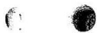
Vintage sewing machine with LEWIS brand label, shown from top-down view (no text or symbols on body)PARTS and INSTRUCTIONS
Catalogue 194-5
150 Class Machines
Models
| 150-1 | 150-9 |
| 150-5 | 150-15 |
| 150-6 | 150-16 |
| 150-6TS | 150-17 |
| 150-7 | 150-20 |
| 150-23 |
PRODUCT OF
UnionSpecial® MACHINE COMPANY
400 N. Franklin St.
Chicago, Ill. 60610
LEWIS CLASS 150 MACHINES
| INDEX | PAGE |
| Adjusting Chart | 13,14 |
| Adjusting Looper | 16-19 |
| Belt Loop Parts for 3/8" and 5/'6" wide Loops. | 93,94 |
| Cylinder Base Parts and their Adjustments. | 12 |
| Feeds. | 11,114 |
| Flared Skirts. | 11 |
| Feed Plates. | 115 |
| Feed Plate Holders. | 116 |
| Folders | 117 |
| General Instructions | 7-19 |
| Hemming Flared Skirts: Parts for, See Plate 8. Parts to adjust pressure of Feed Plates. | 11,53 |
| Instructions for Belt Loop Machine | 91,92 |
| Instructions - General. | 7-19 |
| Instructions for Ordering Parts | 5 |
| Instructions for Using Catalogue. | 5 |
| Model Numbers and Serial Numbers | 5 |
| Model 150-1 | 44-54 |
| Additional Parts for Model 150-1 | 54 |
| Plates for Model 150-1 | 46-53,110 |
| Model 150-5 | 56 |
| Additional Parts for Model 150-5 | 56 |
| See Plates for Model 150-1 | 46-53,110 |
LEWIS CLASS 150 MACHINES
| INDEX | PAGE |
| Model 150-6 | 58-60 |
| Additional Parts for Model 150-6 | 60 |
| Instructions for Model 150-6 | 57 |
| Plates for Model 150-6 | 59,111 |
| Model 150-6TS | 61-65 |
| Additional Parts for Model 150-6TS | 64,65 |
| Instructions for Model 150-6TS | 61 |
| Plates for Model 150-6TS | 63,111 |
| Model 150-7 | 66-71 |
| Additional Parts for Model 150-7 | 70,71 |
| Instructions for Model 150-7 | 67,68 |
| Plates for Model 150-7 | 69,113 |
| Model 150-9 | 72-76 |
| Additional Parts for Model 150-9 | 75-76 |
| Plates for Model 150-9 | 74,111 |
| Model 150-15 | 77-80 |
| Additional Parts for Model 150-15 | 80 |
| Plates for Model 150-15 | 79,111 |
| Model 150-16 | 81-93 |
| Additional Parts for Model 150-16 | 86-90,93 |
| Instructions for Model 150-16 | 91-92 |
| Plates for Model 150-16 | 82-85,112 |
| Model 150-17 | 96 |
| Additional Parts for Model 150-17 | 97 |
| See Plates for Model 150-1 | 46-53,111 |
| Model 150-20 | 81-94 |
| Model 150-23 | 98-109 |
| Additional Parts for Model 150-23 | 106-109 |
| Instructions for Model 150-23 | 98-100 |
| Plates for Model 150-23 | 102-105,113 |
| Needles | 8 |
| Oiling Machine | 9 |
| Parts List including all Models | 20-43 |


LEWIS CLASS 150 MACHINES
INDEX
PAGE
Plate Numbers - See Models. See below.....
Presser Feet....9,118,119
Regulating Length of Stitch 12
Ridge Forming Disc 9,10,120
Ridge Forming Disc Regulator 10
Retainer or Cloth Clamp 19,20
Speed of Machine 9
Serial Numbers and Model Numbers. 5
Thread 8
Threading Machine 7
Timing and Adjusting Charts.... 13,14
Unpacking Machine 7


LEWIS CLASS 150 MACHINES
INDEX
PLATES
| PLATE NO. | PAGE NO. | |
| 1 | Timing Chart. | 13 |
| 1A | Timing Chart. | 14 |
| 2 | Parts For Model 150-1 | 46 |
| 3 | Parts For Model 150-1 | 47 |
| 4 | Parts For Model 150-1 | 48 |
| 5 | Parts For Model 150-1 | 49 |
| 6 | Parts For Model 150-1 | 50 |
| 7 | Parts For Model 150-1 | 51 |
| 8 | Parts For Model 150-1 | 52 |
| 9 | Parts For Model 150-1 | 53 |
| 10 | Additional Parts For Model 150-6 | 59 |
| 11 | Additional Parts For Models 150-6, 150-6TS | 63 |
| 12 | Additional Parts For Model 150-7 | 69 |
| 13 | Additional Parts For Model 150-9 | 74 |
| 14 | Additional Parts For Model 150-15 | 79 |
| 15 | Additional Parts For Model 150-16 | 33 |
| 16 | Additional Parts For Model 150-16 | 84 |
| 17 | Additional Parts For Model 150-16 | 85 |
| 18 | Additional Parts For Model 150-23 | 102 |
| 19 | Additional Parts For Model 150-23 | 103 |
| 20 | Additional Parts For Model 150-23 | 104 |
| 21 | Additional Parts For Model 150-23 | 105 |
| 22 | Additional Parts For Models, 150-1 and 150-5 | 110 |
| 23 | Additional Parts For Models, 150-6, 150-9, 150-15 and 150-17 | 111 |
| 24 | Additional Parts For Model 150-16 | 112 |
| 25 | Additional Parts For Models, 150-7 and 150-23 | 113 |


INSTRUCTIONS FOR USING CATALOGUE
TO ORDER PARTS
The Model 150-1 Machine is the basic machine used in compiling this catalogue that is the majority of parts used in the Model 150-1, are used in all the models of the class 150 Machines.
Additional parts used to make each Model are listed under each model number.
To find a part needed, note model number on the machine for which the part is wanted, and the index will show the page number, referring to the model.
The Model No. is located on top of the head of the machine.
****************************************************************************************
The Serial No. of each machine is stamped in the arm under the top cover.
******************************************************************************************
State Model No. and Serial No. of machine when ordering parts.
Turn to the plate showing drawings of machine to obtain part number. If part cannot be located, then the part is common to Model 150-1, or to the model referred to at the bottom of the page of parts listed.
The parts listed and plate drawing in each model section are the additional parts used over the models referred to at the bottom of page of parts listed.
If part number is known turn to General parts list for description and best plate for locating part.
The plate drawings show only the standard parts such as presser feet, folders and etc. For parts other than standard, see lists on last pages of catalogue, also see plates, 22, 23, 24, and 25. Refer to index for following subjects:
Feeds.
Feed Plates.
Folders.
Presser Feet.
Ridge Forming Disc.


GENERAL INSTRUCTIONS FOR THE INSTALLATION, ADJUSTMENT, AND OPERATION OF LEWIS CLASS 150 MACHINES
UNPACKING MACHINE
To remove the machine from the box, take off the cover and remove the nails and screws that hold the brace blocks in position. Use a nail puller to avoid breaking the machine. These blocks are held by nails or screws driven through the outside of the box. The knee lifter is attached to the side of the box, and the other small parts will be found wrapped in a package. Be sure to look carefully through the material used for packing before destroying it, so that you will find all the parts and equipment that goes with the machine. Lift the machine out of the box very carefully to avoid breaking the tension studs as these parts project beyond the head of the machine.
Set up the machine; clean away accumulated lint and dust, especially from the looper.
Place the machine on the bench with the pulley lined up with the transmitter, and, assemble the knee lift lever to the machine. The machine should be set on the table so that the knee lift lever is 1/2" from the edge of the table.
Mark the three holes for the machine screws and bore for the screw holes; bore the hole for the belt; place the felt pad under the machine and fasten the machine to the table, using the three machine bolts that were used to hold the machine into the packing case.
HAND WHEEL
The top rim of hand wheel turns, when facing the pulley, away from the operator or clockwise. The pulley is 2" diameter at the pitch line of the belt groove.
THREADING
From the spool stand, pass the thread through the eye-let just back of the tension disc, then between the tension disc on the left side, then lift thread over the pin which passes through the tension discs; then through the pig-tail eyelet over the needle bar, then through the hole in the needle clamp, then through the eye of the needle.
REMOVING WORK
See that the needle is out of the cloth. Lower the feed plates and retract the disc and give the work a quick jerk which will break the thread.
We reserve the right to change specifications or designs at any time without incurring the obligation to install such changes on machines previously manufactured.
NEEDLE SIZES
The needles are furnished in the following sizes, order by number:
| Taper PointNot Scarfed | Taper Point 15^ Front Scarf | Sharp Point 15^ Front Scarf |
| 29-492 1/2 | 29-343 | 29-493 |
| 29-343 12 | 29-493 12 | |
| 29-344 | 29-494 | |
| 29-344 12 | 29-494 12 |
Ordinarily, sizes 29-343 12 and 29-344 will serve the purpose. A full range of needle sizes are, however, available to meet all requirements.
Use ONLY genuine LEWIS needles. Look for the copyrighted word "LEWIS" stamped on the shank of each needle.
THREAD
Use any good grade of left-twist three cord hard finish cotton thread in sizes 70 to 100. If silk thread is used, select either "00" or "000".
REGULATING DEPTH OF NEEDLE PENETRATION
The needle penetrating adjustment is located on top of the cylinder base of the machine and is a dial with graduations, showing the word "More" and indicates the direction in which to turn for raising the ridge forming disc for a deeper penetration; and the word "Less" which indicates the direction to turn the dial to obtain less needle penetration in the work.
SKIPPING STITCHES
Examine point of needle to see if it is blunt or turned over. Replacing needle will generally remedy skipping of stitches.
REPLACING NEEDLE
Insert needle into needle carrier as far as possible and tighten set screw. Needle should bear slightly on the needle guide.
IMPORTANT -- OIL MACHINE DAILY
SPEED
The LEWIS Class 150 machines can be operated up to 3000 stitches per minute. A speed of 1800 to 2000 stitches is recommended in starting a new machine or with a new operator. Speed may be increased to suit operator or class of work.
TIMING
All basic driving parts are properly timed with spot screws.
PRESSER FOOT
Place new needle in the needle carrier as far as possible and with the point directly over the needle guide adjust the foot up or down so that the point of the needle is under scant .010" tension. Observe that shank of needle passes over the needle guide freely.
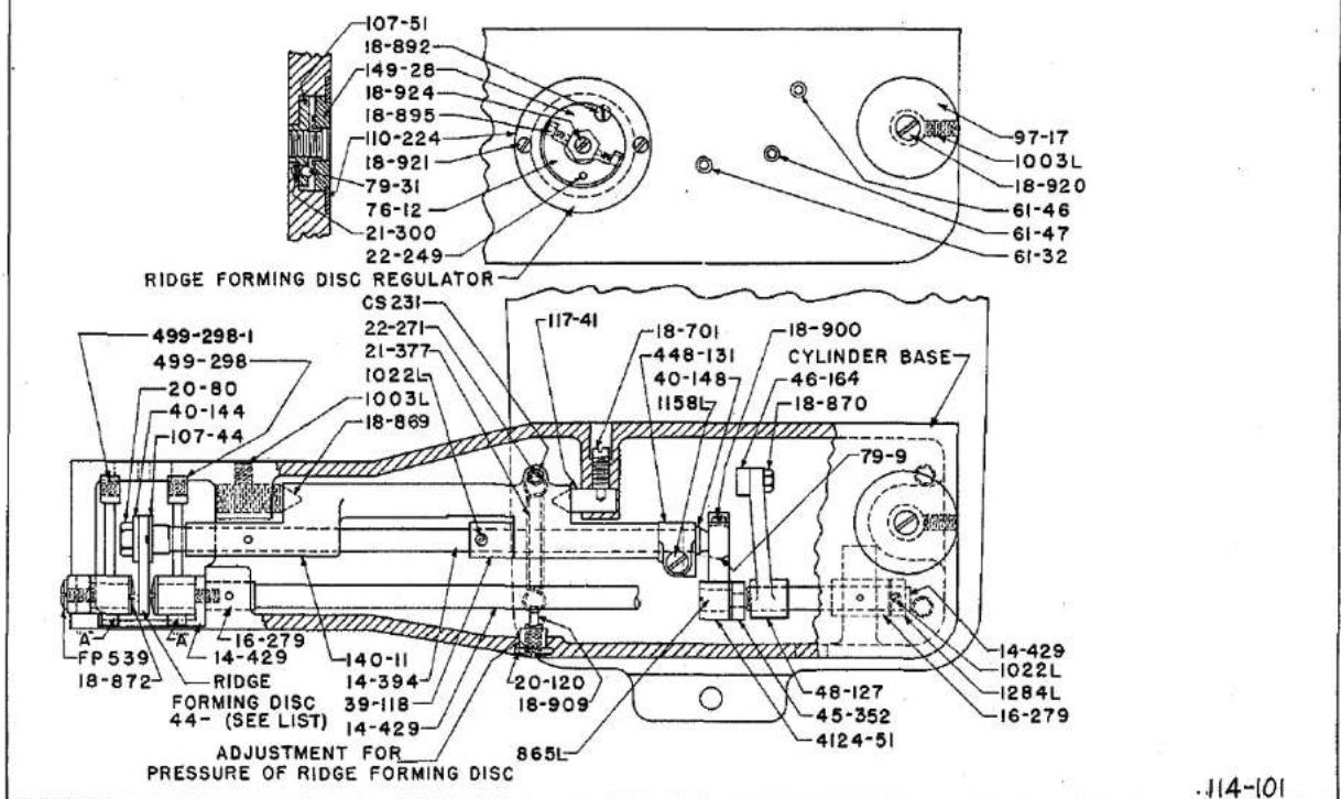
RIDGE FORMING DISC (Refer to Plate 1A)
The disc must be adjusted to be in the center of the slot in the presser foot, and so that the nose of the disc is set in relation to the needle, Models 150-1, 150-6, 150-6TS, 150-7, 150-17. For other models, refer to special instructions on model in question.
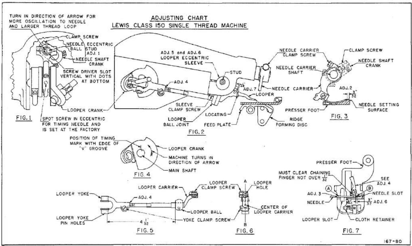
Before setting the disc be sure that there is no end play to the cradle 140-11. Any end play can be taken up by adjusting the pivot bearing screw 18-869, Set Screw 1003 must first be loosened and the tension of Spring 21-377 released.
Adjust Pivot Screw 18-869 just enough to take up play but the cradle must move very freely. Check by moving cradle by hand, then lock pivot screw in place by tightening set screw 1003 to lock 18-869 in place.
Adjust tension spring 21-377 with nut 20-120. Normal setting is when the end of screw for adjusting tensions 18-909 is even with the end of nut 20-120.
To adjust the disc to center of slot in the presser foot, loosen set screw 1022 in collar 39-118 and clamp screw 1158 in crank 448-131 and set disc to slot, at the same time set the disc so that when the point of the needle is at the center of the slot in presser foot and at center of the disc, the point of the needle will be 1/16" from where the small radius on nose of the disc joins the periphery of the disc. This setting is made when the disc is at its most advanced position. Tighten clamp screw 1158 in crank 448-131 and set screw 1022 in collar 39-118 and set the collar to take up all end play in the ridge forming disc shaft.
To remove the ridge forming disc, depress the left hand feed plate holder, remove the nut 20-80 on end of disc shaft and remove the washer 40-144 and disc. When reassembling the disc, care must be taken that the key in flange 107-44 engages the slot in the disc. Assemble the washer 40-144 and nut 20-80 and tighten firmly.
RIDGE FORMING DISC REGULATOR (Refer to Plate 1A)
The dialed regulator located on top of the Cylinder Base raises and lowers the ridge forming disc to get the correct needle penetration in the work being done to form a blind stitch. The word "More" indicates more depth, and "Less" indicates less depth of needle penetration.
The regulator also limits the amount that the disc can be raised in order to protect the needle point from striking the ridge forming disc. The adjustment is made by turning the regulator in the "More" direction as far as possible to stop pin inside of the regulator.
A needle must be in the needle carrier and in contact with the needle guide and point of needle over the ridge forming disc.

Now remove the set screw 18-924 (See Plate No. 1A) and adjust screw 18-923 that contacts the cradle 140-11 in which the ridge forming disc shaft is mounted and adjust so that the ridge forming disc will lift the needle off of the needle guide .010" which is equivalent to two thicknesses of newspaper. Re-assemble the 18-924 screw and set tightly to lock screw 18-923 in place. These two screws are located inside of the main hexagon headed adjusting screw 18-922.
The adjustment for the spring tension for correct pressure of ridge forming disc is made by turning nut 20-120, located in front of cylinder base, turn in clockwise direction to get more tension and in reverse direction for less tension.
FEED
The feed is adjustable relative to the presser foot by loosening the two binding screws holding the feed, and turning over the machine, away from you, until the feed motion is at the lowest point, then set the feed so that it is 1/32" below and parallel with the bottom of the presser foot, for light and medium weight materials; for heavy work, the feed must be brought below the presser foot about 3/64".
The feed is adjustable from three to eight stitches per inch.
FEED PLATES
The Feed Plates press the work against the bottom of the presser foot and feed, when on its feeding stroke by two springs.
There must be enough pressure applied to hold the work from moving when the needle penetrates the material, for if the material moves with the needle, a loop will not be formed for the looper, resulting in skip stitches.
Check to see that Feed Plates clamp a piece of newspaper before point of needle penetrates material.
For sewing flared skirts with wide hems, the pressure applied for each feed plate can be varied so the machine will feed in the fullness in this type of hem if the operator holds back slightly on the hem.
ADJUSTING LENGTH OF STITCH
The stitch is regulated by the knob 426-47, Plate 3, located on top of the arm of the machine, near the head. First, open the top cover of the machine to observe the feed indicator on the shaft, with numerals which indicate the number of stitches per inch, press down the feed knob located on top of the machine, which will engage a slot in the feed mechanism; now turn the hand wheel over and away from you while holding the knob in the slot to lengthen stitch, and toward you to shorten stitch, and observe through the opening in the top of the arm, the number on the feed disc as you turn until the numeral, indicating the stitches per inch, is directly under the indicator.
CYLINDER BASE PARTS AND THEIR ADJUSTMENT (See Plate 1A)
The parts in the Cylinder Base and base of arm operate the ridge forming disc, depress the feed plate and retract the disc to insert and remove the work from the machine.
Parts in the Cylinder Base where possible are held in position with spot screws and a timing mark has been milled in the bracket 50-222. Parts assembled in this bracket that have timing marks that must match the timing mark in the bracket are Eccentric 433-151 and Gear 27-165.
Bracket 50-222 can be removed from the machine by removing Stud 17-145 which will disconnect the end of Connecting Rod 447-118 from Lever 45-352. Next remove the three Screws 18-664 and take bracket from the base by slipping the headless bearing Stud 865 out of the hole in Ball Joint 4124-51.
Gear 27-166 and Eccentric 433-151 are held on to the Shaft 14-458 by the Spot Screws 1025 and 18-624, therefore when assembling, if the gear teeth are engaged so that the timing marks all coincide, the machine will function properly.
Crank 448-131 is clamped to the disc shaft and is used to adjust the ridge forming disc. (See Plate IA)
Crank 48-127 is for adjusting Shaft 14-429 for depressing feed plates. The adjustment is made through a hole in front of cylinder base. Loosen screw CS 331 in crank 48-127 and with feed plates in contact with presser foot, adjust surface (A) of 14-429 so that two thicknesses of newspaper will just pinch against the contact surface of feed plate holders. See (A) plate 1A. Be sure feed plates are in contact with bottom of presser foot.
Check the above setting by depressing the feed plates as far as possible, and turn over hand wheel, and see that crank, 48-127 turns without interfering with adjacent parts.
text_image
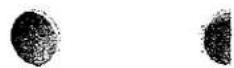
TURN IN DIRECTION OF ARROW FOR MORE OSCILLATION TO NEEDLE AND LARGER THREAD LOOP ADJUSTING CHART LEWIS CLASS 150 SINGLE THREAD MACHINE CLAMP SCREW NEEDLE ECCENTRIC BALL STUD ADJ. 1 NEEDLE SHAFT CRANK SCREW DRIVER SLOT VERTICAL WITH DOTS AT BOTTOM LOOPER CRANK SPOT SCREW IN ECCENTRIC FOR TIMING NEEDLE AND IS SET AT THE FACTORY FIG.1 ADJ. 5 and ADJ. 6 LOOPER ECCENTRIC SLEEVE STUD ADJ. 4 SLEEVE CLAMP SCREW LOCATING FEED PLATE LOOPER BALL JOINT FIG.2 NEEDLE CARRIER CLAMP SCREW NEEDLE CARRIER SHAFT NEEDLE CARRIER ADJ. 7 LOOPER PRESSER FOOT RIDGE FORMING DISC FIG.3 NEEDLE SETTING SURFACE POSITION OF TIMING MARK WITH EDGE OF "V" GROOVE MOHINE TURNS IN DIRECTION OF ARROW MAIN SHAFT FIG.4 LOOPER CRANK LOOPER CARRIER A LOOPER CLAMP SCREW LOOPER HOLE LOOPER BALL CENTER OF LOOPER CARRIER B LOOPER YOKE ADJ. 4 LOOPER YOKE PIN HOLES 4 32 FIG.5 MOHINE TURNS IN DIRECTION OF ARROW FIG.6 MUST CLEAR CHAINING FINGER NOT OVER 32 SEE ADJ. 4 A B NEEDLE SLOT NEEDLE 3 32° ADJ. 6 LOOPER SLOT CLOTH RETAINER FIG.7 167-80
text_image
TIMING & ADJUSTING CHART LEWIS CLASS 150 SINGLE THREAD MACHINE FEED PLATE HOLDER ( LEFT ) 40-144 20-80 RIDGE FORMING DISC A 140-11 14-429 21-377 1003L 21-377 18-869 1158L 448-131 49-127 1022L- 39-118- 18-909- 20-120 865L 4124-51 18-924 18-922 SCREW DRIVER HOLE IN CYLINDER BASE RIDGE FORMING DISC REGULATOR 18-923 14-458 1025L CS33I 48-127 REAR WALL OF MACHINE 1284L 18-624 50-222 433-151 21-344 39-117 PRESSURE SPRINGS 21-344 18-664 14-395 39-105 27-166 50-222 27-165 45-352 17-145 447-118 48-150 KNEE LIFTER ROD 14-400 -125PLATE 1A


Crank 48-150 is for adjusting the position of the Knee Lifter in best position for operator.
Collar 39-105 is used for taking up end thrust of Shaft 14-395 and setting tension of Spring 21-344 for returning ridge forming disc and feed plates to sewing position.
Collar 1284 is used for taking up end thrust of Shaft 14-429.
Collar 39-117 is used to take up end thrust of knee press Shaft 14-400 and for setting tension of Spring 21-344 for holding knee lifter out of contact with depressing lever.
TIMING THE MACHINE
Needle:
A No. 4 taper point needle should be used when adjusting the needle position.
To secure the correct adjustment for the needle swing the following steps must be taken and settings made. (See adjusting chart). Plate 1.
Adjustment 2
To set the point of the needle in the correct position when the needle is at the extreme end of its stroke towards the hand wheel, the following steps must be taken: Turn the machine over until screw driver slot in the needle eccentric ball stud is straight up and down with the two dots at the bottom. See Figure 1. With the machine in the above position, loosen the needle carrier clamp screw and move the needle carrier so that the point of the needle is 1/16" to 3/32" from the edge of the needle setting surface. See Figure 3. Tighten the needle carrier clamp screw.
Adjustment 3
To set the needle in the correct position in the needle slot - See Figure 7 - the following steps and setting must be made: Loosen the needle carrier clamp screw and move the needle carrier - See Figure 2 - in or out so that the rear side of the needle will just clear the needle slot at "A" - See Figure 7 - and clear the needle shoulder of presser foot at "B" about .005". Check to see that the setting for the needle point still is 1/16"
to 3/32" from the needle setting surface of presser foot. Tighten the needle carrier clamp screw.
LOOPER
The correct setting of the looper is of the greatest importance. (See adjusting chart). Plate 1.
The looper is mounted in the looper carrier assembly - allow 1/64" space between looper shoulder and end of looper carrier - See Figure 2 - and the correct assembling of this unit must be understood in case for any reason it is necessary to remove or replace this assembly.
The looper carrier assembly consists of:
Looper Yoke - in which are the looper yoke pin holes Clamp Screw Looper Ball Looper Carrier
The looper carrier and looper yoke are set before assembling these parts into the machine. Now, the looper ball is positively located on the shaft of the looper carrier by a spot screw. The looper carrier is assembled to the looper yoke so that the distance from the edge of the looper yoke pin hole nearest the looper ball, to the side of the looper ball nearest to the looper yoke, will be 4-1/32". See adjusting chart - Figures 5 and 6.
The looper has means for the following adjustments, which, for reference to the drawing, are numbered as follows:
Adjustment 4
Means for adjusting the looper position on the right hand side or when the looper is taking the loop from the needle.
Adjustment 5
Means for adjusting the looper position on the left hand side or when the needle is between the prongs of the looper.
Adjustment 6
Means for adjusting the position of the looper from left to right or right to left.
Adjustment 7
Means for adjusting the looper in and out.
Before setting the looper, the looper carrier assembly must be in accordance with instructions for Figure 5 and Figure 6 and the needle setting must be as described in adjustments 1, 2 and 3.
The looper is and can be timed at only one place.
TIMING THE LOOPER
Timing the looper is relative to the needle. Loosen the two set screws on the looper crank. To time the looper, turn the machine over by the hand wheel by turning the hand wheel towards the rear of the machine until the screw driver slot in the needle eccentric ball stud is straight up and down with the two dots at the bottom - See Figure 1, adjustment 1.
There is a "V" notch cut in the main shaft of the machine which will be at the top of the shaft.
There is a timing mark on the looper crank - See Figure 4.
Turn the looper crank until the timing mark on the crank coincides with the left hand edge of the "V" on the main shaft. This timing mark will not vary more than 1/32" plus or minus relative to the edge of the "V".
Clamp the looper crank to the main shaft of the machine with the two set screws.
ADJUSTING AND SETTING THE LOOPER
To secure the correct adjustment of the looper, the following steps should be taken and in the same sequence as here given:
The looper is first adjusted as the looper is taking the loop from the needle.
The position for the long prong of the looper is to have the point of this prong 3/32" from the inner end of the needle eye and the point of the long prong just clearing the scarf of the needle.
To secure this setting, the following steps and adjustments are taken and made:
Turn the hand wheel in clockwise direction; that is, the top of the hand wheel will be moved away from the operator very slowly until the long prong of the looper is over the center line of the needle.
Loosen the looper yoke clamp screw - See Adjustment 4, Figures 2 and 5 - and roll the looper until the long prong of the looper just clears the scarf of the needle.
Loosen the sleeve clamp screw - See Figure 2 - this permits the looper eccentric sleeve to be moved from left to right - and slide the looper eccentric sleeve - Figure 2, adjustment 6, until the long prong of the looper is 3/32'' from the inner end of the needle eye.
Check to see that point of the long prong of the looper just clears the scarf of the needle. Tighten the looper yoke clamp screw - See Figure 5, and the looper eccentric sleeve clamp screw - See Figure 2.
Continue to rotate the hand wheel in clockwise direction, until the short prong of the looper is at nearest point when passing chaining finger, if foot has chaining finger, not exceeding 1/32" - See Figure 7. If the short prong does not clear the chaining finger, or if the clearance is greater than 1/32", then the previous adjustments have not been correctly made, and these should be re-made.
Continue to rotate the hand wheel in clockwise direction until the short prong of the looper has passed the edge of the looper slot in the foot. If the short prong of the looper does not enter the looper slot in the foot, adjust so that the short prong will clear the edge of the looper slot in the foot by moving the looper eccentric sleeve - Adjustment 6, Figure 2. Move the looper eccentric sleeve the least amount possible so that the short prong clears the edge of the looper slot.
Care must be taken now as the needle may strike the crotch of the looper when the needle should be entering between the prongs of the looper.
Continue to turn the hand wheel in clockwise direction until the point of the needle should enter between the prongs but instead of so doing strikes the crotch of the looper - the following corrective steps are required:
Loosen the two set screws on the looper crank - See Figure 4, and turn crank slightly in a clockwise direction until the needle does not strike the crotch. Tighten the set screws.
The needle must enter between the prongs of the looper, clearing the two prongs about an equal amount.
In case the needle should not enter about midway of the two prongs - to correct this, loosen the sleeve clamp screw - Figure 2, and turn the looper eccentric sleeve - Adjustment 5, Figure 2, until the prongs of the looper are about an equal distance from the needle. When this setting has been made, tighten the sleeve clamp screw - See Figure 2.
Continue to rotate the hand wheel in a clockwise direction until the point of the long prong of the looper is over the center line of the needle. Check to see that the point of the long prong of the looper is 3/32" from the inner end of eye of the needle and that the point of the long prong just clears the scarf of the needle. In case the above conditions do not exist, they must be corrected - this is done as described in the fifth to tenth paragraphs inclusive under the heading "ADJUSTING AND SETTING THE LOOPER". Be sure to roll the looper - Adjustment 4, Figure 5. Do not turn the looper eccentric sleeve.
The machine, as far as the looper and needle are concerned, is now ready to sew. Different material or different threads may cause a slight variation from the above adjustments. However, these adjustments will give the best results when padding or hemming the more heavy materials. When hemming silks and cotton, however, it may be advisable to set the point of the needle 1/16" from the needle setting surface on the presser foot - Figure 3, instead of 3/32", without changing the loop-er position by re-adjusting the needle ball stud - Adjustment 1, Figure 1 - the timing dots on the ball stud should be turned in direction towards the hand wheel to obtain slightly more throw to the needle resulting in a larger thread loop.
RETAINER OR CLOTH CLAMP
The Cloth Retainer located in the cloth opening of the presser foot must at all times be adjusted as close to the needles as possible and set relative to the ridge forming disc to firmly hold the work on to the disc while the needle is penetrating the material. If the work is carried along with the needle, no loop will form, resulting in missed stitches.
PARTS LIST FOR LEWIS CLASS 150 MACHINES
| Part No. | Plate | Description |
| 4-C114 | 20 | Work Plate (large) for Models 150-7 and 150-23 |
| 4-121 | 15,16 | Aluminum Work Plate attached to bracket 50-234 for Model 150-16, 150-20 |
| 4-126 | 8 | Work Plate (swing type) in 404-126 when end cover 32-264 is used. Models 150-1, 150-15 |
| 4-127 | - | Work Plate (swing type) in 404-127 when using 32-264 Model 150-9 |
| 6-56 | 22, 23, 24, 25 | Needle Guide |
| 6-70 | 17 | Needle Guide, Model 150-20 |
| 8-89 | 4 | Belt Guard |
| 8-122 | 16, 24 | Guard for right hand top knife, Model 150-16, 3/8"; Model 150-20, 5/16" |
| 8-123 | 15, 16, 24 | Guard for left hand top knife, Model 150-16, 3/8"; Model 150-20, 5/16" |
| 8-124 | 24 | Guard for right hand top knife in 5/16" belt loops, Model 150-16 |
| 8-125 | 15, 24 | Guard for left hand top knife for 5/16" belt loops, Model 150-16 |
| 8-128 | 16 | Guard for right hand top knife, Model 150-20, 3/8" |
| 8-129 | 15, 16 | Guard for left hand top knife, Model 150-20, 3/8" |
| 14-14 | 3 | Shaft for Needle Carrier 4118-24 |
| 14-260 | 8 | Shaft in Bracket 50-211 for swinging Work Plate 4-126, 4-127 |
| 14-394 | 5, 19, 20, 21 | Shaft for Ridge Forming Disc in Cylinder Base 150-1,-5,-6,-7,-9, 150-15,-17,-23 |
| 14-395 | 4, 6, 7 | Shaft in Base for Gear 27-165 |
| 14-400 | 6, 9 | Shaft for Knee Press |
| 14-429 | 4, 5, 6, 9 | Shaft in Base to depress Feed Plates for 150-1,-5,-7,-9,-15,-16,-17,-20, 150-23 |
| 14-432 | 2, 4 | Main Shaft |
| 14-434 | 10, 11 | Shaft in Base for Feed Plate Holders Models 150-6, 150-6TS |
| 14-435 | 10, 11 | Shaft for Ridge Forming Disc in Cylinder Base - Model 150-6TS |
| 14-440 | 20, 21 | Shaft for Crank 48-138 to shog disc Model 150-23 |
| 14-441 | 21 | Jack Shaft in Arm - Model 150-23 |
PARTS LIST FOR LEWIS CLASS 150 MACHINES
| Part No. | Plate | Description |
| 14-458 | 4,7,9 | Shaft in Base for oscillating disc Lever 45-352 |
| 16-39 | 3 | Needle Shaft Bushing Front End of Head |
| 16-148 | 3 | Needle Shaft Bushing, Rear end of Head |
| 16-194 | 3 | Bushing in Arm for 26-47 to change length of stitch |
| 16-196 | 2,4 | Bushing for Main Shaft 14-432 Head end of Arm |
| 16-214 | 17,22,24,25 | Bushing in Presser Feet for adjusting Cloth Retainer |
| 16-239 | 6 | Bushing in Base for Knee Lift Rod |
| 16-255 | 21 | Bushing (eccentric) in Arm for Adjusting Gear 27-215, use set screw CS317 |
| 16-279 | 2,5 | Bushing in Head for Eccentric Stud 17-114 for adjusting height of feed and in Cylinder Base for 14-429 |
| 16-317 | 2,4 | Bushing for Main Shaft, Hand Wheel End of Arm |
| 16-322 | 20,21 | Bushing in base for 14-440 for shogging disc Model 150-23 |
| 16-329 | 21 | Bushing for Main Shaft Hand Wheel end of Arm, Model 150-23 |
| 17-87 | 17,22,24,25 | Eccentric Stud in Bushing 16-214 for adjusting Cloth Retainer |
| 17-111 | 25 | Eccentric Stud for adjusting Crowns 126-43 and 126-47 on presser feet 405-514 and 405-558 |
| 17-113 | 25 | Stud for Crown 126-36 on Presser Foot 405-409-1 and 405-522 Model 150-7 |
| 17-114 | 2 | Eccentric Stud in Head for Link 446-118 |
| 17-145 | 4,6 | Stud in Lever 45-352 for Connecting Rods 447-118 and 447-125 |
| 17-146 | 2,3 | Stud for Looper Ball Joint Sleeve 70-53 |
| 17-149 | 2 | Stud in Looper Drive Crank 48-135 for Looper Bearing |
| 17-150 | 2,3 | Stud for Feed Lever in Head |
| 17-153 | 15,16,24 | Stud for Plunger Link 46-157 in Cylinder Base, Model 150-16,150-20 |
| 17-157 | 9 | Eccentric Stud for adjusting Latch for Disc Locking Mechanism |
| 18-38 | 4,15,24 | Screw for Indicator 155-9 and for attaching 110-236, 110-237 to trimmer bracket, Model 150-16 |
PARTS LIST FOR LEWIS CLASS 150 MACHINES
| Part No. | Plate | Description |
| 18-70 | 3 | Clamp Screw for needle carrier 4118-24 |
| 18-71 | 2 | Clamp Screw for looper yoke 449-27 |
| 18-74 | 3 | Spot Screw in 479-8 to locate on looper carrier 4118-15 |
| 18-C110 | 13,14 | Screw for attaching folder bracket 50-223 to presser feet 405-497, 405-537, 405-538, Models 150-9 and 150-15 |
| 18-121 | 8 | Screw in shaft 14-260 for work plate |
| 18-125 | 11 | Screw for Spring 21-332 Model 150-6TS |
| 18-C186 | 13,14 | Set Screw for collar 39-C255 for locating folders, Models 150-9, 150-15 |
| 18-261 | 13 | Screw for attaching 1733 L to 50-280 L |
| 18-270 | 17,22,24 | Screw in end of eccentric stud 17-87 |
| 18-277 | 8 | Screw in work plate for holding folders |
| 18-281 | 23 | Screws for attaching roll forming plate 110-230 to presser feet, Models 150-6 and 150-6TS |
| 18-292 | 22,23,25 | Screw for holding chaining fingers to presser feet |
| 18-295 | 10,11 | Bearing Screw for feed plate in cylinder base, Models 150-6 and 150-6TS |
| 18-307 | 3,17 | Screw for holding presser foot to brac- ket 50-160, and for 22-257, Model 150-16, -20 |
| 18-318 | 12,18,19, 21,25 | Screw for attaching ridge forming disc 44-275 to plunger 26-152 in cylinder base, Models 150-7 and 150-23 |
| 18-326 | 6 | Screw for clamping 39-117 collar to knee lift shaft in base of arm |
| 18-330 | 2,13,14 | Screw for cover 32-107 on head, screw for bracket 50-223, Models 150-9 and 150-15 |
| 18-345 | 25 | Screw for presser foot 405-409-1, 405-514, 405-522, 405-558 |
| 18-355 | 4 | Screw for 107-51 ridge forming disc regulator in cylinder base |
| 18-375 | 16 | Screws for top knives, Model 150-16, 3/8 inch; Model 150-20, 5/16 inch |
| 18-391 | 3,15 | Screw for 447-97-1 in head, screws in 4124-56 and 447-23, Model 150-16 |
| 18-400 | 16 | Screws for top knives, Model 150-20, 3/8 inch |
| 18-416 | 17,22,24, 25 | Screw in bushing 16-214 for holding eccentric stud 17-87 in presser foot |
| 18-492 | 2 | Spot Screw for eccentric 433-93 in head |
| 18-493 | 6 | Screw for 70-28 sleeve for knee press |
| 18-500 | 9 | Set Screw in base for locking eccentric stud 17-157 |

PARTS LIST FOR LEWIS CLASS 150 MACHINES
| Part No. | Plate | Description |
| 18-561 | 20 | Screw for 4124-55 Ball Joint in Base, Model 150-23 |
| 18-565 | 2 | Screw for Aluminum Head Cover |
| 18-602 | 15 | Screw in Stitch Regulator 149-16 to limit length of stitch Model 150-16, -20 |
| 18-622 | 13 | Screw for Folder Spring 21-385, Model 150-9 |
| 18-623 | 22 | Screw for Cloth Retainer Stop on Presser Foot |
| 18-624 | 4 | Screw for Eccentric 433-151 in Cylinder Base |
| 18-628 | 7,8 | Screws for Feed Plate Springs 21-75 and 21-375 |
| 18-643 | 17,22,23,25 | Screw for Needle Guide on Presser Foot |
| 18-644 | 2 | Screw for 40-151 in Arm |
| 18-647 | 7 | Screw for Spring Link 46-148 in Cylinder Base |
| 18-657 | 13,14,15,17,24 | Screw for Clamping Folders to Foot, Models 150-9 and 150-15. Screws (2) for Plate 110-295. Model 150-16 |
| 18-662 | 2 | Screw for clamping Looper Adjusting Sleeve 70-53 in Head |
| 18-664 | 2,4,7 | Screw to hold Head to Arm, Cylinder Base to Arm, and Bracket 50-222 to bottom of Cylinder Base |
| 18-674 | 2 | Screw in Stitch Regulator 149-16 in Head |
| 18-700 | 2,4,21 | Spot Screw for Ridge Forming Disc Eccentric 433-144 in Arm |
| 18-701 | 5 | Spot Screw for Pivot Bearing 117-41 in Cylinder Base |
| 18-702 | 3 | Hex Head Spot Screw for Needle Drive Crank 48-105 in Head |
| 18-715 | 15 | Screw for Knife Drive Link 46-155 under Head, Model 150-16, 150-20 |
| 18-732 | 2 | Screw for Feed |
| 18-737 | 2 | Screw for Looper Driving Crank 48-135 in Head |
| 18-738 | 2,15 | Screw for Pin Shaft 22-8 in Looper Yoke 449-27 and for holding 17-153 in Model 150-16 |
| 18-744 | 25 | Knurled Screw for adjusting Crowns on Presser Feet |
| 18-749 | 9 | Screw for adjusting Crank 48-150 |
PARTS LIST FOR LEWIS CLASS 150 MACHINES
| Part No. | Plate | Description |
| 18-750 | 10, 11 | Screw for Cylinder Base Cover, Models 150-6 and 150-6TS |
| 18-750 | * | Screw for 75-212, Model 150-5 |
| 18-751 | 3 | Hex Screw in Link 446-118 to clamp Eccentric Stud 17-114 in Head |
| 18-757 | 21 | Hex Screw for 448-139 in Base, Model 150-23 |
| 18-764 | 4 | Screw on top of arm to plug tension release hole |
| 18-766 | 3 | Screw for cap of large ball end of 447-97-1 Joint in Head |
| 18-767 | 2, 3 | Screw for clamping Stud 17-150 for feed lever in Head |
| 18-869 | 5 | Pivot Bearing Screw for Disc Cradle 140-11 and 140-12 in Cylinder Base |
| 18-870 | 5, 6, 9 | Hex Shoulder Screw in Link 46-164 to connect Cranks 48-127 and 48-150 in Base |
| 18-872 | 5, 13, 16 | Shoulder Bearing Screws for Feed Plate Holders in Cylinder Base |
| 18-892 | 5 | Stop Screw for Regulator 149-28 on top of Cylinder Base |
| 18-895 | 5 | Hinge Screws for regulator Handle 76-12 on top of Cylinder Base |
| 18-900 | 5 | Screws for cap of ball joint 4124-51 in Cylinder Base |
| 18-906 | 20 | Flat Head Screws to fasten Work Plate, 4-C114, to Bracket |
| 18-909 | 5 | Screw for adjusting spring tensions for Cradle 140-11 and 140-12 in Cylinder Base |
| 18-C911 | 14 | Screw for Hemmer Bracket on Presser Foot, Model 150-15 |
| 18-918 | 4, 12, 18, 19 | Taper Bearing Screws for Feed Plates in Cylinder Base |
| 18-919 | 6, 9, 20 | Hex Clamp Screw for Crank 48-150 and 48-151 in Base of Arm |
| 18-920 | 5, 9 | Flat Head Screw for 42-25 and 97-17 on top of Cylinder Base |
| 18-921 | 5 | Flat Head Screws for Regulator Dial Plate 110-224 on top of Cylinder Base |
| 18-922 | 4 | Adjusting Screw in Regulator 107-51 to adjust depth of Needle Penetration |
| 18-923 | 4 | Adjust Screw in 18-922 Screw to limit height that disc can be raised |

PARTS LIST FOR LEWIS CLASS 150 MACHINES
| Part No. | Plate | Description |
| 18-924 | 4,5 | Set Screw in Regulator to lock 18-923 in place |
| 18-934 | * | Screw for 32-292, Model 150-9 |
| 18-937 | 13,14 | Shoulder Bearing Screw for Feed Plate Models 150-9, 150-15 and 150-20 |
| 18-939 | 8,20 | Hex Screws for Work Table Brackets 50-211 and 50-227 |
| 18-941 | 19,20 | Screw for Crank 48-138 to Shog Disc in Base, Model 150-23 |
| 18-942 | 12,18,19 | Shoulder Bearing Screw for Feed Plate Holder 99-303, Models 150-7 and 150-23 |
| 18-943 | 18,19,20,21 | Shoulder Bearing Screw for Connecting Rod 47-119, Model 150-23 |
| 18-951 | 17 | Screw for adjusting Knife Pressure, Models 150-16, 150-20 |
| 18-952 | 15,16,24 | Bearing Screw for Plunger in Cylinder Base, Models 150-16, 150-20 |
| 18-955 | * | Screws for holding machine to Bench |
| 18-956 | 16 | Flathead Bearing Screws for Feed Plates Model 150-16 |
| 18-957 | 16,24 | Screws for Top Knives, Model 150-16, 5/16" |
| 18-974 | * | Screw for thread guide 41-48 |
| 18-1031 | * | Screw for 48-141 Model 150-16, 150-20 |
| 20-31 | * | Nut for 4118-15 |
| 20-34 | * | Nut for 68-21 |
| 20-35 | 9,20,21 | Nut for Screw 18-749 and Nut for Bear-ing Pin 22-254 in Cylinder Base, Model 150-23 |
| 20-60 | 3 | Nut on head to adjust thread tension |
| 20-79 | * | Nut on Plunger 426-47 in head for chang-ing length of stitch |
| 20-80 | 5,12 | Nut for locking Ridge Forming Disc on Shaft in Cylinder Base |
| 20-120 | 5 | Nut to adjust pressure of Ridge Form-ing Disc in Cylinder Base |
| 20-122 | 12,21,25 | Nut for Plunger 26-152 in Cylinder Base, Models 150-7 and 150-23 |
| 20-129 | 7,8 | Adjusting nuts for applying tension to Feed Plates |
| 20-142 | * | Adjusting Nut for 68-21 |
| 21-58 | 17 | Tension Spring for lower Knives, Model 150-16, 150-20 |
| 21-63 | 23 | Spring for Retainer 4137-126 on Presser Foot |
| 21-75 | 4,7,8 | Springs for Feed Plate Holders |
| 21-193 | 17,22,24 | Spring for Cloth Retainers on Presser Feet |
PARTS LIST FOR LEWIS CLASS 150 MACHINES
| Part No. | Plate | Description |
| 21-213 | 2 | Spring for Ball 79-31 in Stitch Regulator 149-16 in Head |
| 21-240 | 25 | Spring for cloth Retainer on Presser Feet 405-514,405-556,405-558, Model 150-23 |
| 21-243 | 25 | Spring for Adjusting Screw on Presser Feet with Crown |
| 21-250 | 8 | Long Spring on Bracket 50-211 for Pin |
| 21-251 | 8 | Short Spring on Bracket 50-211 for Pin 22-189 in Work Plate Assembly 404-126 |
| 21-C269 | 14 | Hemmer Spring on Presser Foot 405-497 when using Folders 431-149, 431-150 and 431-159 |
| 21-C269-1 | * | Hemmer Spring for Folders 431-147, 431-148, Model 150-15 |
| 21-274 | 9 | Spring for Latch 51-21 for Locking Disc |
| 21-300 | 5 | Spring for Ball 79-31 in Ridge Forming Disc Regulator on top of Cylinder Base |
| 21-332 | 11 | Spring on Ridge Forming Disc 44-269 tolocate Eccentric 33-150 in Cylinder Base, Model 150-6TS |
| 21-341 | 12, 21, 25 | Spring for Plunger 26-152 for Ridge Forming Disc in Cylinder Base, Models 150-7 and 150-23. For heavy Spring (See 21-357) |
| 21-344 | 6, 7 | Spring for Collars 39-117 and 39-105 in Base of Arm |
| 21-348 | 16 | Spring Finger for starting material through Folder, Model 150-16 |
| 21-357 | 25 | Spring (heavy) for 26-152, Models 150-7 and 150-23 |
| 21-375 | 10, 11 | Heavy Spring for Feed Plate Holder, Model 150-6 and 150-6TS |
| 21-377 | 5 | Spring for Cradle in Cylinder Base |
| 21-385 | 13 | Folder Spring for Folder 431-175, Model 150-9 |
| 21-422 | * | Thread Nipper Spring |
| 21-426 | * | Tension Release Plunger Spring |
| 22-8 | 2 | Pin for Looper Yoke 449-27 in Head |
| 22-9 | 25 | Pin for Needle Carrier 4118-24 in head and for Crown 126-36, Model 150-7 |
| 22-149 | 2 | Taper Pin for locating Head on Arm |
| 22-152 | 4, 21 | Spring Pin for Feed Plate Holders in Cylinder Base |

PARTS LIST FOR LEWIS CLASS 150 MACHINES
| Part No. | Plate | Description |
| 22-189 | 8 | Spring Pin in Bracket 50-211 for Retaining Swing Work Plate 404-126 |
| 22-248 | 11 | Pin in Eccentric 33-150 and Lever handle 45-345 to operate Step Ridge Forming Disc in Model 150-6TS |
| 22-249 | 5 | Stop Pin in 107-51 for Ridge Forming Disc Regulator 149-28 on top of Cylinder Base |
| 22-254 | 21 | Bearing Pin for 48-138 in Cylinder Base, Model 150-23 |
| 22-255 | 6 | Spring Pin in Collar 39-117 for Spring 21-344 in Cylinder Base |
| 22-256 | 6,7 | Spring Pin in Base of Arm for Spring 21-344 |
| 22-257 | 17 | Pin in Crank 48-141 for driving lower Knives, Model 150-16, 150-20 |
| 22-262 | 17 | Spring Pin for 21-58, Model 150-16,-20 |
| 22-263 | 20 | Pin for Spring 21-344 in Arm, Model 150-23 |
| 22-271 | 4,5 | Pin for Spring 21-377 in Base |
| 22-286 | 17 | Pin in Crank 48-141 for driving lower Knives, Model 150-20 |
| 22-314 | * | Automatic Tension Release Pin |
| 23-216 | 2,10,11,22,23,25 | Feed 3/32 Pitch for Models 150-1, 150-5, 150-6, 150-6TS, 150-7 |
| 23-217 | 23,25 | Feed 3/32 Pitch for Model 150-23 and 150-17 |
| 23-225 | 14,23 | Feed 1/16 Pitch for Model 150-15 |
| 23-301 | 15,24 | Feed for Model 150-16 |
| 23-310 | 13,23 | Feed 3/32 Pitch for Model 150-9, 1/4" Seams |
| 23-311 | 13,23 | Feed 3/32 Pitch for Model 150-9, 3/8" Seams |
| 24-263 | 4,22 | Feed Plate (left) for Models 150-1, 150-5, 150-17 |
| 24-264 | 4,22 | Feed Plate (right) for Models 150-1, 150-5, 150-17 |
| 24-265 | 12,18,19,21,25 | Feed Plate (left) for Models 150-7 and 150-23 |
| 24-266 | 12,19,21,25 | Feed Plate (right) for Models 150-7 and 150-23 |
| 24-270 | 10,11,23 | Feed Plate for roll padding, Models 150-6, 150-6TS |
| 24-272 | 14,23 | Feed Plate for roll hemming, Model 150-15 |
PARTS LIST FOR LEWIS CLASS 150 MACHINES
| Part No. | Plate | Description |
| 24-277 | 16, 24 | Feed Plate, Right Hand Side, Model 150-16 |
| 24-278 | 16, 24 | Feed Plate, Left Hand Side, Model 150-16 |
| 24-294 | 13, 23 | Feed Plate, Model 150-9, 1/4" Seams |
| 24-295 | 13, 23 | Feed Plate, Model 150-9, 3/8" Seams |
| 24-300 | * | Feed Plate, Model 150-20 |
| 26-47 | 3 | Plunger in Arm for adjusting length of stitch. (See 426-47) |
| 26-152 | 12, 18, 21, 25 | Plunger for holding Ridge Forming Disc 44-275, Models 150-7 and 150-23 |
| 26-160 | 15, 16, 17, 24 | Plunger for Node in Cylinder Base, Model 150-16, 150-20 |
| 27-76 | 20, 21 | Gear on Main Shaft for driving gear 27-215, Model 150-23 |
| 27-165 | 4 | Gear (large) for rolling back Ridge Forming Disc in Base of Arm |
| 27-166 | 4 | Gear (small) for rolling back Ridge Forming Disc in Base of Arm |
| 27-215 | 18, 20, 21 | Gear for Shogging Disc, Model 150-23 |
| 30-52 | 3 | Needle Clamp |
| 30-68 | 13 | Spring Clamp for Folder Model 150-9 |
| 30-C258 | 14 | Clamp for Hemmer Spring on Presser Foot, Model 150-15 |
| 32-106 | 2 | Cover, Aluminum, for Head |
| 32-107 | 2 | Cover Plate (rear) for Aluminum Head Cover 32-106 |
| 32-208 | 11 | End Cover for Cylinder Base, Model 150-6TS |
| 32-210 | 10 | End Cover for Cylinder Base, Model 150-6 |
| 32-225 | 12 | Cover for end of Cylinder Base, Models 150-7 and 150-23 |
| 32-229 | 15, 16 | Cover for Bottom of Bracket 50-234, Model 150-16, 150-20 |
| 32-262 | 2 | Cover, Aluminum, for Head |
| 32-264 | 8 | Cover for End of Cylinder Base, Models 150-1, 150-5, 150-9, 150-15, 150-17 |
| 32-292 | 4 | Cover for Top of Arm |


PARTS LIST FOR LEWIS CLASS 150 MACHINES
| Part No. | Plate | Description |
| 33-149 | 2 | Eccentric for Feed Lever to adjust length of stitch in Head |
| 33-150 | 11 | Eccentric to adjust supplementary Ridge Forming Disc 44-270 for through stitching, Model 150-6TS |
| 34-31 | * | Automatic Tension Release Pin Raising Cam |
| 34-48 | 20, 21 | Cam for Shogging Ridge Forming Disc, Model 150-23 |
| 35-21 | 4 | Roll for turning Gear 27-165, to roll back Ridge Forming Disc in base of Arm |
| 36-16 | 3 | Looper in Head |
| 39-87 | * | Stop Collar |
| 39-92 | 2, 4, 8 | Collar on Main Shaft, in Swing Work Table 404-126 and Plunger Gear |
| 39-95 | 16, 24 | Collar for Plunger Link Stud 17-153 in Cylinder, Base, Model 150-16, 150-20 |
| 39-99 | 6 | Spacing Collar on Shaft 14-440 in Base of Arm |
| 39-105 | 4, 7 | Collar on Shaft 14-395 in Base of Arm |
| 39-117 | 6 | Thrust Collar on Shaft 14-400 in Base of Arm |
| 39-118 | 5, 16 | Collar on Ridge Forming Disc Shafts 14-394, 414-449 in Cylinder Base |
| 40-26 | 20 | Washers for Screw 18-939 for attaching Bracket 50-227 to machine |
| 40-38 | * | Washer for pants bottom Edge Guide 75-212 on Cylinder Base, Model 150-5 |
| 40-57 | 19 | Slap Washer for 4124-55, Model 150-23 |
| 40-60 | 3 | Fiber slap washer on Ball 79-28 in Head |
| 40-63 | 17 | Fiber slap washer for 4124-56 Ball Joint under head, Model 150-16, 150-20 |
| 40-126 | 2 | Lock Washers on feed screws in Head |
| 40-144 | 5 | Washer for Nut 20-80 in end of Ridge Forming Disc Shaft in Cylinder Base |
| 40-148 | 5 | Spacing Washer for Ball 79-9 in Crank 448-131 in Cylinder Base |
| 40-151 | 2 | Washer on Eccentric 433-144 on Main Shaft in Arm |
| 40-154 | 14 | Washer between Feed Plate 24-272 and Holder 99-298 in Cylinder Base Model 150-15 |
PARTS LIST FOR LEWIS CLASS 150 MACHINES
| Part No. | Plate | Description |
| 40-159 | 19, 21 | Washer for Ball in Crank 448-137 in Cylinder Base, Model 150-23 |
| 41-1 | 3 | Thread Guide on needle end of Head |
| 41-42 | 3 | Thread Guide under tension staff 468-23-1 on Head |
| 41-48 | * | Thread Guide, screw 18-974, LS314 |
| 41-49 | * | Thread Guide, screw LS314 |
| 42-13 | 22 | Stop for cloth retainers on Presser Foot 405-508 |
| 42-24 | 22 | Stop for cloth retainers on Presser Feet 405-393-2,405-394-4,405-394-5, 405-394-8,405-395-1,405-419,405-502 and 405-529 |
| 42-25 | 9 | Stop Pin in Cylinder Base |
| 44-253 | 22, 23 | Ridge Forming Disc, Models 150-1, 150-17 |
| 44-269 | 11, 23 | Ridge Forming Disc for through stitch, Model 150-6TS |
| 44-270 | 11, 23 | Supplementary Ridge Forming Disc for through stitch, Model 150-6TS |
| 44-272 | 14, 23 | Ridge Forming Disc, for rolled hem, Model 150-15 |
| 44-275 | 12, 18, 21, 25 | Ridge Forming Disc, yielding, for fur padding, and bluff edge Models 150-7 and 150-23 |
| 44-276 | 10, 23 | Ridge Forming Disc for Roll Padding, Model 150-6 |
| 44-277 | 22 | Ridge Forming Disc used with foot 405-508 on tropicals and rayons, Model 150-1 |
| 44-278 | 22 | Ridge Forming Disc used with foot 405-419 on knit material, Model 150-1 |
| 44-287 | * | Ridge Forming Disc for Padding on Heavy Material, Model 150-1 |
| 44-291 | 13, 23 | Ridge Forming Disc for Book Seams, Model 150-9 |
| 44-294 | * | Disc in 444-294 Model 150-23. Extra Light Work |
| 44-296 | 22 | Ridge Forming Disc (Beaded) Model 150-5, use with retainer 137-141 |
| 45-345 | 11 | Handle Lever to adjust supplementary Ridge Forming Disc for through stitch Model 150-6TS |
| 45-351 | * | Link Motion Feed Lever |
| 45-352 | 4, 5, 6 | Lever for oscillating Ridge Forming Disc in base of Arm |

PARTS LIST FOR LEWIS CLASS 150 MACHINES
| Part No. | Plate | Description |
| 45-357 | 18, 20, 21 | Fork Lever for shogging ridge forming disc in arm, Model 150-23 |
| 45-403 | 15 | Feed Lever in head, Model 150-16, 150-20 |
| 45-429 | 20 | Lever for oscillating ridge forming disc, in base of arm, Model 150-23 |
| 45-457 | * | Nipper Rod Lever |
| 46-148 | 7 | Link for spring 21-344 in base of arm |
| 46-155 | 15 | Drive-Link for knives under head, Model 150-16, 150-20 |
| 46-157 | 15, 16, 24 | Plunger Link, Model 150-16, 150-20 |
| 46-164 | 5, 6, 9 | Link connecting crank 48-150 to crank 48-127 in base of arm |
| 47-119 | 18, 19, 20, 21 | Connecting Rod for shogging ridge forming disc in base of arm, Model 150-23 |
| 48-105 | 3 | Crank for driving needle shaft in head |
| 48-127 | 4, 5, 6, 9 | Crank on shaft 14-429 for depressing feed plates in cylinder base |
| 48-138 | 19, 20, 21 | Crank on shaft 14-440 on base of arm for shogging ridge forming disc, Model 150-23 |
| 48-141 | 15, 17 | Crank for driving lower knives, Model 150-16, 150-20 |
| 48-150 | 4, 6, 9 | Crank on shaft 14-400 to depress feed plates and roll back ridge forming disc in base of arm |
| 48-151 | 20 | Crank on shaft 14-400 to depress feed plates and roll back ridge forming disc, Model 150-23 |
| 50-88 | * | Presser Foot Bracket for Model 150-17 |
| 50-160 | 3, 17 | Bracket for both sides of presser feet on head |
| 50-210 | 4, 7 | Bracket on end of cylinder base for feed plate holder |
| 50-211 | 8 | Bracket for swing work table 404-126 |
| 50-222 | 4, 6, 7 | Bracket fastened to bottom of cylinder base |
| 50-223 | 13, 14 | Bracket on presser foot for folders, Models 150-9 and 150-15 |
| 50-227 | 20 | Bracket for large work table 404-114 |
| 50-233 | 15, 16, 17 | Bracket on end of cylinder base for feed plate holder, Model 150-16, 150-20 |
| 50-234 | 15, 17 | Bracket attached to cylinder base for belt loop knives, Model 150-16, 150-20 |
| 50-280 L | 13 | Bracket for folder adjusting screw |
| 50-281 | * | Nipper Rod Guide Bracket, screw FP539 |
PARTS LIST FOR LEWIS CLASS 150 MACHINES
| Part No. | Plate | Description |
| 51-14 | 8 | Latch for Swing Work Table 404-126 |
| 51-21 | 9 | Latch for Locking Disc Mechanism |
| 57-17 | 2 | Hand Wheel |
| 62-21 | 21 | Oil Cup for Shaft 14-441 in Arm, Model 150-23 |
| 62-25 | 2,6 | Oil Cup for Connecting Rod 447-118 and 447-125 in Arm |
| 63-29 | 17,24 | Felt Oil Pads between Lower Knives, Model 150-16, 3/8"; Model 150-20, 5/16" |
| 63-30 | 17,24 | Felt Oil Pads between Lower Knives for 5/16" Belt Loops, Model 150-16 |
| 63-33 | 17 | Felt Oil Pads between Lower Knives, Model 150-20, 3/8" |
| 68-21 | * | Thread Tension Staff |
| 70-28 | 6 | Sleeve for connecting Knee Press Rod to Shaft 14-400 in Base of Arm |
| 70-52 | 6 | Bearing Sleeve Bushing in Connecting Rod 447-118 in Arm |
| 70-53 | 2 | Sleeve in Head for adjusting Looper Ball Joint 4124-27 |
| 70-54 | 6 | Sleeve on Shaft 14-400 to locate Lever 48-150 in Base of Arm |
| 70-55 | 19,21 | Sleeve for Crank 448-137 in Cylinder Base, Model 150-23 |
| 70-72 | * | Automatic Tension Staff Sleeve |
| 71-87 | 6 | Rod for Knee Press 4129-18 |
| 71-88 | 15 | Connecting Rod only for operating knives under Head. Model 150-16, 150-20 |
| 71-105 | * | Nipper Rod |
| 75-153 | 25 | Edge Guide for Presser Feet 405-409-1 405-522, 405-514, 405-558, Models 150-7, 150-23 |
| 75-210 | 22 | Edge Guide for Presser Foot 405-419 and 405-529 |
| 75-212 | * | Edge Guide on Cylinder Base for Pants Bottoms, Model 150-5. Screw 18-750 |
| 75-215 | 22 | Edge Guide for Presser Feet 405-393-2 405-394-4, 405-394-5, 405-494-8, 405-395-1, Models 150-1 and 150-5 |

PARTS LIST FOR LEWIS CLASS 150 MACHINES
| Part No. | Plate | Description |
| 76-12 | 5 | Handle of Regulator 149-28 for adjusting Ridge Forming Discontop Cylinder Base |
| 79-9 | 5,15 | Ball Stud for 447-23, 4124-51 and 4124-56, Sold in 447-23, 4124-51, and 4124-56 |
| 79-28 | 3 | Ball Stud in 447-97-1 Ball Joint for oscillating Needle Shaft in Head |
| 79-31 | 2,5 | Ball in stitch adjusting Regulator 149-16 in Head, and in penetration dial in Base |
| 79-35 | 19,20,21 | Ball Stud for Ball Joint 4124-55 in Cylinder Base, Model 150-23 (2) used |
| 97-17 | 5,9 | Cover Plate on top of Cylinder Base |
| 99-304 | 12,19,21,25 | Holder, Yielding, for Ridge Forming Disc Plunger 26-152 in Cylinder Base |
| 107-44 | 5 | Flange for Driving Ridge Forming Disc on shaft 14-394 in Cylinder Base |
| 107-51 | 4,5 | Flange for Ridge Forming Disc regulator 149-28 on top of Cylinder Base |
| 110-224 | 4,5 | More-or-less Dial for Ridge Forming Disc regulator on top of Cylinder Base |
| 110-227 | 11 | Swing cover Plate for 32-208 on end of Cylinder Base, Model 150-6TS |
| 110-230 | 23 | Roll Forming Plate on bottom of 405-502 Presser Feet for Roll Padding, Models 150-6 and 150-6TS |
| 110-234 | 17,24 | Spacing Plate for Lower Knives, Model 150-16, 3/8"; Model 150-20, 5/16" |
| 110-236 | 17,24 | Cover Plate for top of Bracket 50-234, Model 150-16, 3/8"; Model 150-20, 5/16" |
| 110-237 | 17,24 | Cover Plate for top of Bracket 50-234, 5/16" Belt Loops. Model 150-16 |
| 110-238 | 17,24 | Spacing Plate for Lower Knives, 5/16" Belt Loops, Model 150-16 |
| 110-285 | 16,24 | Spacing Plate for top Knives, Model 150-16, 3/8"; Model 150-20, 5/16" |
| 110-286 | 16,24 | Spacing plate for top Knives for 5/16" wide Belt Loops. Model 150-16 |
| 110-293 | 24 | Supporting Plate for Oil Pads, Model 150-16, 3/8"; Model 150-20, 5/16" |
PARTS LIST FOR LEWIS CLASS 150 MACHINES
| Part No. | Plate | Description |
| 110-294 | 17, 24 | Supporting plate for Oil Pads between Lower Knives 5/16" Belt Loops. Model 150-16 |
| 110-295 | 15, 24 | Plates for guiding Belt Loops on bottom of Presser Foot. Model 150-16 |
| 110-300 | * | Plate for Cylinder Base for Roll Padding, Model 150-6, 150-6TS |
| 110-310 | 17 | Spacing Plate for Lower Knives, Model 150-20, 3/8" |
| 110-311 | 17 | Cover Plate for Bracket 50-234, Model 150-20, 3/8" |
| 110-312 | 17 | Supporting Plate for Felt Oil Pads between Lower Knives, Model 150-20, 3/8" |
| 110-314 | 16 | Spacing Plate for top Knives Model 150-20, 3/8" |
| 115-118 | 2 | Bearing Block for Looper, Yoke 449-27 in Head |
| 117-41 | 5 | Pivot Bearing for Cradles 140-11 and 140-12 in Cylinder Base |
| 119-68 | 15, 16, 24 | Top Knives for Belt Loop Machine, Model 150-16, 150-20 |
| 119-69 | 16, 24 | Bottom Knives, right hand side for Belt Loop Machine, Model 150-16, 150-20 |
| 119-70 | 15, 16, 24 | Bottom Knives, left hand side for Belt Loop Machine, Model 150-16, 150-20 |
| 122-35 | 22, 23, 25 | Chaining Finger in Presser Foot, Models 150-1, 150-5, 150-6, 150-6TS, 150-7 and 150-17 |
| 122-37 | * | Chaining Finger on Presser Foot 405-497, Model 150-15 |
| 122-C38 | 25 | Chaining Finger for Presser Foot 405-514, Model 150-23 |
| 122-39 | 22 | Chaining Finger for Foot 405-529, Models 150-1, 150-5, and 405-558, Model 150-23 |
| 122-43 | * | Chaining Finger for 1/4" Bookseam Foot 405-537, Model 150-9 |
| 125-23 | 4 | Oil Cap |
| 126-36 | 25 | Crown on Presser Feet, Model 150-7 |
| 126-43 | 25 | Crown on Presser Feet, Model 150-23 |
PARTS LIST FOR LEWIS CLASS 150 MACHINES
| Part No. | Plate | Description |
| 130-9 | 8 | Chain for Foot Treadle 4135-9, 150-17 |
| 131-C163-1 | 8 | Hooks for Foot Treadle Chain |
| 137-19 | 2 | Oil wick Retainer without hole |
| 137-20 | * | Oil wick Retainer with hole |
| 137-54 | 22 | Retainer for Knit Goods Foot 405-419 |
| 137-77 | 25 | Cloth Retainer for Presser Feet 405-514 and 405-558, Model 150-23 |
| 137-123 | 22 | Cloth Retainer for Padding Foot 405-508, Model 150-1. Use with Ridge Forming Disc 44-277 |
| 137-131 | 24 | Cloth Retainer for medium and heavy work on Presser Foot 405-518 for Model 150-16 |
| 137-132 | 22 | Cloth Retainer for Feet 405-393-2, 405-394-4, 405-395-1 and 405-529, Models 150-1 and 150-5, and Foot 405-502, Models 150-6 and 150-6TS |
| 137-139 | 24 | Cloth Retainer for light and medium work on Presser Foot 405-517 for Model 150-16 |
| 137-141 | 22 | Cloth Retainer for Foot 405-394-8, Model 150-5, used with Ridge Forming Disc 44-296 |
| 139-10 | 2,4 | Counterweight graduated for stitch lengths on Main Shaft in Arm |
| 140-11 | 5 | Yielding Cradle for Ridge Forming Disc Shaft in Cylinder Base, Models 150-1, 150-5, 150-6, 150-6TS, 150-7, 150-9, 150-15, 150-16, 150-17 |
| 140-12 | 19, 20, 21 | Yielding Cradle for Ridge Forming Disc Shaft in Cylinder Base, Model 150-23 |
| 144-26 | 8 | Felt Pad for Sewing Machine Table |
| 144-28 | * | Work Apron Isolator, for 150-7 |
| 149-16 | 2 | Regulator for adjusting length of stitch on Main Shaft, in Head |
| 149-28 | 4,5 | Regulator for adjusting ridge forming Disc on top of Cylinder Base |
| 155-9 | 4 | Indicator for setting length of stitch to figures on 139-10 in arm |
PARTS LIST FOR LEWIS CLASS 150 MACHINE
| Part No. | Plate | Description |
| 158-13 | 15, 17 | Slide Plate for lower Knife, left hand side, Model 150-16, 150-20 |
| 158-14 | 17 | Slide Plate for lower Knife, right hand side, Model 150-16, 150-20 |
| 164-9 | 22 | Shim for adjusting height of Cloth Retainer Stop on Presser Feet |
| 652-16 | * | Washer for 18-939 |
| 666-170 | * | Oil Wick for 17-149, also 447-97-1 |
| SB15 | 3 | Set Screws for Collar 439-7 in Head |
| LS75 | 3 | Spring for stitch adjusting Plunger 426-47 in Head |
| CS231 | 4, 5 | Nut for Cradle Spring Pin 22-271 |
| LS314 | 3 | Screw for Thread Guides 41-48, 41-49 |
| CS317 | 21 | Set Screw for Bushing 16-255 in Arm for Model 150-23 |
| CS320 1/2 | 8 | Screws for Bracket 50-211 for Work Table 404-126 |
| CS327 | 3 | Screws for Holding Presser Foot Bracket 50-160 on Head, (4) used |
| LS330 | 25 | Set Screw for Locking Studs 17-111 and 17-113 in Presser Feet, Models 150-7, 150-23 |
| CS331 | 4, 9 | Clamp Screw for Crank 48-127 in Base of Arm and for holding Main Shaft Bush-ing in Arm and Clamping Belt Guard 8-89 |
| CS335 | 25 | Screw for 126-36 in Presser Feet 405-409-1, 405-522, Model 150-7 |
| CS337 | 15, 17, 24 | Screws for lower knives, Model 150-16, 150-20 |
| CS462 | 21 | Collar for Cam 34-48, Model 150-23 |
| FP505 | 13, 16 | Screw for Cover 32-229 on bottom of Bracket 50-234, Model 150-9, 150-16 |
| FP528 | 4, 16, 19 | Nuts for Feed Plate Screws 18-918 in Cylinder Base |
| FP539 | 2, 4, 5, 7, 8, 15, 16, 17, 24 | Screw for Brackets 50-210, 50-233 on end of Cylinder Base, also for Clamp Screw in Bearing Block for Looper Yoke 115-118 in Head, and for attaching Folders on Models 150-9, 150-15, 150-16 |
| 782 L | 15, 17 | Screw for Crank 48-141 for driving lower knives, Model 150-16 |
| 810 L | 3 | Screw for Needle Clamp |
| 865 L | 5 | Bearing Screw for Ball Joint 4124-51 in Cylinder Base |

PARTS LIST FOR LEWIS CLASS 150 MACHINES
| Part No. | Plate | Description |
| 869 L | 15 | Nut (left hand thread) for ball Joint con-necting Rod under Head, Model 150-16, 150-20 |
| 876 L | 2 | Screw for Holding Presser Foot to Head |
| 1003 L | 4, 5 | Set Screw for Pivot Bearing Screw 18-869, for Stop Pin 42-25 and (2) for Collar 39-105 |
| 1005 L | 2, 4 | Set Screw for (2) 433-144 also (2) for Lever 45-352 in Cylinder Base and for Counterweight 139-10 in Arm |
| 1009 L | 20 | Nut for Connecting Rod Shoulder Screw 18-943 in Base of Arm, Model 150-23 |
| 1012 L | 4, 15, 17 | Nut for Ball Screw 79-9 in Cylinder Base |
| 1022 L | 4, 5, 16, 17, 21, 22, 24, 25 | Set Screw for Collars 39-95, 39-118, 1284 L, and CS462 and in Presser Feet 405-394-4, 405-394-8, 405-502, 405-419, 405-395-1, 405-508, 405-518, 405-529, 405-514 and 405-558 |
| 1025 L | 2, 4, 8, 9 | Set Screw for Gear 27-166 in Cylinder Base, (2) for Collar 39-92 in Arm, for 1388 L and (2) for Work Table 404-126 |
| 1029 L | 4, 20, 21 | Set Screw for Gear 27-166 in Cylinder Base and (2) for Gear 27-76 in Arm, Model 150-23 |
| 1031 L | 2, 4 | Spot Screw for Counterweight 139-10 on Main Shaft in Arm |
| 1055 L | 9 | Pin for Spring 21-274 in Base |
| 1081 L | 3 | Screw in Head for holding stitch ad-juster, 426-47 |
| 1132 L | 3, 10, 11 | Spring for adjusting thread tension on top of Head |
| 1158 L | 4, 5, 16, 19, 20, 21 | Clamp Screw for Crank 448-131 and 448-137 in Cylinder Base |
| 1160 L | 3, 4, 11 20, 21 | Nut for Thread Guide 41-42 on Top of Head, for Bearing Stud 865 L for 4124-51 in Cylinder Base, for Screw 1220 L, Model 150-6TS, for Ball stud 79-35, Model 15-23 |
| 1170 L | 3 | Clamp Screws for Ball Cap on Looper Ball Joint 4124-27 in Head, & for looper |
| 1180 L | 4 | Shoulder Bearing Screw for Roll 35-21 in Cylinder Base |
| 1183 L | 3 | Disc for thread tension on top of Head |
| 1192 L | 2 | Screws for Hand Wheel 57-17 |
| 1195 L | 2 | Set Screw for Main Shaft Bushing 16-196 in Arm |
PARTS LIST FOR LEWIS CLASS 150 MACHINES
| Part No. | Plate | Description |
| 1197 L | 2, 21 | Set Screws for bushing 16-255 in base of arm, Model 150-23, and for 16-317 |
| 1213 L | 2, 3 | Clamp Screw for looper ball joint 4124-27 in Head |
| 1220 L | 4, 11 | Screw for top cover plate and plate 110-227 |
| 1221 L | 4, 11 | Washer for screw 1220 L |
| 1235 L | 8, 21 | Screw for clamping springs 21-250 and 21-251 to bracket 50-211 on swing work table 404-126, and for attaching gear 27-215 to cam 34-48, Model 150-23 |
| 1243 L | 3 | Screw in needle driving crank 48-105 for clamping eccentric ball 79-28 in Head |
| 1246 L | 20 | Pin in 27-215 for driving disc shogging cam 34-48, Model 150-23 |
| 1284 L | 4, 5 | Collar on shaft 14-429 in cylinder base |
| 1329 L 1/2 | 11 | Screw for end of shaft 14-435, Model 150-6TS |
| 1333 L | 3 | Hexagon Head Set Screw for needle drive crank 48-105 in Head |
| 1351 L | 22, 25 | Screw for edge guides on presser feet |
| 1388 L | 9 | Collar for eccentric stud 17-157 in base |
| 1442 L | * | Stop Pin, for 1183 L |
| 1673 L | 15, 17 | Screws to hold trimmer bracket to cylinder base and to hold work plate 4-121 to bracket 50-234, Model 150-16, 150-20 |
| 1732 L | 13 | Knurled Adjusting Screw |
| 1733 L | 13 | Retaining Spring for 1732 L |
| 22508 | 6, 8 | Screw for 4129-18, for latch 51-14 and 404-126 |
| 41355 U | * | Spacer for 18-937, Model 150-9, 150-15, 150-20 |
| 61292 H | * | Tension Release Washer |
| 404-114 | 20 | Large Work Table, Models 150-7 and 150-23, complete with brackets 50-227 |
| 404-126 | 8 | Swing Work Table when using 32-264 end cover, Models 150-1 and 150-15 |
| 404-127 | 13 | Swing Work Table when using 32-264 end cover, Model 150-9 |
| 405-393-2 | 22 | Presser Foot complete for light pad-ding and felling, composed of: Foot, 6-56, 16-214, 17-87, 18-270, 18-292, 18-416, 18-623, 18-643, 21-193, 42-24, 75-215, 122-35, 137-132, (4) 164-9, 1022 L, 1351 L, Model 150-1 |


PARTS LIST FOR LEWIS CLASS 150 MACHINES
| Part No. | Plate | Description | |
| 405-394-4 | 22 | Presser Foot complete for general padding and felling composed of: Foot, 6-56, 16-214, 17-87, 18-270, 18-292, 18-416, 18-623, 18-643, 21-193, 42-24, 75-215, 122-35, 137-132, (4) 164-9, 1022 L, 1351 L, Standard Foot, Model 150-1 | |
| 405-394-8 | 22 | Presser Foot complete for light and medium trouser bottoms, composed of: Foot, 6-56, 16-214, 17-87, 18-270, 18-292, 18-416, 18-623, 18-643, 21-193, 42-24, 75-215, 122-35, 122-35, 137-141, (4) 164-9, 1022 L, 1351 L, Model 150-5 | |
| 405-395-1 | 22 | Presser Foot complete for heavy pad-ding and felling, composed of: Foot, 6-56, 16-214, 17-87, 18-270, 18-292, 18-416, 18-623, 18-643, 21-193, 42-24, 75-215, 122-35, (4) 164-9, 137-132, 1022 L, 1351 L, Models 150-1 and 150-5 | |
| 405-409-1 | 25 | Presser Foot complete for Furs, light and medium composed of: Foot, 6-56, 17-113, 18-292, (2) 18-345, 18-643, 18-744, 21-243, 22-9, 75-153, 122-35, 126-36, 1733 L, 1351 L, LS 330 and CS 335, Model 150-7 | |
| 405-419 | 22 | Presser Foot, complete for Knit Goods, composed of: Foot, 6-56, 16-214, 17-87, 18-270, 18-292, 18-416, 18-623, 18-643, 21-193, 42-24, 75-210, 122-35, 137-54, (4) 164-9, 1022 L and 1351 L, Model 150-1 | |
| 405-497 | 23 | Presser Foot complete for Rolled Edge composed of Foot, 6-56, 18-292, 18-643, and 122-37, Model 150-15 | |
| 405-502 | 23 | Presser Foot complete for Roll Pad-ding, composed of, Foot, 6-56, 16-214, 17-87, 18-270, (2) 18-281, 18-292, 18-416, 18-623, 18-643, 21-193, 42-24, 110-230, 122-35, 137-132, 1022 L and (4) 164-9, Model 150-6 and 150-6TS | |
| 405-503 | 23 | Presser Foot complete for Padding, composed of Foot, 6-56, 18-292, 18-643, 21-63, 122-35, 4137-126, Model 150-17 |
PARTS LIST FOR LEWIS CLASS 150 MACHINES
| Part No. | Plate | Description |
| 405-508 | 22 | Presser Foot complete for PaddingTropicals and Rayon composed of Foot,6-56, 16-214, 17-87, 18-270, 18-292,18-416, 18-623, 18-643, 21-193, 42-13,122-35, 137-123, and 1022 L, Model150-1 |
| 405-514 | 25 | Presser Foot complete for light andmedium Bluff edge work (standard)composed of Foot, 6-56, 16-214, 17-87,17-111, 18-292, (2) 18-345, 18-416,18-643,18-744,21-240, 21-243, 75-153,122-C38, 126-43, 137-77, 1022 L,1351 L, LS 330, Model 150-23 |
| 405-517 | 24 | Presser Foot complete for 5/16'' BeltLoops light and medium material composed of Foot, 6-56, 16-214, 17-87,18-270, 18-416, 18-643, (4) 18-657,21-193, (2) 110-295, 137-130 and1022 L, Model 150-16 |
| 405-518 | 24 | Presser Foot complete for 5/16'' BeltLoops medium and heavy material composed of Foot, 6-56, 16-214, 17-87,18-270, 18-416, 18-643, (4) 18-657,21-193, (2) 110-295, 137-131 and1022 L, Model 150-16 |
| 405-522 | 25 | Presser Foot complete for sewingheavy furs composed of Foot 6-56,17-113, 18-292, (2) 18-345, 18-643,18-744, 21-243, 22-9, 75-153, 122-35,126-36, 1351 L, LS 330 and CS 335,Model 150-7 |
| 405-529 | 22 | Presser Foot complete for extra heavybridles, padding and heavy pants bot-toms composed of Foot, 6-56, 16-214,17-87, 18-270, 18-292, 18-416, 18-623,18-643, 21-193, 42-24, 75-210, 122-39,137-132, (4) 164-9, 1022 L and 1351 L,Model 150-1 and 150-5 |
| 405-537 | 23 | Presser Foot complete for 1/4'' bookseam light material composed of Foot,6-56, 18-292, 18-643, 122-43, Model150-9 |
| 405-538 | 23 | Presser Foot complete for 3/8'' bookseam light and medium material withseams composed of, Foot, 6-56 and18-643, Model 150-9 |


PARTS LIST FOR LEWIS CLASS 150 MACHINES
| Part No. | Plate | Description | |
| 405-558 | 25 | Presser Foot complete for extra heavy bluff edge work composed of Foot, 6-56, 16-214, 17-87, 17-111, 18-292, (2) 18-345, 18-416, 18-643, 18-744, 21-240, 21-243, 75-153, 122-39, 126-43, 137-77, 1022 L, 1351 L and LS 330, Model 150-23 | |
| 405-560 | * | Presser Foot complete composed of Foot, 6-70, 18-643, Model 150-20 | |
| 414-449 | 16, 24 | Plunger Shaft complete in Cylinder Base, Models 150-16, 150-20 | |
| 426-47 | 3 | Stitch adjusting plunger complete on top of Head, composed of 16-194, 20-79, 26-47, LS75 | |
| 431-147 | 23 | Folder for Extra Light Rolled Edge, No. 00, Model 150-15. Use Spring 21-C269-1 | |
| 431-148 | 23 | No. 1 Folder for light material for rolled edge, Model 150-15. Use Spring 21-C269-1 | |
| 431-149 | 23 | No. 2 Folder for rolled edge, medium (Std.), Model 150-15. Use Spring 21-C269 | |
| 431-150 | 23 | No. 3 Folder for rolled edge, heavy, Model 150-15. Use Spring 21-C269 | |
| 431-159 | 23 | No. 4 Folder for rolled Edge Extra Heavy, Model 150-15. Use Spring 21-C269 | |
| 431-169 | 16, 24 | Folder for 5/16" wide belt loop, light to medium material. Model 150-16 | |
| 431-170 | 16, 24 | Folder for 5/16" wide belt loop, medium to heavy material. Model 150-16 | |
| 431-171 | 24 | Folder for 3/8" wide belt loop, light to medium material. Model 150-16 | |
| 431-172 | 24 | Folder for 3/8" wide belt loop, medium to heavy material. Model 150-16 | |
| 431-L175-3/16 | 23 | Folder for light material, Model 150-9 | |
| 431-M175-3/16 | 23 | Folder for medium material, Model 150-9 | |
| 431-175 3/16 H | 23 | Folder for heavy material, Model 150-9 | |
| 431-L175-1/4 | 23 | Folder for light material, Model 150-9 | |
| 431-M175-1/4 | 23 | Folder for medium material, Model 150-9 | |
| 431-H175-1/4 | 23 | Folder for heavy material, Model 150-9 | |
| 431-175 5/16 L | 23 | Folder for light material, Model 150-9 | |
| 431-175 5/16 M | 23 | Folder for medium material, Model 150-9 | |
| 431-175 5/16 H | 23 | Folder for heavy material, Model 150-9 | |
| 431-L175-3/8 | 23 | Folder for light material, Model 150-9 | |
| 431-M175-3/8 | 23 | Folder for medium material, Model 150-9 | |
| 431-H175-3/8 | 23 | Folder for heavy material, Model 150-9 Use Holder 499-323 |
PARTS LIST FOR LEWIS CLASS 150 MACHINES
| Part No. | Plate | Description |
| 431-M180-3/8 | 16 | Folder for 3/8" wide belt loop, Model 150-20 |
| 431-M180-5/16 | 16 | Folder for 5/16" wide belt loop, Model 150-20 |
| 433-93 | 2 | Needle Driving Eccentric in Head |
| 433-144 | 2,4,6,21 | Eccentric for oscillating Ridge Forming Disc on Main Shaft in Arm |
| 433-151 | 4,6 | Eccentric on Shaft 14-458 for Lever 45-352 in Base of Arm |
| 439-7 | 3 | Collar complete with Screws SB15 on Needle Shaft 14-14 in Head |
| 439-C255 | 13,14 | Collar on Folders. Models 150-9 and 150-15 |
| 444-275 | 12,18,21,25 | Ridge Forming Disc (yielding) complete composed of 18-318, (2) 20-122, 21-341, 26-152, 44-275 and 99-304 |
| 445-351-1 | 2,3 | Feed Lever with Oil retainers |
| 446-118 | 2,3 | Feed Link complete with Screw 18-751 |
| 447-23 | 15 | Ball Joint complete, in Head. Models 150-16 and 150-20 |
| 447-97-1 | 2,3 | Ball Connecting Rod complete with Ball 79-28 for driving Needle in Head |
| 447-118 | 2,4,6 | Connecting Rod with Sleeve Bushing for oscillating Ridge Forming Disc in Arm |
| 447-125 | 18,20,21 | Connecting Rod with Sleeve Bushing for oscillating Ridge Forming Disc in Arm Model 150-23 |
| 448-131 | 4,5,16 | Crank with Screw 1158 L on Ridge Forming Disc Shaft 14-394 in Cylinder Base |
| 448-135 | 2 | Crank with Bushing 16-321 for driving Looper on Main Shaft in Head |
| 448-139 | 19,20,21 | Crank with Screw 18-757 on Lower end of Shaft 14-440 for shogging Ridge Forming Disc, in Base of Arm, Model 150-23 |
| 448-171 | 19,20,21 | Crank with Screw 1158 L on Ridge Forming Disc Shaft 14-394 for oscillating Disc in Cylinder Base, Model 150-23 |
| 449-27 | 2 | Looper Yoke with Screw 18-71 in Head |
| 468-23 | 3 | Tension Staff with Pin Guide on Top of Head |
| 468-23-1 | 3 | Tension Staff complete, composed of 20-60, 1132 L, 1160 L, (2) 1183 L, and 468-23 on top Head |
| 479-8 | 3 | Ball with Screw 18-74 in Looper Ball Joint 4124-27 in Head |


PARTS LIST FOR LEWIS CLASS 150 MACHINES
| Part No. | Plate | Description | |
| 499-297 | 14 | Holder complete with Shaft for Folders, Model 150-15 | |
| 499-298 | 5, 13, 14, 16 | Holder for Feed Plates, right side, Models 150-1, 150-5, 150-9, 150-15, 150-16, 150-17, 150-20 | |
| 499-299 | 10, 11 | Holder for Feed Plate in Cylinder Base, Models 150-6 and 150-6TS | |
| 499-302 | 13, 14 | Holder for Feed Plate, Left Side, in Cylinder Base, Models, 150-9, 150-15 and 150-20 | |
| 499-303 | 12, 18, 19, 21 | Holder for Feed Plates in Cylinder base, Models 150-7 and 150-23 | |
| 499-307 | 16 | Holder for Feed Plate, left side, Model 150-16 | |
| 499-319 | * | Buckram Reel and Holder complete | |
| 499-321 | 13 | Holder complete for Folders 431-175, Model 150-9 | |
| 499-323 | * | Holder complete for Folder 431-175-3/8H only, Model 150-9 | |
| 4118-15 | 2 | Looper Carrier with Screw 1170 L in Head | |
| 4118-24 | 3 | Needle Carrier with Screw 18-70 and Pin 22-9, 30-52 and 810 L | |
| 4124-27 | 2, 3 | Ball Joint complete with Ball 479-8 for Looper Carrier and screw 1213 L | |
| 4124-51 | 5 | Ball Joint complete with Ball 79-9 to connect Link 448-131 to Lever 45-352 in Cylinder Base | |
| 4124-55 | 19, 20, 21 | Ball Joint complete with (2) Ball Studs 79-35 to connect Link 448-137 to Lever 45-352 in Cylinder Base, Model 150-23 | |
| 4124-56 | 15, 17 | Ball Joint complete with Ball Stud 79-9, connecting Link 46-155 to connecting Rod 71-88, Model 150-16, 150-20 | |
| 4129-18 | 6 | Knee Press Pad, with screw 22508 | |
| 4135-9 | 8 | Foot Treadle complete with Spring, Bracket and Hinge Pin, Model 150-17 | |
| 4137-126 | 23 | Cloth retainer complete with thread breaking finger on Foot 405-503, Model 150-17 | |
| 4137-149 | * | Tension Disc Retainer, complete includes 137-149 and 1726 L |
MODEL 150-1
The Model 150-1 is a general utility machine, and will do the following operations:
Felling Edge Tape. Felling Bridles. Felling turned up bottom of full lined coats. Fell Wiggin in Sleeves. Tacking Cuffs. Felling Patches. Tacking Sleeve Linings to seams of sleeves. Padding collars and Lapels. Tacking facings to canvas. Felling knit materials.
See General Instructions for Class 150 Machines for setting up and adjusting the Model 150-1 machine.


text_image
LEWIS LEWIS MODEL 150-1 GENERAL UTILITY MACHINE One of theLewis Class 150 Single Thread Chain Stitch Sewing Machines
text_image
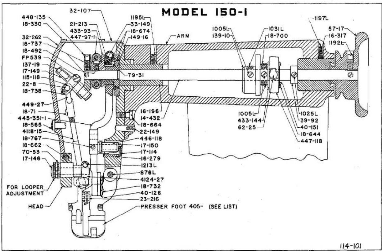
MODEL 150-I 448-135 18-330 32-262 18-737 18-492 FP 539 137-19 17-149 115-118 22-8 18-738 449-27 18-71 445-351-1 18-565 4118-15 18-767 18-662 70-53 17-146 FOR LOOPER ADJUSTMENT HEAD 32-107 21-213 433-93 447-97-1 1195L- 33-149 18-674 149-16 79-31 ARM 1005L- 139-10 1031L- 18-700 1005L- 433-144- 62-25 1025L- 39-92 40-151 18-644 447-118 57-17 16-317 1192L PRESSER FOOT 405- (SEE LIST) 114-101PLATE 2
natural_image
Pure white background with faint circular shapes and no text or symbols
text_image
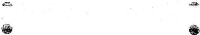
MODEL 150-I 468-23-1 426-47 1160L 41-42 1081L LS 75 16-194 40-60 79-28 447-97-1 1243L 48-105 18-391 18-766 20-60 468-23 1132 L 1333 L 16-148 LS 314 50-160 16-39 14-14 17-150 446-118 HEAD 18-702 CS 327 41-1 SB-15 439-7 18-70 4118-24 18-307 810L 30-52 1170L 36-16 PRESSER FOOT 405-(SEE LIST) 445-35I- 18-767 18-751 1213 L 4124-27 479-8 18-74 17-146 1170 CAPISCREW 114-101PLATE 3

text_image
MODEL ISO-1 RIDGE FORMING DISC 44- (SEE LIST) 24-263 FP 528 5C-210 18-918 FP 539 ARM 16-196 14-432 24-264 22-152 21-75 CYLINDER BASE CS231 107-51 22-271 18-355 18-923 1158L 448-131 1012L 18-664 14-458 1003L 14-395 39-105 14-395 27-166 27-165 1025L 1029L 1031L 18-922 18-924 1005L 433-144 139-10 1220L 1221L 18-38 32-292 125-23 18-700 CS 331 8-89 447-118 16-317 1025L 39-92 1022L 48-127 50-222 1160L BASE OF ARM 18-624 433-151 17-145 114-101PLATE 4
natural_image
Pure geometric shapes (circle and sphere) with no text, numbers, or symbols


MODEL 150-1
text_image
107-51 18-892 149-26 18-924 18-895 110-224 18-921 79-31 76-12 21-300 22-249 RIDGE FORMING DISC REGULATOR CS 231 22-271 21-377 1022L 1003L 18-869 117-41 18-701 448-131 40-148 1158L 18-900 CYLINDER BASE 46-164 18-870 79-9 14-429 1022L 1284L 16-279 48-127 45-352 4124-51 14-429 1022L 1284L 16-279 499-298-1 499-298 20-80 40-144 107-44 A- FP 539 18-872 RIDGE FORMING DISC 44-(SEE LIST) ADJUSTMENT FOR PRESSURE OF RIDGE FORMING DISC 20-120 18-909 865L
text_image
MODEL ISO-1 70-28 18-493 71-87 22508 4129-18 62-25 ARM 433-144 70-52 447-118 48-127 18-870 46-164 14-429 CYLINDER BASE 45-352 433-151 50-222 18-493 70-54 16-239 70-28 71-87 22-256 21-344 14-400 22-255 39-99 18-326 39-117 18-919 17-145 BASE OF ARM 14-395 48-150 114-101PLATE 6

natural_image
Pure graphical elements with no text, numbers, or symbols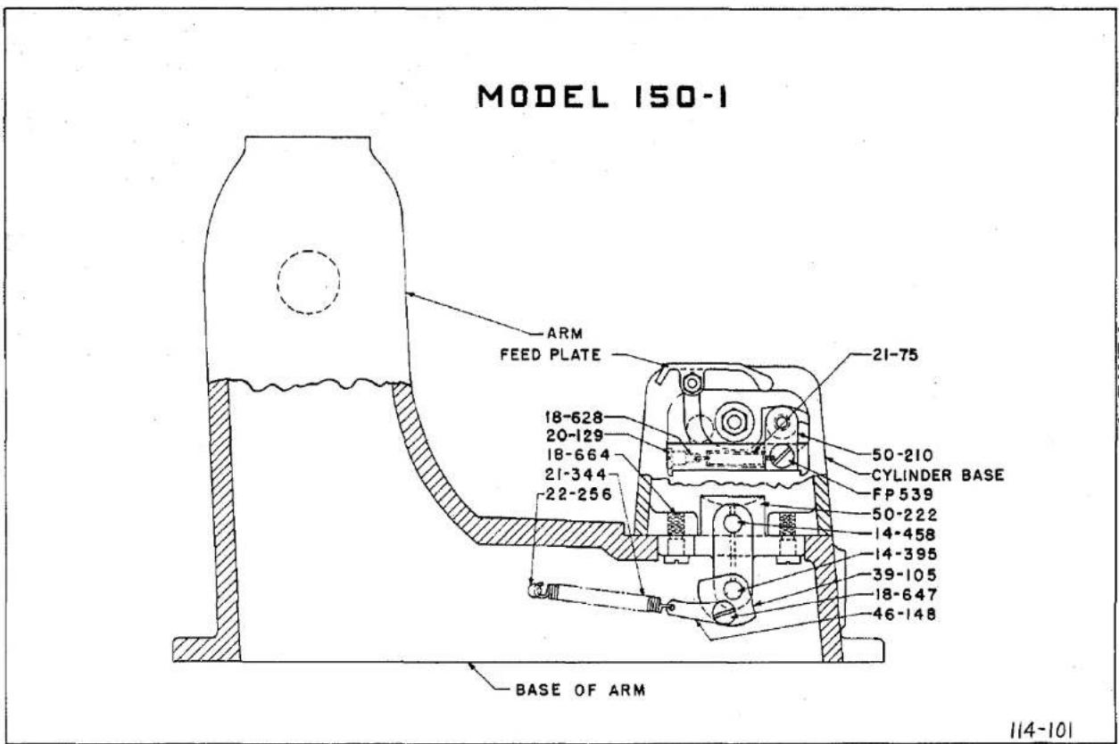
text_image
MODEL 150-1 ARM FEED PLATE 21-75 18-628 20-129 18-664 21-344 22-256 50-210 CYLINDER BASE FP 539 50-222 14-458 14-395 39-105 18-647 46-148 BASE OF ARM 114-101PLATE 7
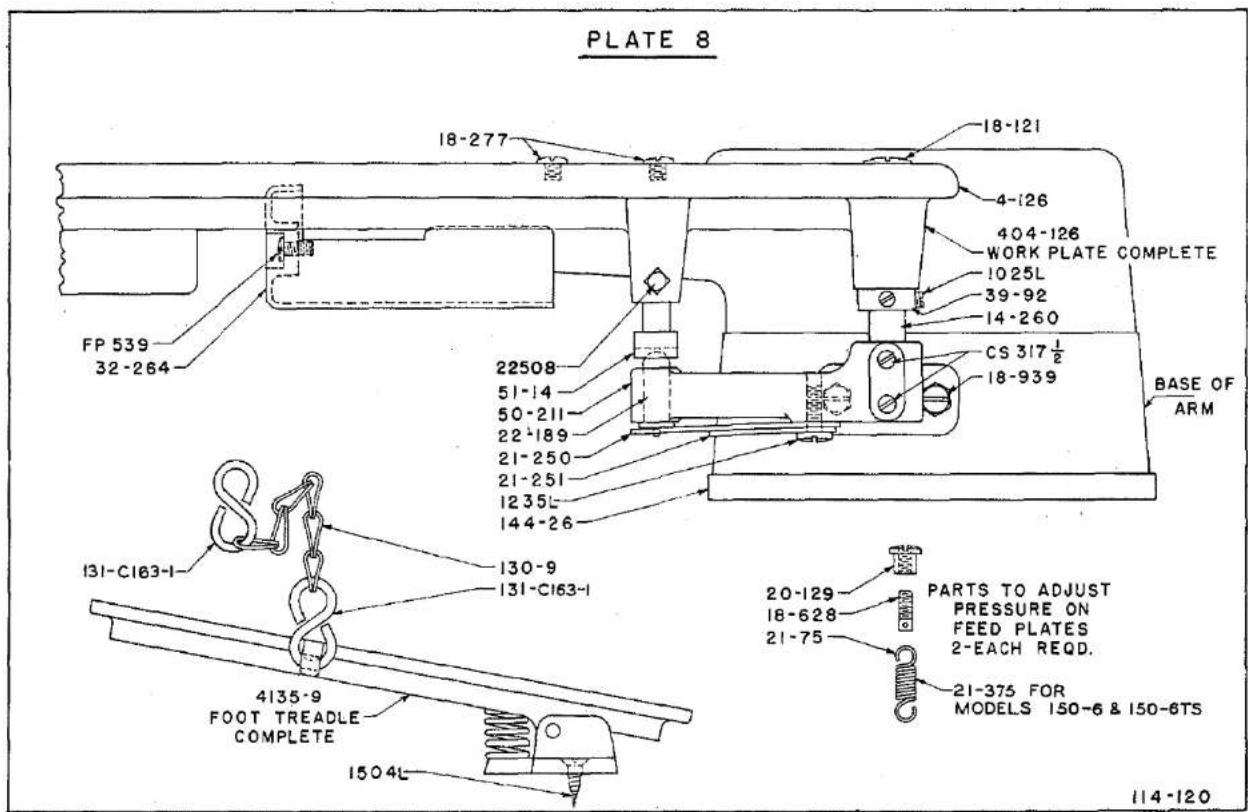
text_image
PLATE 8 18-277 18-121 4-126 404-126 WORK PLATE COMPLETE 1025L 39-92 14-260 CS 317 ½ 18-939 BASE OF ARM FP 539 32-264 22508 51-14 50-211 22-189 21-250 21-251 1235L 144-26 130-9 131-C163-1 4135-9 FOOT TREADLE COMPLETE 20-129 18-628 21-75 PARTS TO ADJUST PRESSURE ON FEED PLATES 2-EACH REQD. 21-375 FOR MODELS 150-6 & 150-6TS 114-120PLATE 8


MODEL ISO-1
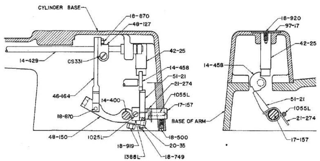
text_image
CYLINDER BASE 18-870 48-127 14-429 CS33I 42-25 14-458 51-21 21-274 1055L 17-157 BASE OF ARM 18-920 97-17 42-25 14-458 51-21 1055L 21-274 17-157 18-870 46-164 14-400 48-150 1025L 18-919 1388L 18-500 20-35 18-749114-101
PARTS LIST FOR LEWIS MODEL 150-1 MACHINES
General Utility Machine for Padding and Felling
| Part No. | Plate | Description |
| 23-216 | 22 | Feed. |
| 24-263 | 22 | Feed Plate (left). |
| 24-264 | 22 | Feed Plate (right). |
| 44-253 | 22 | Standard Ridge Forming Disc for General work - Padding, taping and Felling. |
| 44-277 | 22 | Ridge Forming Disc for tropicals and rayons. |
| 44-278 | 22 | Ridge Forming Disc for hemming knit materials. |
| 44-287 | * | Ridge Forming Disc for extra heavy material. |
| 137-54 | 22 | Cloth Retainer for knit goods in presser foot 405-419, use with Disc 44-278. |
| 137-123 | 22 | Cloth Retainer for tropicals and rayon in Presser Foot 405-508, Use with disc 44-277. |
| 137-132 | 22 | Cloth Retainer in Presser Feet 405-393-2, 405-394-4, 405-395-1 and 405-529. Used with Discs 44-253 and 44-287. |
| 405-393-2 | 22 | Presser Foot for Light Weight Material. |
| 405-394-4 | 22 | Presser Foot for Medium Weight Material. (Standard). |
| 405-395-1 | 22 | Presser Foot for Heavy Material. |
| 405-419 | 22 | Presser Foot for Hemming Knit Material. |
| 405-508 | 22 | Presser Foot for Tropicals and Rayon. |
| 405-529 | 22 | Presser Foot for Extra Heavy Material. |


The Model 150-1 is the basic model for this catalogue. See Plates 2 to 9, for parts, and general list of parts for descriptions, pages 20 to 43.
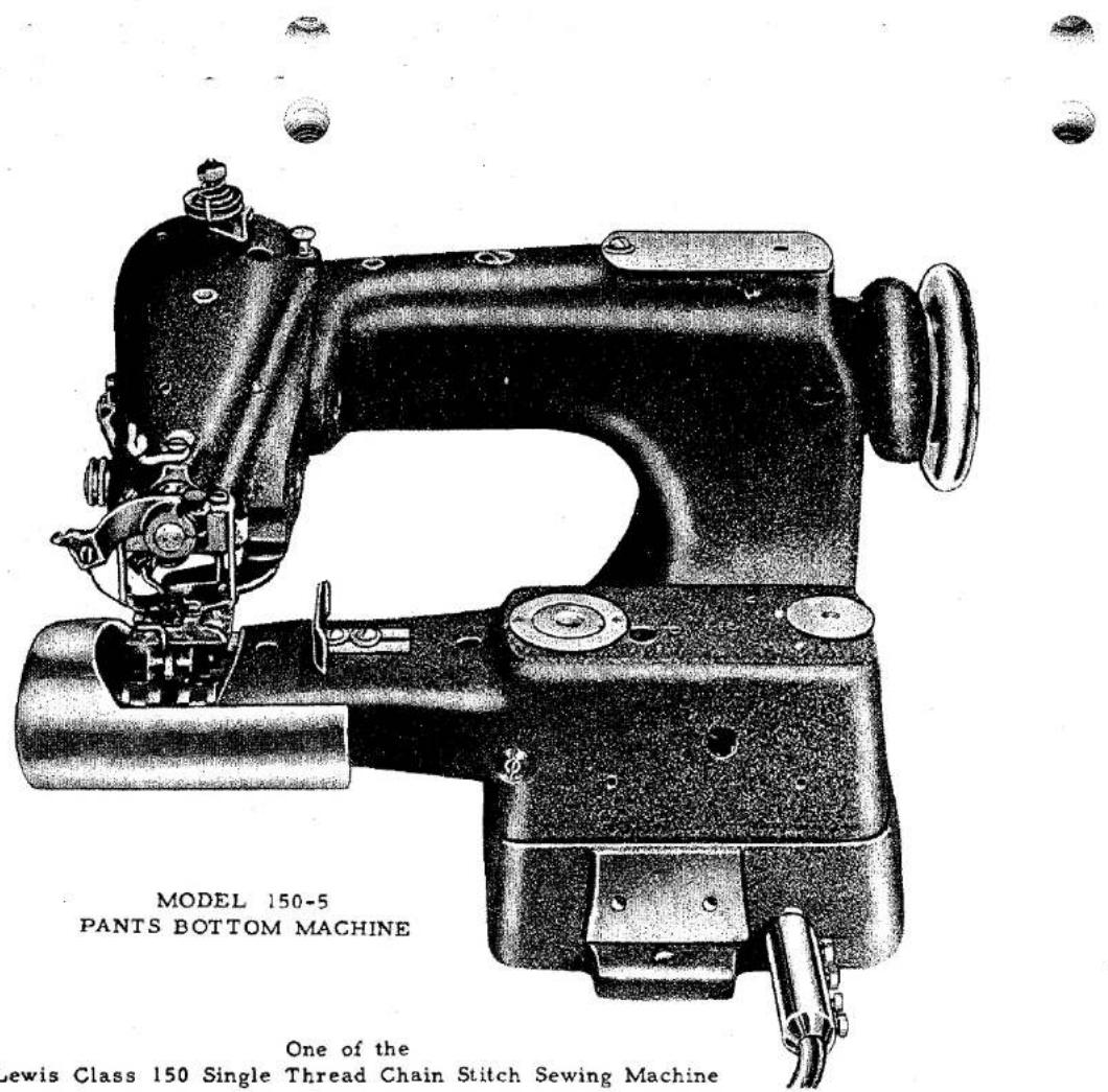
text_image
MODEL 150-5 PANTS BOTTOM MACHINE One of the Lewis Class 150 Single Thread Chain Stitch Sewing MachineMODEL 150-5
The Model 150-5 is specially fitted for sewing the bottom of pants.
The Machine has an adjustable guide that may be set for the desired distance to turn up the bottom, and is equipped with a cylindrical end cover for more easily sewing the pants bottom.
The standard setting of the ridge forming disc is .045" from the left side of the opening in the presser foot.
See General Instructions for Class 150 Machines, for setting up and adjusting.
PARTS FOR MODEL 150-5
For Sewing Pants Bottoms
| Part No. | Plate | Description |
| 18-750 | * | Screw for 75-212 |
| 23-216 | 2, 22, 23, 25 | Feed. |
| 32-264 | 8 | End Cover for Cylinder Base. |
| 44-253 | 22 | Ridge Forming Disc for Heavy Pants Bottoms. |
| 44-296 | 22 | Ridge Forming Disc for pants bottoms. |
| 75-212 | * | Edge Guide for pants bottoms. |
| 137-132 | 22 | Cloth Retainer in Presser Feet 405-395-1, 405-529. Use with Disc 44-253. |
| 137-141 | 22 | Cloth Retainer in Presser Foot 405-394-8. Use with Disc 44-296. |
| 405-394-8 | 22 | Presser Foot for Light and Medium Work. (Std.) |
| 405-395-1 | 22 | Presser Foot for Heavy Work. |
| 405-529 | 22 | Presser Foot for Extra Heavy Work. |


MODEL 150-6 INSTRUCTIONS
The Model 150-6 Machine has been designed to automatically fill in the canvas of collars and lapels to obtain the roll required for the best tailored coats.
The automatic roll in the collar and lapel is produced by filling in a small amount of canvas relative to the body fabric by shaping the work over the ridge forming disc between each row of stitches, therefore, the more rows used, the greater will be the roll.
A reasonably tight tension and stitch must be used and made to hold the small amount of canvas that is filled in, to the cloth between each row of stitches. If a loose stitch is used, there will be no rolled effect to the lapel or collar.
To obtain the best roll for lapels and collars the rows of stitches must be 3/8" of less apart, and a reasonably tight stitch must be used.
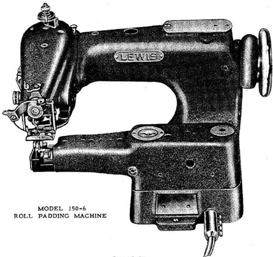
text_image
LEWIS MODEL 150-6 ROLL PADDING MACHINELewis Class 150 Single Thread Chain Stitch Sewing Machine
Lewis Class 150 Single Thread Chain Stitch Sewing Machine


MODEL 150-6

text_image
MODEL 150-8 HEAD 23-216 405-502 18-295 24-270 499-299 CYLINDER BASE 14-435 21-375 44-276 18-750 32-210 14-434 CYLINDER BASE 1132L 114-112PLATE 10
114-112
MODEL 150-6TS INSTRUCTIONS
The Model 150-6TS Machine has been designed to automatically fill in the canvas of collars and lapels to obtain the roll required for the best tailored coats, also to make canvas coat fronts.
The automatic roll in the collar and lapel is produced by filling in a small amount of canvas relative to the body fabric by shaping the work over the Ridge Forming Disc between each row of stitches, therefore, the more rows used, the greater will be the roll.
A reasonably tight tension and stitch must be used and made to hold the small amount of canvas that is filled in, to the cloth between each row of stitches. If a loose stitch is used, there will be no rolled effect to the lapel or collar.
To obtain the best roll for lapels and collars the rows of stitches must be 3/8" or less apart, and a reasonably tight stitch must be used.
Canvas coat fronts requires a through stitch and the Model 150-6TS has been made so that by lifting up on handle lever No. 45-345 (see Plate 11), a supplementary slide in the disc will be moved upwardly and the end of the slide will project above the disc, causing the needle to penetrate through the work.
ADJUSTING DISC
With the ridge forming disc set with the slide in retarded position, and handle lever down, adjust for blind stitching, using ridge forming disc regulator as stated in General Instructions.
The machine can now be changed to through stitching by shifting handle lever No. 45-345, and back to blind stitching without disturbing the setting for the blind stitch operation.
FOR
Roll Padding, Lapels and Collars Also by shifting a handle lever the - machine will sew canvas coat fronts.
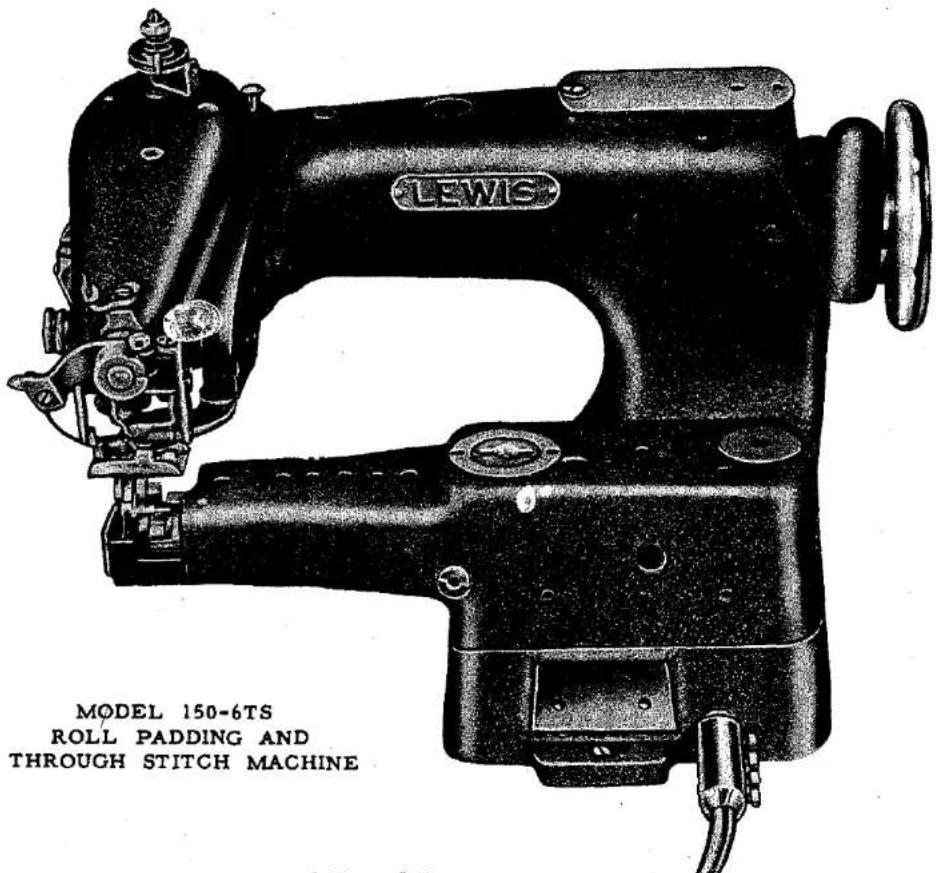
text_image
LEWIS MODEL 150-6TS ROLL PADDING AND THROUGH STITCH MACHINEOne of the Lewis Class 150 Single Thread Chain Stitch Sewing Machine
MODEL 150-6TS
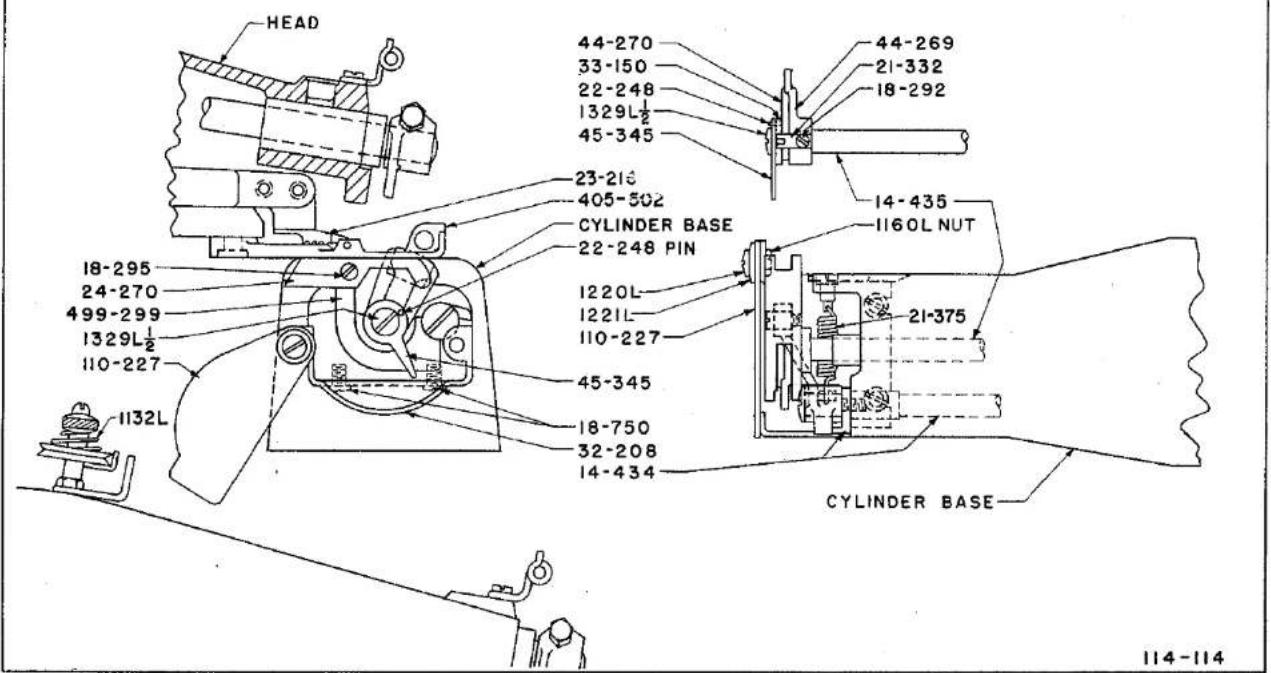
text_image
HEAD 44-270 33-150 22-248 1329L½ 45-345 23-216 405-502 CYLINDER BASE 22-248 PIN 18-295 24-270 499-299 1329L½ 110-227 1132L 45-345 18-750 32-208 14-434 44-269 21-332 18-292 14-435 1160L NUT 21-375 CYLINDER BASE 114-114PLATE 11
PARTS FOR MODEL 150-6TS
Rolled Padding With Through Stitch
For Coat Fronts
| Part No. | Plate | Description |
| 14-434 | 11 | Shaft in Base for Feed Plate Holders |
| 14-435 | 11 | Shaft for Ridge Forming Disc in Cylinder Base |
| 18-292 | 22, 23 | Screw to hold Spring 21-332 on Disc 44-269 |
| 18-295 | 11 | Bearing Screw for Feed Plate in Cylinder Base |
| 18-750 | 11 | Screws for Cover 32-108 in Cylinder Base |
| 21-332 | 11 | Spring on Ridge Forming Disc 44-269 to locate Eccentric 33-150 in Cylinder Base |
| 21-375 | 11 | Spring (heavy) for Feed Plate Holder |
| 22-248 | 11 | Pin in Eccentric 33-150 and Lever handle 45-345 to operate step Ridge Forming Disc |
| 24-270 | 11, 23 | Feed Plate for Roll Padding Models |
| 32-208 | 11 | End Cover for Cylinder Base |
| 33-150 | 11 | Eccentric to adjust supplementary Ridge Forming Disc 44-270 for through stitching |
| 44-269 | 11, 23 | Ridge Forming Disc for through stitch |
| 44-270 | 11, 23 | Supplementary Ridge Forming Disc for through stitch |
| 45-345 | 11 | Handle lever to adjust supplementary Ridge Forming Disc for through stitch |
| 110-227 | 11 | Swing Cover Plate for 32-208 Cover in Cylinder Base |
| 110-230 | 23 | Roll forming plate on bottom of Presser Feet for roll padding |
| 1132 L | 11 | Tension Spring (heavy) for adjusting thread tension' |
| 1160 L | 11 | Nut for Screw 1220 L in Cylinder Base |
| 1220 L | 11 | Screw for Top Cover Plate and for Cover 110-227 in Cylinder Base |
| 1221 L | 11 | Washer for Screw 1220 L in Cover 110-227 in Cylinder Base |
| 1329 L-1/2 | 11 | Screw for end of Shaft 14-435 in Cylinder Base |
Parts not listed are common to Model 150-1. See Plates 2 to 9, Pages 46 to 53.
PARTS FOR MODEL 150-6TS
Rolled Padding With Through Stitch For Coat Fronts

| Part No. | Plate | Description |
| 405-502 | 23 | Presser Foot for Roll Padding, Light, Medium and Heavy Work. Composed of Foot, 6-56, 16-214, 17-87, 18-270, (2) 18-281, 18-292, 18-416, 18-623, 18-643, 21-193, 42-24, 110-230, 122-35, 137-132, (4) 164-9, 1022. |
| 499-299 | 11 | Holder for Feed Plate in Cylinder Base. |
Parts not listed are common to Model 150-1, (See Plates 2 to 9, Pages 46 to 53)
FOR
STAYING FURS
Felling re-enforcing tape along edges.
Felling tapes and padding skins in one operation.
Stitching backs of fur trimmings.
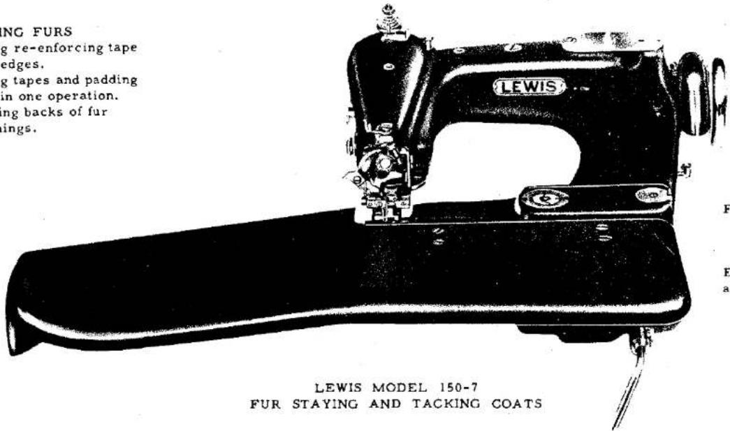
text_image
ING FURS g re-enforcing tape edges. g tapes and padding in one operation. ng backs of fur ings. LEWIS MODEL 150-7 FUR STAYING AND TACKING COATSFOR
Tacking operations on coats.
Equipped with a crown foot.
One of the
Lewis Class 150 Single Thread Chain Stitch Sewing Machine


MODEL 150-7
The Model 150-7 differs from most class 150 machines, by having a yielding ridge forming disc instead of a rigidly mounted disc to form the node for needle penetration.
The machine was designed to sew furs, and the tacking operation on the inside of coats. It will sew across pockets without sewing the pocket shut, or any other operation where the depth of needle penetration must be all the same from the top, such as:
Staying Furs.
Felling reinforcing tape along edges.
Felling tape and padding skins in one operation.
Stitching backs of fur trimmings.
Tacking operations in coats.
With the yielding ridge forming disc it is possible to regulate the depth of the needle penetration from the top side of the work by using an adjustment mounted on the presser foot, known as a crown.
The crown is positioned directly over the yielding ridge forming disc and the machine can be set so that the needle will penetrate the skin of the furs the desired depth, and regardless of the variation in the skin, or the seams, the needle will always penetrate the same distance from the top of the work, because as the top of the work rubs against the crown, the variation of the thickness of the work causes the disc to yield, and the needle will penetrate always the same distance from the top of the garment, at the place where the garment rubs against the crown.
In the tacking operation on coats the machine can be set for blindstitching a single ply of material, and if two, three or four ply of material passes under the crown, the machine will still sew the top single ply only. For instance, tacking near a pocket, the machine will sew across the pocket without sewing the pocket shut.
MODEL 150-7
ADJUSTING YIELDING DISC
With the crown out of contact with the work, and by using the ridge forming disc regulator, as stated in the "General Instructions" for Class 150 machines, set the machine as for blindstitching. After once set all further adjustments should be made by using the Knurled Headed Crown adjusting screw on the presser foot.
To adjust the crown for more penetration of the needle, turn the adjusting screw in anti-clockwise direction. To adjust the crown for less penetration of the needle turn the adjusting screw in clockwise direction.
See General Instructions for Class 150 machine for setting up and other adjustments for Model 150-7 machine.

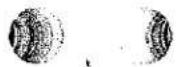
MODEL 150-7
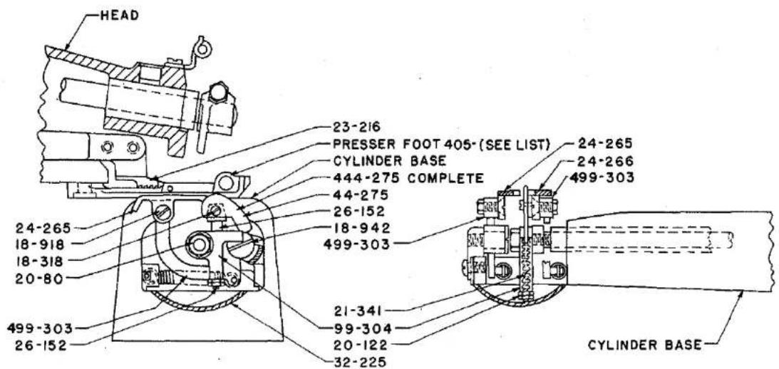
text_image
HEAD 23-216 PRESSER FOOT 405-(SEE LIST) 24-265 CYLINDER BASE 24-266 444-275 COMPLETE 499-303 24-265 18-918 18-318 20-80 18-942 499-303 21-341 99-304 20-122 32-225 499-303 26-152 CYLINDER BASE114-115
PLATE 12
PARTS FOR MODEL 150-7
Fur Staying and Coat Tacking
| Part No. | Plate | Description |
| 4-C114 | 20 | Work Plate, Large. |
| 17-113 | 25 | Stud for Crown 126-36 on Presser Feet 405-409-1 and 405-522. |
| 18-318 | 12 | Screw for attaching Disc 44-275 to Plunger 26-152 in Cylinder Base. |
| 18-744 | 25 | Knurled Screw for adjusting Crowns on Presser Feet. |
| 18-918 | 12 | Taper Bearing Screws for Feed Plates. |
| 18-942 | 12 | Shoulder Bearing Screw for Feed Plate holders 99-303, Models 150-7 and 150-23. |
| 20-80 | 12 | Nut for locking Ridge Forming Disc on Shaft 14-394 in Cylinder Base. |
| 20-122 | 12 | Nut for Plunger 26-152 in Cylinder Base, Models 150-7 and 150-23. |
| 21-243 | 25 | Spring for adjusting screw on Presser Feet with Crown. |
| 21-341 | 12 | Spring for Plunger 26-152 for Ridge Forming Disc 44-275 in Cylinder Base. |
| 21-357 | 25 | Spring (heavy) for Plunger 26-152. |
| 23-216 | 12 | Feed. |
| 24-265 | 12 | Feed Plate (left). |
| 24-266 | 12 | Feed Plate (right). |
| 26-152 | 12 | Plunger for holding Ridge Forming Disc. |
| 32-225 | 12 | Cover for end of Cylinder Base. |
| 44-275 | 12,25 | Ridge Forming Disc (Yielding) for Fur Staying and Bluff Edge. |


PARTS FOR MODEL 150-7
Fur Staying and Coat Tacking


| Part No. | Plate | Description |
| 99-304 | 12 | Holder (yielding) for Ridge Forming Disc Plunger 26-152 in Cylinder Base |
| 122-35 | 25 | Chaining Finger in Presser Foot |
| 126-36 | 25 | Crown on Presser Feet |
| 404-114 | 20 | Large Work Plate Complete for Models 150-7 and 150-23 |
| 405-409-1 | 25 | Presser Foot Complete for Furs Light and Medium, composed of Foot, 6-56, 17-113; 18-292, (2) 18-345, 18-643, 18-744, 21-243, 22-9, 75-153, 122-35, 1733 L, 126-36, 1351 L, LS 330 and CS 335 |
| 405-522 | 25 | Presser Foot Complete for Sewing Heavy Furs, composed of Foot, 6-56, 17-113, 18-292, (2) 18-345, 18-643, 18-744, 21-243, 22-9, 75-153, 122-35, 126-36, 1351 L, LS 330 and CS 335. Use Plunger Spring 21-357 when using this Foot |
| 444-275 | 25 | Ridge Forming Disc (yielding) complete, composed of 18-318, (2) 20-122, 21-341, 26-152, 44-275 and 99-304 |
| 499-303 | 12 | Holder for Feed Plates in Cylinder Base |


Parts not listed are common to Model 150-1. See Plates 2 to 9, Pages 46 to 53.
MODEL 150-9
The Model 150-9 is specially fitted for sewing edges of seams in coats, referred to many times as bookseams, and eliminates the need for piping and matching the thread to piping.
The machine is equipped with a folder for turning the edge under, and is equipped with a work plate.
See General Instructions for Class 150 machines for setting up and adjusting the Model 150-9.
Be sure to specify width of seam desired when ordering this model.
The standard setting of the ridge forming disc is .055" from the left side of the opening in the presser foot when machine is using 1/4" folder, and .065" when using 3/8" folder.

text_image
LEWIS MODEL 150-9 BOOK SEAM MACHINEOne of the Lewis Class 150 Single Thread Chain Stitch Sewing Machine
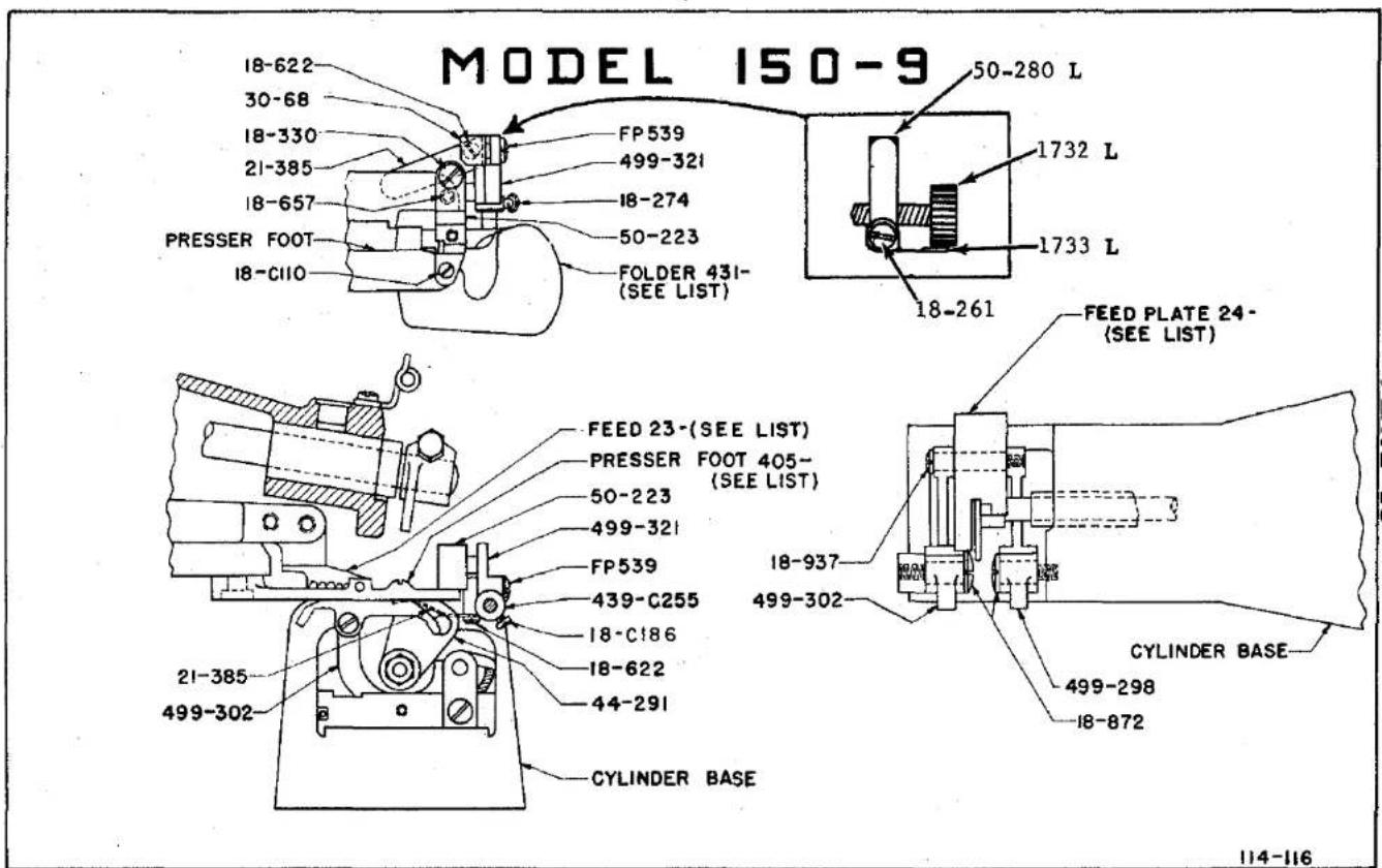
text_image
MODEL 150-9 18-622 30-68 18-330 21-385 18-657 PRESSER FOOT 18-C110 FP 539 499-321 18-274 50-223 FOLDER 431- (SEE LIST) 50-280 L 1732 L 1733 L 18-261 FEED PLATE 24- (SEE LIST) FEED 23-(SEE LIST) PRESSER FOOT 405- (SEE LIST) 50-223 499-321 FP 539 439-C255 18-C186 18-622 44-291 21-385 499-302 CYLINDER BASE 18-937 499-302 CYLINDER BASE 499-298 18-872 114-116PLATE 13

natural_image
Pure electrical circuit lines without any symbolsPARTS FOR MODEL 150-9
Sewing Turned Under Flat Seams
(Book Seam)
| Part No. | Plate | Description |
| 18-C110 | 13, 14 | Screw for attaching Folder Bracket 50-223 to presser feet, Models 150-9 and 150-15 |
| 18-C186 | 13, 14 | Set Screw for Collar 39-C255 for locating folders, Model 150-9 and 150-15 |
| 18-261 | 13 | Screw for attaching 1733 L to 50-280 L |
| 18-330 | 13, 14 | Screw for bracket 50-223 |
| 18-622 | 13 | Screw for spring 21-385 |
| 18-657 | 13, 14 | Screw for clamping folder holders to foot, Models 150-9 and 150-15 |
| 18-872 | 13 | Shoulder Bearing Screw for feed plate holders |
| 18-937 | 13 | Shoulder Bearing Screw for feed plate |
| 23-310 | 13, 23 | Feed Point, 3/32 pitch, 1/4 inch seam |
| 23-311 | 13, 23 | Feed Point, 3/32 pitch, 3/8 inch seam |
| 24-294 | 13, 23 | Feed Plate, 1/4 inch seam |
| 24-295 | 13, 23 | Feed Plate, 3/8 inch seam |
| 44-291 | 13, 23 | Ridge Forming Disc |
| 50-223 | 13, 14 | Bracket on Presser Foot for folders, Models 150-9 and 150-15 |
| 50-280 L | 13 | Bracket for folder adjusting screw |
| 122-43 | * | Chaining Finger for foot 405-537 |
| 404-127 | 13 | Work Support Assembly, swing type |
| 405-537 | 23 | Presser Foot, complete, for 1/4 inch book seam, composed of 5-537, 6-56, 18-292, 18-643 and 122-43 |
| 405-538 | 23 | Presser Foot, complete, for 3/8 inch book seam, composed of 5-538, 6-56, and 18-643 |
| FP505 | 13, 16 | Screw for Cover 32-229 on bottom of Bracket 50-234, Model 150-9 and 150-16 |
| FP-539 | 13 | Screw for clamping folder |
| 431-L175 3/16 | 23 | Folder for 3/16 inch light materials |
| 431-M175 3/16 | 23 | Folder for 3/16 inch medium materials |
| 431-175 3/16 H | 23 | Folder for 3/16 inch heavy materials |
| 431-L175 1/4 | 23 | Folder for 1/4 inch light materials |
| 431-M175 1/4 | 23 | Folder for 1/4 inch medium materials |
| 431-H175 1/4 | 23 | Folder for 1/4 inch heavy materials |
| 1732 L | 13 | Knurled adjusting screw |
| 1733 L | 13 | Retaining Spring for 1732 L |
Parts not listed are common to Model 150-1. See Plates 2 to 9, Pages 46 to 53.
PARTS FOR MODEL 150-9
Sewing Turned Under Flat Seams
(Book Seam)
| Part No. | Plate | Description |
| 431-175 5/16L | 23 | Folder for 5/16" light materials. |
| 431-175 5/16M | 23 | Folder for 5/16" medium materials. |
| 431-175 5/16H | 23 | Folder for 5/16" heavy materials. |
| 431-L175 3/8 | 23 | Folder for 3/8" light materials. |
| 431-M175 3/8 | 23 | Folder for 3/8" medium materials. |
| 431-H175 3/8 | 23 | Folder for 3/8" heavy materials. |
| Use holder 499-323 with this Folder. | ||
| 439-C255 | 13 | Collar on Shank of Folder to locate folder in Presser Foot. |
| 499-321 | 13 | Holder complete for Folders 431-175 (except 431-175-3/8 H - See 499-323) |
| 499-323 | * | Holder complete for Folder 431-175 3/8 H only. |
| 499-298 | 13 | Holder for Feed Plate (right hand). |
| 499-302 | 13 | Holder for Feed Plate (left hand). |
| 41355 U | * | Spacer for 18-937 |


MODEL 150-15
The Model 150-15 is fitted for producing a rolled edge (some time called hand rolled) on:
Scarfs Evening Gowns Dresses Slips Lingerie House Coats Play Suits Novelties
The machine is equipped with a swing work plate so that cylindrical as well as flat work can be rolled edged. The machine is equipped with one folder.
Unless instructed otherwise the machine will be shipped with folder 431-149 which produces a 1/8" rolled edge on medium weight material, such as used in making slips, and if the weight of material is lighter or heavier the width of the hem may vary some what.
We have available at extra charge folders 431-147 for rolled edging such as the flimsy material used in making scarves, and sizes up to the large folders, 431-159 for the extra heavy work.
See General Instructions for class 150 machines, for setting up and adjusting the Model 150-15 machines.
The standard setting of the ridge forming disc is .093" from the right side of the opening in the presser foot.

text_image
LEWIS LEWIS MODEL 150-15 ROLLED EDGE HEMMING MACHINE One of theOne of the Lewis Class 150 Single Thread Chain Stitch Sewing Machine

natural_image
Pure geometric lines and shapes without any text, numbers, or symbolsMODEL 150-15

text_image
HEAD FEED 23-225 PRESSER FOOT 405-497 50-223 499-297 18-937 FOLDER 431- (SEE LIST) 24-272 40-154 CYLINDER BASE 44-272 24-272 18-937 499-302 PRESSER FOOT OR 21-C269 50-223 18-C110 18-C911 FOLDER 439-C255 499-302 499-298 CYLINDER BASE 30-C258 18-657 18-330 499-297 18-C186 114-117PLATE 14
PARTS FOR MODEL 150-15
For Rolled Edge
| Part No. | Plate | Description |
| 18-C110 | 13, 14 | Screw for attaching Folder Bracket 50-223 to Presser Feet |
| 18-C186 | 14 | Set Screw for Collar 439-C255 |
| 18-330 | 2, 13, 14 | Screw for Bracket 50-223 |
| 18-567 | 13, 14 | Screw for clamping folders to foot, Models 150-9 and 150-15 |
| 18-C911 | 14 | Screw on hemmer bracket for cloth retainer spring |
| 18-937 | 14 | Shoulder Bearing Screw for Feed Plate |
| 21-C269 | 14 | Hemmer Spring on Presser Foot 405-497 when using Folders 431-149, 431-150, 431-159 |
| 21-C269-1 | 14 | Hemmer Spring for Folders 431-147, 431-148 |
| 23-225 | 14, 23 | Feed 1/16 Pitch |
| 24-272 | 23 | Feed Plate for Roll Edge |
| 30-C258 | 14 | Clamp for hemmer spring on Presser Foot |
| 40-154 | 14 | Washer between Feed Plate 24-272 and Holder 99-298 in Cylinder Base |
| 44-272 | 14, 23 | Ridge Forming Disc for rolled Hem |
| 50-223 | 14 | Bracket on Presser Foot for Folders, Models 150-9 and 150-15 |
| 122-37 | * | Chaining Finger |
| 405-497 | 23 | Presser Foot for Rolled Hem |
| 431-147 | 23 | Folder for extra light work, use Spring 21-C269-1 |
| 431-148 | 23 | Folder for light work, use Spring 21-C269-1 |
| 431-149 | 23 | Folder for medium work, use Spring 21-C269 |
| 431-150 | 23 | Folder for heavy work, use Spring 21-C269 |
| 431-159 | 23 | Folder for extra heavy work, use Spring 21-C269 |
| 439-C255 | 14 | Collar on shank of Folder to locate folder in presser foot |
| 499-297 | 14 | Holder complete with shaft for folders |
| 499-298 | 14 | Holder for Feed Plate (right hand) in Cylinder Base |
| 499-302 | 14 | Holder for Feed Plate (left hand) in Cylinder Base |


Parts not listed are common to Model 150-1. See Plates 2 to 9, Pages 46 to 53.
MODEL 150-16, 150-20
The Model 150-16 has been developed to make 5/16" or 3/8" wide blind stitched belt loops, and is equipped with trimming knives for cutting the material to the correct width to pass through the folders.
Model 150-20 is quite similar to Model 150-16 except that the folder produces a double inturned edge finish whereas on the Model 150-16, the folder produces an overcast raw edge finish.
When using either model on thin or hard to handle material, a buckram filler is recommended. Part 499-319 may be used to hold the reel of buckram for automatic feeding thru the folder.
See Instructions in this section of catalogue for operating machine, and for parts and folders required for each size belt loop.
See General Instructions for Class 150 machines not found in the instructions for Model 150-16 machine.
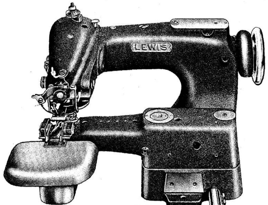
natural_image
Vintage sewing machine with LEWIS label, shown from top and side (no other text or symbols)LEWIS MODEL 150-16
BELT LOOP MACHINE
One of the
Lewis Class 150 Sing
Thread Ch
ain Stitch
Sewing
1.2.2024


MODEL 150-16,150-20
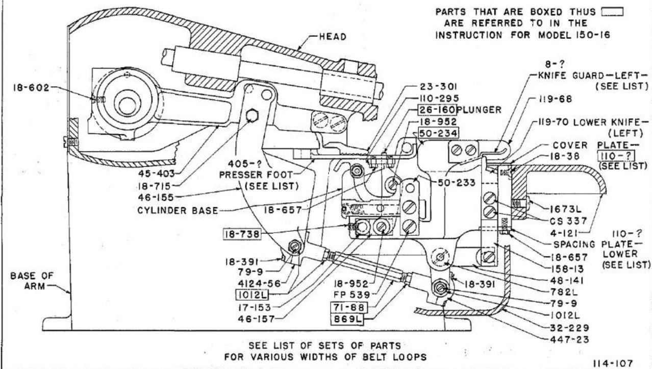
text_image
PARTS THAT ARE BOXED THUS ARE REFERRED TO IN THE INSTRUCTION FOR MODEL 150-16 18-602 HEAD 23-301 110-295 26-160 PLUNGER 18-952 50-234 8-? KNIFE GUARD—LEFT— (SEE LIST) 119-68 119-70 LOWER KNIFE— (LEFT) COVER PLATE— 18-38 110-? (SEE LIST) 405-? PRESSER FOOT (SEE LIST) 18-657 CYLINDER BASE 18-738 1673L CS 337 4-121 IIO-? SPACING PLATE— LOWER (SEE LIST) 18-657 158-13 48-141 782L 79-9 1012L 32-229 447-23 BASE OF ARM 18-391 79-9 4124-56 1012L 17-153 46-157 18-952 FP 539 71-88 869L 18-391 SEE LIST OF SETS OF PARTS FOR VARIOUS WIDTHS OF BELT LOOPS 114-107PLATE 15
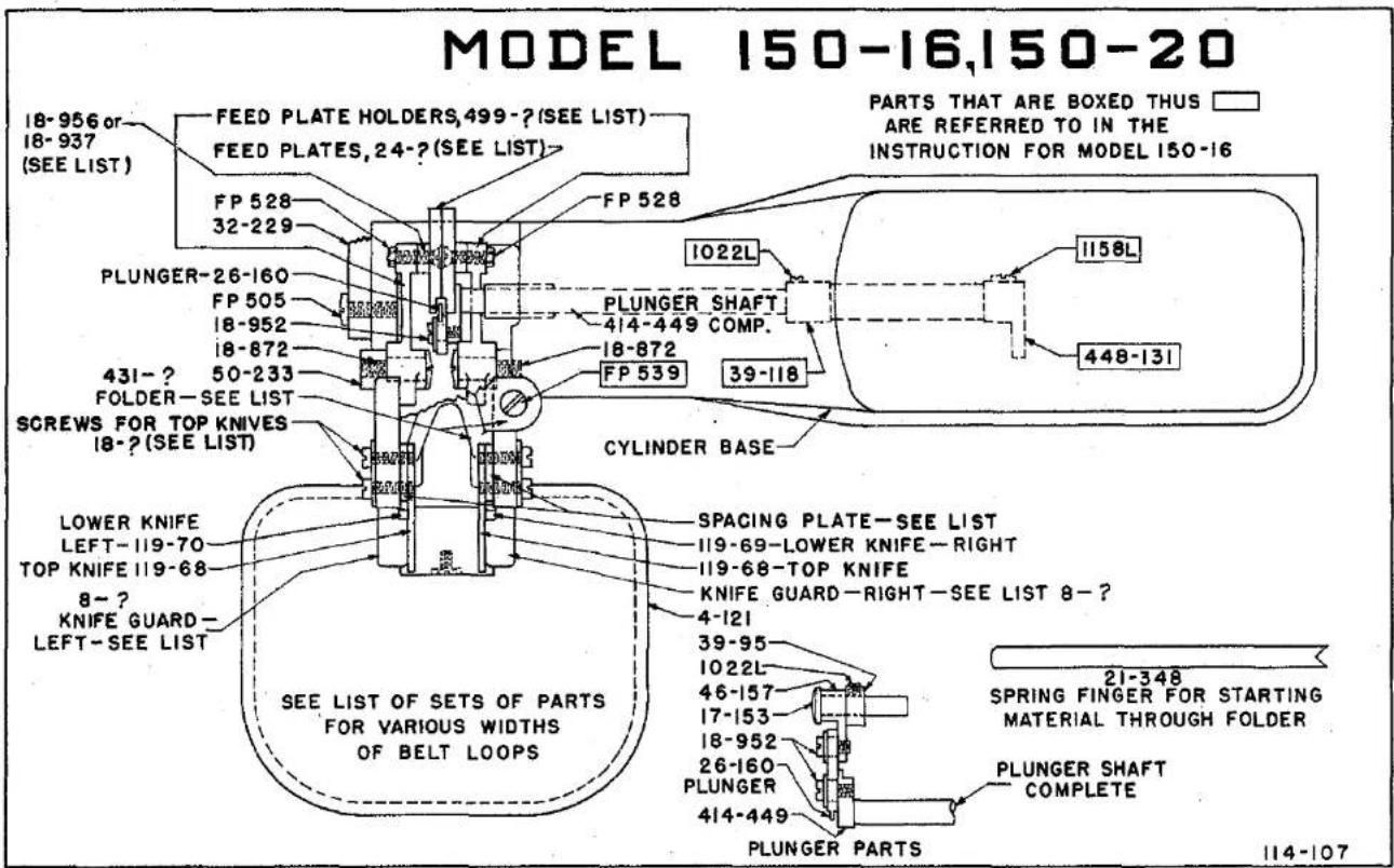
text_image
MODEL 150-16,150-20 PARTS THAT ARE BOXED THUS ARE REFERRED TO IN THE INSTRUCTION FOR MODEL 150-16 18-956 or 18-937 (SEE LIST) FEED PLATE HOLDERS,499-? (SEE LIST) FEED PLATES,24-? (SEE LIST)> FP 528 32-229 FP 528 1022L 1158L PLUNGER-26-160 FP 505 18-952 18-872 431-? 50-233 FOLDER-SEE LIST 431-? FOLDER-SEE LIST SCREWS FOR TOP KNIVES 18-? (SEE LIST) PLUNGER SHAFT 414-449 COMP. 18-872 FP 539 39-118 CYLINDER BASE SPACING PLATE-SEE LIST 119-69-Lower KNIFE-RIGHT 119-68-TOP KNIFE KNIFE GUARD-RIGHT-SEE LIST 8-? 4-121 LOWER KNIFE LEFT-119-70 TOP KNIFE 119-68 8-? KNIFE GUARD- LEFT-SEE LIST SEE LIST OF SETS OF PARTS FOR VARIOUS WIDTHS OF BELT LOOPS 21-348 SPRING FINGER FOR STARTING MATERIAL THROUGH FOLDER PLUNGER SHAFT COMPLETE PLUNGER PARTS PLUNGER PARTS 114-107PLATE 16


MODEL 150-16,150-20

text_image
FELT OIL PAD 63-? -SEE LIST 21-58 COVER PLATE-IIO- (SEE LIST) 50-234 SUPPORT PLATE FOR FELT OIL PAD IIO- (SEE LIST) 22-262 50-233 CS 337- FP 539 SPACING PLATE- LOWER (SEE LIST) 158-13 CS 337 1673L 18-657 158-14 18-307 782L 4124-56 CYLINDER BASE DRIVE PIN,22-? (SEE LIST) 48-141 1012L 40-63 PRESSER FOOT PLUNGER 26-160 50-160 18-307 Y 18-416 18-643 18-270 16-214 17-87 STUD 1022L 21-193 SPRING NEEDLE GUIDE,6-? (SEE LIST) SEE LIST OF SETS OF PARTS FOR VARIOUS WIDTHS OF BELT LOOPSPLATE 17
114-107
PARTS FOR MODEL 150-16, 150-20
For Trimming and Sewing Belt Loops
| Part No. | Plate | Description |
| 4-121 | 15, 16 | Aluminum Work Plate attached to Bracket 50-234 |
| 6-56 | 17, 24 | Needle Guide, Model 150-16 |
| 6-70 | 17 | Needle Guide, Model 150-20 |
| 8-122 | 16, 24 | Guard for right hand top knife, Model 150-16, 3/8"; Model 150-20, 5/16" |
| 8-123 | 16-24 | Guard for left hand top knife, Model 150-16, 3/8"; Model 150-20, 5/16" |
| 8-124 | 24 | Guard for right hand top knife for 5/16" Wide Belt Loop, Model 150-16 |
| 8-125 | 16, 24 | Guard for left hand top knife for 5/16" Wide Belt Loop, Model 150-16 |
| 8-128 | 16 | Guard for right hand top knife, Model 150-20, 3/8" |
| 8-129 | 16 | Guard for left hand top knife, Model 150-20, 3/8" |
| 16-214 | 17, 24 | Bushing in Presser Foot for adjusting cloth retainer |
| 17-87 | 24 | Eccentric Stud in bushing 16-214 for adjusting cloth retainer 137-131 and 137-139 |
| 17-153 | 15, 16, 24 | Stud for Plunger Link 46-157 in Cylinder Base |
| 18-38 | 15 | Screw for attaching Cover Plates, 110-236 and 110-237 to Bracket 50-234 |
| 18-270 | 17 | Screw in end of stud 17-87 in Foot |
| 18-307 | 17 | Screw for attaching Bracket 50-160 to Presser Feet and for holding 22-257 for driving lower knives |
| 18-375 | 16 | Screws for top knives, Model 150-16, 3/8"; Model 150-20, 5/16" |
| 18-391 | 15 | Screws for Ball Joint Cap on 447-23 and 4124-56 |
| 18-400 | 16 | Screws for top knives, Model 150-20, 3/8" |
| 18-416 | 17 | Screw in Bushing 16-214 in Foot |
| 18-602 | 15 | Screw in stitch regulator 149-16 to limit length of stitch |
| 18-643 | 17 | Screw for Needle Guide |
Parts not listed are common to Model 150-1. See Plates 2 to 9, Pages 46 to 53.


PARTS FOR MODEL 150-16, 150-20
For Trimming and Sewing Belt Loops


| Part No. | Plate | Description |
| 18-657 | 15,17 | Screw for attaching Guide Plate 110-295 to bottom of Presser Foot. |
| 18-715 | 15 | Screw for Knife Driving Link 46-155 under Head. |
| 18-738 | 15 | Screw for holding Stud 17-153. |
| 18-872 | 16 | Shoulder Bearing Screw for Feed Plate Holders 99-298 and 99-307 in Cylinder Base. |
| 18-937 | * | Feed Plate Bearing Screw, Model 150-20. |
| 18-951 | 17 | Screw for adjusting pressure of lower knives. |
| 18-952 | 15,16 | Bearing Screws for Plunger 26-160 in Cylinder Base. |
| 18-956 | 16 | Flathead Bearing Screws for Feed Plates. |
| 18-957 | 16 | Screws for Top Knives, Model 150-16, 5/16". |
| 21-58 | 17 | Tension Spring for Lower Knives. |
| 21-193 | 17,24 | Spring for cloth retainer on Presser Foot. |
| 21-348 | 16 | Spring Finger for starting material through folder. |
| 22-257 | 17 | Pin in Crank 48-141 for driving lower knives, Model 150-16. |
| 22-262 | 17 | Spring Pin for Spring 21-58. |
| 22-286 | 17 | Pin in Crank 48-141 for driving lower knives, Model 150-20. |
| 23-301 | 15,24 | Feed. |
| 24-277 | 16 | Feed Plate, Right Hand, Model 150-16. |
| 24-278 | 16 | Feed Plate, Left Hand, Model 150-16. |
| 24-300 | * | Feed Plate, Model 150-20. |
| 26-160 | 15,16,17,24 | Plunger for Node in Cylinder Base. |
| 32-229 | 15,16 | Cover for Bottom of Bracket, 50-234. |
| 39-95 | 16 | Collar for Plunger Link Stud 17-153 in Cylinder Base. |
| 39-118 | 16 | Collar on Ridge Forming Disc Shaft. |
| 40-63 | 17 | Fiber slap washer for 4124-56 Ball Joint under Head. |
| 45-403 | 15 | Feed Lever in Head. |
| 46-155 | 15 | Drive Link for knives under Head. |
| 46-157 | 16,15 | Plunger Link. |
| 48-141 | 15,17 | Crank for driving lower knives. |
Parts not listed are common to Model 150-1. See Plates 2 to 9, Pages 46 to 53.
PARTS FOR MODEL 150-16, 150-20
For Trimming and Sewing Belt Loops
| Part No. | Plate | Description |
| 50-233 | 15,16,17 | Bracket on end of Cylinder Base for Feed Plate Holder. |
| 50-234 | 15,17 | Bracket attached to Cylinder Base for Belt Loop Knives. |
| 63-29 | 17,24 | Felt Oil Pads, between lower knives, Modle 150-16, 3/8"; Model 150-20, 5/16". |
| 63-30 | 17,24 | Felt Oil Pads between lower knives for 5/16" wide belt loops, Model 150-16. |
| 63-33 | 17 | Felt Oil Pads, between lower knives, Model 150-20, 3/8". |
| 71-88 | 15 | Connecting Rod only under Head for operating knives. |
| 79-9 | 15 | Ball Stud in Ball Joints 447-23 and 4124-56. |
| 110-234 | 17,24 | Spacing Plate for Lower Knives for Model 150-16, 3/8"; Modle 150-20, 5/16". |
| 110-236 | 17,24 | Cover plate for Bracket 50-234 for Model' 150-16, 3/8"; Model 150-20, 5/16". |
| 110-237 | 17,24 | Cover Plate for Bracket 50-234 for 5/16" wide belt loops, Model 150-16. |
| 110-238 | 17,24 | Spacing Plate for lower knives for 5/16" wide belt loops, Model 150-16. |
| 110-285 | 16,24 | Spacing Plate or Shim for top knives for Model 150-16, 3/8"; Model 150-20, 5/16". |
| 110-286 | 16,24 | Spacing Plate or Shim for top knives for 5/16" wide belt loops, Model 150-16. |
| 110-293 | 17,24 | Supporting Plate for Felt Oil Pads, Model 150-16, 3/8"; Model 150-20, 5/16". |
| 110-294 | 17,24 | Supporting Plate for felt oil pads between lower knives 5/16" wide belt loops, Model 150-16. |
| 110-295 | 15 | Plates for guiding belt loops on bottom of Presser Foot. |
| 110-310 | 17 | Spacing Plate for lower knives, Model 150-20, 3/8". |
| 110-311 | 17 | Cover Plate for bracket 50-234, Model 150-20, 3/8". |
| 110-312 | 17 | Supporting Plate for felt oil pads between lower knives 3/8" wide belt loops, Model 150-20. |
Parts not listed are common to Model 150-1. See Plates 2 to 9, Pages 46 to 53.


PARTS FOR MODEL 150-16, 150-20
For Trimming and Sewing Belt Loops
| Part No. | Plate | Description |
| 110-314 | 16 | Spacing Plate or Shim for top knives for 3/8" wide belt loops, Model 150-20 |
| 119-68 | 15, 16, 24 | Top knives for Belt Loop Machine Model 150-16 |
| 119-69 | 16, 24 | Bottom knives, right hand side for Belt Loop Machine, Model 150-16 |
| 119-70 | 15, 16, 24 | Bottom knife, left hand side for Belt Loop Machine, Model 150-16 |
| 137-131 | 24 | Cloth retainer for Medium and Heavy work on Presser Foot 405-518 |
| 137-139 | 24 | Cloth retainer for Light and Medium work on Presser Foot 405-517 |
| 158-13 | 15, 17 | Slide Plate for lower knife, left hand side |
| 158-14 | 17 | Slide Plate for lower knife, right hand side |
| CS 337 | 15, 17 | Screws for lower knives |
| FP 505 | 16 | Screw for Cover 32-229 |
| FP 528 | 16 | Nuts for flat head bearing screws 18-956 for Feed Plates |
| FP 539 | 15, 16, 17 | Screw for Bracket 50-233 on end of Cylinder Base, and to attach folder to Bracket 50-234 |
| 782 L | 15, 17 | Screw for Crank 48-141 for driving lower knife |
| 869 L | 15 | Nut (left hand thread) for Ball Joint Connecting Rod under head |
| 1012 L | 15, 17 | Nut for Ball Screw 79-9 in Cylinder Base |
| 1022 L | 16, 17 | Screw for Collar 39-95, and in Presser Foot |
| 1158 L | 16 | Clamp Screw for Crank 448-131 |
| 1673 L | 15, 17 | Screws for holding bracket 50-234 to Cylinder Base, and to hold work plate 4-121 to 50-234 |
| 405-517 | 24 | Presser Foot complete for light and medium material composed of Foot, 6-56, 16-214, 17-87, 18-270, 18-416, 18-643, (4) 18-657, 21-193, (2) 110-295, 137-139 and 1022 L, Model 150-16 |
Parts not listed are common to Model 150-1. See Plates 2 to 9, Pages 46 to 53.
PARTS FOR MODEL 150-16, 150-20
For Trimming and Sewing Belt Loops
| Part No. | Plate | Description |
| 405-518 | 24 | Presser Foot complete for medium and heavy materials composed of Foot, 6-56, 16-214, 17-87, 18-270, 18-416, 18-643, (4) 18-657, 21-193, (2) 110-295, 137-131 and 1022 L, Model 150-16 |
| 405-560 | * | Presser Foot complete composed of Foot, 6-70, 18-643, Model 150-20 |
| 414-449 | 16 | Plunger Shaft complete in Cylinder Base |
| 431-169 | 16, 24 | Folder for 5/16" wide belt loop, light to medium material |
| 431-170 | 16, 24 | Folder for 5/16" wide belt loop, medium to heavy material |
| 431-171 | 16, 24 | Folder for 3/8" wide belt loop, light to medium material |
| 431-172 | 16, 24 | Folder for 3/8" wide belt loop, medium to heavy material |
| 431-M180-3/8 | 16 | Folder for 3/8" wide belt loop, Model 150-20 |
| 431-M180-5/16 | 16 | Folder for 5/16" wide belt loop, Model 150-20 |
| 447-23 | 15 | Ball joint complete under Cylinder Base |
| 448-131 | 16 | Crank with Screw 1158 L, on Ridge Forming Disc Shaft |
| 499-298 | 16 | Holder for Feed Plate, complete with Pin, right side, Model 150-16 |
| 499-302 | * | Holder for feed Plate, complete with Pin, Model 150-20 |
| 499-307 | 16 | Holder for Feed Plate, complete with Pin, left side, Model 150-16 |
| 499-319 | * | Buckram Reel and Holder complete |
| 4124-56 | 15, 17 | Ball joint complete connecting Link 46-155 to Connecting Rod 71-88 |
Parts not listed are common to Model 150-1. See Plates 2 to 9, Pages 46 to 53.


INSTRUCTIONS FOR ADJUSTING AND TIMING LEWIS BELT LOOP MACHINE
See General Instructions for Class 150 for further information.
Models 150-16 and 150-20 can be fitted to sew a 5/16" wide belt loop or a 3/8" belt loop. The Standard machine is fitted for the 5/16" wide belt loop, and the 3/8" belt loop fittings must be specified when ordering.
Parts for 5/16" and 3/8" wide belt loops are listed on pages 93 and 94.
- Adjusting and Timing Plunger:
Adjust plunger 26-160 to cloth opening in Presser Foot.
Loosen Screw 1158 L in crank 448-131 and screw 1022 L in collar 39-118, also screw 18-738 in Bracket 50-234 and set plunger so there is 3/64" between left side of cloth opening in presser foot and left side of plunger, at "X" as shown on plate No. 17, For Model 150-16. On Model 150-20, the measurement at "X" is 5/32" when using 5/16" folder and 11/64" when using 3/8" folder.
- Adjust Feed:
Set feed on stitches per inch required, not less than 6 stitches per inch. The stitch is regulated by the knob 426-47, plate 3 located on top of the arm of the machine, near the head. First, open the top cover of the machine to observe the feed indicator on the shaft, with numerals which indicate on the number of stitches per inch, press down the feed knob located on top of the machine which will engage a slot in the feed mechanism; now turn the hand wheel over and away from you, while holding the knob in the slot, to lengthen stitch, and toward you to shorten stitch, and observe through the opening in the top of the arm, the number on the feed disc as you turn until the numeral, indicating the stitches per inch, is directly under the indicator.
MODEL 150-16, 150-20
INSTRUCTIONS FOR ADJUSTING AND TIMING LEWIS BELT LOOP MACHINES
Rotate handwheel clockwise until needle point is even with right side of cloth opening in presser foot as needle travel is from right to left. Loosen two feed point screws 18-732 and set feed so teeth contact feed plattens and front end of feed point is 1/16" to rear of needle, tighten 18-732 screws.
3. Adjust Cloth Retainer:
Set front end of retainer in center of cloth opening in presser foot and turn 16-214 bushing clockwise until end of spring 21-193 is on top, tighten 1022 L screw to hold bushing in place. Turn eccentric stud 17-87 until there is 1/32" between front end of retainer, and side of needle as shown at "Y" on Plate 17. For heavy materials, set front end of retainer 1/16" from side of needle. Tighten 1022 L and 18-416 screws.
4. Adjust Top Knives:
Loosen four knife holding screws and set lower edge of knives 1/8" above top of lower knife cover plate. Tighten screws.
5. Adjust Lower Knives:
Turn handwheel clockwise until lower knives are at top of stroke. Loosen nuts 869 L and 1012 L on ball joint connecting rod 71-88 and turn connecting rod until front edge of lower knife is 1/32" above bottom edge of top knife. Tighten 869 L and 1012 L nuts.
6. Adjust Folder:
Loosen screw FP 539 and adjust folder sideways until stitch is set at edge of top fold of belt loop. Tighten screw.


MODEL 150-16
PARTS FOR 5/16" AND 3/8" BELT LOOPS
STANDARD
Light to Med. Material Med. to Heavy Material
| 5/16" Loops | 3/8" Loops | 5/16" Loops | 3/8" Loops | Description |
| 405-517 | 405-517 | Light to Medium Presser Foot complete. | ||
| 405-518 | 405-518 | Medium to Heavy Presser Foot complete. | ||
| 8-124 | 8-124 | Guard for right top knife, 5/16" loops. | ||
| 8-122 | 8-122 | Guard for right top knife, 3/8" loops. | ||
| 8-125 | 8-125 | Guard for left top knife, 5/16" loops. | ||
| 8-123 | 8-123 | Guard for left top knife, 3/8" loops. | ||
| 63-30 | 63-30 | Oil Pad for 5/16" loop under cover 110-238. | ||
| 63-29 | 63-29 | Oil Pad for 3/8" loops under cover 110-236. | ||
| 110-237 | 110-237 | Cover Plate for Bracket 50-234, 5/16" loops. | ||
| 110-234 | 110-234 | Spacing Plate for lower knives, 3/8" loops. | ||
| 110-238 | 110-238 | Spacing Plate for lower knives, 5/16" loops. | ||
| 110-236 | 110-236 | Cover Plate for Bracket 50-234, 3/8" loops. | ||
| 110-286(2) | 110-286(2) | Spacing Plate for top knives, 5/16" loops. | ||
| 110-285(2) | 110-285(2) | Spacing Plate for top knives, 3/8" loops. | ||
| 110-294 | 110-294 | Supporting Plate for Oil Pad, 5/16" loops. | ||
| 110-293 | 110-293 | Supporting Plate for Oil Pad, 3/8" loops. | ||
| 431-169 | Folder for 5/16" loops, light to med. Mat'l. | |||
| 431-171 | Folder for 3/8" loops, light to med. Material. | |||
| 431-170 | Folder for 5/16" loops, Med. to Heavy Mat'l. | |||
| 431-172 | Folder for 3/8" loops, Med. to Heavy Mat'l. |
MODEL 150-20
PARTS FOR 5/16" AND 3/8" BELT LOOPS
| 5/16" Loops | 3/8" Loops | Description |
| 405-560 | 405-560 | Presser Foot complete |
| 8-122 | Guard for right top knife | |
| 8-123 | Guard for left top knife | |
| 8-128 | Guard for right top knife | |
| 8-129 | Guard for left top knife | |
| 63-29 | Oil Pad under cover 110-236 | |
| 63-33 | Oil Pad under cover 110-311 | |
| 110-234 | Spacing Plate for lower knives | |
| 110-236 | Cover Plate for bracket 50-234 | |
| 110-285 | Spacing Plates for top knives | |
| 110-293 | Supporting Plate for Oil Pad | |
| 110-310 | Spacing Plate for lower knives | |
| 110-311 | Cover Plate for bracket 50-234 | |
| 110-312 | Supporting plate for Oil Pad | |
| 110-314 | Spacing Plate for top knives | |
| 431-M180-5/16 | Folder | |
| 431-M180-3/8 | Folder |


MODEL 150-17
The Model 150-17 was developed for padding Collars and lapels. In some localities operators have become so proficient that they finish the operation without stopping the machine.
The Model is equipped with a foot, having a retainer with a finger so that at the end of each row of stitches the thread will break across the finger instead of across the looper, leaving enough thread protruding from the needle, so that the thread will not come out of the needle when starting the next row of stitches.
The machine is equipped with a Foot Treadle and does not have a work plate.
Refer to General Instructions for setting up and adjusting.


The Machine is not equipped with work plate.
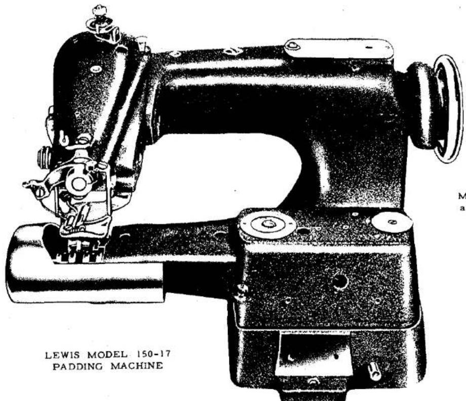
text_image
LEWIS MODEL 150-17 PADDING MACHINEMachine is operated by a foot treadle.
One of the Lewis Class 150 Single Thread Chain Stitch Sewing Machine


PARTS FOR MODEL 150-17
Padding Collars and Lapels. Has Foot with Retainer -- Designed to break the thread without stopping machine.
| Part No. | Plate | Description |
| 6-56 | 23 | Needle Guide. |
| 18-292 | 23 | Screw for Chaining Finger 122-35 on Presser Foot. |
| 18-643 | 23 | Screw for Needle Guide 6-56 on Presser Foot. |
| 21-63 | 23 | Spring for Retainer 4137-126 on Presser Foot. |
| 23-217 | 23 | Feed for Model 150-17. |
| 122-35 | 23 | Chaining Finger on Presser Foot. |
| 130-9 | 8 | Chain for Foot Treadle 4135-9. |
| 131-C163-1 | 8 | Hook for attaching chain to Treadle 4135-9. |
| 405-503 | 23 | Presser Foot complete, for padding Model 150-17. |
| 4135-9 | 8 | Foot Treadle complete with spring, Bracket and Hinge Pin. |
| 4137-126 | 23 | Cloth Retainer for Presser Foot. |
MODEL 150-23
The Model 150-23 machine has been developed to produce a very flexible loose stitch for tacking the facing to the forepart of coats. The operation is sometimes referred to as Bluff Edging.
The machine differs from other Class 150 machines by having a yielding disc made to shog or move from right to left, and the needle penetrates once in the single ply body fabric of the coat when the disc is in the left hand shogging position, feeds once then catches the facing that has been folded over on its self when the disc is in the right hand shogging position, continuing until the operation on the coat has been finished, then facing is turned to it's natural position. The loose tacking blind stitch lies between the facing and the forepart, and will hold the coat in shape.
Fold the facing over on itself, so that the edge of the fold will be the distance selected from the edge of the coat to sew the tacking stitches, press the knee against the knee press which will lower the feed plate, and recede the ridge forming disc, place one end of the coat with the facing folded under the presser foot with edge of the fold against the front edge guide of the presser foot.
-
To adjust for needle penetration in the single ply body fabric, use the more or less dial on top of the base, and turn the hand wheel of the machine in clockwise direction until the ridge forming disc has shogged or moved to the left hand side of the foot opening and is under the cloth retainer. Continue to turn until the point of the needle is ready to enter the work. Turn the regulator dial to the "MORE" for deeper penetration, and to the "LESS" for less penetration of the needle. Adjust until the needle catches only one or two strands of the body fabric.
-
To adjust for sewing the facing, turn the hand wheel of machine in clockwise direction until the ridge forming disc has shogged to the right hand side of the cloth opening, and is under the crown, and with the needle ready to penetrate the folded facing.


To adjust for needle penetration in the folded facing always use the crown and by turning the knurled headed screw in clockwise direction until the end of the crown forces the facing down, so that the needle will catch about two strands of the facing material.
Sew a few stitches, and if depth of penetration is not quite right, turn the adjustments a notch at a time to correct, bearing in mind the "MORE" or "LESS" regulator adjusts the needle penetration on single layer of body fabric on the left hand side and the crown screw adjusts the needle penetration on the folded facing side.
The edge guide fastened to the front end of the presser foot must be set so the folded edge of the facing will be guided to the projection on the under side of the crown without the edge crowding the crown projection.
ADJUSTING MODEL 150-23
(Letter "P" after part numbers refers to plate number.)
The Model 150-23 machine is constructed the same as other models in the Class 150 machines except the ridge forming disc mechanism is made to shog, or move from right to left, and required an added line of parts to shog the disc so that the needle will pass over the disc alternately penetrating the material first on the left side, and while the machine is feeding the disc moves to the right hand side, and the needle penetration takes place, requiring gears to move the disc every other stitch.
The ridge forming disc oscillates on every stroke of the needle, and is operated by eccentric 433-144 (P20 and P21), and is timed by spot screw 18-700, (P21), therefore, is properly timed when assembled.
The shogging mechanism must be timed relative to the oscillating motion of the ridge forming disc which is accomplished by loosening screws 1029 L (P20 and P21) in gear 27-76 (P21), turn the hand wheel in clockwise direction until the nose of the ridge forming disc when receding is even with the bottom of the presser foot, hold hand wheel in this position and turn the gear 27-76 by hand in clockwise direction until the disc just starts to move either to the right or to the left and tighten set screw 1029 L. Turn the machine over by hand and note that the disc starts to shog when on the receding or backward movement, the nose of the disc is even with the bottom of the presser foot.


When properly timed the machine will be feeding when the disc is shogging and the disc will be in its most forward position when the point of the needle is even with the edge of the needle guide ready to penetrate the material.
The periphery of the ridge forming disc is convex, See 444-275 (P25), and the retainer 137-77, and crown 126-43 and (P25) are both concave on the under sides, and the disc must be set so the periphery of the disc accurately matches the concave shape on the under side of the retainer and crown.
The above adjustment is made by loosening the clamp screw in crank 448-171 (P19) and moving the disc 444-275 and disc shaft 14-394 (P19) so that the disc matches the crown and retainer. When making this adjustment also loosen clamp screw for the lower lever, 448-139 (refer to plate 21), as it is necessary to see that the distance at X is 7/32" from side of sleeve 70-55, to the end of cradle 140-12, when the disc is on the right hand shog under the crown. It is also necessary to set the width of the groove (refer to Plate 21) for the bearing Pin, 22-254, use two screw drivers, one through the hole in the top of the base held against the crank 448-171 and one against the side of the sleeve, 70-55, and slide the sleeve so that there will be no shake in bearing pin, 22-254. See that the disc is in place under the crown and distance X is correct. Tighten the screw 1158 in crank 448-171.
Again check to see that the disc matches the concave on the under side of the crown, and distance X is correct, and tighten clamp screw 18-757 in crank, 448-139 securely.
If adjustments have been made correctly there will be no bind in the ball joint 4124-55. Carefully check by turning hand wheel to see that the joint is free in all positions.
Care should be taken when making this adjustment to see that the square headed bearing pin 22-254, that slides in the groove formed by the two parts 70-55 and 448-171 (P21) slides freely in the groove without any play. The groove is adjustable so that a good fit can be maintained to take up wear, as sleeve 70-55 is split and fits into the hole of crank 448-1717 (P21), and is clamped by screw #1158 that also clamps both parts to the disc shaft 14-394, tighten screw securely.
See General Instructions for Class 150 machines for setting up and other adjustments for the Model 150-23 machine.
FOR
(Bluff Edge)
Tacking the facing of womens' coats can tack any distance from edge of the coat.

text_image
edge) the facing of coats can tack ce from edge LEWIS LEWIS MODEL 150-23 (Bluff Edge) FACING MACHINELEWIS MODEL 150-23
(Bluff Edge) FACING MACHINE
One of the
Lewis Class 150 Single Thread Chain Stitch Sewing Machines
MODEL 150-23

text_image
447-125 27-215 ARM 45-357 47-119 18-943 24-265 18-918 499-303 444-275 44-275 18-318 26-152 18-942 CYLINDER BASE BASE OF ARM114-118


MODEL 150-23
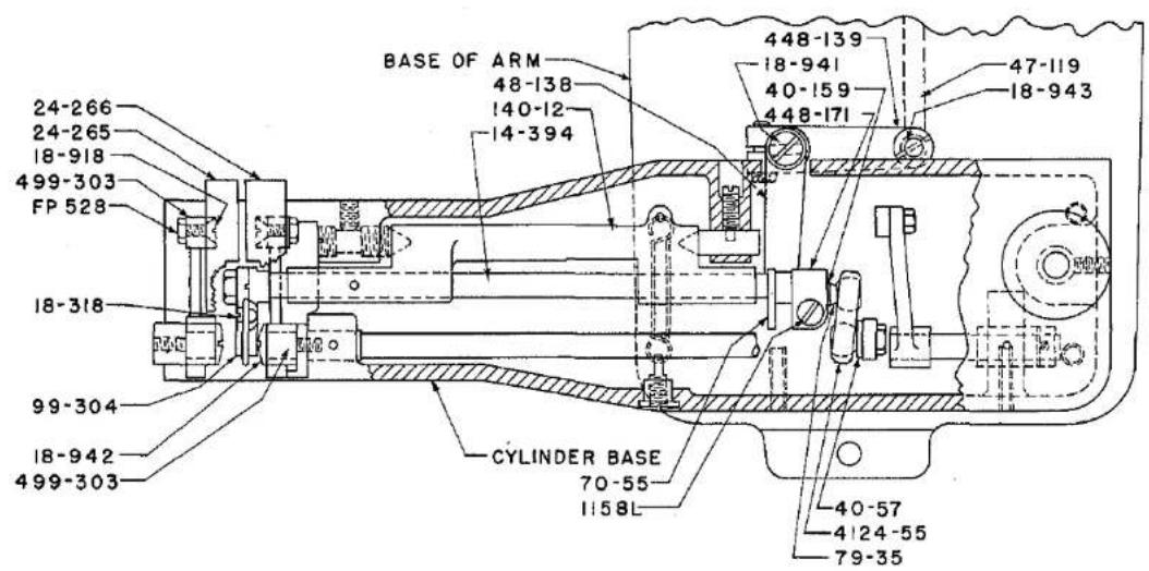
text_image
BASE OF ARM 48-138 140-12 14-394 448-139 18-941 40-159 448-171 47-119 18-943 24-266 24-265 18-918 499-303 FP 528 18-318 99-304 18-942 499-303 CYLINDER BASE 70-55 1158L 40-57 4124-55 79-35PLATE 19
114-118
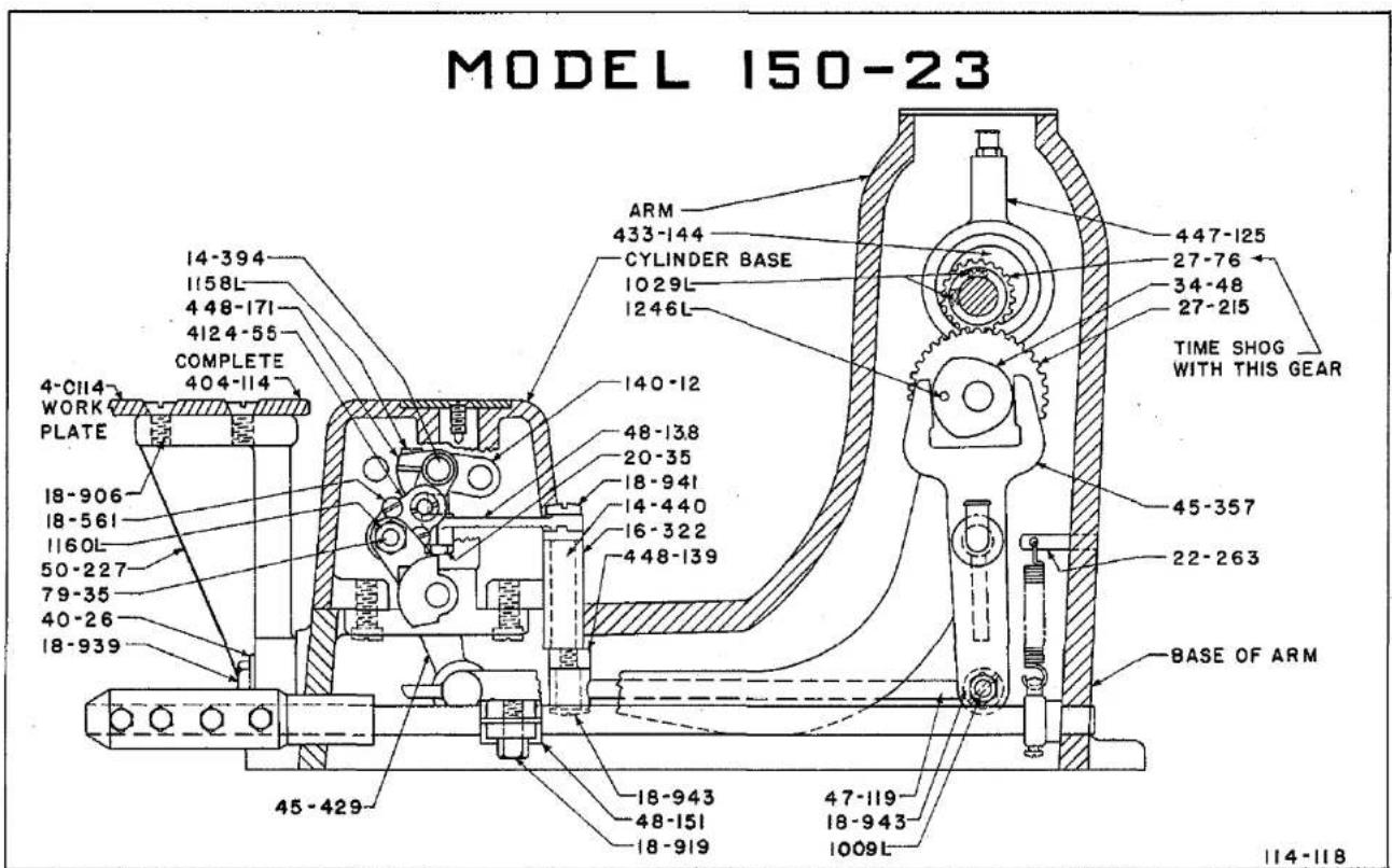
text_image
MODEL 150-23 4-CII4 WORK PLATE 18-906 18-561 1160L 50-227 79-35 40-26 18-939 14-394 1158L 448-171 4124-55 COMPLETE 404-114 ARM 433-144 CYLINDER BASE 1029L 1246L 140-12 48-138 20-35 18-941 14-440 16-322 448-139 ARM 447-125 27-76 34-48 27-215 TIME SHOG WITH THIS GEAR 45-357 22-263 BASE OF ARM 45-429 18-943 48-151 18-919 47-119 18-943 1009L 114-118PLATE 20


natural_image
Pure horizontal lines with circular markers at endpoints (no text or symbols)
text_image
MODEL 150-23 447-125 27-76 1029L 16-329 18-700 433-144 ARM 444-275 COMPLETE 18-318 24-266 44-275 499-303 140-12 14-394 70-55 79-35 4124-55 1158L 448-171 GROOVE X-X CS 317 1022L CS 462 62-21 34-48 16-255 14-441 1197L 27-215 1235L 45-357 BASE OF ARM 99-304 20-122 22-152 21-341 26-152 CYLINDER BASE 22-254- 48-138 20-35 1160L 40-159 16-322 18-757 14-440 448-139 47-119 18-943 114-118PLATE 21
PARTS FOR MODEL 150-23
Tacking Facing to Forepart (Bluff Edge)
| Part No. | Plate | Description |
| 4-C114 | 20 | Work Plate (large) for Models 150-7 and 150-23 |
| 14-394 | 19, 20, 21 | Shaft for Ridge Forming Disc in Cylinder Base |
| 14-440 | 20, 21 | Shaft for Crank 48-138 to Shog Disc, Model 150-23 |
| 14-441 | 21 | Jack Shaft in Arm |
| 16-255 | 21 | Bushing (Eccentric) in Arm for adjusting Gear 27-215 |
| 16-322 | 20, 21 | Bushing in Base for 14-440 for Shogging Disc |
| 16-329 | 21 | Bushing for Main Shaft Hand Wheel end of Arm |
| 18-318 | 18, 19, 21, 25 | Screw for attaching Ridge Forming Disc 44-275 to Plunger 26-152 in Cylinder Base |
| 18-561 | 20 | Screws in 4124-55 Ball Joint in Base |
| 18-700 | 21 | Spot screw for Ridge Forming Disc Eccentric 433-144 |
| 18-757 | 21 | Hex Screw for 448-139 in Base |
| 18-906 | 20 | Flat Head Screws to fasten work plate 4-114 to Bracket |
| 18-918 | 18, 19 | Taper bearing Screws for Feed Plates |
| 18-939 | 20 | Hex Screw for Holding Work Table Bracket 50-227 to Machine |
| 18-941 | 19, 20 | Screw for Crank 48-138 to Shog Disc in Base |
| 18-942 | 18, 19 | Shoulder Bearing Screw for Feed Plate Holder 99-303, Models 150-7, 150-23 |
| 18-943 | 18, 19, 20, 21 | Shoulder Bearing Screws for Connecting Rod 47-119 |
| 20-35 | 20, 21 | Nut for Bearing Pin 22-254 in Cylinder Base |
| 20-122 | 21, 25 | Nut for Plunger 26-152 in Base,Models 150-7, 150-23 |
| 21-243 | 25 | Spring for adjusting screw on Presser Feet with Crown |
Parts not listed are common to Model 150-1. See Plates 2 to 9, Pages 46 to 53.


PARTS FOR MODEL 150-23
Tacking Facing to Forepart (Bluff Edge)

| Part No. | Plate | Description |
| 21-341 | 21, 25 | Spring for Plunger 26-152 for Ridge Forming Disc in Cylinder Base, Models 150-7 and 150-23 |
| 21-357 | 25 | Spring (heavy) for Plunger 26-152 |
| 22-254 | 21 | Bearing Pin for 48-138 in Cylinder Base |
| 22-263 | 20 | Pin for Spring 21-344 in Arm, Model 150-23 |
| 23-217 | 25 | Feed |
| 24-265 | 18, 19, 21, 25 | Feed Plate (left) for Models 150-7 and 150-23 |
| 24-266 | 19, 21, 25 | Feed Plate (right) for Models 150-7 and 150-23 |
| 26-152 | 18, 21, 25 | Plunger for holding Ridge Forming Disc 44-275, Models 150-7, 150-23 |
| 27-76 | 20, 21 | Gear on Main Shaft for driving Gear 427-183 |
| 27-215 | 18, 20, 21 | Gear for Shogging Disc |
| 32-225 | 12 | Cover for end of Cylinder Base |
| 34-48 | 20, 21 | Cam for Shogging Ridge Forming Disc |
| 40-26 | 20 | Washers for Screw 18-804 for attaching Bracket 50-227 to machine |
| 40-57 | 19 | Slap Washer for 4124-55 in Base |
| 40-159 | 19, 21 | Washer for Ball in Crank 448-137 in Cylinder Base |
| 44-275 | 18, 21, 25 | Ridge Forming Disc, yielding, for fur padding and bluff edge, Models 150-7 and 150-23 |
| 45-357 | 18, 20, 21 | Fork Lever for Shogging Ridge Forming Disc in Arm |
| 45-429 | 20 | Lever for oscillating ridge forming disc, in Base of Arm |
| 47-119 | 18, 19, 20, 21 | Connecting Rod for Shogging Ridge Forming Disc in Base of Arm |
| 48-138 | 19, 20, 21 | Crank on Shaft 14-440 for Shogging Disc |
| 48-151 | 20 | Crank on Shaft 14-400 to depress Feed Plates and roll back Ridge Forming Disc |
| 50-227 | 20 | Bracket for Large Work Table 404-114 |
| 62-21 | 21 | Oil Cup for Shaft 14-441 in Arm, Model 150-23 |
Parts not listed are common to Model 150-1. See Plates 2 to 9, Pages 46 to 53.
PLATE 22
MODEL 150-1

405-393-2 LIGHT
405-394-4 MEDIUM
405-395-1 HEAVY
405-419
405-508
24-263
24-264
PARTS COMMON TO ALL FEET
ON THIS PAGE AND TO 405-502

18-270

21-193

17-87

16-214

42-13
42-24

122-35
122-39

6-56

18-643

1351L

1022L

18-416

18-623

18-292

164-9
MODEL 150-5
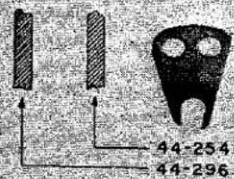
text_image
44-254 44-296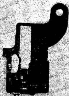
natural_image
Pure mechanical part diagram without any text, numbers, or symbols
137-132
137-134
137-14
405-394-8 LIGHT & MEDIUM
405-395-1 HEAVY
405-529 EXTRA HEAVY
PLATE 23
| MODEL 150-6 | MODEL 150-6TS ONLY | |||
 |  | [8-28] | 110-230 | 44-270 |
| 405-502 | 44-276 | 24-270 | 23-216 | 44-269 |
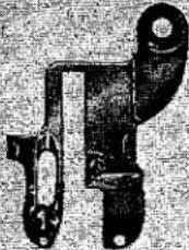 |  |  |  | |
| 405-537 | 44-291 | [5THW] | 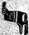 | 431-175 14 LIGHT MEDIUM HEAVY |
| 405-538 | 24-294 | 23-310 | 431-175 38 LIGHT MEDIUM HEAVY | |
 |  |  | [T2D8] | NO. 00 431-1471 431-1482 431-1493 431-1504 431-159 |
| 405-497 | 44-272 | 24-272 | 23-225 | |
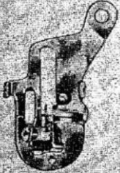 | [7262] |  |  | |
 | 44-253 | [SBY] |  | [BC4W] |
| [3H28] | [HKYY] | [XBT4] | ||
| [222T] | [HCS8] | 18-643 | 24-263 | [HE20] |
PLATE 24
MODEL 150-16
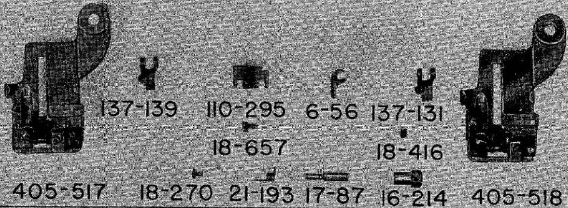
text_image
137-139 110-295 6-56 137-131 18-657 18-416 405-517 18-270 21-193 17-87 16-214 405-5185/16 LOOP PARTS

110-294
63-30 110-238

natural_image
Pure electrical circuit lines without any symbols8-125 8-124

110-286

natural_image
Close-up of a mechanical component with a flanged neck and circular end (no visible text or symbols)431-169
431-170
431-171
431-172

FP539
3/8 LOOP PARTS

natural_image
Four vertical rectangular panels on a textured background, no visible text or symbols63-29110-293110-234

natural_image
Top-down view of a room with three chairs and a central table (no visible text or symbols)8-123 110-236 8-122

18-38 110-285
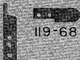
text_image
119-68119-70
text_image
18-957119-69 CS337 24-278 24-277 23-3
PLUNGER PARTS

18-952

46-157

17-153


39-95 26-16
natural_image
Pure electrical circuit lines without any symbolsMODEL 150-7
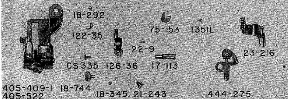
text_image
18-292 122-35 75-153 135IL 22-9 CS 335 126-36 17-113 23-216 405-409-1 18-744 18-345 21-243 444-275 405-522MODEL 150-23
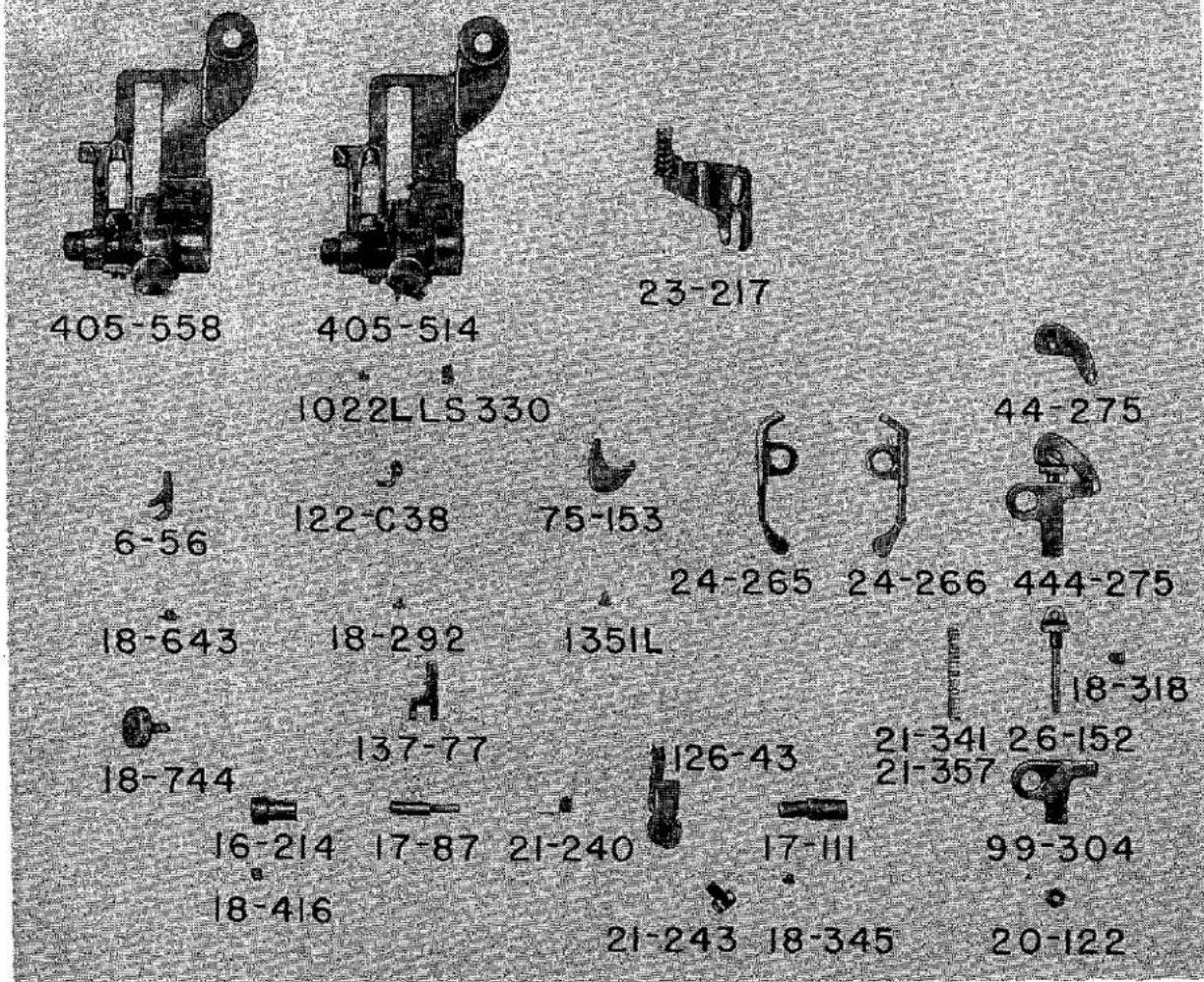
text_image
405-558 405-514 23-217 1022LLS 330 6-56 122-C38 75-153 44-275 24-265 24-266 444-275 18-643 18-292 1351L 18-318 18-744 137-77 126-43 21-341 26-152 16-214 17-87 21-240 21-357 99-304 18-416 17-111 21-243 18-345 20-122FEEDS
| Part No. | Plate | Description |
| MODELS 150-1, 5, 6, 6TS, AND 150-7 | ||
| 23-216 | 22 | Padding, Felling, Hemming, Tacking and Fur Staying. |
| MODEL 150-9 | ||
| 23-310 | 23 | Bookseam, 1/4". |
| 23-311 | 23 | Bookseam, 3/8". |
| MODEL 150-15 | ||
| 23-225 | 23 | Rolled Edge. |
| MODEL 150-16 AND 150-20 | ||
| 23-301 | 24 | Belt Loops. |
| MODEL 150-17 | ||
| 23-217 | 23 | Padding Collars & Lapels. |
| MODEL 150-23 | ||
| Tacking Facing to Forepart (Bluff Edge) | ||
| 23-217 | 25 | Medium and light work. |


FEED PLATES
| Part No. | Plate | Description |
| MODELS 150-1, 5, AND 150-17 | ||
| 24-263 | 22 | Left |
| 24-264 | 22 | Right |
| MODELS 150-6 AND 150-6TS | ||
| 24-270 | 23 | |
| MODELS 150-7 AND 150-23 | ||
| 24-265 | 25 | Left |
| 24-266 | 25 | Right |
| MODEL 150-9 | ||
| 24-294 | 23 | 1/4'' seam |
| 24-295 | 23 | 3/8'' seam |
| MODEL 150-15 | ||
| 24-272 | 23 | |
| MODEL 150-16 | ||
| 24-277 | 16, 24 | Right |
| 24-278 | 16, 24 | Left |
| MODEL 150-20 | ||
| 24-300 | * |
FEED PLATE HOLDERS
| Part No. | Plate | Description |
| MODEL 150-1, 5 AND 150-17 | ||
| 499-298 | 5 | Holder for Right Hand Feed Plate |
| 499-298-1 | 5 | Holder for Left Hand Feed Plate |
| MODELS 150-6 AND 150-6TS | ||
| 499-299 | 10, 11 | Holder for Feed Plate |
| MODELS 150-7 AND 150-23 | ||
| 499-303 | 12, 18 | Holder for Right and Left Hand Feed Plates, (2) used |
| MODEL 150-9 | ||
| 499-298 | 13 | Holder, Right Hand, for Feed Plate |
| 499-302 | 13 | Holder, Left Hand, for Feed Plate |
| MODEL 150-15 | ||
| 499-298 | 14 | Holder for Right Hand Feed Plate |
| 499-302 | 14 | Holder for Left Hand Feed Plate |
| MODEL 150-16 | ||
| 499-298 | 16 | Holder for Right Hand Feed Plate |
| 499-307 | 16 | Holder for Left Hand Feed Plate |
| MODEL 150-20 | ||
| 499-302 | * | Holder for Feed Plate |


FOLDERS
| Part No. | Plate | Description |
| MODEL 150-9 BOOKSEAM | ||
| 431-L175 3/16 | 23 | Light. |
| 431-M175 3/16 | 23 | Medium. |
| 431-175 3/16H | 23 | Heavy. |
| 431-L175 1/4 | 23 | Light. |
| 431-M175 1/4 | 23 | Medium. |
| 431-H175 1/4 | 23 | Heavy. |
| 431-175 5/16L | 23 | Light. |
| 431-175 5/16M | 23 | Medium. |
| 431-175 5/16H | 23 | Heavy. |
| 431-L175 3/8 | 23 | Light. |
| 431-M175 3/8 | 23 | Medium. |
| 431-H175 3/8 | 23 | Heavy. |
| MODEL 150-15 ROLLED EDGE | ||
| 431-147 | 23 | #00 Extra Light Material. |
| 431-148 | 23 | #1 Light Material. |
| 431-149 | 23 | #2 Medium Material. |
| 431-150 | 23 | #3 Heavy Material. |
| 431-159 | 23 | #4 Extra Heavy Material. |
| MODEL 150-16 BELT LOOPS | ||
| 431-169 | 16, 24 | 5/16" Light to Medium Material. |
| 431-170 | 16, 24 | 5/16" Medium to Heavy Material. |
| 431-171 | 16, 24 | 3/8" Light to Medium Material. |
| 431-172 | 16, 24 | 3/8" Medium to Heavy Material. |
| MODEL 150-20 BELT LOOPS | ||
| 431-M180 3/8 | 16 | 3/8" Material. |
| 431-M180 5/16 | 16 | 5/16" Material. |
PRESSER FEET
| Part No. | Plate | Description |
| MODEL 150-1 | ||
| 405-393-2 | 22 | Light. |
| 405-394-4 | 22 | Medium (Standard). |
| 405-395-1 | 22 | Heavy. |
| 405-419 | 22 | Hemming Knit Materials. |
| 405-508 | 22 | Tropicals & Rayons. |
| MODEL 150-5 | ||
| 405-394-8 | 22 | Light & Medium Pants Bottoms (Standard). |
| 405-395-1 | 22 | Heavy Pants Bottoms. |
| 405-529 | 22 | Extra Heavy Pants Bottoms. |
| MODELS 150-6 AND 150-6TS | ||
| 405-502 | 23 | Light, Medium and Heavy. |
| MODEL 150-7 | ||
| 405-409-1 | 25 | Fur Staying and Tacking, Light, Medium and Heavy. |
| 405-522 | 25 | Extra Heavy. |
| MODEL 150-9 | ||
| 405-537 | 23 | 1/4" Bookseam. |
| 405-538 | 23 | 3/8" Bookseam. |
| MODEL 150-15 | ||
| 405-497 | 23 | Rolled Edge. |
| MODEL 150-16 | ||
| Belt Loops. | ||
| 405-517 | 24 | For Light to Medium Material. |
| 405-518 | 24 | For Medium to Heavy Material. |


PRESSER FEET
| Part No. | Plate | Description |
| MODEL 150-17 | ||
| 405-503 | 23 | Padding Collars and Lapels. |
| MODEL 150-20 | ||
| 405-560 | * | Belt Loops. |
| MODEL 150-23 | ||
| 405-514 | 25 | Light and Medium (Standard). |
| 405-558 | 25 | Heavy. |
RIDGE FORMING DISC
| Part No. | Plate | Description |
| MODEL 150-1 | ||
| 44-253 | 22 | Standard-General Work, Padding, Taping and Felling. |
| 44-277 | 22 | Tropicals and Ra yons. |
| 44-278 | 22 | Hemming Knit Materials. |
| 44-287 | * | Extra Heavy Work. |
| MODEL 150-5 | ||
| 44-253 | * | Pants Bottoms, Heavy. |
| 44-296 | 22 | Pants Bottoms, Light and Medium (Std.). |
| MODEL 150-6 | ||
| 44-276 | 23 | Roll Padding. |
| MODEL 150-6TS | ||
| 44-269 | 23 | Roll Padding & Through Stitch. |
| 44-270 | 23 | Roll Padding & Through Stitch. |
| MODELS 150-7 AND 150-23 | ||
| 444-275 | 25 | Fur Staying, Tacking and Bluff Edge. |
| MODEL 150-9 | ||
| 44-291 | 23 | Bookseam. |
| MODEL 150-15 | ||
| 44-272 | 23 | Rolled Edge Hemming. |
| MODEL 150-16 | ||
| 26-160 | 24 | (Plunger) Belt Loops. |
| MODEL 150-17 | ||
| 44-253 | 23 | Padding Collars and Lapels. |
| MODEL 150-20 | ||
| 26-160 | 24 | (Plunger) Belt Loops. |

