ZBD4800XWW - Washing machine GE - Free user manual and instructions
Find the device manual for free ZBD4800XWW GE in PDF.

User questions about ZBD4800XWW GE
0 question about this device. Answer the ones you know or ask your own.
Ask a new question about this device
Download the instructions for your Washing machine in PDF format for free! Find your manual ZBD4800XWW - GE and take your electronic device back in hand. On this page are published all the documents necessary for the use of your device. ZBD4800XWW by GE.
USER MANUAL ZBD4800XWW GE
Before you begin—Read these instructions completely and carefully.
IMPORTANT: Save these instructions for local inspector's use.
IMPORTANT: OBSERVE ALL GOVERNING CODES AND ORDINANCES.
NOTE TO INSTALLER: Be sure to leave these instructions with the Consumer.
NOTE TO CONSUMER: Keep these instructions with your Use and Care Book for future reference.
WARNING
This appliance must be properly grounded. See “Electrical Supply”, page 6.
If the dishwasher is a new installation most of work must be done before the dishwasher is moved into place. If the dishwasher is replacing another dishwasher the connections for the dishwasher being replaced must be checked for compatibility with this dishwasher and replaced as necessary.
If you have a question concerning the installation of this product, call the GE Answer Center® Consumer Information Service at 800.626.2000, 24 hours a day, 7 days a week.
If you received a damaged dishwasher, you should immediately contact your dealer or builder.
Consumer must supply custom panels.
Before you begin: Make sure that custom panels are available. Custom panels must be installed onto the dishwasher before final installation. If they are not, the dishwasher will have to be removed from under the counter to install these panels.
Models ZBD4600X and ZBD4700X have a finished front door and access panel. 1/4" thick custom panels may be installed onto these models.
Models ZBD4800X does not have a finished door or access panel. A custom 3/4" thick door and access panel must be supplied by the consumer.
Installation instructions for both 1/4" and 3/4" thick custom panels are included in this booklet.
Contents
Design Information
Installation Notes 3
Standard Installation in 24" or 25" Deep Cabinets.... 3
Double Dishwashers.... 4
Divider Panel Installation.... 4
Double Dishwashers Water Supply 4
Double Dishwashers Drain Hose, Air Gaps .... 4
Preparation
Choosing the location 5
Dimensions & Specifications 5
Electrical Supply 6
Hot Water Supply 7
Prepare Drain Plumbing 8
Step 1: Check Installation Hardware ...... 9
Tools Required 10
Materials Required 10
Step 2: Remove Packaging .... 10
Models ZBD4600X and ZBD4700X ONLY
Step 3: Prepare 1/4" Custom Panels .... 11
Install Custom Access Panel 11
Insert Custom Door Panel 11
Models ZBD4800X ONLY
Step 3A: 3/4" Door and Access Panels....12
Remove Access Panel Assembly.... 12
Install Custom Access Panel to Assembly .. 13
Remove Plastic Chassis Cover 13
Secure Custom Panel to Dishwasher ... 14, 15
Installation – All Models
Step 4: Adjust The Door Balance ..... 16
Step 5: Install Leveling Legs 16
Step 6: Install Water Inlet Fittings ...... 17
Step 7: Protect the Countertop .... 17
Step 8: Connect Electrical (For Power Cord Installation Only) 17
Step 9: Level the Dishwasher 18
Step 10: Install Side Filler Strips 18
Step 11: Connect Drain Hose .... 18
Step 12: Slide Dishwasher Into Opening ..... 18
Step 13: Connect Water Line .... 19
Step 14: Install Drain Line .... 19
Step 15: Connect Electrical (For direct Connection to House Wiring) 20
Step 16: Secure Dishwasher to Countertop ..... 20
Step 17: Reinstall Chassis Cover 20
Step 18: Install Toekick and Access Panel ...... 21
Install Optional Custom Toekick.... 21
Finalize Installation 21
Questions & Answers 23
Design Information
| Stainless Steel Interior Dishwashers | ||
| Installation Notes | Models ZBD4600X and ZBD4700X dishwashers are supplied as either a black or white model. Door and access panels may be replaced with custom decorative panels of wood or other materials to match surrounding cabinetry.• Standard door and access panel trim will accommodate custom panels up to 1/4" thick. | Model ZBD4800X dishwashers are supplied as either a black or white model. These models do not have a finished door or access panel. A custom 3/4" thick door and access panel must be custom made to suit the installation.• All dishwasher models may be installed beneath any type of countertop.• A matching toekick is supplied with all models and may be customized to match surrounding cabinetry.• Side trim is not required. All models come equipped with vinyl strips to fill a 24" wide opening. |
| Standard Installation in 24" or 25" deep cabinets | Models ZBD4600X and ZBD4700X as supplied:• The dishwasher door will be flush with the front face of the cabinetry.• The dishwasher control panel will extend 1/4" beyond the front face of cabinetry. The addition of a 1/4" thick custom door and access panel will make the door and control panel nearly flush.Models ZBD4800X:• With the 3/4" thick custom panel in place, the exterior is trimless and fits flush with adjacent cabinetry. |  |
Design Information
| Stainless Steel Interior Dishwashers | ||
| Double Dishwashers | When installing double dishwashers side-by-side:Make cabinet opening 47-3/ 8" wide.Depth and height are same as for single unit. | 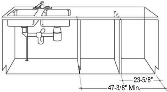 |
| Divider Panel Installation | Must be supplied by installer at time of installation. Locate divider panel in center of 47-3/ 8" opening provided for two dishwashers.Suggest attachment to floor, countertop and rear wall. | 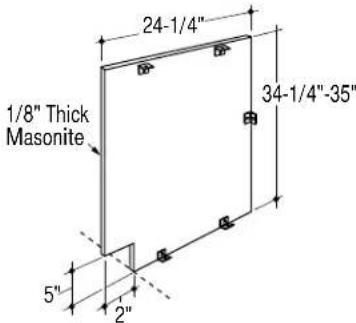 |
| Double Dishwashers Water Supply | When installing two dishwashers side-by-side, run a branch water supply line as shown. | 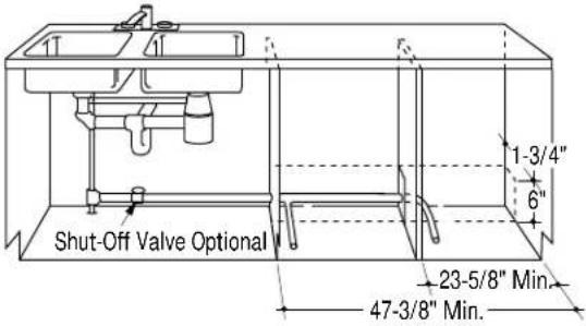 |
| Double Dishwashers Drain Hose, Air Gaps | When installing two dishwashers side-by-side, place drain hoses and air gaps as shown. |  |
| Note: Each dishwasher must have a separate drain hose as shown. | ||
Choosing the Location
Select a location as close to the sink as possible for easy access to water and drain lines.
- The dishwasher must be located within reach of the drain hose. The maximum drain hose length is 10 feet. Consideration for the installation of a high drain loop or air gap must be included when determining the installation location. See "Prepare Drain Plumbing", page 8 and "Install Drain Plumbing", page 19.
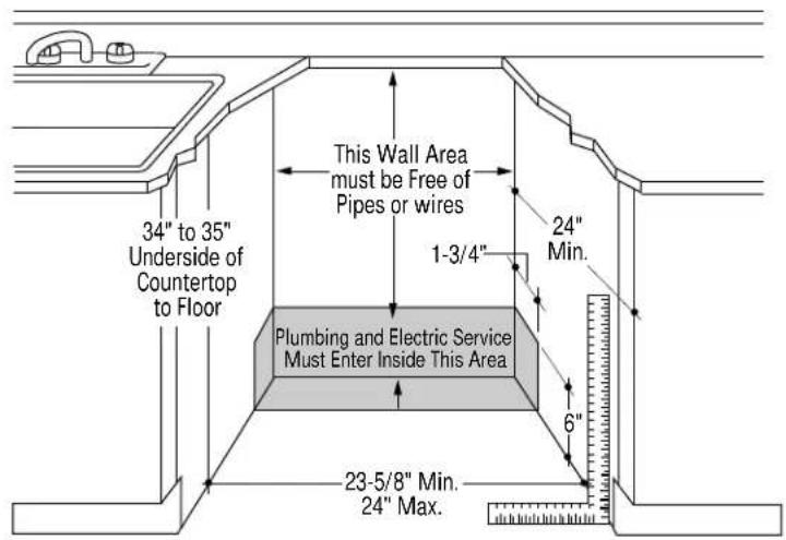
- The rough opening should be 23-5/8" min. to 24" max. wide, 24" deep and 34" to 35" high.
text_image
34" to 35" Underside of Countertop to Floor This Wall Area must be Free of Pipes or wires 1-3/4" 24" Min. Plumbing and Electric Service Must Enter Inside This Area 6" 23-5/8" Min. 24" Max.- Adjacent cabinets should be square and plumb to ensure a good fit.
• The floor inside the opening must be level and even with the kitchen floor. - The dishwasher must be fully enclosed on the top, sides and back.
- Filler strips are provided to cover gaps on the sides of dishwasher.
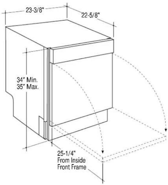
Dimensions & Clearances
If the dishwasher is installed in a corner, allow 2" min. clearance between dishwasher and adjacent cabinet, wall or other appliances.
text_image
23-3/8" 22-5/8" 34" Min. 35" Max. 25-1/4" From Inside Front FrameElectrical Supply

Warning, for Personal Safety:
Remove house fuse or open circuit breaker
before beginning installation.
Do not use an extension cord or adapter plug with this appliance. Follow National electrical codes or prevailing local codes and ordinances.
text_image
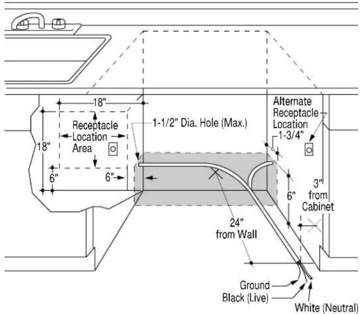
18" Receptacle Location Area 1-1/2" Dia. Hole (Max.) Alternate Receptacle Location 1-3/4" 6" 6" 3" from Cabinet 24" from Wall Ground Black (Live) White (Neutral)Electrical Requirements
- This appliance must be supplied with 120V, 60 Hz., and connected to an individual, properly grounded branch circuit, protected by a 15 or 20 ampere circuit breaker or time delay fuse.
• Wiring must be 2 wire with ground. - If the electrical supply provided does not meet the above requirements, call a licensed electrician before proceeding.
- A side-by-side dual installation requires two separate circuits.
Grounding Instruction
This appliance must be connected to a ground metal, permanent wiring system, or an equipment-grounding terminal or lead on the appliance.

Warning: The improper connection of the equipment-grounding conductor can result in a risk of electric shock. Check with a qualified electrician or service
representative if you are in doubt whether the appliance is properly grounded.
Cabinet Preparation & Wire Routing
- Wiring may enter from either side of the opening, from the rear, or from the floor within the shaded area shown.
- Cut hole 1-1/2" max. dia. within the shaded area to admit the electrical cable or power cord. The hole must be free of sharp edges. If the cabinet wall partition is metal, the edge of the hole must be covered with a rubber cord protector.
Electrical Connections to Dishwasher
- For cable direct connections the cable must be routed as shown in the diagram. Cable must extend a minimum of 24" from the rear wall.
- For power cord connections, install a 3-prong grounding type receptacle in the rear wall of sink cabinet next to the dishwasher. The receptacle should be installed at least 6", but not more than 18", from the cabinet opening for dishwasher. Power cord must be no longer than 6 feet from the junction box to the plug.
Hot Water Supply
The hot water supply line may enter from either side, the rear or from the floor within the shaded area.

text_image
1-1/2" Dia. Hole Shut-off Valve Hot Cabinet Face Left Side Entry Approx. 30" from Wall Right Side Entry Approx. 40" from Wall 1-3/4" 6" 2" from Floor- Turn off the water supply.
- Cut a hole approximately 1-1/2" dia. within the shaded area to admit the water line. Access holes must be round and smooth.
• Install a hand shut-off valve in the hot water supply line in an accessible location, such as under the sink. (The shut-off valve is optional, but recommended and may be required in some local codes.)
• Install the hot water inlet line, using no less than 3/8" O.D. copper tubing or 1/2" O.D. plastic tubing.
- The water line must be long enough to form a smooth natural loop with no sharp bends or kinks between the cutout entry and fill valve location. For a left side entry, allow approximately 30" length. For a right side entry, allow approximately 40" length.
- Extend the water line forward to approximate fill valve location.
- Adjust the water heater to deliver 120°F min. water temperature.
- The water pressure of the hot water supply line must be 20 to 120 psi.
Prepare Drain Plumbing
DRAIN REQUIREMENTS
- Follow local codes and ordinances.
- Dishwasher drain hose must not exceed 10 feet in length for proper drainage.
- Dishwasher must be connected to waste line with an air gap (not supplied) or 32" minimum high drain loop depending on local codes and ordinances to prevent back flow into the dishwasher.
- Air gap must be used if waste tee or disposer connection is less than 18 inches above floor to prevent shopping.
DRAIN PREPARATION
The type of drain installation depends on answers to the following questions:
1 Do local codes or ordinances require an air gap?
1 Will waste tee or disposer connection be less than 18" above floor?
1 Will installation have a drain loop less than 32" above floor?
If the answer to ANY of the 3 questions above is YES, Method 2 MUST be used. Otherwise either Method 1 or Method 2 may be used.

CAUTION
An air gap MUST BE USED if the drain hose is connected to waste tee or disposer lower than 18" above the floor level.
Failure to provide the proper drain connection height with air gap or 32" minimum height drain loop will result in improper draining of the dishwasher which may cause damage.
METHOD 1-High Drain Loop with Waste Tee or Disposer

METHOD 2-Air Gap with Waste Tee or Disposer

natural_image
Technical line drawing of a mechanical or electrical component with pipes and housing (no text or symbols)
natural_image
Technical line drawing of a mechanical assembly with no visible text or symbolsInstall air gap, waste tee or disposer according to manufacturer's instructions. Provide a method to support drain hose at least 32" above floor to prevent back flow into dishwasher.

Check
Installation
Hardware
Remove the hardware accessory bag and other parts from inside or taped to the outside of the dishwasher. Check contents against drawings to assure that all parts are present.
All Models

text_image
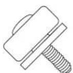
4 Leveling Legs 2 Screws to Secure Dishwasher to Countertop Screw Type Hose Clamp 4 Lock Washers 4 Nuts Side Filler Strips Clear Plastic Self-Adhesive Countertop Shield 1/2" Water Inlet Extension Fitting, 3/8" NPT both top and bottom 2 Slides Corrugated Drain Hose Color Matched Toekick (taped to the outside of dishwasher)Model ZBD4800X Only

text_image
2 Metal Door Panel Mounting Brackets 2 Access Panel Mounting Brackets 2 Plastic Door Panel Mounting Brackets Screws A 4 Flathead Phillips Screws for Access Panel Brackets Screws B 16 Round Head Phillips Screws for Door Panel Brackets Screws C 2 Screws to Secure Custom Panel to Dishwasher Door Door Panel Template Template for Custom Door and Access Panel Taped to the Outside of the Dishwasher Access Panel Template Actual Size Screw A Screw B Screw CStainless Steel Interior Dishwashers
If you have a question concerning the installation of this product, call the GE Answer Center® Consumer Information Service at 800.626.2000, 24 hours a day, 7 days a week.

If you received a damaged dishwasher, you should immediately contact your dealer or builder.
Installation of this dishwasher requires basic electrical and mechanical skills. Proper installation is the responsibility of the installer. Product failure due to improper installation is not covered under the GE Appliance Warranty. See the back cover of the Use & Care Guide for warranty information.
The dishwasher MUST be installed in such a manner to allow for future removal from the enclosure if service is required.
Before starting make sure that the custom panel is available. If not, the dishwasher will have to be removed from under the counter to install the panels.
Tools Required (not supplied)
Materials Required (not supplied)
- Tape measure
- Spirit level
- Flat blade screwdriver
• Phillips screwdriver
• Awl
- Carpenters square
- Wire cutter
- Adjustable wrench
-
Wire stripper
-
Electric drill
• 1-1/2" drill bit or hole saw
• Pliers
Step 2 Remove Packaging
• Minimum 3/8" OD copper tubing of sufficient length for your installation
- Shut-off valve
- Compression nut
- Compression sleeve
- 90° compression elbow (3/8" NPT one end)
- Two 1-1/4" adjustable hose clamps (to accommodate drain line)
• 120 Volt 60 Hz. 15 Amp or 20 Amp, 2 wire with ground
Properly grounded branch circuit
- 1/2" strain relief bushing for electrical supply cable.
- 3 wire nuts
Cut the shipping carton and use it as a pad under the dishwasher. This will protect the finished flooring of the room.
- Remove the toekick taped to the top of the dishwasher.
- Remove the template taped to the side (on Model ZBD4800X only).
- Lay the dishwasher on its back close to the opening.
- Place a 2x4 block or two corner posts from packaging beneath the dishwasher. This will prevent the dishwasher from falling when the shipping bolts are removed.
- Remove 4 shipping bolts with an adjustable wrench and discard.
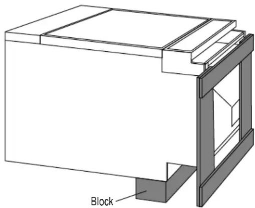
text_image
BlockStep 3
Prepare 1/4" Custom Panels
For Model ZBD4600X and ZBD4700X ONLY
Models ZBD4600X and ZBD4700X will accept 1/4" thick custom door and access panels.
- Cut 1/4" thick door panel: 23-1/4" wide, 22-11/16" high.
- Cut 1/4" thick access panel: 23-1/4" wide, 1-1/2" high.
Cut edges of the panels will be concealed by the trim.
Cut a notch in the top corners of the door panel, 1/8" wide and 3/16" deep. This will allow the panel to slide under the escutcheon. The bottom corners of the door panel trim and all 4 corners of the access panel trim are rounded. Therefore, for a good fit, a 5/16" radius cut is required.

text_image
Notch 1/8" 3/16" 1/4" Thick Door Panel 22-11/16" 5/16" Radius Cut 1/4" Thick Access Panel 1-1/2" 23-1/4"Install Custom Access Panel
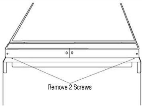
text_image
Remove 2 Screws- Remove the two screws below the access panel assembly and lift off.
- Remove the 4 Phillips head color matched screws on the bottom side of the assembly and 2 screws on the top.
- Lift off the trim piece.
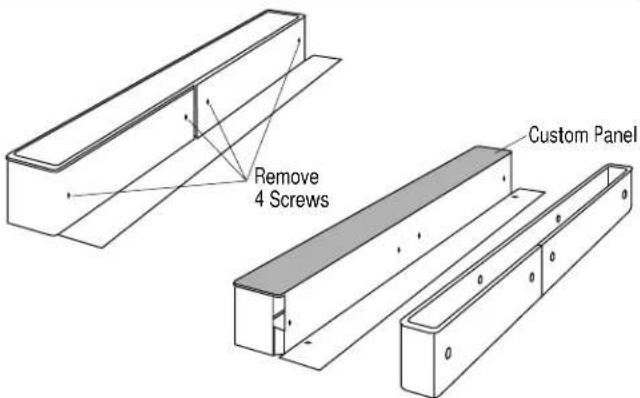
text_image
Remove 4 Screws Custom Panel- Place the custom panel on top of the assembly and reinstall the trim with the same color matched screws.
- Set the assembled access panel aside. Do not reinstall this piece until final installation is complete.
Insert Custom Door Panel
- Remove 2 Phillips head color matched screws on each side of the door trim.
- Remove 2 screws on the bottom of the door trim.
- Slide the door trim down and remove.
- Slide the 1/4" thick custom panel under the escutcheon lip. Making sure the panel is centered left to right.
- Re-install the door trim using the screws previously removed.
Important: Do not overtighten screws. Hand-tighten with a Phillips head screwdriver.
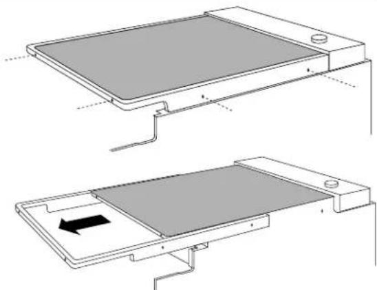
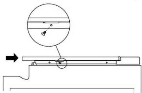
natural_image
Technical line drawing of a flat-panel electronic device with a black arrow indicating a component (no text or symbols present)3/4" Custom Panels
Models ZBD4800X do not have a finished door or access panel. 3/4" thick custom panels are required.
Models ZBD4800X Dishwashers
Step 3A
3/4" Door and
Access Panels
For Model
ZBD4800X
ONLY
Skip This Step
If You Are
Installing Other
Models
Door and access panels should be constructed in the same manner as surrounding cabinetry. Cut edges will show and must be finished for optimum appearance. Provide these dimensions to the cabinet manufacturer to ensure that the panels are constructed accurately.
This dishwasher has an adjustable spacer bar below the control panel. The spacer bar allows you to match the height of adjacent drawers. When adjacent drawers are shorter height than the control panel, align the bottom of the control panel by pushing the spacer bar upwards and tightening two screws. Maximum spacer bar adjustment is 3/4".

text_image
4-3/4" 5-1/2" Spacer Bar Adjustment ScrewsAny adjustment to the spacer bar will affect the height of the custom panel.
EXAMPLE: Minimum panel height is 22-1/2"
Add adjusted dimension 1/4"
TOTAL PANEL HEIGHT 22-3/4"
OR
Measure the adjusted height of the control panel. Subtract that dimension from 28". The panel height will be 22-1/2" Min. to 23-1/4" Max.

text_image
3/4" Thick Door Panel 22-1/2" Min. 23-1/4" Max. See Example 3/8" Gap 3/4" Thick Access Panel 1-5/8" 23-3/8"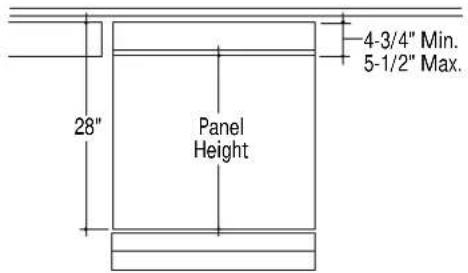
text_image
4-3/4" Min. 5-1/2" Max. 28" Panel HeightRemove
Access Panel
Assembly

text_image
Remove 2 Screws- Remove the two screws below the access panel assembly.
- Lift the assembly off and set aside.
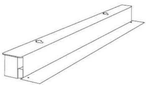
natural_image
Technical line drawing of a structural beam or panel with two flanged ends and a central rectangular cutout (no text or symbols)Step 3A
(continued)
Install
Custom
Access Panel
to Assembly
Locate the access panel template provided.
- Place the template on the back side of custom access panel with top edges and sides aligned.
- Use an awl or punch to mark 4 screw hole locations.
- Remove the template and drill four 3/32" pilot holes 3/8" deep in the marked locations.
- Place the mounting brackets on the access panel, aligning screw holes.
- Secure the brackets to the panel with four screws (A) provided.
- Drop the access panel with mounting brackets into the slots on the assembly and push down.
- Set the access panel assembly and custom panel aside. Do not reinstall until final installation is completed.
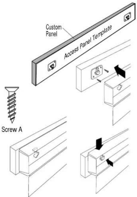
text_image
Custom Panel Access Panel Template Screw ARemove
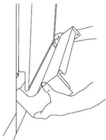
Plastic
Chassis
Cover
text_image
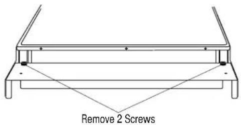
Remove 2 ScrewsRemove the two screws with spacers on each side of the plastic chassis cover.
- Lift and rotate upwards until the chassis cover snaps out of position. Remove and set aside. Do not re-install until final installation is completed.

natural_image
Line drawing of a hand using a tool to lift a metal frame, with an arrow indicating rotation (no text or symbols)3A (continued)
Secure Custom Panel to Dishwasher
Use the template supplied to find the location of the support brackets which hold the custom panel to the front of the dishwasher door.
- Check to be sure the spacer bar below the control panel is set to the desired location.
- Measure the total height of the control panel. See illustration on page 12.
-
Find and mark that location on the graded rule on both top corners of the template.
-
Lay the custom panel on a flat surface with the appearance side down. Locate the vertical center of the panel at the top. Use a carpenters square to draw a center line from top to bottom on the panel.
- Place the template on the panel with the large "V" notch at the top and small "V" notch at bottom. Align the template center line to the center line drawn on the panel. Align the top of the template with dimensions previously marked on the graded rules. The windows on both sides of the template will help you align the template to the panel accurately.
- Tape the template in place and use an awl to mark screw hole locations indicated.
- Remove the template and drill pilot holes 3/32" deep in the marked locations.
- Secure all brackets to the custom panel using Screws (B) provided.

text_image
MM INCHES CONTROL PANEL HEIGHT 115 4-3/4 125 5 135 5-1/4 145 5-1/2 155
natural_image
Pure technical line drawing of a rectangular block with a vertical dashed line and a stepped corner (no text or symbols)
natural_image
Isometric technical diagram of a mechanical assembly with a magnified inset showing internal components (no text or symbols)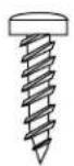
Screw B
natural_image
Isometric line drawing of a square plate with four corner mounting holes (no text or symbols)3A (continued)
- Fit the panel to the door by inserting the top and bottom mounting brackets into the matching slots.
- The top plastic brackets will fit into keyhole slots and the bottom metal brackets will fit into the side slots.
- Press the panel against the door and push upwards until the side bracket screw hole aligns with the inner door screw hole on both sides.
• Install one screw (C) on both sides to secure the panel to the door.
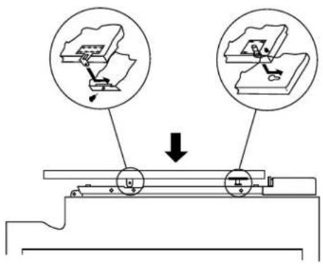
text_image
Technical diagram showing mechanical assembly with two circular insets and a downward arrow indicating motion or force direction.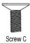
natural_image
Technical diagram of a mechanical assembly with a magnified circular detail showing internal components and an arrow indicating direction (no text or labels)Step 4 Adjust The Door Balance
- Carefully upright the dishwasher.
Important: The weight of the door panel may cause the door to fall heavily. The correct spring tension will prevent the door from falling too heavily or raising by itself from a fully open position.
- Hold the door and open fully. If the door falls too heavily, or if the door starts to close by itself, the spring tension will need to be adjusted.
If adjustment is required:
• To locate the spring adjustment slots, carefully lay the dishwasher on its back.
- Remove the 3 screws holding the base plate to the bottom of the dishwasher.
- Locate the spring tension slots on the sides.
- With a pair of pliers, pull the spring clip out and down to the next slot for more tension, or up to the next slot for less tension.
- Upright the dishwasher and test door balance. Continue this procedure until the door is balanced.
- Reinstall the base plate with screws.
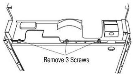
text_image
Remove 3 Screws
text_image
Spring Clip5 Step Install Leveling Legs
Locate the 4 leveling legs, 4 nuts and 4 locking washers.
• Install a nut followed by a lock washer onto each leveling leg.
- Insert the leveling leg into the bottom of the dishwasher. Screw the leg in until the total dishwasher height nearly matches cutout height.
- Screw the nut up against the bottom of the dishwasher, do not tighten until final installation is completed.
If the plastic chassis cover has not been removed, do so at this time. See page 13, "Remove plastic chassis cover."
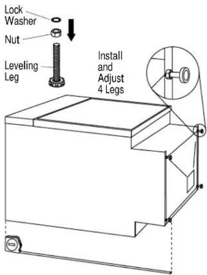
text_image
Lock Washer Nut Leveling Leg Install and Adjust 4 LegsInstallation
Stainless Steel Interior Dishwashers
Step 6
Install
Water Inlet
Fittings
Step 7
Protect the
Countertop
• Install the water inlet extension fitting and 90° elbow (not supplied) onto the dishwasher. Use thread sealing tape or pipe thread compound.
- The 90^ elbow should face the left side of the dishwasher.

text_image
Note: 90° elbow would face the left e.Note: 90° elbow should face the left side.
• To protect the countertop from moisture, apply the self-adhesive plastic strip provided to the underside of the countertop.
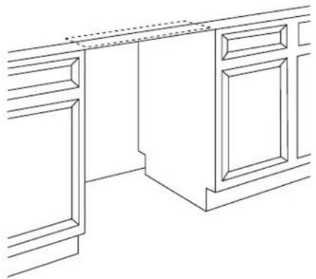
natural_image
Line drawing of a cabinet or cabinet frame with decorative trim and doorways (no text or symbols)Step 8
Connect
Electrical
(For Power Cord Installation Only)
- Remove the screw holding the junction box to the dishwasher frame. Remove the junction box.
- Install a strain relief onto the junction box.
- Tighten the strain relief against the incoming wires.
- Strip 1/2" insulation from end of wires.
- Connect incoming wires to dishwasher wires using wire nuts of appropriate size. Connect white to white, black to black and incoming ground to green wire.
- Push all wires into the junction box and place on dishwasher frame. Secure with screw.
Note: The power cord and connection must comply with the National Electrical Code, Section 422 and/or local codes and ordinances.
IMPORTANT: Power cord must be no longer than 6 feet from the junction box to the plug. Do not plug in power cord at this time.
text_image
Screw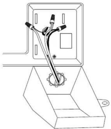
natural_image
Technical line drawing of a mechanical assembly with a central component and base mount (no text or symbols)Installation
Stainless Steel Interior Dishwashers

- Carefully upright the dishwasher, so as not to bend the leveling legs.
- Tilt the dishwasher slightly and slip leg slides under the leveling legs.
- Check to be sure the dishwasher is level and at the proper cutout height.
- Tighten the bolts on each leveling leg against the bottom of the dishwasher.

text_image
Level Top And Sides Leg Slides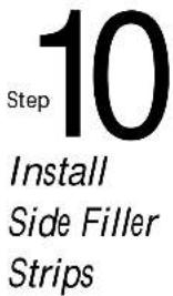
text_image
Step 10 Install Side Filler StripsSide filler strips are packed with the product. If the cabinet cutout is wider than the dishwasher, install the filler strips on both sides of the dishwasher to cover gaps.
- Open the door fully.
- Remove the two screws on the inside front frame of the dishwasher.
- Remove the plastic covering the adhesive strip on the back side of the filler strip.
- Carefully, align the screw holes on the filler strip with screw holes on the dishwasher. Press firmly into place.
- Secure filler strips with original screws.

natural_image
Line drawing of a simple bed or storage unit with no text, numbers, or symbols
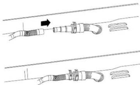
Locate the drain hose packed with the dishwasher.
- Fit the drain hose onto the drain hose adapter on the back of the dishwasher.
- Press together firmly and secure with a screw type clamp supplied.
natural_image
Diagram showing three sequential steps of a cable or connector assembly with no visible text or symbols
text_image
Step 12 Slide Dishwasher Into Opening- Insert the drain hose into the cabinet wall.
- Slide the dishwasher into the opening a few inches at a time.
- As you proceed, pull the drain hose through the cabinet wall under the sink.
- If a power cord has been installed, insert the cord through a separate hole in the cabinet wall and pull along with drain hose.
- Check to be sure there is no interference with waterline or house wiring.

text_image
Leg SlidesInstallation
Stainless Steel Interior Dishwashers
The water supply line should be flushed to clear any foreign material before connecting to the dishwasher.
- Make sure there are no sharp bends or kinks which could restrict the water flow.
- Connect the water supply line to the 90° elbow.
- Turn on the water supply and check for leaks.
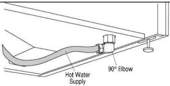
text_image
Hot Water Supply 90° ElbowFollow all local codes and ordinances.
Drain Line Preparation
- The dishwasher is supplied with a 78" long corrugated drain hose. The molded end is designed to fit 5/8", 3/4" or 1" diameter connections to the air gap, waste tee or disposer. Cut on premarked line as required for your installation.
Note: Do not cut corrugated portion of hose.

text_image
Cutting Lines 1" 3/4" 5/8" Do not cut corrugated portion of hose- If the location requires a longer drain hose, add up to 42" length to the supplied hose. Use 5/8" inside diameter hose and thin wall copper coupler to join the hose ends.
Note: Total drain hose length must not exceed 10 feet for proper drain operation.
Drain Line Installation
- Connect drain line to air gap, waste tee or disposer using either Method 1 or Method 2 as previously determined.
- Secure connection using appropriate clamps (not supplied).
- Make sure drain hose is not kinked.
Method 1-High drain loop with waste tee or disposer

text_image
Fasten to underside of countertop 18" Min. 32" Min.
text_image
Fasten to underside of countertop 18" Min. 32" Min.Waste tee installation Disposer Installation
Note: Be sure to remove drain plug from disposer before attaching drain line. Dishwasher will not drain if plug is left in place.
Method 2-Air gap with waste tee or disposer

natural_image
Technical line drawing of a mechanical assembly with pipes and housing (no text or symbols)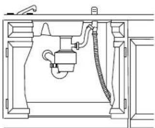
natural_image
Technical line drawing of a mechanical assembly with pipes and housing (no text or symbols)Waste tee installation Disposer Installation
Step 15
Connect Electrical (For direct connection to house wiring)
Verify that power is turned off at source.
WARNING

If house wiring is not 2-wire with a ground wire, a ground must be provided by the installer. When house wiring is aluminum, be sure to use U.L. approved antioxidant compound and aluminum-to-copper connectors.
- Remove the screw holding the junction box to the dishwasher frame. Remove the junction box.
• Install a strain relief onto the junction box. - Tighten the strain relief against the incoming wires.
- Strip 1/2" insulation from end of wires.
- Connect incoming wires to dishwasher wires using wire nuts of appropriate size. Connect white to white, black to black and incoming ground to green wire.
- Push all wires into the junction box and place on dishwasher frame. Secure with screw.

text_image
Screw
natural_image
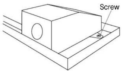
Technical line drawing of a mechanical assembly with a tool inserted into a housing (no text or symbols)Step 16
Secure Dishwasher to Countertop
To maintain dishwasher position and alignment, drill pilot holes through the mounting flange and into the underside of the countertop. Install 2 screws provided.
Note: Open and close dishwasher door to insure proper clearance between tub and door. If there is any binding or rubbing, readjust leveling legs.

natural_image
Line drawing of a cabinet interior with an open drawer and internal shelving unit (no text or symbols)Step 17
Reinstall Chassis Cover
- To reinstall the plastic chassis cover, tilt and rotate the cover under the door. Press the bottom of the cover against the metal frame of the dishwasher until it fits into position.
- Secure the cover to the dishwasher using the two screws with attached spacers.
NOTE: The small ring of the spacer goes against the chassis cover.
natural_image
Line drawing of a hand holding a tool with a bracket, no text or symbols presentInstallation
Stainless Steel Interior Dishwashers
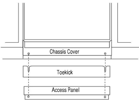
18 Step Install Toekick and Access Panel
- Place the toekick against the chassis cover, aligning screw holes.
- Hang the access panel assembly on the screw with the spacer ring. The lip of the assembly will slip into the notch on the ring.
- Secure the assembly with the original Phillips head color matched screws.
text_image
Chassis Cover Toekick Access PanelOptional Custom Toekick
The supplied toekick may be covered with a custom toekick to match surrounding cabinetry.
BEFORE YOU BEGIN:
- Install the supplied toekick as described above.
- Compare the toekick depth of the dishwasher to the toekick depth of the cabinetry. Cabinet toekick depth will vary among manufacturers.
- The difference will determine the thickness of the custom material to be used.
- Cut the custom toekick to fit the width of the dishwasher opening.
A continuous toekick, bridging the dishwasher cutout can be used if cabinet toekick depth is not less than the dishwasher depth. Secure the continuous toekick in such a manner that it could be removed if service is required.
Finalize Installation
- Turn on the hot water shut-off valve and electrical supply.
- Operate dishwasher through one cycle and check for plumbing leaks.
- Leave Installation Instructions and Use & Care literature with the owner.
- Discard any unused parts.
Q. Can I use a custom toekick with the stainless steel interior dishwasher models?
A. Yes, a matching toekick is supplied with these models and can be covered with a custom toekick to match surrounding cabinetry.
Q. Can I use custom panels on the stainless steel interior dishwasher models?
A. Yes, Models ZBD4600X and ZBD4700X will accept 1/4" thick custom panels. The custom panels are secured to the dishwasher with the factory installed trim and does not require a trim kit.
Models ZBD4800X do not have a finished door or access panel.
These models require a 3/4" thick custom door and access panel.
Mounting brackets for the panels are provided with the product. The installation of custom panels on all models must be completed before the product is installed.
Note: While performing installations described in this book, safety glasses or goggles should be worn.
To obtain specific information concerning any Monogram product or service, call GE Answer Center® consumer information service at 800.626.2000—any time, day or night.
For Monogram local service in your area, call 1-800-444-1845.
NOTE: Product improvement is a continuing endeavor at General Electric. Therefore, materials, appearance and specifications are subject to change without notice.
Pub. No. 49-5774
Dwg. No. 165D4700P122
1996 GE Appliances
(N.D. 466) 9/96