63900S - Sewing machine Union Special - Free user manual and instructions
Find the device manual for free 63900S Union Special in PDF.

User questions about 63900S Union Special
0 question about this device. Answer the ones you know or ask your own.
Ask a new question about this device
Download the instructions for your Sewing machine in PDF format for free! Find your manual 63900S - Union Special and take your electronic device back in hand. On this page are published all the documents necessary for the use of your device. 63900S by Union Special.
USER MANUAL 63900S Union Special
Union Special INDUSTRIAL SEWING EQUIPMENT
CATALOG NO. 126P
STYLES
63900R
63900S
63900 CLASS
STREAMLINED
HIGH SPEED NEEDLE FEED
LOCKSTITCH MACHINES
WITH
Catalog No. 126 P (Supplement to Catalog No. 126 M)
INSTRUCTIONS
FOR
ADJUSTING AND OPERATING
LIST OF PARTS
CLASS 63900
Needle Feed Streamlined Lockstitch
Styles 63900 R 63900 S
First Edition
Copyright 1970 by Union Special Machine Co. Rights Reserved in All Countries
UnionSpecial
MACHINE COMPANY
INDUSTRIAL SEWING MACHINES
CHICAGO
Printed in U.S.A.
December, 1970
IDENTIFICATION OF MACHINES
Each Union Special machine is identified by a Style number on a name plate on the machine. Style numbers are classified as standard and special. Standard Style numbers have one or more letters suffixed, but never contain the letter "Z". Example: "Style 63900 R". Special Style numbers contain the letter "Z". When only minor changes are made in a standard machine, a "Z" is suffixed to the Standard Style number. Example: "Style 63900 RZ".
Styles of machines similar in construction are grouped under a class number which differs from the style number, in that it contains no letters. Example: "63900".
APPLICATION OF CATALOG
This catalog is a supplement to Catalog No. 126 M (Second Edition) and should be used in conjunction therewith. Only those parts which are used on Styles 63900 R and S, but not used on Styles 63900 C or D are illustrated and listed at the back of this book. For clarity, certain 63900 C or D parts are shown in phantom to help locate the 63900 R and S parts.
Opposite the illustration page, parts are identified by detail number, part number, description and amount required.
NOTE: When ordering repair parts always use the part number listed in the second column.
Adjusting and operating instructions for Styles 63900 R and S are similar to those in Catalog No. 126 M (Second Edition) for Styles 63900 C and D respectively. The only instructions included in this catalog are the ones that are different from Styles 63900 C and D, or are additional instructions that pertain specifically to Styles 63900 R and S.
The catalog applies specifically to the Standard Styles of machines as listed herein. It can also be applied with discretion to some Special Styles of machines in this class. Reference to direction, such as right, left, front, back, etc., are given from the operator's position while seated at the machine. Operating direction of handwheel is toward the operator.
STYLES OF MACHINES
High Speed Streamlined Long Arm Needle Feed Lockstitch Machines, One Needle, Light, Medium and Heavy Duty, Drop Feed, Rotary Hook, Horizontal Hook Shaft, Push Button Stitch Regulator, Slotted Segment for Adjusting Needle Feed, Stitch Length Indicator, One Reservoir Enclosed Automatic Lubricating System, Head Oil Siphon, Adjustable Hook Oil Control, Needle Bearing Adjustable Feed Eccentric, Needle Bearings for Take-up Lever and Needle Bar Driving Link, Feed Timing on Lower Main Shaft, Needle Feed Timing on Upper Shaft, Maximum Work Space to Right of Needle Bar 11 1/8 Inches.
63900 R Fitted with top driven roller feed and rotary tension for needle thread. For operations on light to medium weight material, where a roller feed is advantageous on hard to handle or easily puckered material. 1 9/64 inch needle bar travel. Type 183 GXS or 183 GYS needles. Seam specification 301-SSa-1. Specify presser foot, throat plate, feed dog, attachments, guides, needle type and size. Maximum recommended speed 5500 R.P.M.
63900 S Fitted with top driven roller feed and rotary tension for needle thread. For operations on medium to medium heavy weight material, where a roller feed is advantageous on hard to handle or easily puckered material. 1 13/64 inch needle bar travel. Type 180 GXS or 180 GYS needles. Seam specification 301-SSa-1. Specify presser foot, throat plate, feed dog, attachments, guides, needle type and size. Maximum recommended speed 5500 R.P.M.
NOTE: For the number necessary to complete the Styling of these 63900 machines, refer to Pages 4 and 5. The number indicates a certain sewing combination - presser foot, throat plate and feed dog. Specify the needle hole size if more than one is available.
(AFTER EACH STYLE NUMBER IS LISTED THE PRESSER FOOT, THROAT PLATE AND FEED DOG MAKING UP THE SPECIFIC STYLE. WHERE MORE THAN ONE PART NUMBER IS SHOWN FOR A SPECIFIC STYLE, ONLY ONE WILL BE FURNISHED WITH EACH MACHINE. IN ALL CASES, THE STYLE NUMBER WILL BE LISTED AND THE PRESSER FOOT, FEED DOG AND THROAT PLATE MUST ALSO BE LISTED ON S.R.)
| STYLE NUMBER | PRESSER FOOT | FEED DOG | THROAT PLATE | STITCH RANGE |
| 1 | 61920 L | 61926 D | *61928 B | 12-16 |
| 2 | 61920 S | 61926 D | *61928 B | 12-16 |
| 2-A | L440 A | |||
| 2-B | 61920 M | |||
| 3 | 61920 B | 61926 | *61928 | 11-18 |
| 3-A | 61920 S | |||
| 4 | 61927 A | 61926 A | *61928 A | 11-18 |
| 4-A | 61320 P | |||
| 4-B | 61420 R | |||
| 4-C | 61920 B | |||
| 5 | 61420 BT | 61905 B-063 or 073 or 083 | 61924 B | 7-18 |
| 5-A | L440 A | |||
| 6 | 61920 F | 61905 F-063 | 61924 C | 7-18 |
| 7 | 61920 J | 61926 | *61928 | 11-18 |
| 7-A | L471 A | |||
| 7-B | 61920 P | |||
| 8 | 61920 B | 61905 J-063 | 61924 J | 7-18 |
| 9 | 61920 J | 61905 J-063 | 61924 J | 7-18 |
| 9-A | L471 A | |||
| 10 | 61920 A | 61905 C-073 | 61924 C | 7-18 |
| 10-A | 61920 S | |||
| 11 | 61920 C | 61905 C-073 | 61924 C | 7-18 |
| 12 | 61920 S | 61905 K-073 or 083 | 61924 K | 7-18 |
| 12-A | 61920 A | |||
| 12-B | 61320 P | |||
| 13 | 61920 J | 61905 E-073 | 61924 E | 7-18 |
| 14 | 61920 J | 61905 G-073 or 083 | 61924 G | 7-18 |
| 15 | 61920 A | 61905 B-063 or 073 or 083 | 61924 B | 7-18 |
| 16 | 61920 R | 61905 J-063 | 61924 J | 7-18 |
| 17 | 61920 N | 61926 D | *61928 B | 12-16 |
| 18 | 61420 BT | 61926 | *61928 | 11-18 |
| 18-A | 61920 C | |||
| 19 | L310 A | 61926 | *61928 | 11-18 |
| 20 | 61320 P | 61905 E-073 | 61924 E | 7-18 |
| 20-A | 61420 BT | |||
| 20-B | L440 A | |||
| 21 | 61920 P | 61926 C | *61928 B | 12-16 |
| 21-A | 61920 S | |||
| 21-B | 61920 L | |||
| 21-C | 61420 BU |
* Needle hole in throat plate (.053 needle slot)
| STYLE NUMBER | PRESSER FOOT | FEED DOG | THROAT PLATE | STITCH RANGE |
| 22 | 61920 M | 61926 C | *61928 B | 12-16 |
| 23 | 61420 BU | 61926 H | #61928 H or H-050 | 9-18 |
| 23-A | 61920 S | |||
| 24 | 61420 | 61905 K-073 or 083 | 61924 K | 7-18 |
| 25 | 61420 BT | 61905 M-063 | 61924 E | 7-18 |
| 26 | 61920 B | 61905 C-073 | 61924 C | 7-18 |
| 27 | 61920 B | 61926 C | *61928 B | 12-16 |
| 28 | 61920 B | 61905 E-073 | 61924 E | 7-18 |
| 28-A | 61920 A | |||
| 29 | 61420 BT | 61905 J-063 | 61924 J | 7-18 |
| 30 | 61920 L | 61926 | *61928 | 11-18 |
| 30-A | 61920 A | |||
| 31 | 61420 AP | 61926 | *61928 | 11-18 |
| 31-A | 61920 M | |||
| 32 | 61920 R | 61926 | *61928 | 11-18 |
| 33 | 61920 M | 61926 E | *61928 C | 12-16 |
| 34 | 61920 B | 61926 T | *61928 | 11-18 |
| 35 | 61920 M | 61926 F | *61928 C | 12-16 |
| 36 | 61420 BV | 61926 C | *61928 B | 12-16 |
| 36-A | 61420 BY | |||
| 37 | 61420 BT | 61926 D | *61928 B | 12-16 |
| 38 | 61920 L | 61905 J-063 | 61924 J | 7-18 |
| 39 | 61920 D | 61926 D | *61928 B | 12-16 |
| 40 | 63920 C | 61926 R | *61928 R | 7-20 |
| 76 | L460 A | 61926 A | *61928 A | 11-18 |
| 77 | L427 A | 61926 | *61928 | 11-18 |
| 78 | 61220 K | 61905 H-063 or 083 | 61924 H | 7-18 |
| 79 | 61920 T | 61926 B | 61928 M-073 | 6-10 |
| 80 | L391 A | 61926 B | # L392 A | 6-10 |
| 81 | 61920 T | 61926 B | 61928 M-053 | 6-10 |
| 82 | L391 A | 61926 B | 61928 M-053 | 6-10 |
| 83 | L347 A | 61926 A | *61928 A | 11-18 |
| 84 | 61920 U | L379 A | † L378 A | 12-18 |
| 85 | 61220 K | L582 A | † L581 A | 7-18 |
| 86 | 61420 CM | L582 A | † L581 A | 7-18 |
| 86-A | 61420 H |
* Needle hole in throat plate (.053 needle slot)
# Needle hole in throat plate (.073 needle slot)
† Needle hole in throat plate (.063 needle slot)
NEEDLES
Each Union Special needle has both a type number and a size number. The type number denotes the kind of shank, point, length, groove, finish and other details. The size number, stamped on the needle shank, denotes largest diameter of the blade measured in thousandths of an inch across the eye. Collectively, the type number and the size number represent the complete symbol, which is given on the label of all needles packaged and sold by Union Special.
Needle Type 180 GXS or 180 GYS is recommended for Style 63900 S and needle Type 183 GXS or 183 GYS is recommended for Style 63900 R. Their description and the sizes available are listed below.
Type No. Description and Sizes
| 180 GXS | Round shank, round point, lockstitch, short length, ball eye, single groove, wide angle groove, struck groove, deep spot, ball point, chromium plated - sizes 028, 032, 036, 040, 044, 048, 054, 060. |
| 180 GYS | Round shank, round point, lockstitch, short length, ball eye, single groove, wide angle groove, struck groove, deep spot, chromium plated - sizes 028, 032, 036, 040, 044, 048, 054, 060. |
| 183 GXS | Round shank, round point, lockstitch, extra short length, ball eye, single groove, wide angle groove, struck groove, deep spot, ball point, chromium plated - sizes 028, 032, 036, 040, 044. |
| 183 GYS | Round shank, round point, lockstitch, extra short length, ball eye, single groove, wide angle groove, struck groove, deep spot, chromium plated - sizes 028, 032, 036, 040, 044. |
To have needle orders promptly and accurately filled, an empty package, a sample needle, or the type and size number should be forwarded. Use description on label. A complete order would read: "1000 Needles, Type 180 GXS, size 032".
Selection of proper needle size should be determined by the size of thread used. Thread should pass freely through the needle eye in order to produce a good stitch formation.
SELECTING THE SIZE OF THE NEEDLE
The strength requirement of the seam produced is largely dependent upon the size of the thread employed. The quality of the work desired is largely dependent upon the size of the needle employed.
The following table shows the preferred size of needle for a given size and kind of thread. The choice, however, should give consideration to factors referred to above, which may dictate the selection of a needle size slightly larger or smaller than the size specified.
| Cotton Thread Size | Mercerized Thread Size | Needle Size |
| 0 | - | 060 |
| 30 | B | 054 to 060 |
| 36 | A | 048 to 054 |
| 40 | A | 044 to 048 |
| 50 | 0 | 044 to 048 |
| 60 | 00 | 040 to 044 |
| 70 | 000 | 036 to 040 |
| 80 | 0000 | 032 to 036 |
| 90 | 0000 | 032 to 036 |
| 100 | - | 028 to 032 |
IDENTIFYING PARTS
Where the construction permits, each part is stamped with its part number. Parts too small for a complete catalog stamping are identified by letter symbols which distinguish one part from another that is similar in appearance.
Part numbers represent the same part, regardless of the catalog in which they appear.
IMPORTANT! ON ALL ORDERS, PLEASE INCLUDE PART NAME AND STYLE OF MACHINE FOR WHICH PART IS ORDERED.
ORDERING OF REPAIR PARTS
The arrangement of this catalog is to facilitate easy and accurate ordering of replacement parts for Styles 63900 R and 63900 S.
Exploded view plates at the back, cover the differences between the Standard Styles listed in this catalog and Styles 63900 C and D covered in Catalog No. 126 M (Second Edition). Each plate presents a sector of the machine, parts being aligned as in their assembled position. On the page opposite the illustration will be found a listing of the parts with their part numbers, descriptions and the number of pieces required in the particular view being shown.
Numbers in the first column are reference numbers only, and merely indicate the position of the part in the illustration. Reference numbers should never be used in ordering parts. Always use the part number listed in the second column. Each exploded view plate carries a reference number for each part available for sale.
Sub-assemblies, which are sold complete, or by separate part, are in a bracket or a solid line box on the picture plate. Component parts of sub-assemblies, which can be furnished for repairs, are indicated by indenting their descriptions under the description of the main sub-assembly. Example:
| 34 | 63439 AE | Feed Crank Link Assembly | 1 |
| 35 | 51236 D | Feed Crank Link | 1 |
| 36 | 63439 AD | Ferrule | 1 |
In those cases where a part is common to all of the machines covered by this catalog, no specific usage will be mentioned in the description. However, when the parts for the various machines are not the same, the specific usage will be mentioned in the description, and, if necessary, the difference will be shown in the illustration.
USE GENUINE NEEDLES AND REPAIR PARTS
Success in the operation of these machines can be secured only with genuine Union Special Needles and Repair Parts as furnished by the Union Special Machine Company, its subsidiaries and authorized distributors. They are designed according to the most approved scientific principles, and are made with utmost precision. Maximum efficiency and durability are assured.
Genuine needles are packaged with labels marked Union Special. Genuine repair parts are stamped with the Union Special trade mark. Each trade mark is your guarantee of the highest quality in materials and workmanship.
TERMS
Prices are strictly net cash and subject to change without notice. All shipments are forwarded f.o.b. shipping point. Parcel Post shipments are insured unless otherwise directed. A charge is made to cover the postage and insurance.
INSTALLING
CAUTION! When unpacking, DO NOT lift machine out of box by placing one hand on handwheel. Using both hands on bed casting, lift gently.
Before leaving factory, each Union Special machine is sewed off, inspected and carefully packed. After the machine and accessories have been removed from the packing box, the following steps should be followed:
PREPARATION OF MACHINE FOR INSTALLATION
A bag of assembly parts, consisting of one frame thread eyelet, one eyelet attaching screw, one extra bobbin, two hinge studs, and two screws for holding miscellaneous attachments to the bed plate, is packed with each machine.
Insert hinge studs in holes provided for them in rear of cloth plate. Assemble the upper frame eyelet (A, Fig. 2A).
STANDARD ACCESSORIES
Included also with each machine is a box of STANDARD ACCESSORIES--containing one bobbin winder assembly, the machine mounting frame, one oil drain jar and its clamp spring, one knee lifter assembly and its rubber pad, bed positioning spring and screw, four isolator pads and clips, and one machine rest pin. These parts are essential when setting up the machine.
TABLE TOPS
Lockstitch machines are installed in table tops, prepared with cut-out, so that the bed plate is FLUSH with the top of the machine mounting frame.
MACHINE MOUNTING FRAME INSTALLATION
On a suitable tableboard, place machine mounting frame (21393 N) in the machine cut-out with the hinge lugs to the rear (Fig. 1). Insert the countersunk wood screw through left hinge pad and tighten securely. Assemble bed positioning spring 63474 A over right hinge pad; insert round head wood screw and tighten securely. Assemble the retaining plate (21393 R) to outside front of pan section, as shown, and snug up nuts lightly.
Place sewing head in the frame mounting, and after being sure there is about 1/16 inch clearance between the cloth plate edge and the frame sides, rap the retaining plate smartly upward with a hammer to insure a good grip on the underside of the board and tighten locking nuts securely.
Tip machine back against rest pin, and assemble the knee press assembly as shown in Fig. 1. All end play of the cross shaft should be taken up by the cone bearings, but must not bind.
MACHINE MOUNTING FRAME INSTALLATION (Continued)
Before the machine is put into production, the bell crank (21665 J) of the knee lifter rod should be adjusted. The left stop screw (22597 F) should be set so that the maximum lift of the presser bar and its parts do not interfere with moving parts within the head. This may be done by setting the stop screw so that the presser bar raises approximately 5/16 inch.
BOBBIN WINDER
The bobbin winder should be secured to the table top so that its pulley will be located directly in front of the sewing machine belt and will bear against the belt when in operation. The base of the winder has two elongated attaching holes, which allow the mechanism to be moved closer to or farther away from belt as needed. The pulley of the winder, when in operation, should exert only enough pressure against the belt to wind the bobbin. Regulation and operation of the bobbin winder is described under "Winding the Bobbin", under OPERATOR'S INSTRUCTIONS, in Catalog No. 126 M (Second Edition).
BELTS
These machines are equipped to use either #1 "Vee" or round belts.
THREADING
Thread machine as indicated in Fig. 2A. Threading at check spring has been enlarged for clarity. Needle is threaded from left to right.

text_image
22597F 21661R 21665J 21665E SC-33I 61378 63474A 22846Q-16 63476 63476A 52978J TABLE BOARD 21393U 21663D SC 182 660-168 21393L 21393R 666-166 2166IN 21393S 21664 61477 63476C 63476BFig. 1
OILING
CAUTION! Oil has been drained from the main reservoir before shipment and the reservoir must be filled before starting to operate.
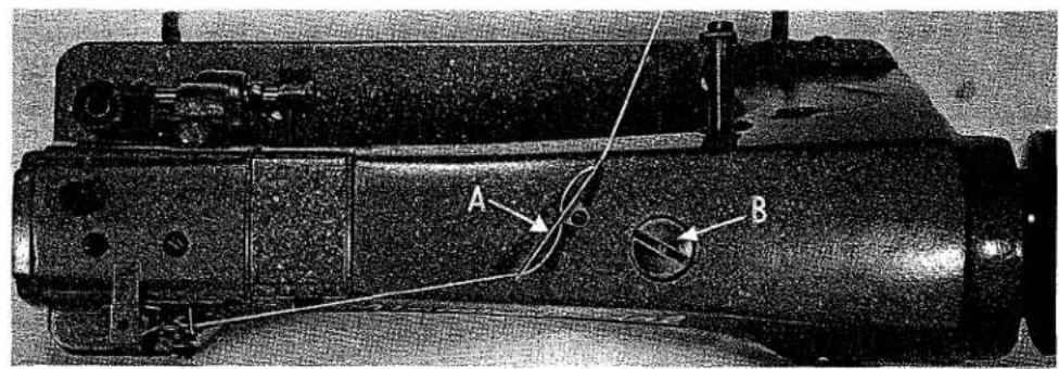
Fill main reservoir at plug screw (B, Fig. 2A) and check oil level at gauge (C); oil is at maximum level when needle is in yellow band marked "FULL". Oil should be added when needle is in yellow band marked "LOW". Use a stainless water-white straight mineral oil of a Saybolt viscosity of 90 to 125 seconds at 100^ Fahrenheit in the main reservoir. This is equivalent to Union Special specification No. 175.
Oil may be drained from main reservoir by removing plug screw (D, Fig. 2A).
The quantity of oil supplied to the hook is controlled by dial (E). Turning the dial in the direction of the arrow (counterclockwise) increases the oil flow and in a clockwise direction decreases the flow of oil.
NOTE: The top roller drive mechanism must be manually oiled at four points; this must be accomplished daily, preferably at the start each morning. The four points are as follows:
text_image
Technical diagram of a mechanical device with labeled components A and B, showing internal structure and wiring.
natural_image
Top-down view of a mechanical component with a circular feature and internal structure (no visible text or symbols)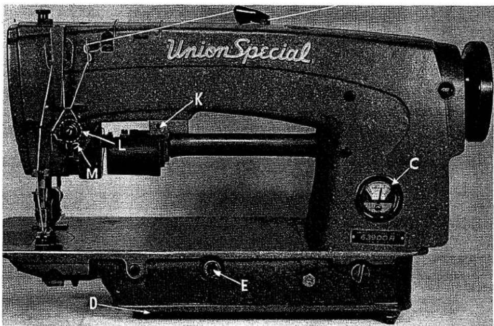
text_image
UnionSpecial K L M C 6.3900A D EWRAP THREAD AROUND ROTARY DISK (L) TWO COMPLETE TURNS ... THEN THREAD TENSION POST EYELET (M).
text_image
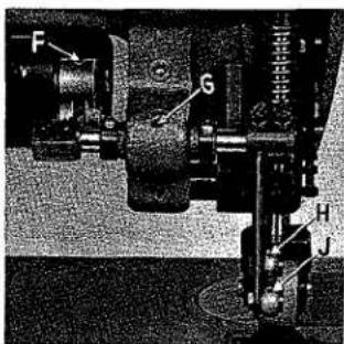
F G H JFig. 2A
OILING (Continued)
It is recommended that a new machine, or one that has been out of service for a long period, be lubricated by removing the head cover and oiling all the moving parts. After oiling, replace head cover as no further hand oiling will be required. Run machine slowly for several minutes to distribute oil to the various parts. Full speed operation can then be expected without damage.
INSTRUCTIONS FOR MECHANICS
The adjusting instructions for Styles 63900 R and S are the same as for Styles 63900 C and D respectively with the following exceptions and additions. The instructions that are different from those covered in Catalog No. 126 M (Second Edition), the headings will indicate the page it can be found in that catalog.
PRESSER BAR CONNECTION (Page 29)
The presser bar connection (A, Fig. 16B) should be set so that it is approximately 1/32 inch above the lower presser bar bushing (B, Fig. 16B). This is accomplished by tipping the machine back against the rest pin, loosening the lock nut (A, Fig. 15 - Cat. No. 126 M) and relocating the stop screw (B) on the lifter lever bell crank (C). By turning the stop screw to the right or left, the proper setting of the presser bar connection is accomplished. Tighten the lock nut (A) to lock the stop screw in place.
PRESSER BAR GUIDE (Page 29)
When locating the presser bar guide (C, Fig. 16B) the presser foot must rest directly against the throat plate with the feed dog in its lowest position. The guide is set properly when there is a 1/16 inch space between the bottom of the presser bar guide (C) and the top of presser bar connection (A, Fig. 16B).
To obtain this setting, remove the pressure from the presser spring (D) and loosen set screw (E). Tap on the presser foot to insure its being down on the throat plate. Set the guide to the 1/16 inch dimension, center the foot by turning it so that the needle enters the middle of the needle slot. Retighten screw (E) in guide and apply pressure to the presser foot by turning the presser spring regulator (F) clockwise.
Set the needle thread pull-up bracket (G, Fig. 16B), so that the underside of the bracket is 4 5/8 inches above the throat plate (Fig. 16B).
ADDITIONAL ADJUSTING INSTRUCTIONS FOR STYLES 63900 R and S
The feed dog should be set to the desired number of stitches per inch with the puller (top roller) disengaged. After this is accomplished, engage the puller.
The puller is timed so that it has completed its travel before the point of the needle enters the thickest part of the material being sewn. Synchronization of the puller with the feed dog is of the utmost importance. The puller should begin feeding at the same time the feed dog begins its feeding cycle.

text_image
Technical diagram of a mechanical device with labeled parts and dimensionsFig. 16B
ADDITIONAL ADJUSTING INSTRUCTIONS FOR STYLES 63900 R and S (Continued)
If this is not so, turn the handwheel in the operating direction to a point where the puller roller starts to revolve. Loosen the two set screws holding the puller drive shaft head (A, Fig. 29), hold the puller drive shaft head in place and turn the handwheel until the tips of the feed dog teeth are flush with the top of the throat plate at the beginning of the feeding cycle. Retighten set screws, making sure that all end play is removed from the puller drive shaft.
The puller should continue feeding until the feed dog has completed its feeding cycle and both should stop feeding at the same time. It should not allow material build up between the presser foot and puller when running at slow or high speeds. The material should be kept taut at all times. The puller should not feed faster than the feed dog.

text_image
Technical diagram of a mechanical device with labeled components A, B, and CFig. 29
This adjustment is accomplished by loosening lock nut (B, Fig. 29) (it has a left hand thread) on the end of the puller regulating stud. Turn screw (C) clockwise to decrease the puller roller travel or counterclockwise to increase the puller roller travel. Retighten lock nut (B).
Make sure there is enough pressure on the material going under the puller roller. The puller should cross over seams uniformly, but be sure there is enough pressure to insure good feeding.
Turning the regulator (H, Fig. 16B) clockwise increases the pressure and counterclockwise acts the reverse. Locking nut (J) is provided to maintain this setting.
EXPLODED VIEWS
AND
DESCRIPTION OF PARTS
FOR
63900 NEEDLE FEED
LOCKSTITCH MACHINES
WITH
text_image
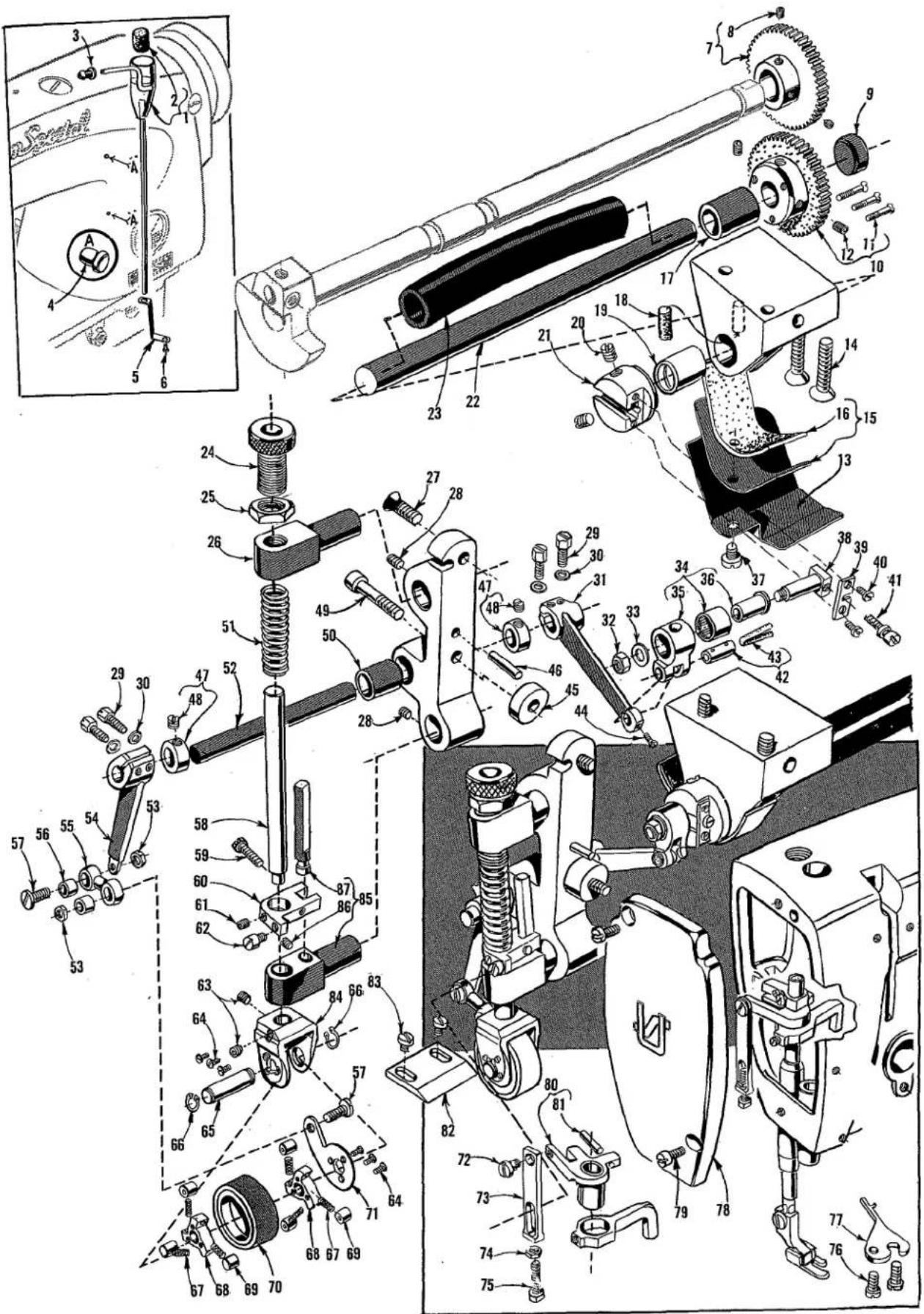
Technical diagram of a mechanical assembly with numbered parts and exploded view, likely for assembly or maintenance purposes.TOP DRIVEN ROLLER FEED MECHANISM AND MISCELLANEOUS PARTS
| Ref.No. | PartNo. | Description | Amt.Req. |
| 1 | 63494 D | Head Oil Siphon Assembly---- | 1 |
| 2 | 666-237 | Felt Plug---- | 1 |
| 3 | 61494 N | Retaining Grommet---- | 1 |
| 4 | 63494 B | Plug, plastic, for arm---- | 2 |
| 5 | 63494 | Siphon Primer Position Bracket---- | 1 |
| 6 | 22564 | Screw---- | 1 |
| 7 | 63439 U | Puller Driving Gear---- | 1 |
| 8 | 22651 CD-3 | Set Screw---- | 2 |
| 9 | 63493 A | Bed Plug---- | 1 |
| 10 | 63439 V | Puller Driven Gear---- | 1 |
| 11 | 22525 C | Screw---- | 3 |
| 12 | 22894 J | Set Screw---- | 2 |
| 13 | 63939 M | Guard, for roller drive shaft---- | 1 |
| 14 | 22657 E-16 | Screw, for roller drive shaft bracket---- | 2 |
| 15 | 63979 A | Oil Shield, for roller drive shaft bushing---- | 1 |
| 16 | 666-244 | Felt Lining---- | 1 |
| 17 | 63479 C | Roller Drive Shaft Bushing, right---- | 1 |
| 18 | 666-164 | Felt Oil Wick, for roller drive shaft---- | 1 |
| 19 | 63479 D | Roller Drive Shaft Bushing, left---- | 1 |
| 20 | 22591 | Screw, for roller drive shaft head---- | 2 |
| 21 | 63439 R | Roller Drive Shaft Head---- | 1 |
| 22 | 63439 Y | Roller Drive Shaft---- | 1 |
| 23 | 63479 A | Roller Drive Shaft Sleeve---- | 1 |
| 24 | 54277 C | Presser Spring Adjusting Screw---- | 1 |
| 25 | 35733 G | Locknut---- | 1 |
| 26 | 63439 L | Upper Puller Roller Guide---- | 1 |
| 27 | 22656 D-12 | Screw, for puller mechanism main support---- | 1 |
| 28 | 22894 C | Set Screw, for puller roller guides---- | 2 |
| 29 | 22519 C | Screw, for feed rocker arm and clutch puller rocker arm---- | 4 |
| 30 | 51235 G | Washer, for feed rocker arm and clutch puller rocker arm---- | 4 |
| 31 | 51235 A | Feed Rocker Arm---- | 1 |
| 32 | 269 | Nut, for feed crank stud---- | 1 |
| 33 | 20 | Washer, for feed crank stud---- | 1 |
| 34 | 63439 AE | Feed Crank Link Assembly---- | 1 |
| 35 | 51236 D | Feed Crank Link---- | 1 |
| 36 | 63439 AD | Ferrule---- | 1 |
| 37 | 25 S | Screw, for oil shield and guard---- | 1 |
| 38 | 51236 G | Feed Crank Stud---- | 1 |
| 39 | 51236 B | Feed Crank Stud Cap---- | 1 |
| 40 | 22768 | Screw, for feed crank stud cap---- | 2 |
| 41 | 82 | Adjusting Screw, for feed crank stud---- | 1 |
| 42 | 51054 | Feed Link Crank Pin---- | 1 |
| 43 | 666-149 | Felt Wick---- | 1 |
| 44 | 77 | Screw, for feed rocker arm---- | 1 |
| 45 to 89 | See following page | ||
text_image
Technical diagram of a mechanical assembly with numbered parts and exploded view, likely for assembly or maintenance purposes.TOP DRIVEN ROLLER FEED MECHANISM AND MISCELLANEOUS PARTS
| Ref.No. | PartNo. | Description | Amt.Req. |
| 1 to 44 | See the preceding page | ||
| 45 | 63439 W | Spacer, for puller mechanism main support | 1 |
| 46 | 53564 G | Dowel Pin, for puller mechanism main support | 1 |
| 47 | 482 | Collar, for puller rocker arm shaft | 2 |
| 48 | 98 | Screw | 1 |
| 49 | 22652 D-20 | Screw, for puller mechanism main support | 1 |
| 50 | 63439 F | Bushing, for puller mechanism main support | 1 |
| 51 | 54277 B | Presser Spring, for puller roller | 1 |
| 52 | 63439 E | Puller Rocker Arm Shaft | 1 |
| 53 | 12934 A | Nut, for drive link screw | 2 |
| 54 | 63439 D | Clutch Puller Rocker Arm | 1 |
| 55 | 51770-56 | Drive Link | 1 |
| 56 | 51771 | Ferrule, for drive link | 2 |
| 57 | 22757 | Screw, for drive link | 2 |
| 58 | 54277 J | Presser Bar, for puller roller | 1 |
| 59 | T38 | Screw, for roller presser bar and lifter | 1 |
| 60 | 63439 S | Roller Presser Bar and Lifter | 1 |
| 61 | 22894 P | Set Screw, for roller presser bar and lifter | 1 |
| 62 | 22892 A | Screw, for roller lifter link | 1 |
| 63 | 22894 C | Screw, for upper roller and puller clutch bracket | 2 |
| 64 | 605 A | Screw, for feed clutch disc | 6 |
| 65 | 63439 J | Upper Puller Roller Shaft | 1 |
| 66 | 660-208 | Truarc Ring, for upper puller roller shaft | 2 |
| 67 | 54274 M | Clutch Roller Spring | 6 |
| 68 | 63439 M | Feed Clutch Disc | 2 |
| 69 | 63439 N | Clutch Roller | 6 |
| 70 | 63439 Z | Feed Roller, rubber | 1 |
| * | 63439 H | Feed Roller, steel tooth (not shown) | 1 |
| 71 | 63439 P | Clutch Driving Lever | 1 |
| 72 | 86 | Screw, for roller lifter link | 1 |
| 73 | 63439 AK | Roller Lifter Link | 1 |
| 74 | 907 | Nut, for roller lifter link screw | 1 |
| 75 | 99245 | Screw, for roller lifter link | 1 |
| 76 | 93 | Screw, for bobbin case holder positioning finger | 1 |
| 77 | 61414 A | Bobbin Case Holder Positioning Finger | 1 |
| 78 | 63982 G | Head Cover | 1 |
| 79 | 22516 | Screw, for head cover | 2 |
| 80 | 63458 E | Tension Release Bushing and Guide | 1 |
| 81 | 660-219 B | Roll Pin | 1 |
| 82 | 61439 P | Feed Plate, for top feed roller | 1 |
| 83 | 376 | Screw, for feed plate | 2 |
| 84 | 63439 C | Upper Roller and Puller Clutch Bracket | 1 |
| 85 | 63439 K | Lower Puller Roller Guide | 1 |
| 86 | 22894 C | Screw | 1 |
| 87 | 63439 AF | Guide Bar | 1 |
* Available as an extra send and charge item only.
SALES OFFICES AND REPRESENTATIVES
†Handle Union Special and Columbia only.
‡Handle Lewis and Columbia only.
All others handle Union Special, Lewis and Columbia with certain exceptions.
UNITED STATES
ALABAMA 35206, BIRMINGHAM, 732-84th Street, South, Lloyd D. Baldwin, Tel. 833-9904.
ALABAMA 36107, MONTGOMERY, 3223 Willow Lane Dr., (Zip Code 36110), Tommy Hendrix, Tel. 272-6667.
ARKANSAS 72203, LITTLE ROCK, P.O. Box 1783, James T. Taylor, Tel. (501) 376-3121.
*CALIFORNIA 90021, LOS ANGELES, 1100 E. Pico Blvd., Paul M. Mason, Mgr., Tel. Madison 5-5828.
CALIFORNIA 94110, SAN FRANCISCO, 3420-25th Street Robert J. Vall, Tel. 415/826-5969.
\$CALIFORNIA 94103, SAN FRANCISCO, Apparel City Sewing Machine Co., 1155 Mission St., Tel. Market 1-6660.
COLORADO 80002, ARVADA, Casey's Sewing Machine Service, 5719 Reed St., Tel. 424-6630.
CONNECTICUT 06811, DANBURY, 22 Bairnum Road, Robert W. Gaines, Tel. 746-3652.
FLORIDA 33127, MIAMI, 2525 N.W. 2nd Ave., Trimco Sewing Equipment, Inc., Tel. 633-1138.
FLORIDA 33566, PLANT CITY, 506 N. Gordon St. James C. Morgan, Tel. 752-1829.
*GEORGIA 30324, ATLANTA, 2120 Plasters Bridge Road, N.E., Merritt M. Ambrose, Mgr., Tel. 875-9237.
GEORGIA 30529, COMMERCE, Lakeview Drive, J. Tom Hanley, Tel. 335-4061.
GEORGIA 30030, DECATUR, 1713 Coventry Road, Joe V. Parker, Tel. 377-5559.
GEORGIA 31021, DUBLIN, 1615 Knox St., John W. Jones, Tel. 272-4663.
GEORGIA 30501, GAINESVILLE, RFD #1, John Bradberry, Tel. Cumming, Ga. 887-4732.
GEORGIA 30680, WINDER, 508 Fifth Ave., B. D. Smith, Tel. 867-3208.
★ILLINOIS 60610, CHICAGO, 400 N. Franklin St., Fred L. Koehler, Mgr., Tel. 644-6920.
KANSAS 66208, KANSAS CITY (PRAIRIE VILLAGE) 7351 Rosewood, Cleo C. Smith, Tel. HE 2-1705.
KENTUCKY 40207, LOUISVILLE, P.O. Box 7261, Raymond E. Hinton, Tel. 587-0042.
LOUISIANA 70458, NEW ORLEANS (SLIDELL) 275 Palm Springs Drive, Duane Bunger, Tel. 504/643-2484.
MARYLAND 21215, BALTIMORE, P.O. Box 2505, Ralph B. Foster, Tel. 727-8499.
\$MARYLAND 21204, BALTIMORE, J. Dashew, Inc., 417 W. Baltimore St., Tel. LExington 9-1838.
★MASSACHUSETTS 02111, BOSTON, 179 Lincoln St., William E. Palm, Mgr., Tel. Liberty 2-0147.
MASSACHUSETTS 02021, CANTON, York St., RFD, Roy T. Pedersen, Tel. 828-1412.
MASSACHUSETTS 02767, TAUNTON, P.O. Box #2 Raynham, Walter P. Godek, Tel. VanDyke 2-6149.
MICHIGAN 48223, DETROIT, 14561 Auburn, John Joyce, Tel. 313-584-4210.
MINNESOTA 55426, MINNEAPOLIS, 2800 Texas Ave., St. Louis Park, Minn., Leonard W. Koehler, Tel. 644-6236.
MISSISSIPPI 39209, JACKSON, 327 Eastview St., Jamie A. Boyette, Tel. Fleetwood 5-1976. Larry Lancaster, P.O. Box 1427 (Tupelo) 38801, Tel. 601/842-7650.
\$MISSOURI 64105, KANSAS CITY, Textile Machinery Co., 915 Broadway, Tel. Victor 2-9558.
MISSOURI 63114, ST LOUIS, 9022 Pallardy Lane, Carl E. McLaughlin, Tel. Chestnut 1-2368. 8725 Warner (Zip Code 63117), also Jerry Hicks.
†NEW HAMPSHIRE 03060, NASHUA, P.O. Box 257, Herman E. Haberman Jr., Tel. Tuxedo 2-9698.
†NEW JERSEY 07032, NORTH ARLINGTON, 32M Garden Terrace, Joseph Loglisci, Tel. 991-8211.
†NEW JERSEY 07010, RUTHERFORD, 246 Sylvan St., Richard W. Whitson, Tel. Geneva 8-2178.
NEW JERSEY 08091, WEST BERLIN, P.O. Box 26, Frank A. Noff, Tel. 767-4350.
NEW YORK 02110, LATHAM, 57 Sylvan Ave., Clarence A. Wheeler, Tel. 518-785-6371.
NEW YORK 14502, MACEDON, 3 Jupiter Way, James Holbohm, Tel. 986-4693.
★NEW YORK 10001, NEW YORK, 370 7th Ave., (Penn Terminal Bldg.), Clarence L. Rosenquist, Mgr., Tel. Chickering 4-8800.
NEW YORK 14609, ROCHESTER, A. J. Adams Co., 1051 Culvar Rd., Tel. BUTTER 8-7250.
NEW YORK 11553, UNIONDALE, 873 Henry St., Anthony Candell, Tel. Ivanhoe 3-7477.
NORTH CAROLINA 27403, GREENSBORO, P.O. Box 226, William D. Harrod, Tel. 299-9367. 4216 Pennydale Dr., (Zip Code 27407), also Harold E. Miller, Tel. 292-0734.
OHIO 44109, CLEVELAND, 4914 Pearl Road, Cut & Sew Equipment Co., Tel. 661-5901.
OHIO 43216, COLUMBUS, P.O. Box 874, Larry Kelsen, Tel. AXminister 1-1222.
OKLAHOMA 73119, OKLAHOMA CITY, 2226 Southwest 53rd St., G. B. Wiley, Tel. 685-2836.
OREGON, 97220, PORTLAND, 1950 N.E. 118th Ave. Robert E. Ritt. Phone: 503/771-2159 (Portland) 206/624-8083 (Seattle).
PENNSYLVANIA 18105, ALLENTOWN, P.O. Box 542, Luther: D. Cassell, Tel. 797-2111.
PENNSYLVANIA 18015, BETHLEHEM, 1212 Camac St., Ed Deogan, Tel. 868-8204.
PENNSYLVANIA 18003, BERWICK, 1013 E. 16th St., Donald McFadden, Tel. 752-2442.
PENNSYLVANIA 18411, CLARKS SUMMIT, 428 West Grove Ave., John J. Laffer, Tel. JUniper 7-2820.
★PENNSYLVANIA 19124, PHILADELPHIA, 4234 Macalester Ave., Ben W. Merz, Mgr., Tel. Gladstone 5-9800.
†PENNSYLVANIA 15670, NEW ALEXANDRIA, (Pittsburgh), R.D. No. 1, Box 26A, W. Dale Speer, Tel. (Pittsburgh) 563-3589, also R. N. Bates.
PENNSYLVANIA 17567, REAMSTOWN, P.O. Box 176, David M. Bender, Tel. 267-6109, also F. J. Bartosic.
PENNSYLVANIA 17404, YORK, P.O. Box 884, Harding T. Powell, 854-8040, also F. J. Bartoslc.
SOUTH CAROLINA 29204, COLUMBIA, P.O. Box 4246, Virlyn R. Crisler, Tel. Sunset 7-0863. P.O. Box 4112, also J. W. Carter, Tel. 254-4255.
SOUTH CAROLINA 29607, GREENVILLE, 25 Sir Abbot St., Orville W. Gregory, Tel. Cedar 9-5539.
TENNESSEE, 37421, CHATTANOOGA, 1711 Ray Jo Circle, John W. Carter 615-892-1489.
TENNESSEE 37919, KNOXVILLE, 3905 Greenleaf Ave., Horace E. Clinard, Tel. 588-1865.
TENNESSEE 38117, MEMPHIS, 4695 Dunn Rd., Richard J. Lindhorst, Tel. Mutual 5-6750.
TENNESSEE 37214, NASHVILLE, 2517 Woodberry Drive, Felix M. Blunkall, Tel. 615-254-7538.
★TEXAS 75247, DALLAS, 6718 Oakbrook Blvd., P.O. Box 47424, J. H. Muir Mgr., Tel. 214/637-5990.
TEXAS 79926, EL PASO, P.O. Box 9573, Edward E. Smith, Tel. 598-2928.
TEXAS 76106, FT. WORTH, 1201 Altamont Dr., Arnold Stier-walt, Tel. 626-3183.
TEXAS 78213, SAN ANTONIO, Jerry Gregory, P.O. Box 13126, Tel. DI 2-5924.
UTAH 84105, SALT LAKE CITY, 1215 E. 13th South St., Larry F. Rosvall, Tel. IN 7-6931.
VIRGINIA 24006, Roanoke, P.O. Box 1151, Tom Traylor, Tel. 703-342-3233, also P. C. Eble.
CANADA
UNION SPECIAL MACHINE Co. of Canada, Ltd.
BRITISH COLUMBIA, N. BURNABY 2, James Murray, 1522 Madison Ave., Tel. MU 3-3917.
MANITOBA, WINNIPEG 2, Frank Thierman, Rm. 201, Whittle Bldg., 70 Arthur St., Tel. 204-943-4933.
★ONTARIO, TORONTO 2B, Peter Fowler, Mgr.-Rep., 355 King St. West, Tel. Empire 6-2939.
★QUEBEC, MONTREAL 11, John Caschetto, Mgr.-Rep., 9595 Charles de Lolour St. Tel. 514/387-7191.

natural_image
Black-and-white world map of the Americas and surrounding oceans, showing continents and latitude/longitude lines (no text labels)WORLDWIDE SALES AND SERVICE
Union Special Corporation maintains sales and service facilities throughout the world. These offices will aid you in the selection of the right sewing equipment for your particular operation. Union Special Corporation representatives and service technicians are factory trained and are able to serve your needs promptly and efficiently. Whatever your location, there is a qualified representative to serve you.
Corporate Office:
One Union Special Plaza
Huntley, IL 60142
Phone: 708·669·5101
Fax: 708·669·1096
European Distribution Center:
Union Special GmbH
Raiffeisenstrasse 3
D-71696 Möglingen, Germany
Tel: 49·07141·247·0
Fax: 49·7141·247·100
Brussels, Belgium
Charlotte, N.C.
Commerce, CA
El Paso, TX
Hong Kong, China
HunHey, IL
Leicester, England
Lille, France
Miami, FL
Milan, Italy
Mission, TX
Möglingen, Germany
Montreal, Quebec
Osaka, Japan
Other Representatives throughout all parts of the world.

Finest Quality
Union Special® INDUSTRIAL SEWING EQUIPMENT