63900AAE - Sewing machine Union Special - Free user manual and instructions
Find the device manual for free 63900AAE Union Special in PDF.

User questions about 63900AAE Union Special
0 question about this device. Answer the ones you know or ask your own.
Ask a new question about this device
Download the instructions for your Sewing machine in PDF format for free! Find your manual 63900AAE - Union Special and take your electronic device back in hand. On this page are published all the documents necessary for the use of your device. 63900AAE by Union Special.
USER MANUAL 63900AAE Union Special
ADJUSTING INSTRUCTIONS / ILLUSTRATED PARTS LIST

natural_image
White JUKI Union Special sewing machine with needle and control panel (no visible text or symbols on body)63900 STREAMLINED
HIGH SPEED NEEDLE FEED
TOP AND BOTTOM ROLLER FEED
LOCKSTITCH MACHINES
MANUAL NO. PT9636
STYLES
63900AM
63900AML
63900AT
63900AW
63900AAE
CONTENTS
•PREFACE 4
•SAFETYRULES 5
• IDENTIFICATION OF MACHINES 6
•CLASS DESCRIPTION 6
•STYLEOFMACHINES 6
•ILLUSTRATIONS 6
•ILLUSTRATIONS(CONT.) 7
• IDENTIFYING PARTS 7
-NEEDLES 7
•TABLEBOARD 8
•BOBBIN WINDER 8
•BELTS 8
•LUBRICATION....9
•RECOMMENDED OIL 9
•OIL GAUGE 9
•SELF-PRIMING HEAD OIL SIPHON 10
•INSTALLING AND MAINTENANCE OF OIL SIPHON 10
•THREAD 11
•REMOVING THE BOBBIN CASE 11
•WINDING THE BOBBIN 11
•THREADING THE BOBBIN CASE 11
•THREADING THE BOBBIN CASE (CONT.) 12
• REPLACING THE BOBBIN CASE 12
•INSERTING THE NEEDLE 12
•THREADING THE NEEDLE 12
•PREPARATION FOR SEWING 12
•TENSIONS 12
•BOBBIN THREAD TENSION 12
•BOBBIN THREAD TENSION(CONT.) 13
-NEEDLE THREAD TENSION 13
•CHANGING THE STITCH LENGTH 13
•TIMING THE NEEDLE FEED WITH THE CONTINUOUS TURNING ROLLER FEED 14
•PRESSUREONMATERIAL 14
- SETTING THE NEEDLE BARTOHEIGHT 14
CONTENTS(CONT.)
•TIMING THE HOOK 15
-NEEDLEGUARDINSTRUCTIONS 15
-NEEDLE GUARD INSTRUCTIONS (CONT.) 16
•HOOK LUBRICATION 16
•PRESSERBARGUIDE 16
•PRESER BAR CONNECTION 16
•TENSIONASSEMBLYADJUSTMENT 17
• TENSIONRELEASE 17
• THREAD CONTROL 17
• THREAD CONTROL (CONT.) 18
•BOTTOM COVER 18
•HOOK SHAFT 18
•HOOK SHAFT (CONT.) 19
•REMOVAL OF OILING DEVICE 19
- REASSEMBLY OF OILING DEVICE 20
- REASSEMBLY OF OILING DEVICE (CONT.) 21
•UPPER MAIN SHAFT 21
•UPPER MAIN SHAFT (CONT.) 22
•HANDWHEEL 22
•HANDWHEEL (CONT.) 23
•ATTACHMENTS 23
-NEEDLEHOLE INSERT 23
•MAINFRAME, BUSHING, OIL GAUGE HEAD OIL SIPHON AND MISCELLANEOUS OILING PARTS 25
•MAINFRAME, BUSHING, OIL GAUGE HEAD OIL SIPHON AND MISCELLANEOUS OILING PARTS (CONT.) ..... 27
•MAIN FRAME MISCELLANEOUS COVERS AND NEEDLE TENSION PARTS 29
•MAIN FRAME MISCELLANEOUS COVERS AND NEEDLE TENSION PARTS (CONT.) 31
•MAIN AND HOOK DRIVE SHAFTS, NEEDLE BAR AND FOOT LIFTER MECHANISM 33
-NEEDLE FEED DRIVING PARTS 35
•PRESSER FEET, PRESSER BAR, TOP FEED ROLLER MECHANISM AND ATTACHMENTS ...... 37
•PRESSER FEET, PRESSER BAR, TOP FEED ROLLER MECHANISM AND ATTACHMENTS 39
- ROTATING HOOK ASSEMBLY AND HOOK OILING PARTS 41
First Edition Copyright 1997
By
Union Special Corporation Rights Reserved In All Countries
Printed in U.S.A. October 1997
PREFACE
This parts manual has been prepared to assist you in locating individual parts or assemblies on 63900 Series machines.
It is the desire of Union Special that each machine run at its optimum performance. Parts listed in this manual are designed specifically for your machine and are manufactured with utmost precision to assure long lasting service.
This manual has been comprised on the basis of available information. Changes in design and/or improvements may incorporate a slight modification of configuration in illustrations or part numbers.
On the following pages are illustrations and terminology used in describing the parts used on 63900 Series machines.
SAFETYRULES
- Before putting the machines described in this manual into service, carefully read the instructions. The starting of each machine is only permitted after taking notice of the instructions and by qualified operators.
IMPORTANT! Before putting the machine into service, also read the safety rules and instructions from the motor supplier.
-
Observe the national safety rules valid for your country.
-
The sewing machines described in this instruction manual are prohibited from being put into service until it has been ascertained that the sewing units which these sewing machines will be built into, have conformed with the EC Council Directives (89/392/EEC, Annex II B).
Each machine is only allowed to be used as foreseen. The foreseen use of the particular machine is described in paragraph "STYLES OF MACHINES" of this instruction manual. Another use, going beyond the description, is not as foreseen.
-
All safety devices must be in position when the machine is ready for work or in operation. Operation of the machine without the appertaining safety devices is prohibited.
-
Wear safety glasses.
-
In case of machine conversions and changes all valid safety rules must be considered. Conversions and changes are made at your own risk.
-
The warning hints in the instructions are marked with one of these two symbols:

- When doing the following the machine has to be disconnected from the power supply by turning off the main switch or by pulling out the main plug:
8.1 When threading needle(s), looper, spreader etc.
8.2 When replacing any parts such as needle(s), presser foot, throat plate, looper, spreader, feed dog, needle guard, folder, fabric guide etc.
8.3 When leaving the workplace and when the workplace is unattended.
8.4 When doing maintenance work.
8.5 When using clutch motors without actuation lock, wait until the motor is stopped totally.
-
Maintenance, repair and conversion work (see item 8) must be done only by trained technicians or special skilled personnel under consideration of the instructions.
-
Any work on the electrical equipment must be done by an electrician or under direction and supervision of special skilled personnel.
- Work on parts and equipment under electrical power is not permitted. Permissible exceptions are described in the applicable sections of standard sheet DIN VDE 0105.
- Before doing maintenance and repair work on the pneumatic equipment, the machine has to be disconnected from the compressed air supply. In case of existing residual air pressure, after disconnecting from compressed air supply (i.e. pneumatic equipment with air tank), the pressure has to be removed by bleeding.

IDENTIFICATION OF MACHINES
Each UNION SPECIAL machine is identified by a style number, which is stamped into the style plate affixed to the middle of the machine under the tension assembly. The serial number is stamped into the serial number plate affixed to the right rear base of the machine.
CLASS DESCRIPTION
High speed streamlined long arm needle feed lockstitch machines. one needle, light, medium and heavy duty, continuous running roller feed, rotary hook, horizontal hook shaft, gears for changing stitch length, slot segment for adjusting needle feed, 1 1/4 inch needle bar travel, one reservoir enclosed automatic lubrication system, head oil siphon, adjustable hook oil control, needle bearing for take-up lever and needle bar driving link, needle feed timing on upper shaft, maximum work space to right of needle bar 8 inches.
STYLE OF MACHINES
63900AM For making 3/8 on 1/2 inch turned down hem on legs of overalls, coveralls, and dungarees. Seam Specification 301-EFb-1 inverted, Specify size of hem. Maximum recommended speed 5200 R.P.M.
63900AML Same as 63900AM except includes a hook with 52% greater bobbin capacity to reduce frequency of bobbin changes.
63900AT For making a 1/2 or 2 1/2 inch hem turned by hand on children's wear, men's dress pants, semi-dress pants and work pants. Sewn when garment reaches machine inside out. Seam Specification 301EFb-1 or EFa-1. Maximum recommended speed 5200 R.P.M.
63900AW For top stitching waistbands on twill and woolen pants. Machine equipped to sew over belt loops. Fitted with cloth plate extension. Seam Specification 301-SSa-1. Maximum recommended speed 5200 R.P.M.
63900AAE Same as Style 63900AW, except fitted with spring guide keel on presser foot in line with centerline of needle hole.
ILLUSTRATIONS
This manual has been arranged to simplify ordering repair parts. Exploded views of various sections of the mechanism are shown so that the parts may be seen in their actual position in the machine. On the page opposite the illustration will be found a listing of the parts with their part numbers, description and the number of pieces required in the particular view being shown.
Numbers in the first column are reference numbers only, and merely indicate the position of the part in the illustration. The reference number should never be used in ordering parts. Always use the part number listed in the second column.
Component parts of sub-assemblies which can be furnished for repairs are indicated by indenting their descriptions under the description of the main sub-assembly. As an example refer to the following text.
-
29126EL Needle Feed Driving Eccentric and Connecting Rod Assembly 1
-
22894J Set Screw 2
ILLUSTRATIONS (CONT.)
When a part is common to all machines covered in this manual, no specific usage will be mentioned in the description. However, when the parts for the various machines are not the same, the specific usage will be mentioned in the description and, if necessary, the difference will be shown in the illustration.
*Ref. No. showing no Part No. is for location only. Part is not for sale separately.
A numerical index of all the parts shown in this manual is located at the back. This will facilitate locating the illustration and description when only a part number is known.
IDENTIFYING PARTS
Where construction permits, each part is stamped with its part number. On some of the smaller parts and on those where construction does not permit, an identification letter is stamped in to distinguish the part from similar ones.
PLEASE NOTE: Part numbers represent the same part, regardless of which manual they appear. On all orders please include part number, name and style of machine for which the part was ordered.
For optimum performance use only genuine Union Special replacement parts.
NEEDLES
Each needle has both a type and size number. The type number denotes the kind of shank, point, length, groove, finish and other details. The size number, stamped on the needle shank, denotes the largest diameter of the blade measured between the shank and the eye. Collectively, the type number and size number represent the complete symbol which is given on the label of all needles packed and sold by Union Special.
TYPE DESCRIPTION
180 GYS Round shank, round point, lockstitch, short length ball eye single groove, struck groove, deep spot, chromium plated - sizes 075/029, 080/032, 090/036, 100/040, 125/049, 140, 054, 150/060.
180 GWS Round shank, round point, lockstitch, short length, oversize ball eye, single groove, struck groove, deep spot, chromium plated - sizes 090/036, 100/040, 110/044, 125/049, 140/054.
When changing the needle, make sure it is fully inserted in the needle holder before the screw is tightened.
When ordering needles, please use the complete type and size numbers as printed on the package to ensure prompt and accurate processing of your order. A complete order should read as follows: "100 needles, type 130 GS, size 125/049".
TABLEBOARD
The tableboard can now be mounted on the pedestal using four screws, adjusting the nuts so the top of the tableboard is flush with the top of the machine bed plate.
BOBBIN WINDER
The bobbin winder should be secured to the table top so that its pulley will be located directly in front of the sewing machine belt and will bear against the belt when in operation. The base of the winder has two elongated attaching holes, which allow the mechanism to be moved closer to or farther away from the belt as needed. The pulley of the winder, when in operation, should exert only enough pressure against the belt to wind the bobbin. Regulation and operation of the bobbin winder is described under "Winding The Bobbin", under "Instructions For Operator's".
BELTS
These machines are equipped to use either #1 "Vee" or round belts.

text_image
A B JUKI Union Special
natural_image
Technical illustration of a JUKI sewing machine with labeled parts (no readable text beyond labels)Fig. 3
LUBRICATION
CAUTION! Oil has been drained from the main reservoir before shipment and the reservoir must be filled before starting to operate.
Lubricate machine thoroughly, in accordance with instructions which follow, and run slowly for several minutes to distribute the oil to the various parts. Full speed operation can then be expected without damage.
RECOMMENDED OIL
Use a stainless water-white straight mineral oil of a Saybolt viscosity of 90 to 125 seconds at 100^ Fahrenheit in the main reservoir. This is equivalent to Union special specification No. 175. Fill main reservoir at plug screw (B, Fig. 3) and check oil level at gauge (C): oil is at maximum level when needle is in yellow band marked "FULL". Oil should be added when needle is in yellow band marked "LOW".
It is recommended that a new machine, or one that has been out of service for an extended period, be lubricated as follows: Remove the head cover and directly oil the bearings of the needle bar link, the take-up and its lever and needle bar. Replace end cover, as no further hand oiling will be required.
Oil may be drained from main reservoir by removing plug screw (D, Fig. 3).
OIL GAUGE
The oil gauge is set at the factory to show the proper oil level in the reservoir. Should and adjustment become necessary, the following steps should be followed:
- Place the machine upright on a level table or bench.
- Remove the reservoir plug screw (located below the handwheel and near the bottom of the machine).
- Oil should be added or removed so that the oil level is approximately 1/8 inch below the bottom edge of the hole.
- Loosen lock nut (E, Fig. 3) on the calibrating screw (F), and turn screw left or right so the gauge needle rests on the yellow band marked "FULL" on gauge (C).
- Tighten lock nut and replace plug screw.
SELF-PRIMING HEAD OIL SIPHON
Class 63900 machines are equipped with a self-priming head oil siphon. When the machine is started, oil splashes on the priming cup felt, filters through the felt and trickles down the vertical oil tube, thus priming the siphon. Once the prime is established, it is maintained, unless the felt is removed. The siphon operates twenty-four hours a day, removing oil at the rate of six to twelve drops per minute, which, of course, far exceeds the rate at which oil collects in the head.

text_image
63494M Oil Tube 61494N Retaining Grommet 63994 Intake Tube 61494L Screw 666-237 Priming Cup Felt 666-214 Intake Felt 56393AA Oil Tube (2) 63994 Oil Siphon 63993G Oil Siphon TubeINSTALLING AND MAINTENANCE OF OIL SIPHON
A newly installed siphon starts its action within three to five minutes after the machine is operating. However, it may be twenty minutes or so before all the air is removed from the line and the siphon is in full operation. Within an hour, there should be a distinct reduction of the oil in the head sump. If the siphon does not function, determine if the siphon intake tube, located in the head, is inserted in the felt block and that the plastic tube is connected at both ends. If the above two items do not correct the siphon, replace the siphon felts as described below.
The felt in the priming cup is designed for a specific purpose. This felt, No. 666-237, is to meter the flow of priming oil and to prevent the entrance of air. The felt also acts as a filter and keeps the siphon clear of lint.
If the priming cup felt and the intake felt (666-214) becomes contaminated with an excessive amount of lint, it may be necessary to replace the felts. The priming cup felt is replaced by removing access plug at back of machine and replacing felt 666-237. For the best initial self-priming condition, the felt of the siphon should be installed dry. The intake felt is replaced by removing the end cover.
However, if for some reason the priming cup felt has been oiled before installing, the siphon may fail because air is trapped in the felt. As a precaution, remove felt from cup. Then, while squeezing the felt between the fingers, saturate it well with oil. In other words, squeeze out the air and replace it with oil. This prevents the trapping of air, and no trouble should be experienced when starting the siphon.
THREAD
While the direction of the twist in the bobbin thread is immaterial, the direction of the hook rotation favors the use of a left twist thread in the needle. To determine the direction of twist, grasp a short length of thread between thumb and forefinger of each hand. Turn the thread away from you with your right hand. If the strands unwind, it is a left twist, if not, it is a right twist.
REMOVING THE BOBBIN CASE
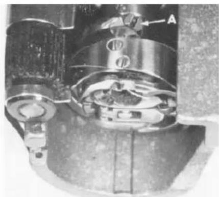
To remove the bobbin case, turn handwheel in operating direction until needle reaches its highest position. Using the left hand, reach in under the throat plate at left end of machine, open the bobbin case latch (A, Fig. 5), and pull the bobbin case out of the sewing hook.
Opening the latch retains the bobbin in the case. When the latch is closed, the bobbin is released and can readily be removed.
WINDING THE BOBBIN
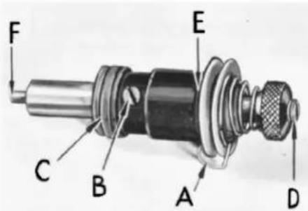
Thread the bobbin winder by leading the thread from the supply down through the eyelet (A, Fig. 6), down between the tension discs, and under the tension post. Press an empty bobbin on the winder shaft (B), up to the stop, wind the end of thread around the bobbin a few turns in a clockwise direction and press downwardly on hand lever (D) until pulley is moved into contact with machine belt, and is locked in that position. When the machine is operated, the bobbin will be rotated and filled until the thread engages the automatic throw-out member, which disengages the pulley. The extent to which the bobbin is filled can be varied by regulating the screw (C).
The tension post bracket is mounted on the winder base, and can be shifted from left to right by loosening screw (E) so that any tendency of the bobbin to wind unevenly may be readily corrected.
The purpose of the bobbin winder is to assure an operator of a full bobbin at all times. When the bobbin in the machine is used up, replace it with the full one, and begin to wind the empty on immediately. Bobbins can be rewound while the machine is sewing.
THREADING THE BOBBIN CASE
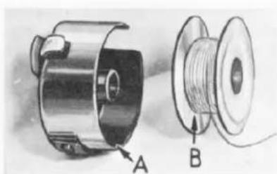
The bobbin case (A, Fig. 7) should be held between the thumb, forefinger and second finger of the LEFT hand.
The bobbin (B) itself should be held between the thumb and forefinger of the right hand with thread coming off the bottom of the bobbin.

natural_image
Close-up of a mechanical component with labeled point A (no readable text or symbols beyond label)Fig. 5

text_image
Technical diagram of a mechanical device with labeled parts A, B, C, D, and EFig. 6
natural_image
Technical illustration of a mechanical component with labeled parts A and B (no text or symbols beyond labels)Fig. 7
THREADING THE BOBBIN CASE (CONT.)
text_image
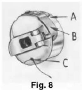
A B C Fig. 8Place the bobbin in the bobbin case. In one continuous motion, with thumb and forefinger of right hand, draw the bobbin thread through diagonal slot in bobbin case (A, Fig. 8) under the tension spring (B) and into self threading slot (C) on case. Mote direction of the rotation of the bobbin as the end of the thread is pulled when looking at the bobbin case from the back. The bobbin should rotate counterclockwise.
REPLACING THE BOBBIN CASE
Have the needle bar at its highest position, allow about two and one half inches of thread to hang free. The bobbin case latch should be opened with the left hand, and by reaching under the throat plate and through the bed plate extension, it should be placed part way into the sewing hook. the latch should then be released and bobbin case into position.
INSERTING THE NEEDLE

Insert the needle into the needle bar as far as it will go, with the spot (sometimes called scarf) towards the right, facing the handwheel. Tighten the nut securely.
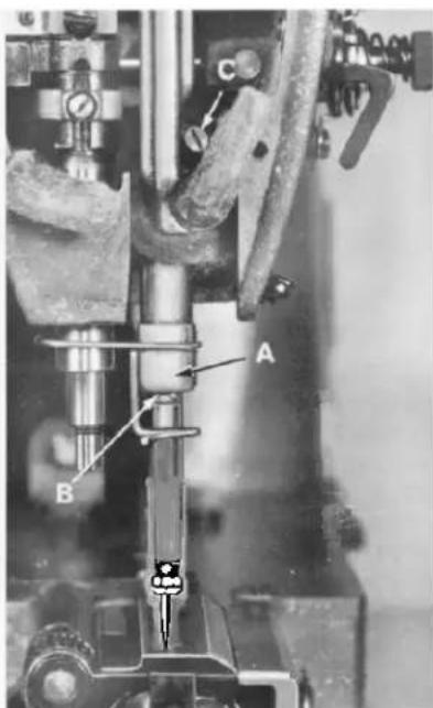
The cross hole in the needle bar, about 1/4 inch from the end (A, Fig. 9), is to show the operator when the needle has been inserted as far as it will go, and to provide a means for cleaning the accumulated lint from needle hole so the needle will seat properly.
THREADING THE NEEDLE
Fig. 9
Threading diagram (Fig. 3) shows the places where the needle thread passes. Please note that the needle thread passes through the needle eye from left to right.
PREPARATION FOR SEWING
With your left hand, hold the end of the needle thread, leaving it slack, and turn the handwheel in operating direction until the needle moves down and up again to its highest position. Pull up the needle thread and the bobbin thread will come up with it, through the needle hole in the throat plate. Draw both threads under the presser foot.
TENSIONS

natural_image
Diagram of a mechanical device with labeled parts A and B, showing rotational motion (no text or symbols beyond labels)Fig. 10
A perfect stitch is one in which the needle thread and bobbin thread are locked together in the center of the material being sewn. A stitch of this kind is secured by regulating the tensions on both threads.
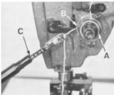
BOBBIN THREAD TENSION
The tension on the bobbin case is applied by means of a set screw (A, Fig. 10) which regulates the tension spring (B). The tension on the spring is correct when it is just sufficient to hold the bobbin case and bobbin suspended by the bobbin thread. The thread should not be in the eyelet for this adjustment check.
BOBBIN THREAD TENSION (CONT.)
Remove the bobbin case from its holder and turn set screw in spring in a clockwise direction to apply more tension or counterclockwise to release tension.
When the bobbin thread tension is correct, it rarely becomes necessary to make any changes as varying the needle thread tension will usually attain a good stitch.
NEEDLE THREAD TENSION
The needle thread tension is varied by turning the tension regulating nut (G, Fig. 3). Turning the nut in a clockwise direction increases the tension, while counterclockwise decreases it. This should not be done when the presser foot is in its raised position, but is generally done while the machine is sewing on a piece of scrap material.
CHANGING THE STITCH LENGTH
Unless otherwise specified machine Styles 63900AM, AML and AT will be equipped with upper feed regulator gear No. 63949-39 and lower feed regulator gear No. 63949-41 to produce 9 stitches per inch (S.P.I.), while Styles 63900AW, and AAE will be equipped with upper feed regulator gear No. 63949-37 and lower feed regulator gear No. 63949-43 to produce 10 S.P.I. Other gears are available and may be ordered separately. Refer to "Gear Chart" below for the gears necessary to produce S.P.I. other than previously described.

text_image
A C B DFig. 11
GEAR CHART
S.P.I. UPPER GEAR LOWER GEAR
6 63949-47 63949-33
7 63949-44 63949-36
8 63949-41 63949-39
9 63949-39 63949-41
10 63949-37 63949-43
11 63949-36 63949-44
12 63949-33 63949-47
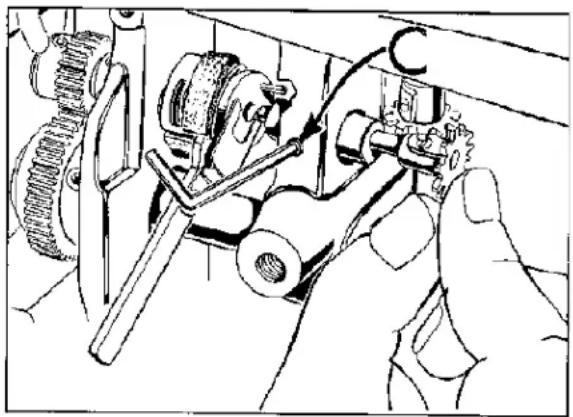
To remove feed regulators gears, first remove feed drive gear cover located under arm of machine. Now loosen screws (A and B Fig. 11) and slide gears (C and D) off their respective shafts. Replace with gears for desired stitch length. After new gears have been installed be sure to reset needle feed stitch length to agree with the continuous turning roller feed.
TIMING THE NEEDLE FEED WITH THE CONTINUOUS TURNING ROLLER FEED
text_image
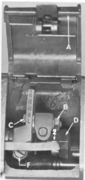
A B C D 2 FFig. 12
Open top cover (A, Fig. 12) in the head of the machine and loosen needle frame drive segment locking nut (B). Set connection stud (C) to point of maximum number of stitches per inch of needle feed. This would locate the connecting arm at letter "S".
Loosen two set screws on the needle frame drive eccentric (D). Rotate the handwheel until the needle bar is at the bottom of its stroke. Rotate the eccentric only, until the timing line (2) on the connecting arm and the eccentric hub coincide. Tighten all screws, on every thick seams that cause thread breakage advance needle feed timing slightly.
Rotate handwheel until the needle bar is at bottom of its stroke. The needle bar should be vertical. If it is not, loosen clamp screw (F) and move needle bar frame forward and backward until bar is vertical. Tighten screw, making sure allside play is removed from between the needle bar frame and the segment.
To set needle feed with roller feed loosen needle frame drive segment locking nut. Set connection toward higher designated letter on segment for approximate setting. Vary the needle travel so as to obtain the least amount of needle deflection when the needle enters or leaves the thickest section to be sewn.
PRESSURE ON MATERIAL
The presser spring (A, Fig. 17) should exert only enough pressure on the feed rollers to make the work feed uniformly. To increase the pressure on the preser foot, turn presser spring regulator (B, Fig. 17) in a clockwise direction.
Turning the regulator counterclockwise decreases the pressure.
text_image
Technical diagram of a machine tool with labeled parts A, B, and C, showing mechanical components and alignment indicators.Fig. 13
SETTING THE NEEDLE BAR TO HEIGHT
The three lines engraved on the needle bar are used in setting needle bar to height, and are referred to as TIMING LINES.
Th middle and lower lines are used for Styles 63900M, T, and W. For 63900AM, AML, AAE, AT and AW the upper and middle lines are used.
When the needle bar is at its lowest position the upper timing line (B, Fig. 13) should be EVEN with the lower edge of the lower needle bar frame (A).
To change the position of the needle bar, turn handwheel until the bar is at its lowest position. Then, loosen the clamp screw (C) and move the bar to the proper timing line. Keeping the needle bar line at its lowest position, tighten the screw securely.
TIMING THE HOOK
Remove throat plate. Loosen three set screws (A) in the hook, and hold the hook and the bobbin case holder in such a position as to prevent interference with the needle. Turn handwheel in operating direction until the needle bar is at its lowest position, and continue to turn the handwheel until the needle is ascending and the middle timing make (Fig. 13) used in setting the needle bar is even with the lower edge of the needle bar frame (A).
Turn the hook on the shaft until the point of the hook is even with the center of the needle and as close to the needle as possible without deflecting it. A spacing of .003 to .005 inch between the needle and the point of the hook is satisfactory. With the hook in this position, tighten the set screw opposite the hook point securely. Then, tighten the two remaining screws securely, and recheck the timing of the hook with the needle. At the hook timing position the top of the eye of the needle should be about 1/64 inch below the bottom of the hook point.
natural_image
Close-up mechanical component with labeled parts (no readable text or symbols)Fig. 14
Replace throat plate, allowing 1/32 inch clearance between the outside edge of projection and the inside edge of bobbin case recess.
NEEDLE GUARD INSTRUCTIONS
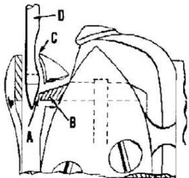
In the hook, at the right side of the needle hole in bobbin case holder (B, Fig. 15) is found a needle guarding surface (A, Fig. 15).
The purpose of this guarding surface is to prevent the hook point (C) from coming in contact with needle (D) at loop-taking time, should the needle be deflected toward the hook point. The needle guard will deflect the needle slightly when needle is at bottom of its vertical travel if the hook is properly timed. (At loop-taking time there should be little or no deflection of needle by the needle guard.)
text_image
A B C DFig. 15
For additional needle clearance, especially with use of larger needles, removal of some needle guarding surface may necessary.
Before metal removal from the guarding surface all related settings should be checked as follows:
- See that the needle bar is set to correct height.
- Check for proper hook timing.
- Rotate the handwheel in operating direction by hand. Check for excessive needle deflection beyond what is cited on preceding page as a desirable condition.
- If needle deflection is excessive, follow steps (A) and (B) below.
(A) Remove bobbin case holder from hook.
(B) Remove excess metal from the needle guarding surface. This may be done by using a diamond file No. TT60 or fine emery cloth (#320), with one end secured to the bench, and rubbing the guarding surface back and forth until sufficient metal is removed. When metal is being removed from needle guarding surface, the bobbin case holder should be reinserted frequently and tested until proper needle guarding is obtained.

text_image
B A CFig. 16

NEEDLE GUARD INSTRUCTIONS (CONT.)
CAUTION! Damage to the hook point may result if too much metal is removed from the needle guarding surface.
The bobbin case holder should be thoroughly cleaned before reassembly into the hook base.
When altering needle guarding surface, it is suggested that the hook NOT BE REMOVED or disturbed from its timed position.
The bobbin case holder only may be removed by removing gib screws and gib and pulling on bobbin case stem as the handwheel is rocked backward and forward slightly.

text_image
E A D C 1 F G J H 5 3/64 4 5/8Fig. 17
HOOK LUBRICATION
CAUTION! Do not run the machine without the bobbin case in the hook as hook damage may result.
With the bobbin case in hook, run machine for a full minute. Place a piece of white paper directly under the hook and continue running the machine. After about five seconds, remove the paper and a definite and distinct pattern of oil spots should be observed.
Should more or less oil be required, turn oil control adjusting shaft (H, Fig. 3), located on the front of the machine just blow the cloth plate surface, in direction of the change required. After a change in the hook oil flow, the machine should be run about one minute before checking for the desired oil flow.
PRESSER BARGUIDE
When locating presser bar guide (C, Fig. 17) presser foot must rest directly against throat plate. Proper setting of guide is 5 3/64 inches between underside of presser bar guide and the top of throat plate (Fig. 17). To obtain this setting, remove pressure from the presser spring (A) and loosen set screw (D). Tap on presser foot to insure it is down against throat plate. Set guide to the 5 3/64 inch dimension, center foot by turning it so needle enters the middle of its slot and retighten screw (D). Apply pressure to top (E) clockwise.
feed roller by turning regulator
Set needle thread pull-up bracket (F) so that underside of wire is 45/8 inches above throat plate (Fig. 17).
text_image
F E C B A DFig. 18
PRESER BAR CONNECTION
Presser bar convection (G, Fig. 17) should be set about 1/16 inch below prese bar guide (C). Accomplish this by loosening lick nut (A, Fig. 16), and relocating stop screw (B) on lifter lever bell crank (C), located at the back of machine, under bed plate. turning stop screw to right or left, properly sets presser car connection. Tighten lock nut (A) to lock stop screw.
TENSION ASSEMBLY ADJUSTMENT
Test check spring tension (A, Fig. 18). There should be enough tension to assure a good returning snap when the spring is depressed and released. Should it require adjusting, loosen set screw in head located under arm and to the right of tension assembly and remove tension assembly. Partially loosen tension post set screw (B) in tension post socket (C). Turn tension post (D) counterclockwise until check spring moves away from upper stop (E) and has no tension on it. Turn tension post (D) in a clockwise direction until spring again touches upper stop (E). Proceed further in same direction approximately 1/4 turn until desired tension is obtained. When correctly set, tension post set screw (B) should be drawn up snugly, yet not forcefully. Further adjustment of check spring tension can be made by inserting a screwdriver into slotted end of tension post (D) and turning in required direction.
text_image
3" 8 1" to 1" 16 A B CFig. 19
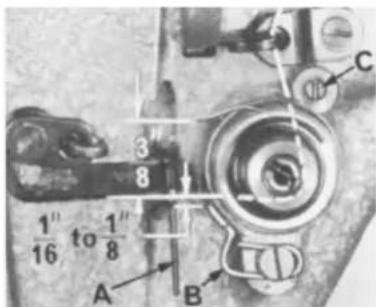
Replace tension assembly with check spring about 3/8 inch above thread take-up bracket (A, Fig. 19). Replace tension post assembly while presser foot is resting on throat plate.
TENSION RELEASE
Tension release should be set so as not release when sewing over seams or when presser foot is raised. Adjustment of tension release cam (H, Fig. 17) and in and out position of tension assembly are required for proper operation.
The in and out position of the tension assembly is correct when the tension discs are in line with the check spring eyelet (B, Fig. 19). Set the stop screw (C, Fig. 19) so that when the flange of the tension assembly rests against it, this position is maintained. Tighten the tension assembly set screw.
text_image
A B C HIVI 01230Fig. 20
The tension release cam (H, Fig. 17) should now be positioned by loosening set screw (J) and then rising or lowering cam (H) to suit the sewing conditions. The average release point is between 1/4 and 5/16 inch of presser foot lift above the throat plate. Tighten tension release cam set screw securely.
THREAD CONTROL
Check the adjustment of tension assembly (A, Fig. 20) and check spring tension. There should be enough tension to insure a good returning snap when spring (B, Fig. 20) is depressed and released. The check spring tension is adjusted from about 1 to 1 1/4 ounces when measured with a postal scale, No. 21227DN, (C, Fig. 20). This is measured when the check is 1/32 to 1/16 inch from the stop. The tension post set screw should be drawn up snugly but not forcefully tightened (B, Fig. 18). The tension release pin should move freely in the tension post (D, Fig. 18). The check spring eyelet (B, Fig. 19), located just below the tension discs, should be set for correct height as follows:

text_image
AFig. 21
With a thread running from the tension post to the thread take-up bracket (A, Fig. 19) in a straight line, the check spring eyelet should be set 1/16 to 1/8 inch below the thread line (Fig. 19). Be sure the eyelet is set close to the tension discs so that the check spring will pass freely over it without obstruction. After making this setting, proceed to thread machine as per threading diagram (Fig. 3).

THREAD CONTROL(CONT.)
Sew slowly on a piece of material and observe the action of the check spring. The thread from the check spring to the take-up bracket should be taut when the take-up is at the bottom if its stroke. Slight changes in needle thread tension may necessary at this point, but a reasonable tension should be used to maintain a uniform and consistent stitch. The machines are sewn off with 4 to 8 ounces maximum needle thread tension on T120 or similar thread, using a postal scale (A, Fig. 21). Depress check spring when checking tension. The check spring will feel heavy to you, but this is a required setting for Class 63900, and as a result, the tension on the discs can be reduced.
BOTTOM COVER
Before removing bottom cover, place machine on bench so that the plug screw is accessible from underneath. Remove this plug screw and catch reservoir oil in some convenient container. Tip machine back, loosen and remove the two cover screws. Cover should be tapped free with a wooden block or mallet. Do not pry the cover loose with any sharp instrument as the gasket may become damaged.
CAUTION! When the bottom cover is removed, care should be taken not to mar or scratch the gasket seat area of the machine bottom.
Before replacing cover, the machine gasket seat should be wiped clean and free of all lint and dirt. The cover gasket should also be inspected for damage and cleaned of dirt. Two additional gaskets are used to seal the bolts and must be cleaned before assembly. Carefully set the cover in place and tighten the two bolts securely.
To replace a damaged cover gasket, proceed as follows:
-
Clean cover gasket recess of any foreign matter.
-
The gasket in cross section is triangular in shape with a groove in the top or widest part. With the cover resting as it does in the machine, oil distributing plate to your right, begin inserting in the middle of the back recess. The grooved wide edge of the gasket should be up and the ling sloped edge inward. Continue pressing the gasket into the cover recess until gasket is in place.
The bolt sealing gaskets may have a tendency to fall out when the cover is being installed and may be temporarily cemented in place by applying grease to their recesses. Torque to 72 inch lbs.
HOOK SHAFT
text_image
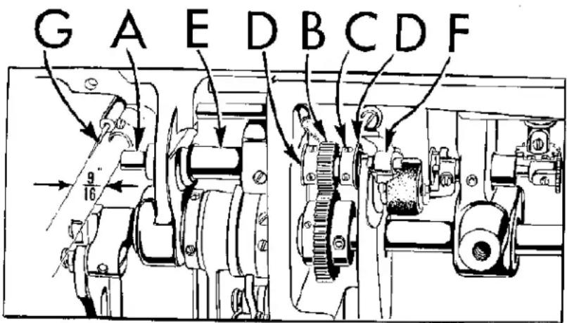
G A E D B C D F 9" 16Fig. 22
The hook shaft (A, Fig. 22) is held in position by the pinion (B) and collar (C) thrusting against hard steel washers (D) between the long left hand bushing (E) and the short right hand bushing (F).
Should hook shaft setting be disturbed, the left and right position can be determined by measuring from the hook end of the hook shaft to the point of a new needle (G) and reading 9/16 inch on a scale.
HOOK SHAFT (CONT.)
To reposition the hook shaft, loosen the set screws of the pinion and collar and establish the 9/16 inch dimension. Move the pinion and thrust washer against the left bushing, and after making certain one of the set screws in on the shaft FLAT, tighten both screws securely. Liberally coat the collar and its washer with oil and press the collar away from the pinion so as to remove all end play and tighten both set screws securely.
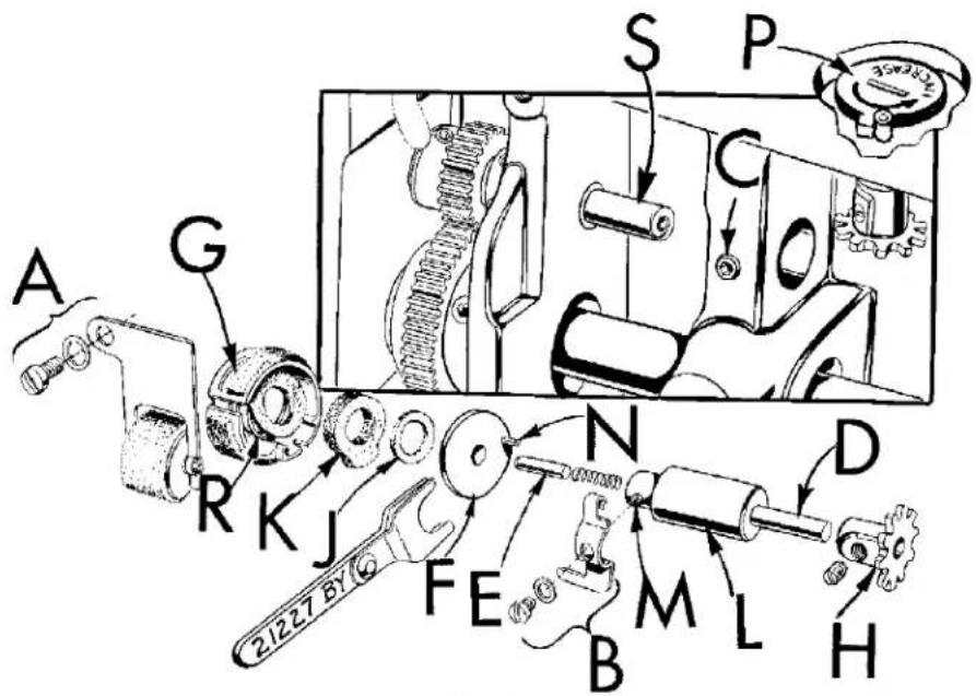
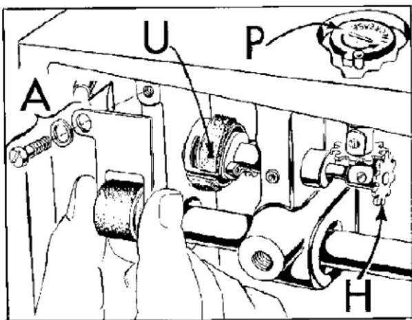
Hook oiling is accomplished by a high speed rotary pump on the end of the hook shaft. The quantity of oil supplied to the hook is regulated by the longer or shorter path the oil is required to travel through the metering felt of metering cup (G, Fig. 23). (Increase or decrease of oil supply is controlled by a dial (P, Fig. 23) with an arrow marked "INCREASE", found below the cloth plate.) The hook oil feed roller (A, Fig. 23) which rests against the metering cup felt serves not only to feed oil to the unit from the oil reservoir, but filters the oil as well.

text_image
A G R K J 21227 BY FE N B M L D H C P SFig. 23
REMOVAL OF OILING DEVICE
The following steps are necessary to remove hook oiling device:
- Remove hook oil feed roller (A, Fig. 23).
- Remove hook oil control finger (B).
- Apply finger pressure to hook oil control shaft (D) to prevent loss pump disc pivot pin (E); using Allen wrench, loosen set screw (C). Move assembly slowly to right, being careful not to drop pivot pin located on the end of the hook oil control shaft. When pivot pin is clear of pump disc (F), disc is free to fall.
- Remove metering cup (G) along with oil supply felt (K) and air seal felt (J).
- Remove cop (H) from hook oil control shaft.
REASSEMBLY OF OILING DEVICE
Before reassembly, the end of the hook shaft, its spiral groove and the pump disc should be thoroughly cleaned. Remove any end play found in the hook shaft and determine that the 35/64 inch dimension has been maintained (Fig. 22).
The following steps are necessary to reassemble the hook oiling device:
-
Remove and separate the air seal felt (J, fig. 23) from oil supply felt (K).
-
Make sure small end of air seal spring (R) is located on boss of metering cup behind felt attached to cup. Position the metering cup (G) and air seal spring on the hook shaft (S) with open end toward handwheel end of the machine (Fig. 23).
NOTE: The hook shaft should pass through hole of felt attached to metering cup.
-
Position oil supply felt (K, Fig. 23) on the hook shaft, making certain the felt's projection extends into dovetail of metering cup.
-
Position air seal felt (J) on hook shaft.
text_image
A G R K J 21227 BY FE N B M L H D C S PFig. 23
-
Insert pump disc (F) into assembly tool No. 21227BY, with the stop pin on the spring side of tool, 180° from handle. Insert disc approximately half way into the spring and center in tool (Fig. 25).
-
Insert hook oil control shaft (D, fig. 23) and its bushing (L) part way into its boss which is located directly behind the hook shaft, being careful NOT TO DROP the pump disc pivot pin (E).
REASSEMBLY OF OILING DEVICE (CONT.)
-
A clearance cut on the edge of the metering cup, located between the dovetail and the long horizontal slot, has been provided for the pump disc tool and should be facing you (Fig. 25).
-
With the fork of the tool in line with the metering cup clearance cut and centered about the hook shaft end, press felts to the left with tool until the pump disc is in contact with end of the hook shaft.
-
Press hook oil control shaft bushing (L) to the left until control shaft (D) is approximately 1/16 inch away from pump disc (F). Make sure the control shaft pivot pin (E) seats in the depression at the center of the pump disc. Tighten set screw (C, Fig. 25) and withdraw assembly tool. Be sure sir seal felt (J) has seated against the pump disc.
-
Turn the hook oil control shaft (D, Fig. 26) until screw hole (M) is accessible. Manually rotate pump disc (F) so its stop pin (N) is 90° above screw hole.
-
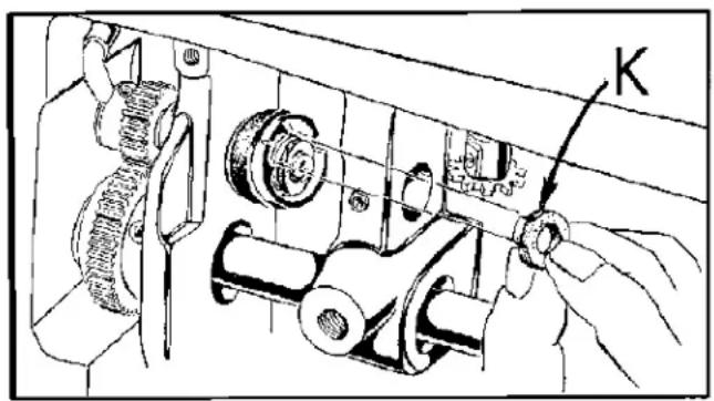
Rotate metering cup so the short slot (T) is 180^ from stop pin (N). Now, install hook oil control finger (B) by first hanging the hooked portion of finger over the stop pin and lowering to insert the projection at bottom left into the short slot of the metering cup. Tighten the finger in place by means of screw and washer, making sure the hook oil control finger does not bind or distort metering cup.
-
Assemble the hook oil feed roller (A, Fig. 27), and rotate the metering cup so that the roller contacts the metering cup felt at point (U, Fig. 27). Turn the oil control adjusting shaft (P, Fig. 27) in the increase direction until projection stops against the stop in (this is maximum oil supply) and install the cog (H, Fig. 27) on the hook oil control shaft. After meshing the teeth, tighten set screw securely.
-
Check for proper contact of the hook oil feed roller and the metering cup by turning the oil control adjusting shaft through its complete travel and observe the feed roller turning as the metering cup turns. With the oil control adjusting shaft set at maximum, the feed roller point of contact with the metering cup felt should be at the mid-point of the slot that permits the metering cup felt to enter the metering cup.
text_image
Technical diagram of a mechanical assembly with labeled component 'K' and directional arrow indicating motion or assembly.Fig. 24
natural_image
Technical line drawing of a mechanical assembly with gears and levers (no text or symbols)Fig. 25
NOTE: The feed roller should be in contact with the metering cup felt through its complete travel.
UPPER MAIN SHAFT
In a high speed machine, the alignment of the take-up mechanism is extremely important and is controlled by the left and right position of the upper main shaft. Should the main shaft position be altered, it is imperative that the take-up alignment be checked before operating.
UPPER MAIN SHAFT (CONT.)
TO CHECK FOR ALIGNMENT
- Remove the presser bar spring, washer and regulator screw.

text_image
F N D T M BFig. 26
-
Rotate the handwheel so that the needle bar is at the bottom of its stroke. Loosen hexagonal head screw on back of the presser bar roller bracket, and set screw on left side or roller bracket. Then loosen screw on presser bar guide and remove presser bar, presser bar spring washer and presser bar guide.
-
Remove the upper left plastic plug on the back of the machine and loosen screw in plug hole. Remove take-up lever pin. With light inward finger pressure, move the take-up lever to the take-up lever boss. There should be a small amount of interference between the lever and the boss. With light outward finger pressure, move the lever across the boss face. There should be clearance between the boss face and lever. These two tests, in effect, are checking the lateral play of the take-up and provide for operation of the take-up in the center of the lateral play. Now, line up the take-up lever hole in the lever boss.
Insert the oil wick about 1/2 inch in the bore of the take-up lever. With the oil groove up, insert the take-up lever pin in the lever, making sure the wick is in the groove and press the pin into its hole in the arm. There should be no end play in the take-up lever after the set screw is securely tightened. Replace the plastic plug.
text_image
U P A HFig. 27
Replace presser bar guide and presser bar spring washer into position. Place presser bar into presser bar roller bracket with flat on bar to the rear and tighten hex head screw and set screw securely.
Line up needle hole in the presser foot with the needle and tighten presser bar guide screw.
Assemble presser spring, presser spring washer and presser spring regulator screw.
Refer to paragraph on "Presser Bar Guide" for proper setting of the guide.
Should the alignment test show the main shaft is out of position, the upper sprocket and handwheel should be loosened and the shaft moved left or right as the conditions indicate. Retighten sprocket and handwheel so that there is no end play in the upper main shaft and
repeat the alignment check.
HANDWHEEL
The handwheel is constructed so as to minimize noise and is therefore isolated from the pulley by shock mounts. If for any reason the handwheel is disassembled, the following steps should be used for reassembly.
HANDWHEEL (CONT.)
- Using the upper main shaft as a mandrel, assemble the pulley thrust face down so that at least 1 1/2 inches of the shaft protrudes above it. Tighten the two set screws.
- Place the rubber isolator ring on the pulley face and align holes.
- Carefully slide handwheel down the shaft to contact the isolator and align the three holes.
- Three plastic "O" rings are now inserted into their respective holes in the handwheel.
- The outer isolator rings and cap are assembled.
- Insert the three screws that are run through the complete assembly and tighten lightly.
- Loosen the two pulley screws and slowly revolve the whole assembly several times for good alignment. Now, gradually tighten the three screws, moving from one to the other until all are snug.
- The assembly should run true as it revolves freely on the shaft. If any sidewise run-out is noted, it can be corrected by slight changes of screw pressure in the three isolator screws.
CAUTION! When replacing the handwheel assembly on the main shaft, care must be taken not to damage the oil seal located near the end of the shaft. The surface of the ring should be lightly oiled and the handwheel worked over the seal gently.
ATTACHMENTS
Style 63900AM, AML is equipped with a retractable hemmer (A, Fig. 28) which produces 3/8 to 1/2 inch width of hem. To adjust to desired width loosen two screws (B & C) and slide hemmer scroll (D) to the right or left.
To change the sewing margin loosen screws (E & F) and slide the hemmer (A) to the right or left to obtain desired margin.
Style 63900AT is equipped with an adjustable edge guide for producing margins from 1/2 to 2 1/2 inches wide. For margins wider than 1 5/16 inches the base of the edge guide must be reversed.
To change margin relocate edge guide in holes provided until desired margin is obtained.
Style 63900AAE, AW is equipped with a cloth plate extension to provide a platform for guiding trousers. It is easily attached to the machine by three No. 22517B screws.

text_image
D A E FFig. 28
NEEDLE HOLE INSERT (SEE PAGE 44)
The throat plate has a replaceable needle hole insert. To remove this insert, drive it out from the underside of the throat plate.

text_image
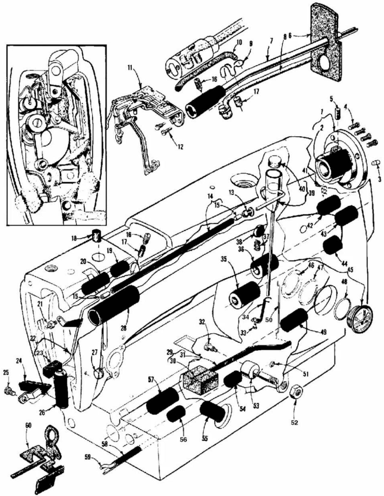
Technical diagram of a mechanical device with numbered components and exploded view, likely for assembly or maintenance purposes.MAINFRAME, BUSHING, OIL GAUGE HEAD OIL SIPHON AND MISCELLANEOUS OILING PARTS
| Ref. | Amt. | ||
| No. | Part No. | Description | Req. |
| 1. | 61490B | Main Shaft Bushing Housing, including bushing | 1 |
| 2. | 61490C | Bushing | 1 |
| 3. | 63949R | Plug, for bed | 1 |
| 4. | 22569B | Screw | 4 |
| 5. | 666-200 | Oil Felt | 1 |
| 6. | 666-254 | Felt Baffle | 1 |
| 7. | 63993D | Head Oil Supply Line | 1 |
| 8. | 666-225 | Felt | 1 |
| 9. | 63984C | Spring Clip | 1 |
| 10. | 666-223 | Roll Felt | 1 |
| 11. | 63993C | Head Oiler Assembly | 1 |
| 12. | 22784K | Screw | 2 |
| 13. | 61494N | Retaining Grommet | 1 |
| 14. | 63494M | Oil Siphon Connecting Tube | 1 |
| 15. | 56393AA | Oil Tube | 2 |
| 16. | 22815 | Plug Screw | 1 |
| 17. | 666-224 | Roll Felt | 1 |
| 18. | 666-228 | Oil Felt | 1 |
| 19. | 61985H | Needle Bar Frame Rocker Shaft Bushing, right | 1 |
| 20. | 61985G | Needle Bar Frame Rocker Shaft Bushing, left | 1 |
| 21. | 61494L | Stud | 1 |
| 22. | 63994 | Oil Siphon Head Tube | 1 |
| 23. | 666-214 | Oil Felt | 1 |
| 24. | 63953A | Oil Shield | 1 |
| 25. | 22564 | Screw | 1 |
| 26. | 63957A | Presser Bar Bushing, lower | 1 |
| 27. | 51-159BLK | Plug | 1 |
| 28. | 61490D | Upper Main Shaft Bushing, left | 1 |
| 29. | 63494C | Oil Gauge Float Assembly | 1 |
| 30. | 61494D | Oil Gauge Float | 1 |
| 31. | 61494E | Oil Gauge Float Lever | 1 |
- thru 60. see following page.
text_image
Technical diagram of a mechanical device with numbered components and exploded view, likely for assembly or maintenance purposes.MAINFRAME, BUSHING, OIL GAUGE HEAD OIL SIPHON AND MISCELLANEOUS OILING PARTS (CONT.)
| Ref. | Amt. | ||
| No. | Part No. | Description | Req. |
-
thru 31. see preceding page.
-
22890C Screw 1
- 22564 Screw 1
- 63993H Oil Siphon Primer Position Bracket 1
- 63962D Lower Reduction Gear Shaft Bushing, left 1
- 63962G Upper Reduction Gear Shaft Bushing, left 1
- 666-238 Bed Oil Drain Hole Felt 1
- 61293N Bed Plug 1
- 63494D Oil Siphon Priming Cup 1
- 666-237 Cup Felt 1
- 666-221 Oil Wick, for bushing housing 1
- 63962E Middle Reduction Gear Stud Bushing 1
- 63962F Upper Reduction Gear Shaft Bushing, right 1
- 63962C Lower Reduction Gear Shaft Bushing, right 1
- 63494K Oil Gauge Assembly 1
- 63494F Nut 1
- 63494G Spring Washer 1
- 660-455 "O" Ring 1
- 61432B Hook Drive Shaft Bushing, right 1
- 61494H Oil Gauge Connecting Link 1
- 660-221 "O" Ring 1
- 11635B Nut 1
- 61494T Float Lever Pivot Stud 1
- 61496P Hook Oil Control Shaft Bushing 1
- 61496S Hook Oiling Control Adjusting Bushing 1
- 61441A Hook Shaft Bushing, right 1
- 63432C Hook Drive Shaft Bushing, left 1
- 63993B Hook Shaft Bushing Oil Tube 1
- 666-239 Oil Wick 1
- 666-234 Head Oil Attraction Felt 1
- 63490B Gasket (not shown) 1
text_image
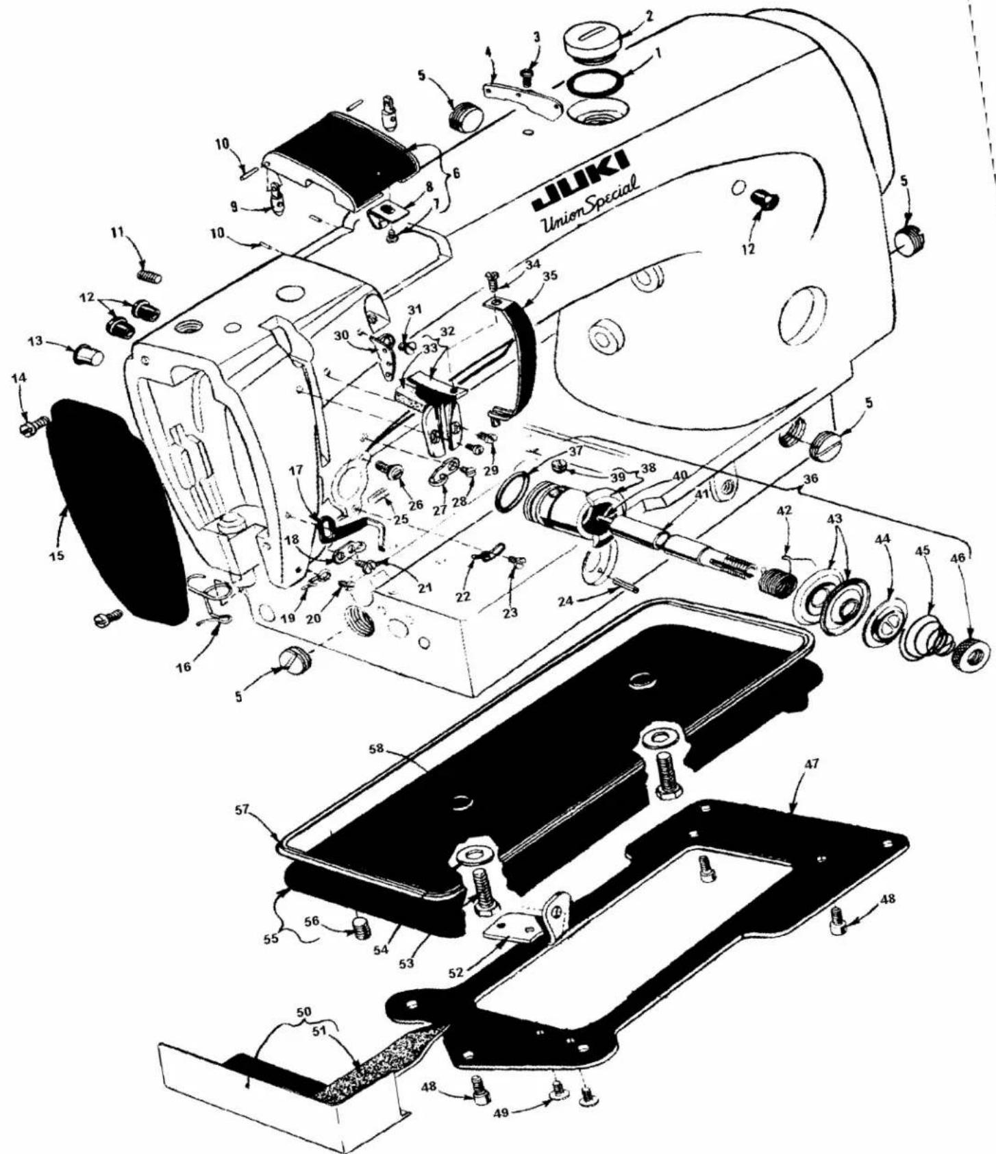
JUKI UnionSpecialMAIN FRAME MISCELLANEOUS COVERS AND NEEDLE TENSION PARTS
| Ref. | Amt. | ||
| No. | Part No. | Description | Req. |
- 63494A Gasket 1
- 22733D Plug Screw, for oil filler hole 1
- 22570A Screw 1
- 61470D Frame Thread Eyelet 1
- 22539P Plug Screw 4
- 63982A Top Cover 1
- 22513D Screw 1
- 63982F Spring Clip 1
- 61982C Top Cover Hinge 2
- 61982D Top Cover Hinge Pin 4
- 22894E Screw 1
- 63994C Plug, plastic, overall length 7/16 inch (11.1mm) 6
- 660-409 Tension Release Bushing Plug 1
- 22516 Screw 2
- 63982 Head Cover 1
- 63970B Needle Bar Bushing Thread Guide 1
- 63970A Thread Pull-up Bracket 1
- 63470A Upper Needle Thread Eyelet 1
- 63470 Lower Needle Thread Eyelet 1
- 90 Screw 1
- 22766 Screw 1
- 63492 Tension Post Eyelet 1
- HS24C Screw 1
- 660-219A Roll Pin 1
- 22597E Set Screw, for tension assembly 1
- 22863B Stop Screw, for tension assembly 1
- 61470C Thread Guide 1
-
22766 Screw 1
-
thru 58. see following page.

text_image
JUKI UnionSpecialMAIN FRAME MISCELLANEOUS COVERS AND NEEDLE TENSION PARTS (CONT.)
| Ref. | Amt. | ||
| No. | Part No. | Description | Req. |
- thru 28. see preceding page.
| 29. | 22562 | Screw | 2 |
| 30. | 61471A | Frame Thread Eyelet | 1 |
| 31. | 22805 | Screw | 1 |
| 32. | 63971A | Take-up Lever Shield | 1 |
| 33. | 666-222 | Felt Pad | 1 |
| 34. | 22564 | Screw | 1 |
| 35. | 63451 | Take-up Shield | 1 |
| 36. | 29475AR | Thread Tension Assembly | 1 |
| 37. | 660-269A | Quad Ring | 1 |
| 38. | 61492E | Tension Post Socket | 1 |
| 39. | 22560G | Set Screw | 1 |
| 40. | 61492G | Tension Release Pin | 1 |
| 41. | 61492F | Tension Post | 1 |
| 42. | 63453 | Take-up Spring | 1 |
| 43. | 109 | Tension Disc | 2 |
| 44. | 61492H | Tension Release Washer | 1 |
| 45. | 61392F14 | Tension Spring | 1 |
| 46. | 61292C | Tension Nut | 1 |
| 47. | 21680AX | Base Plate | 1 |
| 48. | 22652D8 | Screw, for base plate | 3 |
| 49. | 22517B | Screw | 2 |
| 50. | 63996 | Hook Oil Return Channel | 1 |
| 51. | 666-240 | Hook Oil Return Channel Felt | 1 |
| 52. | 21662AE | Shaft Bracket, rear | 1 |
| 53. | 22644K48 | Screw | 2 |
| 54. | 652-16 | Washer | 2 |
| 55. | 63982C | Oil Reservoir Bottom Cover | 1 |
| 56. | 22571F | Plug Screw | 1 |
| 57. | 61482J | Gasket | 1 |
| 58. | 660-204 | "O" Ring | 2 |

text_image
Align flats on right end with centerline of hole for take-up lever crank pin 1A 2 3 4 5 6 7 8 9 10 11 12 13 14 15 16 17 18 19 20 21 22 23 24 25 26 27 28 29 30 31 32 33 34 35 36 37 38 39 40 41 42 43 44 45 46 47 48 49 50 51 52 53 54 55| Ref. No. | Part No. | Description | Amt. Req. |
| 1. | 63917C | Needle Bar, marked "EN" | 1 |
| 2. | 63443 | Hook Shaft Driving Gear | 1 |
| 3. | 22894C | Set Screw | 2 |
| 4. | 63940 | Hook Driving Shaft | 1 |
| 5. | 63993G | Oil Return Pump | 1 |
| 6. | 61360G | Shaft Collar | 1 |
| 7. | 22884 | Screw | 2 |
| 8. | 61460A | Hook Driving Shaft Sprocket | 1 |
| 9. | 22653D6 | Screw | 2 |
| 10. | 61460B | Feed Driving Belt | 1 |
| 11. | 660-269 | Quad Ring | 1 |
| 12. | 63921 | Handwheel Assembly | 1 |
| 13. | 61421G | Hub Washer | 1 |
| 14. | 22574C | Screw | 3 |
| 15. | 63921BA | Handwheel | 1 |
| 16. | 22894V | Set Screw | 2 |
| 17. | 652B20 | Lock Washer | 1 |
| 18. | 61468B | Lifter Lever Extension Stud and "S" Hook | 1 |
| 19. | 421H | Lifter Lever Chain | 1 |
| 20. | 22890A | Screw, left thread | 1 |
| 21. | 63466 | Lifter Lever | 1 |
| 22. | 61467 | Lifter Lever Link | 1 |
| 23. | 22758B | Screw | 1 |
| 24. | 15872F | Lifter Lever Spring | 1 |
| 25. | 22817A | Screw | 1 |
| 26. | 660-283A | Spring Grip Fastener | 1 |
| 27. | 61468D | Chain Hook | 1 |
| 28. | 63479E | Main Shaft Reduction Drive Gear | 1 |
| 29. | 22651CD-3 | Set Screw | 2 |
| 30. | 61460 | Main Shaft Driving Sprocket | 1 |
| 31. | 22884 | Set Screw | 2 |
| 32. | 9937 | Nut | 1 |
| 33. | 22874F | Screw | 1 |
| 34. | 63422 | Main Shaft | 1 |
| 35. | 63491D | Counterweight | 1 |
| 36. | 22839 | Screw | 2 |
| 37. | 22894W | Spot Screw | 1 |
| 38. | 22894V | Set Screw | 2 |
| 39. | 29486AB | Take-Up Lever and Needle Bar Link Assembly | 1 |
| 40. | 61451 | Take-Up Lever | 1 |
| 41. | 61451G | Take-Up Lever Eyelet | 1 |
| 42. | 61451D-625 | Needle Bearing, .625 inch diameter | 38 |
| 61541D-626 | Needle Bearing, .626 inch diameter | 38 | |
| 61541D-627 | Needle Bearing, .627 inch diameter | 38 | |
| 43. | 61455 | Needle Bar Link | 1 |
| 44. | 22757D | Screw | 1 |
| 45. | 63455 | Thrust Washer | 1 |
| 46. | 63952C | Take-Up Lever Crank Pin, marked "L" | 1 |
| 47. | 61451A | Take-Up Lever Link | 1 |
| 48. | 61351C | Thrust Washer | 1 |
| 49. | 22784E | Screw | 1 |
| 50. | 61255 | Needle Bar Connection | 1 |
| 51. | 22562B | Screw | 1 |
| 52. | 61451B | Take-Up Lever Pin | 1 |
| 53. | 61468F | Lifter Lever Bell Crank | 1 |
| 54. | 61468E | Bell Crank Roller | 1 |
| 55. | 22712G | Screw | 1 |
text_image
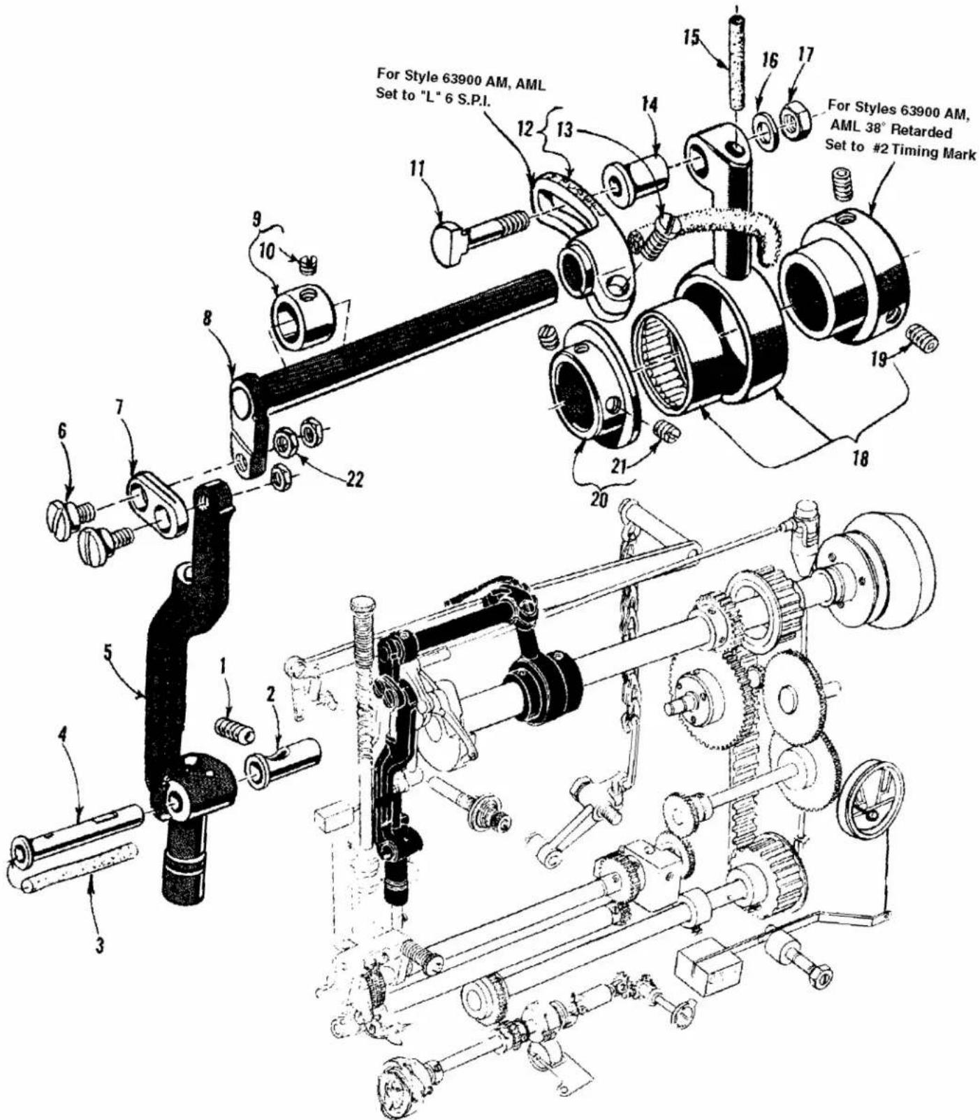
For Style 63900 AM, AML Set to "L" 6 S.P.I. For Styles 63900 AM, AML 38° Retarded Set to #2 Timing Mark For Styles 63900 AM, AML 38° Retarded Set to #2 Timing Mark
NEEDLE FEED DRIVING PARTS
| Ref. | Amt. | ||
| No. | Part No. | Description | Req. |
- 22894E Screw, for needle bar frame pivot stud .... 1
- 61985J Needle Bar Frame Pivot Adjustable Bushing 1
- 666-139 Oil Wick 1
- 61985A Needle Bar Frame Pivot Stud 1
- 63985B Needle Bar Frame 1
- 22504H Screw 2
- 61985D Needle Bar Frame Rock Shaft Connecting Link 1
- 61985A Needle Bar Frame Rock Shaft 1
- 51773 Collar.... 1
- 88B Screw.... 1
- 61984C Needle Bar Drive Eccentric Connecting Stud 1
- 61985F Needle Bar Frame Rock Shaft Driving Lever 1
- 22839 Clamp Screw 1
- 60038G Bearing 1
- 666-173 Oil Wick 1
- 20 Washer 1
- 18 Nut.... 1
- 29126EL Needle Feed Drive Eccentric and Connecting Rod Assembly 1
- 22894J Set Screw 2
- 63984A Needle Bearing Retaining Collar 1
- 95 Screw 2
- 14077 Nut 3
text_image
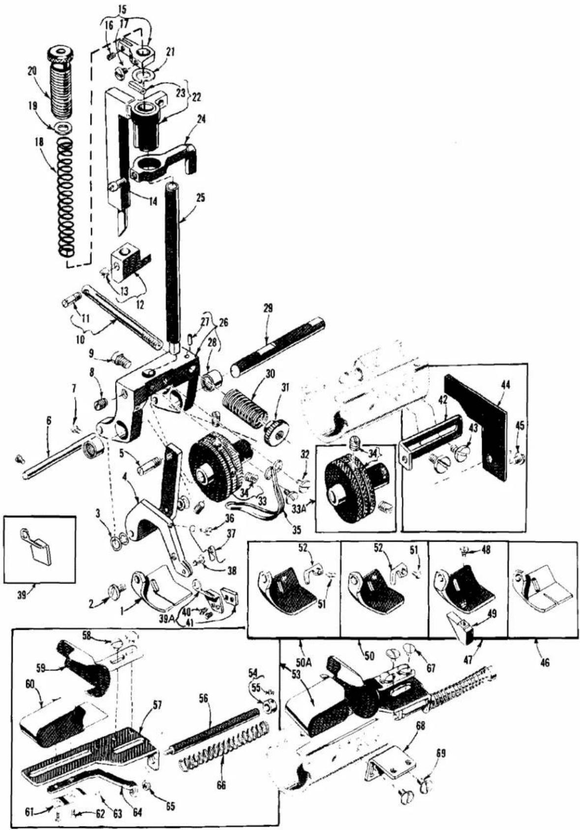
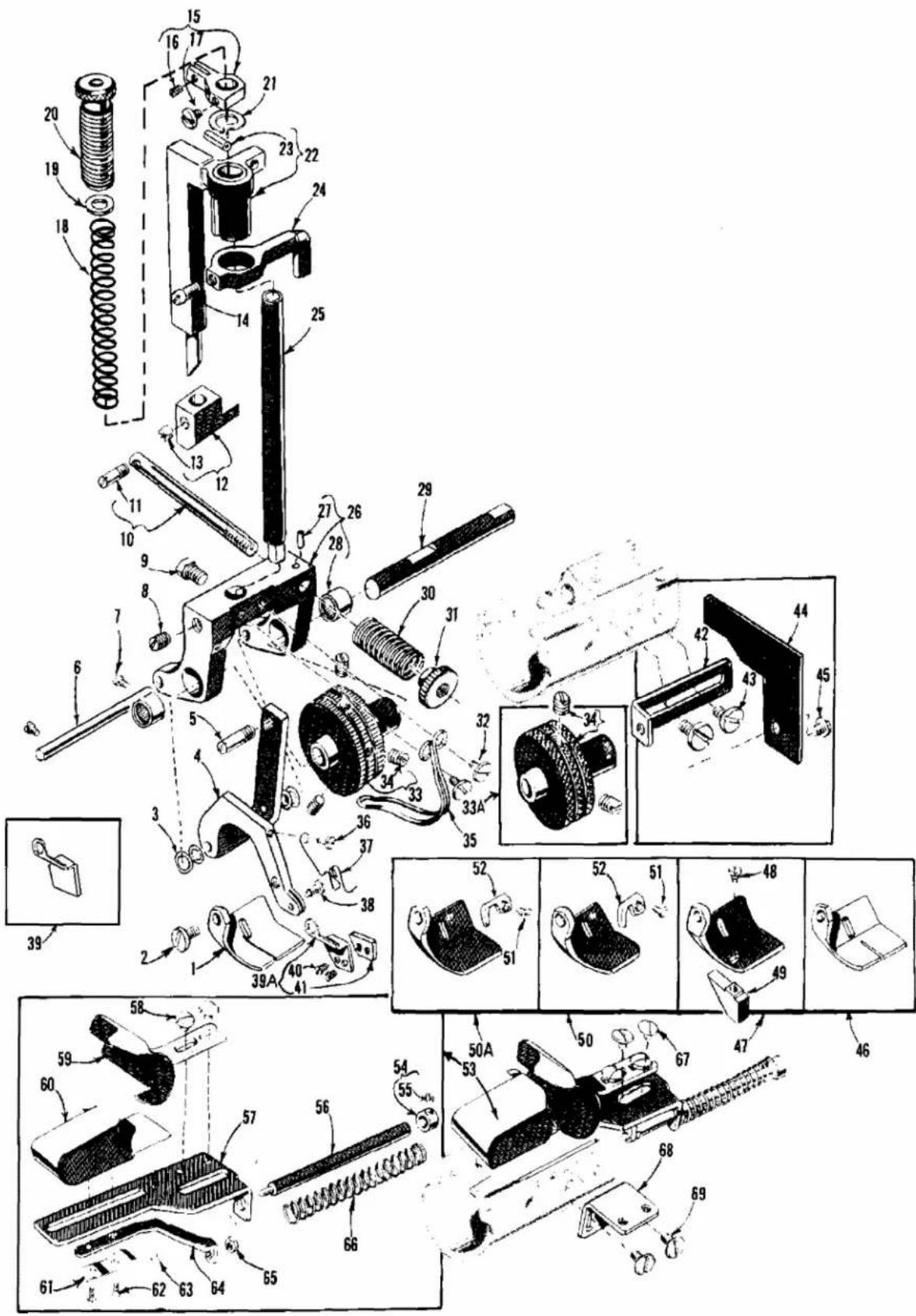
Exploded view diagram of a mechanical assembly with numbered parts and exploded viewsPRESSER FEET, PRESSER BAR, TOP FEED ROLLER MECHANISM AND ATTACHMENTS
| Ref. | Amt. | ||
| No. | Part No. | Description | Req. |
- 63920 Presser Foot, marked "AF", for Style 63900AW 1
- 22585A Screw 1
- 27-435BLK Washer 4
- 61458H Presser Foot Shank 1
- 21756G Screw Pin 1
- 61439AN Presser Foot Shank Hinge Pin 1
- 22738B Screw 2
- 95 Set Screw, for presser bar 1
- 22882 Screw, for presser bar 1
- 61458D Presser Foot Tension Bar 1
- 22845 Screw Pin 1
- 61458C Presser Foot Lifter Block 1
- 88B Screw 1
- 230 Screw 1
- 63959B Presser Bar Guide 1
- 73C Screw 1
- 22570 Screw 1
- 61356 Roller Presser Spring 1
- 61256G Presser Spring Washer 1
- 61257G Presser Spring Regulator and Bushing 1
- 63457R Presser Bar Spring Washer 1
- 63958 Presser Bar Connection 1
- 660-219B Roll Pin 1
- 61458G Tension Release Cam 1
- 63957 Presser Bar 1
- 61439AM Top Roller Bracket 1
- 54430E Pin 1
- 660-249 Needle Bearing 2
- 63939K Top Feed Roller Shaft 1
- 110-4 Presser Foot Tension Regulating Spring 1
- 51292C Presser Foot Tension Regulating Nut 1
- 138 Screw 2
- 63939R Top Feed Roller, 48 teeth, 1 1/4 inch diameter 1
*33A. 61439AG Top Feed Roller, coarse knurl, 1 1/4 inch diameter 1 - 95 Set Screw 2
-
61439AP Upper Roller Stripper 1
-
thru 69. see following page.
* Available if specified on order or as an extra send and charge item.
text_image
Technical diagram of a mechanical assembly with numbered components and exploded viewsPRESSER FEET, PRESSER BAR, TOP FEED ROLLER MECHANISM AND ATTACHMENTS
| Ref. | Amt. | ||
| No. | Part No. | Description | Req. |
- thru 35. see preceding page.
| 36. | 22798A | Screw, for Styles 63900AW, AEE | 1 |
| 37. | 61430V | Spring, for edge guide, for Styles 63900AW, AEE | 1 |
| 38. | 21629 | Screw, for compensating edge guide, | 1 |
| 39. | 61430CL | Edge Guide, for Style 63900AEE | 1 |
| 39A. | 61430BW | Compensating Edge Guide, for Style 63900AW | 1 |
| 40. | 22738F | Screw | 2 |
| 41. | 61430BX | Compensating Edge Guide | 1 |
| 42. | 63903 | Edge Guide Mounting Bracket, for Style 63900AT | 1 |
| 43. | 22875 | Screw, for edge guide mounting bracket | 2 |
| 44. | 61403 | Edge Guide, for Style 63900AT | 1 |
| 45. | 22704 | Screw | 1 |
| 46. | 63930A | Presser Foot Bottom, for Style 63900AAE | 1 |
| 47. | 63920A | Presser Foot, for Style 63900AT | 1 |
| 48. | 73A | Screw | 1 |
| 49. | 61430R | Presser Foot Edge Guide | 1 |
| 50. | 63920B3/8 | Presser Foot, for 3/8 inch hem, on Style 63900AM | 1 |
| 50A. | 63920B1/2 | Presser Foot, for 1/2 inch hem, on Style 63900AM | 1 |
| 51. | 22738B | Screw | 1 |
| 52. | 61430X | Presser Foot Needle Guard, marked "A" | 1 |
| 53. | 23564 | Hemmer, complete, for making 3/8 to 1/2 inch turned don hem, on Style 63900AM | 1 |
| 54. | 6958 | Collar | 1 |
| 55. | 88 | Set Screw | 1 |
| 56. | 23564E | Hemmer Operating Rod | 1 |
| 57. | 23564D | Hemmer Base | 1 |
| 58. | 22711 | Screw | 2 |
| 59. | 23564A | Hemmer Scroll, right | 1 |
| 60. | 23364AD | Hemmer Scroll, left | 1 |
| 61. | 23364AG | Hemmer Scroll Slide Spring | 1 |
| 62. | 22593 | Screw | 2 |
| 63. | 91A | Stop Screw | 1 |
| 64. | 23564C | Hemmer Scroll Slide | 1 |
| 65. | 907 | Nut | 1 |
| 66. | 20110 | Hemmer Operating Rod Spring | 1 |
| 67. | 22711 | Screw, for hemmer, on Style 63900AM | 2 |
| 68. | 23564G | Hemmer Mounting Bracket | 1 |
| 69. | 22517B | Screw | 2 |

text_image
Exploded view diagram of a mechanical assembly with numbered parts for identificationROTATING HOOK ASSEMBLY AND HOOK OILING PARTS
| Ref. | Amt. | ||
| No. | Part No. | Description | Req. |
- 29474SA Rotating Hook Assembly for 63900AAE, AT, AW 1
- 29474AH Rotating Hook, for Style 63900AML, 1/2, 3/8, AMLZ 1
- 29474VA Rotating Hook, for Style 63900AM, 1/2, 3/8 1
-
63913A Bobbin Case Assembly 1
-
61415A Bobbin Case Latch Lever 1
-
61216 Bobbin Case Latch Hinge Pin 1
-
61216N Bobbin Case Latch Spring 1
-
22564M Screw 2
-
22716K Tension Regulating Screw 1
-
61414F Bobbin Case Tension Spring 1
-
63918A Bobbin Case 1
-
61415 Bobbin Case Latch 1
-
61212B Bobbin 1
-
63914D Bobbin Case Holder 1
-
63907A Hook, Thread Retainer and Thread Deflector Assembly 1
-
61411B Hook Thread Retainer 1
-
22716M Screw 3
-
22569H Set Screw 2
-
63908 Hook 1
- 63408 Hook, for Styles 63900AML1/2, 3/8 1
-
61210C Hook Thread Deflector 1
-
22716L Screw 4
-
61351C Thrust Washer 2
-
12865 Thrust Collar 1
-
88 Screw 2
-
61444 Hook Shaft Pinion 1
-
89 Screw 2
-
61440 Hook Shaft 1
-
63432 Hook Shaft Collar, left 1
-
HA73B Screw 2
-
61496V Hook Shaft Wick Insert Assembly 1
-
22868D Screw 1
-
51225W Washer 1
-
61496F Retaining Spring 1
-
61496G Pivot Pin 1
-
61496E Hook Oil Feed Roller 1
-
63496B Metering Cup 1
-
61496J Air Seal Spring 1
-
666-181 Oil Supply Felt 1
-
666-182 Air Seal Felt 1
-
61496C Pump Disc 1
-
660-219D Roll Pin 1
-
61496D Pump Disc Pivot Pin 1
-
35857R Spring.... 1
-
61496L Hook Oil Control Shaft 1
-
61496K Hook Oil Control Finger 1
-
27-527BLK Washer 1
-
22819 Screw 1
-
61496P Hook Oil Control Shaft Bushing 1
-
22894R Spot Screw 1
-
61496N Oil Control Adjusting Shaft 1
-
660-221 Oil Seal Ring 1
-
39198D Spring Washer 1
-
61496M Oil Control Cog 2
-
22743 Set Screw 1
text_image
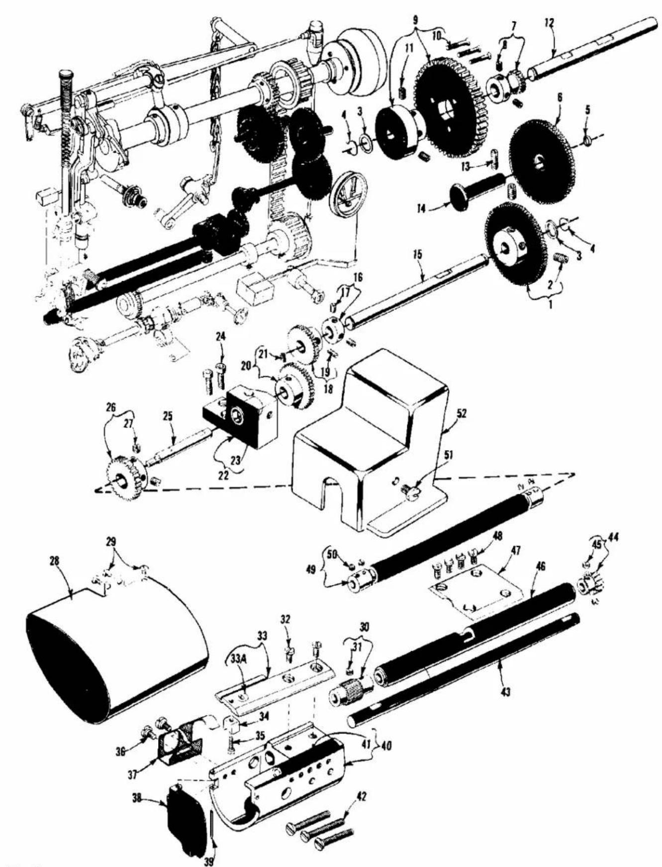
Technical diagram of a mechanical assembly with numbered components for identification and assembly reference.
| Ref. | Amt. | ||
| No. | Part No. | Description | Req. |
- 63962H Lower Reduction Gear 1
- 22894V Set Screw 2
- 39552C Thrust Washer 2
- 660-318 Truarc Ring 2
- 660-207 "O" Ring 1
- 63962L Middle Reduction Gear 1
- 63962K Upper Reduction Drive Dear 1
- 22878 Set Screw 2
- 63962J Upper Reduction Driven Gear 1
- 22525C Screw 3
- 22894J Set Screw 2
- 63962B Upper Reduction Gear Shaft 1
- 22597A Set Screw 1
- 63962A Middle Reduction Gear Stud 1
- 63962 Lower Reduction Gear Shaft 1
- 61248H Thrust Collar 1
- 531 Screw 2
*18. 63949-39 Upper Stitch Regulating Gear, for Styles 63900M, T 1
*- 63949-37 Upper Stitch Regulating Gear, for Styles 63900W, AE 1 - 18-500 Set Screw 1
*20. 63949-41 Lower Stitch Regulating Gear, for Styles 63900M, T 1
*- 63949-43 Lower Stitch Regulating Gear, for Styles 63900W, AE 1 - 18-500 Set Screw 1
- 63939 Top Feed Roller Drive Shaft Bushing Housing 1
- 63939H Top Feed Roller Drive Shaft Bushing 1
- 22652B-10 Screw 2
- 63939A Top Feed Roller Drive Shaft 1
- 61339D Lower Feed Roller Drive Gear 1
- 95 Set Screw 2
- 63982E Cloth Plate Extension, for Style 63900W, AE 1
-
22517B Screw, for Style 63900W, AE 3
-
thru 52. see following page.
* See page 13 "Gear Chart", for the gear combinations to produce stitches per inch, other than the ones indicated.
† Available as extra send and charge item.

text_image
Technical diagram of a mechanical assembly with numbered components for identification and assembly reference.
FEED ROLLER DRIVING PARTS (CONT.)
| Ref. | Amt. | ||
| No. | Part No. | Description | Req. |
-
thru 29. see preceding page.
-
63939P Lower Feed Roller, 24 teeth 1
†- 63939E Lower Feed Roller, medium diamond knurl ...... 1 - 22580 Set Screw 1
- 22569C Screw 2
- 63928 Throat Plate 1
33A. 63928A Needle Hole Insert, .080 inch dia. needle hole 1 - 61414E Bobbin Case Holder Positioning Finger 1
- 22653K-6 Screw 1
- 22875 Screw 2
- 63939N Lower Feed Roller Stripper 1
- 63982B Hook Housing Cover, for Styles 63900M, T 1
- 660-219 Roll Pin, for Styles 63900M, T 1
- 63941 Hook Shaft Bushing Housing 1
- 63941A Hook Shaft Bushing 1
- 22637R-96 Screw 3
- 63939B Lower Feed Roller Drive Shaft 1
- 51239E Lower Feed Roller Driven Gear 1
- 22580 Set Screw 2
- 63939S Lower Feed Drive Shaft Housing 1
- 63939F Clamp Plate 1
- 22569C Screw 4
- 63939J Top Feed Roller Flexible Drive Shaft 1
- 22650AA-2 Allen Set Screw, standard No. 8-32 national coarse thread, 1/8 inch long ..... 4
- 22517B Screw 1
- 63982D Feed Drive Gear Cover 1
† Available as extra send and charge item.

text_image
Technical diagram of mechanical components with numbered parts, including screws, bolts, and a cutting tool.BOBBIN WINDER AND MISCELLANEOUS ACCESSORIES
| Ref. | Amt. | ||
| No. | Part No. | Description | Req. |
- 61477M Bobbin Winder, complete 1
- 22846M-12 Wood Screw 2
- 61337N Trip Latch 1
*4. 21227BY Felt Assembly Adaptor 1 - 61212 Bobbin.... 1
*6. 21388AV Bearing Housing Puller 1 - 22653E-20 Clamp Screw 1
*8. 21227BZ Take-Up Eyelet Replacement Tool 1 - 22789B Thumb Screw 1
- 21665L Bell Crank Actuator Rod, for Styles 63900T, W, and AE 1
- 21663F Knee Press Plate Rod, for Style 63900M 1
- 21665C Rock Shaft Connecting Arm, for actuating folder actuator finger, for Style 63900M.... 1
- 21663C Knee Press Plate Rod, for Styles 63900T, W, and AE 1
14. 650AC-36 Screw, for table top 4
- 28604S Can of Oil, Spec. No. 175, 1 quart (not shown) 1
- 660-457 Dust Cover, (not shown) 1
* Not furnished with machine, but may be ordered separately as an extra send and charge.
# Not furnished with machine, but is a component of 1400D pedestal.
NUMERICAL INDEX OF PARTS
| Part No. | Page No. | Part No. | Page No. | Part No. | Page No. | Part No. | Page No. | Part No. | Page No. |
| 109 | 31 | 22716L | 41 | 51239E | 45 | 61467 | 33 | 63479E | 33 |
| 110-4 | 37 | 22716M | 41 | 51292C | 37 | 61468B | 33 | 63490B | 27 |
| 11635B | 27 | 22733D | 29 | 51773 | 35 | 61468D | 33 | 63491D | 33 |
| 12865 | 41 | 22738B | 37, 39 | 531 | 43 | 61468E | 33 | 63492 | 29 |
| 138 | 37 | 22738F | 39 | 54430E | 37 | 61468F | 33 | 63494A | 29 |
| 14077 | 35 | 22743 | 41 | 56393AA | 25 | 61470C | 29 | 63494B | 29 |
| 15872F | 33 | 22757D | 33 | 60038G | 35 | 61470D | 29 | 63494C | 25 |
| 18 | 35 | 22758B | 33 | 61210C | 41 | 61471A | 31 | 63494D | 27 |
| 18-500 | 43 | 22766 | 29 | 61212 | 47 | 61477M | 47 | 63494F | 27 |
| 20 | 35 | 22784E | 33 | 61212B | 41 | 61482J | 31 | 63494G | 27 |
| 20110 | 39 | 22784K | 25 | 61216 | 41 | 61490B | 25 | 63494K | 27 |
| 21227BY | 47 | 22789B | 47 | 61216N | 41 | 61490C | 25 | 63494M | 25 |
| 21227BZ | 47 | 22798A | 39 | 61248H | 43 | 61490D | 25 | 63496B | 41 |
| 21388AV | 47 | 22805 | 31 | 61255 | 33 | 61492E | 31 | 63903 | 39 |
| 21629 | 39 | 22815 | 25 | 61256G | 37 | 61492F | 31 | 63907A | 41 |
| 21662AE | 31 | 22817A | 33 | 61257G | 37 | 61492G | 31 | 63908 | 41 |
| 21663C | 47 | 22819 | 41 | 61292C | 31 | 61492H | 31 | 63913A | 41 |
| 21663F | 47 | 22839 | 33, 35 | 61293N | 27 | 61494D | 25 | 63914D | 41 |
| 21665C | 47 | 22845 | 37 | 61337N | 47 | 61494E | 25 | 63917C | 33 |
| 21665L | 47 | 22846M-12 | 47 | 61339D | 43 | 61494H | 27 | 63918A | 41 |
| 21680AX | 31 | 22863B | 29 | 61351C | 33, 41 | 61494L | 25 | 63920 | 37 |
| 21756G | 37 | 22868D | 41 | 61356 | 37 | 61494N | 25 | 63920A | 39 |
| 22504H | 35 | 22874F | 33 | 61360G | 33 | 61494T | 27 | 63920B1/2 | 39 |
| 22513D | 29 | 22875 | 39, 45 | 61392F14 | 31 | 61496C | 41 | 63920B3/8 | 39 |
| 22516 | 29 | 22878 | 43 | 61403 | 39 | 61496D | 41 | 63921 | 33 |
| 22517B | 31, 39, | 22882 | 37 | 61411B | 41 | 61496E | 41 | 63921BA | 33 |
| 22517B | 43, 45 | 22884 | 33 | 61414E | 45 | 61496F | 41 | 63928 | 45 |
| 22525C | 43 | 22890A | 33 | 61414F | 41 | 61496G | 41 | 63928A | 45 |
| 22539P | 29 | 22890C | 27 | 61415 | 41 | 61496J | 41 | 63930A | 39 |
| 22560G | 31 | 22894C | 33 | 61415A | 41 | 61496K | 41 | 63939 | 43 |
| 22562 | 31 | 22894E | 29, 35 | 61421G | 33 | 61496L | 41 | 63939A | 43 |
| 22562B | 33 | 22894J | 35, 43 | 61430BW | 39 | 61496M | 41 | 63939B | 45 |
| 22564 | 25, 27, 31 | 22894R | 41 | 61430BX | 39 | 61496N | 41 | 63939E | 45 |
| 22564M | 41 | 22894V | 33, 43 | 61430CL | 39 | 61496P | 27, 41 | 63939F | 45 |
| 22569B | 25 | 22894W | 33 | 61430R | 39 | 61496S | 27 | 63939H | 43 |
| 22569C | 45 | 230 | 37 | 61430V | 39 | 61496V | 41 | 63939J | 45 |
| 22569H | 41 | 23364AD | 39 | 61430X | 39 | 61541D-626 | 33 | 63939K | 37 |
| 22570 | 37 | 23364AG | 39 | 61432B | 27 | 61541D-627 | 33 | 63939N | 45 |
| 22570A | 29 | 23564 | 39 | 61439AG | 37 | 61982C | 29 | 63939P | 45 |
| 22571F | 31 | 23564A | 39 | 61439AM | 37 | 61982D | 29 | 63939R | 37 |
| 22574C | 33 | 23564C | 39 | 61439AN | 37 | 61984C | 35 | 63939S | 45 |
| 22580 | 45 | 23564D | 39 | 61439AP | 37 | 61985A | 35 | 63940 | 33 |
| 22585A | 37 | 23564E | 39 | 61439AR | 37 | 61985D | 35 | 63941 | 45 |
| 22593 | 39 | 23564G | 39 | 61440 | 41 | 61985F | 35 | 63941A | 45 |
| 22597A | 43 | 27-435BLK | 37 | 61441A | 27 | 61985G | 25 | 63949-37 | 43 |
| 22597E | 29 | 27-527BLK | 41 | 61444 | 41 | 61985H | 25 | 63949-39 | 43 |
| 22637R-96 | 45 | 28604S | 47 | 61451 | 33 | 61985J | 35 | 63949-41 | 43 |
| 22644K48 | 31 | 29126EL | 35 | 61451A | 33 | 63408 | 41 | 63949-43 | 43 |
| 22650AA-2 | 45 | 29474AH | 41 | 61451B | 33 | 63422 | 33 | 63949R | 25 |
| 22651CD-3 | 33 | 29474SA | 41 | 61451D-625 | 33 | 63432 | 41 | 63952C | 33 |
| 22652B-10 | 43 | 29474VA | 41 | 61451G | 33 | 63432C | 27 | 63953A | 25 |
| 22652D8 | 31 | 29475AR | 31 | 61455 | 33 | 63443 | 33 | 63957 | 37 |
| 22653D6 | 33 | 29486AB | 33 | 61458C | 37 | 63451 | 31 | 63957A | 25 |
| 22653E-20 | 47 | 35857R | 41 | 61458D | 37 | 63453 | 31 | 63958 | 37 |
| 22653K-6 | 45 | 39198D | 41 | 61458G | 37 | 63455 | 33 | 63959B | 37 |
| 22704 | 39 | 39552C | 43 | 61458H | 37 | 63457R | 37 | 63962 | 43 |
| 22711 | 39 | 421H | 33 | 61460 | 33 | 63466 | 33 | 63962A | 43 |
| 22712G | 33 | 51-159BLK | 25 | 61460A | 33 | 63470 | 29 | 63962B | 43 |
| 22716K | 41 | 51225W | 41 | 61460B | 33 | 63470A | 29 | 63962C | 27 |
NUMERICAL INDEX OF PARTS
Part No. Page No.
| 63962D | 27 |
| 63962E | 27 |
| 63962F | 27 |
| 63962G | 27 |
| 63962H | 43 |
| 63962J | 43 |
| 63962K | 43 |
| 63962L | 43 |
| 63970A | 29 |
| 63970B | 29 |
| 63971A | 31 |
| 63982 | 29 |
| 63982A | 29 |
| 63982B | 45 |
| 63982C | 31 |
| 63982D | 45 |
| 63982E | 43 |
| 63982F | 29 |
| 63984A | 35 |
| 63984C | 25 |
| 63985B | 35 |
| 63993B | 27 |
| 63993C | 25 |
| 63993D | 25 |
| 63993G | 33 |
| 63993H | 27 |
| 63994 | 25 |
| 63994C | 29 |
| 63996 | 31 |
| 650AC-36 | 47 |
| 652-16 | 31 |
| 652B20 | 33 |
| 660-204 | 31 |
| 660-207 | 43 |
| 660-219 | 45 |
| 660-219A | 29 |
| 660-219B | 37 |
| 660-219D | 41 |
| 660-221 | 27, 41 |
| 660-249 | 37 |
| 660-269 | 33 |
| 660-269A | 31 |
| 660-283A | 33 |
| 660-318 | 43 |
| 660-409 | 29 |
| 660-455 | 27 |
| 660-457 | 47 |
| 666-139 | 35 |
| 666-173 | 35 |
| 666-181 | 41 |
| 666-182 | 41 |
| 666-200 | 25 |
| 666-214 | 25 |
| 666-221 | 27 |
| 666-222 | 31 |
| 666-223 | 25 |
| 666-224 | 25 |
| 666-225 | 25 |
| 666-228 | 25 |
Part No. Page No.
| 6 6 6 - 2 3 4 | .... | 2 7 |
| 6 6 6 - 2 3 7 | .... | 2 7 |
| 6 6 6 - 2 3 8 | .... | 2 7 |
| 6 6 6 - 2 3 9 | .... | 2 7 |
| 6 6 6 - 2 4 0 | .... | 3 1 |
| 6 6 6 - 2 5 4 | .... | 2 5 |
| 6 9 5 8 | .... | 3 9 |
| 7 3 A | .... | 3 9 |
| 7 3 C | .... | 3 7 |
| 8 8 | .... | 3 9, 4 1 |
| 8 8 B | .... | 3 5, 3 7 |
| 8 9 | .... | 4 1 |
| 9 0 | .... | 2 9 |
| 9 0 7 | .... | 3 9 |
| 9 1 A | .... | 3 9 |
| 9 5 | .... | 3 5, 3 7, 4 3 |
| 9 9 3 7 | .... | 3 3 |
| H A 7 3 B | .... | 4 1 |
| H S 2 4 C | .... | 2 9 |
NOTES
NOTES

natural_image
Black-and-white globe projection grid showing continents and latitude/longitude lines (no text or labels)WORLDWIDE SALES AND SERVICE
Union Special Corporation maintains sales and service facilities throughout the world. These offices will aid you in the selection of the right sewing equipment for your particular operation. Union Special Corporation representatives and service technicians are factory trained and are able to serve your needs promptly and efficiently. Whatever your location, there is a qualified representative to serve you.
Corporate Office:
One Union Special Plaza Huntley, IL 60142 Phone: 847-669-5101 Fax: 847-669-4454
European Distribution Center:
Union Special GmbH Raiffeisenstrasse 3 D-71696 Möglingen, Germany Tel: 49·07141·247·0 Fax: 49·07141·247·100
Brussels, Belgium
Charlotte, N.C.
Hong Kong, China
Huntley, IL
Leicester, England
Lille, France
Miami, FL
Milan, Italy
Möglingen, Germany
Montreal, Quebec
Osaka, Japan
Santa Fe Springs, CA
Suwanee, GA
Wayne, NJ
Other Representatives throughout all parts of the world.

Union Special® INDUSTRIAL SEWING EQUIPMENT