52300F - Sewing machine Union Special - Free user manual and instructions
Find the device manual for free 52300F Union Special in PDF.

| Product Type | Sewing Machine |
| Brand | Union Special |
| Model | 52300F |
| Category | Industrial Sewing Machine |
| Dimensions (approx.) | 50 cm × 30 cm × 40 cm |
| Weight | 25 kg |
| Power Supply | 110-240 V, 50/60 Hz |
| Motor Power | 500 W |
| Stitch Type | Single Needle Lockstitch |
| Max Sewing Speed | 5000 SPM |
| Max Stitch Length | 5 mm |
| Needle System | 134-35 (Nm 140-230) |
| Material Compatibility | Medium to Heavy Fabrics |
| Lubrication | Automatic Oil System |
| Presser Foot Lift | Manual / Knee Lift |
| Safety Features | Needle Guard, Belt Guard |
| Maintenance | Regular Oil Application, Cleaning of Feed Dogs |
| Spare Parts Availability | Widely Available from Authorized Dealers |
| Warranty | 1 Year on Mechanical Parts |
Frequently Asked Questions - 52300F Union Special
User questions about 52300F Union Special
0 question about this device. Answer the ones you know or ask your own.
Ask a new question about this device
Download the instructions for your Sewing machine in PDF format for free! Find your manual 52300F - Union Special and take your electronic device back in hand. On this page are published all the documents necessary for the use of your device. 52300F by Union Special.
USER MANUAL 52300F Union Special
Union Special INDUSTRIAL SEWING EQUIPMENT
CATALOG NO. 117M
STYLES
52300B
52300D
52300E
52300F
STREAMLINED HIGH SPEED FOUR
THREAD MACHINES
Catalog No. 117 M
INSTRUCTIONS
FOR
ADJUSTING AND OPERATING
LIST OF PARTS
CLASS 52300
Four Thread Safety-Stitch Machines
Styles
52300 B
52300 D
52300 E
52300 F
First Edition
Copyright 1964
By
Union Special Corporation
Rights Reserved in All Countries
INDUSTRIAL SEWING MACHINES
CHICAGO
Printed in U.S.A.
November, 1978
IDENTIFICATION OF MACHINE
Each UNION SPECIAL machine is identified by a Style number which is stamped into the name plate on the machine. Style numbers are classified as standard and special. Standard Style numbers have one or more letters suffixed, but never contain the letter "Z". Example: "Style 52300 B". Special Style numbers contain the letter "Z". When only minor changes are made in a standard machine a "Z" is suffixed to the standard Style number. Example: "Style 52300 BZ".
Styles of machines similar in construction are grouped under a class number which differs from the style number, in that it contains no letters. Example: "52300".
APPLICATION OF CATALOG
This catalog applies specifically to the Standard Styles of machines as listed herein. It can also be applied with discretion to some Special Styles of machines in this class. Reference to direction, such as right, left, front, back, etc., are given from the operator's position while seated at the machine. Operating direction of handwheel is toward the operator.
STYLES OF MACHINES
Streamlined High Speed Flat Bed, Medium Throw, Vertical Trimmer, Front Disposal of Trimmings, Four Thread, Two Needles, Left Needle in Rear, Dual Stitch, 401 Double Locked Stitch on Left Needle, 503 Two Thread Overedge Stitch on Right Needle, Light Weight Presser Bar and Needle Bar Driving Mechanism, Single Reservoir Enclosed Automatic Lubricating System, Filter Type Oil Return Pump and Oil Siphon for Head.
52300 B For simultaneously seaming and overedging on sport shirts, ladies' blouses, street and house dresses, shoulder pads, coat linings, pillow cases, and similar operations on light to medium weight materials. Especially effective for handling wash and wear and other hard to handle materials. Seam Specification 401-503-SSa-2. Standard gauges Nos. 5-1/8, 8-1/8, 12-1/8 and 12-3/16.
52300 D Same as Style 52300 B, except fitted with combination end cover and apron type cloth plate. Standard gauges Nos. 5-1/8, 8-1/8, 12-1/8 and 12-3/16.
52300 E For simultaneously seaming and overedging on sport shirts, ladies' blouses, street and house dresses, shoulder pads, coat linings, pillow cases, and similar operations on light to medium weight materials. Seam Specification 401-503-SSa-2. Standard gauges Nos. 5-1/8, 8-1/8 and 12-3/16.
52300 F Same as Style 52300 E, except fitted with combination end cover and apron type cloth plate. Standard gauges Nos. 5-1/8, 8-1/8 and 12-3/16.
NEEDLES
Each UNION SPECIAL needle has both a type number and size number. The type number denotes the kind of shank, point, length, groove, finish and other details. The size number, stamped on the needle shank, denotes the largest diameter of blade measured in thousandths of an inch, midway between the shank and the eye. Collectively, the type number and the size number is the complete symbol which is given on the label of all needles packaged and sold by Union Special.
Standard needle for all Styles in Class 52300 is Type 108 GHS. It has a round shank, round point, extra short, double groove, struck groove, ball eye, spotted, ball point, chromium plated - available in sizes 070/027, 075/029, 080/032, 090/036, 100/040, 110/044, 125/049.
NEEDLES (Continued)
To have needle orders promptly and accurately filled, an empty package, a sample needle, or the type and size number should be forwarded. Use description on label. A complete order would read: "1000 Needles, Type 108 GHS, Size 080/032".
Selection of the proper needle size should be determined by size of thread used. Thread should pass freely through the needle eye in order to produce a good stitch formation.
ORDERING OF REPAIR PARTS
ILLUSTRATIONS
The arrangement of this catalog is to facilitate easy and accurate ordering of Class 52300 replacement parts.
Exploded view plates cover the Standard Styles listed in this catalog. Each plate presents a sector of the machine, parts being aligned as in their assembled position. Small keyline views show by a blackened area exactly where the parts being discussed fit in the assembled machine. On the page opposite the illustration will be found a listing of the parts with their part numbers, descriptions and the number of pieces required in the particular view being shown.
Numbers in the first column are reference numbers only, and merely indicate the position of the part in the illustration. Reference numbers should never be used in ordering parts. Always use the part number listed in the second column. Each exploded view plate carries a reference number for each part for sale.
Sub-assemblies, which are sold complete, or by separate part, are in a bracket or a solid line box on the exploded view plate. Component parts of sub-assemblies, which can be furnished for repairs, are indicated by indenting their descriptions under the description of the main sub-assembly. Example:
| 3 | 29476 KB | Crankshaft Assembly, .910 inch throw | 1 |
| 4 | 51216 M | Needle Bearing | 28 |
It will be noted in the above example that the bearing and crankshaft are not listed. The reason is that replacement of these parts individually is not recommended, so the complete sub-assembly should be ordered.
In those cases where a part is common to all of the machines covered by this catalog, no specific usage will be mentioned in the description. However, when the parts for the various machines are not the same, the specific usage will be mentioned in the description, and if necessary, the difference will be shown in the illustration.
At the back of the book will be found a numerical index of all the parts shown in this book. This will facilitate locating the illustration and description when only the part number is known.
IDENTIFYING PARTS
Where the construction permits, each part is stamped with its part number. On some of the smaller parts, and on those where the construction does not permit, an identification letter is stamped in to distinguish the part from similar ones.
Part numbers represent the same part, regardless of catalog in which they appear.
IMPORTANT! ON ALL ORDERS, PLEASE INCLUDE PART NAME AND STYLE OF MACHINE FOR WHICH PART IS ORDERED.
USE GENUINE NEEDLES AND REPAIR PARTS
Success in the operation of these machines can be secured only with genuine UNION SPECIAL Needles and Repair Parts as furnished by the Union Special Corporation, its subsidiaries and authorized distributors. They are designed according to the most approved scientific principles, and are made with utmost precision. Maximum efficiency and durability are assured.
Genuine needles are packaged with lables marked Union Special®. Genuine repair parts are stamped with the Union Special trademark, U S Emblem. Each trademark is your guarantee of the highest quality in materials and workmanship.
TERMS
Prices are strictly net cash and are subject to change without notice. All shipments are forwarded f.o.b. shipping point. Parcel Post shipments are insured unless otherwise directed. A charge is made to cover the postage and insurance.
text_image
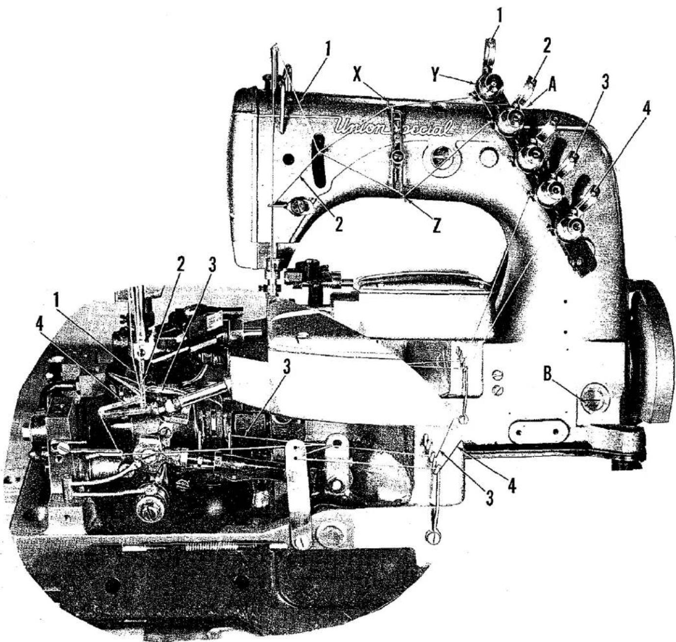
Union Special 1 2 3 4 5 6 7 8 9 10 11 12 13 14 15 16 17 18 19 20 21 22 23 24 25 26 27 28 29 30 31 32 33 34 35 36 37 38 39 40 41 42 43 44 45 46 47 48 49 50OILING AND THREADING DIAGRAM FOR CLASS 52300 MACHINES
The oil has been drained from the machine before shipping and the reservoir must be filled before beginning to operate. Use a straight mineral oil with a Saybolt viscosity of 90 to 125 seconds at 100^ Fahrenheit.
Oil is filled at the spring cap in the top cover (A) and the oil level is checked at the sight gauge (B) on the front of the machine. The oil level should be maintained between the red lines on the gauge. The capacity of the oil reservoir is 12 ounces.
The machine is automatically lubricated and no oiling, other than keeping the main reservoir filled is necessary.
A daily check before the morning start should be made and oil added if required. Oil which has gone through the machine is filtered and pumped back into the main reservoir, making too frequent oilings unnecessary. Excessive oil in the main reservoir may be drained at the plug screw in the main frame directly under the handwheel.
The above picture shows the manner in which the 52300 Styles covered in this catalog are threaded. The looper threading has been enlarged for clarity.
SELF-PRIMING HEAD OIL SIPHON
Class 52300 machines are equipped with a self-priming head oil siphon. When the machine is started, oil splashes on the priming cup felts, filters through the felts, and trickles down the vertical oil tube, thus, priming the siphon. Once the prime is established, it is maintained, unless the felts are removed. The siphon operates twenty-four hours a day, removing oil at the rate of six to twelve drops per minute, which of course, far exceeds the rate at which oil collects in the head.

text_image
51294 M Long Tube 51294 R Screw 7947 Nut 51294 P Clamp 666-214 Lint Filter 22513 Screw (In Machine) 35731 A Guide Plate (In Machine) 666-201 Soft Top Felt 51294 U Oil Siphon 21212 Collar 22729 A Screw 21657 X Tens. Release Lever Bushing (In Bed)INSTALLING AND MAINTENANCE OF OIL SIPHON
A newly installed siphon starts its action within three to five minutes after the machine is operating. However, it may be twenty minutes or so before all the air is removed from the line and the siphon is in full operation. Within an hour, there is a distinct drop in oil level in the head sump.
The felts in the priming cup are designed for a specific purpose. The bottom felt, 666-209, is thin and relatively dense, to meter the flow of priming oil and to prevent the entrance of air. The softer top felt, 666-201, is a filter to prevent the clogging of the metering felt. This felt, at the intake of the siphon, keeps the siphon clear of lint, and prevents the entrance of air at that point. For the best initial self-priming condition, the felts of the siphon should be dry. In this condition, it is difficult for air to be trapped between the felts or in the top soft felt itself.
However, if for some reason the priming cup felts had been oiled before installing, the siphon may fail because air is trapped between the felts or in the soft top felt. As a precaution, remove the soft felt from the cup. Then, while squeezing the felt between the fingers, saturate it well with oil. In other words, squeeze out the air and replace it with oil. Then, completely fill the cup with oil, and push or twist the soft felt down into cup so that it definitely contacts the harder thin felt. This precaution prevents the trapping of air, and no trouble should be experienced when starting the siphon.
If you want to be doubly sure that the siphon is functioning correctly, on a machine in operation, apply a certain amount of oil in the sump around the felt in the head. Before doing this, be certain that this felt has been saturated in the same manner as explained for the soft felt in the top of the siphon cup. When this is done, the siphoning action will begin, and the oil will be removed as explained.
INSTRUCTIONS FOR MECHANICS
NEEDLE LEVER STUD SETTING
Observe the location of the needle lever stud (A, Fig. 1). The head of the needle lever stud is marked with an arrow and the word "UP". These studs are set correctly

text_image
C A BFig. 1
when the arrow points vertically up. Also check the position of the needle lever bearing oiler (B) inside the arm casting, which lubricates the needle lever stud. Make sure it is tilted downwardly and that its delivery end (C) contacts the inside wall of the bed casting at the back, just above the notch of the needle lever shaft stop collar. Do not allow the oil tube to rest on the needle lever.
OILING SYSTEM
Clean machine thoroughly. Fill oiling system to the first red line of oil gauge on the front of the machine, and oil all bearings. Run machine slowly for a minute to allow oil wicks to carry oil to the bearings. Then recheck oil in oiling system and run machine for five minutes at 5000 R.P.M. Wipe up any surplus oil, particularly around the take-up. Inspect siphon and head felt for proper function, and
all plug screws for leakage.
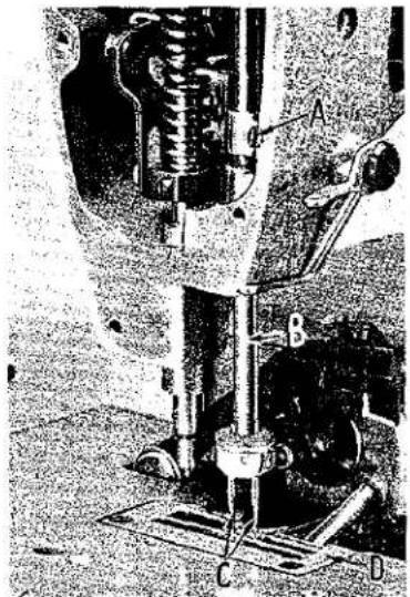
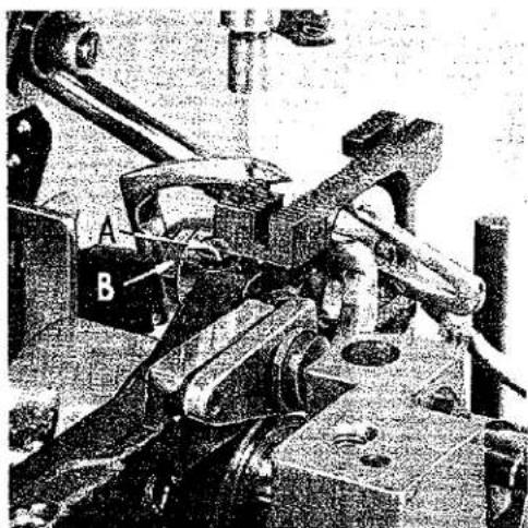
NEEDLE BAR ALIGNMENT
Align needle bar by using a new set of needles Type 108 GS, of a size to meet the requirements. Loosen screw (A, Fig. 2) and turn needle bar (B) so that the needles (C) center in the front end of the needle slots in the throat plate (D), and retighten screw. The height of the needle bar is set so that the top of the rear needle's eye is 1/32 inch below the back looper, when point of looper, moving to the left, is even with the left side of this needle.
SETTING THE BACK LOOPER (401 Stitch)
Insert the rear needle (A, Fig. 3), Type 108 GS, size as specified and insert the 401 stitch looper (B) in the looper rocker (C), and tighten screw (D). Rotate handwheel in operating direction until back looper is in the extreme right position. The looper should be set so that its point is 1/8 inch from the center of the back needle, as in Fig. 3. Looper gauge No. 21225-1/8 can be used advantageously in making this adjustment. If adjustment is needed, loosen nut (A, Fig. 4) (it has a left hand thread) and also loosen nut on right end of connecting rod (B), turn connecting rod forward or backward to obtain 1/8 inch, and retighten both nuts.
natural_image
Mechanical assembly diagram showing a spring-loaded clamping device with labeled components A, B, C, D (no readable text or symbols)Fig. 2
The looper is set correctly in line with the feed when the looper, moving to the left, passes the back of the rear needle as close as possible without contacting or approximately .002 inch clearance. If adjustment is needed, loosen screw (C) and move looper toward or away from needle as required, and retighten screw.
SETTING THE FRONT LOOPER (503 Stitch)
Insert the front needle (E, Fig. 3) and also insert the 503 stitch looper (F) in the lower looper bar (G), and tighten nut (H). Rotate handwheel in operating direction until front looper is in the extreme left position. The looper should be set so that its point is 1/8 inch from the center of the front needle, as in Fig. 3.
Looper gauge No. 21225-1/8 can be used advantageously in making this adjustment. If adjustment is needed, loosen nut (H) and slide looper in or out of its holder and retighten nut.
The looper is set correctly in line with the feed when the looper, moving to the right, passes the back of the front needle as close as possible without contacting or approximately .002 inch clearance. If adjustment is needed, loosen nut (H) and rotate looper toward or away from needle as required, and retighten nut.
Set the needle guard (J) on the front looper and swing the needle guard out so that the guard contacts the needle, but does not deflect it. When the guard is properly set, the clearance between the looper and needle has not been changed, and the looper will not pick the needle when the looper is moving to the right and the needle is held against the needle guard.

text_image
A E G 1/8 B 8 H J C DFig. 3
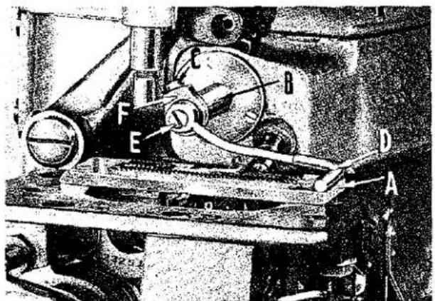
SYNCHRONIZING LOOPER AND NEEDLE MOTIONS
With the back looper (B, Fig. 3) in the looper rocker (C), turn the handwheel in the operating direction until the looper moves to the left and its point is even with left side of the needle (A). Note the height of the eye of the needle with respect to the looper point, then turn the handwheel in the reverse direction until the looper point again moves to the left and is even with the left side of the needle.
text_image
Technical diagram of a mechanical device with labeled parts A through H, showing internal components and structural details.Fig. 4
SYNCHRONIZING LOOPER AND NEEDLE MOTIONS (continued)
If the motions are synchronized, the height of the eye of the needle with respect to the looper point will be the same. A variation of .005 inch is allowable. If the distance from the eye of the needle to the point of the looper is longest when the pulley is turned in operating direction, move the looper drive lever shaft synchronizing stud (D, Fig. 4) to the rear. Moving it in opposite direction acts the reverse.
text_image
Technical diagram of a mechanical device with labeled parts A, B, C, D, E, FFig. 5
Moving of the looper drive lever shaft synchronizing stud is accomplished as follows: Loosen clamp screw (E, Fig. 4) of looper drive lever.
To move stud to the rear (away from operator), a light tap with a small hammer, directly on the stud, is all that is required.
To move stud forward (toward operator), remove oil reservoir back cover and then a light tap on the looper drive lever rocker shaft, toward the operator, is all that is required.
Then, using the looper drive lever to take up the end play between the looper
drive lever rocker shaft and its synchronizing stud, retighten clamp screw (E).
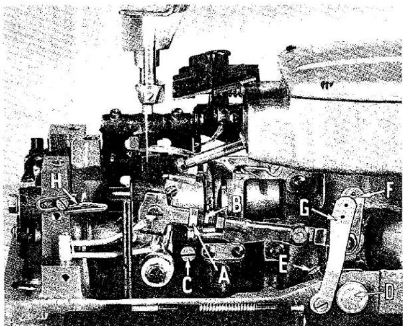
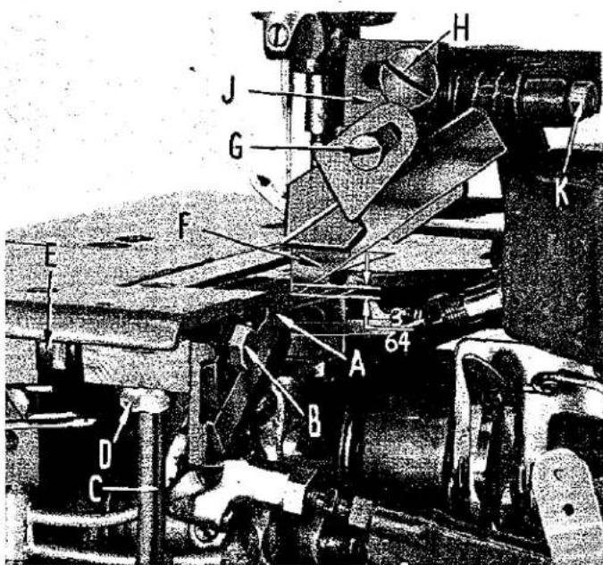
SETTING THE SPREADER
Mount throat plate (A, Fig. 5) on machine. Turn handwheel in operating direction until spreader bar (B) is in the extreme left position. Loosen collar screw (C) and insert spreader gauge 21227 BX (D) in spreader bar and line up the front edge of the spreader gauge with the front edge of the throat plate and tighten clamp screw (E). Move spreader holding block (F) in or out of spreader bar until the left edge of the spreader gauge is in line with the left edge of the throat plate. Tighten collar screw (C).
Remove gauge and insert the spreader. Rotate handwheel to be sure that spreader does not touch the lower looper or the needle at any time.
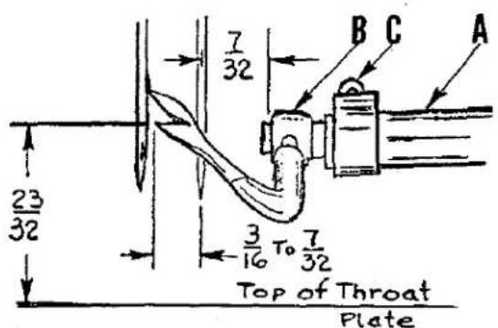
If spreader gauge is not available to set the spreader, turn the handwheel in the operating direction until the spreader bar (A, Fig. 6) is in the extreme left position. Set the spreader holder (B) in the spreader bar so the left end of the holder is 7/32 inch to the right of the center of the right hand needle (Fig. 6), and tighten collar screw (C). Looper gauge 21225-7/32 can be used for this setting. DO NOT CHANGE THIS LATERAL SETTING OF THE HOLDER.
text_image
23/32 7/32 B C A 3/16 To 7/32 Top of Throat PlateFig. 6
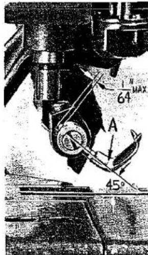
Preliminary Setting: Position the holder so the hole is approximately 45^ to the throat plate (Fig. 6A). Insert the spreader (A) in the holder so its shank extends NOT more than 1/64 inch beyond the holder (Fig. 6A).
SETTING THE SPREADER (continued)
With the spreader in this position, rotate the spreader about its shank so the point closest to the operator is between 3/16 and 7/32 inch to the left of the center of the needle and approximately 23/32 inch above the throat plate (Fig. 6). Turn the handwheel in the operating direction and check clearance between the bottom point of the spreader and the lower looper. The spreader point should cross the top of the looper to the left as close as possible to the eye and to the back of the looper without touching it.
The spreader, in its travel, should NOT touch the lower looper or the needle at any time. Slight adjustments to the preliminary setting may be necessary to effect this clearance.
Adjustments: (1) Rotating the spreader holder clockwise will cause the spreader point to cross the lower looper farther to the left of the eye of the looper, increasing the clearance between the needle and the back of the spreader. (2) Pulling the spreader farther out of the holder increases the clearance between the needle and the back of the spreader, and reduces the clearance between the spreader point and the back of the looper. (3) With the spreader in the extreme left position, rotating the spreader counterclockwise about its shank decreases the clearance slightly between the needle and the back of the spreader and increases the clearance between the back of the looper and the point of the spreader.
text_image
1 N 64 MAX A 45°Fig. 6A
text_image
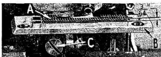
A C B Ø1 3/64Fig. 7
hold feed dog in position.
SETTING THE FEED DOG
Set the feed dog (A, Fig. 7) in the throat plate (B) so there is equal clearance on all sides and that the tips of the teeth are parallel with and project 3/64 inch above the throat plate at high point of travel. Adjust the supporting screw (A, Fig. 8) under the feed dog to maintain this setting. Screw (C, Fig. 7) is used to
If feed dog teeth are not parallel with the throat plate, loosen nut (B, Fig. 8) and turn screw (A, Fig. 9) clockwise to lower the front teeth, and counterclockwise to raise the front teeth. Retighten nut when feed dog is set properly.
Should it be necessary to move the feed dog to the left or right, loosen screws (A, Fig. 10) which hold the feed rocker (B) onto the feed rocker shaft (C), and move feed rocker to desired position and retighten screws. Make sure that the feed rocker arm (D) does not bind after making this adjustment.
Should it be necessary to move the feed dog forward or backward, loosen screws (E) which clamp the feed rocker arm to the feed rocker and move the feed rocker forward or backward as needed, and retighten screws.
natural_image
Mechanical assembly with labeled parts A and B, no visible text or symbols beyond labelsFig. 8
SETTING THE FEED DOG (continued)
With an average stitch length setting, equalize the travel of the feed dog so that at both ends of its travel, it is equidistant from the ends of the throat plate slot. Make this adjustment the same as described in paragraph 4.
CHANGING STITCH LENGTH

natural_image
Close-up of mechanical components with no visible text or symbolsFig. 9
Set the stitch to required length. This is accomplished by loosening the lock nut (F, Fig. 10) (it has a left hand thread) on the end of the stitch regulating stud and turning the stitch adjusting screw (G) located under the left end of the cloth plate in the head of the main shaft. Turning the screw clockwise shortens the stitch, and turning the screw counterclockwise lengthens the stitch.
Note: Any change in the stitch length will require a change in the rear needle guard setting.
SETTING THE REAR NEEDLE GUARD
Set the needle guard (A, Fig. 11) horizontally so that it barely contacts the needle (B). It should be set as low as possible, yet have its vertical face remain in contact with the needle until the point of the looper (C), moving to the left, is even with the needle and the latter is ascending on the left side. To move needle guard forward or backward, merely loosen screw (D), move needle guard as required, and retighten screw. To raise or lower needle guard, loosen screw (D), and turn screw (E) clockwise to lower needle guard, and counterclockwise to raise needle guard. Retighten screw (D) after guard is set properly.

text_image
Technical diagram of a mechanical device with labeled parts A through G, likely an industrial machine or robotic arm.Fig. 10
THREADING
Draw looper and needle threads into machine and start operating on a piece of fabric. Refer to threading diagram on Page 6, for manner of threading these machines.
THREAD TENSIONS
The tension on the needle threads should be only sufficient to produce uniform stitches. The tension on the looper threads should be only sufficient to steady it. KEEP TENSIONS LOW - THIS IS A MUST!
PRESSER FOOT PRESSURE
Regulate the presser spring regulating screw located directly behind the needle bar on the head of the machine so that it exerts only enough pressure on the presser foot to feed the work uniformly. See that the presser foot hinges freely and that it is in alignment with the throat plate.
text_image
D E C BFig. 11
SETTING THE NEEDLE THREAD EYELETS
There are two frame needle thread eyelets that have to be set. The 401 stitch eyelet (X, Page 6) is set correctly when it is as high as possible and there is no thread pulled through the thread tension (Y) as the needle descends. The 503 stitch eyelet (Z), which is facing downward, is used in setting the position of the purl. Raising the eyelet causes less thread to be drawn and moves the purl toward the underside of the cloth. Lowering the eyelet allows more thread to be drawn and thus causes the purl to move toward the top of the material being sewn.
SETTING THE LOOPER THREAD TAKE-UP AND EYELETS
text_image
H J G F E K 3.4 64 A B D CFig. 12
The 503 looper thread take-up (F, Fig. 4) should be positioned approximately on the center line of the looper drive lever as per Fig. 4. Eyelets (G, and H, Fig. 4) are positioned correctly when the lower looper thread is taut as the spreader reaches the left end of its travel.
Note: Only about 1/3 of the looper thread required to form a stitch is drawn through the tension during the travel toward the left end. No thread should be pulled through the thread tension as the spreader reaches the extreme left of its stroke.
To control the ratio of thread pulled during the leftward movement, use the thread take-up eyelet (G, Fig. 4).
SETTING THE LOOPER THREAD TAKE-UP AND EYELETS (continued)
Moving this eyelet to the left causes more looper thread to be drawn on the left hand stroke of the spreader, and moving it to the right causes less looper thread to be drawn. Moving this eyelet to the right or left also affects the drawing of the looper thread at the extreme left position. To readjust for this condition, move the eyelet (H, Fig. 4) to the right to reduce the thread drawn or to the left to reduce the amount of slack. The two eyelets (F and G) are to be adjusted in conjunction with each other so that the following conditions are met: (1) 1/3 of the looper thread is drawn during the left stroke of spreader, and (2) No looper thread is drawn at the extreme end of stroke.

text_image
A B C DFig. 13
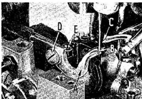
SETTING THE LOWER KNIFE
The lower knife (A, Fig. 12) should be set so that its cutting edge is even with the top surface of the throat plate. Use a steel scale to get a parallel setting and when knife is at the right height, tighten screw (B). To move the lower knife either to the left or to the right, loosen nut on the bottom of support rod (C), turn rod in a clockwise direction until it clears knife holder block screw (D), and then loosen the screw. Turn screw (E) in a clockwise direction to move knife to the left or in a counterclockwise direction to move it to the right. Once the knife has been set to the required trimming line, tighten screw (D), turn support rod (C) counterclockwise until it stops against screw (D) and then tighten nut on the bottom of the support rod.
SETTING THE UPPER KNIFE
Turn the handwheel in operating direction until the upper knife arm is in its lowest position. The cutting edge of the upper knife (F, Fig. 12) should overlap the cutting edge of the lower knife by about 1/64 inch. Loosen clamp screw (G) to adjust upper knife. Move knife to the left to lower it or to the right to raise it. Tighten clamp screw. To set the spring tension on the upper knife, loosen screw (H), move knife holder block (J) to the left, and while holding it in this position, push knife guide collar shaft (K) to the right to increase spring tension on upper knife and tighten screw (H). Turn handwheel in operating direction until the upper knife is at its highest point of travel, and at this point, the pilot of the upper knife should overlap the lower knife about 3/64 inch (Fig. 12).
Note: Never let the cutting edge of the upper knife descend move than 1/64 inch below the cutting edge of the lower knife, as it will damage the front cover. Also, never let the pilot of the upper knife move past the cutting edge of the lower knife on its upward travel. If this should happen, a new setting of the upper knife must be made.

natural_image
Mechanical assembly diagram showing components labeled A and B, with no visible text or symbols beyond labelsFig. 14
The correct angle of the knife cutting edges can be maintained only by resharpening them in a special knife grinder No. 52998 N, which can be furnished at an extra charge.
SETTING THE UPPER KNIFE (continued)
The upper knife is adjustable for either a high or low knife lift. All standard machines are sent from the factory as low knife lift machines. To change the machines to a high knife lift, loosen screw (A, Fig. 13) and then remove link pin (B) from the bottom hole (C) to top hole and tighten screw (D). When this setting is changed, readjustment of upper knife will have to be made, as described earlier.
SETTING PRESSER BAR STOP COLLAR
Set the presser bar stop collar (A, Fig. 14) so the presser foot cannot be raised or tilted into the path of the spreader (B).

text_image
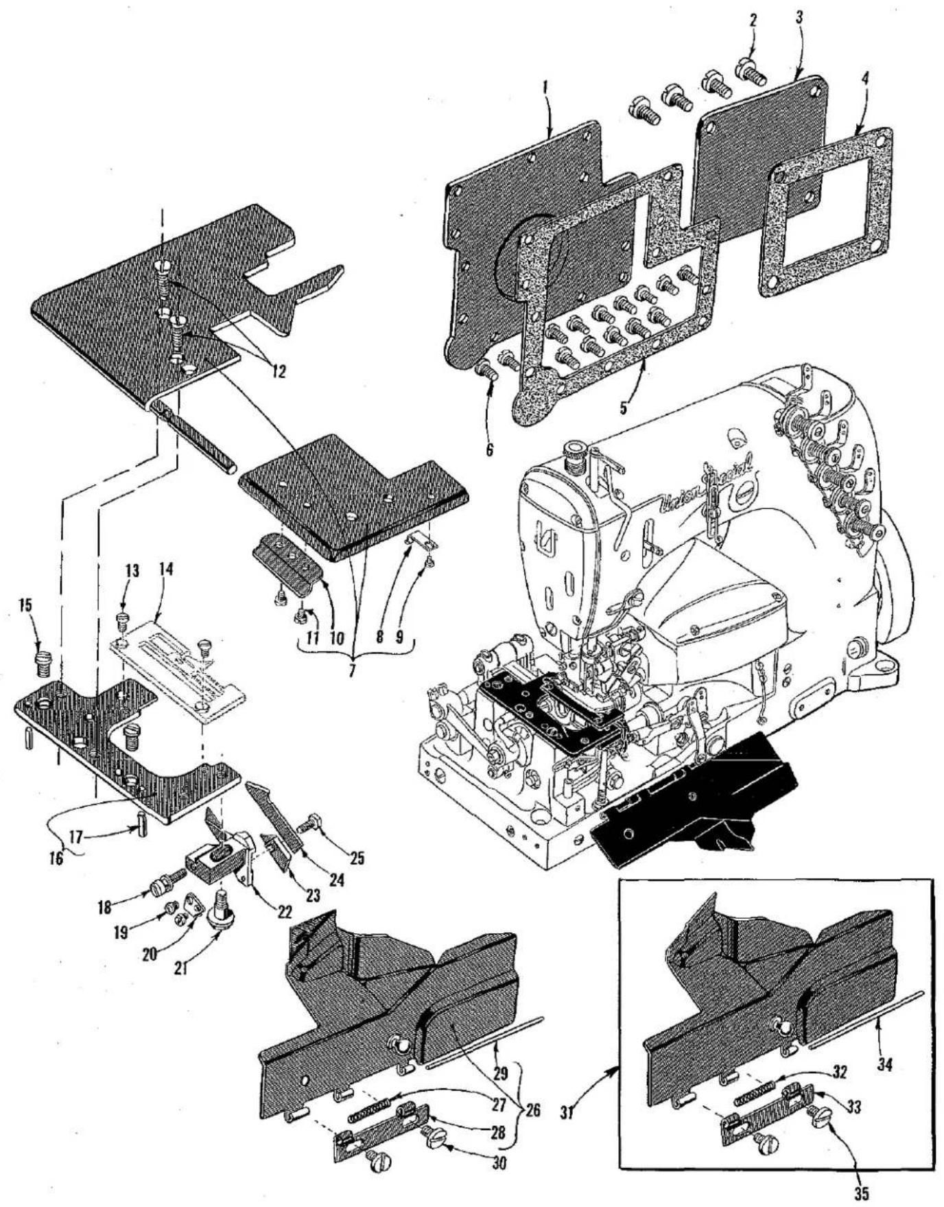
Technical diagram of Union Special device with numbered parts and exploded view, showing internal components and assembly relationships.MAIN FRAME, CAST-OFF PLATE AND MISCELLANEOUS COVERS
| Ref No. | Part No. | Description | Amt. Req. |
| 1 | 52385 | Combination End Cover and Cloth Plate, for Styles 52300 D, F | 1 |
| 2 | 22848 | Screw | 4 |
| 3 | 57885 B | End Cover Hinge, rear | 1 |
| 4 | 57885 | End Cover Hinge, front | 1 |
| 5 | 22711 | Screw | 1 |
| 6 | 52885 L | End Cover Spring | 1 |
| 7 | 22799 M | Screw | 1 |
| 8 | 52882 AD | Crank Chamber Cover | 1 |
| 9 | 39582 L | Oil Cap | 1 |
| 10 | 52882 AC | Oil Cap Torsion Spring | 1 |
| 11 | 50-789 Blk. | Oil Cap Hinge Pin | 1 |
| 12 | 52882 AA | Drip Plate | 1 |
| 13 | 90 | Screw | 2 |
| 14 | 22541 B | Screw | 3 |
| 15 | 52882 P | Gasket | 1 |
| 16 | 90 | Screw | 2 |
| 17 | 56382 AC | Needle Lever Bearing Oiler Assembly | 1 |
| 18 | 719 | Screw | 2 |
| 19 | 51270 B | Needle Thread Take-up Wire | 1 |
| 20 | 95 | Screw | 1 |
| 21 | 51294 R | Screw | 1 |
| 22 | 35731 A | Presser Bar Connection Guide Plate | 2 |
| 23 | 51294 P | Oil Tube Clamp | 1 |
| 24 | 7947 | Nut | 1 |
| 25 | 22513 | Screw | 3 |
| 26 | 51282 Z | Gasket | 1 |
| 27 | 22569 B | Screw | 5 |
| 28 | 51282 Y | Head Cover | 1 |
| 29 | 22542 | Screw | 1 |
| 30 | 52882 W | Washer | 1 |
| 31 | 51282 AC | Sound Insulator, felt | 1 |
| 32 | 98 A | Screw | 1 |
| 33 | 52358 D | Looper Thread Eyelet, left | 1 |
| 34 | 52357 A | Cast-off Support Plate | 1 |
| 35 | 52804 A | Cast-off Plate | 1 |
| 36 | 28 | Screw | 2 |
| 37 | 50-216 Blk. | Pin | 2 |
| 38 | 21657 E | Washer | 1 |
| 39 | 22528 | Screw | 1 |
| 40 | 52 A | Eyelet | 1 |
| 41 | 87 U | Screw | 1 |
| 42 | 52358 C | Looper Thread Eyelet, right | 1 |
| 43 | 98 A | Screw | 1 |
| 44 | 52942 Y | Looper Drive Lever Shaft Synchronizing Stud | 1 |
| 45 | 52958 G | Frame Thread Eyelet | 1 |
| 46 | 98 A | Screw | 1 |
| 47 | BB21375 AH | Belt Guard | 1 |
| 48 | 93 | Screw | 2 |
| 49 | 22848 | Screw | 1 |
| 50 | 20 | Washer | 1 |
| 51 | 539 | Frame Thread Eyelet | 2 |
| 52 | 22889 A | Adaptor Plug Screw | 1 |
| 53 | 22517 B | Screw | 1 |
| 54 | 52358 A | Needle Thread Guide | 1 |
| 55 | 52358 E | Needle Thread Wire | 1 |
text_image
Technical diagram of a mechanical assembly with numbered parts, likely an electrical or mechanical component, showing exploded and assembled views.CLOTH PLATE, MISCELLANEOUS COVERS AND LOWER KNIFE PARTS
| Ref.No. | PartNo. | Description | Amt.Req. |
| 1 | 52382 | Oil Reservoir Back Cover | 1 |
| 2 | 22548 | Screw | 4 |
| 3 | 52882 AE | Crank Chamber Cover | 1 |
| 4 | 52882 U | Gasket | 1 |
| 5 | 52382 A | Gasket | 1 |
| 6 | 376 A | Screw | 14 |
| 7 | 52301 | Cloth Plate, for Styles 52300 B, E | 1 |
| 8 | 52381 C | Latch Spring | 1 |
| 9 | 604 | Screw | 1 |
| 10 | 52381 B | Hinge Bar Clamp | 1 |
| 11 | 28 | Screw | 2 |
| 12 | 80 | Screw | 2 |
| 13 | 87 | Screw | 2 |
| 14 | Throat Plate (See Page 35) | 1 | |
| *15 | 22839 | Screw | 2 |
| 16 | 52380 B | Throat Plate Support | 1 |
| 17 | 51280 J | Dowel Pin | 2 |
| 18 | 22568 | Screw | 1 |
| 19 | 25 B | Screw | 2 |
| 20 | 52378 C | Chip Guard Latch Spring | 1 |
| 21 | 35766 | Screw | 1 |
| 22 | 52350 B | Lower Knife Holder | 1 |
| 23 | 52350 A | Lower Knife Clamp Plate | 1 |
| 24 | 52349 | Lower Knife | 1 |
| 25 | 22588 A | Screw | 1 |
| 26 | 52378 E | Chip Guard, for Styles 52300 E, F | 1 |
| 27 | 39158 U | Spring | 1 |
| 28 | 39158 G | Front Cover Hinge | 1 |
| 29 | 51278 G | Hinge Pin | 1 |
| 30 | 25 S | Screw | 2 |
| 31 | 52378 D | Chip Guard, for Styles 52300 B, D | 1 |
| 32 | 39158 U | Spring | 1 |
| 33 | 39158 G | Front Cover Hinge | 1 |
| 34 | 51278 G | Hinge Pin | 1 |
| 35 | 25 S | Screw | 2 |
* NOTE: Use countersunk head screw No. 80 for old Style 52380 B.

text_image
Technical diagram of a mechanical device with numbered components and exploded view, including parts like gears, springs, and housing.| Ref. No. | Part No. | Description | Amt. Req. |
| 1 | 51294 U | Oil Siphon Assembly | 1 |
| 2 | 51294 K | Clamp, upper | 1 |
| 3 | 22729 B | Screw | 1 |
| 4 | 666-209 | Siphon Cup Disc Felt | 1 |
| 5 | 666-201 | Feit Plug | 1 |
| 6 | 52883 R | Presser Foot Lifter Lever Bushing | 1 |
| 7 | 51294 Z | Oil Tube Connection | 1 |
| 7A | 21212 | Oil Siphon Connection Locking Ring | 1 |
| 8 | 51254 C | Needle Bar Bushing, upper | 1 |
| 9 | 52393 J | Oil Tube, for knife drive eccentric | 1 |
| 10 | 666-208 | Oil Wick | 1 |
| 11 | 52994 AC | Oil Tube, for feed lift and looper avoid eccentric | 1 |
| 12 | 90 | Screw | 2 |
| 13 | 52894 AB | Oil Tube Holder | 2 |
| 14 | 51257 AA | Presser Bar Bushing, lower | 1 |
| 15 | 51254 D | Needle Bar Bushing, lower | 1 |
| 16 | 51294 M | Oil Siphon Tube | 1 |
| 17 | 666-214 | Felt Lint Filter | 1 |
| 18 | 21657 X | Tension Release Shaft Bushing | 1 |
| 19 | 22729 A | Screw | 1 |
| 20 | 52891 B | Crankshaft Bushing Housing, including bushing | 1 |
| 21 | 52390 | Main Shaft Bushing, inner right | 1 |
| 22 | 51290 T | Main Shaft Bushing, middle | 1 |
| 23 | 52942 X | Looper Drive Lever Shaft Bushing, rear | 1 |
| 24 | 52936 | Feed Rocker Shaft Bushing | 2 |
| 25 | 660-136 | Oil Tube, for feed crank link | 1 |
| 26 | 258 A | Nut- | 1 |
| 27 | 52890 C | Main Shaft Bushing, left | 1 |
| 28 | 52944 T | Looper Rocker Shaft Bushing, left | 1 |
| 29 | 52894 AK | Oil Tube, for looper rocker and left ball joint | 1 |
| 30 | 22560 B | Screw | 1 |
| 31 | 258 | Nut- | 1 |
| 32 | 51280 E | Lower Knife Support Bed Pin | 1 |
| 33 | 51493 BK | Lint Filter Screen | 1 |
| 34 | 52944 U | Looper Rocker Shaft Bushing, right | 1 |
| 35 | 52942 W | Looper Drive Lever Shaft Bushing, front | 1 |
| 36 | 22596 | Screw, for oil pump assembly | 2 |
| 37 | 50-648 Blk. | Lucite Oil Gauge | 1 |
| 38 | 52393 | Oil Pump Assembly | 1 |
| 39 | 52393 K | Oil Pump Driven Gear | 1 |
| 40 | 52393 A | Oil Pump Housing | 1 |
| 41 | 51493 E | Driving Shaft Gear | 2 |
| 42 | 52393 D | Oil Pump Cover | 1 |
| 43 | 61341 J | Washer | 1 |
| 44 | 52393 L | Oil Pump Gear Stud | 1 |
| 45 | 22585 | Screw | 3 |
| 46 | 643-127 Blk. | Gasket | 1 |
| 47 | 52393 H | Oil Pump Intake Housing | 1 |
| 48 | 22569 B | Screw | 3 |
| 49 | 22571 A | Plug Screw | 15 |
| 50 | 666-114 | Oil Wick, for right main shaft bearing | 2 |
| 51 | 35178 D | Spring | 4 |
| 52 | 666-65 | Oil Wick, for looper rocker shaft bearing | 2 |
| 53 | 666-118 | Oil Wick, for left main shaft bearing | 2 |
| 54 | 666-111 | Oil Wick, for feed rocker shaft bearing | 2 |
| 55 | 666-179 | Wedge Pin | 2 |
| 56 | 22539 H | Plug Screw | 1 |
| 57 | 22889 C | Plug Screw | 2 |
| 58 | 22889 D | Plug Screw | 1 |
| 59 | 51295 B | Mounting Isolator | 2 |
| 60 | 39595 | Mounting Isolator | 4 |
| 61 | 51493 AZ | Oil Pan Base Plate | 1 |
| 62 | 22823 A | Screw | 2 |
| 63 | 51493 BH | Filter Cap Assembly | 1 |
| 64 | 51493 BJ | Washer, sponge rubber | 1 |
| 65 | 51493 BG | Base Plate Felt Pad | 1 |
| 66 | 22823 B | Screw | 1 |

text_image
Technical diagram of a mechanical assembly with numbered parts, likely an engine or motor assembly.UPPER KNIFE DRIVING PARTS AND RESERVOIR COVER
| Ref.No. | PartNo. | Description | Amt.Req. |
| 1 | 22729 L | Screw---- | 7 |
| 2 | 52345 | Looper Drive Mechanism Housing---- | 1 |
| 3 | 667 C-8 | Dowel Pin---- | 2 |
| †4 | 22595 | Screw, for styles 52300 B, 52300 D, all Gauges---- | 1 |
| 5 | 52371 A | Upper Knife Chain Guard, for Styles 52300 B,52300 D, all gauges---- | 1 |
| †5A | 51472 A | Upper Knife Chain Guard, for Styles 52300 E,52300 F, all gauges---- | 1 |
| †6 | 51472 B | Upper Knife Clamp, for Styles 52300 B, 52300 D,all gauges---- | 1 |
| 7 | 52970 E | Upper Knife, for Styles 52300 B, 52300 D, all gauges-- | 1 |
| †7A | 52370 A | Upper Knife, for Styles 52300 E, 52300 F, all gauges-- | 1 |
| †8 | 22711 | Screw, for Styles 52300 B, 52300 D, all gauges---- | 1 |
| †9 | 52372 | Upper Knife Holder Block, for Styles 52300 B, 52300 D,all gauges---- | 1 |
| †10 | 52372 A | Knife Holder Block Guide Collar, for Styles 52300 B,52300 D all gauges---- | 1 |
| 11 | 22894 C | Screw---- | 1 |
| †12 | 22798 | Screw, for No. 51472 A---- | 2 |
| 13 | 52373 B | Knife Rocker Bearing Stud---- | 1 |
| †14 | 52373 C | Knife Rocker, for Styles 52300 B, 52300 D, all gauges- | 1 |
| 15 | 52373 A | Bushing---- | 2 |
| 16 | 660-206 | Oil Seal Ring---- | 1 |
| †17 | 51272 C | Block Guide Collar Shaft, for Styles 52300 B, 52300 D,all Styles---- | 1 |
| †18 | 51272 D | Block Guide Collar Shaft Spring, for Styles 52300 B,52300 D, all gauges---- | 1 |
| *19 | 22894 J | Screw, .214-32 thread - 5/16 inch long---- | 2 |
| 20 | 52394 C | Looper Drive Lever Oil Shield---- | 1 |
| 21 | 22585 C | Screw---- | 2 |
| 22 | 52345 B | Gasket---- | 1 |
| 23 | 97 | Screw---- | 8 |
| 24 | 52345 A | Looper Drive Mechanism Housing Top Cover---- | 1 |
Below are the straight knife parts used for new Style 52300 E and 52300 F, and are not shown on picture plate.
| 39171 N | Knife Guide Collar | 1 |
| 77 | Screw | 1 |
| 39173 | Knife Guide Spring | 1 |
| 39270 K | Upper Knife | 1 |
| 52371 B | Upper Knife Holder | 1 |
| 906 | Screw | 1 |
| 52373 E | Upper Knife Rocker | 1 |
| 52373 D | Knife Bar Guide | 1 |
| 52373 A | Bushing | 1 |
* For use on all new style machines, No. 22894 P used on all old style machines. † For use as indicated and also for use on old Style 52300 E and F.

text_image
Technical diagram of a mechanical assembly with numbered parts for identificationLOOPER ROCKER AND CONNECTING ROD PARTS
| Ref.No. | PartNo. | Description | Amt.Req. |
| 1 | 52308 | Looper, for 401 stitch | 1 |
| 2 | 51144 | Looper Rocker Shaft | 1 |
| 3 | 52942 R | Looper Lever Stud | 1 |
| 4 | 55244 G | Looper Shaft Collar Stud | 1 |
| 5 | 51244 N | Looper Rocker Shaft Clamp Collar | 1 |
| 6 | 51244 L | Thrust Washer | 2 |
| 7 | 51216 N | Washer | 1 |
| 8 | 18 | Nut | 1 |
| 9 | 20 | Washer | 1 |
| 10 | 52344 H | Take-up Lever, for looper thread | 1 |
| 11 | 15037 A | Nut | 2 |
| 12 | 56341 M | Looper Connecting Rod Section and Ball Joint Assembly, right | 1 |
| 13 | 50-458 Blk, | Pin | 1 |
| 14 | 56341 G | Spring | 1 |
| 15 | 56341 E | Hinge Pin | 1 |
| 16 | 660-310 | Truarc Ring | 2 |
| 17 | 41355 U-4 | Shim, .004 inch thick (as required) | |
| 41355 U-5 | Shim, .005 inch thick (as required) | ||
| 41355 U-6 | Shim, .006 inch thick (as required) | ||
| 41355 U-7 | Shim, .007 inch thick (as required) | ||
| 41377 U-8 | Shim, .008 inch thick (as required) | ||
| 41355 U-9 | Shim, .009 inch thick (as required) | ||
| 18 | 52942 P | Looper Drive Lever | 1 |
| 19 | 22882 A | Screw | 1 |
| 20 | 51242 M | Washer | 1 |
| 21 | 18 | Nut, right thread | 1 |
| 22 | 51240 D | Looper Connecting Rod | 1 |
| 23 | 269 | Nut, left thread | 1 |
| 24 | 55241 N | Looper Connecting Rod Ball Joint, left | 1 |
| 25 | 22729 C | Screw | 2 |
| 26 | 29192 | Looper Rocker Assembly | 1 |
| 27 | 22829 | Lock Nut Screw | 1 |
| 28 | 258 A | Lock Nut | 1 |
| 29 | 15465 F | Looper Rocker Cone | 1 |
| 30 | 88 | Screw | 2 |
| 31 | 51213 | Looper Rocker | 1 |
| 32 | 51745 | Looper Rocker Cone Stud | 1 |
| 33 | 73 | Screw | 1 |
| 34 | 18 | Nut | 1 |
| 35 | 51244 B | Looper Rocker Shaft Arm | 1 |
| 36 | 22519 H | Screw | 1 |
| 37 | 22768 | Screw | 1 |
| 38 | 98 | Screw | 1 |
| 39 | 51246 | Looper Rocker Stud Nut | 1 |
| 40 | 51244 | Looper Rocker Frame | 1 |
| 41 | 96 | Spot Screw | 1 |
text_image
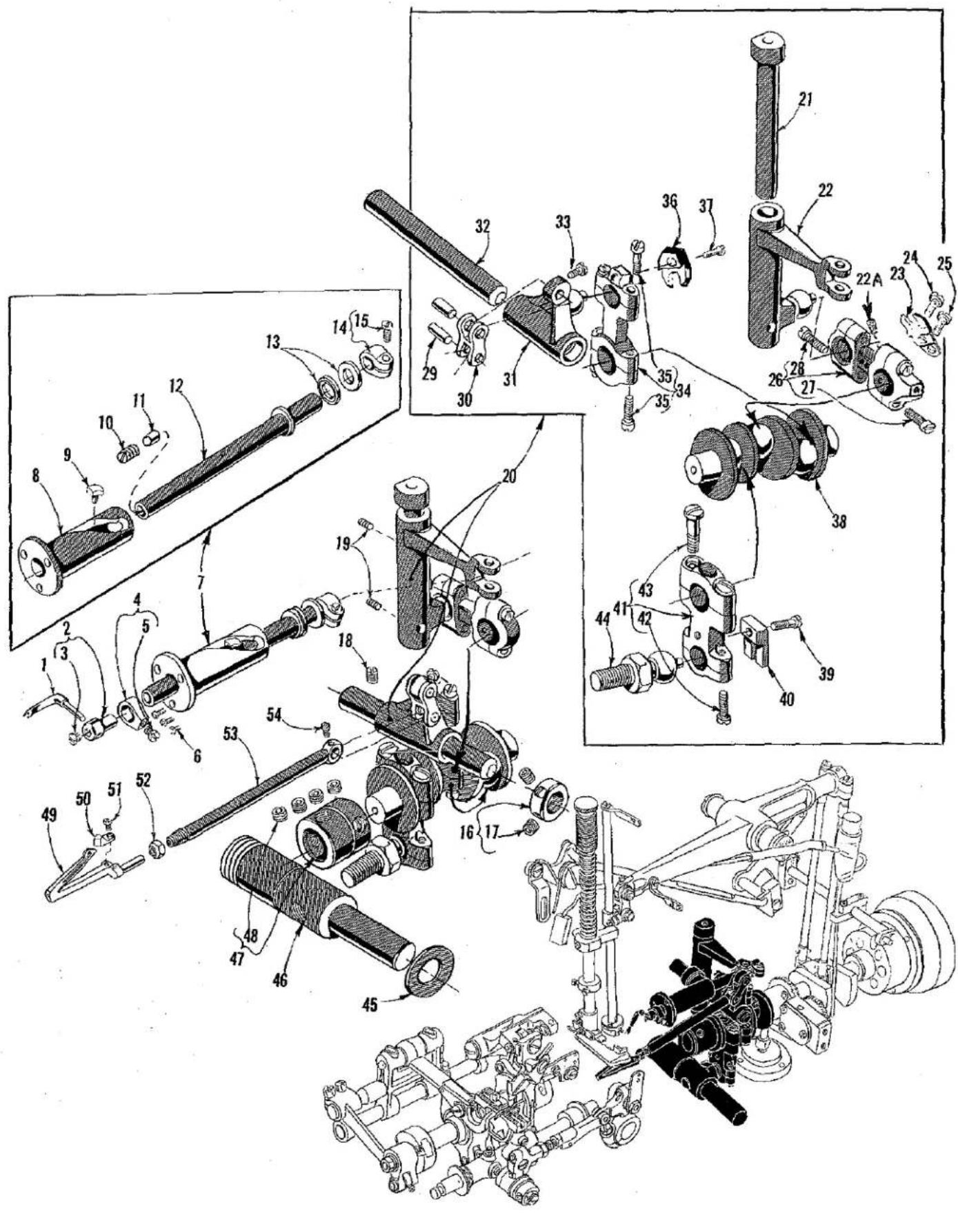
Technical diagram of mechanical assembly with numbered components and exploded viewsLOOPER (503) STITCH) AND SPREADER DRIVE MECHANISM
| Ref. No. | Part No. | Description | Amt. Req. |
| 1 | 52360 | Spreader, for 503 stitch | 1 |
| 2 | 39543 | Spreader Holder | 1 |
| 3 | 22564 G | Screw | 1 |
| 4 | 39543 A | Spreader Holder Collar | 1 |
| 5 | 22 KH | Screw | 1 |
| 6 | 22738 | Screw | 3 |
| 7 | 29476 KF | Spreader Motion Sub-Assembly | 1 |
| 8 | 52346 A | Spreader Bar Bushing and Cam Guide | 1 |
| 9 | 39543 T | Cam Follower | 1 |
| 10 | 22503 | Screw | 1 |
| 11 | 39543 E | Cam Follower Locking Clamp | 1 |
| 12 | 52346 | Spreader Bar | 1 |
| 13 | 39543 P | Thrust Washer | 2 |
| 14 | 39543 M | Clamp Collar | 1 |
| 15 | 22562 A | Screw | 1 |
| 16 | 482 C | Looper Shaft Collar | 1 |
| 17 | 22894 C | Screw | 2 |
| 18 | 95 | Screw | 1 |
| 19 | 22560 B | Screw | 2 |
| 20 | 29476 LG | Looper Drive Crank Assembly | 1 |
| 21 | 52346 C | Spreader Rocker Shaft | 1 |
| 22 | 52346 D | Spreader Drive Lever | 1 |
| 22 A | 666-255 | Felt Plug | 1 |
| 23 | 39544 J | Guide Fork, Spreader for 503 stitch | 1 |
| 24 | 22585 | Screw | 1 |
| 25 | 22585 A | Screw | 1 |
| 26 | 39544 N | Spreader Bar Drive Lever Connecting Rod | 1 |
| 27 | 22729 E | Screw | 2 |
| 28 | 22729 D | Screw | 2 |
| 29 | 39544 D | Link Pin | 2 |
| 30 | 39544 B | Link | 1 |
| 31 | 52344 E | Lower Looper Drive Lever, 503 stitch | 1 |
| 32 | 52344 D | Rock Shaft | 1 |
| 33 | J87 J | Screw | 1 |
| 34 | 52344 F | Looper Bar Driving Lever Connecting Rod | 1 |
| 35 | 22729 D | Screw | 4 |
| 36 | 41255 BA | Guide Fork, Looper | 1 |
| 37 | J87 J | Screw | 1 |
| 38 | 52343 D | Looper Drive Crank | 1 |
| 39 | 22729 | Screw | 1 |
| 40 | 51243 C | Ball Stud Fork | 1 |
| 41 | 52943 N | Looper Lever Crank Bearing | 1 |
| 42 | 22729 D | Screw | 2 |
| 43 | 22587 | Screw | 2 |
| 44 | 52943 P | Ball Stud | 1 |
| 45 | 52951 C | Spacer Washer | 1 |
| 46 | 52942 A | Looper Drive Lever Rocker Shaft | 1 |
| 47 | 56343 D | Looper Drive Crank Connection, left | 1 |
| 48 | 22894 X | Screw | 4 |
| 49 | 52308 B | Looper, for 503 stitch | 1 |
| 50 | 52310 | Looper Needle Guard | 1 |
| 51 | 22738 B | Screw | 1 |
| 52 | 39151 | Nut | 1 |
| 53 | 52344 | Lower Looper Bar | 1 |
| 54 | 77 | Screw | 1 |
text_image
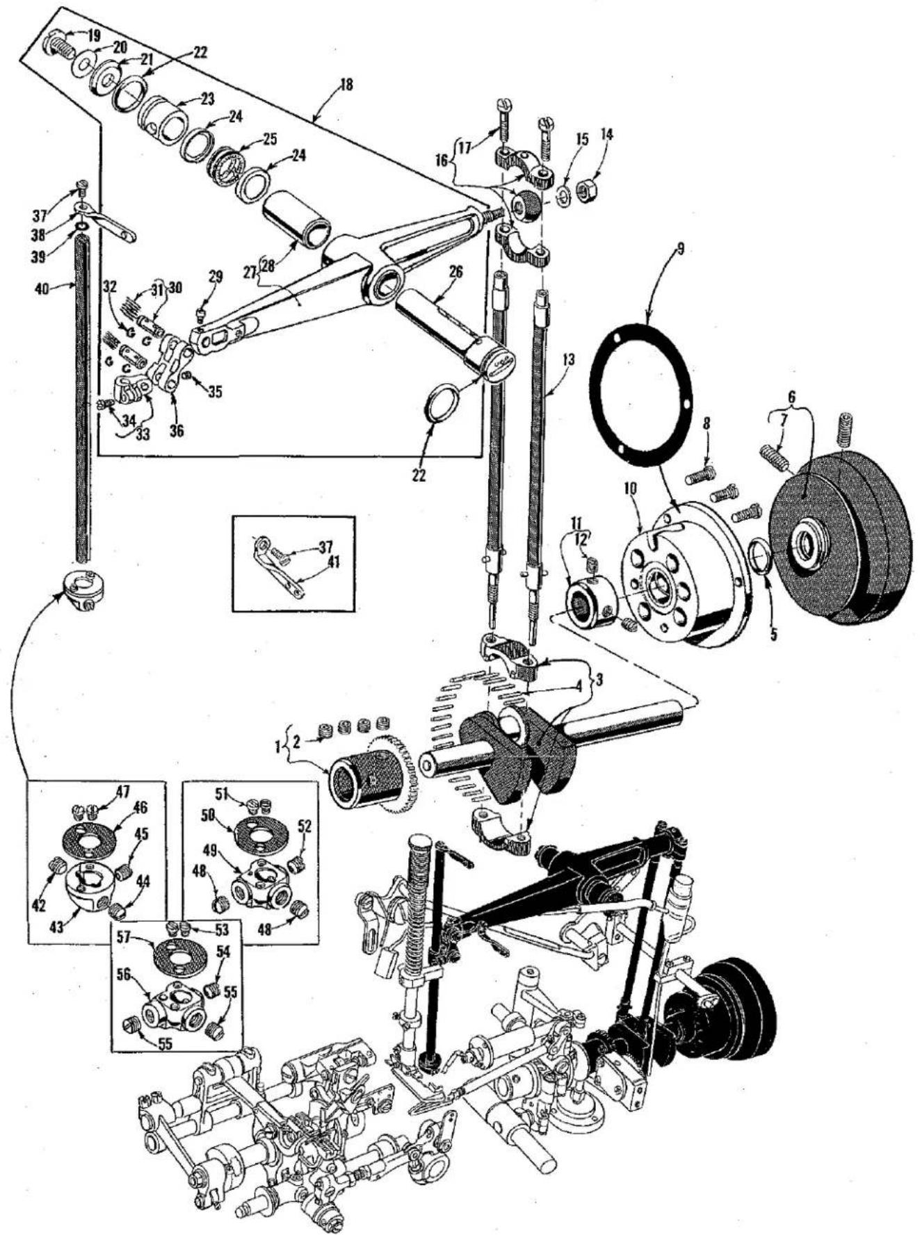
Technical diagram of a mechanical assembly with numbered parts and exploded views, likely for assembly or maintenance purposes.CRANKSHAFT, NEEDLE LEVER, NEEDLE BAR AND NEEDLE HEADS
| Ref. No. | Part No. | Description | Amt. Req. |
| 1 | 52343 C | Main Shaft Coupling and Oil Pump Driving Gear | 1 |
| 2 | 22894 X | Screw | 4 |
| 3 | 29476 KB | Crankshaft Assembly, .910 inch throw | 1 |
| 4 | 51216 M | Needle Bearing | 28 |
| 5 | 660-202 | Oil Seal Ring | 1 |
| 6 | 52921 B | Pulley | 1 |
| 7 | 22894 G | Screw | 2 |
| 8 | 22569 B | Screw | 3 |
| 9 | 56390 E | Gasket, for crankshaft bearing housing | 1 |
| 10 | 52891 B | Crankshaft Bushing Housing, including bushing | 1 |
| 11 | 51147 | Main Shaft Collar | 1 |
| 12 | 95 | Screw | 2 |
| 13 | 51216 G | Needle Lever Connecting Rod | 2 |
| 14 | 51216 P | Nut | 1 |
| 15 | 51216 N | Washer | 1 |
| 16 | 29066 R | Needle Lever Connecting Rod and Upper Bearing Assembly | 1 |
| 17 | 22559 G | Screw | 2 |
| 18 | 29348 AF | Needle Lever Assembly | 1 |
| 19 | 22586 R | Screw | 1 |
| 20 | 51250 F | Gasket | 1 |
| 21 | 51250 D | Washer | 1 |
| *22 | 660-212 | Oil Seal Ring | 2 |
| 23 | 56350 E | Needle Lever Collar | 1 |
| 24 | 56350 F | Thrust Washer | 2 |
| 25 | 660-614 | Temper Load Ring | 1 |
| 26 | 56350 D | Needle Lever Stud | 1 |
| 27 | 56315 A | Needle Lever | 1 |
| 28 | 56350 G | Bushing | 1 |
| 29 | 77 | Screw | 1 |
| 30 | 52336 A | Connection Pin | 2 |
| 31 | WO-3 | Wool Yarn (6 Strands) | |
| 32 | 660-215 | Retaining Ring | 4 |
| 33 | 51254 K | Needle Bar Connection | 1 |
| 34 | 22562 A | Screw | 1 |
| 35 | 22564 | Screw | 1 |
| 36 | 56354 D | Connecting Link | 1 |
| 37 | 22768 | Screw | 2 |
| 38 | 56358 | Needle Bar Thread Eyelet | 1 |
| 39 | 27-435 Blk. | Needle Bar Eyelet Washer | 1 |
| 40 | 52317 | Needle Bar | 1 |
| 41 | 56458 | Needle Lever Thread Eyelet | 1 |
| 42 | 88 | Screw | 1 |
| 43 | 52318 C-5-1/8 | Needle Holder, for Styles 52300 B-5-1/8, D-5-1/8,E-5-1/8 and F-5-1/8 | 1 |
| 44 | 22565 C | Screw | 1 |
| 45 | 89 | Screw | 1 |
| 46 | 52318 B | Needle Stop Plate | 1 |
| 47 | 22784 | Screw | 2 |
| 48 | 88 | Screw | 2 |
| 49 | 52318 A-12-3/16 | Needle Holder, for Styles 52300 B-12-1/8, D-12-1/8,B-12-3/16, D-12-3/16, E-12-3/16 and F-12-3/16 | 1 |
| 50 | 52318 B | Needle Stop Plate | 1 |
| 51 | 22784 | Screw | 2 |
| 52 | 89 | Screw | 1 |
| 53 | 22784 | Screw | 2 |
| 54 | 89 | Screw | 1 |
| 55 | 22565 C | Screw | 2 |
| 56 | 52318 C-8-1/8 | Needle Holder, for Styles 52300 B-8-1/8, D-8-1/8, E-8-1/8and F-8-1/8 | 1 |
| 57 | 52318 B | Needle Stop Plate | 1 |
* Note: Detail No. 22 is not part of assembly No. 29348 AF.

text_image
Technical diagram of a mechanical assembly with numbered components for identification and assembly reference.MAIN SHAFT AND FEED MECHANISM
| Ref. No. | Part No. | Description | Amt. Req. |
| 1 | 482 | Collar---- | 2 |
| 2 | 98 | Screw---- | 1 |
| 3 | 8 | Feed Rocker Shaft---- | 1 |
| 4 | 77 | Screw---- | 1 |
| 5 | 51235 A | Feed Rocker Arm---- | 1 |
| 6 | 51235 G | Washer---- | 2 |
| 7 | 22519 C | Screw---- | 2 |
| 8 | 51134 C | Feed Bar Shaft---- | 1 |
| 9 | 51235 | Feed Rocker---- | 1 |
| 10 | 98 | Screw---- | 2 |
| 11 | 51134 R | Lubricating Felt Guard---- | 1 |
| 12 | 51134 P | Lubricating Felt---- | 1 |
| 13 | 22834 | Screw---- | 1 |
| 14 | 51134 | Feed Bar---- | 1 |
| 15 | 22560 B | Screw---- | 1 |
| 16 | 538 | Screw---- | 1 |
| 17 | 51134 J | Feed Dog Holder Spacing Collar---- | 1 |
| 18 | 258 A | Nut---- | 1 |
| 19 | 22863 | Screw---- | 1 |
| 20 | 56334 E | Feed Dog Holder---- | 1 |
| 21 | 77 | Screw---- | 1 |
| 22 | Feed Dog (See Page 35)---- | 1 | |
| 23 | 22528 | Screw---- | 1 |
| 24 | 22585 B | Screw---- | 1 |
| 25 | 51225 W | Washer---- | 1 |
| 26 | 52325 | Needle Guard---- | 1 |
| 27 | 22801 | Screw---- | 1 |
| 28 | 269 | Nut---- | 1 |
| 29 | 20 | Washer---- | 1 |
| 30 | 51054 | Feed Crank Pin---- | 1 |
| 31 | 666-149 | Oil Wick---- | 1 |
| 32 | 51236 E | Feed Crank Link Assembly---- | 1 |
| 33 | 660-169 | Needle Bearing---- | 1 |
| 34 | 51236 D | Feed Crank Link---- | 1 |
| 35 | 51236 F | Ferrule---- | 1 |
| 36 | 22768 | Screw---- | 2 |
| 37 | 51236 B | Feed Crank Stud Cap---- | 1 |
| 38 | 82 | Screw---- | 1 |
| 39 | 51236 G | Feed Crank Stud---- | 1 |
| 40 | 52322 | Main Shaft---- | 1 |
| 41 | 29476 DR | Feed Lift Eccentric Assembly---- | 1 |
| 42 | 51145 A | Eccentric Bearing---- | 1 |
| 43 | 51142 C | Eccentric, .080 inch throw---- | 1 |
| 44 | 22894 D | Screw---- | 1 |
| 45 | 51236 A | Link Pin---- | 2 |
| 46 | 29476 DP | Knife Drive Eccentric Assembly---- | 1 |
| 47 | 51145 A | Eccentric Bearing---- | 1 |
| 48 | 51142 B | Eccentric, .140 inch throw---- | 1 |
| 49 | 22894 D | Screw---- | 1 |
| 50 | 52323 | Take-up---- | 1 |
| 51 | 96 | Screw, spot---- | 1 |
| 52 | 22580 D | Screw, set---- | 1 |
| 53 | 29476 DV | Looper Avoid Eccentric Assembly, for Styles 52300 B, D---- | 1 |
| 29476 DX | Looper Avoid Eccentric Assembly, for Styles 52300 E, F---- | 1 | |
| 54 | 51145 A | Eccentric Bearing---- | 1 |
| 55 | 51406 | Eccentric, .062 inch throw, for 29476 DV---- | 1 |
| 51306 | Eccentric, .072 inch throw, for 29476 DX---- | 1 | |
| 56 | 22894 D | Screw---- | 1 |
| 57 | 52336 | Link Pin, for knife drive---- | 1 |
| 58 | 660-215 | Retaining Ring---- | 2 |

text_image
Technical diagram of a mechanical assembly with numbered parts, likely for assembly or maintenance purposes.THREAD TENSION AND LIFTER LEVER PARTS
| Ref.No. | PartNo. | Description | Amt.Req. |
| 1 | 56356 | Presser Spring Regulator | 1 |
| 2 | 51256 C | Presser Spring | 1 |
| 3 | 53783 L | Presser Foot Lifter Lever Bell Crank | 1 |
| 4 | 53783 A | Lifter Lever Link | 1 |
| 5 | 22758 C | Screw | 1 |
| 6 | 402 | Screw | 1 |
| 7 | 51257 M | Presser Bar Connection and Guide | 1 |
| 8 | 531 | Screw | 1 |
| 9 | 51257 K | Presser Bar | 1 |
| 10 | 52888 B | Presser Bar Stop Collar | 1 |
| 11 | 22562 | Screw | 2 |
| 12 | 22557 B | Screw | 1 |
| 13 | 52883 S | Presser Foot Lifter Lever Bell Crank Spring | 1 |
| 14 | 53783 M | Presser Foot Lifter Lever Connecting Rod | 1 |
| 15 | 660-207 | Oil Seal Ring | 1 |
| 15A | 39552 C | Washer, for presser foot lifter lever | 1 |
| 16 | 51283 H | Presser Foot Lifter Lever | 1 |
| 17 | 21657 Y | Connection Assembly | 1 |
| 18 | 402 | Screw | 1 |
| 19 | 22596 | Screw | 1 |
| 20 | 21657 W | Tension Release Lever Shaft | 1 |
| 21 | 53783 N | Presser Foot Lifter Lever, internal | 1 |
| 22 | 22537 | Screw | 1 |
| 23 | 43266 | Nut | 3 |
| 24 | 51491 C | Lead-in Thread Eyelet | 5 |
| 25 | 56382 X | Tension Post Support | 1 |
| 26 | 51292 D | Tension Thread Eyelet | 5 |
| 27 | 668-25 | Eyelet | 2 |
| 28 | 668-28 | Eyelet Locking Ring | 2 |
| 29 | 21657-4 | Tension Release Separator | 1 |
| 30 | 51292 A | Tension Post Ferrule | 5 |
| 31 | 51292 G | Tension Post | 5 |
| 32 | 109 | Tension Disc | 10 |
| 33 | 51292 F-5 | Tension Spring (needle) | 2 |
| 34 | 51292 F-4 | Tension Spring (looper) | 3 |
| 35 | 51292 C | Tension Nut | 5 |
| 36 | Presser Foot (See Page 35) | 1 |
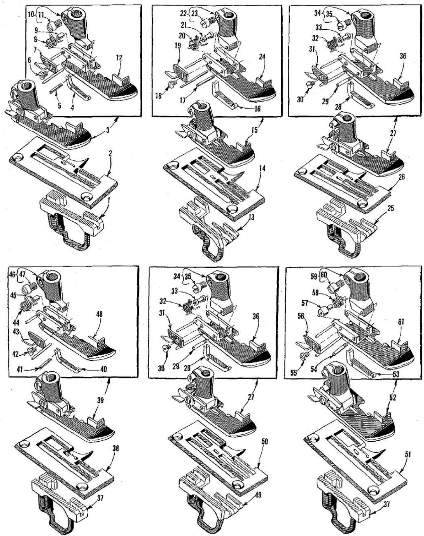
FEED DOGS, THROAT PLATES, PRESSER FEET
| Ref. No. | Part No. | Description | Amt. Req. |
| 1 | 52305 D-5-1/8 | Feed Dog, for Nos. 5-1/8, 8-1/8 gauges on Styles 52300 B, D---- | 1 |
| 2 | 52324 C-5-1/8 | Throat Plate, for No. 5-1/8 gauge on Styles 52300 B, D, E, F(10 to 16 stitches per inch)---- | 1 |
| 3 | 52327 B-5-1/8 | Presser Foot, for No. 5-1/8 gauge on Styles 52300 B, D---- | 1 |
| 4 | 52330 B | Needle Hole Section---- | 1 |
| 5 | 22799 F | Hinge Screw---- | 1 |
| 6 | 604 | Screw---- | 1 |
| 7 | 52930 AC | Chain Cutting Knife---- | 1 |
| 8 | 52330 D | Spring---- | 1 |
| 9 | 52930 W | Spring Bearing Sleeve---- | 1 |
| 10 | 52330 | Presser Foot Shank---- | 1 |
| 11 | 91 | Screw---- | 1 |
| 12 | 52330 G-5-1/8 | Presser Foot Bottom---- | 1 |
| 13 | 52305 D-12-1/8 | Feed Dog, for No. 12-1/8 gauge on Styles 52300 B, D---- | 1 |
| 14 | 52324 B-12-1/8 | Throat Plate, for No. 12-1/8 gauge on Styles 52300 B, D(10 to 16 stitches per inch)---- | 1 |
| 15 | 52330 B-12-1/8 | Presser Foot, for No. 12-1/8 gauge on Styles 52300 B, D---- | 1 |
| 16 | 52330 C | Needle Hole Section---- | 1 |
| 17 | 22799 R | Hinge Screw---- | 1 |
| 18 | 604 | Screw---- | 1 |
| 19 | 52930 AC | Chain Cutting Knife---- | 1 |
| 20 | 52330 D | Spring---- | 1 |
| 21 | 52330 E | Spring Bearing Sleeve---- | 1 |
| 22 | 52930 H | Presser Foot Shank---- | 1 |
| 23 | 91 | Screw---- | 1 |
| 24 | 52330 F-12-1/8 | Presser Foot Bottom---- | 1 |
| 25 | 52305 D-12-3/16 | Feed Dog, for No. 12-3/16 gauge on Styles 52300 B, D---- | 1 |
| 26 | 52324 B-12-3/16 | Throat Plate, for No. 12-3/16 gauge on Styles 52300 B, D, E, F(10 to 16 stitches per inch)---- | 1 |
| 27 | 52320 B-12-3/16 | Presser Foot, for No. 12-3/16 gauge on Styles 52300 B, D---- | 1 |
| 52320 D-12-3/16 | Presser Foot, for No. 12-3/16 gauge on Styles 52300 E, F---- | 1 | |
| 28 | 52330 C | Needle Hole Section---- | 1 |
| 29 | 22799 R | Hinge Screw---- | 1 |
| 30 | 604 | Screw---- | 1 |
| 31 | 52930 AC | Chain Cutting Knife---- | 1 |
| 32 | 52330 D | Spring---- | 1 |
| 33 | 52330 E | Spring Bearing Sleeve---- | 1 |
| 34 | 52930 H | Presser Foot Shank---- | 1 |
| 35 | 91 | Screw---- | 1 |
| 36 | 52330 F-12-3/16 | Presser Foot Bottom, for 52320 B-12-3/16---- | 1 |
| 52330 K-12-3/16 | Presser Foot Bottom, for 52320 D-12-3/16---- | 1 | |
| 37 | 52305 F-5-1/8 | Feed Dog, for No. 5-1/8, 8-1/8 gauges on Styles 52300 E, F---- | 1 |
| 38 | 52324 E-5-1/8 | Throat Plate, for No. 5-1/8 gauge on Styles 52300 E, F(7 to 10 stitches per inch)---- | 1 |
| 39 | 52320 D-5-1/8 | Presser Foot, for No. 5-1/8 gauge on Styles 52300 E, F---- | 1 |
| 40 | 52330 B | Needle Hole Section---- | 1 |
| 41 | 22799 F | Hinge Screw---- | 1 |
| 42 | 604 | Screw---- | 1 |
| 43 | 52930 AC | Chain Cutting Knife---- | 1 |
| 44 | 52330 D | Spring---- | 1 |
| 45 | 52930 W | Spring Bearing Sleeve---- | 1 |
| 46 | 52330 | Presser Foot Shank---- | 1 |
| 47 | 91 | Screw---- | 1 |
| 48 | 52330 K-5-1/8 | Presser Foot Bottom---- | 1 |
| 49 | 52305 F-12-3/16 | Feed Dog, for No. 12-3/16 gauge on Styles 52300 E, F---- | 1 |
| 50 | 52324 E-12-3/16 | Throat Plate, for No. 12-3/16 gauge on Styles 52300 E, F(7 to 10 stitches per inch)---- | 1 |
| 51 | 52324 C-8-1/8 | Throat Plate, for No. 8-1/8 gauge on Styles 52300 B, D, E, F(10 to 16 stitches per inch)---- | 1 |
| 52324 E-8-1/8 | Throat Plate, for No. 8-1/8 gauge on Style 52300 E, F(7 to 10 stitches per inch)---- | 1 | |
| 52 | 52320 B-8-1/8 | Presser Foot, for No. 8-1/8 gauge on Styles 52300 B, D---- | 1 |
| 52320 D-8-1/8 | Presser Foot, for No. 8-1/8 gauge on Styles 52300 E, F---- | 1 | |
| 53 | 52330 C | Needle Hole Section---- | 1 |
| 54 | 22799 R | Hinge Screw---- | 1 |
| 55 | 604 | Screw---- | 1 |
| 56 | 52930 AC | Chain Cutting Knife---- | 1 |
| 57 | 52930 AG | Spring Bearing Sleeve---- | 1 |
| 58 | 52330 D | Spring---- | 1 |
| 59 | 52930 H | Presser Foot Shank---- | 1 |
| 60 | 91 | Screw---- | 1 |
| 61 | 52330 F-8-1/8 | Presser Foot Bottom, for 52320 B-8-1/8---- | 1 |
| 52330 K-8-1/8 | Presser Foot Bottom, for 52320 D-8-1/8---- | 1 |
NOTE: No. 52330 J chip curler and No. 22561 screw for chip curler on presser feet No. 52320 D-5-1/8 and 52320 D-12-3/16 are not shown on picture plate.
text_image
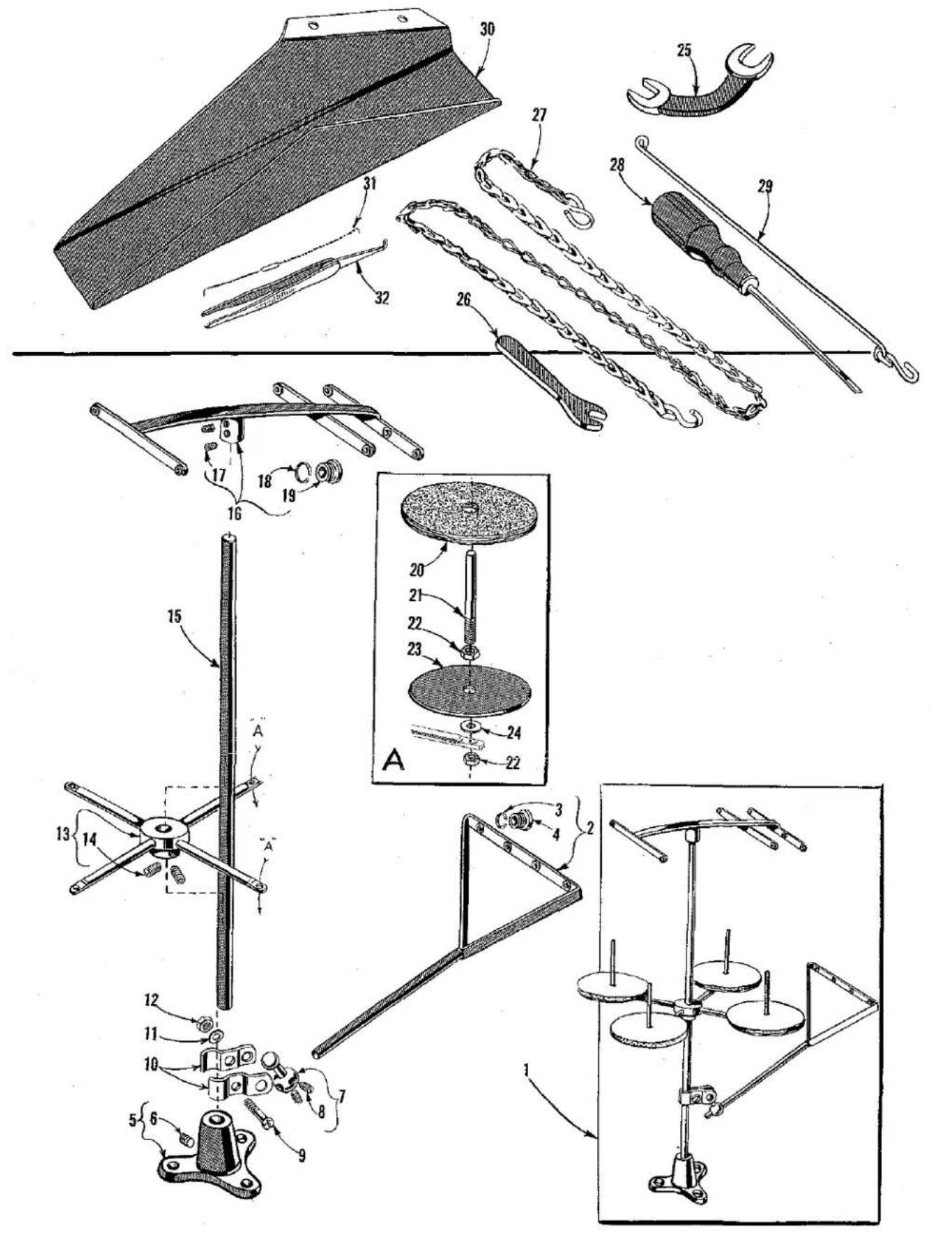
Technical diagram of mechanical tools and components with numbered parts, including clamps, weights, and a scale.THREAD STAND PARTS AND ACCESSORIES
| Ref.No. | PartNo. | Description | Amt.Req. |
| 1 | 21101 H-4 | Thread Stand Assembly---- | 1 |
| 2 | 21114 S-4 | Lead Eyelet---- | 1 |
| 3 | 21114 M | Eyelet Locking Ring---- | 4 |
| 4 | 21114 L | Eyelet---- | 4 |
| 5 | 21114 A | Thread Stand Base---- | 1 |
| 6 | 22651 CD-3 | Screw---- | 1 |
| 7 | 21114 T | Lead Eyelet Socket Ball---- | 1 |
| 8 | 22651 CD-4 | Screw---- | 2 |
| 9 | 22810 | Screw---- | 1 |
| 10 | 21114 U | Lead Eyelet Ball Split Socket---- | 2 |
| 11 | 652-16 | Washer---- | 1 |
| 12 | 21104 H | Nut---- | 1 |
| 13 | 21114 D-4 | Spool Seat Support---- | 1 |
| 14 | 22651 CD-5 | Screw---- | 2 |
| 15 | 21104 B-24 | Thread Stand Rod---- | 1 |
| 16 | 21114 H-4 | Eyelet Support---- | 1 |
| 17 | 22651 CD-4 | Screw---- | 2 |
| 18 | 21114 M | Eyelet Locking Ring---- | 8 |
| 19 | 21114 L | Eyelet---- | 8 |
| 20 | 21104 V | Pad---- | 4 |
| 21 | 21114 W | Spool Pin---- | 4 |
| 22 | 258 A | Nut---- | 8 |
| 23 | 21114 | Spool Seat Disc---- | 4 |
| 24 | 652-16 | Washer---- | 4 |
| 25 | 21388 W | Wrench, double end, curved, 9/32 inch opening---- | 1 |
| 26 | 21388 | Wrench, single end, 3/8 inch opening---- | 1 |
| 27 | 421 D-28 | Treadle Chain, 28 inches long---- | 1 |
| 28 | 21201 | Screw Driver, 9/64 inch round blade, length over-all7 3/8 inches---- | 1 |
| 29 | 51493 BC | Lifter Link---- | 1 |
| 30 | 51278 F | Chip Chute---- | 1 |
| 31 | 52399 | Threading Wire---- | 1 |
| 32 | 660-240 | Thread Tweezers---- | 1 |
NUMERICAL INDEX OF PARTS
| Part No. | Page No. | Part No. | Page No. | Part No. | Page No. |
| WO-3. | 29 | 668-28 | 33 | 22738 | 27 |
| 8. | 31 | 719 | 17 | 22738 B | 27 |
| 18. | 25 | 906 | 23 | 22758 C | 33 |
| 20. | 17, 25, 31 | 7947 | 17 | 22768 | 25, 29, 31 |
| 22 KH | 27 | 15037 A | 25 | 22784 | 29 |
| 25 B. | 19 | 15465 F | 25 | 22798 | 23 |
| 25 S. | 19 | 21101 H | 37 | 22799 F | 35 |
| 27-435 Blk | 29 | 21104 B | 37 | 22799 M | 17 |
| 28. | 17, 19 | 21104 H | 37 | 22799 R | 35 |
| 50-216 Blk | 17 | 21104 V | 37 | 22801 | 31 |
| 50-458 Blk | 25 | 21114 | 37 | 22810 | 37 |
| 50-648 Blk | 21 | 21114 A | 37 | 22823 A | 21 |
| 50-789 Blk | 17 | 21114 D | 37 | 22823 B | 21 |
| 52 A. | 17 | 21114 H | 37 | 22829 | 25 |
| 73. | 25 | 21114 L | 37 | 22834 | 31 |
| 77. | 23, 27, 29 | 21114 M | 37 | 22839 | 19 |
| 31 | 21114 S | 37 | 22848 | 17 | |
| 80. | 19 | 21114 T | 37 | 22863 | 31 |
| 82. | 31 | 21114 U | 37 | 22882 A | 25 |
| 87. | 19 | 21114 W | 37 | 22889 A | 17 |
| 87 U. | 17 | 21201 | 37 | 22889 C | 21 |
| J87 J. | 27 | 21212 | 21 | 22889 D | 21 |
| 88. | 25, 29 | BB21375 AH | 17 | 22894 C | 23, 27 |
| 89. | 29 | 21388 | 37 | 22894 D | 31 |
| 90. | 17, 21 | 21388 W | 37 | 22894 G | 29 |
| 91. | 35 | 21657-4 | 33 | 22894 J | 23 |
| 93. | 17 | 21657 E | 17 | 22894 P | 23 |
| 95. | 17, 27, 29 | 21657 W | 33 | 22894 X | 27, 29 |
| 96. | 25, 31 | 21657 X | 21 | 29066 R | 29 |
| 97. | 23 | 21657 Y | 33 | 29192 | 25 |
| 98. | 25, 31 | 22503 | 27 | 29348 AF | 29 |
| 98 A. | 17 | 22513 | 17 | 29476 DP | 31 |
| 109. | 33 | 22517 B | 17 | 29476 DR | 31 |
| 258. | 21 | 22519 C | 31 | 29476 DV | 31 |
| 258 A. | 21, 25, 31 | 22519 H | 25 | 29476 DX | 31 |
| 37 | 22528 | 17, 31 | 29476 KB | 29 | |
| 269. | 25, 31 | 22537 | 33 | 29476 KF | 27 |
| 376 A. | 19 | 22539 H | 21 | 29476 LG | 27 |
| 402. | 33 | 22541 B | 17 | 35178 D | 21 |
| 421 D. | 37 | 22542 | 17 | 35731 A | 17 |
| 482. | 31 | 22548 | 19 | 35766 | 19 |
| 482 C. | 27 | 22557 B | 33 | 39151 | 27 |
| 531. | 33 | 22559 G | 29 | 39158 G | 19 |
| 538. | 31 | 22560 B | 21, 27, 31 | 39158 U | 19 |
| 539. | 17 | 22561 | 35 | 39171 N | 23 |
| 604. | 19, 35 | 22562 | 33 | 39173 | 23 |
| 643-127 Blk | 21 | 22562 A | 27, 29 | 39270 K | 23 |
| 652-16. | 37 | 22564 | 29 | 39543 | 27 |
| 660-136. | 21 | 22564 G | 27 | 39543 A | 27 |
| 660-169. | 31 | 22565 C | 29 | 39543 E | 27 |
| 660-202. | 29 | 22568 | 19 | 39543 M | 27 |
| 660-206. | 23 | 22569 B | 17, 21, 29 | 39543 P | 27 |
| 660-207. | 33 | 22571 A | 21 | 39543 T | 27 |
| 660-212. | 29 | 22580 D | 31 | 39544 B | 27 |
| 660-215. | 29, 31 | 22585 | 21, 27 | 39544 D | 27 |
| 660-240. | 37 | 22585 A | 27 | 39544 J | 27 |
| 660-310. | 25 | 22585 B | 31 | 39544 N | 27 |
| 660-614. | 29 | 22585 C | 23 | 39552 C | 33 |
| 666-65. | 21 | 22586 R | 29 | 39582 L | 17 |
| 666-111. | 21 | 22587 | 27 | 39595 | 21 |
| 666-114. | 21 | 22588 A | 19 | 41255 BA | 27 |
| 666-118. | 21 | 22595 | 23 | 41355 U | 25 |
| 666-149. | 31 | 22596 | 21, 33 | 43266 | 33 |
| 666-179. | 21 | 22651 CD | 37 | 51054 | 31 |
| 666-201. | 21 | 22711 | 17, 23 | 51134 | 31 |
| 666-208. | 21 | 22729 | 27 | 51134 C | 31 |
| 666-209. | 21 | 22729 A | 21 | 51134 J | 31 |
| 666-214. | 21 | 22729 B | 21 | 51134 P | 31 |
| 666-255. | 27 | 22729 C | 25 | 51134 R | 31 |
| 667 C. | 23 | 22729 D | 27 | 51142 B | 31 |
| 668-25. | 33 | 22729 E | 27 | 51142 C | 31 |
| 22729 L | 23 |
NOTE: Only the basic part numbers are shown in the index. For various gauges, capacities, etc., available, refer to the listings on pages indicated.
NUMERICAL INDEX OF PARTS
| Part No. | Page No. | Part No. | Page No. | Part No. | Page No. |
| 51144 | 25 | 52301 | 19 | 52390 | 21 |
| 51145 A | 31 | 52305 D | 35 | 52393 | 21 |
| 51147 | 29 | 52305 F | 35 | 52393 A | 21 |
| 51213 | 25 | 52308 | 25 | 52393 D | 21 |
| 51216 G | 29 | 52308 B | 27 | 52393 H | 21 |
| 51216 M | 29 | 52310 | 27 | 52393 J | 21 |
| 51216 N | 25, 29 | 52317 | 29 | 52393 K | 21 |
| 51216 P | 29 | 52318 A | 29 | 52393 L | 21 |
| 51225 W | 31 | 52318 B | 29 | 52394 C | 23 |
| 51235 | 31 | 52318 C | 29 | 52399 | 37 |
| 51235 A | 31 | 52320 B | 35 | 52804 A | 17 |
| 51235 G | 31 | 52320 D | 35 | 52882 P | 17 |
| 51236 A | 31 | 52322 | 31 | 52882 U | 19 |
| 51236 B | 31 | 52323 | 31 | 52882 W | 17 |
| 51236 D | 31 | 52324 B | 35 | 52882 AA | 17 |
| 51236 E | 31 | 52324 C | 35 | 52882 AC | 17 |
| 51236 F | 31 | 52324 E | 35 | 52882 AD | 17 |
| 51236 G | 31 | 52325 | 31 | 52882 AE | 19 |
| 51240 D | 25 | 52327 B | 35 | 52883 R | 21 |
| 51242 M | 25 | 52330 | 35 | 52883 S | 33 |
| 51243 C | 27 | 52330 B | 35 | 52885 L | 17 |
| 51244 | 25 | 52330 C | 35 | 52888 B | 33 |
| 51244 B | 25 | 52330 D | 35 | 52890 C | 21 |
| 51244 L | 25 | 52330 E | 35 | 52891 B | 21, 29 |
| 51244 N | 25 | 52330 F | 35 | 52894 AB | 21 |
| 51246 | 25 | 52330 G | 35 | 52894 AK | 21 |
| 51250 D | 29 | 52330 J | 35 | 52921 B | 29 |
| 51250 F | 29 | 52330 K | 35 | 52930 H | 35 |
| 51254 C | 21 | 52336 | 31 | 52930 W | 35 |
| 51254 D | 21 | 52336 A | 29 | 52930 AC | 35 |
| 51254 K | 29 | 52343 C | 29 | 52930 AG | 35 |
| 51256 C | 33 | 52343 D | 27 | 52936 | 21 |
| 51257 K | 33 | 52344 | 27 | 52942 A | 27 |
| 51257 M | 33 | 52344 D | 27 | 52942 P | 25 |
| 51257 AA | 21 | 52344 E | 27 | 52942 R | 25 |
| 51270 B | 17 | 52344 F | 27 | 52942 W | 21 |
| 51272 C | 23 | 52344 H | 25 | 52942 X | 21 |
| 51272 D | 23 | 52345 | 23 | 52942 Y | 17 |
| 51278 F | 37 | 52345 A | 23 | 52943 N | 27 |
| 51278 G | 19 | 52345 B | 23 | 52943 P | 27 |
| 51280 E | 21 | 52346 | 27 | 52944 T | 21 |
| 51280 J | 19 | 52346 A | 27 | 52944 U | 21 |
| 51282 Y | 17 | 52346 C | 27 | 52951 C | 27 |
| 51282 Z | 17 | 52346 D | 27 | 52958 G | 17 |
| 51282 AC | 17 | 52349 | 19 | 52970 E | 23 |
| 51283 H | 33 | 52350 A | 19 | 52994 AC | 21 |
| 51290 T | 21 | 52350 B | 19 | 53783 A | 33 |
| 51292 A | 33 | 52357 A | 17 | 53783 L | 33 |
| 51292 C | 33 | 52358 A | 17 | 53783 M | 33 |
| 51292 D | 33 | 52358 C | 17 | 53783 N | 33 |
| 51292 F | 33 | 52358 D | 17 | 55241 N | 25 |
| 51292 G | 33 | 52358 E | 17 | 55244 G | 25 |
| 51294 K | 21 | 52360 | 27 | 56315 A | 29 |
| 51294 M | 21 | 52370 A | 23 | 56334 E | 31 |
| 51294 P | 17 | 52371 A | 23 | 56341 E | 25 |
| 51294 R | 17 | 52371 B | 23 | 56341 G | 25 |
| 51294 U | 21 | 52372 | 23 | 56341 M | 25 |
| 51294 Z | 21 | 52372 A | 23 | 56343 D | 27 |
| 51295 B | 21 | 52373 A | 23 | 56350 D | 29 |
| 51306 | 31 | 52373 B | 23 | 56350 E | 29 |
| 51406 | 31 | 52373 C | 23 | 56350 F | 29 |
| 51472 A | 23 | 52373 D | 23 | 56350 G | 29 |
| 51472 B | 23 | 52373 E | 23 | 56354 D | 29 |
| 51491 C | 33 | 52378 C | 19 | 56356 | 33 |
| 51493 E | 21 | 52378 D | 19 | 56358 | 29 |
| 51493 AZ | 21 | 52378 E | 19 | 56382 X | 33 |
| 51493 BC | 37 | 52380 B | 19 | 56382 AC | 17 |
| 51493 BG | 21 | 52381 B | 19 | 56390 E | 29 |
| 51493 BH | 21 | 52381 C | 19 | 56458 | 29 |
| 51493 BJ | 21 | 52382 | 19 | 57885 | 17 |
| 51493 BK | 21 | 52382 A | 19 | 57885 B | 17 |
| 51745 | 25 | 52385 | 17 | 61341 J | 21 |
NOTE: Only the basic part numbers are shown in the index. For various gauges, capacities, etc. available, refer to the listing on pages indicated.

natural_image
Black-and-white world map showing continents and latitude/longitude lines (no text or labels)WORLDWIDE SALES AND SERVICE
Union Special Corporation maintains sales and service facilities throughout the world. These offices will aid you in the selection of the right sewing equipment for your particular operation. Union Special Corporation representatives and service technicians are factory trained and are able to serve your needs promptly and efficiently. Whatever your location, there is a qualified representative to serve you.
It is important to remember that LEWIS® machines are also products of Union Special Corporation, thus offering the Finest Quality sewing machines.
Corporate Offices:
One Union Special Plaza
Huntley, IL 60142
(708) 669-5101
Union Special GmbH
Raiffeisenstrasse 3
D-71696 Möglingen, Germany
Tel. 07141-2470
Brussels, Belgium
Commerce, CA
Leicester, England
Lille, France
Miami, FL
Möglingen, Germany
Huntley, IL
Milan, Italy
Osaka, Japan
Hong Kong
Charlotte, N.C.
Warminster, PA
Montreal, Quebec
El Paso, TX
Mission, TX
Other Representatives throughout all parts of the world.

Finest Quality
Union Special INDUSTRIAL SEWING EQUIPMENT