Stereo Line In 1U - Master Keyboard Intellijel - Free user manual and instructions
Find the device manual for free Stereo Line In 1U Intellijel in PDF.

User questions about Stereo Line In 1U Intellijel
0 question about this device. Answer the ones you know or ask your own.
Ask a new question about this device
Download the instructions for your Master Keyboard in PDF format for free! Find your manual Stereo Line In 1U - Intellijel and take your electronic device back in hand. On this page are published all the documents necessary for the use of your device. Stereo Line In 1U by Intellijel.
USER MANUAL Stereo Line In 1U Intellijel
Stereo Line In 1U System
Stereo Balanced Line Audio Input
text_image
IN L R OUT L OUT R Stereo Line In 1U+
text_image
LINE IN THIS BALANCED L RStereo In Jacks 1U
OR

text_image
intellijel intellijel7U Case with 2nd Gen Audio Jacks
OR

Connecting a Stereo Line In 1U to a Stereo In Jacks 1U 7
Connecting a Stereo Line In 1U to the 14 " Jacks on a 7U Case 8
Connecting Two Stereo Line In 1U Modules to a 7U Case 9
Connecting Both a Stereo Line In 1U and a Stereo Line Out 1U to a 7U Case 9
Connecting a Stereo Line In 1U to a Palette Case's 14 " Jacks 10
Front Panel (Stereo Line In 1U) 11
Controls 11
Inputs & Outputs 12
Front Panel (Stereo In Jacks 1U) 13
Inputs & Outputs 13
Technical Specifications 14
Stereo Line In 1U 14
Stereo In Jacks 1U 14
Compliance

This device complies with Part 15 of the FCC Rules. Operation is subfollowing two conditions: (1) this device may not cause harmful interference (2) this device must accept any interference received, including interference may cause undesired operation.
Changes or modifications not expressly approved by Intellij Designs, Ir void the user's authority to operate the equipment.
Any digital equipment has been tested and found to comply with the Class A digital device, pursuant to part 15 of the FCC Rules. These designed to provide reasonable protection against harmful interference with equipment is operated in a commercial environment. This equipment generates uses, and can radiate radio frequency energy and, if not installed and accordance with the instruction manual, may cause harmful interference communications.

This device meets the requirements of the following standards and dire EMC: 2014/30/EU
EN55032:2015 ; EN55103-2:2009 (EN55024) ; EN61000-3-2 ; EN61000-3-
Low Voltage: 2014/35/EU
EN 60065:2002+A1:2006+A11:2008+A2:2010+A12:2011
RoHS2: 2011/65/EU
WEEE: 2012/19/EU
System Overview
Use the Stereo Line In 1U system to bring external audio into your modular system for processing. The system works with balanced +4 dBu professional audio products and with -10dbV unbalanced gear.
The Stereo Line In 1U system comprises two components:
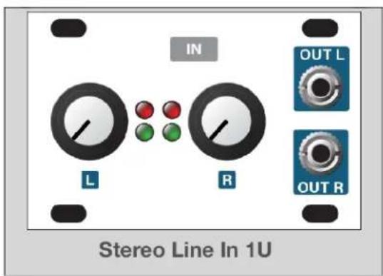
- The Stereo Line In 1U module:
text_image
IN L R OUT L OUT RA ribbon cable connects this module to either the Ster Jacks 1U module, or to a compatible Intellijel case with 14 jacks. It has independent gain controls for the left channels, along with signal level LEDs. It contains all the control circuitry to drive a eurorack system at the proper and features two 18 output jacks for patching your external signal into other eurorack modules.
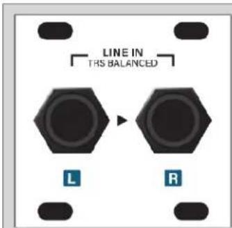
- Either a Stereo In Jacks 1U module, or a case with built-in 14 " audio jacks, such as Intellijel's Palette or 7U cases (with a 2nd generation Audio Jacks board):
text_image
LINE IN TRS BALANCED L RStereo In Jacks 1U Module
If you don't own an Intellijel case with built-in compatib jacks, then you need to purchase a Stereo In Jacks 1U module, which connects via ribbon cable to the Stereo Line In 1U module to provide the 14 " TRS input jacks necessary fo connecting external audio sources.
text_image
intellijelPalette Case
If you own an Intellij Palette case, you can connect Line In 1U module directly to its built-in pair of 14 " jao than purchasing a Stereo In Jacks 1U.

natural_image
Exterior view of a white interlocking electronic device with green circuit board (no visible text or symbols)7U Case w/ 2nd Generation Audio Jacks Board
If you own an Intellijel 7U case with a 2nd generation Jacks Board (distinguished by the row of shrouded heat along its bottom edge), you can use its jacks rather than purchasing a Stereo In Jacks 1U module.
If your 7U case has a 1st generation Audio Jacks Board, you can purchase a 2nd generation board to replace your old board.
Installation
This module is designed for use within an Intellijel-standard 1U row, such as contained within the Intellijel 4U and 7U Eurorack cases. Intellijel's 1U specification is derived from the Eurorack mechanical specification set by Doepfer that is designed to support the use of lipped rails within industry standard rack heights.

text_image
7.5mm Ø 3.2mm x4 3.0mm 33.65mm mm
text_image
1U 44.45mm (1.75in) 39.65mm 22.5mm TYPICAL PCB 1U PANELBefore Your Start
Intellijel Eurorack modules are designed to be used with a Eurorack-compatible case and power supply. We recommend you use Intellijel cases and power supplies.
Before installing a new module in your case, you must ensure your power supply has a free power header and sufficient available capacity to power the module:
- Sum up the specified +12V current draw for all modules, including the new one. Do the same for the -12 V and +5V current draw. The current draw will be specified in the manufacturer's technical specifications for each module.
- Compare each of the sums to specifications for your case's power supply.
- Only proceed with installation if none of the values exceeds the power supply's specifications. Otherwise you must remove modules to free up capacity or upgrade your power supply.
You will also need to ensure your case has enough free space (hp) to fit the new module. To prevent screws or other debris from falling into the case and shorting any electrical contacts, do not leave gaps between adjacent modules, and cover all unused areas with blank panels.
Similarly, do not use open frames or any other enclosure that exposes the backside of any module or the power distribution board.
You can use a tool like ModularGrid to assist in your planning. Failure to adequately power your modules may result in damage to your modules or power supply. If you are unsure, please contact us before proceeding.
Installing Your Module
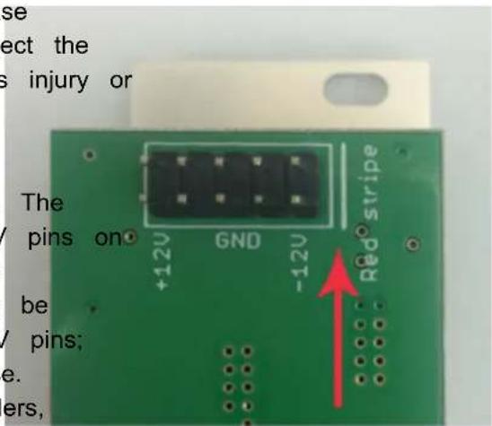
When installing or removing a module from your case always turn off the power to the case and disconnect the power cable. Failure to do so may result in serious injury or equipment damage.
Ensure the 10-pin connector on the power cable is connected correctly to the module before proceeding. The red stripe on the cable must line up with the -12V pins the module's power connector. Different modules use different ways to indicate the -12V pins. Some may be labelled with "-12V;" a white stripe next to the -12V pins; the words "red stripe;" or some combination of these. Additionally, some modules may have shrouded headers, thus preventing backward connections.
text_image
se ect the s injury or The pins on +12V GND -12V Red stripe be / pins; e. ers,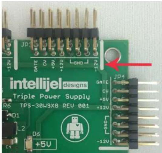
text_image
intellijel designs Triple Power Supply TPS-30W9X8 REV 001 GATE CU +5V +12V JP4 -12V -12V C1 D6 +5V -12VMost modules will come with the cable already connected but it is good to double check the orientation. Be aware that some modules may have headers that serve other purposes so ensure the power cable is connected to the right one.
The other end of the cable, with a 16-pin connector, connects to the power bus board of your Eurorack case. Ensure the red stripe on the cable lines up with the -12V pins on the bus board. On Intellijel power supplies the pins are labelled with the label "-12V" and a thick white stripe:
If you are using another manufacturer's power supply, check their documentation for instructions.
Once connected, the cabling between the module and power supply should resemble the picture below:

natural_image
Close-up of a green circuit board with a white flexible cable wrapped around it, no visible text or symbols on the main subject.Before reconnecting power and turning on your modular system, double check that the ribbon cable is fully seated on both ends and that all the pins are correctly aligned. If the pins are misaligned in any direction or the ribbon is backwards you can cause damage to your module, power supply, or other modules.
After you have confirmed all the connections, you can reconnect the power cable and turn on
your modular system. You should immediately check that all your modules have powered on and are functioning correctly. If you notice any anomalies, turn your system off right away and check your cabling again for mistakes.
Connecting a Stereo Line In 1U to a Stereo In Jacks 1U
The Stereo Line In 1U module ships with a ribbon cable for connecting to a pair of 14 " TRS audio jacks — either those built-in to the 2nd generation Audio Jacks Board installed in Intellijel 7U cases; an Intellijel Palette case, or those contained within the separately available Stereo In Jacks 1U module.
To connect the Stereo Line In 1U module to the Stereo In Jacks 1U module:
- Connect one end of the supplied ribbon cable to the keyed 6-pin connector on the Stereo Line In 1U module and the other end to the keyed 6-pin connector on the Stereo In Jacks 1U.

text_image
STEREO IN JACKS 1U STEREO LINE IN 1UThe signal arriving at the Stereo In Jacks' 1/4" TRS jacks is transferred into the Stereo Line In 1U module for patching into your eurorack system at the correct voltage levels.
Connecting a Stereo Line In 1U to the 14 " Jacks on a 7U Case
The Stereo Line In 1U module ships with a ribbon cable for connecting to a pair of 14 TRS audio jacks — either those built-in to the 2nd generation Audio Jacks Board installed in Intellijel 7U cases; an Intellijel Palette case, or those contained within the separately available Stereo In Jacks 1U module
To connect the Stereo Line In 1U module to the jacks installed in your 7U case:
- Determine whether your case uses a 1st or 2nd generation Audio Jacks Board.
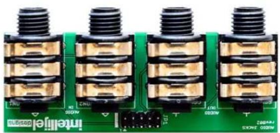
1st generation boards (included with cases built before early 2019) have a single connector along the bottom. 2nd generation boards have a large shrouded header flanked by two smaller shrouded headers, flanked by two link connectors.
natural_image
Close-up of four identical black threaded electronic components mounted on a green circuit board (no visible text or symbols)1st GENERATION AUDIO JACKS
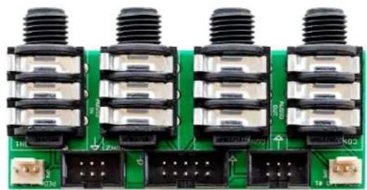
natural_image
Close-up of a green circuit board with four black threaded components and terminal connectors (no visible text or symbols)2nd GENERATION AUDIO JACKS
IMPORTANT: You can only connect the Stereo Line In 1U module to 7U cases with 2nd generation Audio Jacks Boards. If you have a 1st generation board, you can purchase 2nd generation board to replace your original Audio Jacks Board.
- Connect one end of the supplied ribbon cable to the keyed 6-pin connector on the Stereo Line In 1U module and the other end to on of the two keyed 6-pin connectors on the Audio Jacks Board.
Audio arriving at the corresponding pair o jacks is sent through to the Stereo Line module for patching into your eurorack system at the correct voltage levels.
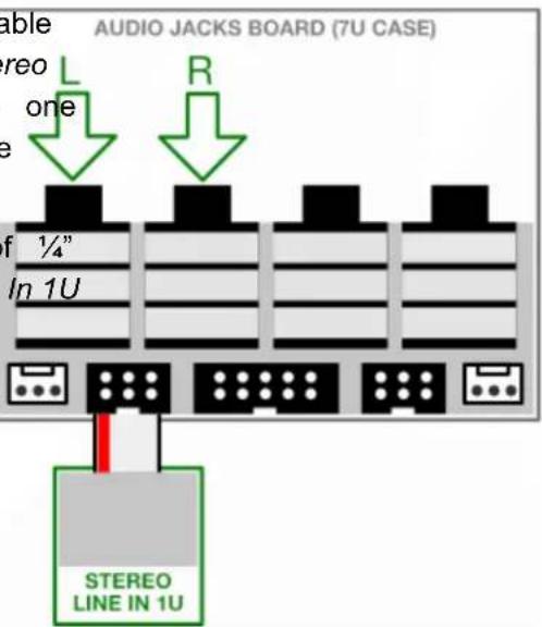
text_image
AUDIO JACKS BOARD (7U CASE) able Stereo one L R of ¼" In 1U STEREO LINE IN 1UConnecting Two Stereo Line In 1U Modules to a 7U Case
You can connect a second Stereo Line In 1U to the other 6-pin connector on the Audio Ja board, giving you four audio inputs in a 7U
-
Using the ribbon cable supplied with the Stereo Line In 1U module, connect it the two keyed 6-pin connectors on the generation Audio Jacks Board.
-
Connect the other Stereo Line In 1U module to the remaining keyed 6-pin connector Audio Jacks Board.
The input for each Stereo Line In 1U module appears at the corresponding set of 14 " jacks on the Audio Jacks Board.

text_image
module AUDIO JACKS BOARD (7U CASE) L R L R cks case. to or of 2nd on the module jacks STEREO LINE IN 1U STEREO LINE IN 1UConnecting Both a Stereo Line In 1U and a Stereo Line Out 1U to a 7U Case
You can connect both a Stereo Line In 1U and a Stereo Line Out 1U module to the Audio Jacks board, giving you two inputs and two outputs on a 7U case.
-
As discussed previously, connect the Stereo Line In 1U module to one of the two key 6-pin connectors on the 2nd generation A Jacks Board.
-
Using the ribbon cable supplied with the Stereo Line Out 1U module, connect it other keyed 6-pin connector on the 2nd generation Audio Jacks Board.
Two of the 7U case's 14 " inputs will then feed the Stereo Line In 1U module, and the other two will serve as outputs for the Stereo Line Out 1U module.
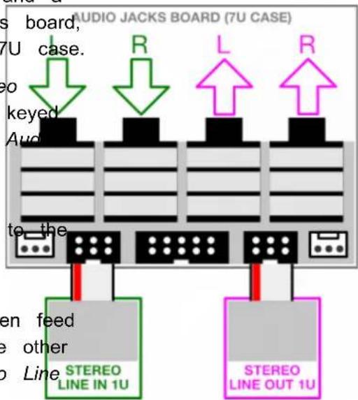
text_image
AUDIO JACKS BOARD (7U CASE) s board, 7U case. eo keyed Audi to the R L R STEREO LINE IN 1U STEREO LINE OUT 1UConnecting a Stereo Line In 1U to a Palette Case's 14 " Jacks
The Stereo Line In 1U module ships with a ribbon cable for connecting to a pair of 14 TRS audio jacks — either those built-in to the 2nd generation Audio Jacks Board installed in Intellijel 7U cases; an Intellijel Palette case, or those contained within the separately available Stereo Out Jacks 1U module.
To connect the Stereo Line In 1U module to the jacks installed in your Intellij Palette case:
- Connect one end of the supplied ribbon cable to the keyed 6-pin connector on the Stereo Line In 1U module and the other end to the single keyed 6-pin connector on the Palette case's built-in circuit board.
Audio arriving at the corresponding pair of 14 " jacks is sent through to the Stereo Line In 1U module for patching into your eurorack system at the correct voltage levels.
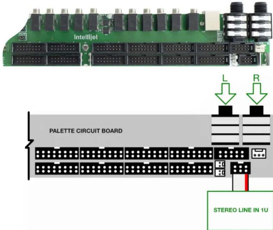
text_image
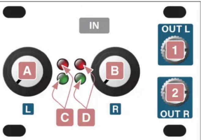
intellijel PALETTE CIRCUIT BOARD L R STEREO LINE IN 1UFront Panel (Stereo Line In 1U)
Controls
A. INPUT GAIN L
Scales the input signal level, which arrives via a 14 " jack (ie. a Stereo Line In 1U module, a Palette case, or a 7U case with 2nd generation Audio Jacks board) connected to the rear of this module.
Fully counterclockwise, the input is completely attenuated. Set fully clockwise, +15dB of gain is applied to the input signal before sending it to the OUT L [1] jack.
flowchart
graph TD
    A["A"] --> C["C"]
    B["B"] --> D["D"]
    C --> D
    D --> E["OUT L 1"]
    D --> F["OUT R 2"]
    style A fill:#f9f,stroke:#333
    style B fill:#f9f,stroke:#333
    style C fill:#ccf,stroke:#333
    style D fill:#ccf,stroke:#333
    style E fill:#dfd,stroke:#333
    style F fill:#dfd,stroke:#333
B. INPUT GAIN R
Same as INPUT GAIN L [A], except it works on the 14 " jack connected to the module's right channel, and outputs the attenuated/amplified signal to the OUT R [2] jack.
C. LEVEL L LEDs
This two-LED ladder indicates the amount of signal being fed to the OUT L [1] jack via the left channel's connected 14 " jack and attenuated/amplified by the INPUT GAIN L [A] knob).
The green LED lights at the presence of signal, and grows brighter as the signal level increases. The red LED lights turns on when the OUT L level is around 9V.
D. LEVEL R LEDs
This two-LED ladder indicates the amount of signal being fed to the OUT R [s] jack via the right channel's connected 14 " jack and attenuated/amplified by the INPUT GAIN R [A] knob).
The green LED lights at the presence of signal, and grows brighter as the signal level increases. The red LED lights turns on when the OUT R level is around 9V.
Inputs & Outputs
1. L Output
This jack carries the amplified, eurorack-level signal of an external signal patched into the connected device's left 14 " input jack (i.e., a Stereo In Jacks 1U module; a Palette case; or an Intellijel 7U case with a 2nd generation Audio Jacks Board).
The level of this signal is governed by the INPUT GAIN L knob [A], and can be monitored using the corresponding LEVEL L LEDs [C].
2. R Output
This jack carries the amplified, eurorack-level signal of an external signal patched into the connected device's right 14 " input jack (i.e., a Stereo In Jacks 1U module; a Palette case; or an Intellijel 7U case with a 2nd generation Audio Jacks Board).
The level of this signal is governed by the INPUT GAIN R knob [B], and can be monitored using the corresponding LEVEL R LEDs [D].
Front Panel (Stereo In Jacks 1U)
Inputs & Outputs
1. LINE IN (L)
An external signal patched into this 14 " TRS jack is passed through to the left channel of a connected Stereo Line In 1U module, where it's amplified to eurorack levels and made available to other eurorack modules via the left 18 " output the Stereo Line In 1U module.
This input supports both professional, balanced +4 dBu equipment and prosumer, unbalanced -10 dBV level gear.
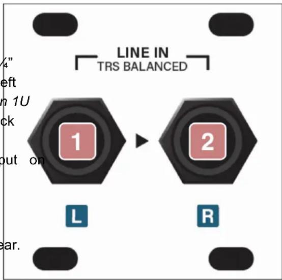
text_image
LINE IN TRS BALANCED 1 2 L R2. LINE IN (R)
An external signal patched into this 14 " TRS jack is passed through to the right channel of a connected Stereo Line In 1U module, where it's amplified to eurorack levels and made available to other eurorack modules via the right 18 " output on the Stereo Line In 1U module.
This input supports both professional, balanced +4 dBu equipment and prosumer, unbalanced -10 dBV level gear.
Technical Specifications
Stereo Line In 1U
| Width | 12 hp |
| Maximum Depth | 38 mm |
| Current Draw | 18 mA @ +12V | 12 mA @ -12V |
| Maximum Balanced Input Line Level | +13dbU |
| Maximum Gain | 15db |
Stereo In Jacks 1U
| Width | 8 hp |
| Maximum Depth | 39 mm |
| Current Draw | 0 mA (passive module) |