
Airpeak S1 - Drone SONY - Free user manual and instructions
Find the device manual for free Airpeak S1 SONY in PDF.


| Product Type | Drone (Quadcopter) |
| Model | Airpeak S1 |
| Brand | Sony |
| GNSS Support | Yes (Global Navigation Satellite System) |
| Vision Positioning | Yes, using stereo cameras |
| Obstacle Detection | Multi-directional via stereo cameras and infrared range sensors |
| Flight Modes | Std (Speed), Vel (Velocity), Alt (Altitude) |
| Automated Flight | Yes, using Airpeak Base missions and flight logs |
| Return to Home (RTH) | Yes, automatic on low battery or signal loss |
| Emergency Motor Stop | Yes, by moving both control sticks inward/downward or outward/downward |
| Max Wind Resistance | 20 m/s (66 ft/s) |
| Operating Temperature | -10°C to 40°C (14°F to 104°F) |
| Battery Type | Rechargeable lithium-ion battery pack (two required) |
| Remote Controller | Included with built-in battery and mobile device holder |
| Camera Compatibility | Sony Alpha mirrorless cameras with full-frame sensor (sold separately) |
| Gimbal | 3-axis gimbal (sold separately) |
| Propeller Types | CW (silver hub) and CCW (black hub), not foldable |
| Landing Gear | Attachable, with automatic or manual control |
| Mobile App | Airpeak Flight (control) and Airpeak Base (planning and logs) |
| Maintenance | Calibrate compass, IMU, stereo cameras; clean with dry cloth; update software |
| Package Contents | Aircraft, remote controller, battery packs (2), battery charger, AC adapters, cables, calibration board, landing gear, propellers, startup guide, warranty |
| Safety Features | Geofencing, UTM-regulated zones, user-specified zones, obstacle avoidance, low battery RTH |
Frequently Asked Questions - Airpeak S1 SONY
User questions about Airpeak S1 SONY
0 question about this device. Answer the ones you know or ask your own.
Ask a new question about this device
Download the instructions for your Drone in PDF format for free! Find your manual Airpeak S1 - SONY and take your electronic device back in hand. On this page are published all the documents necessary for the use of your device. Airpeak S1 by SONY.
USER MANUAL Airpeak S1 SONY
natural_image
Black quadcopter drone with mounted camera and propeller (no visible text or symbols)This manual explains the basic usage of ARS-S1.
Operating an aircraft in the United States is subject to federal law and regulations. State and local ordinances may also apply to certain operations. When operating an aircraft, it is the remote pilot/operator's responsibility to always comply with applicable laws, regulations, and ordinances.
Before first use
About this product
Introduction
Supported mobile devices
Supported cameras and lenses
Package contents
Guide to parts and controls
Parts and controls (Aircraft)
Detection range of the infrared range sensors and stereo cameras
Parts and controls (Remote controller)
Parts and controls (Gimbal (sold separately))
Using the dedicated apps
Using the "Airpeak Base" App
Features of the "Airpeak Base" App
Using the "Airpeak Flight" App
Installing the "Airpeak Flight" App
Signing in to the "Airpeak Flight" App
Features of the "Airpeak Flight" App
Getting ready
Preparing the batteries
Charging the batteries
If you cannot charge the aircraft battery pack
Loading battery packs in the aircraft
Preparing the aircraft
Connecting cables to the aircraft
Attaching the damping plate to the aircraft
Attaching landing gear
Attaching the propellers
Preparing the gimbal and a camera
Mounting the gimbal on the aircraft
Configuring settings on the camera
Mounting a camera on the gimbal
Connecting cables between the camera and gimbal
Adjusting the balance of the gimbal
Adjusting the gimbal parameters
Preparing the remote controller
Attaching a mobile device to the remote controller
Cautions when using the remote controller
Linking the aircraft and remote controller
Configuring various settings before flights
| Setting the flight mode |
| Selecting the wireless channel |
| Controlling the aircraft with two remote controllers (dual operation mode) |
| Selecting the operating mode of the control sticks |
| Adjusting the sensitivity of the control sticks |
| Changing the functions assigned to the custom buttons, lever, or dial on the remote controller |
| Configuring the gimbal settings |
| Checking settings before flights |
Flight precautions
Operator's responsibilities
Flight environment
Airspace flight-restricted functions
Preflight checks
Precautions during flights
Making a flight plan
Creating projects and missions
| Setting the flight area for a project |
| Setting geofences |
| Setting a flight path (mission) |
Viewing flight logs
Creating a new mission using a flight log
Turning the power on/off
Turning the aircraft on/off
Turning the remote controller on/off
Controlling the aircraft
Relationship between the remote controller and the flight screen
Parts for flight operations
Switching views on the flight screen
Controlling the aircraft with the remote controller (manual flight)
Flying the aircraft along a set path (automated flight)
Flying the aircraft again along a previous flight path (automated flight)
Returning the aircraft to the Home Point (RTH (Return to Home))
Landing gear operation
Executing an emergency motor stop
Shooting
Relationship between the remote controller and the flight screen
Parts for shooting operations
Maintaining the devices
Checking the status of the devices
Calibrating the sensors of the aircraft
Calibrating the remote controller
Updating the system software
Before disposing of this product
Precautions
General Information
Troubleshooting
Trademarks and copyrights
5-027-737-11(1) Copyright 2021 Sony Group Corporation
Introduction
This product is an aircraft system that realizes dynamic and stable remote photography and videography. With a full-frame mirrorless Sony Alpha camera (sold separately; hereafter, “camera”) equipped, you can capture high-quality images in aerial photography and videography.
Sony is not liable or responsible for any experience, including but not limited to videography, photography, content, income, fees, and/or other compensation associated with or related to the use and/or misuse of the aircraft, its parts, and/or accessories including hardware and software.
Highlights
Agile flying performance and control that unleashes the potential of cameras
Capture impressive, dynamic images from an agile aircraft with intuitive control.
Expands possibilities in aerial photography
Stable flight even in strong wind or where GNSS (Global Navigation Satellite System) signals are weak or unavailable. Multi-directional sensors assist in obstacle detection and braking.
Streamlines workflows with automation
Create sophisticated flight plans with the web app “Airpeak Base.” Besides automated flights based on flight plans, you can use past flight logs to automatically fly the same routes you have flown.
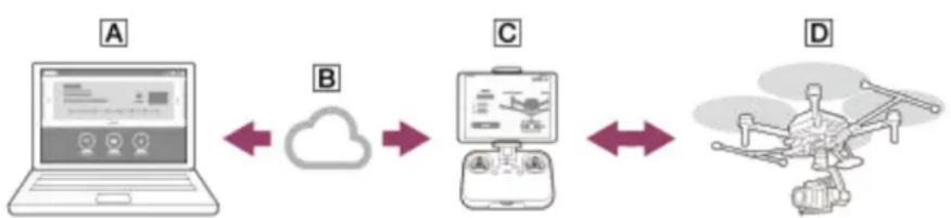
System configuration
This product consists of the following:
Aircraft
A camera can be mounted using a 3-axis gimbal (sold separately; hereafter, "gimbal")
Remote controller/dedicated mobile app "Airpeak Flight"
Install the "Airpeak Flight" App to your mobile device (tablet or smartphone) and attach your mobile device to the remote controller. After completing the process of linking the remote controller and aircraft, you can operate the aircraft, gimbal, and camera (the latter two both sold separately). On the "Airpeak Flight" App screen, you can check the flight distance and battery level, perform various operations, and change settings.
This data and information is synchronized between the “Airpeak Base” and “Airpeak Flight” Apps while your mobile device is connected to the cloud.
Dedicated web app "Airpeak Base"
"Airpeak Base" is a dedicated cloud-based web application that can be used on a computer or iPad to manage devices, plan flights, and view flight logs.
flowchart
graph LR
    A["Laptop with icons"] <--> B["Cloud"]
    B --> C["Drone with drone icon"]
    C <--> D["Drones"]
A Web app "Airpeak Base"-ready computer or iPad:
Manage the devices, plan flights, and view flight logs.
B Cloud
C Mobile app "Airpeak Flight"-ready remote controller:
Control the aircraft and a gimbal/camera (both sold separately).
D Aircraft:
Equip with a camera (sold separately) on the aircraft using a gimbal (sold separately).
Note
- “Airpeak Flight,” “Airpeak Base,” “Airpeak Plus,” and any other Airpeak or third-party network services, content, operating systems, or software are subject to terms and conditions and may be changed, interrupted, or discontinued at any time. Fees, registration, and credit card information may also be required.
- Screen images and illustrations in this Help Guide (web manual) may vary from the actual product.
- Design and specifications are subject to change without notice.
5-027-737-11(1) Copyright 2021 Sony Group Corporation
SONY
Help Guide
Airpeak S1
ARS-S1
Supported mobile devices
Visit the support site for details on mobile devices you can use.
https://electronics.sony.com/airpeak/support/compatibility
5-027-737-11(1) Copyright 2021 Sony Group Corporation
SONY
Help Guide
Airpeak S1
ARS-S1
Supported cameras and lenses
Visit the support site for details on camera bodies and lenses you can use.
https://electronics.sony.com/airpeak/support/compatibility
5-027-737-11(1) Copyright 2021 Sony Group Corporation
SONY
Help Guide
Airpeak S1
ARS-S1
Package contents
Contact the place of purchase or Sony Customer Support if any components are missing. Quantities are indicated in parentheses.
Note
- Please retain the cushionings as they will be used when assembling the aircraft.
Bottom cushioning
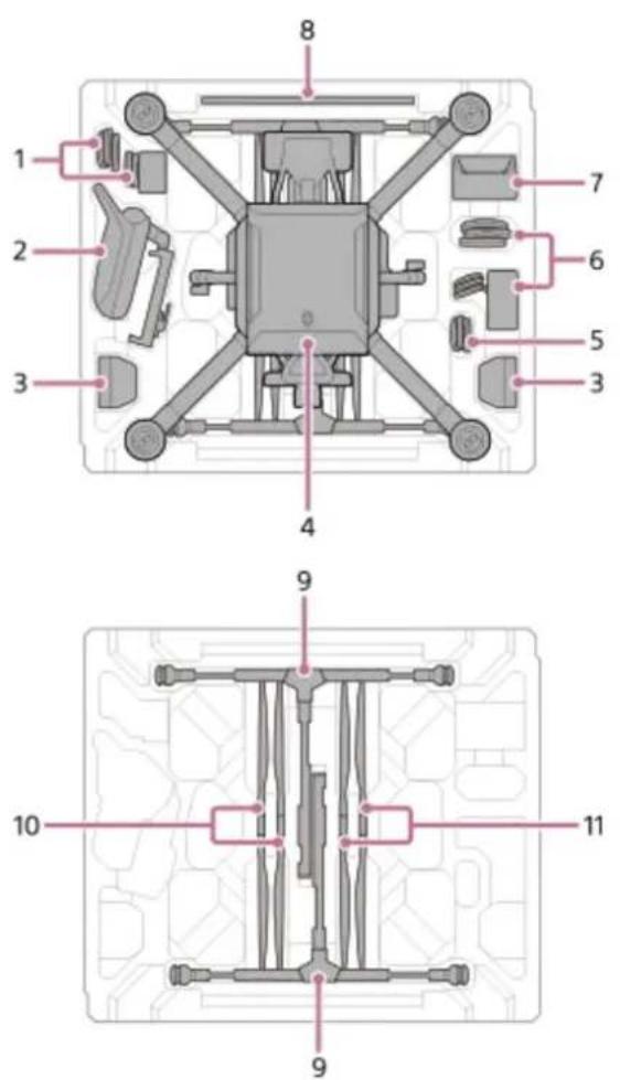
Top cushioning

natural_image
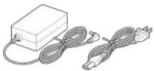
Pure technical diagram of a rectangular component with internal structure and circular features, no text or symbols presentAC adapter for remote controller (1)/power cord (1)1.
natural_image
Illustration of a rectangular device connected to two cables, one with a plug and the other with a plug (no text or symbols visible)- Remote controller (1)
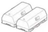
- Battery pack (2)
- Aircraft (1)

natural_image
Line drawing of a four-legged drone with four propellers and a central body (no text or symbols)- Cables
• Power cable (aircraft — gimbal) (1)

• Control cable (aircraft — gimbal) (1)

• USB Type-C ^® cable (aircraft — gimbal) (1)

• Micro USB cable (gimbal — camera) (1)

(a) Micro USB
• USB Type-C ^® cable (gimbal — camera) (1)

(b) USB Type-C®
- AC adapter for battery charger (1)/power cord (1)

natural_image
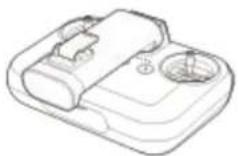
Illustration of a rectangular electronic device connected to two coiled cable arrays (no text or symbols)- Battery charger (1)

- Calibration board (1)

- Landing gear (2)
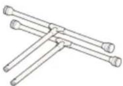
natural_image
Line drawing of three intersecting cylindrical rods (no text or symbols)- Propeller (CW: clockwise rotation) (2) (*1)

(c) Hub: silver
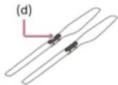
- Propeller (CCW: counterclockwise rotation) (2) (*1)
natural_image
Diagram of two elongated biological structures with internal dark components, labeled (d), and a pink arrow pointing to one structure (no text or symbols beyond label)(d) Hub: black
Startup Guide (1)/Warranty (1)12.
*1 Not capable of being folded
Gimbal set (sold separately)
Gimbal (1)
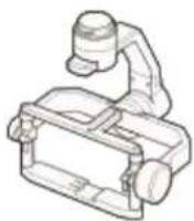
• Damping plate (1) ^(*1)
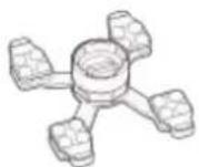
Hot shoe adapter (1)
• Top camera screw (1)
- Camera plate (1)
• Micro USB cable (gimbal — computer) (1)
• Hot shoe extension (1)
• Hex screw (10) (including two spare screws)
- Hex wrench (1)
*1 Quick-release is preinstalled.
Parts and controls (Aircraft)
The locations of the parts and controls of the aircraft are shown below.
Front

Rear
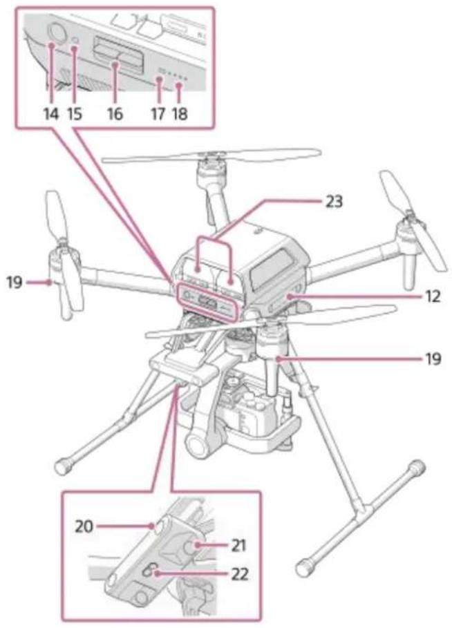
- Upward infrared range sensor
Detects objects above and measures the distance to them.
Propellers2.
Motors3.
- Flight status LEDs (Front LEDs)
Light up in red while the aircraft is turned on to indicate the front direction.
Antennas (built-in)5.
Frame arms6.
- FPV gimbal camera
Images from this camera are displayed in the FPV view in the "Airpeak Flight" App.
- Forward-facing stereo camera
Detects objects in front and measures the distance to them.
Camera (sold separately)9.
Landing gear10.
Gimbal (Main gimbal) (sold separately)11.
- Side-facing stereo cameras
Detect objects on the left and right and measure the distance to them.
GNSS (Global Navigation Satellite System) antenna (built-in)13.
- ⏻ (Power) button
Press and hold for 2 seconds to turn the aircraft on or off.
15. LINK button
Press to link the aircraft and the remote controller.
BATTERY RELEASE levers16.
17. Power status LED
Indicates the status of the aircraft.
| LED color LED indication Status of the aircraft | ||
| Green Lit up Turned on | ||
| Cyan Lit up Receiving system software data. | ||
| Green, red, and yellow Blinking alternately Updating system software. | ||
18. Battery level LEDs
Indicate the remaining battery level of the battery packs loaded in the aircraft.
| LED indication Remaining battery level | |
| All lit up Full | |
| Three lit up Approx. 75% | |
| Two lit up Approx. 50% | |
| One lit up Approx. 25% | |
| Blinking fast Low | |
| Off None | |
19. Flight status LEDs (Rear LEDs)
Indicate the status of the aircraft.
Status notifications
| LED color LED indication Status of the aircraft | ||
| Green, yellow, and red | Blinking alternately | The aircraft is starting up. |
| Green | Blinking slowly | GNSS (Global Navigation Satellite System) signals are being used for positioning. |
| Green | Blinking twice repeatedly | The Vision Positioning is being used for positioning. |
| Yellow | Blinking slowly | The aircraft is flying with [Flight mode] set to [Alt (Altitude)]. |
| Blue | Blinking fast | The brakes have been activated to avoid obstacles. |
| Blue | Blinking slowly The aircraft is performing automated flight. | |
| Cyan | Blinking twice repeatedly | The aircraft is waiting for the completion of linking with the remote controller. |
Warning notifications
| LED color LED indication | Status of the aircraft |
| LED color LED indication Status of the aircraft | ||
| Yellow Blinking twice repeatedly The signal from the remote controller has been lost. | ||
| Red Blinking twice repeatedly The battery level of the aircraft is low. | ||
| Red Blinking fast The battery level of the aircraft is almost depleted. | ||
| Red Lit up A fatal error has occurred. If the aircraft is in flight, land it immediately. |
- Backward-facing stereo camera
Detects objects to the rear and measures the distance to them.
- Downward-facing stereo camera
Detects objects below and measures the distance to them.
- Downward infrared range sensor
Detects objects below and measures the distance to them.
Battery packs23.
Related Topic
• Connecting cables to the aircraft
- Attaching the damping plate to the aircraft
- Attaching landing gear
- Attaching the propellers
- Setting the flight mode
• Turning the aircraft on/off
• Calibrating the sensors of the aircraft
5-027-737-11(1) Copyright 2021 Sony Group Corporation
SONY
Help Guide
Airpeak S1
ARS-S1
Detection range of the infrared range sensors and stereo cameras
The aircraft is equipped with two infrared range sensors and five stereo cameras. They enable stable flight and hovering by detecting objects around the aircraft and measuring the distance to them.
Note
• To ensure flight stability and safety, do not block the infrared range sensors or stereo cameras.
Detection range of the infrared range sensors
The detection range of the infrared range sensors is as shown in the illustrations below. Objects in the gray areas in the illustrations are outside the detection range, which means they cannot be detected. Be cautious when you fly the aircraft.
Side view (The left side is the front of the aircraft.)

(a) 3 m
(b) 15^
(c) 100 mm
Rear view

(a) 3 m
(b) 15^
(c) 100 mm
Detection range of the stereo cameras
The detection range of the stereo cameras is as shown in the illustrations below. Objects in the gray areas in the illustrations are outside the detection range, which means they cannot be detected. Be cautious when you fly the aircraft.
Front view

(a) 80^
(b) 54 m
Side view (The left side is the front of the aircraft.)
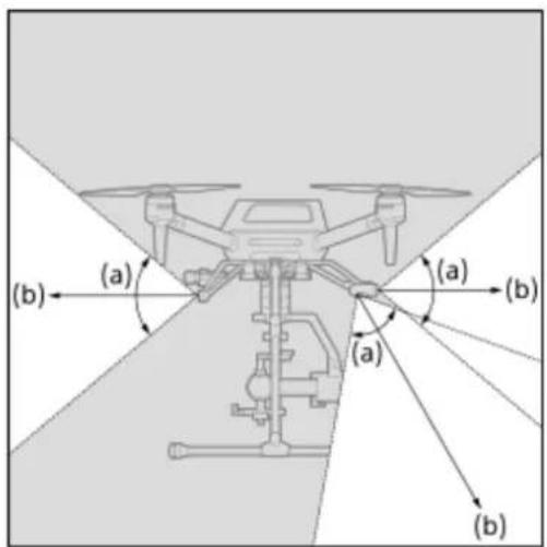
(a) 80^
(b) 54 m
Top view
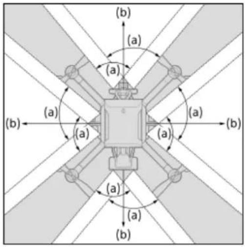
(a) 80^
(b) 54 m
Related Topic
• Parts and controls (Aircraft)
• Calibrating the sensors of the aircraft
5-027-737-11(1) Copyright 2021 Sony Group Corporation
Parts and controls (Remote controller)
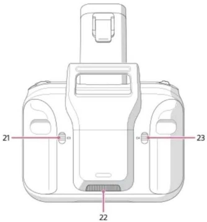
The locations of the parts and controls of the remote controller are shown below.

1. Status LED
Indicates the status of the remote controller.
| LED color LED indication Status of the remote controller | ||
| None Off Turned off | ||
| Green Lit up | Not connected to the aircraft | |
| Blue Lit up | Connected to the aircraft as the main controller | |
| Purple Lit up | Connected to the aircraft as the sub controller | |
| Green | Blinking slowly at an interval of 6 seconds | In a standby state |
| Red Blinking | An error has occurred in the remote controller. | |
| Yellow Blinking | There has been no operation for more than 5 minutes. The remote controller will enter a standby state if you leave it without performing any operation. | |
| Cyan Lit up | In the system software transfer mode | |
| Cyan | Blinking twice repeatedly | Waiting for the completion of linking with the aircraft. |
| Green, red, and yellow | Blinking alternately Updating system software | |
2. (Automated flight pause) button
Press to pause the aircraft's movement during automated flight.
(Power) button3.
| Operation | Result |
| Press and hold for 2 seconds | The remote controller turns on. |
| Operation Result | |
| Press and hold for 5 seconds The remote controller turns off. | |
| Press and hold for 2 seconds while the remote controller is turned on | The remote controller enters a standby state. Press and hold for 2 seconds once again to wake it up from the standby state. |
| Press and hold for 10 seconds The remote controller is forcibly turned off. | |
Power port4.
5. (MOVIE) button
Press to start/stop video recording.
6. Battery level LEDs
Indicate the remaining battery level of the remote controller.
| LED indication Remaining battery level | |
| All lit up Full | |
| Three lit up Approx. 75% | |
| Two lit up Approx. 50% | |
| One lit up Approx. 25% | |
| Blinking fast Low | |
| Off None | |
7. Control sticks
Control the aircraft and gimbal (sold separately).
8. Lever heads
The lever heads of this product are compatible with the following product.
• Manufacturer: Futaba Corporation
• Part Number: EBT2277
• Part Name: Gold Stick Ends
URL: https://futabausa.com/product/ebt2277/
9. Mobile device holder
Mount the mobile device on which you have installed the "Airpeak Flight" App.
HDMI port10.
11. USB port (USB-A)
Connect a USB cable to this port and to the mobile device attached to the mobile device holder.
Micro USB port (USB-B)12.
13. Handle bar
An antenna for wireless transmission is built in. Be careful not to cover the antenna part with your hand or cables.
14. Control lever
Tilts the gimbal (up/down).
15. Flight mode switch
Selects the flight mode.
16. Air vent
Do not block the air vent with your hand or other objects while using the remote controller.
17. C1 (Custom 1) button
Assign the desired function to this button in the setting menu of the "Airpeak Flight" App. By default, you can take a photo by pressing this button.
18. C2 (Custom 2) button
Assign the desired function to this button in the setting menu of the "Airpeak Flight" App. By default, you can adjust the ISO sensitivity (recommended exposure index) of the camera (sold separately) by turning the control dial after pressing this button.
19. Control dial
Adjusts the aperture value (F-value) of the camera.
Antenna (built-in)20.
21. C3 (Custom 3) button
Assign the desired function to this button in the setting menu of the "Airpeak Flight" App. The following functions are assigned by default:
- Adjust the shutter speed of the camera by turning the control dial after pressing this button.
- Tilt the FPV gimbal (up/down) by moving the control lever while pressing this button.
- Reset the FPV gimbal position by pressing this button twice.
22. Air inlet
Do not block the air inlet with your hand or other objects while using the remote controller.
23. C4 (Custom 4) button
Assign the desired function to this button in the setting menu of the "Airpeak Flight" App. The following functions are assigned by default:
- Change the focus mode setting of the camera by turning the control dial after pressing this button.
- Pan the main gimbal (left/right) by moving the control lever while pressing this button.
- Reset the main gimbal position by pressing this button twice.
Related Topic
- Attaching a mobile device to the remote controller
• Cautions when using the remote controller - Controlling the aircraft with two remote controllers (dual operation mode)
- Changing the functions assigned to the custom buttons, lever, or dial on the remote controller
• Turning the remote controller on/off
• Parts for flight operations
• Parts for shooting operations
• Calibrating the remote controller
Parts and controls (Gimbal (sold separately))
The locations of the parts and controls of the gimbal (sold separately) are shown below.

Pan motor1.
Pan adjustment2.
Tilt top bar3.
Tilt vertical adjustment4.
Tilt front-back adjustment5.
Tilt motor6.
Roll motor7.
Top camera screw8.
Status LED9.
LED color LED indication Status of the gimbal
| LED color | LED indication Status of the gimbal | |
| Red Lit up | An error has occurred in the motor or IMU (*1). | |
| White Blinking Under calibration | ||
| White Lit up | Starting the motor or IMU. | |
| Yellow Blinking The motor or IMU is in a standby state. | ||
| Green Blinking | In the lock mode (*2) | |
| Green Lit up | In the follow mode (*3) | |
| Blue Blinking The gimbal is starting up, so it cannot accept remote operations. | ||
| Purple Blinking Being operated remotely | ||
*1 IMU: Inertial Measurement Unit
*2 Lock mode: The camera orientation (shooting direction) will remain the same even if the aircraft turns.
*3 Follow mode: The camera orientation (shooting direction) follows the panning (left/right) movement of the aircraft.
Roll adjustment10.
AUX port11.
USB port12.
Related Topic
• Mounting the gimbal on the aircraft
- Mounting a camera on the gimbal
- Connecting cables between the camera and gimbal
• Adjusting the balance of the gimbal
• Adjusting the gimbal parameters
- Configuring the gimbal settings
5-027-737-11(1) Copyright 2021 Sony Group Corporation
SONY
Help Guide
Airpeak S1
ARS-S1
Features of the "Airpeak Base" App
"Airpeak Base" is a dedicated web application for managing devices, planning flights, viewing flight logs, and more. It is available from browsers on a computer or iPad.
https://base.airpeak.sony.com/
You can also take advantage of the "Airpeak Plus" cloud service for greater convenience. For detailed information on the cloud service, visit the product page.
https://electronics.sony.com/airpeak/p/arss1/
Note
To use the "Airpeak Base" App, you must accept the terms of use and privacy policy.
- "Airpeak Flight," "Airpeak Base," "Airpeak Plus," and any other Airpeak or third-party network services, content, operating systems, or software are subject to terms and conditions and may be changed, interrupted, or discontinued at any time. Fees, registration, and credit card information may also be required.
The "Airpeak Base" App Home page
The items displayed on the App Home page are described below. Some functions of this app may include paid services.
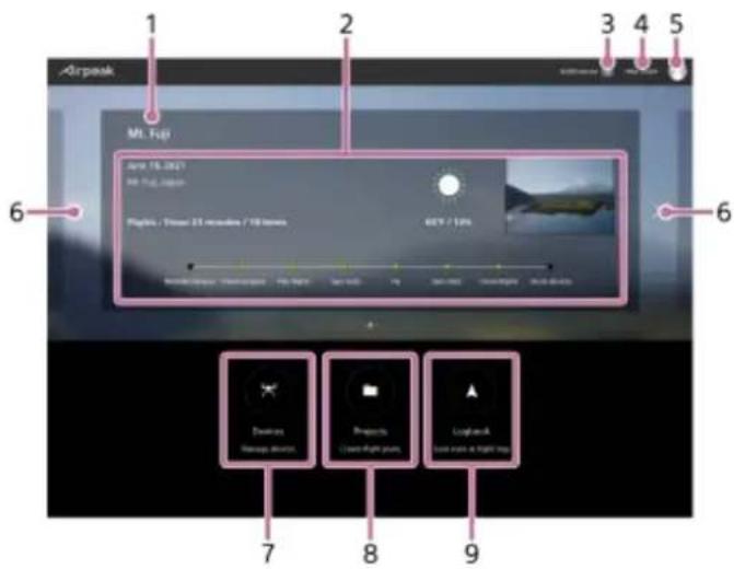
Project name1.
- Project information
Displays information such as flight date, flight duration, meteorological info, progress, etc.
[Notifications]3.
- [Help Guide]
Click to view this Help Guide.
- Account icon
Click to display the menu. You can edit your profile, change units and plans, etc.
- < / (Project selection)
Switches the project displayed on the App Home page.
7. [Devices]
Click to display the [Devices] screen. Based on the log information from the "Airpeak Flight" App, the aircrafts and remote controllers used for flights are automatically displayed and can be managed.
8. [Projects]
Click to display the [Projects] screen. You can manage a flight plan consisting of multiple missions and geofences as a project.
9. [Logbook]
Click to display the [Logbook] screen. You can check flight logs that record the flight path, speed, meteorological info, etc. of past flights.
Related Topic
- Setting the flight area for a project
- Setting geofences
- Setting a flight path (mission)
• Viewing flight logs - Creating a new mission using a flight log
5-027-737-11(1) Copyright 2021 Sony Group Corporation
Installing the "Airpeak Flight" App
Before using this product, you will need to download and install the dedicated app "Airpeak Flight" on your mobile device. The "Airpeak Flight" App is available for downloading and installation as shown below.

https://electronics.sony.com/airpeak/mobileapp
Note
- To use the "Airpeak Flight" App, you must accept the terms of use and privacy policy. Carefully read and agree to the terms of use and privacy policy displayed during the initial setup process before proceeding.
- "Airpeak Flight," "Airpeak Base," "Airpeak Plus," and any other Airpeak or third-party network services, content, operating systems, or software are subject to terms and conditions and may be changed, interrupted, or discontinued at any time. Fees, registration, and credit card information may also be required.
Related Topic
Features of the "Airpeak Flight" App
5-027-737-11(1) Copyright 2021 Sony Group Corporation
Signing in to the "Airpeak Flight" App
A Sony account and an internet connection are required when setting up the aircraft.
1 Start the "Airpeak Flight" App.
The initial setup screen is displayed. Tap [Next] to begin the initial setup process.
2 Follow the on-screen instructions to create a Sony account.
After you submit a request to create a new account with the basic information you entered, such as your user ID (email address) and password, you will receive a message by email for email address validation. Follow the instructions in the email to finish creating the account.
You can also sign in with a Sony account if you have one.
3 Sign in to the "Airpeak Flight" App.
Sign in with the user ID and password you specified when creating your account. After signing in, follow the on-screen instructions to set up the remote controller and aircraft.
5-027-737-11(1) Copyright 2021 Sony Group Corporation
Airpeak S1
ARS-S1
Features of the "Airpeak Flight" App
"Airpeak Flight" is an application that allows you to manage the operations and settings of the aircraft, remote controller, and camera (sold separately) in an integrated way.
It supports a wide range of operations, from checking the status of the aircraft such as the flight distance and remaining battery power to changing the settings of the camera in the sky. In addition to manual flight, automatic flight can also be set. During a mission flight, you can check the flight path, execute the mission, and check the status of the aircraft and other devices in flight with this app.
The display examples in this Help Guide are for when using a tablet device.
Screen flow of the "Airpeak Flight" App

flowchart
graph TD
    A["Input: Airpeak 1"] --> B{Check}
    B --> C["Processing: Battery"]
    C --> D["Output: Airpeak 2"]
A App Home page
This page is displayed when you start the app. When you launch the app for the first time, the initial setup screens are displayed before the App Home page is displayed.
B Flight screen
You can perform the flight and shooting operations. The items displayed on the screen change depending on the usage conditions and settings.
C Setting menu
You can configure the aircraft, remote controller, camera, gimbal, and "Airpeak Flight" App.
App Home page

- [Airpeak Base]
Tap to launch the "Airpeak Base" App in your browser.
- Account icon
Check the account information for sign-in from the menu displayed by tapping this icon.
- Update notifications
Notify when updates to the system software, airspace database system, etc. are required before flight.
- Connection status of the devices
Displays the connection status of the aircraft and remote controller.
- Project information
Displays the project name and flight location of the selected project. The project selection screen appears when you tap on the information.
- [Start flight]
Tap to display the flight screen. [Show flight screen] is displayed instead in cases such as when the aircraft, remote controller, or "Airpeak Flight" App is not connected.
Related Topic
• Installing the "Airpeak Flight" App
• Signing in to the "Airpeak Flight" App
- Relationship between the remote controller and the flight screen
• Updating the system software
5-027-737-11(1) Copyright 2021 Sony Group Corporation
Charging the batteries
Before using this product, charge the aircraft battery packs and built-in remote controller battery.
Charging the aircraft battery packs
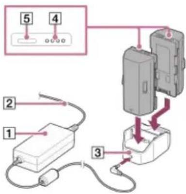
Connect the power cord (2to the AC adapter for battery charger ().1)
Connect the AC adapter to the power port (3) of the battery charger.2.
- Place the battery packs in the battery charger.
The battery charger can hold two battery packs and will charge the second one after the first one is charged. Both cannot be charged at the same time.
- Firmly insert the plug of the power cord (2) into the wall outlet.
The battery level LEDs of the battery pack (4) flash during charging and go off when the battery pack is fully charged.
To check the battery level
You can check the battery level by pressing the battery level button on each battery pack (5).
Note
It may take about 20 seconds before charging begins. Wait until the battery level LEDs start flashing.
- A safety mechanism prevents charging when battery packs are hot or cold. Charging begins automatically once battery packs can be charged at room temperature.
- If the difference between the remaining battery level in the two battery packs is 20% or more, the aircraft motor will not start.
Charging the built-in remote controller battery

Connect the power cord (2) to the AC adapter for remote controller (1).
Open the power port cover of the remote controller and connect the AC adapter to the power port (3).2.
- Firmly insert the plug of the power cord (2) into the wall outlet.
The battery level LEDs (4) flash during charging and go off when the battery is fully charged.
To check the battery level
You can check the battery level by pressing the ⏻ (Power) button on the remote controller once.
Related Topic
• If you cannot charge the aircraft battery pack
- Loading battery packs in the aircraft
5-027-737-11(1) Copyright 2021 Sony Group Corporation
SONY
Help Guide
Airpeak S1
ARS-S1
If you cannot charge the aircraft battery pack
All of the battery level LEDs on the battery pack may blink or stay turned off when the battery pack is first charged in cases such as the following. If this happens, remove the battery pack from the battery charger and then recharge it.
• Immediately after purchase
• The battery pack has been left for a long time.
- The battery pack has been left inserted into a device for a long time.
Note that if all of the battery level LEDs blink or stay turned off even when the battery pack is charged for a second time, a battery pack or battery charger abnormality may have occurred. Stop using them and contact your Sony dealer.
Related Topic
- Charging the batteries
5-027-737-11(1) Copyright 2021 Sony Group Corporation
Loading battery packs in the aircraft
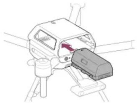
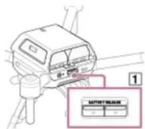
Load the two battery packs in battery slots 1 and 2 at the rear of the aircraft.
1 Load the battery packs in the aircraft.
Insert firmly until the battery packs click and lock into place.
natural_image
Technical line drawing of a mechanical device with a highlighted component (no text or symbols)2 Confirm that the battery packs are loaded correctly.
Battery packs are not loaded correctly if a yellow line (2) is visible and the BATTERY RELEASE lever (1) has not returned to the original position. Firmly insert battery packs all the way in.
Loaded correctly
Loaded incorrectly
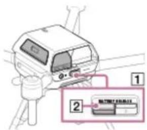
Hint
- Battery levels can be checked by pressing the battery level button on each battery pack. Before flights, be sure to confirm that the battery levels are enough for the flights you have planned.
• To unload a battery pack, press the BATTERY RELEASE lever and remove it.
Related Topic
- Charging the batteries
5-027-737-11(1) Copyright 2021 Sony Group Corporation
Connecting cables to the aircraft

Remove the top cushioning (1) from the outer box and place it on a flat surface. Holding the aircraft securely by the frame arms (2), place it upside down on the cushioning.
Be careful to keep the propeller attachment points (3) of each motor off the surface.


Connect the cables to the connection hub on the aircraft.
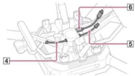
4 Control cable (aircraft — gimbal)
5 Power cable (aircraft — gimbal)
6 USB Type-C ^® cable (aircraft — gimbal)
Front of aircraft

- Connect the control cable (aircraft — gimbal) (4to the control port ( ). 7 Insert fully until the plug locks into place.
Rear of aircraft
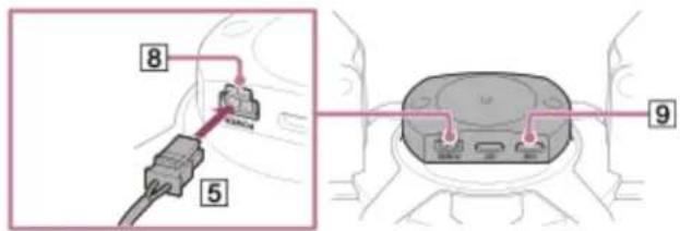
- Connect the power cable (aircraft — gimbal) (15 to the POWER port ().8 Insert fully until the plug locks into place.
- Connect the USB Type-C® cable (aircraft — gimbal) (6) to the USB port (9) You can also connect the USB Type-C® cable (aircraft—gimbal) to the EXT port.
Related Topic
- Attaching the damping plate to the aircraft
5-027-737-11(1) Copyright 2021 Sony Group Corporation
Attaching the damping plate to the aircraft
The damping plate (with the quick-release pre-installed), hex wrench, and hex screws are included in the gimbal set (sold separately).
1 Attach the damping plate to the aircraft.
- Perform the operations described in "Connecting cables to the aircraft."
- Orient the damping plate so that the quick-release arrow (1) surface faces down and the arrow points toward the front of the aircraft.
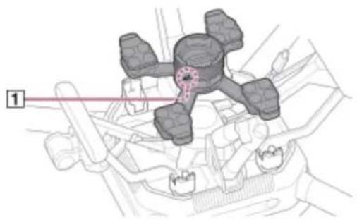
natural_image
Mechanical component diagram showing a lever mechanism with no visible text or symbols-
While maintaining the same orientation, place the damping plate on the attachment points of the aircraft.
-
Use the hex wrench (H2.5 mm) and hex screws included in the gimbal set (sold separately) to attach the damping plate at two positions on each leg (eight in total).

natural_image
Technical line drawing of a mechanical assembly with no visible text or symbols2 Insert the plugs at the other ends of the cables connected to the aircraft in the corresponding quick-release ports.

② Control cable (aircraft — gimbal)
③ Power cable (aircraft — gimbal)
4 USB Type-C ^® cable (aircraft — gimbal)
Front of aircraft

- Connect the control cable (aircraft — gimbal) (2to the control port ( ). 5 Insert fully until the plug locks into place.
Rear of aircraft
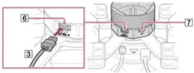
- Connect the power cable (aircraft — gimbal) (3 to the POWER port ().6 Insert fully until the plug locks into place.
- Connect the USB Type-C® cable (aircraft — gimbal) (4) to the USB port (7).
Note
- Tighten the screws firmly using the hex wrench included in the gimbal set (sold separately). Otherwise, the screws may loosen and detachment may occur during flight.
- When using tools other than the hex wrench included in the gimbal set (sold separately), be sure to tighten the screws with a torque of 1.5 ± 0.5 Nm.
Related Topic
• Mounting the gimbal on the aircraft
SONY
Help Guide
Airpeak S1
ARS-S1
Attaching landing gear
1 Perform the operations described in "Attaching the damping plate to the aircraft."
2 Press in the ball detent (1) and insert the landing gear.
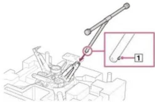
Make sure that the ball detent (☐) is fully engaged.
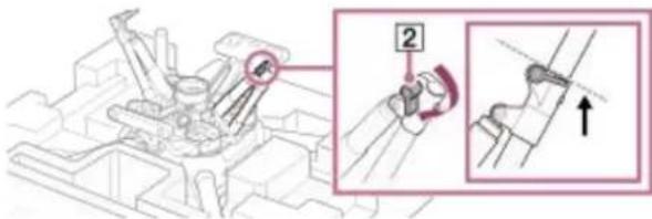
3 Turn the lever (2) to lock the landing gear.
Turn both landing gear levers (2) below the dotted line as shown below.

4 Repeat steps 2 and 3 to attach the other landing gear.
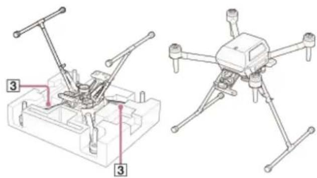
5 Turn the aircraft over.
Holding the aircraft securely by two frame arms (3), turn it over.
natural_image
Technical line drawing of a drone assembly with labeled parts (no text or symbols present)To remove the landing gear
- Remove the top cushioning from the outer box and place it on a flat surface. Holding the aircraft securely by the frame arms, place it upside down on the cushioning. Be careful to keep the propeller attachment points of each motor off the surface.
Turn the landing gear lever (2) to unlock it.2.

Press in the ball detent (1) and remove the landing gear.3.
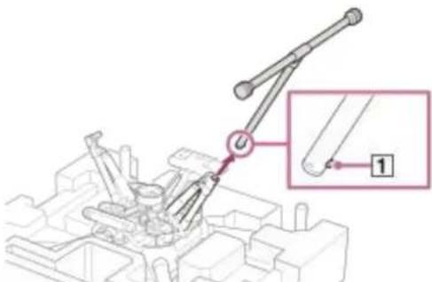
- Turn the landing gear levers (2) until they are positioned in place. When storing the aircraft in the outer box, turn both landing gear levers (2) below the dotted line as shown below.
5-027-737-11(1) Copyright 2021 Sony Group Corporation
SONY
Help Guide
Airpeak S1
ARS-S1
Attaching the propellers
The aircraft uses two types of propellers: clockwise (CW) and counterclockwise (CCW) propellers, which rotate in different directions. Using the hub color as a guide, attach propellers with hubs of the same color. When attaching/removing the propellers, make sure that the aircraft is turned off and be careful not to get injured by the edges.
1 Make sure the aircraft is off.
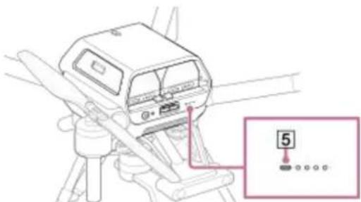
Confirm that the power status LED on the aircraft is off.
2 Check the propeller hub.
Propeller (CW)
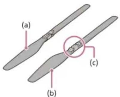
(a) Top side of the propeller
(b) Underside of the propeller
(c) Hub (silver)
Propeller (CCW)

3 Attach the propellers (CW) (1) to the motors with silver hubs.
Place the propeller on the propeller attachment point and turn the propeller counterclockwise until it clicks into place. Hold the motor (2) firmly in place with your other hand to prevent it from turning.

(g) Silver
4 Attach the propellers (CCW) (Bto the motors with black hubs.
Place the propeller on the propeller attachment point and turn the propeller clockwise until it clicks into place. Hold the motor (4) firmly in place with your other hand to prevent it from turning.

(h) Black
Note
- Before each flight, confirm that the propellers are securely attached.
- If you do not hear a clicking sound when attaching the propellers, the propellers may not have been attached properly and pose a risk of crash. Refrain from using the aircraft and contact Sony Customer Support.
- If the metal part of the propeller attachment point does not move smoothly, the propeller may fall off during flight and pose a risk of crash. Refrain from using the aircraft and contact Sony Customer Support.
Before attaching the propellers, make sure that the stickers on the motors are not damaged. If the stickers on the motors are peeled off or the adhesive layers of the stickers are exposed, the propellers may not have been attached properly and pose a risk of crash. Refrain from using the aircraft and contact Sony Customer Support.
To remove the propellers
- Make sure the aircraft is off.
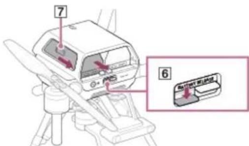
Confirm that the power status LED (5) on the aircraft is off.
- While pressing the BATTERY RELEASE levers (6) push out the projecting parts on the sides of the battery packs (7) in the directions of the arrows to remove both battery packs.
Press the BATTERY RELEASE levers carefully so that the battery packs do not hit your fingers. Battery packs are still hot immediately after use. Handle with care. Also, be careful not to drop the battery packs.
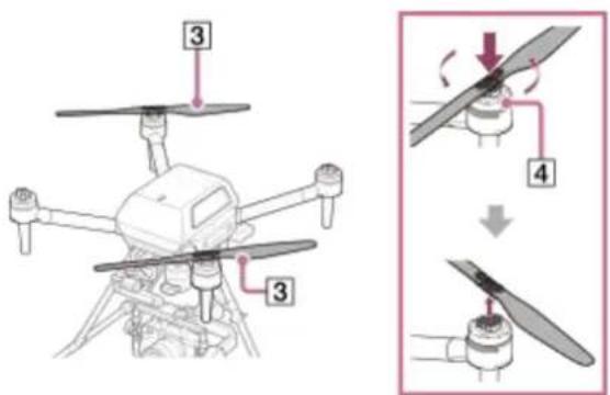
- Remove the propellers (CW) (1).
Press the propeller hub against the metal part of the motor and turn the propeller clockwise to remove it. Hold the motor (2) firmly in place with your other hand to prevent it from turning.

- Remove the propellers (CCW) (3).
Press the propeller hub against the metal part of the motor and turn the propeller counterclockwise to remove it. Hold the motor (4) firmly in place with your other hand to prevent it from turning.
Note
- Be careful not to touch the motor and its surrounding parts as they become hot after use. There is a risk of burns.
SONY
Help Guide
Airpeak S1
ARS-S1
Mounting the gimbal on the aircraft
1 Make sure the aircraft is off.
Confirm that the power status LED (1) on the aircraft is off.

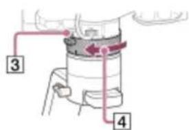
2 With the marks (2) on the gimbal and quick-release aligned, attach the gimbal.

natural_image
Illustration of a drone with attached mechanical components, showing a close-up of the component being inserted (no text or symbols present)3 Turn the ring (4) toward Lock) ().3
Turn the ring until it clicks and locks into place.
To remove the gimbal
Make sure the aircraft is off.1.
- Hold down the gimbal detach button (5) on the quick-release and turn the ring (4) toward (Q)lock). The gimbal will come off the quick-release.

Note
- Hold the gimbal with both hands when removing it. The gimbal or camera may be scratched or damaged if the gimbal rotates or drops.
- Be sure to remove the gimbal after use. Leaving it attached to the aircraft may damage the damping rubber of the damping plate.
Related Topic
- Attaching the damping plate to the aircraft
5-027-737-11(1) Copyright 2021 Sony Group Corporation
SONY
Help Guide
Airpeak S1
ARS-S1
Configuring settings on the camera
Prepare the camera before mounting it on the gimbal. (Both the camera and gimbal are sold separately.) The following is a sample procedure using an ILCE-7SM3 camera.
1 Open the battery cover and insert a battery pack.

natural_image
Diagram of a mechanical component with a highlighted internal section (no text or symbols)2 Open the memory card cover and insert a memory card.
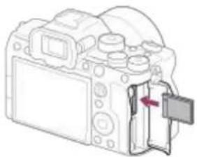
natural_image
Line drawing of a DSLR camera with an open door and a red arrow indicating the left side (no text or symbols present)3 Configure the following setting items on the camera.
For setting instructions, refer to the camera operating instructions or online Help Guide (Web manual).
• [PC Remote Function] – [PC Remote]: [On]
- [PC Remote Function] – [Still Img. Save Dest.]: [Camera Only]
• [Ctrl w/ Smartphone] – [Ctrl w/ Smartphone]: [Off]
• [USB Power Supply]: [Off]
Note
During flights, cameras consume battery power as you shoot. Always charge the camera battery sufficiently before mounting on the gimbal.
- Use memory cards with sufficient free space for recording images.
- Be sure to set the Bluetooth function of the camera to [Off]. If it is set to [On], it may affect the wireless transmission function.
SONY
Help Guide
Airpeak S1
ARS-S1
Mounting a camera on the gimbal
The camera plate, hot shoe adapter, and top camera screw are included in the gimbal set (sold separately).
1 Attach the camera plate (2) to the tripod socket (1) on the bottom of the camera.
Tighten the thumbscrew (3) to secure it firmly.

2 Attach the hot shoe adapter (4) to the camera.

When using a camera with a short height such as the ILME-FX3 or ILCE-7C, attach the hot shoe extension (5 to the hot shoe adapter. The hot shoe extension is included in the gimbal set (sold separately).
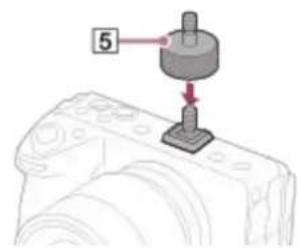
3 Place the camera in the gimbal.
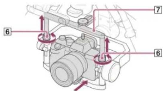
Loosen the locking screws (60 on both sides of the gimbal frame.1.
Extend the tilt top bar (7) to make it higher.2.
- Place the camera in the gimbal from the front. Slide the camera plate attached to the camera into the groove on the bottom part of the frame.
4 Secure the camera in the gimbal.

Lower the tilt top bar (7), and then tighten the locking screws (6) on both sides.1.
Tighten the top camera screw (8) on the hot shoe adapter screw.2.
Tighten the lever (9) on the bottom of the frame to secure the camera.3.
Related Topic
- Configuring settings on the camera
- Connecting cables between the camera and gimbal
5-027-737-11(1) Copyright 2021 Sony Group Corporation
Connecting cables between the camera and gimbal
Use the included USB cable to connect ports on the camera and gimbal.
1 Insert the plug of the included USB Type-C® cable (gimbal — camera) or micro USB cable (gimbal — camera) in the camera USB port (1).
Connect the USB cable that matches your camera port.

natural_image
Technical diagram of a mechanical assembly with labeled component (no text or symbols present)2 Insert the other end of the USB cable connected to the camera in the gimbal USB port (2).
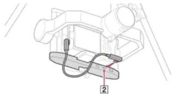
natural_image
Technical line drawing of a mechanical device with labeled component (no text or symbols beyond label)Note
Positions of camera ports vary by camera.
- If you adjust the tilt axis of the gimbal, the USB cable may come into contact with the frame of the gimbal. Route the USB cable so that it does not come into contact with the gimbal frame.
Related Topic
• Mounting a camera on the gimbal
SONY
Help Guide
Airpeak S1
ARS-S1
Adjusting the balance of the gimbal
Adjust the balances of the tilt (1), roll (2) and pan ( ) axes.
Preparation
- Confirm that the camera lens cap is removed.
- Confirm that the camera and gimbal are connected using the USB cable.
- Turn on the camera to avoid movements of the focus unit in the lens.
- Confirm that the aircraft is turned off.
- Confirm that you have installed all the accessories you want to use.
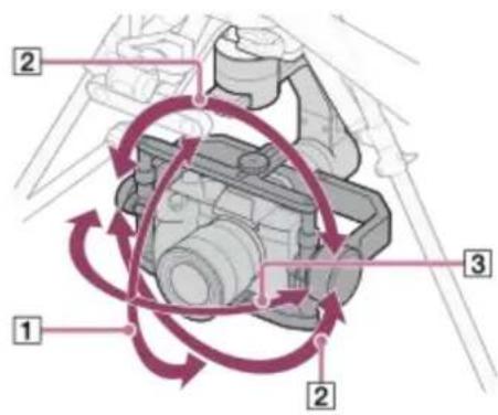
1 Adjust the balance of the tilt axis.
Adjust the horizontal and vertical balances of the tilt axis.
Horizontal balance adjustment of the tilt axis

- Loosen the top camera screw (4) and bottom lever (5) and then slide the camera plate ( ) forward or backward to adjust the balance.
After adjusting the balance, firmly tighten the top camera screw (4) and bottom lever (5). - Rotate the tilt frame (7) by about ±15^ to check if the balance is adjusted properly. If properly adjusted, the tilt frame (7) will stay still or return to the horizontal position.
Vertical balance adjustment of the tilt axis

Rotate the gimbal tilt frame (8to aim the camera lens upward.1.
- Loosen the levers (9) on both sides and slide the tilt frame (8) back and forth to adjust the balance. Adjust so that the left and right adjusters are at the same level.
After adjusting the balance, firmly tighten the levers (9) on both sides.3.
- Rotate the tilt frame (8) by about ±45^ to check if the balance is adjusted properly. If properly adjusted, the tilt frame (8) will stay still.
Adjust the balance of the roll axis.

Loosen the lever (10) and slide the roll frame (11 left and right to adjust the balance.1.
After adjusting the balance, firmly tighten the lever (10).2.
- Rotate the roll frame (11) by about ±45^ to check if the balance is adjusted properly. If properly adjusted, the roll frame (11) will stay still.
Adjust the balance of the pan axis.

Loosen the lever (12) and slide the pan frame (13) back and forth to adjust the balance.1.
After adjusting the balance, firmly tighten the lever (12).2.
- With the gimbal stationary, tilt the aircraft forward, backward, left, and right to check if the balance is adjusted properly.
If properly adjusted, the pan frame (13) will stay still.

natural_image
Diagram showing two identical mechanical devices with articulated arms, one mounted on a tripod and the other on a base, both with directional arrows indicating rotation (no text or symbols present)Note
- Do not adjust the gimbal balance with the aircraft upside down. Doing so may deteriorate or damage the damping rubber of the damping plate.
Related Topic
- Connecting cables between the camera and gimbal
• Adjusting the gimbal parameters
5-027-737-11(1) Copyright 2021 Sony Group Corporation
SONY
Help Guide
Airpeak S1
ARS-S1
Adjusting the gimbal parameters
The gimbal parameters need to be adjusted.
Visit the support site for details on adjustment.
http://electronics.sony.com/airpeak/p/gblt3/settings
5-027-737-11(1) Copyright 2021 Sony Group Corporation
SONY
Help Guide
Airpeak S1
ARS-S1
Attaching a mobile device to the remote controller
On the remote controller, mount the mobile device (tablet or smartphone) on which you have installed the "Airpeak Flight" App.
1 Raise the lever (1) on the back and extend the mobile device holder (2)

2 Place the mobile device on the mobile device holder and adjust the holder height.

natural_image
Illustration of a handheld device with a screen and control buttons, no text or symbols present.3 Lower the lever (1) to secure the mobile device.

4 Stabilize the mobile device holder. Tighten the screw (3) at the base of the holder by turning it with a coin or tool.

5 Connect the cable included with your mobile device to the remote controller USB port (USB-A) (4) and the mobile device port.
If your mobile device did not come with a cable, use another compatible cable.

To mount a smartphone
Raise the smartphone holder (5) in the middle of the mobile device holder, and then mount the smartphone.

Note
- Mobile devices may fall off unless they are correctly secured with the lever.
Related Topic
• Supported mobile devices
5-027-737-11(1) Copyright 2021 Sony Group Corporation
Cautions when using the remote controller
- When using the remote controller to fly an aircraft, turn off the Wi-Fi® and Bluetooth® functions of the tablet or other mobile device mounted on the remote controller.
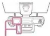
Take care not to cover the parts containing the built-in antennas (a) with your hand, cables, or other objects.
(a)
- Point the handle bar (with built-in antenna) (b) of the remote controller toward the aircraft as shown in the illustrations below.

natural_image
Illustration of a drone with sensor array and a small device, labeled (b), showing no text or symbols beyond the label.
natural_image
Diagram of a drone with a sensor array and a device labeled (b), no text or symbols present.(b) Handle bar (with built-in antenna)
- If you do not operate the remote controller for 5 minutes while it is turned on, an alarm will go off. After another minute, the remote controller will automatically go into a standby state. You can stop the alarm by performing an operation such as moving the control stick, pressing a button, etc.
- If you notice any damage to the remote controller antenna, contact Sony Customer Support. It may not be possible to operate the aircraft.
- You need to link the remote controller and aircraft when you replace the remote controller or are using a new one.
- When you turn off this product, be sure to turn off the aircraft first and then the remote controller. If you turn off the remote controller while the aircraft is still turned on, you will not be able to operate the aircraft in case it moves accidentally. If this happens, it may cause an accident or damage to the aircraft.
Hint
- If wireless communication is disrupted, try turning off Wi-Fi®, Bluetooth®, or other wireless communication functions on your surrounding computers or smartphone.
Related Topic
- Linking the aircraft and remote controller
- Selecting the wireless channel
5-027-737-11(1) Copyright 2021 Sony Group Corporation
Linking the aircraft and remote controller
Follow the on-screen instructions in the “Airpeak Flight” App to link the remote controller and aircraft and set up the aircraft. The aircraft only needs to be set up the first time.
Preparation
- Confirm that the mobile device mounted on the remote controller is connected to the internet.
- Charge the built-in remote controller battery sufficiently.
- Charge both aircraft battery packs sufficiently.
1 On the remote controller, press and hold the ⏻ (Power) button for at least 2 seconds to turn on the power.
After startup, the status LED stops flashing and remains on.
2 On the aircraft, press and hold the ⏻ (Power) button for at least 2 seconds to turn on the power.
After startup, the power status LED stops flashing and remains on.
3 Start the "Airpeak Flight" App and follow the instructions on the screen to perform [Initial setup].
4 When the [Link remote controller to aircraft] screen is displayed in the "Airpeak Flight" App, tap [Start link].
The process of linking the remote controller and aircraft will start.
5 Within 2 minutes after performing step 4, press and hold the LINK button on the aircraft for 2 seconds.
Successful linkage is indicated by a remote controller blue status LED (in purple when linked as [Sub] in dual operation mode) and the message [Aircraft and remote controller connected] on the "Airpeak Flight" App screen. If linkage fails, check for obstacles between the aircraft and the remote controller. Move the aircraft and remote controller to avoid obstacles and tap [Retry] to try again.
6 After the successful linkage screen displayed, tap [Start using] on the "Airpeak Flight" App screen.
The aircraft setup will start. When the message [Now the aircraft is ready to fly] is displayed, setup is complete.
To link the remote controller and aircraft by operating the remote controller
If you press and hold the C3 (Custom 3) button and ☑ (Automated flight pause) button on the remote controller at the same time for at least 2 seconds, the linking process between the remote controller and aircraft will start in the same manner as when performed from the "Airpeak Flight" App. Perform the above step 5 and subsequent steps within 2 minutes.
Related Topic
- Charging the batteries
- Selecting the wireless channel
- Controlling the aircraft with two remote controllers (dual operation mode)
Setting the flight mode
There are three flight modes for manual flight: [Std (Speed)], [Vel (Velocity)], and [Alt (Altitude)].
You can select the desired flight mode easily with the flight mode switch on the remote controller.
[Flight mode switch 1] is locked to the [Std (Speed)] mode. The obstacle brake, Vision Positioning, and On Course functions are enabled so that you can fly the aircraft with high safety and stability. You can adjust the horizontal speed of the aircraft by adjusting the tilt of the control sticks on the remote controller. The aircraft will hover when you release the control sticks to return them to the central position.
You can assign the [Vel (Velocity)] or [Alt (Altitude)] mode to [Flight mode switch 2] or [Flight mode switch 3] by following the steps below.
1 Tap [Start flight] on the "Airpeak Flight" App Home page.
The flight screen will be displayed.
2 Tap (Settings) in the top right of the screen.
3 Tap [Aircraft] in the displayed setting menu.
4 Tap [Flight mode].
5 Tap (Flight mode switch 2) or (Flight mode switch 3) to set [Flight mode].
You can assign the following two modes to the flight mode switch.
- [Vel (Velocity)]: In this mode, you can adjust the horizontal speed of the aircraft by adjusting the tilt of the control sticks on the remote controller. The aircraft will hover when you release the control sticks to return them to the central position.
- [Alt (Altitude)]: In this mode, the flight altitude is maintained. The obstacle brake and Vision Positioning functions are disabled. The aircraft position is not automatically maintained and the aircraft is easily drifted by the wind, so skillful stick operations are required to control the aircraft. You can adjust the tilt angle of the aircraft by adjusting the tilt of the control sticks on the remote controller.
6 Make advanced settings for each flight mode if necessary.
• [Maximum speed] (*1): Set the maximum speed. This is limited when the obstacle brake is enabled.
• [Maximum tilt angle [deg]]: Set the maximum tilt angle. This is limited when the obstacle brake is enabled.
• [Maximum ascent/descent speed]: Select the maximum ascent/descent speed.
- [On Course] ^(*1) : When this function is enabled, it prevents the aircraft from skidding, makes it easier to fly in the operated direction, and supports smooth circular turning by simply performing turning operations during a straight flight.
[Acceleration sensitivity] (*1): Set the pace at which the speed reaches the set value. The higher the value, the more quickly the set speed will be reached.
• [Yaw rate [deg/s]]: Set the turning speed.
- [Brake sensitivity] (*1): Set the brake sensitivity. The higher the value, the harder the brake will work.
*1 [Vel (Velocity)] mode only
7 Slide the flight mode switch of the remote controller to select the number to which you have assigned the desired flight mode.
You can check the currently selected flight mode on the flight screen in the "Airpeak Flight" App.
Hint
- If the aircraft cannot detect position information using positioning satellite systems such as GNSS (Global Navigation Satellite System) or the Vision Positioning function, the flight mode will automatically switch to the emergency Alt. mode. (You will be notified in the "Airpeak Flight" App.) When position detection becomes available again, the flight mode will automatically return to the designated mode.
Related Topic
• Parts and controls (Remote controller)
Features of the "Airpeak Flight" App
- Selecting the operating mode of the control sticks
• Adjusting the sensitivity of the control sticks
• Parts for flight operations
• Controlling the aircraft with the remote controller (manual flight)
5-027-737-11(1) Copyright 2021 Sony Group Corporation
Selecting the wireless channel
If radio-wave conditions are poor, change the wireless channel.
1 Tap [Start flight] on the "Airpeak Flight" App Home page.
The flight screen will be displayed.
2 Tap ■ (Settings) in the top right of the screen.
3 Tap [Aircraft] in the displayed setting menu.
4 Tap [Sensors/Radio].
5 Select [Auto] or [Manual] for [Channel selection method].
• [Auto]: The optimum channel is set automatically.
- [Manual]: Select the desired channel in the [Channel] menu.
You can check the [Received signal level [dBm]] for each channel on the congestion status graph for the radio wave.
5-027-737-11(1) Copyright 2021 Sony Group Corporation
Controlling the aircraft with two remote controllers (dual operation mode)
You can link two remote controllers to the aircraft and use them as main and sub controllers (dual operation mode). You can control the aircraft with the main controller and control the camera and gimbal with the sub controller.
1 Turn off both remote controllers.
2 On the remote controller that you want to use as the main controller, press and hold the ⏻ (Power) button for at least 2 seconds to turn the power on.
3 Tap [Start flight] on the "Airpeak Flight" App Home page.
The flight screen will be displayed.
4 Tap (Settings) in the top right of the screen.
5 Tap [Remote controller] in the displayed setting menu.
6 Tap [Connection].
7 Tap [Main] for [Operation role].
The remote controller you are operating will be set as the main controller.
8 Tap [Link] for [Link to aircraft].
The remote controller you are operating will be linked with the aircraft as the main controller and the status LED will light up in blue.
9 Tap [Dual] for [Operation mode].
The connected aircraft will enter the dual operation mode and be ready to connect to the sub controller.
10 Perform steps 2 to 6 on the remote controller you want to use as the sub controller, and then tap [Sub] for [Operation role].
The second remote controller will be set as the sub controller.
11 Tap [Link] for [Link to aircraft].
The second remote controller will be linked with the aircraft as the sub controller and the status LED will light up in purple.
Hint
- If the second remote controller cannot be linked, turn off the first remote controller, and then reattempt the linking operation.
-
The gimbal operations are assigned to the control sticks on the sub controller.
-
If you want to switch the main and sub controllers, turn off one of the remote controllers, and then change the settings.
- When you reset [Operation mode] to [Single] on the main controller, the sub controller becomes disconnected from the aircraft.
Related Topic
- Selecting the operating mode of the control sticks
- Attaching a mobile device to the remote controller
- Linking the aircraft and remote controller
5-027-737-11(1) Copyright 2021 Sony Group Corporation
Selecting the operating mode of the control sticks
You can select from among two modes for the aircraft operations assigned to the control sticks on the remote controller. In the dual operation mode, you can select the operating mode of the aircraft with the main controller.
1 Tap [Start flight] on the "Airpeak Flight" App Home page.
The flight screen will be displayed.
2 Tap (Settings) in the top right of the screen.
3 Tap [Remote controller] in the displayed setting menu.
4 Tap [Sticks], and then select a mode in the [Stick operating mode] menu.
The operations assigned in each mode are as follows.
| Aircraft operation Mode 1 Mode 2 | ||
| Changing the altitude of the aircraft | Tilt the right stick up and down.  | Tilt the left stick up and down.  |
| Moving the aircraft back and forth | Tilt the left stick up and down.  | Tilt the right stick up and down. 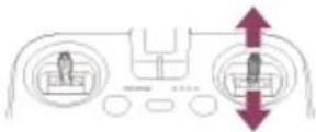 |
| Moving the aircraft left and right | Tilt the right stick left and right. 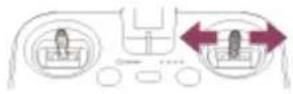 | Tilt the right stick left and right.  |
| Turning the aircraft left and right | Tilt the left stick left and right.  | Tilt the left stick left and right.  |
Hint
In the dual operation mode, you can select the operating mode of the gimbal with the sub controller.
Related Topic
• Parts and controls (Remote controller)
Features of the "Airpeak Flight" App
- Controlling the aircraft with two remote controllers (dual operation mode)
- Adjusting the sensitivity of the control sticks
5-027-737-11(1) Copyright 2021 Sony Group Corporation
Adjusting the sensitivity of the control sticks
You can adjust the sensitivity of the control sticks on the remote controller near the central position.
1 Tap [Start flight] on the "Airpeak Flight" App Home page.
The flight screen will be displayed.
2 Tap (Settings) in the top right of the screen.
3 Tap [Remote controller] in the displayed setting menu.
4 Tap [Sticks].
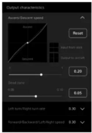
5 Set the values for [Output characteristics].
You can set the amount of movement along each axis ([Ascent/Descent speed]/[Left turn/Right turn rate]/[Forward/Backward/Left/Right speed]) with respect to the input from the control sticks.
The closer the value is to 1.00, the less sensitive the sticks will be. The closer the value is to -1.00, the more sensitive the sticks will be.
To prevent the sticks from reacting when you are not touching them, you can set the range within which the sticks do not react in [Dead zone].
Hint
- When you operate the control sticks, the white circle on the chart moves so that you can check the sensitivity level.
Related Topic
• Parts and controls (Remote controller)
Features of the "Airpeak Flight" App
- Selecting the operating mode of the control sticks
• Calibrating the remote controller
Changing the functions assigned to the custom buttons, lever, or dial on the remote controller
You can change the functions assigned to the custom buttons, control lever, or control dial on the remote controller.
1 Tap [Start flight] on the "Airpeak Flight" App Home page.
The flight screen will be displayed.
2 Tap (Settings) in the top right of the screen.
3 Tap [Remote controller] in the displayed setting menu.
4 Tap [Buttons/Controls].
5 Select the function that you want to assign to one of the custom buttons, the control lever, or the control dial.
- Custom buttons: Tap [Single press] or [Double press], and then select the function to be assigned in the menu for the button.
- Control lever/Control dial: Tap [Standard], and then select a function to be assigned when operating the control lever or control dial only. If you tap [Combination], you can select a function to be assigned when operating the control lever while pressing any of the custom buttons.
Hint
- You can assign different functions for each operation mode (single/dual) of the remote controller.
- When the remote controller is connected to the aircraft, the settings for the operation mode of the connected remote controller are displayed. When the remote controller is not connected to the aircraft, the settings for the single operation mode are displayed.
Related Topic
• Parts and controls (Remote controller)
Features of the "Airpeak Flight" App
- Controlling the aircraft with two remote controllers (dual operation mode)
Configuring the gimbal settings
You can configure settings related to the gimbal's movement.
1 Tap [Start flight] on the "Airpeak Flight" App Home page.
The flight screen will be displayed.
2 Tap (Settings) in the top right of the screen.
3 Tap [Gimbal] in the displayed setting menu.
4 Tap [Main control].
5 Set the following items.
• [Gimbal control mode]:
— [Lock]: The camera orientation (shooting direction) will remain the same even if the aircraft turns.
— [Follow]: The camera orientation (shooting direction) follows the panning (left/right) movement of the aircraft.
• Maximum speed (Pan/Tilt/Roll): You can set the maximum speed of movement along each axis.
- Smoothness (Pan/Tilt/Roll): You can set the smoothness of movement along each axis.
- EXPO (Pan/Tilt): You can set the amount of movement along each axis with respect to the input from the control sticks on the remote controller. To prevent the sticks from reacting when you are not touching them, you can set the range within which the sticks do not react in [Deadzone].
Related Topic
• Parts and controls (Remote controller)
• Parts and controls (Gimbal (sold separately))
Features of the "Airpeak Flight" App
- Adjusting the sensitivity of the control sticks
Checking settings before flights
Checking error messages in the flight screen
Error messages can be checked by accessing the flight screen from the "Airpeak Flight" App Home page.
Tap [Start flight] on the "Airpeak Flight" App Home page.1.
- Confirm that no error messages are displayed on the flight screen.
Confirm that no warnings, cautions, or dialogs are displayed.
Checking settings and status
Settings and status can be checked from the setting menu on the flight screen.
Tap [Start flight] on the "Airpeak Flight" App Home page.1.
- Tap (Settings) in the top right of the screen.
The setting menu will be displayed. Check the status of these items in the [Aircraft] and Remote controller] categories.
- Aircraft status
- Flight mode: [Aircraft] - [Flight mode]
- Maximum flight altitude: [Aircraft] - [Safety functions] - [Maximum altitude]
- Wireless performance: [Aircraft] – [Sensors/Radio]
• Remote controller status
- Remote controller operation mode: [Remote controller] - [Connection]
- Remote controller battery: [Remote controller] - [Details] - [Battery details]
- Battery pack status
- Aircraft battery packs: [Aircraft] - [Batteries]
- Aircraft battery pack temperature: [Aircraft] - [Batteries]
Operator's responsibilities
Before flights, read the Startup Guide and this Help Guide carefully to understand all safety features, warnings, and operations.
This product is intended for skilled persons who understand the maneuvering of the aircraft, relevant laws and regulations, and the dangers of exposed rotor blades.
- Operators should not fly the aircraft when they cannot recognize risks including, but not limited to, when under the influence of any mind altering substances (e.g. alcohol, etc.).
Although the aircraft features advanced technologies, careful decision-making by the operator is still necessary during flight. Flight assistance functions such as automated flight are designed to support the operator and are not intended as substitutes for the operator. The performance of the stereo cameras and other sensors may be affected by environmental factors such as the surrounding light, surface texture of obstacles, etc. Operators must be well-trained and aware of emergency measures in the event of an accident. - When flying the aircraft for videography/photography, respect the privacy of others and comply with state and local privacy laws and regulations as well as the reasonable expectation of privacy of the shooting location.
- Do not use this product for any illegal or improper purposes.
- Do not use this product for abuse, harassment, stalking, intimidation, or infringement upon the legal rights of others such as privacy or publicity rights.
- Do not allow the aircraft to trespass on the private property of others.
Unless permitted by separate prior written agreement between you and Sony, Airpeak is not for military use, including but not limited to the following: development of arms or munitions (including manufacturing, installation, and inspection), transportation of explosives or chemical or biological weapons and other harmful items, or activities such as intelligence, surveillance, and reconnaissance. Additionally, the aforementioned shall also apply to civilians and private citizens and entities, except with regard to surveillance, which is unauthorized only if such use is illegal and otherwise prohibited. - If any of the external devices installed on the aircraft falls off, it may cause injury or damage to buildings, people, or animals.
- Do not fly an aircraft that is in poor condition or has been damaged due to a crash or collision.
Flight environment
- Avoid obstacles such as large trees and power lines.
- Do not fly over people or near large crowds of people, unless you have received a waiver or your aircraft has a declaration of compliance to conduct such operations under applicable federal regulations.
- Do not fly at altitudes higher than 122 m (400 feet) above ground level (AGL) or, if higher than 122 m (400 feet) AGL, remain within 122 m (400 feet) of a structure.
- Fly in favorable weather conditions between -10^ (14 °F) and 40^ (104 °F).
- Do not fly in winds exceeding 20 m (66 feet)/s.
- Do not fly in rain, snow, or heavy fog, or during weather visibility that is less than 4.8 km (3 miles) from a control station.
- Do not use the aircraft during a natural or human-caused disaster that may impact flight performance or distract the remote pilot, such as a fire, explosion, flood, tidal wave, avalanche, landslide, earthquake, dust, sandstorm, or other similar circumstances.
- Fly outdoors. In buildings, the aircraft sensor system may be affected by interference, and accuracy of compass and GNSS (Global Navigation Satellite System) features may be impaired.
-
Do not fly low over water, ice, or snow surfaces. Flying too close to water, ice, or snow surfaces may cause a malfunction to the aircraft sensor system.
The Vision Positioning may not work properly in the following environments or under the following conditions: -
Areas where transparent objects such as water or glass are present, or where highly reflective objects such as mirrors are present
- When no objects that show clear surface patterns are present within an altitude of 20m (66 feet) or more and a circumference of 20m (66 feet)
- Areas where regular patterns are continuously present
- Areas exposed to strong light or areas where there are objects that emit light
— Areas where the illumination changes rapidly - Areas with illuminance equivalent to 100 lux or darker
— When the stereo camera lenses are dirty or when the stereo camera view is obstructed
— When the aircraft is flying low at a high speed or the aircraft is surrounded by objects at a short distance
— When the obstacle is small - When the surroundings or obstacles are moving
-
When there are objects in the blind spots of the stereo cameras and other sensors
— When the stereo cameras and other sensors are not calibrated properly -
The lateral performance of the Vision Positioning is reduced when the landing gear is up.
-
The flight assistance provided by the Vision Positioning and other sensors only supports the operator and does not guarantee the perfect safety of the flight. Always be cautious when flying the aircraft.
Note the following precautions during takeoff and landing and during flights: -
Keep people other than the flight operators away from the aircraft. Unexpected events such as gusts against the aircraft may cause injury.
— Take off and land on flat ground.
— Consider using a landing pad for takeoff and landing. In sandy environments, the aircraft may be damaged by wind-borne sand.
- Flight direction and positioning accuracy may be affected by degradation of wireless transmission quality and operating problems near airspace susceptible to magnetic or radio interference, such as near high-voltage power lines, large-scale power transmission stations, cell towers, and broadcast towers. Do not fly near this airspace, because you may lose control of the aircraft if the interference is too strong.
- Before flights, make sure that flying is legally permitted in the airspace where you plan to fly.
- Do not fly when visibility is poor, such as when there is heavy fog, and when you cannot see the aircraft with your own eyes. Only operate before sunrise, after sunset if you comply with federal regulations to do so and determine such an operation can be performed safely.
- Do not fly the aircraft from a moving vehicle unless you comply with federal regulations to do so and determine such an operation can be performed safely.
- To avoid affecting the service life of the motors, do not launch or land the aircraft in sandy or dusty areas.
- Do not load anything onto the aircraft other than the camera and other accessories as stated in the product information documents or as recommended by Sony.
- Comply with all laws, regulations or ordinances and obtain any required approval. Operators are responsible for complying with all applicable laws, regulations or ordinances while using the aircraft and remote controller.
- Do not fly in the No-fly zones. Contact the local aviation authorities for the latest No-fly zone list and comply with applicable laws, regulations or ordinances.
- Flight altitude restrictions may vary by jurisdiction. Do not fly above the maximum altitude stipulated by laws and regulations.
- Avoid flying in airspaces where rescue operations are underway.
5-027-737-11(1) Copyright 2021 Sony Group Corporation
SONY
Help Guide
Airpeak S1
ARS-S1
Airspace flight-restricted functions
This product is equipped with functions that provide information on flight-restricted airspace to support safe flight. If any of the following three airspace flight-restricted functions is enabled, warnings may be displayed in the “Airpeak Flight” App or some functions of the aircraft may be restricted, based on airspace information.
User-specified zones
The flight radius and altitude from the take-off position can be designated as a user-specified zone.
UTM-regulated zones
A UTM ^(*1) -regulated zone refers to flight-restricted airspace in accordance with the regulations of each country or region and user attributes.
To support safe flight, this product displays airspace information provided by AirMap, Inc., or such other third party UTM service provider named by Sony. When you fly the aircraft, be sure to make flight decisions based on the latest and official information.
It is important that you update the airspace database system saved in the aircraft and the "Airpeak Flight" App on a regular basis, especially before flying in a new location.
*1 UTM: Unmanned aircraft system Traffic Management
Geofence zones
You can create geofences with the "Airpeak Base" App and fly the aircraft only within the geofence zones.
About flight-restricted airspaces
• Flight-restricted airspaces are as follows.
- Outside user-specified zones
- Within UTM-regulated zones
- Outside geofence zones
- The aircraft cannot take off within a flight-restricted airspace. In addition, the control stick operations of the remote controller and some functions of the "Airpeak Flight" App are disabled.
- If the aircraft approaches a flight-restricted airspace, warnings will be displayed on the flight screen in the "Airpeak Flight" App and the aircraft will automatically decelerate or stop as needed.
Airspace information displayed in the "Airpeak Flight" App

1. Geofence zones
Geofences created in the "Airpeak Base" App are displayed.
Hint
- You can toggle the airspace flight-restricted functions on and off in the setting menu of the "Airpeak Flight" App (Settings) - [Aircraft] - [Safety functions]).
It is the remote pilot/operator's responsibility to always operate in accordance with the regulations of each country or region and user attributes. - You can update the airspace database system in the setting menu of the "Airpeak Flight" App (Settings) – [General] – [Maintenance]).
Related Topic
- Features of the "Airpeak Flight" App
- Setting the flight area for a project
- Setting geofences
5-027-737-11(1) Copyright 2021 Sony Group Corporation
Preflight checks
- Confirm that the aircraft and remote controller batteries are fully charged.
- Confirm that both battery packs are loaded in the aircraft.
- Use only genuine Sony parts or parts recommended by Sony, and confirm that all parts are free of damage and defects.
- Before loading battery packs, confirm that there is no moisture or foreign objects on battery pack terminals, terminals in the aircraft battery slots, on battery pack surfaces, or in the battery slots.
- Confirm that the propellers are free of damage and securely attached.
- If the propeller attachment point does not move smoothly, the propeller may fall off during flight and pose a risk of crash. Contact Sony Customer Support.
- Calibrate the aircraft compass by following the instructions displayed in the "Airpeak Flight" App.
- Before turning on the aircraft, confirm that there are no objects near the propellers that may come into contact with them.
- Confirm that the screws securing the damping plate to the aircraft are tight. Loose screws pose a risk of the gimbal and camera in it falling off during flights. As a preflight check item, always confirm that the screws are securely tightened.
- Confirm that aircraft motors are free of problems and work correctly.
- Confirm that the aircraft's stereo cameras, infrared range sensors, and FPV gimbal camera are free of dirt and debris.
- Confirm that there are no problems with gimbal operation.
- Calibrate the compass, IMU (Inertial Measurement Unit) and stereo cameras when prompted to do so in the “Airpeak Flight” App.
- Do not calibrate the compass in areas subject to strong magnetic interference, such as multi-storey parking facilities or underground steel-reinforced structures.
- Do not calibrate the aircraft's stereo cameras in a dark place or a place that is backlit by the sun or other light sources.
- Do not place ferromagnets near the product during calibration.
- Confirm that the number of GNSS (Global Navigation Satellite System) satellites is six or more in the “Airpeak Flight” App.
- Make sure that you fully understand the flight mode that you have selected, as well as the safety functions and warnings.
- Make sure that the “Airpeak Flight” App is working properly to assist you in controlling the aircraft. Sony may not be able to provide after-sales services or take responsibility under certain circumstances, such as when flight data recorded by the “Airpeak Flight” App is not present or the aircraft is lost.
- When you fly the aircraft with an external device loaded, check the following items before flight.
— Test the hovering performance of the aircraft prior to each flight.
- Confirm that the total takeoff weight does not exceed normal specifications.
— Confirm that there is no strong mechanical vibration in the aircraft, electromagnetic interference, or malfunction of the stereo cameras or infrared range sensors.
- Check the version numbers of the "Airpeak Flight" App and system software of the aircraft and remote controller to confirm that they are up to date.
Related Topic
Features of the "Airpeak Flight" App
- Charging the batteries
- Loading battery packs in the aircraft
- Attaching the damping plate to the aircraft
- Attaching the propellers
5-027-737-11(1) Copyright 2021 Sony Group Corporation
Precautions during flights
- Always operate the aircraft within the visual line of sight of the operator or a visual observer, unless you have received a waiver from the FAA to conduct an operation beyond visual line of sight.
- Keep away from the spinning propellers and motors in use.
- Propellers in motion are dangerous and should never be touched with your hands, rods or sticks, or by any other means.
- Do not touch the landing gear while the aircraft is in use. This may damage the aircraft or cause injury.
- Be careful not to cover aircraft or remote controller antennas by mistake. This may affect wireless transmission.
- Be careful not to cover the GNSS (Global Navigation Satellite System) antenna part of the aircraft by mistake. This may affect the attitude control of the aircraft.
- When the aircraft descends to a certain altitude from the ground, the landing protection function is activated to check if the terrain below is suitable for landing. If no problem is detected, the landing gear will be automatically lowered. However, the stereo cameras may not work properly or the ground surface may not be recognized under certain circumstances, such as when there is not enough light or there is an obstacle with an unclear surface pattern. Operate the aircraft with great caution.
- If the flight is unstable, land the aircraft immediately, and then check for any dirt on the sensors and calibrate them.
- Since the video transmission signal may be delayed or lost due to interference, the wireless transmission settings of the "Airpeak Flight" App ([Aircraft] — [Sensors/Radio]) should be changed carefully with a full understanding of the changes.
- After landing, first stop the motors, turn off the aircraft, and then turn off the remote controller. For safety, be sure to check that the motors have stopped rotating before turning off the aircraft and remote controller.
- Do not use mobile device features that may interfere with the operation of the aircraft, such as answering calls or replying to emails.
- To execute an emergency motor stop during a flight, tilt the left and right control sticks of the remote controller either inward and downward, or outward and downward at the same time. The aircraft will crash if the motors stop during a flight.
• To turn off the power, do the following:
— Aircraft: Press and hold the ⏻ (Power) button for at least 2 seconds.
- Remote controller: Press and hold the ⏻ (Power) button for at least 5 seconds.
• To force the power off, do the following:
— Aircraft: Remove the battery packs.
- Remote controller: Press and hold the ⏻ (Power) button for at least 10 seconds. If this does not turn off the remote controller, simultaneously press and hold the C2 (Custom 2) button and the ⏻ (Power) button for at least 10 seconds.
About the RTH (Return to Home) function
- The RTH (Return to Home) function may be affected by weather, the surrounding environment, or nearby magnetic fields.
- The aircraft cannot avoid obstacles if there is not enough surrounding light during RTH (Return to Home).
- Set the altitude for obstacle avoidance before performing RTH (Return to Home).
- RTH (Return to Home) does not work when there is an insufficient GNSS (Global Navigation Satellite System) signal (3 or fewer signal bars in the status bar of the “Airpeak Flight” App) or no signal is received from the GNSS (Global Navigation Satellite System).
About the remaining battery level
- If you are notified of low battery, land the aircraft immediately and safely.
- When the battery level drops below a certain level, a warning is displayed and the aircraft automatically starts descending to perform a forced landing. In order to steer the aircraft to an appropriate landing point while maintaining altitude, operate the remote controller to perform ascent while the aircraft is descending.
- If a battery level warning appears on the “Airpeak Flight” App screen, land the aircraft at the Home Point or a landing point immediately. If the battery packs run out of battery during flight, the aircraft may crash onto the ground, including private property, causing injury or damage to people or animals.
About the "Airpeak Flight" App
- Fully charge your mobile device before starting the "Airpeak Flight" App.
- When you operate the remote controller, be sure to start the "Airpeak Flight" App to assist in operating the aircraft.
- The “Airpeak Flight” App may use cellular data communication and incur usage charges according to the data plan provided by your carrier. For cellular data communication usage charges, contact your carrier.
- Read the safety tips, warning messages, and disclaimers displayed on the “Airpeak Flight” App screen carefully.
5-027-737-11(1) Copyright 2021 Sony Group Corporation
Setting the flight area for a project
The "Airpeak Base" App allows you to streamline the management of an entire flight as a project, from flight plans to flight logs. The data is stored on the cloud and can be displayed in the "Airpeak Flight" App when you actually fly the aircraft at the flight site.
1 Click on [Projects] on the "Airpeak Base" App Home page.
2 Click on [Create project].
3 Enter the project name, flight location, etc. into the dialog, and then click on [Create].
4 Click on the created project.
5 Click on [Check airspace].
The [Set flight location and flight date] screen will be displayed.
6 Click on [Flight date] on the right side of the screen and set the flight date.
7 Click on [Add flight area] at the bottom left of the screen, and then click on the map.
A polygon will appear on the map, indicating the flight area.
8 Edit the flight area.
Drag ○ (Point) on the edge of the flight area to form the desired shape.
9 Click on [Rules & compliance] on the right side of the screen and select the rules & compliance for displaying UTM (*1)-regulated zones. Then, click on [Set].
UTM-regulated zones based on the selected rules & compliance will be displayed on the map. If the flight area overlaps with a UTM-regulated zone, advisories will be displayed at the right side of the screen. Modify the flight area if necessary.
*1 UTM: Unmanned aircraft system Traffic Management
10 Click on [Save].
Related Topic
- Setting geofences
- Setting a flight path (mission)
Setting geofences
Flight restrictions such as flight area or maximum altitude can be defined as geofence zones for each project. Warnings are displayed on the flight screen in the "Airpeak Flight" App when the aircraft approaches the boundary of a geofence zone while in flight. You need to sign up for "Airpeak Plus" (paid plan) to use geofences.
1 Click on [Projects] on the "Airpeak Base" App Home page.
2 Click on the project for which you want to create geofences.
3 Click on [Add geofence] in the [Flight plans] tab, and then select [Create new geofence] from the menu.
The geofence editing screen will be displayed.
4 Click on [Add shape] at the bottom left of the screen and select [Circle] or [Polygon], and then click on the map.
A circle or polygon will appear on the map, indicating a geofence zone.
5 Edit the geofence.
- To edit a circle: To set the radius and maximum altitude, click within the geofence zone, and then set the values at the bottom of the screen. The same maximum altitude value applies to the entire zone within a circle.
- To edit a polygon: Drag ○ (Point) on the edge of the geofence zone to form the desired shape. To set the maximum altitude, click within the geofence zone, and then set the value at the bottom of the screen. The same value applies to the entire zone within a polygon.
6 Click on [Save] when you have completed editing. Enter the geofence name in the dialog, and then click on [Save].
Geofence editing screen
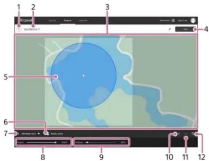

(Back)1.
2. Geofence name
Click to edit.
Map3.
4. [Save]
Click to save the geofence.
Geofence5.
6. (Delete point)
Click to delete the selected point.
7. [Add flight area]
Select [Circle] or [Polygon] and click on the map to place a geofence. The inside of the circle or polygon area is defined as a geofence zone.
8. [Radius]
Adjust the radius of the circle. This item does not appear when [Polygon] is selected.
9. [Altitude]
Adjust the maximum altitude. The aircraft will fly without exceeding this altitude.
10. + (Zoom in map)
Click to zoom in on the map.
11. — (Zoom out map)
Click to zoom out on the map.
12. (Select map layers)
Click to select information to overlay on the map.
Note
Note that an internet connection is required to sync geofence zone information between the "Airpeak Base" App and the "Airpeak Flight" App.
Related Topic
- Setting the flight area for a project
- Setting a flight path (mission)
Setting a flight path (mission)
Create a mission and then set a flight path.
1 Click on [Projects] on the "Airpeak Base" App Home page.
2 Click on the project for which you want to set a flight path.
3 Click on [Add mission] in the [Flight plans] tab, and then select [Create new mission] from the menu.
The [Create mission] dialog will be displayed.
4 Fill in the dialog, and then click on [Set].
• [Flight duration (30 fps)]: Set the flight duration.
• [Finish action]: Set a finish action for the aircraft.
The mission edit screen will be displayed.
5 Set a keyframe to the flight start position.

Make sure that the indicator (1) is at the "0" position of the elapsed time scale (2).
Drag (Aircraft) to the desired position on the map.2.
Click on ◇ (Set) (ββ.
The keyframe will be set to the flight start position.
6 Drag the indicator over the elapsed time scale to move to the next keyframe position.
7 Repeat procedures 2 and 3 of step 5 to set another keyframe.
The keyframes will automatically be connected by a natural curve to form a flight path. You can adjust the flight path later.
Repeat steps 6 and 7 to set more keyframes.
Click on [Check errors] when you have finished creating the flight path.
If errors are displayed, click on [Auto correct] to correct the errors that can be corrected automatically. If there are errors that cannot be corrected automatically, correct them manually.
Click on [Save].
Enter the mission name in the dialog, and then click on [Save].
Adjusting the flight path
Select a keyframe by clicking on it on the map.1.
Drag the keyframe or the handle to adjust the flight path.2.
Click on [Save] when you have completed the adjustment.3.
Adjusting the altitude of the flight path
- Click on [Altitude].
Changes in altitude are shown by a line on the graph.
- Select a keyframe on the line by clicking on it, and then drag the keyframe or the handle to adjust the altitude.
Click on [Save] when you have completed the adjustment.3.
Hint
- If you sign up for "Airpeak Plus," you can import or export a mission from : (Menu) on the mission edit screen. The following three formats can be selected.
— JSON: Select when using a mission with the "Airpeak Base" App
— ESP or KML: Select when using a mission with services from other companies
- When using missions with the “Airpeak Base” App, the camera orientation is displayed relative to space. The pan axis displays the north direction as 0°, the tilt axis displays the ground direction as 0°, and the roll axis displays the horizontal direction as 0°. When operating the gimbal with the “Airpeak Flight” App, the angle of the gimbal is displayed relative to the aircraft. The pan axis displays the forward direction of the aircraft as 0°, the tilt axis displays the horizontal direction of the aircraft as 0°, and the roll axis displays the horizontal direction of the aircraft as 0°.
Related Topic
- Setting the flight area for a project
- Setting geofences
- Flying the aircraft along a set path (automated flight)
Viewing flight logs
The "Airpeak Base" App allows you to check flight logs uploaded to the cloud from the "Airpeak Flight" App.
1 Click on [Logbook] on the "Airpeak Base" App Home page.
2 Click on the desired flight log in the flight log list.
The flight log screen will be displayed.
Flight log screen
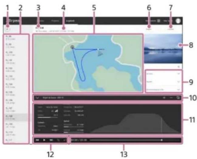

(Back)1.
- Flight log list
Click to display the flight log screen.
Flight log name3.
Flight log information (Flight location/flight date and time)4.
- Map
The flight path is indicated as a line. The icons on the map represent the following information.
• (Home Point)
• (Start or end location of video recording)
• O (Photographed location)
• (Aircraft position)
- [Export]
Click to save the flight log as a ALOG, ESP, or JSON file.
• ULOG: Format for reimporting as a flight log to the "Airpeak Base" App
- ESP: Format for checking the flight path using services from other companies
- JSON: Format for importing as a mission into the "Airpeak Base" App
7. [Convert]
Click to convert the flight log to a mission.
Thumbnails of images from the FPV gimbal camera8.
9. Right panel
- Warnings: Click to display details.
• [Devices]: Click to display the list of devices used for the flight.
• [Project]: Click to display project information.
• [Meteorological info]: Click to display the meteorological info during the flight.
• [Description]: Click to edit.
10. Flight log details panel (Top)
• (Show) / ▼ Hide): Click to show/hide the flight log details panel.
• [Distance]: Click to display the flight distance recorded in the flight log.
• + (Zoom in map): Click to zoom in on the map.
- (Zoom out map): Click to zoom out on the map.
- (Select map layers): Click to select information to overlay on the map.
11. Flight log details panel (Bottom)
The aircraft's position, speed, etc. is displayed.
12. Timeline panel (Playback operation buttons)
Click to play back the flight log.
(Go to beginning)
• ▶ (Play) / pause)
(Go to end)
- (Turn on repeat playback) / ← turn off repeat playback)
• ×1 (Playback speed)
13. Timeline panel (Timeline display)
• Elapsed time/flight duration
• Timeline bar: Drag the slider to move the playback point.
Related Topic
- Creating a new mission using a flight log
SONY
Help Guide
Airpeak S1
ARS-S1
Creating a new mission using a flight log
Make use of flight logs to create new missions efficiently.
1 Click on [Logbook] on the "Airpeak Base" App Home page.
2 Click on the flight log that you want to reuse.
3 Click on [Convert] at the top right of the flight log screen.
4 In the dialog, select the project to which you want to add a new mission, and then click on [Convert].
The flight log will be saved as a new mission for the selected project.
Related Topic
• Viewing flight logs
- Flying the aircraft again along a previous flight path (automated flight)
5-027-737-11(1) Copyright 2021 Sony Group Corporation
SONY
Help Guide
Airpeak S1
ARS-S1
Turning the aircraft on/off

1 Press and hold the ⏻ (Power) button (☐) on the aircraft for at least 2 seconds.
The aircraft is turned on. After startup, the power status LED (2) stops flashing and remains on.
To turn off the power
Press and hold the ⏻ (Power) button (☐ on the aircraft for at least 2 seconds.
The aircraft is turned off, and the power status LED (2) on the aircraft turns off.
5-027-737-11(1) Copyright 2021 Sony Group Corporation
SONY
Help Guide
Airpeak S1
ARS-S1
Turning the remote controller on/off
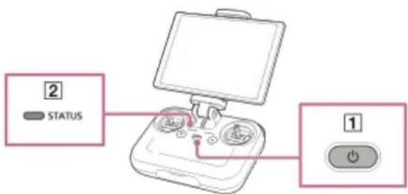
1 Press and hold the ⏻ (Power) button (☐) on the remote controller for at least 2 seconds.
The remote controller is turned on. After startup, the status LED (2) stops flashing and remains on.
To turn off the power
Press and hold the ⏻ (Power) button (☐) on the remote controller for at least 5 seconds.
The remote controller is turned off, and the status LED (2) on the remote controller turns off.
5-027-737-11(1) Copyright 2021 Sony Group Corporation
Relationship between the remote controller and the flight screen
The layout of the operating parts of the remote controller and the flight screen ("Airpeak Flight" App) is unified: the left side is for flight functions and the right side is for shooting functions.

- Flight operations
These parts are used for flight operations such as takeoff, landing, gimbal settings, etc.
- Camera operations
These parts are used for camera operations such as taking videos and photos, settings, etc.
Related Topic
• Parts for flight operations
• Parts for shooting operations
SONY
Help Guide
Airpeak S1
ARS-S1
Parts for flight operations
The parts used for flight operations are described below.
Remote controller
The parts of the remote controller used for flight operations are described below.

- Control sticks
Control the orientation and movement of the aircraft.
There are two stick operating modes: [Mode 2] (default setting) and [Mode 1].
- (Automated flight pause) button
Press to pause the aircraft's movement during automated flight, if necessary to ensure safety.
- Control lever
Tilts the gimbal (up/down).
- Flight mode switch
Selects the flight mode (1/2/3).
- C1 (Custom 1)/C2 (Custom 2)/C3 (Custom 3)/C4 (Custom 4) buttons
Assign the functions for operating the aircraft, camera, and gimbal to these buttons in the setting menu of the "Airpeak Flight" App.
Flight screen ("Airpeak Flight" App)
The items on the flight screen used for flight operations are shown below.

- (Back)
Tap to go back to the App Home page.
- Telemetry
(Flight mode indication): Indicates the current position of the flight mode switch on the remote controller and the current flight mode.
- Distance (Horizontal information indication): Indicates the horizontal speed of the aircraft and the distance from the take-off position.
(Vertical information indication): Indicates the vertical speed of the aircraft and the altitude relative to the take-off position. The Vision Positioning altitude is also displayed when the Vision Positioning function is enabled.
-
Radio reception information
-
[GNSS] (Indication of the number and signal strength of positioning satellites such as GNSS (Global Navigation Satellite System))
(Indication of the signal strength of the remote controller) -
Remaining battery level
(Indication of the remaining flight time and remaining battery of the aircraft): Indicates the remaining flight time until forced landing due to insufficient battery power. The remaining battery level of the aircraft is indicated as a numerical value and a bar. The red area shows the remaining amount set for [Aircraft] — [Batteries] — [Start forced landing [%]] in the setting menu, and the yellow area shows the remaining amount set for [Battery-life alert [%]]. The triangle mark indicates the minimum battery level required to return to the Home Point. When the battery level drops to the level indicated by the triangle mark, the aircraft starts to perform RTH (Return to Home).
-
Camera (Indication of the remaining battery of the camera)
• (Indication of the remaining battery of the mobile device) -
(Settings)
Tap to display the setting menu. Tap ✗ (Close) to hide the menu.
Side menu6.
Displays the current setting value inside each button. If your mobile device has a small screen, not all of the buttons are displayed. To display other buttons, swipe vertically on the side menu.
• [Display aircraft's battery details]
Displays the status of the aircraft battery packs.
• [Tilt smoothness]
Adjusts the smoothness of the gimbal's tilting (up/down) movement.
• [Pan smoothness]
Adjusts the smoothness of the gimbal's panning (left/right) movement.
• [Gimbal control mode]
Selects the gimbal control mode.
• [Auto control landing gear]
Toggles the automatic landing gear control function on and off with each tap.
• [Vision Positioning]
Toggles the Vision Positioning function on and off with each tap.
7. (FPV)
Tap to display the FPV view in a sub screen.
8. (RTH (Return to Home))
Tap to automatically return the aircraft to the Home Point.
9. / (Landing gear up/down)
Tap to raise or lower the landing gear.
10. (Obstacle brake)
Tap to toggle the obstacle brake on and off for all directions except downward.
You can enable/disable the brake for each direction in the setting menu of the "Airpeak Flight" App (Settings) - [Aircraft] - [Sensors/Radio] - [Obstacle brake]).
11. (Automated flight menu)
Tap to display the [Flight functions] menu.
12. (Auto take off)/ (Auto landing)/ (Automated flight start)/ (Automated flight pause)
Tap to perform takeoff and landing. The indication changes according to the flight status.
13. (Informational content switching)
Tap to change the amount of information displayed on the flight screen.
14. MAP (Map)
Tap to display the map view in a sub screen.
Related Topic
• Parts and controls (Remote controller)
- Setting the flight mode
- Selecting the operating mode of the control sticks
- Adjusting the sensitivity of the control sticks
- Changing the functions assigned to the custom buttons, lever, or dial on the remote controller
• Parts for shooting operations
Switching views on the flight screen
The following views are available on the flight screen of the "Airpeak Flight" App.
- Camera view: Displays the image from the camera in full-screen.
- FPV view: Displays the image from the FPV gimbal camera of the aircraft in the sub screen at the bottom left of the screen.
- Map view: Displays a map in the sub screen at the bottom right of the screen.
You can switch the views among the sub screens and the full screen.
1 Tap [Start flight] on the "Airpeak Flight" App Home page.
The flight screen will be displayed with the camera view in full-screen.
2 To display the FPV view, tap (FPV). To display the map view, tap (Map).
The FPV view will appear in the sub screen at the bottom left of the screen. The map view will appear in the sub screen at the bottom right of the screen.
3 Tap one of the sub screens.
The views in the sub screen and the full screen will switch. To hide the sub screen, tap (FPV) or (Map).
Related Topic
• Parts for flight operations
• Parts for shooting operations
Controlling the aircraft with the remote controller (manual flight)
There are two flight methods for this aircraft: manual flight, in which the aircraft is controlled with the remote controller, and automated flight, in which the aircraft automatically flies without user operation. This topic describes the operations for manual flight.
1 Turn on the aircraft and place it on a flat surface.
2 Tap [Start flight] on the "Airpeak Flight" App Home page.
The flight screen will be displayed.
3 Launch the aircraft.
Manual takeoff
- Tilt the left and right control sticks on the remote controller either inward and downward, or outward and downward at the same time.
The motors will start and the propellers start rotating.
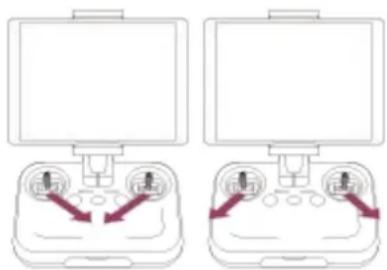
natural_image
Two identical diagrams showing a device with two ports and directional arrows, no text or symbols present.Operate the control sticks on the remote controller to make the aircraft ascend.2.
Automated takeoff
- On the flight screen in the "Airpeak Flight" App, tap 📁 (Auto take off) and follow the instructions on the screen. The motors will start and the propellers will start rotating. Then, the aircraft will take off.
The landing gear will rise when the aircraft ascends to a certain height above the take-off position.
4 Control the aircraft manually with the remote controller.
The left and right control sticks work as follows when [Stick operating mode] is set to [Mode 2] (default).
Left stick
- Tilt up/down: Ascend/descend.
- Tilt left/right: Turn left/right.
Right stick
- Tilt up/down: Fly forward/backward.
- Tilt left/right: Fly left/right.
5 Land the aircraft.
Manual landing
- Operate the control sticks on the remote controller to make the aircraft descend. The landing gear will lower when the aircraft descends to a certain height above the ground.
- Keep operating the control sticks until the aircraft lands and the motors stop. After the motors stop, release the control sticks to return them to the central position.
Automated landing
- On the flight screen in the "Airpeak Flight" App, tap ☐ (Auto landing) and follow the instructions on the screen. The landing gear will lower when the aircraft descends to a certain height above the ground, and then the aircraft will land and motors will stop.
Note
- Keep away from the spinning propellers and motors in use.
- Raise or lower the landing gear manually if you have set [Auto control landing gear] to off.
Related Topic
- Selecting the operating mode of the control sticks
- Adjusting the sensitivity of the control sticks
Operator's responsibilities
• Flight environment - Preflight checks
• Precautions during flights
• Parts for flight operations - Landing gear operation
- Executing an emergency motor stop
5-027-737-11(1) Copyright 2021 Sony Group Corporation
Flying the aircraft along a set path (automated flight)
You can automatically fly the aircraft according to a mission (flight path) created using the "Airpeak Base" App.
1 Create projects and missions based on your flight plan with the "Airpeak Base" App.
The projects and missions will be stored in the cloud.
2 Start the "Airpeak Flight" App.
Projects and missions created in the “Airpeak Base” App are automatically downloaded from the cloud to the “Airpeak Flight” App.
You can also download projects and missions manually by tapping the account icon and then [Sync with cloud] on the "Airpeak Flight" App Home page.
3 Tap (Project selection) on the "Airpeak Flight" App Home page.
The project selection screen will be displayed.
4 Tap the project that contains the desired mission.
5 Turn on the aircraft and place it on a flat surface.
6 Tap [Start flight] on the "Airpeak Flight" App Home page.
The flight screen will be displayed.
7 Tap (Automated flight menu).
8 In the [Flight functions] menu, tap [Mission Flight].
9 In the mission list, tap the mission according to which you want to fly the aircraft.
A map that shows the flight path of the selected mission will be displayed on the screen.
10 In the [Edit flight path] menu, check the flight path, edit it if necessary, and then tap [Next].
11 In the [Flight settings] menu, select the desired setting values, and then tap [Next].
A preflight check will be performed. If errors are detected, fix them.
12 Tap [Start flight].
The aircraft will start the automated flight. If there is some distance to the starting point of the flight path, the aircraft will fly automatically to the starting point (preparation flight). Make fine adjustments to the flight path or pause/stop the flight if necessary.
When the aircraft reaches the end point, it will hover or perform RTH (Return to Home) depending on the settings.
Pausing an automated flight
If you press the ⚠ (Automated flight pause) button on the remote controller during an automated flight, the automated flight will be paused and the aircraft will hover. Horizontal movement/turning/ascending/descending/stop operations can be performed while paused. To resume automated flight, tap ⚠ (Automated flight start) on the flight screen of the "Airpeak Flight" App.
Switching to a manual flight
Tap [Cancel] (1) on the flight screen of the "Airpeak Flight" App during the automated flight to stop the automated flight. The aircraft will hover.
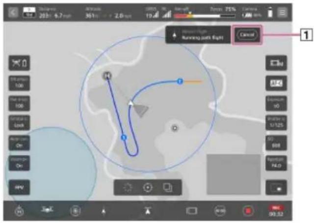
Adjusting the flight path manually
You can make fine adjustments to the flight path with the control sticks on the remote controller during an automated flight. The flight path will move in parallel in the direction in which the control stick is operated.
Related Topic
Features of the "Airpeak Flight" App
- Selecting the operating mode of the control sticks
- Adjusting the sensitivity of the control sticks
• Operator's responsibilities
• Flight environment
- Preflight checks
• Precautions during flights
- Setting a flight path (mission)
• Parts for flight operations
- Landing gear operation
• Executing an emergency motor stop
Flying the aircraft again along a previous flight path (automated flight)
By using a flight log stored in the cloud, you can automatically fly the aircraft along a previous flight path.
Preparation
See “Creating a new mission using a flight log” to convert the flight log that you want to reuse into a mission.
1 Start the "Airpeak Flight" App.
Projects and missions created in the "Airpeak Base" App are automatically downloaded from the cloud to the
"Airpeak Flight" App.
You can also download projects and missions manually by tapping the account icon and then [Sync with cloud] on the "Airpeak Flight" App Home page.
2 Tap ■ (Project selection) on the “Airpeak Flight” App Home page.
The project selection screen will be displayed.
3 Tap the project that contains the mission you created in advance.
Turn on the aircraft and place it on a flat surface.
5 Tap [Start flight] on the "Airpeak Flight" App Home page.
The flight screen will be displayed.
6 Tap (Automated flight menu).
In the [Flight functions] menu, tap [Mission Flight].
8 In the mission list, tap the mission that you created in advance.
A map that shows the flight path of the selected mission will be displayed on the screen.
9 In the [Edit flight path] menu, check the flight path, edit it if necessary, and then tap [Next].
In the [Flight settings] menu, select the desired setting values, and then tap [Next].
A preflight check will be performed. If errors are detected, fix them.
11 Tap [Start flight].
The aircraft will start the automated flight. If there is some distance to the starting point of the flight path, the aircraft will fly automatically to the starting point (preparation flight). Make fine adjustments to the flight path or pause/stop the flight if necessary.
When the aircraft reaches the end point, it will hover or perform RTH (Return to Home) depending on the settings.
Pausing an automated flight
If you press the ⚠ (Automated flight pause) button on the remote controller during an automated flight, the automated flight will be paused and the aircraft will hover. Horizontal movement/turning/ascending/descending/stop operations can be performed while paused. To resume automated flight, tap ⚠ (Automated flight start) on the flight screen of the "Airpeak Flight" App.
Switching to a manual flight
Tap [Cancel] (1) on the flight screen of the "Airpeak Flight" App during the automated flight to stop the automated flight. The aircraft will hover.

Adjusting the flight path manually
You can make fine adjustments to the flight path with the control sticks on the remote controller during an automated flight. The flight path will move in parallel in the direction in which the control stick is operated.
Related Topic
- Selecting the operating mode of the control sticks
- Adjusting the sensitivity of the control sticks
• Operator's responsibilities
• Flight environment - Preflight checks
• Precautions during flights
• Viewing flight logs - Creating a new mission using a flight log
• Parts for flight operations - Landing gear operation
• Executing an emergency motor stop
Returning the aircraft to the Home Point (RTH (Return to Home))
The aircraft can automatically return to the Home Point. This function is called RTH (Return to Home). The take-off position is automatically set as the Home Point.
On the flight screen in the "Airpeak Flight" App, tap 📋 (RTH (Return to Home)) and follow the instructions on the screen.
The aircraft will perform RTH (Return to Home).
Hint
- RTH (Return to Home) is automatically performed when the battery level of the aircraft is low or unrecoverable software errors are detected. The movement of the aircraft when there is poor communication between the aircraft and the remote controller can be set in the setting menu for the "Airpeak Flight" App (Settings) - [Aircraft] - [Safety functions]).
- If an obstacle is detected in front of the aircraft during RTH (Return to Home), the aircraft will ascend 3 meters vertically to avoid the obstacle.
Related Topic
• Parts for flight operations
5-027-737-11(1) Copyright 2021 Sony Group Corporation
SONY
Help Guide
Airpeak S1
ARS-S1
Landing gear operation
The landing gear can be raised or lowered automatically or manually.
At the time of purchase, [Auto control landing gear] is enabled and the landing gear is automatically raised or lowered according to the altitude of the aircraft. Raise or lower the landing gear manually when [Auto control landing gear] is set to off.
To raise or lower the landing gear manually
Tap 🚗 (Raise the landing gear) or 🚗 lower the landing gear) on the flight screen of the "Airpeak Flight" App and follow the instructions on the screen.
Related Topic
• Parts and controls (Aircraft)
• Parts for flight operations
5-027-737-11(1) Copyright 2021 Sony Group Corporation
Executing an emergency motor stop
You can stop the motors of the aircraft in urgent situations such as avoiding danger during a flight.

Tilt the left and right control sticks on the remote controller either inward and downward, or outward and downward at the same time.
The motors and propellers will stop. The aircraft will fall if the motors stop during a flight.
Hint
- You can deactivate the emergency motor stop function. On the flight screen of the "Airpeak Flight" App, tap (Settings) – [Aircraft] – [Safety functions] and turn off the [Execute emergency motor stop] switch.
Related Topic
• Parts for flight operations
5-027-737-11(1) Copyright 2021 Sony Group Corporation
Relationship between the remote controller and the flight screen
The layout of the operating parts of the remote controller and the flight screen ("Airpeak Flight" App) is unified: the left side is for flight functions and the right side is for shooting functions.
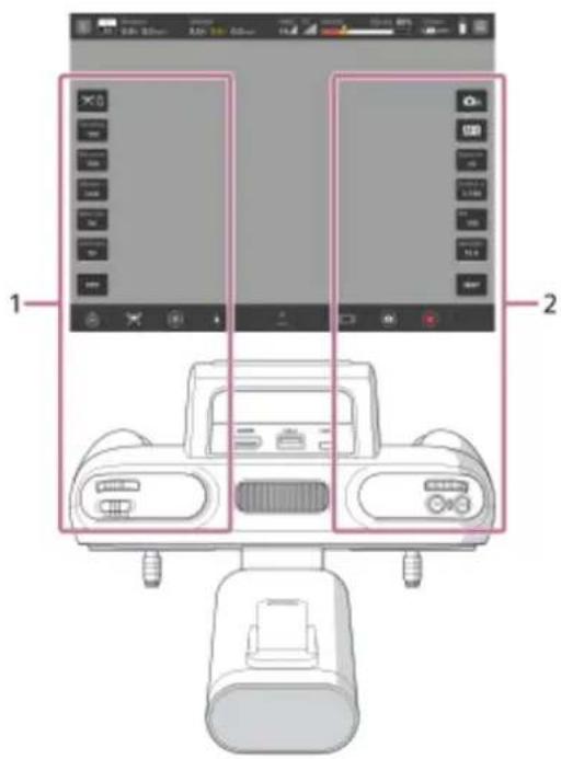
- Flight operations
These parts are used for flight operations such as takeoff, landing, gimbal settings, etc.
- Camera operations
These parts are used for camera operations such as taking videos and photos, settings, etc.
Related Topic
• Parts for flight operations
• Parts for shooting operations
SONY
Help Guide
Airpeak S1
ARS-S1
Parts for shooting operations
The parts used for shooting operations are described below.
Remote controller
The parts of the remote controller used for shooting operations are described below.
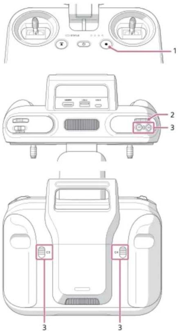
- (MOVIE) button
Press to start/stop video recording.
- Control dial
Turn to change the setting values of the camera.
- C1 (Custom 1)/C2 (Custom 2)/C3 (Custom 3)/C4 (Custom 4) buttons
Assign the functions for operating the aircraft, camera, and gimbal to these buttons in the setting menu of the "Airpeak Flight" App.
Flight screen (the "Airpeak Flight" App)
The items on the flight screen used for shooting operations are described below.

1. (Back)
Tap to go back to the App Home page.
2. Telemetry
(Flight mode indication): Indicates the current position of the flight mode switch on the remote controller and the current flight mode.
(Horizontal information indication): Indicates the horizontal speed of the aircraft and the distance from the take-off position.
(Amounts 0.0-0.0, 0.0-0.1) (Vertical information indication): Indicates the vertical speed of the aircraft and the altitude relative to the take-off position. The Vision Positioning altitude is also displayed when the Vision Positioning function is enabled.
3. Radio reception information
(Indication of the number and signal strength of positioning satellites such as GNSS (Global Navigation Satellite System))
(Indication of the signal strength of the remote controller)
4. Remaining battery level
(Indication of the remaining flight time and remaining battery of the aircraft): Indicates the remaining flight time until forced landing due to insufficient battery power. The remaining battery level of the aircraft is indicated as a numerical value and a bar. The red area shows the remaining amount set for [Aircraft] — [Batteries] — [Start forced landing [%]] in the setting menu, and the yellow area shows the remaining amount set for [Battery-life alert [%]]. The triangle mark indicates the minimum battery level required to return to the Home Point. When the battery level drops to the level indicated by the triangle mark, the aircraft starts to perform RTH (Return to Home).
(Indication of the remaining battery of the camera)
• (Indication of the remaining battery of the mobile device)
5. (Settings)
Tap to display the setting menu. Tap ✗ (Close) to hide the menu.
6. Side menu
Displays the current setting value inside each button. If your mobile device has a small screen, not all of the buttons are displayed. To display other buttons, swipe vertically on the side menu.
[Shoot mode]
Selects the shooting mode of the camera.
• [Focus mode]
Selects the focus mode of the camera.
• [Exposure comp.]
Normally, the exposure is set automatically (auto exposure). You can adjust the exposure based on the exposure value set via auto exposure. The entire image will become brighter if you set the exposure to a larger value.
[Shutter speed]
Adjusts the shutter speed of the camera.
• [ISO]
Adjusts the ISO number (recommended exposure index) of the camera. A larger number increases the sensitivity as well as noise.
• [Aperture]
Adjusts the aperture value (F-value) of the camera. The subject and its foreground and background are all in focus with a larger F-value.
- MAP (Map)
Tap to display the map view in a sub screen.
- REC / (Elapsed recording time)
Displays the elapsed recording time during video recording.
- (Movie recording)
Tap to start/stop recording a video.
- (Still image shooting)/ (AF-ON)
(Still image shooting): Tap to shoot a still image.
(AF-ON): Tap to enable the auto focus during video recording.
- (Information amount switching)
Tap to change the amount of information (show/hide item names) displayed on the flight screen.
- FPV (FPV)
Tap to display the FPV view in a sub screen.
Related Topic
• Parts and controls (Remote controller)
- Changing the functions assigned to the custom buttons, lever, or dial on the remote controller
• Parts for flight operations
SONY
Help Guide
Airpeak S1
ARS-S1
Checking the status of the devices
When you use devices such as the aircraft and the remote controller for flight, device information is automatically collected via the "Airpeak Flight" App and displayed on the [Devices] screen of the "Airpeak Base" App. You can check the usage status, maintenance information, etc. of each device on this screen.
1 Click on [Devices] on the "Airpeak Base" App Home page.
2 On the [Devices] screen, click on the device whose information you want to check.
3 Check the usage status, maintenance information, etc.
5-027-737-11(1) Copyright 2021 Sony Group Corporation
Calibrating the sensors of the aircraft
Adjust any misalignment of the sensors mounted on the aircraft so that the aircraft can fly in a stable manner. Each sensor functions as follows.
- Compass: Detects the earth's magnetism and measures the direction so that the aircraft can be kept in the correct orientation.
- IMU (*1): Measures the inclination and acceleration/deceleration of the aircraft.
- Stereo camera: Multiple cameras capture objects three-dimensionally and assess the distances to the objects and their moving speeds.
*1 IMU: Inertial Measurement Unit
1 Tap [Start flight] on the "Airpeak Flight" App Home page.
The flight screen will be displayed.
2 Tap (Settings) in the top right of the screen.
3 Tap [Aircraft] in the displayed setting menu.
4 Tap [Sensors/Radio].
5 Tap [Compass], [IMU], or [Stereo camera].
6 Follow the instructions on the screen to complete the calibration.
Related Topic
• Calibrating the remote controller
Calibrating the remote controller
Calibrate the remote controller if you have not used it for a long period of time or if the control sticks and control lever on the remote controller are misaligned.
1 Tap [Start flight] on the "Airpeak Flight" App Home page.
The flight screen will be displayed.
2 Tap (Settings) in the top right of the screen.
3 Tap [Remote controller] in the displayed setting menu.
4 Tap [Details].
5 Tap [Start] for [Calibrate remote controller].
6 Follow the instructions on the screen to complete the calibration.
Related Topic
- Adjusting the sensitivity of the control sticks
• Calibrating the sensors of the aircraft
5-027-737-11(1) Copyright 2021 Sony Group Corporation
Updating the system software
Update the systems software of the aircraft and remote controller. To update the system software, connect the mobile device attached to the remote controller to the internet and perform the following operations with the aircraft and remote controller connected.
1 Tap [Start flight] on the "Airpeak Flight" App Home page.
The flight screen will be displayed.
2 Tap (Settings) in the top right of the screen.
3 Tap [General] in the displayed setting menu.
4 Tap [Maintenance].
5 Tap [Update] for [System software].
The update wizard will start.
6 Follow the instructions on the screen to complete the update.
Hint
- If a system software update is available, a notification will be displayed on the "Airpeak Flight" App Home page.
Related Topic
Features of the "Airpeak Flight" App
Airpeak S1
ARS-S1
Before disposing of this product
Before disposing of the Airpeak, including the remote controller and/or battery charger, visit https://www.sony.com/ecotrade. Recycling information for all products, including batteries can be found.
5-027-737-11(1) Copyright 2021 Sony Group Corporation
General Information
Aircraft/Gimbal
Using the product
- Comply with all applicable laws, regulations and ordinances, including the Federal Aviation Administration's regulations in 14 C.F.R. Part 107, while using the aircraft and remote controller.
- For safety, do not change or modify aircraft components. When installing external devices, be aware of the aircraft weight after installation. Do not install external devices that exceed the maximum payload. As external devices, use only genuine Sony devices or devices recommended by Sony, and install in the correct position as described in the instruction manual. Devices that shift the aircraft center of gravity pose a risk of crashes.
Included AC power cord
Use only the included or Sony recommended AC power cord.
AC adapters
Use only the included or Sony recommended AC adapters.
Carrying components
- When carrying the aircraft, hold it securely by the frame arms. If you do not hold it securely by the frame arms, you may drop and damage the aircraft or hurt yourself.
- When carrying the remote controller, hold it by the handle bar. Do not apply excessive force to the handle bar, control sticks, or mobile device holder, which may damage these parts.
- Be careful not to drop the aircraft or remote controller when carrying these components. Drops may cause damage or injury.
Installing external devices
The aircraft USB port can supply up to 500 mA of current. If overcurrent conditions exceeding 500 mA occur while an external device is installed, it may affect flight performance.
Maintenance and storage
- The recommended ambient temperature range for storage is 18 °C (64 °F) to 30 °C (86 °F).
- Thoroughly wipe off any water that has adhered to the aircraft before storing it.
- Do not use the product if you notice any damage or deterioration to the propellers or propeller attachment points of the aircraft.
- Gently wipe off any dirt or dust on the aircraft, remote controller, battery charger, or battery packs with a soft, dry cloth.
- Do not use volatile substances such as alcohol or paint thinner as they may damage the parts and cause deterioration.
- This product contains consumable/wear parts such as rubber parts, motors, etc.
- To use the product safely, regular inspections are required in addition to the preflight checks mentioned in this Help Guide.
- It is recommended that you perform regular inspections after 250 flights or 50 hours of total flight, although it depends on the usage conditions and environment.
- Items subject to regular inspection include the following: movement of the moving parts such as motors, condition of the consumable/wear parts, damage or deformation in each part of the cabinet, and basic functions such as the sensors and communication function.
- For detailed information, contact the place of purchase or Sony Customer Support.
Remote Controller
- This product is designed for use only in the U.S.A. Operation is not guaranteed when used in other countries or regions.
- Do not connect the AC adapter to an electronic transformer (travel converter). This may cause heat generation or product failure.
- The wireless transmission function of the product is designed for use only in the U.S.A. Use in other countries or regions may be punishable by law.
Caution when carrying the unit
Carry the unit by the handle bar. The handle bar, control sticks, and mobile device holder may break if excessive force is applied to these parts.
Battery Charger
- This product is designed for use only in the U.S.A. Operation is not guaranteed when used in other countries or regions.
About charging
- Two battery packs can be inserted into the unit, but they cannot be charged at the same time. After one battery pack is fully charged, the other will start charging.
- It may take about 20 seconds to start charging. Wait until the battery level LEDs on the battery pack blink.
- If the battery temperature is too high or low, charging will not start due to the protection function. When the battery temperature enters the chargeable range in a room-temperature environment, charging will start automatically.
- If charging does not start indefinitely, remove the battery pack from the unit, unplug the AC adapter power cord from the wall outlet, and then reconnect it. If charging still does not start, refer to our support website for a solution. https://www.sony.com/electronics/support
Caution when carrying the unit
When carrying the unit, take care not to drop it. If the unit is dropped, this may cause damage to the unit or injuries.
Battery Pack
Charging the battery pack
- Before using the battery pack, be sure to charge it with a Sony dedicated battery charger or a Sony device with a battery-charging function (a device capable of charging this battery pack). To charge the battery efficiently, fully charge it in an ambient temperature of 5^ - 40^ ( 41^ - 104^ ). See the instruction manual of the device that is to perform charging for details of the charging method and the charging time.
- Do not touch the battery pack while charging is in process.
- Do not charge the battery pack for longer than the specified charging time.
Effective use of the battery pack
Battery pack performance decreases in low-temperature surroundings.
How to store the battery pack
- Do not short-circuit or allow metal objects to come into contact with the battery terminals when carrying or storing a battery pack.
- Do not store the battery pack for long periods in a completely discharged state.
- When storing the battery pack for long periods, first remove it from the aircraft or battery charger and then store it in a cool place.
Battery life
- The battery life is limited. The battery capacity will decrease little by little with repeated use and over time. If the remaining battery time is considerably shortened, the battery pack is reaching the end of its life. Replace with a new battery pack.
- The battery life varies according to the storage, operating conditions and environment.
Related Topic
• Parts and controls (Aircraft)
• Parts and controls (Remote controller)
• Turning the aircraft on/off
• Turning the remote controller on/off
5-027-737-11(1) Copyright 2021 Sony Group Corporation
SONY
Help Guide
Airpeak S1
ARS-S1
Troubleshooting
If you experience trouble with the product, try the following solutions.
1 Cycle the power.
Remote controller: Turn off the power and then turn it back on after about 1 minute.
Aircraft: Turn off the power and remove both battery packs. After about 1 minute, reinsert the battery packs and turn the power back on.
2 Check the additional information on our Customer Support Website.
https://www.sony.com/electronics/support
Related Topic
• Turning the aircraft on/off
• Turning the remote controller on/off
5-027-737-11(1) Copyright 2021 Sony Group Corporation
Trademarks and copyrights
• Wi-Fi is registered trademark of Wi-Fi Alliance.
The Bluetooth ^® word mark and logos are registered trademarks owned by Bluetooth SIG, Inc. and any use of such marks by Sony Group Corporation and its subsidiaries is under license.
- The terms HDMI and HDMI High-Definition Multimedia Interface, and the HDMI Logo are trademarks or registered trademarks of HDMI Licensing Administrator, Inc. in the United States and other countries.
- USB Type-C® and USB-C® are trademarks of USB Implementers Forum.
- Apple ^ , iPad ^ and iPhone ^ are either trademarks or registered trademarks of Apple Inc., registered in the U.S. and other countries.
- Use of the Made for Apple badge means that an accessory has been designed to connect specifically to the Apple product(s) identified in the badge and has been certified by the developer to meet Apple performance standards. Apple is not responsible for the operation of this device or its compliance with safety and regulatory standards.
- Please note that use of an accessory with an Apple product may affect wireless performance.
System and/or product names mentioned in this document are, in general, registered trademarks or trademarks of their respective developers and the “TM” and “®” marks are omitted in the text. Furthermore, any copyrights not explicitly mentioned in this document are the property of their respective owners.
Made for
iPhone | iPad
HDMI
5-027-737-11(1) Copyright 2021 Sony Group Corporation

- Before first use
- About this product
- Package contents
- Guide to parts and controls
- Using the dedicated apps
- Using the "Airpeak Base" App
- Using the "Airpeak Flight" App
- Getting ready
- Preparing the batteries
- Preparing the aircraft
- Preparing the gimbal and a camera
- Preparing the remote controller
- Linking the aircraft and remote controller
- Configuring various settings before flights
- Flight precautions
- Making a flight plan
- Shooting
- Maintaining the devices
- Precautions
- Introduction
- Highlights
- Agile flying performance and control that unleashes the potential of cameras
- Expands possibilities in aerial photography
- Streamlines workflows with automation
- System configuration
- Aircraft
- Remote controller/dedicated mobile app "Airpeak Flight"
- Dedicated web app "Airpeak Base"
- Note
- SONY
- Help Guide
- Supported mobile devices
- Supported cameras and lenses
- Gimbal set (sold separately)
- Parts and controls (Aircraft)
- LINK button
- Power status LED
- Battery level LEDs
- Flight status LEDs (Rear LEDs)
- Related Topic
- Detection range of the infrared range sensors and stereo cameras
- Detection range of the infrared range sensors
- Side view (The left side is the front of the aircraft.)
- Rear view
- Detection range of the stereo cameras
- Front view
- Top view
- Parts and controls (Remote controller)
- Status LED
- (Automated flight pause) button
- (MOVIE) button
- Battery level LEDs
- Control sticks
- Lever heads
- Mobile device holder
- USB port (USB-A)
- Handle bar
- Control lever
- Flight mode switch
- Air vent
- C1 (Custom 1) button
- C2 (Custom 2) button
- Control dial
- C3 (Custom 3) button
- Air inlet
- C4 (Custom 4) button
- Parts and controls (Gimbal (sold separately))
- Features of the "Airpeak Base" App
- The "Airpeak Base" App Home page
- [Devices]
- [Projects]
- [Logbook]
- Installing the "Airpeak Flight" App
- Signing in to the "Airpeak Flight" App
- Start the "Airpeak Flight" App.
- Follow the on-screen instructions to create a Sony account.
- Sign in to the "Airpeak Flight" App.
- Features of the "Airpeak Flight" App
- Screen flow of the "Airpeak Flight" App
- A App Home page
- B Flight screen
- C Setting menu
- App Home page
- Charging the batteries
- Charging the aircraft battery packs
- To check the battery level
- Charging the built-in remote controller battery
- If you cannot charge the aircraft battery pack
- Loading battery packs in the aircraft
- Load the battery packs in the aircraft.
- Confirm that the battery packs are loaded correctly.
- Hint
- Connecting cables to the aircraft
- Front of aircraft
- Rear of aircraft
- Attaching the damping plate to the aircraft
- Attach the damping plate to the aircraft.
- Insert the plugs at the other ends of the cables connected to the aircraft in the corresponding quick-release ports.
- Attaching landing gear
- To remove the landing gear
- Attaching the propellers
- Make sure the aircraft is off.
- Check the propeller hub.
- Attach the propellers (CW) (1) to the motors with silver hubs.
- Attach the propellers (CCW) (Bto the motors with black hubs.
- To remove the propellers
- Mounting the gimbal on the aircraft
- With the marks (2) on the gimbal and quick-release aligned, attach the gimbal.
- Turn the ring (4) toward Lock) ().3
- To remove the gimbal
- Configuring settings on the camera
- Open the battery cover and insert a battery pack.
- Open the memory card cover and insert a memory card.
- Configure the following setting items on the camera.
- Mounting a camera on the gimbal
- Secure the camera in the gimbal.
- Connecting cables between the camera and gimbal
- Adjusting the balance of the gimbal
- Preparation
- Adjust the balance of the tilt axis.
- Horizontal balance adjustment of the tilt axis
- Vertical balance adjustment of the tilt axis
- Adjust the balance of the roll axis.
- Adjust the balance of the pan axis.
- Adjusting the gimbal parameters
- Attaching a mobile device to the remote controller
- To mount a smartphone
- Cautions when using the remote controller
- To link the remote controller and aircraft by operating the remote controller
- Setting the flight mode
- Selecting the wireless channel
- Controlling the aircraft with two remote controllers (dual operation mode)
- Selecting the operating mode of the control sticks
- Adjusting the sensitivity of the control sticks
- Changing the functions assigned to the custom buttons, lever, or dial on the remote controller
- Configuring the gimbal settings
- Checking settings before flights
- Checking error messages in the flight screen
- Checking settings and status
- Operator's responsibilities
- Flight environment
- Airspace flight-restricted functions
- User-specified zones
- UTM-regulated zones
- Geofence zones
- About flight-restricted airspaces
- Airspace information displayed in the "Airpeak Flight" App
- Geofence zones
- Preflight checks
- Precautions during flights
- About the remaining battery level
- About the "Airpeak Flight" App
- Setting the flight area for a project
- Setting geofences
- Geofence name
- [Save]
- (Delete point)
- [Add flight area]
- [Radius]
- [Altitude]
- + (Zoom in map)
- — (Zoom out map)
- (Select map layers)
- Setting a flight path (mission)
- Adjusting the flight path
- Adjusting the altitude of the flight path
- Viewing flight logs
- [Convert]
- Right panel
- Flight log details panel (Top)
- Flight log details panel (Bottom)
- Timeline panel (Playback operation buttons)
- Timeline panel (Timeline display)
- Creating a new mission using a flight log
- Turning the aircraft on/off
- Press and hold the ⏻ (Power) button (☐) on the aircraft for at least 2 seconds.
- To turn off the power
- Turning the remote controller on/off
- Relationship between the remote controller and the flight screen
- Parts for flight operations
- Remote controller
- Flight screen ("Airpeak Flight" App)
- (FPV)
- (RTH (Return to Home))
- / (Landing gear up/down)
- (Obstacle brake)
- (Automated flight menu)
- (Auto take off)/ (Auto landing)/ (Automated flight start)/ (Automated flight pause)
- (Informational content switching)
- MAP (Map)
- Switching views on the flight screen
- Tap [Start flight] on the "Airpeak Flight" App Home page.
- To display the FPV view, tap (FPV). To display the map view, tap (Map).
- Tap one of the sub screens.
- Controlling the aircraft with the remote controller (manual flight)
- Manual takeoff
- Automated takeoff
- Left stick
- Right stick
- Manual landing
- Automated landing
- Flying the aircraft along a set path (automated flight)
- Pausing an automated flight
- Switching to a manual flight
- Adjusting the flight path manually
- Flying the aircraft again along a previous flight path (automated flight)
- Tap ■ (Project selection) on the “Airpeak Flight” App Home page.
- Tap the project that contains the mission you created in advance.
- Tap [Start flight] on the "Airpeak Flight" App Home page.
- Tap (Automated flight menu).
- In the mission list, tap the mission that you created in advance.
- In the [Edit flight path] menu, check the flight path, edit it if necessary, and then tap [Next].
- Tap [Start flight].
- Returning the aircraft to the Home Point (RTH (Return to Home))
- On the flight screen in the "Airpeak Flight" App, tap 📋 (RTH (Return to Home)) and follow the instructions on the screen.
- Landing gear operation
- To raise or lower the landing gear manually
- Executing an emergency motor stop
- Parts for shooting operations
- Flight screen (the "Airpeak Flight" App)
- (Back)
- Telemetry
- Radio reception information
- Remaining battery level
- (Settings)
- Side menu
- Checking the status of the devices
- Calibrating the sensors of the aircraft
- Calibrating the remote controller
- Updating the system software
- Before disposing of this product
- General Information
- Aircraft/Gimbal
- Using the product
- Included AC power cord
- AC adapters
- Carrying components
- Installing external devices
- Maintenance and storage
- Caution when carrying the unit
- Battery Charger
- About charging
- Battery Pack
- Charging the battery pack
- Effective use of the battery pack
- How to store the battery pack
- Battery life
- Troubleshooting
- Cycle the power.
- Check the additional information on our Customer Support Website.
- Trademarks and copyrights
Brand : SONY
Model : Airpeak S1
Category : Drone