
RTK-1 - Drone SONY - Free user manual and instructions
Find the device manual for free RTK-1 SONY in PDF.


| Product Type | RTK GNSS Receiver for Drone |
| Model | RTK-1 |
| Brand | Sony |
| Dimensions (Interface Unit) | Approx. 19 mm × 86 mm × 64 mm (H × W × D) |
| Dimensions (Antenna Unit for Aircraft) | Approx. 191 mm × 130 mm × 56 mm (H × W × D) per unit |
| Dimensions (Antenna Unit for Base Station) | Approx. 152 mm × 41 mm × 41 mm (H × W × D) |
| Mass (Interface Unit) | Approx. 55 g |
| Mass (Antenna Unit for Aircraft) | Approx. 84 g per unit |
| Mass (Antenna Unit for Base Station) | Approx. 105 g |
| Operating Temperature | -10 °C to 40 °C |
| GNSS Support | GPS, GLONASS, Galileo, BeiDou, QZSS |
| RTK Positioning Accuracy | Horizontal: 1 cm + 1 ppm, Vertical: 1.5 cm + 1 ppm |
| Hovering Accuracy (RTK enabled) | Vertical: ±0.1 m, Horizontal: ±0.1 m |
| Supported Correction Data Formats | RTCM 3.1, RTCM 3.2 MSM3/4/5/7 |
| Recording Media | SD memory card (UHS-I compatible) slot |
| Power Supply | Powered by aircraft (via interface unit) |
| Key Functions | High-precision positioning, dual antenna for orientation, cloud upload of flight logs via Airpeak Base |
| Package Contents | Interface unit, antenna unit for aircraft (2), antenna cables (2), hot shoe cable, hot shoe attachment, flash sync relay cable, hex screws, M2 screws, antenna unit for base station, micro USB OTG cable, USB Type-C cable (RC-base station), operating instructions, warranty |
| Maintenance | Wipe gently with soft dry cloth; store at 18-30°C; avoid volatile solvents |
| Safety | No user-serviceable parts; do not disassemble; avoid water/moisture; use within max payload |
| Repairability | Contact Sony Customer Support for service; replacement parts available (e.g., fixing sheet) |
| Compatible Aircraft | ARS-S1 |
Frequently Asked Questions - RTK-1 SONY
User questions about RTK-1 SONY
0 question about this device. Answer the ones you know or ask your own.
Ask a new question about this device
Download the instructions for your Drone in PDF format for free! Find your manual RTK-1 - SONY and take your electronic device back in hand. On this page are published all the documents necessary for the use of your device. RTK-1 by SONY.
USER MANUAL RTK-1 SONY
Operating Instructions
Before first use
Connection/Installation
Settings/Operation
Storing
Flight Information and Specifications
Airpeak

WARNING
- No user serviceable parts inside. Do not disassemble or modify. This may cause a fire, electric shock, or malfunction. For repair or maintenance services, contact Sony Customer Support.
- When installing this product on the aircraft, be aware of the aircraft weight after installation including any other external devices, and do not exceed the maximum payload of the aircraft.
IMPORTANT SAFETY INSTRUCTIONS - SAVE THESE INSTRUCTIONS AND REFER TO THEM WHEN OPERATING THE PRODUCT
TO REDUCE THE RISK OF FIRE OR ELECTRIC SHOCK, CAREFULLY FOLLOW THESE INSTRUCTIONS
- Do not use or store the products in a place exposed to smoke, steam, humidity, or dust. This may cause malfunction, fire, or electric shock.
- Do not let water or foreign objects get inside the product. This may cause a fire or electric shock. If water or foreign objects get inside the product, turn it off immediately, and disconnect the connection cables.
- Do not use the product with wet hands. This may cause an electric shock.
- Turn off the power and remove the battery packs from the aircraft before cleaning.
- Firmly connect the connectors.
- Do not insert metal objects into the connector ports. This may short-circuit the pins and cause a fire.
- Insert the connectors straight into the ports. If the connectors are inserted at an angle, the pins may short-circuit, causing a fire.
- Disconnect the connection cable from the antenna unit for base station before moving the product. Otherwise, the connection cable may be damaged, resulting in a fire or electric shock, or connected equipment may fall or topple over, causing injuries.
- Do not place or store the product in a location exposed to direct sunlight or close to a heater. It is recommended that you store the product at an ambient temperature of 18^ (64°F) to 30^ (86°F).
- Do not subject the product to strong impacts. If you apply excessive force to the product, such as by putting a heavy object on top of it, dropping it, or stepping on it, this may cause an injury or product failure.
- Keep the product away from infants and young children. If a person accidentally touches the moving parts of the product while it is in operation, this may cause damage to the product or injuries.
Compliance Information
You are cautioned that any changes or modifications not expressly approved in this manual could void your authority to operate this equipment.
Note: This equipment has been tested and found to comply with the limits for a Class B digital device, pursuant to part 15 of the FCC Rules. These limits are designed to provide reasonable protection against harmful interference in a residential installation. This equipment generates, uses, and can radiate radio frequency energy and, if not installed and used in accordance with the instructions, may cause harmful interference to radio communications. However, there is no guarantee that interference will not occur in a particular installation.
If this equipment does cause harmful interference to radio or television reception, which can be determined by turning the equipment off and on, the user is encouraged to try to correct the interference by one or more of the following measures:
– Reorient or relocate the receiving antenna.
– Increase the separation between the equipment and receiver.
- Connect the equipment into an outlet on a circuit different from that to which the receiver is connected.
- Consult the dealer or an experienced radio/TV technician for help.
For question regarding your product or for the Sony Service Center nearest you, call 1-888-217-SONY (7669) in the United States.
Supplier's Declaration of Conformity
Trade Name: SONY
Model: RTK-1
Responsible Party: Sony Electronics Inc.
Address: 16535 Via Esprillo, San Diego, CA 92127 U.S.A.
Telephone Number: 858-942-2230
This device complies with part 15 of the FCC rules. Operation is subject to the following two conditions: (1) This device may not cause harmful interference, and (2) this device must accept any interference received, including interference that may cause undesired operation.
Table of contents

WARNING 3
Compliance Information......3
Before first use
Highlights......6
Package contents 8
Guide to parts and controls......9
Connection/Installation
Preparing the app and the batteries...11
Mounting the RTK kit on the aircraft and assembling the aircraft......11
Installing the base station....27
Preparing the remote controller and the aircraft....31
Preparing a camera.... 31
Mounting the gimbal on the aircraft....33
Mounting a camera on the gimbal (when using the GBL-PX1)....34
Mounting a camera on the gimbal (when using the GBL-T3)....43
Settings/Operation
Setting up....49
Flying 50
Storing
Folding the antenna units for aircraft....52
Storing in the packing box 53
Flight Information and Specifications
Flight Precautions 54
Notes on use 54
Troubleshooting....55
Specifications....57
Refer to the Help Guide (Web manual) for the settings and operation of this product
This manual describes information needed when first using this product, such as how to prepare, connect, install, and store the product.
For details on settings and operation, refer to the ARS-S1 Help Guide (Web manual).
ARS-S1 Help Guide (Web manual)
https://rd1.sony.net/help/airpeak/arss1/en/
Highlights
This product is an RTK GNSS (Real Time Kinematic Global Navigation Satellite System) receiver that can be installed on the ARS-S1 to enable high-precision positioning.
High-precision manual/automated flight by high-precision self-position estimation
RTK GNSS enables high-precision positioning of the aircraft, and enhances operability when flying the aircraft and path repeatability during automated flight. It also improves hovering and flight stability even in conditions such as strong winds.
Operability in environments with strong magnetic interference
The two antenna units for aircraft installed on the aircraft make it possible to recognize the aircraft orientation and fly even in environments with strong magnetic interference where the compass built into the aircraft cannot be used.
Uploading flight logs to the cloud and browsing uploaded flight logs with the "Airpeak Base" app
Data such as the flight log, which includes positioning information, and the camera orientation are stored on the SD memory card inserted in the interface unit. Flight logs can be uploaded to the cloud by configuring with the "Airpeak Flight" app, and the details of flight logs on the cloud can be checked by accessing the "Airpeak Base" app via a web browser from multiple devices.
System configuration
Two antenna units for aircraft can be mounted by installing the interface unit on the aircraft.
- When using an antenna unit for base station
The base station of the RTK GNSS receiver consists of a remote controller and an antenna unit for base station connected with a USB cable. GNSS correction data is sent from the remote controller to the aircraft.
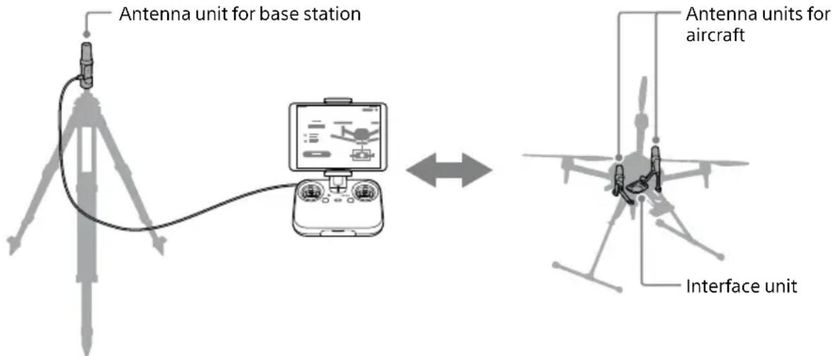
Connect the antenna unit for base station to the remote controller (sold separately)
Install the interface unit and antenna units for aircraft on the aircraft (sold separately)
- When using the GNSS correction service
You can also connect to the GNSS correction service* by configuring the network RTK function in the "Airpeak Flight" app on your mobile device.
You cannot use an antenna unit for base station when using the GNSS correction service.
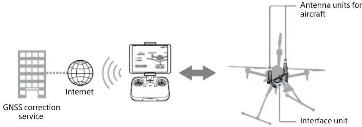
flowchart
graph LR
    A["GNSS correction service"] --> B["Internet"]
    B --> C["Analog device"]
    C --> D["Antenna units for aircraft"]
    D --> E["Interface unit"]
Connect to the GNSS correction service via the internet from your mobile device attached to the remote controller (sold separately)
Install the interface unit and antenna units for aircraft on the aircraft (sold separately)
* The GNSS correction service requires a contract with the distributor. For information such as service contents and usage methods, please contact the distributor.
Supported devices
For cameras and lenses supported by this product, please check our Customer Support Website. Select so that the total mass including this product is within the max takeoff mass of the aircraft. https://electronics.sony.com/airpeak/support/compatibility
Package contents
Contact the place of purchase or Sony Customer Support if any components are missing. Quantities are indicated in parentheses.
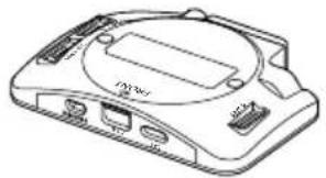
- Interface unit (1)
natural_image
Line drawing of a Sony 3.0 console with ports and casing (no text or symbols)• Antenna unit for aircraft (2)

natural_image
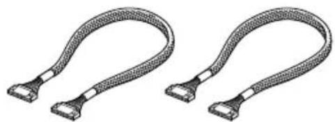
Technical line drawing of two mechanical device components (no text or symbols)- Antenna cable (2)
natural_image
Two identical curved cable or connector packages, shown in grayscale with no text or symbols.- Hot shoe cable (1)

natural_image
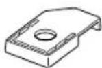
Simple line drawing of a cable with two connectors and a central screw (no text or symbols)• Hot shoe attachment (1)
At the time of purchase, this is attached to the hot shoe cable.
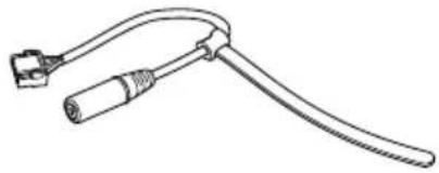
- Flash sync relay cable (1)
natural_image
Line drawing of a medical or laboratory device with a coiled cable and connector (no text or symbols)- Hex screw (10) (including two spare screws)

- M2 screw (4) (spare for installing the interface unit)

- Antenna unit for base station (1)
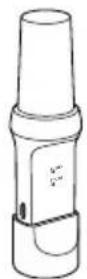
- Micro USB OTG cable (1)

natural_image
Line drawing of a USB cable connector with two connectors (no text or symbols)- USB Type-C® cable (remote controller-base station) (1)

natural_image
Line drawing of a USB cable with two connectors (no text or symbols)- Operating Instructions (this manual) (1)
- Warranty (1)
Guide to parts and controls
Interface unit
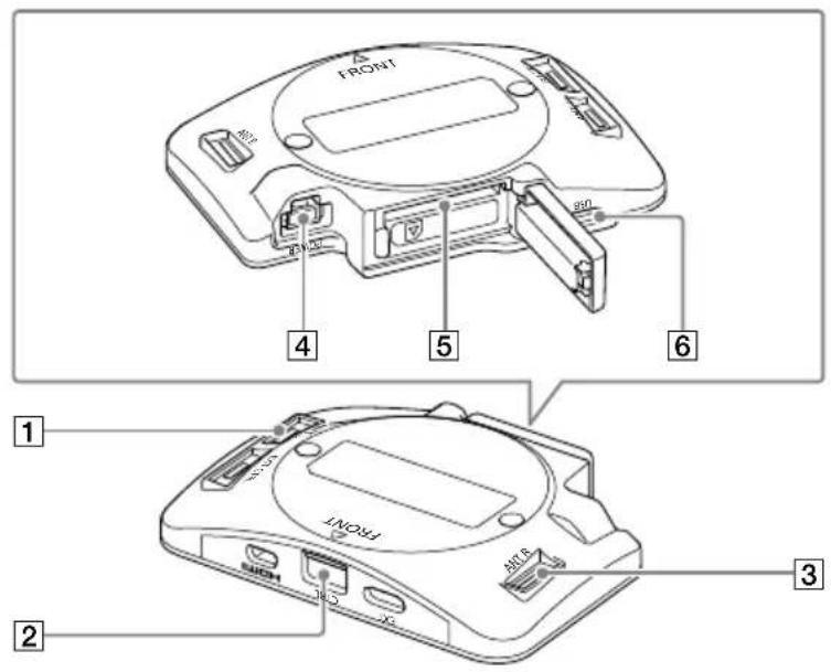
1 ANT L port
2 Control port
3 ANT R port
4 POWER port
5 SD memory card slot
6 USB port
Antenna unit for aircraft
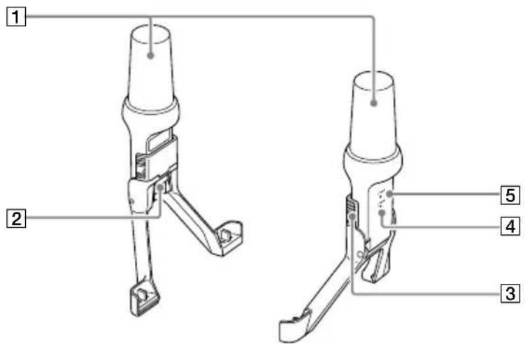
1 GNSS antenna
② ANT port
3 Lock slide
4 STATUS LED
Lights white when the RTK function is available. Blinks white while receiving correction data.
5 POWER LED
Lights green when the power is on.
Antenna unit for base station
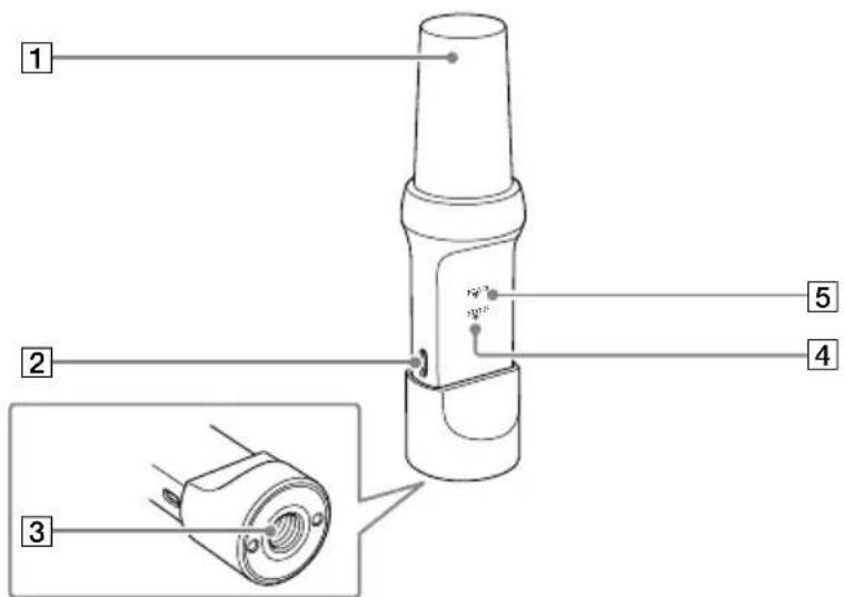
1 GNSS antenna
② USB port
3 Screw hole for tripod (5/8-11 UNC)
4 STATUS LED
The STATUS LED on the antenna unit for base station remains off even when the RTK function is available. However, specifications are subject to change depending on software updates.
5 POWER LED
Lights green when the power is on.
Connection/Installation
Preparing the app and the batteries
When you use the ARS-S1 for the first time, refer to the Startup Guide included with the ARS-S1 and follow the steps below.
"Mobile app 'Airpeak Flight' installation/initial setup" chapter
- "Installing the 'Airpeak Flight' app"
• "Signing in to the 'Airpeak Flight' app"
"Setup" chapter
- "Charging the batteries"
Mounting the RTK kit on the aircraft and assembling the aircraft
[1] Removing the damping plate from the aircraft
Be sure to turn off the aircraft before connecting/removing cables or the connection hub to/from the aircraft.
1 When using the aircraft with the damping plate already attached, remove the battery pack, propellers, and landing gear from the aircraft.
Refer to the ARS-S1 Startup Guide for how to remove each part.
To remove the landing gear, perform the work with the aircraft placed upside down on the packing box cushioning.
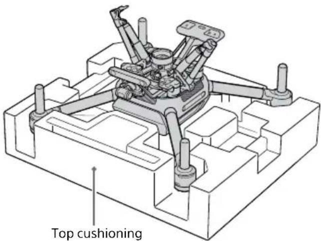
Note
When placing the aircraft upside down, be careful to keep the propeller attachment points of each motor off the surface.
2 Remove the cables from the quick-release ports.

Note
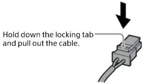
A locking mechanism is used on the control cable (aircraft — gimbal) and power cable (aircraft — gimbal). To release the lock, hold down the locking tab and pull out the cable.
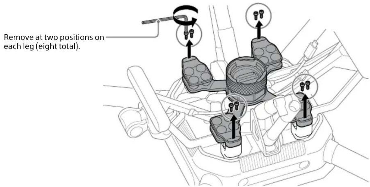
3 Remove the hex screws that secure the damping plate to the aircraft.
Remove the hex screws with the hex wrench (H2.5 mm) (0.1 in.) included in the gimbal set (sold separately).
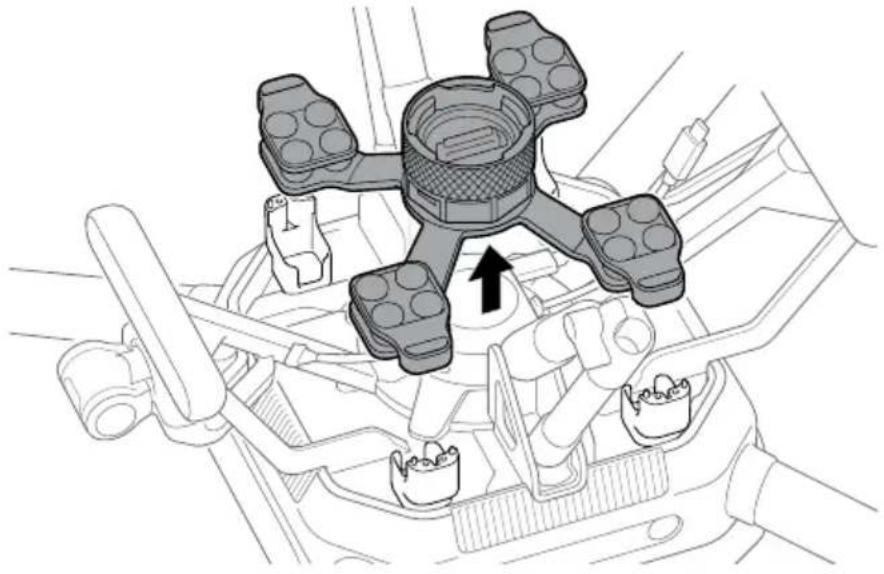
4 Remove the damping plate from the aircraft.
Remove the damping plate after removing the hex screws.
natural_image
Mechanical assembly diagram showing a multi-part component with a black arrow indicating direction (no text or symbols present)[2] Removing the connection hub from the aircraft
1 Remove the cables from the aircraft.
Remove the cables from the connection hub on the aircraft.
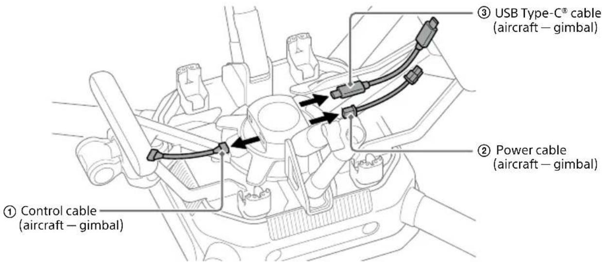
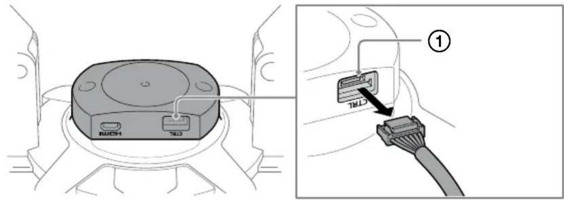
Front of aircraft
① Remove the control cable (aircraft — gimbal) from the control port.
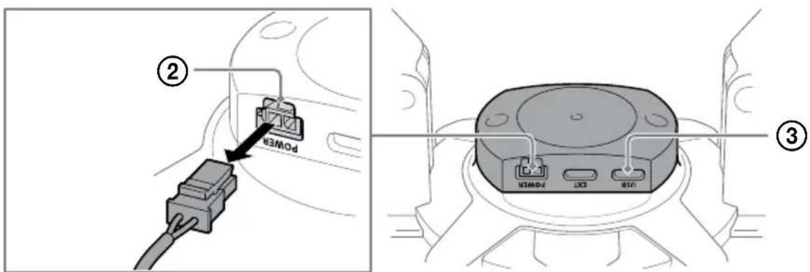
Rear of aircraft
② Remove the power cable (aircraft — gimbal) from the POWER port.
③Remove the USB Type-C® cable (aircraft — gimbal) from the USB port. If the USB Type-C® cable (aircraft — gimbal) is connected to the EXT port, remove the cable from the EXT port.
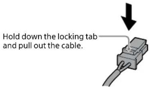
Note
A locking mechanism is used on the control cable (aircraft — gimbal) and power cable (aircraft — gimbal). To release the lock, hold down the locking tab and pull out the cable.
2 Remove the M2 screws that secure the connection hub to the aircraft.
Keep the M2 screws that you removed from the connection hub, as they will be used later. Remove at two positions.
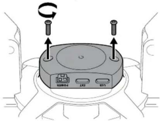
3 Remove the connection hub from the aircraft.

natural_image
Mechanical assembly diagram showing a component with an upward arrow, no visible text or symbols[3] Attaching the interface unit to the aircraft
1 Place the interface unit on the aircraft.
With the arrow indicating FRONT (①) pointing toward the front of the aircraft, place the interface unit on the aircraft connector. Push the interface unit fully until they are connected.
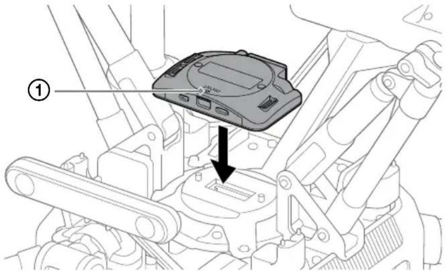
2 Secure the interface unit to the aircraft.
Secure the interface unit to the aircraft with the M2 screws removed in "[2] Removing the connection hub from the aircraft."
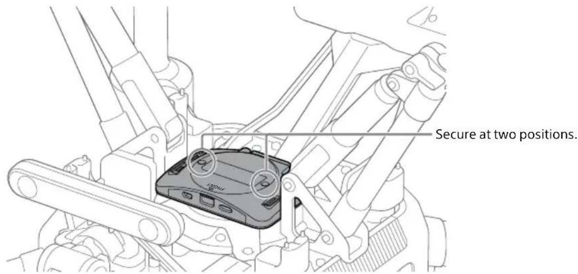
Note
When securing the interface unit to the aircraft, be sure to tighten the M2 screws with a torque of 0.2 ± 0.06 Nm.

If the removed M2 screws become lost, use the M2 screws included with this product.
[4] Connecting cables to the interface unit
Connect cables to the interface unit attached on the aircraft.
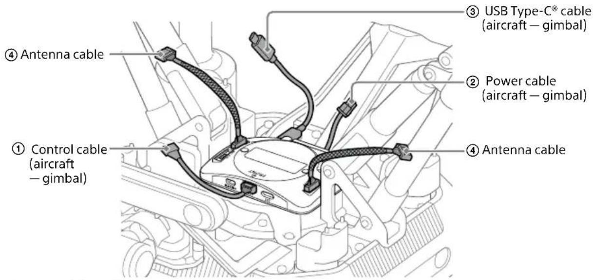
Front of aircraft

① Connect the control cable (aircraft — gimbal) to the control port.
Rear of aircraft
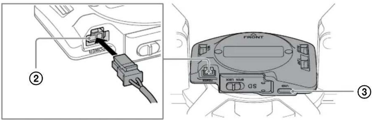
② Connect the power cable (aircraft — gimbal) to the POWER port.
③ Connect the USB Type-C® cable (aircraft — gimbal) to the USB port.
Bottom of aircraft

④ Connect the antenna cables to the ANT L/R ports.
Notes
- Connect the cables before attaching the damping plate, as it will be difficult to insert the cables once the damping plate is attached.
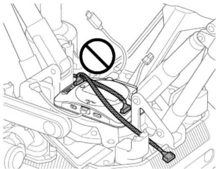
- The antenna cables on the right and left are the same part. Do not route the antenna cables with them crossed.
natural_image
Technical line drawing of a mechanical assembly with no visible text or symbols- Connect the USB Type-C® cable (aircraft — gimbal) to the USB port. Connecting the cable to the EXT port will not work.
- Use the USB Type-C® cable (aircraft — gimbal) that is included with the aircraft.
- A locking mechanism is used on the control cable (aircraft — gimbal), power cable (aircraft — gimbal), and antenna cable. Insert fully until the plug locks into place.
- The antenna cables have a braided tube. Be careful not to mistake them with the control cable (aircraft-gimbal).
[5] Attaching the damping plate and antenna units for aircraft to the aircraft
Note
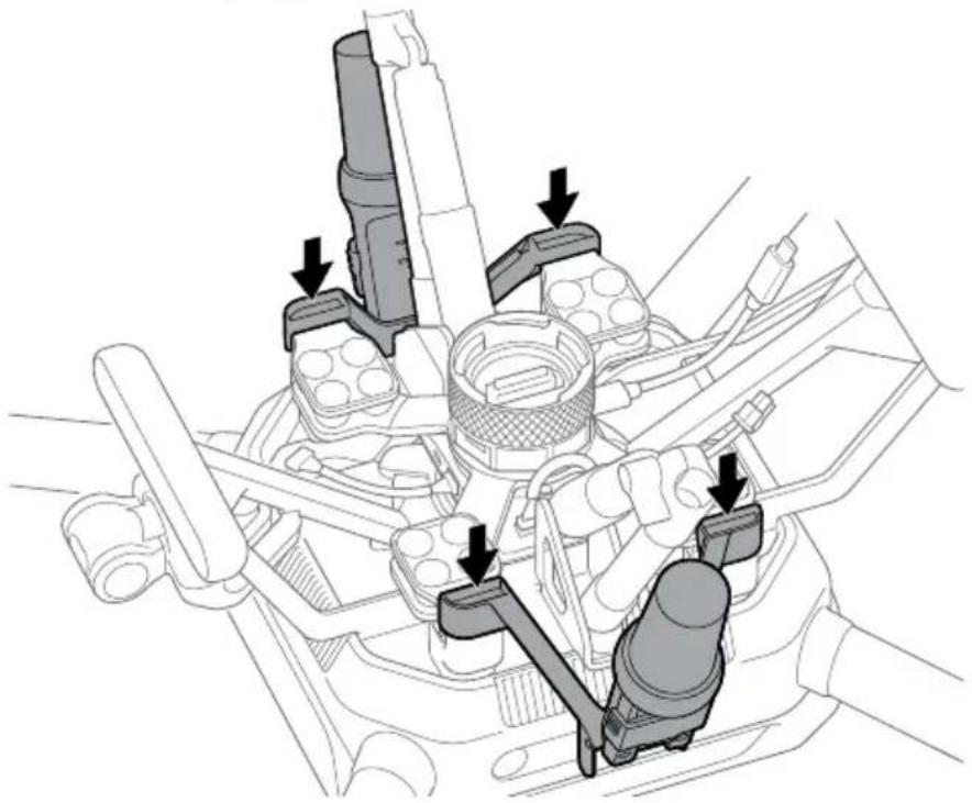
Be sure to attach the damping plate and antenna units for aircraft according to the following procedure. Installing them in the wrong order may cause deformation or damage to the parts. Also, the antenna units for aircraft may not be in the correct position, which may affect the aircraft's attitude control.
1 Confirm the orientation of the damping plate and place it on the aircraft.
With the quick-release arrow surface face-down and the arrow pointing toward the front of the aircraft, place the damping plate on the aircraft. Be careful not to get the cables caught between the damping plate and the aircraft.

2 Fold the antenna units for aircraft.
Hold the lock slides on both sides of the antenna units for aircraft and slide them toward the top of the antenna units for aircraft to unlock and fold the antenna units for aircraft.

3 Place the antenna units for aircraft on the aircraft.
Place the antenna units for aircraft on the left and right sides of the aircraft so that they cover the damping plate.
natural_image
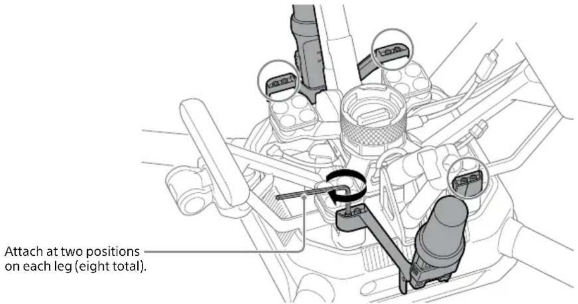
Technical diagram of a mechanical assembly with arrows indicating force or movement (no text or labels present)4 Secure the damping plate and the antenna units for aircraft using the hex screws included with this product.
Secure the screws using the hex wrench (H2.5 mm) (0.1 in.) included in the gimbal set (sold separately).
Notes
- Tighten the screws firmly using the hex wrench included in the gimbal set (sold separately). Otherwise, the screws may loosen and detachment may occur during flight.
- When using tools other than the hex wrench included in the gimbal set (sold separately), be sure to tighten the screws with a torque of 1.5 ± 0.5 Nm.
- Be sure to use the hex screws included with this product. The hex screws included with the gimbal set (sold separately) are too short to secure the damping plate and the antenna units for aircraft.
[6] Connecting cables to the quick-release
Insert the plugs at the other ends of the cables connected to the aircraft in the corresponding quick-release ports.
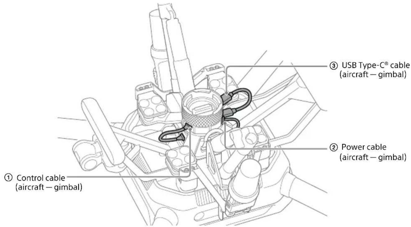
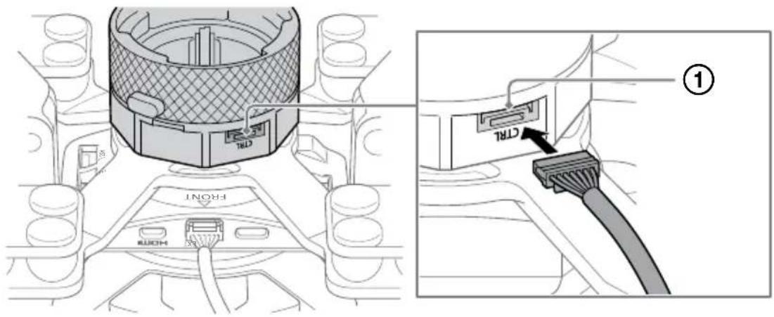
Front of aircraft
① Connect the control cable (aircraft — gimbal) to the control port.
Rear of aircraft
② Connect the power cable (aircraft — gimbal) to the POWER port.
③ Connect the USB Type-C® cable (aircraft — gimbal) to the USB port.

Note
A locking mechanism is used on the control cable (aircraft — gimbal) and power cable (aircraft — gimbal). Insert fully until the plug locks into place.
[7] Bringing the antenna cables out toward the antenna units for aircraft
1 Pass the antenna cable in a counterclockwise direction around the mounting part of the landing gear and bring it out toward the antenna unit for aircraft.
![SONY RTK-1 - [7] Bringing the antenna cables out toward the antenna units for aircraft - 1](/content/2026/05/1139946/images/8c3b5cadd4adaa6325d667c7afc8f6b02f2b6a83a14da3ec44fd61ee9d55cc19.jpg)
natural_image
Technical line drawing of automotive engine components including suspension bracket, valve, and lock assembly (no text or labels)2 Bring the other antenna cable out toward the antenna unit for aircraft in the same manner.
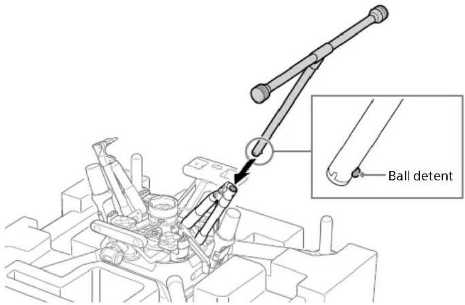
[8] Attaching landing gear to the aircraft
1 Press in the ball detent and insert the landing gear.
Make sure that the ball detent is fully engaged.
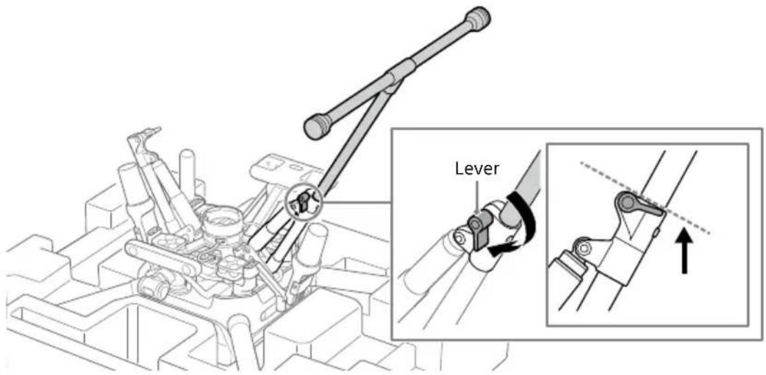
2 Turn the lever to lock the landing gear.
Turn both landing gear levers below the dotted line as shown below.
3 Attach the other landing gear in the same manner.
4 Turn the aircraft over.
Holding the aircraft securely by two frame arms, turn it over.
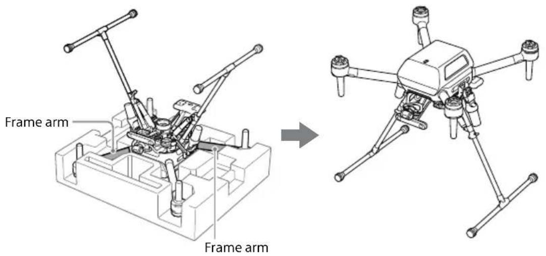
[9] Connecting cables to the antenna units for aircraft
1 Connect the antenna cable to the antenna unit for aircraft.
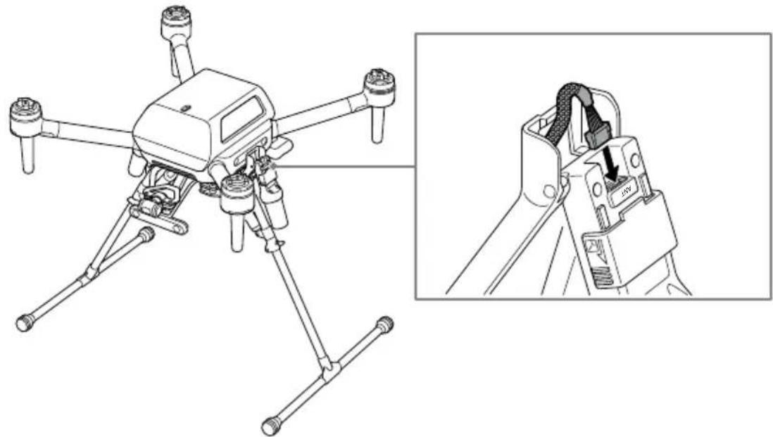
natural_image
Technical line drawing of a drone with extended wings and a close-up inset showing the internal structure (no text or symbols)2 Connect the other antenna cable to the antenna unit for aircraft in the same manner.
3 Raise the folded antenna units for aircraft.
After raising the antenna, push it in until it clicks into place. Make sure that the yellow label is invisible through the windows on the sides of the lock slides.
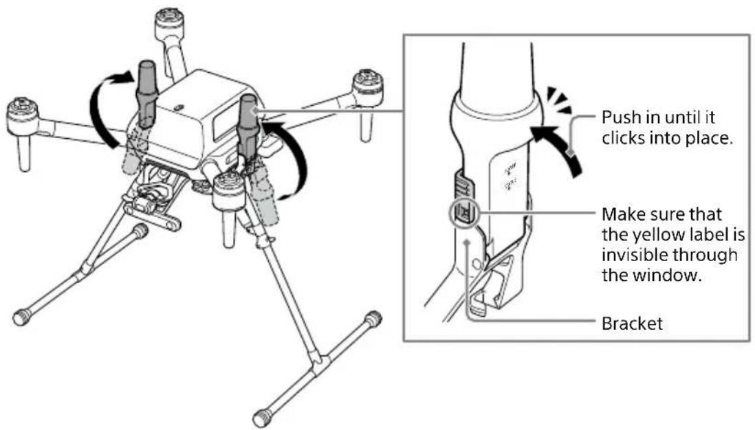
Notes
- Be sure to fold the antenna when connecting the antenna cable to the antenna unit for aircraft.
- A locking mechanism is used on the antenna cable. Insert fully until the plug locks into place.
- When raising the antenna unit for aircraft, make sure that the antenna cable is not pinched between the antenna and the bracket.
- Be careful not to let cables or other items catch on the raised antenna units for aircraft. The aircraft may topple over and come into contact with surrounding persons or items.
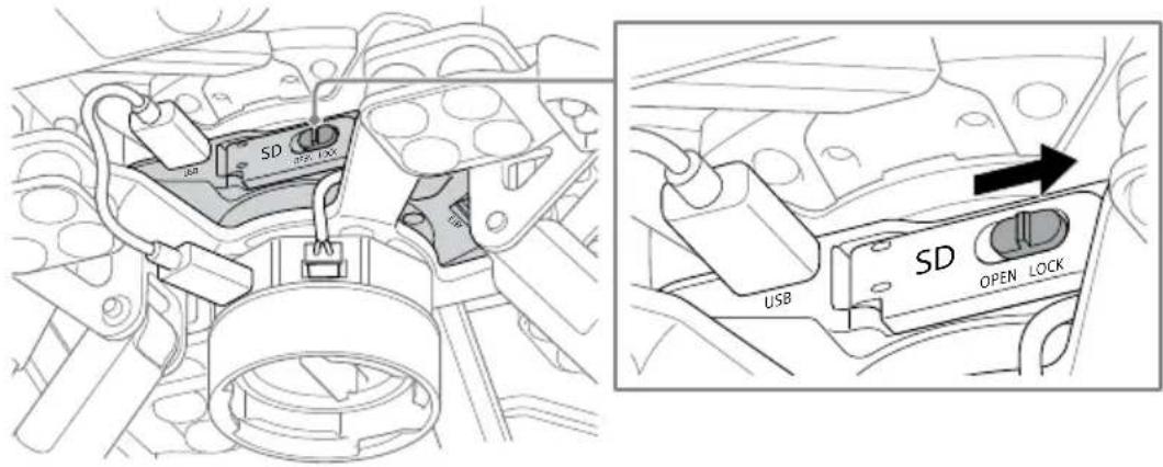
[10] Inserting an SD memory card
For information about SD memory cards that can be used with this product, refer to "Memory cards that can be used" (page 58).
1 Slide the switch on the SD memory card slot cover to unlock.

2 Open the SD memory card slot cover and insert an SD memory card.
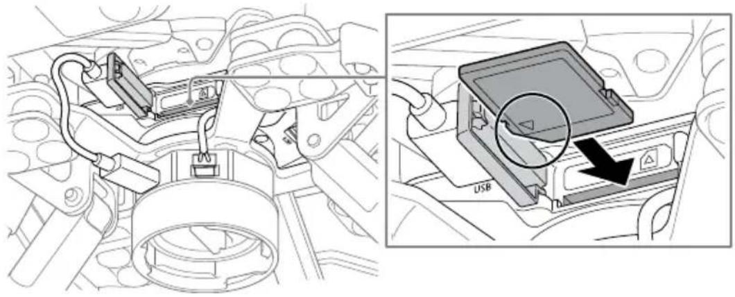
natural_image
Technical diagram showing engine compartment and USB port insertion (no text or symbols)3 Close the SD memory card slot cover and slide the switch to lock.
Notes
- Make sure that the SD memory card slot cover is securely locked before flight.
- Insert the SD memory card with the terminal surface facing up.
Installing the base station
Installation environment
• Install the antenna unit for base station on a tripod or the like to provide distance from the ground. If close to a water surface or object with a wide area, the multipath effect will prevent satellite signals from being received correctly.
- Make sure that there are no obstacles above or around the GNSS antenna of the base station.
- Do not install near high-voltage power lines, large-scale power transmission stations, mobile phone base stations, broadcasting towers, or other places where magnetic interference or radio interference are likely to occur.
- The distance between the antenna unit for base station and the antenna unit for aircraft should be within the wireless reachable range between the aircraft and the remote controller to be used.
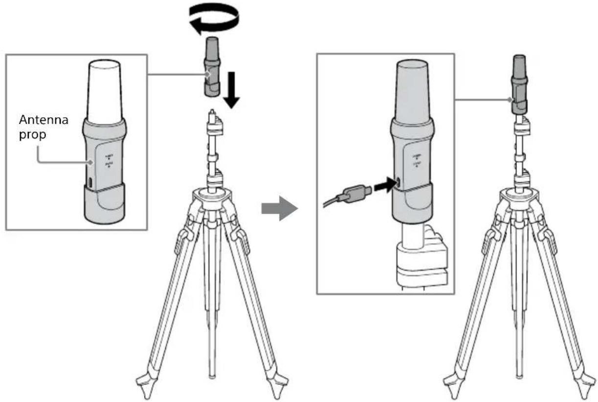
1 Install the antenna unit for base station on a tripod and connect USB Type-C® cable (remote controller-base station) to the antenna unit for base station.
The antenna unit for base station should be mounted on a tripod by gripping the antenna prop firmly, avoiding the antenna part.
Notes
- Attach the antenna unit for base station to a tripod with a 5/8-11 UNC screw. For a general camera tripod, use a thread diameter conversion adapter.
- When using a surveying tripod or other device equipped with a 5/8-11 UNC screw, set the tripod so that it does not fall over, such as using foot pressure to firmly set the feet into the ground or attaching weights, etc.
- When using a general camera tripod, take sufficient care to prevent it from toppling. Strong winds and pulling on the USB cable can easily topple the tripod, so prevent toppling by attaching weights, etc. to the legs of the tripod.
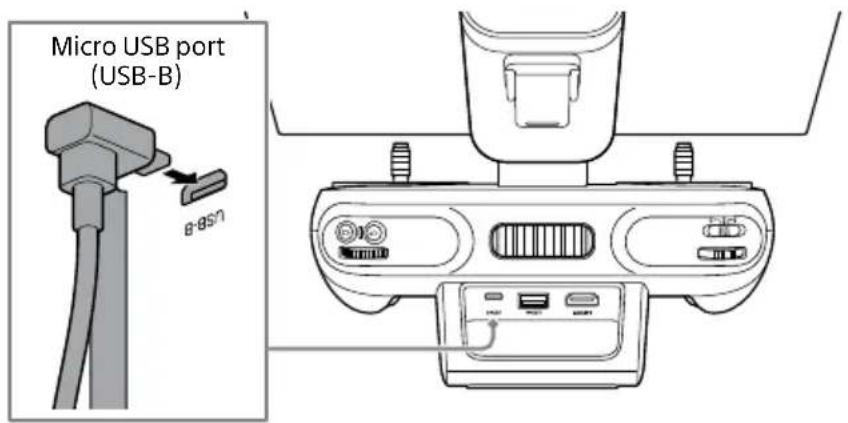
2 Connect the micro USB OTG cable to the micro USB port (USB-B) of the remote controller.
3 Peel the release paper off the fixing sheet attached to the micro USB OTG cable, and stick the fixing sheet on the back of the remote controller.
Before doing so, wipe any dust or debris off the area where the fixing sheet is to be stuck using a soft, dry cloth. Then, align the edge of the fixing sheet with the part separation line on the remote controller and attach the fixing sheet securely.

natural_image
Diagram showing a device's cable and adjustment mechanism before and after (no text or symbols)Part separation lineWipe off any dust or debris.
Notes
- Be sure to attach the fixing sheet to ensure stable communication between the antenna unit for base station and the remote controller.
- Do not detach the micro USB OTG cable once it is attached.
- Once the fixing sheet peels off, it cannot be reused because it loses its adhesive strength. If you need to replace the fixing sheet, such as in cases where the fixing sheet has peeled off, please refer to "If the fixing sheet becomes detached from the remote controller" (page 55).
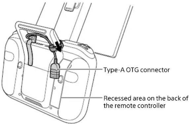
4 Secure the micro USB OTG cable to the left side of the handle bar with the hook-and-loop fastener.

Notes
- There is a communication antenna on the right side of the handle bar. To ensure stable wireless communication, do not secure the micro USB OTG cable to the right side of the handle bar.
- Do not secure the micro USB OTG cable to the top of the handle bar. If it is secured to the top of the handle bar, the hook-and-loop fastener will interfere with the packing box when the remote controller is stored in the packing box.
- When storing the remote controller in the packing box, place the Type-A OTG connector in the recess on the back of the remote controller and bring the hook-and-loop fastener toward the underside of the handle bar. If the hook-and-loop fastener is secured to the upper side of the handle bar, the hook-and-loop fastener will interfere with the packing box during storing.
5 Connect the micro USB OTG cable and the USB Type-C® cable (remote controller-base station).
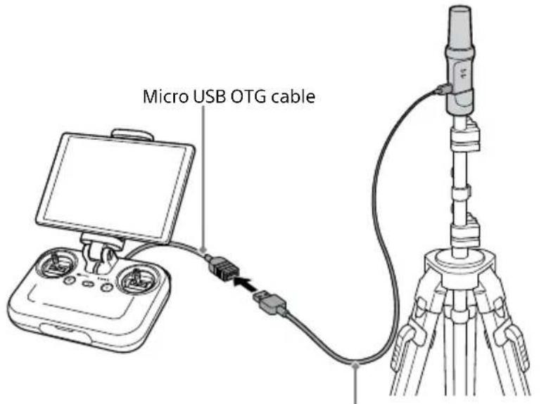
USB Type-C ^® cable (remote controller-base station)
Notes
- When connecting the USB Type-C® cable (remote controller-base station) to the remote controller, be sure to connect to the micro USB port (USB-B) of the remote controller via the micro USB OTG cable. Do not connect directly to the USB port (USB-A) of the remote controller.
- Be careful not to pull on the USB Type-C® cable (remote controller-base station) or catch it with your feet. The tripod on which the antenna unit for base station is installed may topple and come into contact with surrounding persons or items, or the cable may become disconnected, stopping transmission of correction data to the aircraft and affecting the flight of the aircraft.

Hint
When using in dual operation mode, the remote controller to be connected to the antenna unit for base station can be selected from [Main] or [Sub] by the "Airpeak Flight" app configuration.
Preparing the remote controller and the aircraft
When you use the ARS-S1 for the first time, refer to the Startup Guide included with the ARS-S1 and follow the steps below.
"Setup" chapter
- "Attaching a mobile device to the remote controller"
- "Loading battery packs in the aircraft"
- "Linking/setting up the remote controller and aircraft"
Preparing a camera
Prepare the camera before mounting it on the gimbal. (Both the camera and gimbal are sold separately.)
[1] Inserting a battery pack and memory card
Insert a battery pack and memory card in the camera in advance. (ILCE-7RM5 is used in this example.)
Battery pack
![SONY RTK-1 - [1] Inserting a battery pack and memory card - 1](/content/2026/05/1139946/images/3f419ec286e725d74285ba1b5106c6ecc35963dd4328cf81d3ed00eb55c9ccec.jpg)
natural_image
Diagram of a camera module with a close-up view showing internal components (no text or symbols)Memory card
![SONY RTK-1 - [1] Inserting a battery pack and memory card - 2](/content/2026/05/1139946/images/24e4d54bbe53999838a0899062ce404a4ed5907b8dc4e26f0d5e24931c6b280c.jpg)
natural_image
Line drawing of a DSLR camera with an open lid and internal components (no text or symbols)Notes
- During flights, cameras consume battery power as you shoot. Always charge the camera battery sufficiently before mounting on the gimbal.
- Use memory cards with sufficient free space for recording images.
- Make sure that the camera's battery cover is securely closed and locked.
[2] Configuring required settings on the camera
Configure the following setting items on the camera. For setting instructions, refer to the camera operating instructions or online Help Guide (Web manual).
- [PC Remote Function] — [PC Remote]: [On]
- [PC Remote Function] — [Still Img. Save Dest.]:
- [PC+Camera]: Captured still images are saved to the camera, and the geotags of the captured still images are stored on the SD memory card inserted into the RTK interface unit and in Airpeak Base. The thumbnail functions for captured still images are available in the “Airpeak Flight” App.
- [Camera Only]: Captured still images are saved only to the camera. The geotags of the captured still images are not stored on the SD memory card inserted into the RTK interface unit or in Airpeak Base. The thumbnail functions for captured still images are not available in the "Airpeak Flight" App.
- [Ctrl w/ Smartphone] — [Ctrl w/ Smartphone]: [Off]
• [USB Power Supply]: [Off]
- [File Format]: [RAW+JPEG] or [JPEG]
- [Shutter Type]:
– [Mechanical Shutter]: The geotags of the captured still images are stored on the SD memory card inserted into the RTK interface unit and in Airpeak Base.
– [Electronic Shutter]: The geotags of the captured still images are not stored on the SD memory card inserted into the RTK interface unit or in Airpeak Base.
Note
Be sure to set the Bluetooth function of the camera to [Off]. If it is set to [On], it may affect the wireless transmission function.

When the camera is attached to the gimbal and operated, the eye sensor of the camera may react, and the monitor may turn off/on. You can keep the monitor off or on at all times by selecting a setting other than [Auto] for [Select Finder/Monitor] on the camera.
Mounting the gimbal on the aircraft

WARNING
Carefully follow these instructions. Errors in set-up may cause the camera to detach and fall from the aircraft when in flight, which could result in injury or property damage.
1 Make sure the aircraft is off.
Confirm that the power status LED of the aircraft is off.
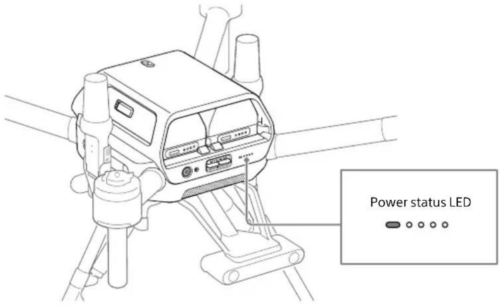
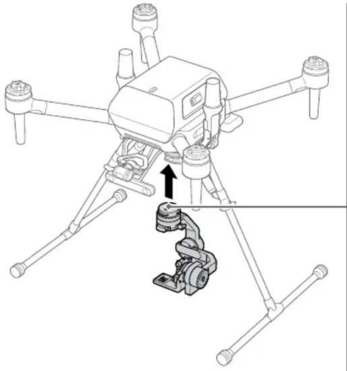
2 Mount the gimbal on the aircraft.
With the marks on the gimbal and quick-release aligned, attach the gimbal. Turn the ring toward the lock icon ( 🔒 until it clicks and locks into place.
natural_image
Technical line drawing of a quadcopter drone with extended wings and a mechanical assembly below (no text or symbols)
Mounting a camera on the gimbal (when using the GBL-PX1)
The installation procedure differs depending on the gimbal. Mount the camera on the gimbal according to the instructions for your gimbal.
[1] Attach the L-Bracket to the camera
Note
Be careful not to get your fingers caught when operating the lever.
1 Remove the shoulder strap attachment from the camera.

Note
Store the shoulder strap attachment securely so as not to lose it.
2 Remove the L-Bracket from the gimbal.
Loosen the lever, and move the L-Bracket forward to remove it while pressing the release button at the bottom.
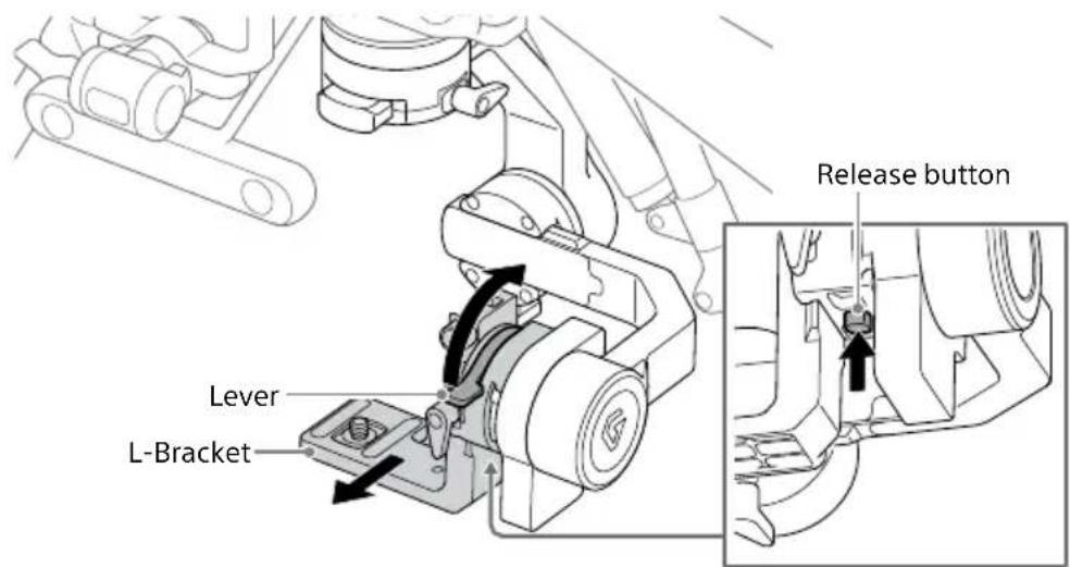
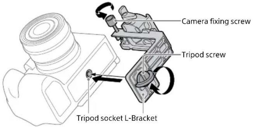
3 Loosen the camera fixing screw, and temporarily attach the tripod screw on the L-Bracket to the tripod socket on the bottom of the camera.
Make sure there is a gap of about 1 mm (0.04 in.) between the L-Bracket and the bottom of the camera.
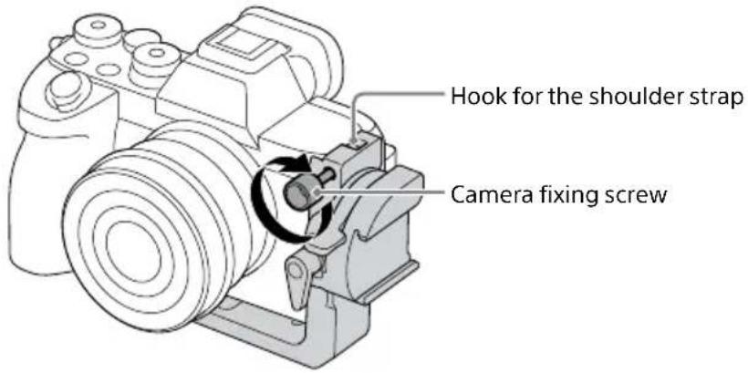
4 Pass the camera fixing screw through the hook for the shoulder strap on the camera and secure it.
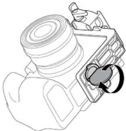
5 Use a coin, etc. to fully tighten the tripod screw.
natural_image
Technical line drawing of a mechanical component with a circular arrow indicating rotation (no text or symbols)Notes
- Before flights, make sure the camera is firmly secured to the L-Bracket with the tripod screw and camera fixing screw.
- When removing the camera from the L-Bracket, perform the reverse procedure.
[2] Mounting the camera on the gimbal
1 Place the camera in the gimbal.
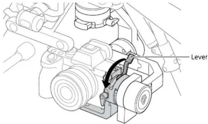
Unlock the lever and place the camera in the gimbal from the front.

2 Secure the camera in the gimbal.
Lock the lever.
[3] Connecting cables between the camera and gimbal
1 Connect the USB Type-C® cable (gimbal — camera) to the camera and the gimbal.
Insert the plug of the USB Type-C® cable (gimbal — camera) included with the aircraft in the camera USB port.
Insert the other end of the USB Type-C® cable (gimbal — camera) connected to the camera in the gimbal USB port.
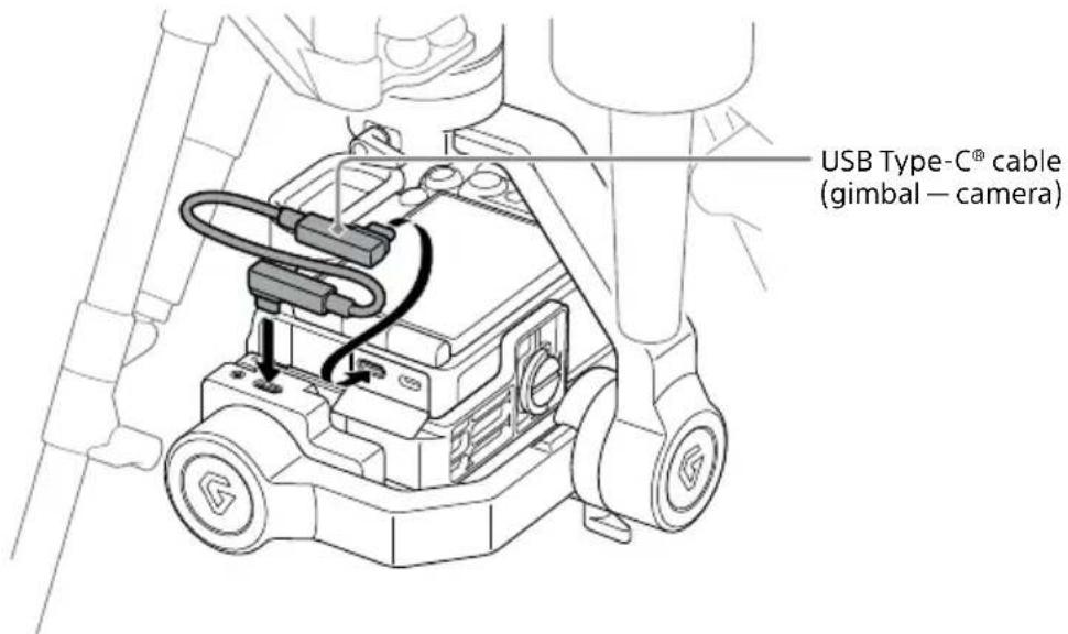
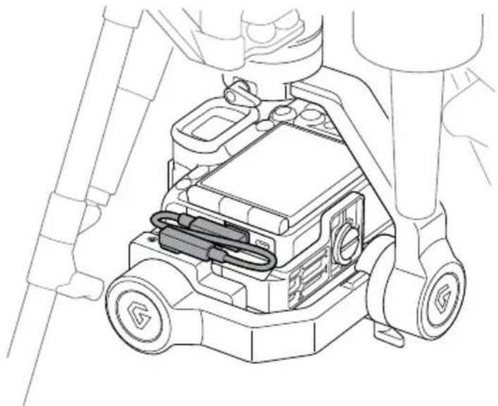
2 Make sure that the USB Type-C® cable (gimbal — camera) is properly connected.
Make sure that the USB Type-C® cable (gimbal — camera) is wired in an S shape so as not to interfere with the gimbal.
natural_image
Technical line drawing of a mechanical assembly with no visible text or symbolsNote
If you wire the USB Type-C® cable (gimbal — camera) in a U shape, there is a possibility of it coming into contact with the frame while the aircraft is in use. Wire the USB Type-C® cable (gimbal — camera) so that it forms an S shape.
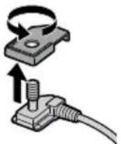
3 Remove the hot shoe attachment from the hot shoe cable included with this product.
Hint
The hot shoe attachment is a part used when mounting the camera on the gimbal GBL-T3. Store the hot shoe attachment securely so as not to lose it.
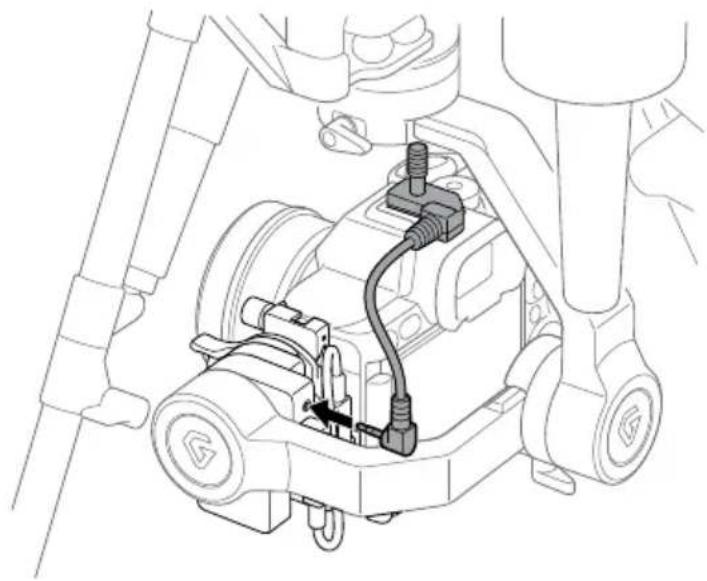
4 Attach the hot shoe cable to the camera.

5 Connect the hot shoe cable to the gimbal.
Insert the other end of the hot shoe cable attached to the camera in the gimbal SYNC port.
natural_image
Technical line drawing of a mechanical assembly with no visible text or symbols[4] Adjusting the balance of the gimbal
Adjust the balances of the tilt, roll, and pan axes.
Note
Be careful not to get your fingers caught in the tilt frame, roll frame, or pan frame when adjusting the balance of the gimbal.
Preparation
- Confirm that the camera lens cap is removed.
- Confirm that the camera and gimbal are connected using the USB Type-C® cable (gimbal — camera) (page 37).
- When using the RTK kit, confirm that the camera and gimbal are connected using the hot shoe cable (page 38).
- Turn on the camera to avoid movements of the focus unit in the lens.
- Confirm that the aircraft is turned off.
- Confirm that you have installed all the accessories you want to use.
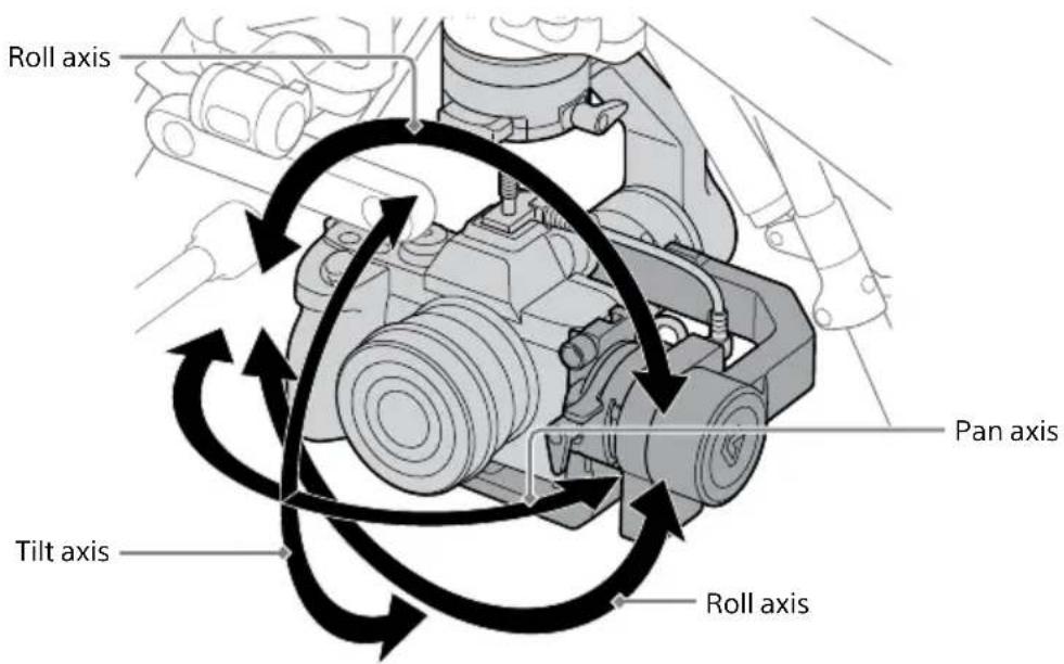
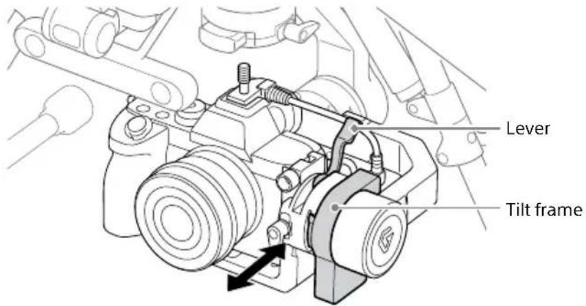
1 Adjust the balance of the tilt axis.
Adjust the horizontal and vertical balances of the tilt axis.
Horizontal balance adjustment of the tilt axis
① Loosen the lever, and then slide the L-Bracket forward or backward to adjust the balance.
② After adjusting the balance, close the lever firmly.
③ Rotate the tilt frame by about ±15^ to check if the balance is adjusted properly. If properly adjusted, the tilt frame will stay still or return to the horizontal position.
Vertical balance adjustment of the tilt axis
① Rotate the gimbal L-Bracket to aim the camera lens downward.
② Loosen the lever on the front of the L-Bracket and slide the L-Bracket back and forth to adjust the balance.
③ After adjusting the balance, firmly tighten the lever.
④ Rotate the tilt frame by about ±45^ to check if the balance is adjusted properly. If properly adjusted, the tilt frame will stay still, or the camera lens will return to facing down.
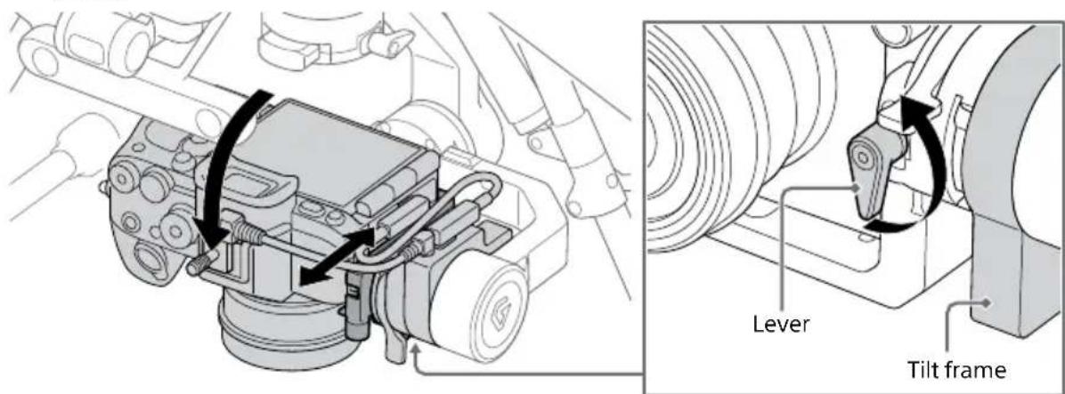

If the lever interferes with surrounding parts, pull the lever toward you and turn it to avoid interference.

natural_image
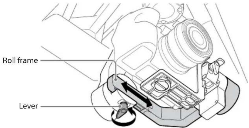
Mechanical assembly diagram showing a lever mechanism with rotating components (no text or labels)2 Adjust the balance of the roll axis.
① Loosen the lever and slide the roll frame left and right to adjust the balance.
② After adjusting the balance, firmly tighten the lever.
③ Rotate the roll frame by about ±45^ to check if the balance is adjusted properly. If properly adjusted, the roll frame will stay still or slowly return to the horizontal position.
3 Adjust the balance of the pan axis.
① Loosen the lever and slide the pan frame back and forth to adjust the balance.
② After adjusting the balance, firmly tighten the lever.
③ With the gimbal stationary, tilt the aircraft forward, backward, left, and right to check if the balance is adjusted properly. If properly adjusted, the pan frame will stay still.


natural_image
Diagram showing two identical mechanical setups with articulated legs and a camera, illustrating the change in assembly or positioning (no text or symbols present)Note
Do not adjust the gimbal balance with the aircraft upside down. Doing so may deteriorate or damage the damping rubber of the damping plate.
[5] Adjusting the gimbal parameters
The gimbal parameters need to be adjusted.
Visit the support site for details on adjustment.
http://electronics.sony.com/airpeak/p/gblpx1/settings
Mounting a camera on the gimbal (when using the GBL-T3)
The installation procedure differs depending on the gimbal. Mount the camera on the gimbal according to the instructions for your gimbal.
[1] Attaching the camera plate and hot shoe cable to the camera
The camera plate is included in the gimbal GBL-T3 set (sold separately). Use the hot shoe cable included with this product.
1 Attach the camera plate included with the gimbal set to the camera.
Attach the camera plate (included with the GBL-T3) to the tripod socket on the bottom of the camera. Temporarily attach the thumbscrew to the tripod socket by tightening it.
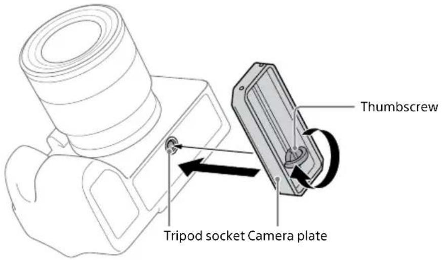
2 Use a coin, etc. to fully tighten the thumbscrew.

natural_image
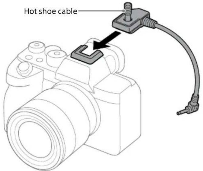
Technical line drawing of a mechanical component with a circular arrow indicating rotation (no text or symbols)3 Attach the hot shoe cable included with this product to the camera.
Notes
- When using the gimbal GBL-T3 set (sold separately), be sure to use the hot shoe attachment. Otherwise, the camera may not be secured properly on the gimbal.
- If the hot shoe attachment has become detached from the hot shoe cable, insert the opening of the hot shoe attachment into the thread of the hot shoe cable by turning it clockwise.

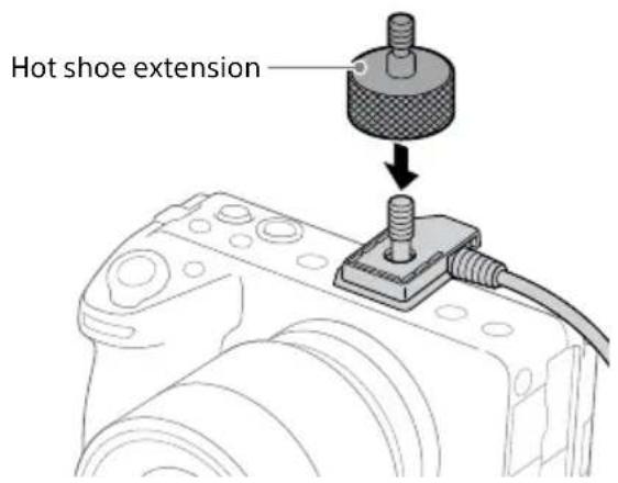
To use a camera with a short height
When using a camera with a short height such as the ILME-FX3 or ILCE-7C, attach the hot shoe extension to the hot shoe cable. The hot shoe extension is included in the gimbal set (sold separately).
[2] Connecting the flash sync relay cable to the gimbal and securing it
1 Connect the flash sync relay cable to the AUX port of the gimbal.
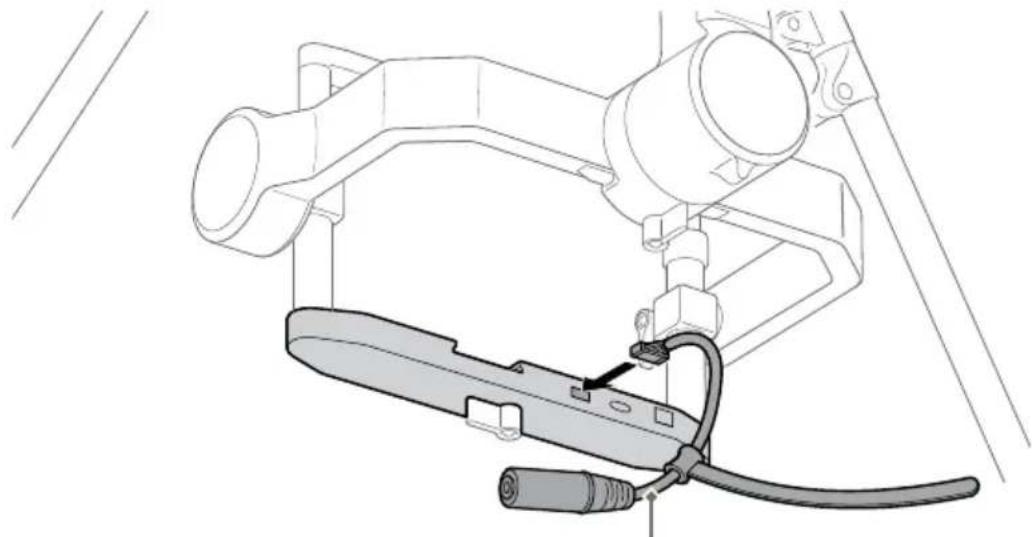
natural_image
Technical line drawing of a mechanical assembly with no visible text or symbolsFlash sync relay cable
2 Secure the flash sync relay cable to the bottom part of the gimbal frame with the hook-and-loop fastener.
Pass the hook-and-loop fastener under the frame, turn it forward, and then pass it over the frame to bundle it. Bundle it on the left side of the groove on the frame when viewed from the rear.

Notes
- When storing the gimbal in the packing box, do not remove the flash sync relay cable. Leave it secured to the gimbal.
- The flash sync relay cable should be bent down at the connector end and secured using the hook-and loop-fastener along the underside of the gimbal frame. If the cable is secured on the upper side of or right beside the gimbal frame, the USB cable to be connected in a subsequent procedure may stick up and be unable to be connected properly.
[3] Mounting a camera on the gimbal
1 Place the camera in the gimbal.
Loosen the locking screws on both sides of the gimbal frame, extend the tilt top bar to make it higher, and place the camera in the gimbal from the front. Slide the camera plate attached to the camera into the groove on the bottom part of the frame.
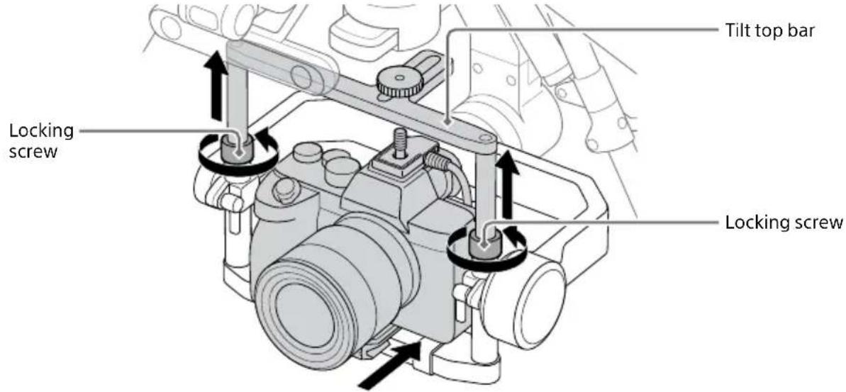
2 Secure the camera in the gimbal.
Lower the tilt top bar, tighten the locking screws on both sides, and tighten the top camera screw on the hot shoe cable screw. Tighten the lever on the bottom of the frame to secure the camera.
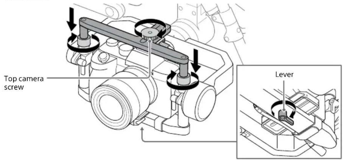
Note
Be careful not to get your fingers caught in the tilt top bar when securing the camera in the gimbal.
[4] Connecting cables between the camera and gimbal
Connect the flash sync relay cable to the hot shoe cable, and connect the camera and the gimbal with the USB cable included with the aircraft.
1 Connect the flash sync relay cable to the hot shoe cable.
Connect the hot shoe cable to the connector of the flash sync relay cable.
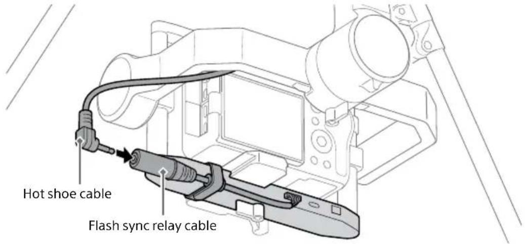
2 Connect the USB cable to the camera and the gimbal.
Insert the plug of the USB Type-C® cable (gimbal — camera) included with the aircraft or micro USB cable (gimbal — camera) into the camera USB port. Connect the USB cable that matches your camera port.
Insert the other end of the USB cable connected to the camera in the gimbal USB port.
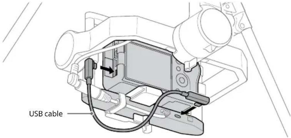
Notes
- Positions of camera ports vary by camera.
- If you adjust the tilt axis of the gimbal, the hot shoe cable and USB cable may come into contact with the frame of the gimbal. Route the cables so that they do not come into contact with the gimbal frame.
- Before removing the camera from the gimbal, disconnect the hot shoe cable or pull out the pin jack. Be careful not to pull out the flash sync relay cable from the gimbal.
[5] Adjusting the balance of the gimbal
Notes
- Be careful not to get your fingers caught in the tilt frame, roll frame, or pan frame when adjusting the balance of the gimbal.
- When using the RTK kit, confirm that the camera and gimbal are connected using the hot shoe cable and flash sync relay cable before starting to adjust the balance of the gimbal (page 47).
1 Refer to the Startup Guide included with the ARS-S1 and follow the steps below.
"Gimbal and camera mounting" chapter
- “[4] Adjusting the balance of the gimbal” under “Mounting a camera on the gimbal”
Under step 1, perform ① in "Horizontal balance adjustment of the tilt axis."
2 Confirm that the hot shoe cable is not disconnected from the camera's shoe terminal.
3 Refer to the Startup Guide included with the ARS-S1 and follow the steps below.
"Gimbal and camera mounting" chapter
- “[4] Adjusting the balance of the gimbal” under “Mounting a camera on the gimbal”
Perform all the operations that follow ② in "Horizontal balance adjustment of the tilt axis" under step 1 to adjust the balance of the tilt, roll, and pan axes.
[6] Adjusting the gimbal parameters
The gimbal parameters need to be adjusted.
Visit the support site for details on adjustment.
http://electronics.sony.com/airpeak/p/gblt3/settings
Setting up
Updating to the latest software
To use this product, it is necessary to update to the latest system software. Update in the condition with the aircraft and the remote controller connected and the mobile device attached to the remote controller connected to the internet.
1 Tap [Start flight] in the "Airpeak Flight" app home page.
The flight screen will be displayed.
2 Tap (Settings) in the top right of the screen.
3 Tap [General] in the displayed setting menu.
4 Tap [Maintenance].
5 Tap [Update] for [System software].
The update wizard will start.
Follow the instructions on the screen to complete the update.
Notes
- To use this product, the software versions of the aircraft, the remote controller, and the "Airpeak Flight" app must be 2.0.0 or later. If the software versions of the aircraft and the remote controller are outdated, this product will not be recognized. Also, if the "Airpeak Flight" app version is outdated, the setting menu and other information of this product will not be displayed.
- Approximately 50 minutes is needed to update the aircraft, remote controller, and RTK kit software. Please allow plenty of time in advance and update the software.

If a system software update is available, a notification will be displayed on the "Airpeak Flight" App Home page.
Making the RTK kit settings
Refer to the ARS-S1 Help Guide for a description of operations and settings.
ARS-S1 Help Guide (Web manual)

https://rd1.sony.net/help/airpeak/arss1/en/
Flying
[1] Attaching the propellers
Refer to the Startup Guide included with the ARS-S1 and follow the steps below.
"Flights" chapter
- "Attaching the propellers"
[2] Checking error messages in the flight screen
Error messages can be checked by accessing the flight screen from the "Airpeak Flight" app home page.
1 Tap [Start flight] in the "Airpeak Flight" app home page.
2 Confirm that no error messages are displayed on the flight screen.
Confirm that no warnings, cautions, or dialogs are displayed.
[3] Checking settings and status
Settings and status can be checked from the setting menu on the flight screen.
1 Tap (Settings) to open the setting menu.
2 Check the settings and status.
Check the status of these items in the [Aircraft], [Remote controller], and [RTK] categories.
Aircraft status
- Flight mode: [Aircraft] — [Flight mode]
• Maximum flight altitude: [Aircraft] — [Safety functions] — [Maximum altitude] - Wireless performance: [Aircraft] — [Sensors/Radio]
■ Remote controller status
- Remote controller operation mode: [Remote controller] — [Connection]
- Remote controller battery: [Remote controller] — [Details] — [Battery details]
Battery pack status
- Aircraft battery packs: [Aircraft] — [Batteries]
- Aircraft battery pack temperature: [Aircraft] — [Batteries]
■ RTK kit status
- System: [RTK] – [System]
- Base station: [RTK] – [Base station]
- Network station: [RTK] – [Network station]
[4] Flying the aircraft
Refer to the ARS-S1 Help Guide. General instructions for operating the ARS-S1, including flight plans and maneuvering the aircraft, are described.
Also, refer to the following steps in the Startup Guide included with the ARS-S1. Some operations are described.
"Flights" chapter
- "Flying and shooting video"
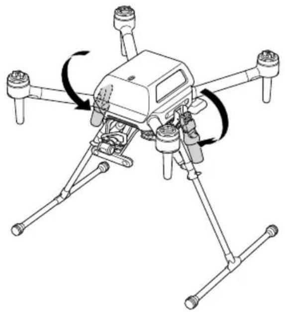
Folding the antenna units for aircraft
1 Hold the lock slides on both sides of the antenna units for aircraft and pull upward.
The antenna units for aircraft are unlocked.

2 Fold the antenna units for aircraft.
natural_image
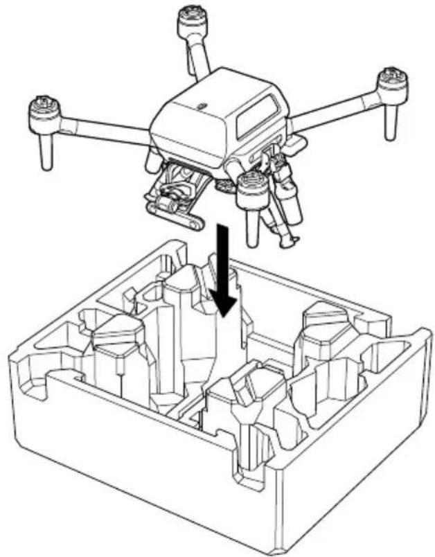
Line drawing of a quadcopter drone with four propellers and four legs, showing rotational motion (no text or symbols)Storing in the packing box
You can store the aircraft in the packing box with the antenna units for aircraft installed. When storing, remove the landing gear from the aircraft and be sure to fold the antenna units for aircraft.
natural_image
Technical line drawing of a drone with four propellers and a mechanical component below (no text or symbols)Flight Information and Specifications
Flight Precautions
- Be careful not to cover the GNSS antenna parts of the antenna units for aircraft and the antenna unit for base station by mistake. Doing so may affect the attitude control of the aircraft.
- Do not fly the aircraft without the antenna units for aircraft raised. Doing so may affect the attitude control of the aircraft or cause damage to the antenna units for aircraft.
- Check the version numbers of the "Airpeak Flight" app and system software of the aircraft and remote controller to confirm that they are up to date.
- When using the GNSS correction service instead of the antenna unit for base station, use the mobile data communication function of the tablet or other mobile device mounted on the remote controller. Turn off the Wi-Fi® and Bluetooth® functions and do not use them.
Notes on use
About heat generation
The interface unit and the inserted SD memory card may become hot during operation, but this does not affect operation.
Carrying components
Do not carry the aircraft by holding the GNSS antenna section of the antenna units for aircraft installed on the aircraft. Doing so may damage the GNSS antenna and cause damage or injury if the aircraft is dropped.
Installing external devices
The USB port of this product can supply up to 900 mA of current (if the external device supports USB 3.2). If overcurrent conditions exceeding 900 mA occur while an external device is installed, it may affect flight performance.
Maintenance and storage
- The recommended ambient temperature range for storage is 18^ (64°F) to 30^ (86°F).
- Thoroughly wipe off any water that has adhered to the aircraft and this product before storing them.
- Gently wipe off any dirt or dust on this product with a soft, dry cloth.
- Do not use volatile substances such as alcohol or paint thinner, as they may damage the parts and cause deterioration.
Troubleshooting
If you experience trouble with the product, try the following solutions.
① Cycle the power.
Interface unit, antenna unit for aircraft:
Turn off the power of the aircraft on which this product is installed and remove both battery packs. After about 1 minute, reinsert the battery packs and turn the power back on.
Antenna unit for base station:
Turn off the power of the connected remote controller and then turn it back on after about 1 minute.
② Check the additional information on our Customer Support Website.
https://www.sony.com/electronics/support
③ Consult Sony Customer Support.
If the fixing sheet becomes detached from the remote controller
The fixing sheet attached to the micro USB OTG cable is available for purchase.
Please consult Sony Customer Support. Instructions for attaching a new fixing sheet to the micro USB OTG cable are as follows.
1 Remove the old fixing sheet from the micro USB OTG cable.
2 Wipe any remaining glue or dust off the area where the fixing sheet was stuck to the micro USB OTG cable using a soft, dry cloth.
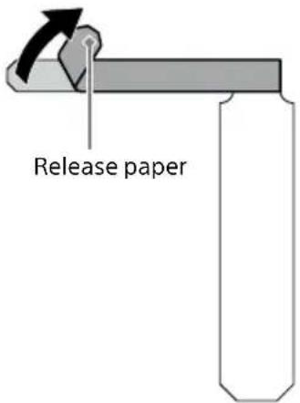
3 Peel the release paper off the transversely extending fixing sheet.
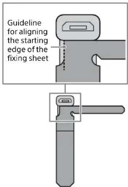
4 With the USB plug of the micro USB OTG cable toward you, align the starting edge of the fixing sheet with the dotted line shown below, using the beginning of the lower left curve of the USB plug as a guide, and attach the adhesive side.
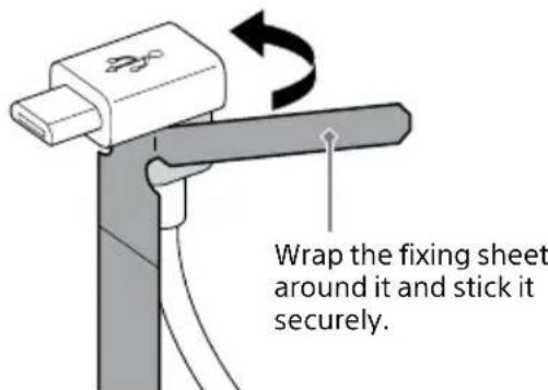
5 Wrap and stick the fixing sheet counterclockwise around the support under the USB plug.
Specifications
Model
RTK-1
Dimensions
Interface unit: Approx. 19 mm (0.75 in.) × 86 mm (3.5 in.) × 64 mm (2.63 in.) (H × W × D)
Antenna unit for aircraft: Approx. 191 mm (7.63 in.) × 130 mm (5.13 in.) × 56 mm (2.25 in.) (H × W × D)
Antenna unit for base station: Approx. 152 mm (6.0 in.) × 41 mm (1.63 in.) × 41 mm (1.63 in.) (H × W × D)
Mass
Interface unit: Approx. 55 g (2.0 oz)
Antenna unit for aircraft: Approx. 84 g (3.0 oz)/per unit
Antenna unit for base station: Approx. 105 g (3.7 oz)
Operating Temperature
-10 °C (14 °F) - 40 °C (104 °F)
Hovering Accuracy (\*1)
Vertical: ±0.1 m (0.3 ft), Horizontal: ±0.1 m (0.3 ft) (RTK enabled)
Vertical: ±0.1 m (0.3 ft), Horizontal: ±0.1 m (0.3 ft) (GNSS (*2) and Vision Positioning enabled)
Vertical: ±0.5 m (1.6 ft), Horizontal: ±0.5 m (1.6 ft) (GNSS (*2) enabled and Vision Positioning disabled)
*1 When the RTK kit is attached to the aircraft
*2 When not using the RTK function of the RTK kit and performing GNSS single point positioning
RTK positioning accuracy\*
Horizontal: 1 cm + 1 ppm, Vertical: 1.5 cm + 1 ppm
* When the RTK function is available
GNSS
GPS, GLONASS, Galileo, BeiDou, QZSS
Supported correction data formats
RTCM 3.1, RTCM 3.2 MSM3, RTCM3.2 MSM4, RTCM 3.2 MSM5, RTCM 3.2 MSM7
Recording media
SD memory card (UHS-I compatible) slot
- Design and specifications are subject to change without notice.
- Product performance is subject to environmental factors and usage conditions.
Memory cards that can be used
- This product supports SD memory cards (UHS-I compatible). When using microSD memory cards with this product, be sure to use the appropriate adapter.
- This product supports SD memory cards up to 2 GB, SDHC memory cards up to 32 GB, and SDXC memory cards up to 1 TB (as of March 2023).
- Not all commercially available SD memory cards are guaranteed to operate correctly. For compatible SD memory cards, please contact each SD memory card manufacturer.
- SDXC memory cards can only be used with SDXC-compatible devices. Do not insert an SDXC memory card into a device that does not support SDXC, as the data stored on the SDXC memory card may be damaged.
- In order to reuse an SDXC memory card with damaged data, it is necessary to initialize the SDXC memory card with an SDXC-compatible device (all data on the SDXC memory card will be deleted).
- When copying data to/from devices that do not support SDXC, use a memory card (SDHC memory card or SD memory card) that conforms to the specifications of the copy destination or copy source device.
- SD memory cards of UHS speed class 3 or video speed class 30 or faster are recommended for use with this product.
- You cannot format (initialize) SD memory cards with this product. If you need to format SD memory cards, use a computer, etc. that supports SD memory cards.
Trademarks and copyrights
- Wi-Fi ^ is registered trademark of Wi-Fi Alliance ^ .
- The Bluetooth® word mark and logos are registered trademarks owned by Bluetooth SIG, Inc. and any use of such marks by Sony Group Corporation and its subsidiaries is under license.
- The terms HDMI and HDMI High-Definition Multimedia Interface, and the HDMI Logo are trademarks or registered trademarks of HDMI Licensing Administrator, Inc. in the United States and other countries.
- USB Type-C® and USB-C® are registered trademarks of USB Implementers Forum.
- SD, SDHC and SDXC logos are trademarks of SD-3C, LLC.
- System and/or product names mentioned in this document are, in general, registered trademarks or trademarks of their respective developers and the "TM" and "®" marks are omitted in the text.
• Furthermore, any copyrights not explicitly mentioned in this document are the property of their respective owners.
HDMI®



About software
Information about the system software
Updating the system software of the aircraft does not automatically update the system software of this product. Please update this product separately using the "Airpeak Flight" app of the mobile device.
By updating the system software of this product, you can add new features to this product, improve user experience of the product, and enhance security of the product. Please use the dedicated app to keep your product updated.
Information about the third-party software
This product contains the software that includes software components publicly available as the source code or as free software or its derivative granted for use under the license agreement imposed by the software right holder other than Sony Group Corporation (hereinafter referred to as "third-party software").
To use any third-party software, you are bind to comply with its license agreement. The license agreement of each third-party software is provided on the website at the following URL. You are advised to visit this website and read each and every license agreement.
https://oss.sony.net/License/RTK-1/

- Operating Instructions
- WARNING
- IMPORTANT SAFETY INSTRUCTIONS - SAVE THESE INSTRUCTIONS AND REFER TO THEM WHEN OPERATING THE PRODUCT
- TO REDUCE THE RISK OF FIRE OR ELECTRIC SHOCK, CAREFULLY FOLLOW THESE INSTRUCTIONS
- Compliance Information
- Table of contents
- Before first use
- Connection/Installation
- Settings/Operation
- Storing
- Flight Information and Specifications
- Refer to the Help Guide (Web manual) for the settings and operation of this product
- Highlights
- High-precision manual/automated flight by high-precision self-position estimation
- Operability in environments with strong magnetic interference
- Uploading flight logs to the cloud and browsing uploaded flight logs with the "Airpeak Base" app
- System configuration
- - When using an antenna unit for base station
- - When using the GNSS correction service
- Supported devices
- Package contents
- Guide to parts and controls
- Interface unit
- Antenna unit for aircraft
- Antenna unit for base station
- Preparing the app and the batteries
- Mounting the RTK kit on the aircraft and assembling the aircraft
- [1] Removing the damping plate from the aircraft
- Note
- Remove the cables from the quick-release ports.
- Remove the hex screws that secure the damping plate to the aircraft.
- Remove the damping plate from the aircraft.
- [2] Removing the connection hub from the aircraft
- Remove the cables from the aircraft.
- Front of aircraft
- Rear of aircraft
- Remove the M2 screws that secure the connection hub to the aircraft.
- Remove the connection hub from the aircraft.
- [3] Attaching the interface unit to the aircraft
- Place the interface unit on the aircraft.
- Secure the interface unit to the aircraft.
- [4] Connecting cables to the interface unit
- Notes
- [5] Attaching the damping plate and antenna units for aircraft to the aircraft
- Confirm the orientation of the damping plate and place it on the aircraft.
- Fold the antenna units for aircraft.
- Place the antenna units for aircraft on the aircraft.
- Secure the damping plate and the antenna units for aircraft using the hex screws included with this product.
- [6] Connecting cables to the quick-release
- [7] Bringing the antenna cables out toward the antenna units for aircraft
- [8] Attaching landing gear to the aircraft
- Press in the ball detent and insert the landing gear.
- Turn the lever to lock the landing gear.
- Attach the other landing gear in the same manner.
- Turn the aircraft over.
- [9] Connecting cables to the antenna units for aircraft
- Connect the antenna cable to the antenna unit for aircraft.
- Connect the other antenna cable to the antenna unit for aircraft in the same manner.
- Raise the folded antenna units for aircraft.
- [10] Inserting an SD memory card
- Slide the switch on the SD memory card slot cover to unlock.
- Open the SD memory card slot cover and insert an SD memory card.
- Close the SD memory card slot cover and slide the switch to lock.
- Installing the base station
- Installation environment
- Install the antenna unit for base station on a tripod and connect USB Type-C® cable (remote controller-base station) to the antenna unit for base station.
- Connect the micro USB OTG cable to the micro USB port (USB-B) of the remote controller.
- Peel the release paper off the fixing sheet attached to the micro USB OTG cable, and stick the fixing sheet on the back of the remote controller.
- Secure the micro USB OTG cable to the left side of the handle bar with the hook-and-loop fastener.
- Connect the micro USB OTG cable and the USB Type-C® cable (remote controller-base station).
- Hint
- Preparing the remote controller and the aircraft
- "Setup" chapter
- Preparing a camera
- [1] Inserting a battery pack and memory card
- [2] Configuring required settings on the camera
- Mounting the gimbal on the aircraft
- Make sure the aircraft is off.
- Mount the gimbal on the aircraft.
- Mounting a camera on the gimbal (when using the GBL-PX1)
- [1] Attach the L-Bracket to the camera
- Remove the shoulder strap attachment from the camera.
- Remove the L-Bracket from the gimbal.
- Loosen the camera fixing screw, and temporarily attach the tripod screw on the L-Bracket to the tripod socket on the bottom of the camera.
- Pass the camera fixing screw through the hook for the shoulder strap on the camera and secure it.
- Use a coin, etc. to fully tighten the tripod screw.
- [2] Mounting the camera on the gimbal
- Place the camera in the gimbal.
- Secure the camera in the gimbal.
- [3] Connecting cables between the camera and gimbal
- Connect the USB Type-C® cable (gimbal — camera) to the camera and the gimbal.
- Make sure that the USB Type-C® cable (gimbal — camera) is properly connected.
- [4] Adjusting the balance of the gimbal
- Preparation
- Adjust the balance of the tilt axis.
- Horizontal balance adjustment of the tilt axis
- Vertical balance adjustment of the tilt axis
- Adjust the balance of the roll axis.
- Adjust the balance of the pan axis.
- [5] Adjusting the gimbal parameters
- Mounting a camera on the gimbal (when using the GBL-T3)
- [1] Attaching the camera plate and hot shoe cable to the camera
- Attach the camera plate included with the gimbal set to the camera.
- Use a coin, etc. to fully tighten the thumbscrew.
- Attach the hot shoe cable included with this product to the camera.
- To use a camera with a short height
- [3] Mounting a camera on the gimbal
- [4] Connecting cables between the camera and gimbal
- Connect the flash sync relay cable to the hot shoe cable.
- Connect the USB cable to the camera and the gimbal.
- [5] Adjusting the balance of the gimbal
- Refer to the Startup Guide included with the ARS-S1 and follow the steps below.
- Confirm that the hot shoe cable is not disconnected from the camera's shoe terminal.
- Refer to the Startup Guide included with the ARS-S1 and follow the steps below.
- [6] Adjusting the gimbal parameters
- Setting up
- Updating to the latest software
- Making the RTK kit settings
- Flying
- [1] Attaching the propellers
- "Flights" chapter
- [2] Checking error messages in the flight screen
- [3] Checking settings and status
- [4] Flying the aircraft
- Folding the antenna units for aircraft
- Hold the lock slides on both sides of the antenna units for aircraft and pull upward.
- Storing in the packing box
- Flight Precautions
- Notes on use
- About heat generation
- Carrying components
- Installing external devices
- Maintenance and storage
- Troubleshooting
- ① Cycle the power.
- ② Check the additional information on our Customer Support Website.
- ③ Consult Sony Customer Support.
- If the fixing sheet becomes detached from the remote controller
- Specifications
- Model
- Dimensions
- Mass
- Operating Temperature
- Hovering Accuracy (\*1)
- RTK positioning accuracy\*
- GNSS
- Supported correction data formats
- Recording media
- Memory cards that can be used
- Trademarks and copyrights
- About software
- Information about the system software
- Information about the third-party software
Brand : SONY
Model : RTK-1
Category : Drone