GS504 - NAS NETGEAR - Free user manual and instructions
Find the device manual for free GS504 NETGEAR in PDF.

User questions about GS504 NETGEAR
0 question about this device. Answer the ones you know or ask your own.
Ask a new question about this device
Download the instructions for your NAS in PDF format for free! Find your manual GS504 - NETGEAR and take your electronic device back in hand. On this page are published all the documents necessary for the use of your device. GS504 by NETGEAR.
USER MANUAL GS504 NETGEAR
The NETGEAR™ Model GS504 4-Port Gigabit Switch provides you with a low-cost, high-performance network solution and is designed to anchor and interconnect 10/100 megabits per second (Mbps) workgroups using gigabit fiber links.

Features
The Model GS504 switch has the following key features:
- Four full-duplex gigabit fiber ports with standard SC connectors
The ports support multimode optical fiber (SX) up to 525 meters (m) with 50 m . With 62.5 m fiber cable, the maximum distance is 260 m.
- Automatic address learning function to build the packet-forwarding information table
The table contains up to 8,000 MAC addresses (that is, the switch can support networks with as many as 8,000 devices).
- Full-duplex mode to double throughput of point-to-point connections by letting individual ports transmit and receive concurrently when the other end also supports full-duplex mode
The default is full-duplex mode if the connected device does not support N-way negotiation. Most gigabit fiber links run in full-duplex mode.
- Wire-speed filtering and forwarding of the traffic with no delay
- Store-and-forward intelligent processing to minimize erroneous packets on the network
- Easy plug-and-play installation with no software to configure, which saves time and minimizes the potential for configuration errors
text_image
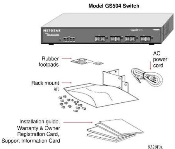
Model GS504 Switch NETGEAR Rubber footpads Rack mount kit Installation guide, Warranty & Owner Registration Card, Support Information Card 9328FAVerify that your package contains the following:
- Model GS504 switch
- Rubber footpads for tabletop installation
• This installation guide - Rack mount kit for 19-inch rack installation
• Warranty & Owner Registration Card
• Support Information Card - Power cord

Product Illustration
Front Panel
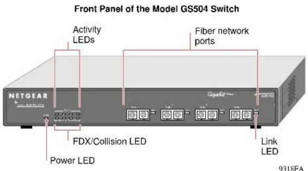
The front panel of the Model GS504 switch contains the following LEDs that correspond to each network port: Activity (Rx/Tx) and FDX (full-duplex)/Collision. Each fiber network port has its own Link LED (located to the right of each 1000 Mbps port).
text_image
Front Panel of the Model GS504 Switch Activity LEDs Fiber network ports NETGEAR Capacit Link LED FDX/Collision LED Power LED 9318FALEDs
The table below describes the activity of the LEDs.
| Label | Color Activity Description | ||
| Power | Green | OnOff | Power is supplied to the switch.Power is disconnected. |
| FDX/Col Green | Yellow | OnOffBlinking | The port is operating in full-duplex mode.The port is operating in half-duplex mode.Data collisions are occurring on the port. In a full-duplex environment, there is no collision. In a half-duplex environment, some collisions are normal. |
| Activity Green | Blinking P | Packet trans | mission or reception is occurring on the port. |
| Link | Green | OnOff | A valid 1000 Mbps link is established on the port.A link is not established on the port. |
Rear Panel
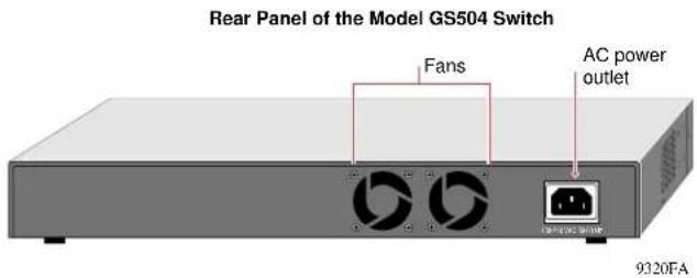
The rear panel of the Model GS504 switch has fans for cooling and a standard AC power receptacle for the supplied power cord.
text_image
Rear Panel of the Model GS504 Switch Fans AC power outlet 9320FA
Applications
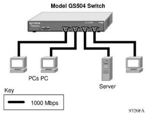
Desktop Switching
The Model GS504 switch is used as a desktop switch to build a powerful network that enables users to have 1000 Mbps access to a file server. If a full-duplex adapter card is installed in the server or PC, a 2000 Mbps connection will be provided to each server and PC.
flowchart
graph TD
    A["Model GS504 Switch"] --> B["PCs PC"]
    A --> C["Server"]
    A --> D["PCs PC"]
    B --> E["1000 Mbps"]
    C --> F["1000 Mbps"]
    D --> G["1000 Mbps"]
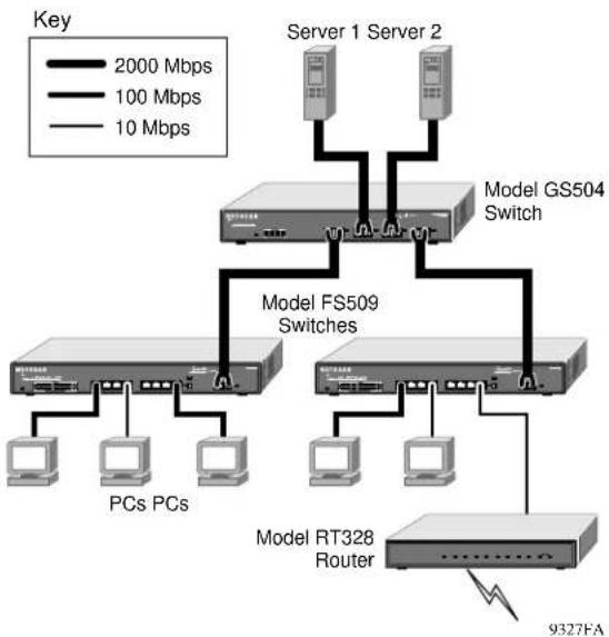
Segment Switching and Bridging from 10/100 Mbps to 1000 Mbps
The Model GS504, as illustrated below, connects multiple power workgroups and servers using high-speed gigabit fiber links. Each power workgroup is anchored by a NETGEAR FS509 switch. Because each fiber link can be up to 525 m long, these workgroups can be located on separate floors or in different buildings.
flowchart
graph TD
    A["Server 1 Server 2"] --> B["Model GS504 Switch"]
    C["Server 1 Server 2"] --> B
    B --> D["Model FS509 Switches"]
    D --> E["PCs PCs"]
    D --> F["Model RT328 Router"]
    G["9327FA"] --> H["Router"]
    style A fill:#f9f,stroke:#333
    style C fill:#f9f,stroke:#333
    style B fill:#ccf,stroke:#333
    style D fill:#ccf,stroke:#333
    style E fill:#ccf,stroke:#333
    style F fill:#ccf,stroke:#333
    style G fill:#dfd,stroke:#333

Prepare the Site
Before you begin installing your switch, prepare the installation site. Make sure your operating environment meets the operating environment requirements of the equipment.
| Characteristic | Requirement |
| Temperature | Ambient temperature between 0° and 40°C (32° and 104°F).No nearby heat sources such as direct sunlight, warm air exhausts, or heaters. |
| Operating humidity | Maximum relative humidity of 90%, noncondensing. |
| Ventilation Minimum 2 | nches (5.08 cm) on all sides for cooling.Adequate airflow in room or wiring closet. |
| Operating conditions At least 6 feet (1.83 m) to nearest source of electromagnetic noise (such as photocopy machine or arc welder). | |
| Power Adequate power | source within 6 feet (1.83 m). |

Installation
Installation on a Flat Surface
To install the switch on a flat surface, be sure to attach the rubber footpads to the bottom of the switch.
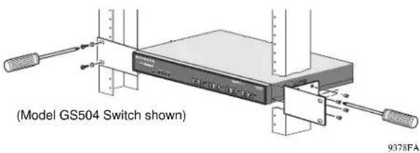
Installation in a Rack
Refer to the following illustration when installing the switch in a rack.
text_image
(Model GS504 Switch shown) 9378FA
Connecting Devices to the Switch
To connect the switch:
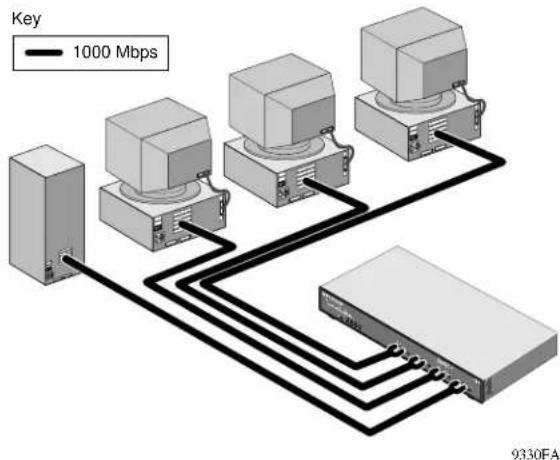
- Connect the devices to the network ports on the switch, using 50 m or 62.5 m multimode fiber cables with SC plugs.

Note: Ethernet specifications limit the cable length between your PC or server and the switch to 525 m for 50 ∝m and 260 m for 62.5 ∝m fiber.
- Connect one end of the DC power adapter cable to the power outlet on the rear panel of the switch and the other end of the power adapter cable to the wall outlet.
Refer to the following illustration when connecting the switch.
flowchart
graph TD
    A["Device 1"] --> B["Device 2"]
    B --> C["Device 3"]
    C --> D["Device 4"]
    D --> E["Device 5"]
    E --> F["Device 6"]
    F --> G["Device 7"]
    G --> H["Device 8"]
    H --> I["Device 9"]
    I --> J["Device 10"]
    style A fill:#f9f,stroke:#333
    style B fill:#f9f,stroke:#333
    style C fill:#f9f,stroke:#333
    style D fill:#f9f,stroke:#333
    style E fill:#f9f,stroke:#333
    style F fill:#f9f,stroke:#333
    style G fill:#f9f,stroke:#333
    style H fill:#f9f,stroke:#333
    style I fill:#f9f,stroke:#333
    style J fill:#f9f,stroke:#333
Model GS504 4-Port Gigabit Switch Installation Guide
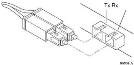
Using the SC Connector
The duplex SC connector connects stations, hubs, and switches that support the 1000BASE-SX fiber interface. Each fiber link needs a clearly defined, external crossover. In other words, the transmit port of one interface must be wired to the receive port of the opposite interface and vice versa. Fiber cables must be connected in this manner to transmit and receive data.
text_image
Tx Rx 8895FA
Verify Installation
When power has been applied to the switch, verify that:
- The green Pwr LED on the front panel is on.
- The green Link LED on each connected port is on.
When the switch is connected and operating, refer to the table in “LEDs” for information about the LEDs and their activity.
Troubleshooting Information
| Symptom | Cause Solution | |
| Power LED is off. | No power is received at the hub. | Check the power cord connections for the switch and the connected device.Make sure all cables used are correct and comply with Ethernet specifications. |
| Link LED is off or intermittent. | Port connection is not functioning. | Check the crimp on the fiber connectors and make sure that the plug is properly inserted and locked into the port at both the switch and the connecting device.Make sure all cables used are correct and comply with Ethernet specifications.Check for a defective adapter card, cable, or port by testing them in an alternate environment where all products are functioning. |
| File transfer is slow or performance degradation is a problem. | Half- or full-duplex setting on the NETGEAR switch and the connected device are not the same. | Make sure the remote link partner is set to autonegotiate or forced to full-duplex operation. |
| A segment or device is not recognized as part of the network. | One or more devices are not properly connected, or cabling does not meet Ethernet guidelines. | Verify that the cabling is correct. Be sure all cable connectors are securely positioned in the required ports. Equipment may have been accidentally disconnected. |
| FDX/Col LED is blinking yellow excessively. | Collisions are occurring on the connected segment. | Some collisions are normal when the connection is operating in half-duplex mode. |
| Duplex modes are mismatched. | Recheck the link partner settings. | |
Technical Specifications
| General Specifications | Model GS504 Switch |
| Network Protocol and Standards Compatibility | IEEE 8023z 1000BASE-SX |
| Data Rate | 1000 Mbps with 8B/10B encoding |
| Interface | Duplex SC connector for 1000BASE-SX Gigabit Ethernet |
| Power Consumption | 25 W |
| Input Voltage (Power Adapter) | 100–240 V AC |
| Physical SpecificationsDimensions: 13.0 x 1.7 x 8.0 in.Weight: 5.3 lb; 2.3 kg | 33.0 x 4.3 x 20.7 cm |
| Environmental SpecificationsOperating temperature: 0Operating humidity: 90% maximum | ° to 40°C (32° to 104°F)relative humidity, noncondensing |
| Electromagnetic Compliance | CE mark, commercialFCC Part 15 Class AVCCI Class AEN 55022 (CISPR 22) Class A, EN50082-1C-Tick |
| Safety Agency Approvals | UL Listed (UL 1950), cULTUV Licensed (EN 60 950), IEC 95 |
| Performance SpecificationsFrame filter rate: 1,480,000 frames/second maximumFrame forward rate: 1,480,000 frames/second maximumNetwork latency (using 64-byte packets):Address database size: 8,000 media access control (MAC) addressesAddressing: 48-bit MAC addressQueue buffer: 2 MB memory per port |
© 2000 by NETGEAR, Inc. All rights reserved.
Trademarks
NETGEAR ^™ is a trademark of NETGEAR, Inc. Windows ^® is a registered trademark of Microsoft Corporation. Other brand and product names are trademarks or registered trademarks of their respective holders. Information is subject to change without notice. All rights reserved.
Statement of Conditions
In the interest of improving internal design, operational function, and/or reliability, NETGEAR reserves the right to make changes to the products described in this document without notice.
NETGEAR does not assume any liability that may occur due to the use or application of the product(s) or circuit layout(s) described herein.
Certificate of the Manufacturer/Importer
It is hereby certified that the NETGEAR Model GS504 Gigabit Switch has been suppressed in accordance with the conditions set out in the BMPT-AmtsblVfg 243/1991 and Vfg 46/1992. The operation of some equipment (for example, test transmitters) in accordance with the regulations may, however, be subject to certain restrictions. Please refer to the notes in the operating instructions.
Federal Office for Telecommunications Approvals has been notified of the placing of this equipment on the market and has been granted the right to test the series for compliance with the regulations.
Voluntary Control Council for Interference (VCCI) Statement
This equipment is in the first category (information equipment to be used in commercial and/or industrial areas) and conforms to the standards set by the Voluntary Control Council for Interference by Data Processing Equipment and Electronic Office Machines that are aimed at preventing radio interference in commercial and/or industrial areas.
Consequently, when this equipment is used in a residential area or in an adjacent area thereto, radio interference may be caused to equipment such as radios and TV receivers.
Federal Communications Commission (FCC) Compliance Notice: Radio Frequency Notice
This device complies with part 15 of the FCC Rules. Operation is subject to the following two conditions:
- This device may not cause harmful interference.
- This device must accept any interference received, including interference that may cause undesired operation.
Note: This equipment has been tested and found to comply with the limits for a Class A digital device, pursuant to part 15 of the FCC Rules. These limits are designed to provide reasonable protection against harmful interference in a residential installation. This equipment generates, uses, and can radiate radio frequency energy and, if not installed and used in accordance with the instructions, may cause harmful interference to radio communications. However, there is no guarantee that interference will not occur in a particular installation. If this equipment does cause harmful interference to radio or television reception, which can be determined by turning the equipment off and on, the user is encouraged to try to correct the interference by one or more of the following measures:
- Reorient or relocate the receiving antenna.
- Increase the separation between the equipment and receiver.
- Connect the equipment into an outlet on a circuit different from that to which the receiver is connected.
- Consult the dealer or an experienced radio/TV technician for help.
EN 55 022 Declaration of Conformance
This is to certify that the NETGEAR Model GS504 Gigabit Switch is shielded against the generation of radio interference in accordance with the application of Council Directive 89/336/EEC, Article 4a. Conformity is declared by the application of EN 55 022 Class A (CISPR 22).
Canadian Department of Communications Radio Interference Regulations
This digital apparatus (NETGEAR Model GS504 Gigabit Switch) does not exceed the Class A limits for radio-noise emissions from digital apparatus as set out in the Radio Interference Regulations of the Canadian Department of Communications.
4500 Great America Parkway
Santa Clara, CA 95054
USA
Phone: 1-888-NETGEAR
E-mail: support@NETGEAR.com
www.NETGEAR.com