
SP001GD201 - Cordless plunge saw MAKITA - Free user manual and instructions
Find the device manual for free SP001GD201 MAKITA in PDF.


| Brand | Makita |
| Model | SP001G (SP001GD201) |
| Product Type | Cordless Plunge Cut Saw |
| Blade Diameter | 165 mm |
| Max Cutting Depth at 0° | 56 mm |
| Max Cutting Depth at 45° | 40 mm |
| Max Cutting Depth at 48° | 38 mm |
| No Load Speed | 2,500 – 4,900 min⁻¹ (variable) |
| Number of Speed Settings | 5 |
| Overall Length (with BL4040) | 375 mm |
| Net Weight (without battery) | 4.4 – 5.0 kg (depending on battery) |
| Rated Voltage | DC 36 V – 40 V max |
| Compatible Battery Cartridges | BL4020, BL4025*, BL4040*, BL4050F* (*recommended) |
| Compatible Chargers | DC40RA, DC40RB, DC40RC |
| Bevel Capacity | 48° left, -1° left |
| Plunge Cutting | Yes |
| Electric Brake | Yes |
| Soft Start | Yes |
| Constant Speed Control | Yes (under load) |
| Dust Extraction | Yes (dust nozzle, compatible with Makita vacuum) |
| Wireless Activation | Yes (with optional wireless unit) |
| Guide Rail Compatible | Yes (optional accessory) |
| Sub Base (Guide Rule) | Optional accessory |
| Safety Features | Blade guard, lock-off button, shaft lock |
| Maintenance | Clean blade guard regularly; adjust 0° and 45° accuracy via adjusting bolts |
Frequently Asked Questions - SP001GD201 MAKITA
User questions about SP001GD201 MAKITA
0 question about this device. Answer the ones you know or ask your own.
Ask a new question about this device
Download the instructions for your Cordless plunge saw in PDF format for free! Find your manual SP001GD201 - MAKITA and take your electronic device back in hand. On this page are published all the documents necessary for the use of your device. SP001GD201 by MAKITA.
USER MANUAL SP001GD201 MAKITA
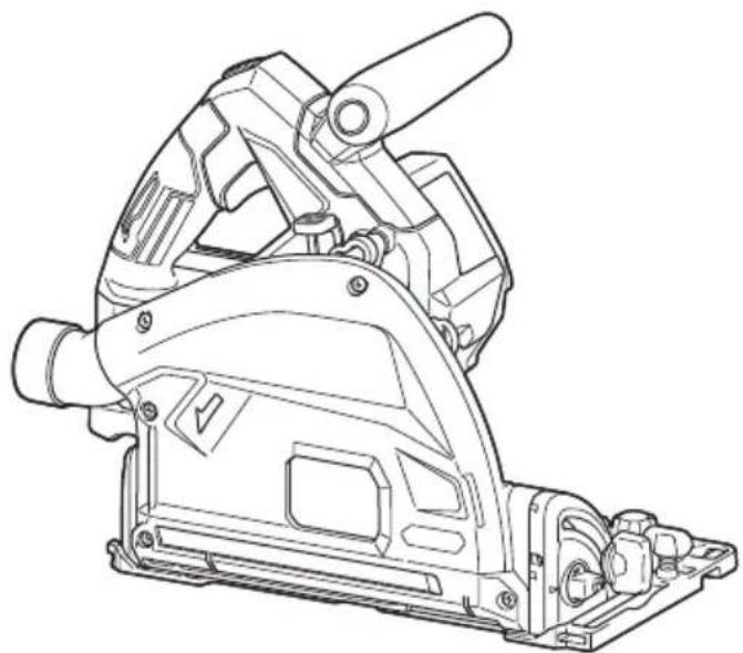
Cordless Plunge Cut Saw
SP001G
natural_image
Technical line drawing of a mechanical power saw assembly (no text or symbols)
Read before use.
SPECIFICATIONS
| Model: SP001G | ||
| Blade diameter 165 mm | ||
| Max. Cutting depth at 0° 56 mm | ||
| at 45° bevel 40 mm | ||
| at 48° bevel 38 mm | ||
| No load speed 2,500 - 4,900 min | -1 | |
| Overall length (with BL4040) 375 mm | ||
| Rated voltage D.C. 36 V - 40 V max | ||
| Net weight 4.4 - 5.0 kg | ||
• Due to our continuing program of research and development, the specifications herein are subject to change without notice.
- Specifications and battery cartridge may differ from country to country.
- The weight may differ depending on the attachment(s), including the battery cartridge. The lightest and heaviest combinations, according to EPTA-Procedure 01/2014, are shown in the table.
Applicable battery cartridge and charger
| Battery cartridge BL4020/BL4025*/BL4040*/BL4050F* | *: Recommended battery |
| Charger DC40RA / DC40RB / DC40RC |
• Some of the battery cartridges and chargers listed above may not be available depending on your region of residence.
⚠ WARNING: Only use the battery cartridges and chargers listed above. Use of any other battery cartridges and chargers may cause injury and/or fire.
Symbols
The followings show the symbols which may be used for the equipment. Be sure that you understand their meaning before use.

Read instruction manual.

Wear safety glasses.

Only for EU countries
Due to the presence of hazardous components in the equipment, waste electrical and electronic equipment, accumulators and batteries may have a negative impact on the environment and human health. Do not dispose of electrical and electronic appliances or batteries with household waste!
In accordance with the European Directive on waste electrical and electronic equipment and on accumulators and batteries and waste accumulators and batteries, as well as their adaptation to national law, waste electrical equipment, batteries and accumulators should be stored separately and delivered to a separate collection point for municipal waste, operating in accordance with the regulations on environmental protection.
This is indicated by the symbol of the crossed-out wheeled bin placed on the equipment.
Intended use
The tool is specially intended for performing plunge cuts. The tool is also intended for rip and cross cuts in wood. If the tool is equipped with proper circular saw blade, the tool can be used for sawing aluminum, plastic, mineral contained plastic, and similar materials.
Noise
The typical A-weighted noise level determined according to EN62841-2-5:
Sound pressure level (LpA) : 89 dB(A)
Sound power level ( LWA ): 100 dB (A)
Uncertainty (K) : 3 dB(A)
NOTE: The declared noise emission value(s) has been measured in accordance with a standard test method and may be used for comparing one tool with another.
NOTE: The declared noise emission value(s) may also be used in a preliminary assessment of exposure.
WARNING: Wear ear protection.
WARNING: The noise emission during actual use of the power tool can differ from the declared value(s) depending on the ways in which the tool is used especially what kind of workpiece is processed.
WARNING: Be sure to identify safety measures to protect the operator that are based on an estimation of exposure in the actual conditions of use (taking account of all parts of the operating cycle such as the times when the tool is switched off and when it is running idle in addition to the trigger time).
Vibration
The vibration total value (tri-axial vector sum) determined according to EN62841-2-5: Work mode: cutting wood Vibration emission ( ah,W ): 2.5 m/s 2 or less Uncertainty (K): 1.5 m/s 2 Work mode: cutting metal Vibration emission ( ah,M ): 2.5 m/s 2 or less Uncertainty (K): 1.5 m/s 2
NOTE: The declared vibration total value(s) has been measured in accordance with a standard test method and may be used for comparing one tool with another.
NOTE: The declared vibration total value(s) may also be used in a preliminary assessment of exposure.
⚠ WARNING: The vibration emission during actual use of the power tool can differ from the declared value(s) depending on the ways in which the tool is used especially what kind of workpiece is processed.
⚠ WARNING: Be sure to identify safety measures to protect the operator that are based on an estimation of exposure in the actual conditions of use (taking account of all parts of the operating cycle such as the times when the tool is switched off and when it is running idle in addition to the trigger time).
EC Declaration of Conformity
For European countries only
The EC declaration of conformity is included as Annex A to this instruction manual.
SAFETY WARNINGS
General power tool safety warnings
WARNING: Read all safety warnings, instructions, illustrations and specifications provided with this power tool. Failure to follow all instructions listed below may result in electric shock, fire and/or serious injury.
Save all warnings and instructions for future reference.
The term "power tool" in the warnings refers to your mains-operated (corded) power tool or battery-operated (cordless) power tool.
Work area safety
- Keep work area clean and well lit. Cluttered or dark areas invite accidents.
- Do not operate power tools in explosive atmospheres, such as in the presence of flammable liquids, gases or dust. Power tools create sparks which may ignite the dust or fumes.
- Keep children and bystanders away while operating a power tool. Distractions can cause you to lose control.
Electrical safety
- Power tool plugs must match the outlet. Never modify the plug in any way. Do not use any adapter plugs with earthed (grounded) power tools. Unmodified plugs and matching outlets will reduce risk of electric shock.
- Avoid body contact with earthed or grounded surfaces, such as pipes, radiators, ranges and refrigerators. There is an increased risk of electric shock if your body is earthed or grounded.
- Do not expose power tools to rain or wet conditions. Water entering a power tool will increase the risk of electric shock.
- Do not abuse the cord. Never use the cord for carrying, pulling or unplugging the power tool. Keep cord away from heat, oil, sharp edges or moving parts. Damaged or entangled cords increase the risk of electric shock.
- When operating a power tool outdoors, use an extension cord suitable for outdoor use. Use of a cord suitable for outdoor use reduces the risk of electric shock.
- If operating a power tool in a damp location is unavoidable, use a residual current device (RCD) protected supply. Use of an RCD reduces the risk of electric shock.
- Power tools can produce electromagnetic fields (EMF) that are not harmful to the user. However, users of pacemakers and other similar medical devices should contact the maker of their device and/or doctor for advice before operating this power tool.
Personal safety
- Stay alert, watch what you are doing and use common sense when operating a power tool. Do not use a power tool while you are tired or under the influence of drugs, alcohol or medication. A moment of inattention while operating power tools may result in serious personal injury.
- Use personal protective equipment. Always wear eye protection. Protective equipment such as a dust mask, non-skid safety shoes, hard hat or hearing protection used for appropriate conditions will reduce personal injuries.
- Prevent unintentional starting. Ensure the switch is in the off-position before connecting to power source and/or battery pack, picking up or carrying the tool. Carrying power tools with your finger on the switch or energising power tools that have the switch on invites accidents.
- Remove any adjusting key or wrench before turning the power tool on. A wrench or a key left attached to a rotating part of the power tool may result in personal injury.
- Do not overreach. Keep proper footing and balance at all times. This enables better control of the power tool in unexpected situations.
- Dress properly. Do not wear loose clothing or jewellery. Keep your hair and clothing away from moving parts. Loose clothes, jewellery or long hair can be caught in moving parts.
-
If devices are provided for the connection of dust extraction and collection facilities, ensure these are connected and properly used. Use of dust collection can reduce dust-related hazards.
-
Do not let familiarity gained from frequent use of tools allow you to become complacent and ignore tool safety principles. A careless action can cause severe injury within a fraction of a second.
- Always wear protective goggles to protect your eyes from injury when using power tools. The goggles must comply with ANSI Z87.1 in the USA, EN 166 in Europe, or AS/NZS 1336 in Australia/New Zealand. In Australia/New Zealand, it is legally required to wear a face shield to protect your face, too.

natural_image
Line drawing of a person wearing a helmet and safety goggles (no text or symbols)It is an employer's responsibility to enforce the use of appropriate safety protective equipments by the tool operators and by other persons in the immediate working area.
Power tool use and care
- Do not force the power tool. Use the correct power tool for your application. The correct power tool will do the job better and safer at the rate for which it was designed.
- Do not use the power tool if the switch does not turn it on and off. Any power tool that cannot be controlled with the switch is dangerous and must be repaired.
- Disconnect the plug from the power source and/or remove the battery pack, if detachable, from the power tool before making any adjustments, changing accessories, or storing power tools. Such preventive safety measures reduce the risk of starting the power tool accidentally.
- Store idle power tools out of the reach of children and do not allow persons unfamiliar with the power tool or these instructions to operate the power tool. Power tools are dangerous in the hands of untrained users.
- Maintain power tools and accessories. Check for misalignment or binding of moving parts, breakage of parts and any other condition that may affect the power tool's operation. If damaged, have the power tool repaired before use. Many accidents are caused by poorly maintained power tools.
- Keep cutting tools sharp and clean. Properly maintained cutting tools with sharp cutting edges are less likely to bind and are easier to control.
-
Use the power tool, accessories and tool bits etc. in accordance with these instructions, taking into account the working conditions and the work to be performed. Use of the power tool for operations different from those intended could result in a hazardous situation.
-
Keep handles and grasping surfaces dry, clean and free from oil and grease. Slippery handles and grasping surfaces do not allow for safe handling and control of the tool in unexpected situations.
- When using the tool, do not wear cloth work gloves which may be entangled. The entanglement of cloth work gloves in the moving parts may result in personal injury.
Battery tool use and care
- Recharge only with the charger specified by the manufacturer. A charger that is suitable for one type of battery pack may create a risk of fire when used with another battery pack.
- Use power tools only with specifically designated battery packs. Use of any other battery packs may create a risk of injury and fire.
- When battery pack is not in use, keep it away from other metal objects, like paper clips, coins, keys, nails, screws or other small metal objects, that can make a connection from one terminal to another. Shorting the battery terminals together may cause burns or a fire.
- Under abusive conditions, liquid may be ejected from the battery; avoid contact. If contact accidentally occurs, flush with water. If liquid contacts eyes, additionally seek medical help. Liquid ejected from the battery may cause irritation or burns.
- Do not use a battery pack or tool that is damaged or modified. Damaged or modified batteries may exhibit unpredictable behaviour resulting in fire, explosion or risk of injury.
- Do not expose a battery pack or tool to fire or excessive temperature. Exposure to fire or temperature above 130 °C may cause explosion.
- Follow all charging instructions and do not charge the battery pack or tool outside the temperature range specified in the instructions. Charging improperly or at temperatures outside the specified range may damage the battery and increase the risk of fire.
Service
- Have your power tool serviced by a qualified repair person using only identical replacement parts. This will ensure that the safety of the power tool is maintained.
- Never service damaged battery packs. Service of battery packs should only be performed by the manufacturer or authorized service providers.
- Follow instruction for lubricating and changing accessories.
Cordless circular saw safety warnings
Cutting procedures
- ADANGER: Keep hands away from cutting area and the blade. Keep your second hand on auxiliary handle, or motor housing. If both hands are holding the saw, they cannot be cut by the blade.
-
Do not reach underneath the workpiece. The guard cannot protect you from the blade below the workpiece.
-
Adjust the cutting depth to the thickness of the workpiece. Less than a full tooth of the blade teeth should be visible below the workpiece.
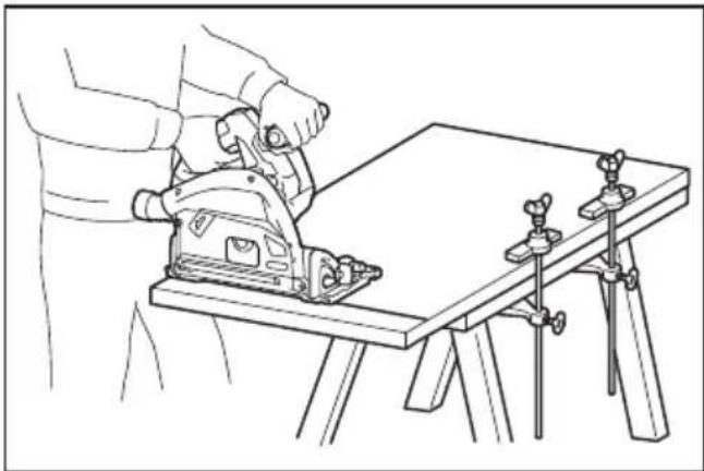
- Never hold the workpiece in your hands or across your leg while cutting. Secure the workpiece to a stable platform. It is important to support the work properly to minimise body exposure, blade binding, or loss of control.
natural_image
Line drawing of a person using a power tool on a workbench with clamps (no text or symbols)- Hold the power tool by insulated gripping surfaces, when performing an operation where the cutting tool may contact hidden wiring.
Contact with a "live" wire will also make exposed metal parts of the power tool "live" and could give the operator an electric shock.
-
When ripping, always use a rip fence or straight edge guide. This improves the accuracy of cut and reduces the chance of blade binding.
-
Always use blades with correct size and shape (diamond versus round) of arbour holes.
Blades that do not match the mounting hardware of the saw will run off-centre, causing loss of control.
- Never use damaged or incorrect blade washers or bolt. The blade washers and bolt were specially designed for your saw, for optimum performance and safety of operation.
Kickback causes and related warnings
— kickback is a sudden reaction to a pinched, jammed or misaligned saw blade, causing an uncontrolled saw to lift up and out of the workpiece toward the operator;
— when the blade is pinched or jammed tightly by the kerf closing down, the blade stalls and the motor reaction drives the unit rapidly back toward the operator;
— if the blade becomes twisted or misaligned in the cut, the teeth at the back edge of the blade can dig into the top surface of the wood causing the blade to climb out of the kerf and jump back toward the operator.
Kickback is the result of saw misuse and/or incorrect operating procedures or conditions and can be avoided by taking proper precautions as given below.
-
Maintain a firm grip with both hands on the saw and position your arms to resist kickback forces. Position your body to either side of the blade, but not in line with the blade. Kickback could cause the saw to jump backwards, but kickback forces can be controlled by the operator, if proper precautions are taken.
-
When blade is binding, or when interrupting a cut for any reason, release the trigger and hold the saw motionless in the material until the blade comes to a complete stop. Never attempt to remove the saw from the work or pull the saw backward while the blade is in motion or kickback may occur. Investigate and take corrective actions to eliminate the cause of blade binding.
- When restarting a saw in the workpiece, centre the saw blade in the kerf so that the saw teeth are not engaged into the material. If a saw blade binds, it may walk up or kickback from the workpiece as the saw is restarted.
- Support large panels to minimise the risk of blade pinching and kickback. Large panels tend to sag under their own weight. Supports must be placed under the panel on both sides, near the line of cut and near the edge of the panel.

natural_image
Line drawing of a mechanical device mounted on a flat table (no text or symbols)
natural_image
Diagram showing a device inside a table with a prohibition symbol (no text or labels)- Do not use dull or damaged blades.
Unsharpened or improperly set blades produce narrow kerf causing excessive friction, blade binding and kickback.
- Blade depth and bevel adjusting locking levers must be tight and secure before making the cut. If blade adjustment shifts while cutting, it may cause binding and kickback.
- Use extra caution when sawing into existing walls or other blind areas. The protruding blade may cut objects that can cause kickback.
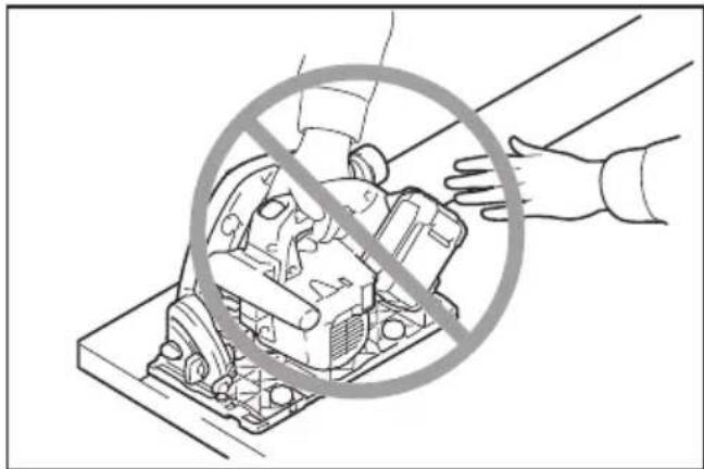
- ALWAYS hold the tool firmly with both hands. NEVER place your hand, leg or any part of your body under the tool base or behind the saw, especially when making cross-cuts. If kickback occurs, the saw could easily jump backwards over your hand, leading to serious personal injury.
natural_image
Illustration of a hand using a prohibition symbol to clean machinery (no text or symbols present)- Never force the saw. Push the saw forward at a speed so that the blade cuts without slowing. Forcing the saw can cause uneven cuts, loss of accuracy, and possible kickback.
Guard function
- Check the guard for proper closing before each use. Do not operate the saw if the guard does not move freely and enclose the blade instantly. Never clamp or tie the guard so that the blade is exposed. If the saw is accidentally dropped, the guard may be bent. Check to make sure that the guard moves freely and does not touch the blade or any other part, in all angles and depths of cut.
- Check the operation and condition of the guard return spring. If the guard and the spring are not operating properly, they must be serviced before use. The guard may operate sluggishly due to damaged parts, gummy deposits, or a build-up of debris.
- Assure that the base plate of the saw will not shift while performing a "plunge cut". Blade shifting sideways will cause binding and likely kick back.
- Always observe that the guard is covering the blade before placing the saw down on bench or floor. An unprotected, coasting blade will cause the saw to walk backwards, cutting whatever is in its path. Be aware of the time it takes for the blade to stop after the switch is released.
Additional safety warnings
- Use extra caution when cutting damp wood, pressure treated lumber, or wood containing knots. Maintain smooth advancement of tool without decrease in blade speed to avoid overheating the blade tips and if cutting plastics, to avoid melting the plastic.
- Do not attempt to remove cut material when blade is moving. Wait until blade stops before grasping cut material. Blades coast after turn off.
- Avoid cutting nails. Inspect for and remove all nails from lumber before cutting.
- Place the wider portion of the saw base on that part of the workpiece which is solidly supported, not on the section that will fall off when the cut is made. If the workpiece is short or small, clamp it down. DO NOT TRY TO HOLD SHORT PIECES BY HAND!

natural_image
Technical illustration of a mechanical assembly with a hand holding a tool, no text or symbols present- Before setting the tool down after completing a cut, be sure that the guard has closed and the blade has come to a complete stop.
- Never attempt to saw with the circular saw held upside down in a vise. This is extremely dangerous and can lead to serious accidents.

natural_image
Line drawing of a hand holding a wooden board with a diagonal line and a circular overlay showing a crossed-out gear (no text or symbols)- Some material contains chemicals which may be toxic. Take caution to prevent dust inhalation and skin contact. Follow material supplier safety data.
- Do not stop the blades by lateral pressure on the saw blade.
- Do not use any abrasive wheels.
- Only use the saw blade with the diameter that is marked on the tool or specified in the manual. Use of an incorrectly sized blade may affect the proper guarding of the blade or guard operation which could result in serious personal injury.
- Keep blade sharp and clean. Gum and wood pitch hardened on blades slows saw and increases potential for kickback. Keep blade clean by first removing it from tool, then cleaning it with gum and pitch remover, hot water or kerosene. Never use gasoline.
- Wear a dust mask and hearing protection when use the tool.
- Always use the saw blade intended for cutting the material that you are going to cut.
- Only use the saw blades that are marked with a speed equal or higher than the speed marked on the tool.
- (For European countries only) Always use the blade which conforms to EN847-1.
SAVE THESE INSTRUCTIONS.
WARNING: DO NOT let comfort or familiarity with product (gained from repeated use) replace strict adherence to safety rules for the subject product. MISUSE or failure to follow the safety rules stated in this instruction manual may cause serious personal injury.
Important safety instructions for battery cartridge
- Before using battery cartridge, read all instructions and cautionary markings on (1) battery charger, (2) battery, and (3) product using battery.
- Do not disassemble or tamper the battery cartridge. It may result in a fire, excessive heat, or explosion.
- If operating time has become excessively shorter, stop operating immediately. It may result in a risk of overheating, possible burns and even an explosion.
- If electrolyte gets into your eyes, rinse them out with clear water and seek medical attention right away. It may result in loss of your eyesight.
- Do not short the battery cartridge:
(1) Do not touch the terminals with any conductive material.
(2) Avoid storing battery cartridge in a container with other metal objects such as nails, coins, etc.
(3) Do not expose battery cartridge to water or rain.
A battery short can cause a large current flow, overheating, possible burns and even a breakdown. - Do not store and use the tool and battery cartridge in locations where the temperature may reach or exceed 50 °C (122 °F).
- Do not incinerate the battery cartridge even if it is severely damaged or is completely worn out. The battery cartridge can explode in a fire.
- Do not nail, cut, crush, throw, drop the battery cartridge, or hit against a hard object to the battery cartridge. Such conduct may result in a fire, excessive heat, or explosion.
- Do not use a damaged battery.
- The contained lithium-ion batteries are subject to the Dangerous Goods Legislation requirements.
For commercial transports e.g. by third parties, forwarding agents, special requirement on packaging and labeling must be observed. For preparation of the item being shipped, consulting an expert for hazardous material is required. Please also observe possibly more detailed national regulations. Tape or mask off open contacts and pack up the battery in such a manner that it cannot move around in the packaging. -
When disposing the battery cartridge, remove it from the tool and dispose of it in a safe place. Follow your local regulations relating to disposal of battery.
-
Use the batteries only with the products specified by Makita. Installing the batteries to non-compliant products may result in a fire, excessive heat, explosion, or leak of electrolyte.
-
If the tool is not used for a long period of time, the battery must be removed from the tool.
-
During and after use, the battery cartridge may take on heat which can cause burns or low temperature burns. Pay attention to the handling of hot battery cartridges.
-
Do not touch the terminal of the tool immediately after use as it may get hot enough to cause burns.
-
Do not allow chips, dust, or soil stuck into the terminals, holes, and grooves of the battery cartridge. It may result in poor performance or breakdown of the tool or battery cartridge.
-
Unless the tool supports the use near high-voltage electrical power lines, do not use the battery cartridge near a high-voltage electrical power lines. It may result in a malfunction or breakdown of the tool or battery cartridge.
-
Keep the battery away from children.
SAVE THESE INSTRUCTIONS.
CAUTION: Only use genuine Makita batteries. Use of non-genuine Makita batteries, or batteries that have been altered, may result in the battery bursting causing fires, personal injury and damage. It will also void the Makita warranty for the Makita tool and charger.
Tips for maintaining maximum battery life
- Charge the battery cartridge before completely discharged. Always stop tool operation and charge the battery cartridge when you notice less tool power.
- Never recharge a fully charged battery cartridge. Overcharging shortens the battery service life.
- Charge the battery cartridge with room temperature at 10\ °C - 40\ °C ( 50\ °F - 104\ °F ). Let a hot battery cartridge cool down before charging it.
- When not using the battery cartridge, remove it from the tool or the charger.
- Charge the battery cartridge if you do not use it for a long period (more than six months).
Important safety instructions for wireless unit
- Do not disassemble or tamper with the wireless unit.
- Keep the wireless unit away from young children. If accidentally swallowed, seek medical attention immediately.
- Use the wireless unit only with Makita tools.
- Do not expose the wireless unit to rain or wet conditions.
-
Do not use the wireless unit in places where the temperature exceeds 50\ °C ( 122\ °F ).
-
Do not operate the wireless unit in places where medical instruments, such as heart pace makers are nearby.
- Do not operate the wireless unit in places where automated devices are nearby. If operated, automated devices may develop malfunction or error.
- Do not operate the wireless unit in places under high temperature or places where static electricity or electrical noise could be generated.
- The wireless unit can produce electromagnetic fields (EMF) but they are not harmful to the user.
- The wireless unit is an accurate instrument. Be careful not to drop or strike the wireless unit.
- Avoid touching the terminal of the wireless unit with bare hands or metallic materials.
- Always remove the battery on the product when installing the wireless unit into it.
- When opening the lid of the slot, avoid the place where dust and water may come into the slot. Always keep the inlet of the slot clean.
- Always insert the wireless unit in the correct direction.
- Do not press the wireless activation button on the wireless unit too hard and/or press the button with an object with a sharp edge.
- Always close the lid of the slot when operating.
- Do not remove the wireless unit from the slot while the power is being supplied to the tool. Doing so may cause a malfunction of the wireless unit.
- Do not remove the sticker on the wireless unit.
- Do not put any sticker on the wireless unit.
- Do not leave the wireless unit in a place where static electricity or electrical noise could be generated.
- Do not leave the wireless unit in a place subject to high heat, such as a car sitting in the sun.
- Do not leave the wireless unit in a dusty or powdery place or in a place corrosive gas could be generated.
- Sudden change of the temperature may bedew the wireless unit. Do not use the wireless unit until the dew is completely dried.
- When cleaning the wireless unit, gently wipe with a dry soft cloth. Do not use benzine, thinner, conductive grease or the like.
- When storing the wireless unit, keep it in the supplied case or a static-free container.
- Do not insert any devices other than Makita wireless unit into the slot on the tool.
- Do not use the tool with the lid of the slot damaged. Water, dust, and dirt come into the slot may cause malfunction.
- Do not pull and/or twist the lid of the slot more than necessary. Restore the lid if it comes off from the tool.
- Replace the lid of the slot if it is lost or damaged.
SAVE THESE INSTRUCTIONS.
FUNCTIONAL DESCRIPTION
CAUTION: Always be sure that the tool is switched off and the battery cartridge is removed before adjusting or checking function on the tool.
Installing or removing battery cartridge
CAUTION: Always switch off the tool before installing or removing of the battery cartridge.
CAUTION: Hold the tool and the battery cartridge firmly when installing or removing battery cartridge. Failure to hold the tool and the battery cartridge firmly may cause them to slip off your hands and result in damage to the tool and battery cartridge and a personal injury.
⚠️ CAUTION: Always install the battery cartridge fully until the red indicator cannot be seen. If not, it may accidentally fall out of the tool, causing injury to you or someone around you.
CAUTION: Do not install the battery cartridge forcibly. If the cartridge does not slide in easily, it is not being inserted correctly.

▶ 1. Red indicator 2. Button 3. Battery cartridge
To remove the battery cartridge, slide it from the tool while sliding the button on the front of the cartridge.
To install the battery cartridge, align the tongue on the battery cartridge with the groove in the housing and slip it into place. Insert it all the way until it locks in place with a little click. If you can see the red indicator as shown in the figure, it is not locked completely.
Tool / battery protection system
The tool is equipped with a tool/battery protection system. This system automatically cuts off power to the motor to extend tool and battery life. The tool will automatically stop during operation if the tool or battery is placed under one of the following conditions.
Overload protection
When the tool/battery is operated in a manner that causes it to draw an abnormally high current, the tool automatically stops. In this situation, turn the tool off and stop the application that caused the tool to become overloaded. Then turn the tool on to restart.
Overheat protection
When the tool/battery is overheated, the tool stops automatically. In this situation, let the tool cool down before turning the tool on again.
Overdischarge protection
When the battery capacity becomes low, the tool stops automatically. If the product does not operate even when the switches are operated, remove the batteries from the tool and charge the batteries.
Indicating the remaining battery capacity
Press the check button on the battery cartridge to indicate the remaining battery capacity. The indicator lamps light up for a few seconds.
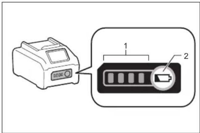
▶ 1. Indicator lamps 2. Check button
| Indicator lamps Remaining | capacity | ||
| Lighted Off | Blinking | ||
| 75% to 100% | |||
| 50% to 75% | |||
| 25% to 50% | |||
| 0% to 25% | |||
| Charge the battery. | |||
| The battery may have malfunctioned. | |||
NOTE: Depending on the conditions of use and the ambient temperature, the indication may differ slightly from the actual capacity.
NOTE: The first (far left) indicator lamp will blink when the battery protection system works.
Adjusting depth of cut
⚠️ CAUTION: After adjusting the depth of cut, always tighten the clamping screw securely.
Loosen the clamping screw on the depth guide and move the blade lower limit stopper to the desired depth on the scale plate. At the desired depth of cut, tighten the clamping screw firmly.
For cleaner, safer cuts, set cut depth so that no more than one blade tooth projects below workpiece. Using proper cut depth helps to reduce potential for dangerous KICKBACKS which can cause personal injury.

▶ 1. Blade lower limit stopper 2. Clamping screw
Quick stop button for 2 to 3 mm depth of cut when using guide rail (optional accessory)
This tool has the quick stop button for 2 to 3 mm depth of cut on the gear housing aside the rear handle when using guide rail. This is used when avoiding splinter on the workpiece in the cut. Make a pass of the 2 to 3 mm first cut and then make another pass of usual cut.
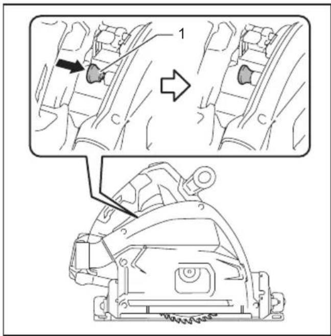
▶ 1. Quick stop button
To obtain the 2 to 3 mm depth of cut, push in the quick stop button toward the saw blade. This is convenient for avoiding splinter on the workpiece.
To release the depth of cut from this position for free depth of cut, just pull the button back.
Bevel cutting
Loosen the clamping screws. Set for the desired angle by tilting accordingly, then tighten the clamping screws securely.

▶ 1. Clamping screw 2. Bevel scale plate
You can set the sub base facing up as illustrated to prevent the tool from falling down while bevel cutting.

natural_image
Technical line drawing of a mechanical assembly with an inset showing a detail (no text or symbols)▶ 1. Sub base (Optional accessory)
Positive stopper
The positive stopper is useful for setting the designated angle quickly. Turn the positive stopper so that the arrow on it points 22.5°. Loosen the clamping screws in front and back. Then tilt the blade until it stops and secure the base with the clamping screws.

▶ 1. Positive stopper 2. Clamping screw
48°-bevel cutting
To perform 48irc -bevel cutting, loosen the clamping screws and fully tilt the lever toward the direction of the arrow in the figure. Then set the bevel angle to 48irc and tighten the clamping screws.
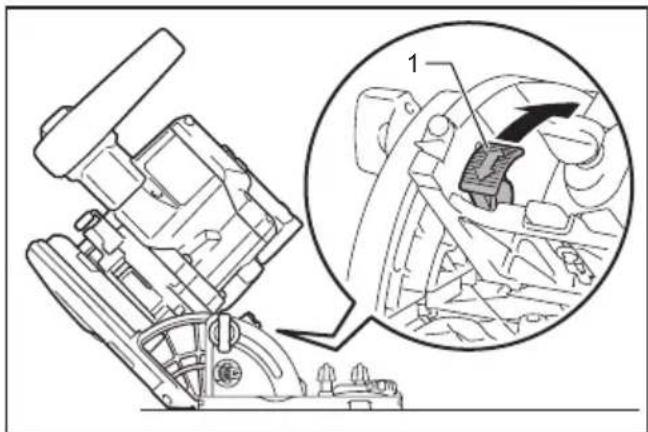
natural_image
Technical line drawing of a mechanical assembly with an inset showing a close-up view of a component (no text or symbols present)- Lever
-1°-bevel cutting
To perform -1irc -bevel cutting, loosen the clamping screws and press the levers toward the direction of the arrow in the figure. Then set the bevel angle to -1irc and tighten the clamping screws.

▶ 1. Lever
Sighting

- Base
The cutting line varies depending on the cutting angle and whether you use the guide rail (optional accessory).
When using the tool without guide rail
For straight cuts, align the A position on the front of the base with your cutting line. For 45° bevel cuts, align the B position with it.
When using the tool with guide rail
For both straight cuts and 45irc bevel cuts, always align the A position on the front of the base with your cutting line.
Switch action
WARNING: Before installing the battery cartridge into the tool, always check to see that the switch trigger actuates properly and returns to the "OFF" position when released.
WARNING: NEVER defeat the lock-off button by taping down or some other means. A switch with a negated lock-off button may result in unintentional operation and serious personal injury.
WARNING: NEVER use the tool if it runs when you simply pull the switch trigger without pressing the lock-off button. A switch in need of repair may result in unintentional operation and serious personal injury. Return tool to a Makita service center for proper repairs BEFORE further usage.
To prevent the switch trigger from being accidentally pulled, a lock-off button is provided. To start the tool, depress the lock-off button and pull the switch trigger. Release the switch trigger to stop.
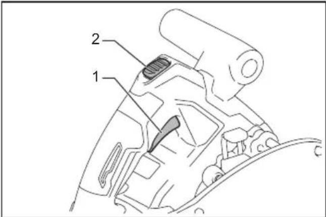
▶ 1. Switch trigger 2. Lock-off button
NOTICE: Do not pull the switch trigger hard without pressing in the lock-off button. This can cause switch breakage.
Speed adjusting dial
The tool speed can be adjusted by turning the speed adjusting dial. The speed of the blade rotation increases as you increase the number on the speed adjusting dial.

▶ 1. Speed adjusting dial
Refer to the table to select the proper speed for the workpiece to be cut. However, the appropriate speed may differ with the type or thickness of the workpiece. In general, higher speeds will allow you to cut workpieces faster but the service life of the blade will be reduced.
| Number Blade rotating speed per minute (min -1 ) | |
| 1 2,500 min | -1 |
| 2 3,000 min | -1 |
| 3 3,500 min | -1 |
| 4 4,000 min | -1 |
| 5 4,900 min | -1 |
CAUTION: The speed adjusting dial is not for using low speed rated saw blades but for obtaining a speed which is suitable to material of workpiece. Use only saw blades which are rated for at least the maximum no load speed stated in the SPECIFICATIONS.
NOTICE: The speed adjusting dial can be turned only as far as 5 and back to 1. Do not force it past 5 or 1, or the speed adjusting function may no longer work.
Electronic function
The tools equipped with electronic function are easy to operate because of the following features.
Constant speed control
Electronic speed control for obtaining constant speed. Possible to get fine finish, because the rotating speed is kept constant even under load condition.
Soft start feature
Soft start because of suppressed starting shock.
Electric brake
This tool is equipped with an electric blade brake. If the tool consistently fails to quickly stop the circular saw blade after switch lever release, have tool serviced at a Makita service center.
⚠CAUTION: The blade brake system is not a substitute for blade guard. NEVER USE TOOL WITHOUT A FUNCTIONING BLADE GUARD. SERIOUS PERSONAL INJURY CAN RESULT.
ASSEMBLY
⚠️CAUTION: Always be sure that the tool is switched off and the battery cartridge is removed before carrying out any work on the tool.
Hex wrench storage
When not in use, store the hex wrench as shown in the figure to keep it from being lost.

natural_image
Technical line drawing of a mechanical assembly with labeled component (1), no readable text or symbols present▶ 1. Hex wrench
Removing or installing circular saw blade
CAUTION: Be sure the circular saw blade is installed with teeth pointing up at the front of the tool.
CAUTION: Use only the Makita wrench to install or remove the circular saw blade.
To remove the circular saw blade:
- Depress the lock-off button and lower the handle a little. Turn the locking lever and lower the handle until the lock pin fits in the hole.

▶ 1. Lock-off button 2. Locking lever 3. Lock pin 4. Hole for lock pin
- Press the shaft lock fully so that the blade cannot revolve and use the hex wrench to loosen the hex bolt.

▶ 1. Shaft lock 2. Hex wrench 3. Tighten 4. Loosen
- Remove the hex bolt, outer flange, and circular saw blade.

▶ 1. Hex bolt 2. Outer flange 3. Inner flange
4. Circular saw blade
WARNING: If the inner flange is removed, be sure to install it on the spindle. When installing, choose a correct side on which protrusion fits into the saw blade hole perfectly. Mounting the blade on the wrong side can result in the dangerous vibration.
To install the circular saw blade, follow the removal procedure in reverse. Depress the lock-off button to release the lock pin from the hole.
WARNING: BE SURE TO TIGHTEN THE HEX BOLT SECURELY. Also be careful not to tighten the bolt forcibly. Slipping your hand from the hex wrench can cause a personal injury.
Blade guard cleaning
When changing the circular saw blade, make sure to also clean the blade guard of accumulated sawdust as discussed in the Maintenance section. Such efforts do not replace the need to check guard operation before each use.
Connecting a vacuum cleaner
Optional accessory
When you wish to perform clean cutting operation, connect a Makita vacuum cleaner to your tool. Connect a hose of the vacuum cleaner to the dust nozzle using the front cuff 24.
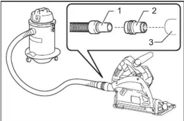
▶ 1. Hose of the vacuum cleaner 2. Front cuff 24
3. Dust nozzle
Adjusting angle of dust nozzle
The angle of the dust nozzle can be adjusted by rotating the dust nozzle.
When operating the tool without connecting a vacuum cleaner, bring the dust nozzle downward to prevent the operator from being exposed to sawdust.
When operating the tool with connecting a vacuum cleaner, bring the dust nozzle upward to keep the hose of the vacuum cleaner from getting caught in the workpiece or the guide rail.
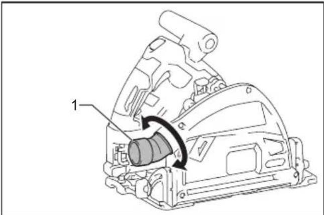
- Dust nozzle
OPERATION
This tool is intended to cut wood products. With appropriate Makita genuine circular saw blades, following materials can also be sawed:
• Aluminum products
- Plastic
• Mineral contained plastic
Refer to our website or contact your local Makita dealer for the correct circular saw blades to be used for the material to be cut.
⚠️CAUTION: When cutting plastic materials, avoid melting it by overheating of the blade tip.
⚠️CAUTION: Be sure to move the tool forward in a straight line gently. Forcing or twisting the tool will result in overheating the motor and dangerous kickback, possibly causing severe injury.
⚠CAUTION: Never approach any part of your body under the tool base when section cutting, especially at starting. Doing so may cause serious personal injuries. The blade is exposed under the tool base.
⚠️CAUTION: Wear dust mask when performing cutting operation.
NOTE: When the battery cartridge temperature is low, the tool may not work to its full capacity. At this time, for example, use the tool for a light-duty cut for a while until the battery cartridge warms up as high as room temperature. Then, the tool can work to its full capacity.
Section cutting (ordinary sawing)

natural_image
Line drawing of a person using a power tool on a workbench (no text or symbols)Hold the tool firmly. The tool is provided with both a front grip and rear handle. Use both to best grasp the tool. If both hands are holding saw, they cannot be cut by the circular saw blade. Set the base on the workpiece to be cut without the circular saw blade making any contact. Then push in the lock-off button and pull the switch trigger. Wait until the circular saw blade attains full speed. Now press down the saw head slowly to the preset depth of cut and simply move the tool forward over the workpiece surface, keeping it flat and advancing smoothly until the sawing is completed.
To get clean cuts, keep your sawing line straight and your speed of advance uniform. If the cut fails to properly follow your intended cut line, do not attempt to turn or force the tool back to the cut line. Doing so may bind the circular saw blade and lead to dangerous kickback and possible serious injury. Release the switch, wait for the circular saw blade to stop and then withdraw the tool. Realign the tool on new cut line, and start cut again. Attempt to avoid positioning which exposes operator to chips and wood dust being ejected from the saw. Use eye protection to help avoid injury.
Guide rail
Optional accessory
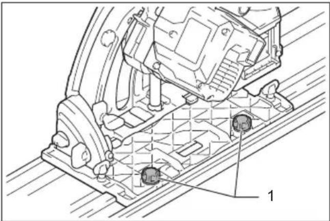
Place the tool on the rear end of guide rail. Turn two adjusting screws on the tool base so that the tool slides smoothly without a clatter. Hold both the front grip and rear handle of the tool firmly. Turn on the tool, press down the tool to the preset cutting depth and cut the splinterguard along the full length with a stroke. Now the edge of the splinterguard corresponds to the cutting edge.
natural_image
Technical line drawing of a mechanical assembly with no visible text or symbols▶ 1. Adjusting screws
When bevel cutting with the guide rail, use the slide lever to prevent the tool from falling over. Move the slide lever on the tool base in the direction of arrow so that it engages the undercut groove in the guide rail.
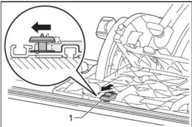
- Slide lever
Sub base (Guide rule)
Optional accessory
⚠️CAUTION: Make sure that the sub base is securely installed in the correct position before use. Improper attachment may cause dangerous kickback.
By using the sub base as a guide rule, you can perform extra-accurate straight cuts. Loosen the clamping screws and slide the sub base out from the tool then insert it upside down.
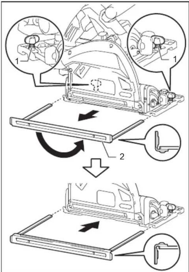
▶ 1. Clamping screw 2. Sub base
Simply slide the fence of the sub base snugly against the side of the workpiece and secure it in position with the clamping screws. It also makes repeated cuts of uniform width possible.

▶ 1. Clamping screw 2. Sub base
Plunge cutting (Cutting-out)
⚠ WARNING: To avoid a kickback, be sure to observe the following instructions.

▶ 1. Rear edge of tool base 2. Fixed stop
When using the tool without guide rail, place the tool on the workpiece with the rear edge of tool base against a fixed stop or equivalent which is devised by an operator.
When using the tool with guide rail, place the tool on the guide rail with the rear edge of tool base against a fixed stop or equivalent which is clamped on the guide rail.
Hold the tool firmly with one hand on the front grip and the other on the tool handle. Then push in the lock-off button and turn the tool on and wait until the blade attains full speed. Now press down the saw head slowly to the preset depth of cut and simply move the tool forward to the desired plunge position.
NOTE: The markings on the side of the blade guard show the front and rear cutting points of the saw blade at the maximum cutting depth when using the guide rail.

▶ 1. Front cutting point 2. Rear cutting point
Guide device
Optional accessory
Use of the bevel guide allows exact miter cuts with angles and fitting works.
Use of the clamp ensures firm hold of workpiece on the table.
WIRELESS ACTIVATION FUNCTION
What you can do with the wireless activation function
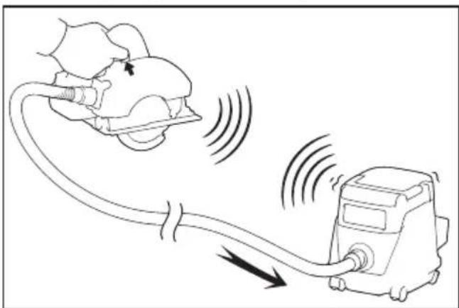
The wireless activation function enables clean and comfortable operation. By connecting a supported vacuum cleaner to the tool, you can run the vacuum cleaner automatically along with the switch operation of the tool.
natural_image
Line drawing of a device emitting sound waves from a device with a cloud-like top (no text or symbols)To use the wireless activation function, prepare following items:
• A wireless unit (optional accessory)
• A vacuum cleaner which supports the wireless activation function
The overview of the wireless activation function setting is as follows. Refer to each section for detail procedures.
- Installing the wireless unit
- Tool registration for the vacuum cleaner
- Starting the wireless activation function
Installing the wireless unit
Optional accessory
CAUTION: Place the tool on a flat and stable surface when installing the wireless unit.
NOTICE: Clean the dust and dirt on the tool before installing the wireless unit. Dust or dirt may cause malfunction if it comes into the slot of the wireless unit.
NOTICE: To prevent the malfunction caused by static, touch a static discharging material, such as a metal part of the tool, before picking up the wireless unit.
NOTICE: When installing the wireless unit, always be sure that the wireless unit is inserted in the correct direction and the lid is completely closed.
- Open the lid on the tool as shown in the figure.

-
Lid
-
Insert the wireless unit to the slot and then close the lid.
When inserting the wireless unit, align the projections with the recessed portions on the slot.

▶ 1. Wireless unit 2. Projection 3. Lid 4. Recessed portion
When removing the wireless unit, open the lid slowly. The hooks on the back of the lid will lift the wireless unit as you pull up the lid.

▶ 1. Wireless unit 2. Hook 3. Lid
After removing the wireless unit, keep it in the supplied case or a static-free container.
NOTICE: Always use the hooks on the back of the lid when removing the wireless unit. If the hooks do not catch the wireless unit, close the lid completely and open it slowly again.
Tool registration for the vacuum cleaner
NOTE: A Makita vacuum cleaner supporting the wireless activation function is required for the tool registration.
NOTE: Finish installing the wireless unit to the tool before starting the tool registration.
NOTE: During the tool registration, do not pull the switch trigger or turn on the power switch on the vacuum cleaner.
NOTE: Refer to the instruction manual of the vacuum cleaner, too.
If you wish to activate the vacuum cleaner along with the switch operation of the tool, finish the tool registration beforehand.
-
Install the batteries to the vacuum cleaner and the tool.
-
Set the stand-by switch on the vacuum cleaner to "AUTO".

▶ 1. Stand-by switch
- Press the wireless activation button on the vacuum cleaner for 3 seconds until the wireless activation lamp blinks in green. And then press the wireless activation button on the tool in the same way.

▶ 1. Wireless activation button 2. Wireless activation lamp
If the vacuum cleaner and the tool are linked successfully, the wireless activation lamps will light up in green for 2 seconds and start blinking in blue.
NOTE: The wireless activation lamps finish blinking in green after 20 seconds elapsed. Press the wireless activation button on the tool while the wireless activation lamp on the cleaner is blinking. If the wireless activation lamp does not blink in green, push the wireless activation button briefly and hold it down again.
NOTE: When performing two or more tool registrations for one vacuum cleaner, finish the tool registration one by one.
Starting the wireless activation function
NOTE: Finish the tool registration for the vacuum cleaner prior to the wireless activation.
NOTE: Refer to the instruction manual of the vacuum cleaner, too.
After registering a tool to the vacuum cleaner, the vacuum cleaner will automatically runs along with the switch operation of the tool.
- Install the wireless unit to the tool.
- Connect the hose of the vacuum cleaner with the tool.

natural_image
Line drawing of a mechanical device with hoses and a flat blade, no text or symbols present- Set the stand-by switch on the vacuum cleaner to "AUTO".
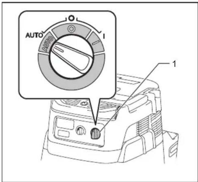
▶ 1. Stand-by switch
- Push the wireless activation button on the tool briefly. The wireless activation lamp will blink in blue.

▶ 1. Wireless activation button 2. Wireless activation lamp
- Pull the switch trigger of the tool. Check if the vacuum cleaner runs while the switch trigger is being pulled.
To stop the wireless activation of the vacuum cleaner, push the wireless activation button on the tool.
NOTE: The wireless activation lamp on the tool will stop blinking in blue when there is no operation for 2 hours. In this case, set the stand-by switch on the vacuum cleaner to "AUTO" and push the wireless activation button on the tool again.
NOTE: The vacuum cleaner starts/stops with a delay. There is a time lag when the vacuum cleaner detects a switch operation of the tool.
NOTE: The transmission distance of the wireless unit may vary depending on the location and surrounding circumstances.
NOTE: When two or more tools are registered to one vacuum cleaner, the vacuum cleaner may start running even if you do not pull the switch trigger because another user is using the wireless activation function.
Description of the wireless activation lamp status

▶ 1. Wireless activation lamp
The wireless activation lamp shows the status of the wireless activation function. Refer to the table below for the meaning of the lamp status.
| Status Wireless activation lamp Description | |||||
| Standby Blue | On | Blinking | Duration | ||
| 2 hours The wireless activation of the vacuum cleaner is available. The lamp will automatically turn off when no operation is performed for 2 hours. | |||||
| When the tool is running. | The wireless activation of the vacuum cleaner is available and the tool is running. | ||||
| Tool registration | Green | ☐ | 20 seconds Ready for the tool registration. Waiting for the registration by the vacuum cleaner. | ||
| ☐ | 2 seconds The tool registration has been finished. The wireless activation lamp will start blinking in blue. | ||||
| Cancelling tool registration | Red | ☐ | 20 seconds Ready for the cancellation of the tool registration. Waiting for the cancellation by the vacuum cleaner. | ||
| ☐ | 2 seconds The cancellation of the tool registration has been finished. The wireless activation lamp will start blinking in blue. | ||||
| Others Red | ☐ | 3 seconds The power is supplied to the wireless unit and the wireless activation function is starting up. | |||
| Off | - | - | The wireless activation of the vacuum cleaner is stopped. | ||
Cancelling tool registration for the vacuum cleaner
Perform the following procedure when cancelling the tool registration for the vacuum cleaner.
- Install the batteries to the vacuum cleaner and the tool.
- Set the stand-by switch on the vacuum cleaner to "AUTO".

▶ 1. Stand-by switch
- Press the wireless activation button on the vacuum cleaner for 6 seconds. The wireless activation lamp blinks in green and then become red. After that, press the wireless activation button on the tool in the same way.

▶ 1. Wireless activation button 2. Wireless activation lamp
If the cancellation is performed successfully, the wireless activation lamps will light up in red for 2 seconds and start blinking in blue.
NOTE: The wireless activation lamps finish blinking in red after 20 seconds elapsed. Press the wireless activation button on the tool while the wireless activation lamp on the cleaner is blinking. If the wireless activation lamp does not blink in red, push the wireless activation button briefly and hold it down again.
Troubleshooting for wireless activation function
Before asking for repairs, conduct your own inspection first. If you find a problem that is not explained in the manual, do not attempt to dismantle the tool. Instead, ask Makita Authorized Service Centers, always using Makita replacement parts for repairs.
| State of abnormality Probable cause | (malfunction) Remedy | |
| The wireless activation lamp does not light/blink. | The wireless unit is not installed into the tool. The wireless unit is improperly installed into the tool. | Install the wireless unit correctly. |
| The terminal of the wireless unit and/or the slot is dirty. | Gently wipe off dust and dirt on the terminal of the wireless unit and clean the slot. | |
| The wireless activation button on the tool has not been pushed. | Push the wireless activation button on the tool briefly. | |
| The stand-by switch on the vacuum cleaner is not set to "AUTO". | Set the stand-by switch on the vacuum cleaner to "AUTO". | |
| No power supply | Supply the power to the tool and the vacuum cleaner. | |
| Cannot finish tool registration / cancelling tool registration successfully. | The wireless unit is not installed into the tool. The wireless unit is improperly installed into the tool. | Install the wireless unit correctly. |
| The terminal of the wireless unit and/or the slot is dirty. | Gently wipe off dust and dirt on the terminal of the wireless unit and clean the slot. | |
| The stand-by switch on the vacuum cleaner is not set to "AUTO". | Set the stand-by switch on the vacuum cleaner to "AUTO". | |
| No power supply | Supply the power to the tool and the vacuum cleaner. | |
| Incorrect operation | Push the wireless activation button briefly and perform the tool registration/cancellation procedures again. | |
| The tool and vacuum cleaner are away from each other (out of the transmission range). | Get the tool and vacuum cleaner closer to each other. The maximum transmission distance is approximately 10 m however it may vary according to the circumstances. | |
| Before finishing the tool registration/cancellation; - the switch trigger on the tool is pulled or; - the power button on the vacuum cleaner is turned on. | Push the wireless activation button briefly and perform the tool registration/cancellation procedures again. | |
| The tool registration procedures for the tool or vacuum cleaner have not finished. | Perform the tool registration procedures for both the tool and the vacuum cleaner at the same timing. | |
| Radio disturbance by other appliances which generate high-intensity radio waves. | Keep the tool and vacuum cleaner away from the appliances such as Wi-Fi devices and microwave ovens. | |
| The vacuum cleaner does not run along with the switch operation of the tool. | The wireless unit is not installed into the tool. The wireless unit is improperly installed into the tool. | Install the wireless unit correctly. |
| The terminal of the wireless unit and/or the slot is dirty. | Gently wipe off dust and dirt on the terminal of the wireless unit and clean the slot. | |
| The wireless activation button on the tool has not been pushed. | Push the wireless activation button briefly and make sure that the wireless activation lamp is blinking in blue. | |
| The stand-by switch on the vacuum cleaner is not set to "AUTO". | Set the stand-by switch on the vacuum cleaner to "AUTO". | |
| More than 10 tools are registered to the vacuum cleaner. | Perform the tool registration again. If more than 10 tools are registered to the vacuum cleaner, the tool registered earliest will be cancelled automatically. | |
| The vacuum cleaner erased all tool registrations. | Perform the tool registration again. | |
| No power supply | Supply the power to the tool and the vacuum cleaner. | |
| The tool and vacuum cleaner are away from each other (out of the transmission range). | Get the tool and vacuum cleaner closer each other. The maximum transmission distance is approximately 10 m however it may vary according to the circumstances. | |
| Radio disturbance by other appliances which generate high-intensity radio waves. | Keep the tool and vacuum cleaner away from the appliances such as Wi-Fi devices and microwave ovens. | |
| The vacuum cleaner runs while the tool's switch trigger is not pulled. | Other users are using the wireless activation of the vacuum cleaner with their tools. | Turn off the wireless activation button of the other tools or cancel the tool registration of the other tools. |
MAINTENANCE
⚠️CAUTION: Always be sure that the tool is switched off and the battery cartridge is removed before attempting to perform inspection or maintenance.
CAUTION: Clean out the guard to ensure there is no accumulated sawdust which may impede the operation of the guarding system. A dirty guarding system may limit the proper operation which could result in serious personal injury. The most effective way to accomplish this cleaning is with compressed air. If the dust is being blown out of the guard, be sure the proper eye and breathing protection is used.
NOTICE: Never use gasoline, benzine, thinner, alcohol or the like. Discoloration, deformation or cracks may result.
To maintain product SAFETY and RELIABILITY, repairs, any other maintenance or adjustment should be performed by Makita Authorized or Factory Service Centers, always using Makita replacement parts.
Adjusting 0°-cut and 45°-cut accuracy
NOTICE: Do not engage the levers for -1irc bevel angle when adjusting 0irc -cut accuracy.
NOTICE: Do not engage the lever for 48irc bevel angle when adjusting 45irc -cut accuracy.
These adjustments have been made at the factory. But if they are off, you can adjust them as the following procedures.
- Slightly loosen the clamping screws on the front and rear of the tool.
- Adjust the blade angle.

▶ 1. Triangular rule
To adjust the 0irc -cut accuracy, make the base perpendicular to the blade using a triangular rule, square rule, etc. by turning the adjusting bolt.

natural_image
Technical line drawing of a mechanical component with labeled part '1' (no text or symbols beyond label)▶ 1. Adjusting bolt for 0irc -cut
To adjust the 45irc -cut accuracy, make the base 45irc to the blade using a triangular rule by turning the adjusting bolt.

natural_image
Technical line drawing of a mechanical component with labeled parts (no text or symbols present)▶ 1. Adjusting bolt for 45irc -cut
- Tighten the clamping screws and make a test cut.
OPTIONAL ACCESSORIES
⚠️CAUTION: These accessories or attachments are recommended for use with your Makita tool specified in this manual. The use of any other accessories or attachments might present a risk of injury to persons. Only use accessory or attachment for its stated purpose.
If you need any assistance for more details regarding these accessories, ask your local Makita Service Center.
- Circular saw blade
- Sub base
- Dust bag
- Front cuff 24
- Hex wrench
- Guide rail
- Bevel guide
- Clamp
- Sheet
- Rubber sheet
- Position sheet
- Wireless unit
• Makita genuine battery and charger
NOTE: Some items in the list may be included in the tool package as standard accessories. They may differ from country to country.
Makita Europe N.V.
Jan-Baptist Vinkstraat 2, 3070 Kortenberg, Belgium
Makita Corporation
3-11-8, Sumiyoshi-cho, Anjo, Aichi 446-8502 Japan
- Cordless Plunge Cut Saw
- SP001G
- SPECIFICATIONS
- Applicable battery cartridge and charger
- Symbols
- Intended use
- Noise
- Vibration
- EC Declaration of Conformity
- For European countries only
- SAFETY WARNINGS
- General power tool safety warnings
- Save all warnings and instructions for future reference.
- Work area safety
- Electrical safety
- Personal safety
- Power tool use and care
- Battery tool use and care
- Service
- Cordless circular saw safety warnings
- Cutting procedures
- Kickback causes and related warnings
- Guard function
- Additional safety warnings
- SAVE THESE INSTRUCTIONS.
- Important safety instructions for battery cartridge
- Tips for maintaining maximum battery life
- Important safety instructions for wireless unit
- FUNCTIONAL DESCRIPTION
- Installing or removing battery cartridge
- Tool / battery protection system
- Overload protection
- Overheat protection
- Overdischarge protection
- Indicating the remaining battery capacity
- Adjusting depth of cut
- ⚠️ CAUTION: After adjusting the depth of cut, always tighten the clamping screw securely.
- Quick stop button for 2 to 3 mm depth of cut when using guide rail (optional accessory)
- Bevel cutting
- Positive stopper
- 48°-bevel cutting
- -1°-bevel cutting
- When using the tool without guide rail
- When using the tool with guide rail
- Switch action
- Speed adjusting dial
- Electronic function
- Constant speed control
- Soft start feature
- Electric brake
- ASSEMBLY
- Hex wrench storage
- Removing or installing circular saw blade
- Blade guard cleaning
- Connecting a vacuum cleaner
- Optional accessory
- Adjusting angle of dust nozzle
- OPERATION
- Section cutting (ordinary sawing)
- Guide rail
- Sub base (Guide rule)
- Plunge cutting (Cutting-out)
- Guide device
- WIRELESS ACTIVATION FUNCTION
- What you can do with the wireless activation function
- Installing the wireless unit
- Tool registration for the vacuum cleaner
- Starting the wireless activation function
- Description of the wireless activation lamp status
- Cancelling tool registration for the vacuum cleaner
- Troubleshooting for wireless activation function
- MAINTENANCE
- Adjusting 0°-cut and 45°-cut accuracy
- OPTIONAL ACCESSORIES
Brand : MAKITA
Model : SP001GD201
Category : Cordless plunge saw