HDC-I2/E-240 - Motherboard ECS - Free user manual and instructions
Find the device manual for free HDC-I2/E-240 ECS in PDF.

User questions about HDC-I2/E-240 ECS
0 question about this device. Answer the ones you know or ask your own.
Ask a new question about this device
Download the instructions for your Motherboard in PDF format for free! Find your manual HDC-I2/E-240 - ECS and take your electronic device back in hand. On this page are published all the documents necessary for the use of your device. HDC-I2/E-240 by ECS.
USER MANUAL HDC-I2/E-240 ECS
This publication, including all photographs, illustrations and software, is protected under international copyright laws, with all rights reserved. Neither this manual, nor any of the material contained herein, may be reproduced without written consent of the author.
Version 1.0
◆◆▲◆◆○◆□
The information in this document is subject to change without notice. The manufacturer makes no representations or warranties with respect to the contents hereof and specifically disclaims any implied warranties of merchantability or fitness for any particular purpose. The manufacturer reserves the right to revise this publication and to make changes from time to time in the content hereof without obligation of the manufacturer to notify any person of such revision or changes.
\*□✿✿○□\*✿✿□\*■✿□■
Microsoft, MS-DOS and Windows are registered trademarks of Microsoft Corp.
AMD, Phenom, Athlon, Sempron and Duron are registered trademarks of AMD Corporation.
Other product names used in this manual are the properties of their respective owners and are acknowledged.
This equipment has been tested and found to comply with the limits for a Class B digital device, pursuant to Part 15 of the FCC Rules. These limits are designed to provide reasonable protection against harmful interference in a residential installation. This equipment generates, uses, and can radiate radio frequency energy and, if not installed and used in accordance with the instructions, may cause harmful interference to radio communications. However, there is no guarantee that interference will not occur in a particular installation. If this equipment does cause harmful interference to radio or television reception, which can be determined by turning the equipment off and on, the user is encouraged to try to correct the interference by one or more of the following measures:
- Reorient or relocate the receiving antenna
- Increase the separation between the equipment and the receiver
- Connect the equipment onto an outlet on a circuit different from that to which the receiver is connected
- Consult the dealer or an experienced radio/TV technician for help
Shielded interconnect cables and a shielded AC power cable must be employed with this equipment to ensure compliance with the pertinent RF emission limits governing this device. Changes or modifications not expressly approved by the system's manufacturer could void the user's authority to operate the equipment.
✿✿✿✿☐✿✿☐■☐✿✿☐■☐○✿
This device complies with part 15 of the FCC rules. Operation is subject to the following conditions:
- This device may not cause harmful interference, and
- This device must accept any interference received, including interference that may cause undesired operation
This class B digital apparatus meets all requirements of the Canadian Interference-causing Equipment Regulations.
The manual consists of the following:
Chapter 1 Introducing the Motherboard
Describes features of the motherboard.
Go to

page 1
Chapter 2 Installing the Motherboard
Describes installation of motherboard components.
Go to

page 7
Chapter 3 Using BIOS
Provides information on using the BIOS Setup Utility.
Go to

page 21
Chapter 4 Using the Motherboard Software
Describes the motherboard software
Go to

page 41
Chapter 5 Setting Up eJIFFY
Describes the eJIFF setting up
Go to

page 45
Chapter 6 Trouble Shooting
Provides basic trouble shooting tips
Go to

page 57
Preface i
✿✿✿☐▼✿☐ c»
Introducing the Motherboard 1
Introduction....1
Feature....2
Motherboard Components....5
✿✿✿☐▼※☐ ✗
Installing the Motherboard 7
Safety Precautions....7
Choosing a Computer Case....7
Installing the Motherboard in a Case....7
Checking Jumper Settings......8
Setting Jumpers....8
Checking Jumper Settings....9
Jumper Settings....9
Installing Hardware....10
Installing Memory Modules....10
Expansion Slots....11
Connecting Optional Devices....13
Installing a Hard Disk Drive/CD-ROM/SATA Hard Drive...16
Connecting I/O Devices....17
Connecting Case Components....18
Front Panel Header....20
◆◆◆□▼◆□ √ ◆
Using BIOS 21
About the Setup Utility.... 21
The Standard Configuration....21
Entering the Setup Utility....21
Resetting the default CMOS values....22
Using BIOS....23
BIOS Navigation Key....23
Main Menu....23
Advanced Menu....24
Chipset Menu....33
Frequency/Voltage Control Menu....35
Boot Menu....36
Security Menu....37
Save & Exit Setup....38
Updating the BIOS....40
◆◆◆◆◆◆◆
√ √
Using the Motherboard Software 41
About the Software DVD-ROM/CD-ROM....41
Auto-installing under Windows XP/Vista/7......41
Running Setup....42
Manual Installation....44
Utility Software Reference....44
* * * * * * * X
√X
Setting Up eJIFFY 45
Introduction......45
Installation and BIOS Setup....46
Entering eJIFFY....49
Features Icons....50
Usage FAQ....51
◆◆◆◆□▼◆□×
XX XX
Trouble Shooting 57
Start up problems during assembly....57
Start up problems after prolong use....58
Maintenance and care tips....58
Basic Troubleshooting Flowchart....59
Introduction
Thank you for choosing the HDC-I2 motherboard of high performance, enhanced function. This motherboard has onboard FT1 CPU (AMD single core E-240 APU/AMD dual core E-350 APU/AMD dual core C-50 APU/AMD singlr-core C-30 APU)* with a Mini-ITX form factor of 170 x 170 mm.
The motherboard incorporates the AMD Hudson D1 FCH chipset. The HDC-I2 supports one PCI slot which full compliant with PCI rev 2.3 specification at 33 MHz. This motherboard supports up to 8 GB of system memory with single channel DDR3 1066/800 MHz. It implements an EHCI compliant interface that provides twelve USB 2.0 ports (eight USB 2.0 ports and two USB 2.0 headers support additional four USB 2.0 ports).
The motherboard is equipped with advanced full set of I/O ports in the rear panel, including one DVI port (optiona HDMI port), one VGA port, eight USB 2.0 ports, one LAN port, and audio jacks for microphone, line-in and line-out.

*The onboard CPU is optional, please take the actual motherboard as the standard.
Note: The eJIFFY function is optional, basing on the different CPU using on the motherboard, please take the actual product for the standard.
Feature
Processor
The motherboard uses onboard AMD FT1 CPU that carries the following features:
- The AMD FT1 processor combines the central processing unit (CPU) with the graphics processing unit (GPU) in a single-chip Accelerated Processing Unit (APU) package.
- The APU connects to the Fusion Controller Hub (FCH) through the Unified Media Interface (UMI) to provide connections to the different system devices.
Chipset
The AMD Hudson D1 FCH Chipset is a single-chip with proven reliability and performance.
- PCI slot compliants with PCI Rev 2.3 interface at 33 MHz
- Integrated SATA 3.0 Gb/s Host Controller
- Twelve USB 2.0 ports supported
• Supports Unified Media interface(UMI), SMBus controller, and High Definition Audio
• Supports Serial Peripheral Interface (SPI) - Enhanced DMA Controller, power management, hardware monitoring, interrupt controller, and clock function.
Memory
• Supports DDR3 1066/800 SDRAM with single-channel architecture
- Accommodates two unbuffered DIMMs
- Up to 4GB per DIMM with maximum memory size up to 8GB
Onboard LAN (optional)
• Supports PCI Express ™1.1
- Integrated 10/100/1000 transceiver
- Integrated Switching Regulator
- Wake-on-LAN and remote wake-up support
• Supports PCI Express TM 1.1
- Integrated 10/100 transceiver
- Integrated Linear Regulator
- Wake-on-LAN and remote wake-up support
Audio
This motherboard may support the following Audio chipset:
• 5.1 Channel High Definition Audio Codec
- Exceeds Microsoft Windows Logo Program (WLP) Requirements
• ADCs support 44.1k/48k/88.2K/96K/192KHz sample rate
• Power Support: Digital: 3.3V; Analog: 5.0V
Expansion Options
The motherboard comes with the following expansion options:
- One PCI slot
- Two 7-pin SATA connectors
Integrated I/O
The motherboard has a full set of I/O ports and connectors:
• One DVI port (optional HDMI port)
- One VGA port
- Eight USB 2.0 ports
- One LAN port
• Audio jacks for microphone, line-in and line-out
BIOS Firmware
This motherboard uses AMI BIOS that enables users to configure many system features including the following:
- Power management
- Wake-up alarms
- CPU parameters
• CPU and memory timing
The firmware can also be used to set parameters for different processor clock speeds.

-
Some hardware specifications and software items are subject to change without prior notice.
-
Due to chipset limitation, we recommend that motherboard be operated in the ambiance between 0 and 50^ C.
Specifications
| CPU | • Onboard AMD FT1 CPU(AMD single core E-240 APU/ AMD dual core E-350 APU/AMD dual core C-50 APU/AMD single-core C-30 APU)* |
| Chipset | • AMD Hudson D1 chipset |
| Memory | • Single-channel DDR3 memory architecture• 2 x 240-pin DDR3 DIMM sockets support up to 8 GB• Supports 1066/800 DDR3 SDRAM |
| Expansion Slots | • 1 x PCI slot |
| Storage | • Supported by AMD Hudson D1 chipset• 2 x Serial ATA 3.0 Gb/s devices |
| Audio | • VIA VT1705 |
| LAN | • AR8151 GigaLAN (optional 10/100 LAN AR8152) |
| Rear Panel I/O | • 1 x DVI port (optional HDMI port)• 1 x VGA port• 8 x USB 2.0 ports• 1 x RJ45 LAN connector• 1 x Audio port (Line in, microphone in, line out) |
| Internal I/OConnectors & Headers | • 1 x 24-pin ATX Power Supply connector• 1 x 4-pin CPU_FAN connector• 1 x 3-pin SYS_FAN connector• 2 x USB 2.0 headers• 1 x Front panel audio header• 1 x Speaker header• 1 x LVDS header (optional)• 1 x CASE open header• 1 x 10-pin Front panel switch/LED header• 2 x SATA 3Gb/s connectors |
| System BIOS | • AMI BIOS with 16Mb SPI Flash ROM• Supports ACPI & DMI• Supports Plug and Play, STR(S3)/STD(S4), Hardware monitor,• Audio, LAN, can be disabled in BIOS• Supports Dual Display (optional) |
Form Factor • Mini-ITX 170mm x 170mm

*The onboard CPU is optional, please take the actual motherboard as the standard.
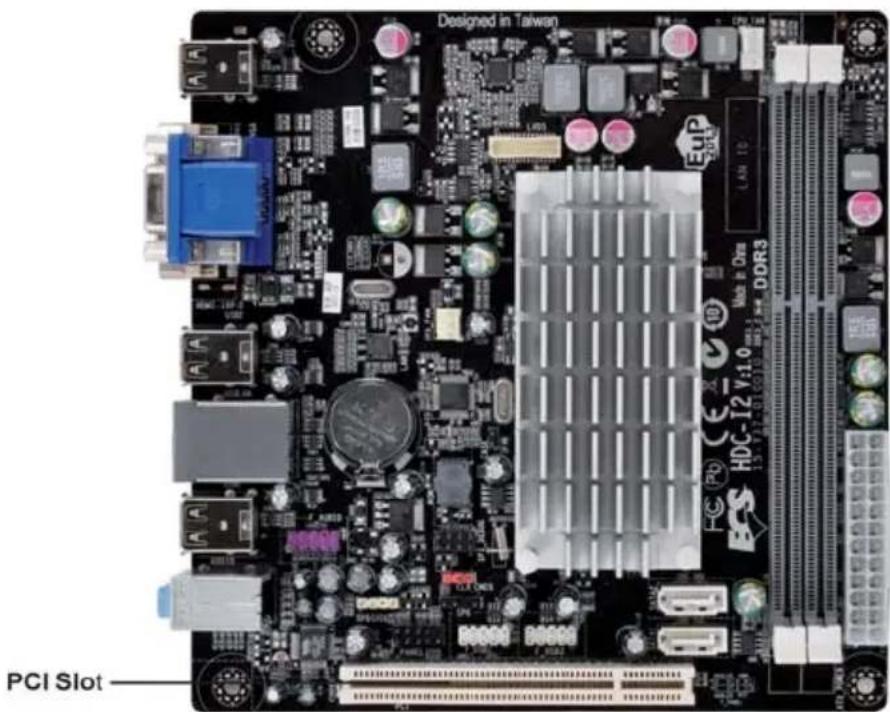
Motherboard Components
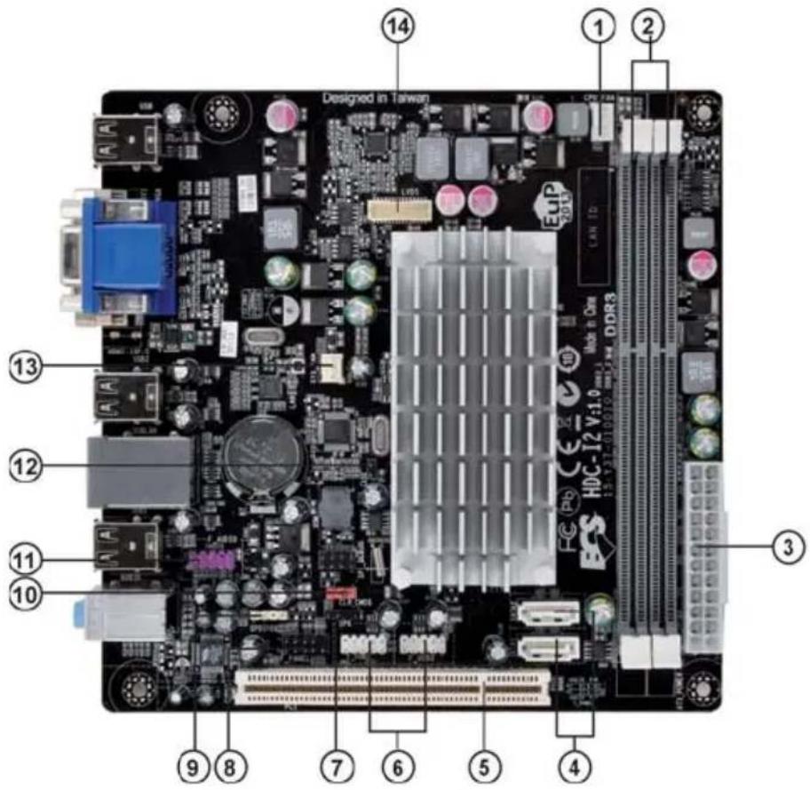
text_image
Designed in Taiwan ① ② ③ ④ ⑤ ⑥ ⑦ ⑧ ⑨ ⑩ ⑪ ⑫ ⑬ HDC-12 V:1.0 DDR3 LED 7.284 MHz CPU 7.284 MHz LED 7.284 MHz DDR3 LED 7.284 MHz LED 7.284 MHz LED 7.284 MHz LED 7.284 MHz LED 7.284 MHz LED 7.284 MHz LED 7.284 MHz LED 7.284 MHz LED 7.284 MHz LED 7.284 MHz LED 7.284 MHz LED 7.284 MHzTable of Motherboard Components
| LABEL COMPONENTS | |
| 1. CPU_FAN CPU cooling fan connector | |
| 2. DDR3_1~2 240-pin DDR3 SDRAM slots | |
| 3. ATX_POWER Standard 24-pin ATX power connector | |
| 4. SATA1~2 Serial ATA connectors | |
| 5. PCI 32-bit add-on card slot | |
| 6. F_USB1~2 Front panel USB headers | |
| 7. SPK Internal speaker header | |
| 8. F_PANEL Front panel switch/LED header | |
| 9. SPDIFO SPDIF out header | |
| 10. CLR_CMOS Clear CMOS jumper | |
| 11. F_AUDIO1 Front panel audio header | |
| 12. CASE CASE open header | |
| 13. SYS_FAN System cooling fan connector | |
| 14. LVDS (optional) Low Voltage Differential Signaling Transmitter Interfaces |
This concludes Chapter 1. The next chapter explains how to install the motherboard.
×
★★O□
Safety Precautions
- Follow these safety precautions when installing the motherboard
- Wear a grounding strap attached to a grounded device to avoid damage from static electricity
- Discharge static electricity by touching the metal case of a safely grounded object before working on the motherboard
- Leave components in the static-proof bags they came in
- Hold all circuit boards by the edges. Do not bend circuit boards
Choosing a Computer Case
There are many types of computer cases on the market. The motherboard complies with the specifications for the ITX system case. First, some features on the motherboard are implemented by cabling connectors on the motherboard to indicators and switches on the system case. Make sure that your case supports all the features required. Secondly, this motherboard supports two enhanced IDE drives. Make sure that your case has sufficient power and space for all drives that you intend to install.
Most cases have a choice of I/O templates in the rear panel. Make sure that the I/O template in the case matches the I/O ports installed on the rear edge of the motherboard.
This motherboard carries an ITX form factor of 170 x 170 mm. Choose a case that accommodates this form factor.
Installing the Motherboard in a Case
Refer to the following illustration and instructions for installing the motherboard in a case.
Most system cases have mounting brackets installed in the case, which correspond the holes in the motherboard. Place the motherboard over the mounting brackets and secure the motherboard onto the mounting brackets with screws.
Ensure that your case has an I/O template that supports the I/O ports and expansion slots on your motherboard.

text_image
Designed in Taiwan HCP 10 27-35 Moto & Dev V4:10 DDR3
Do not over-tighten the screws as this can stress the motherboard.
Checking Jumper Settings
This section explains how to set jumpers for correct configuration of the motherboard.
Setting Jumpers
Use the motherboard jumpers to set system configuration options. Jumpers with more than one pin are numbered. When setting the jumpers, ensure that the jumper caps are placed on the correct pins.
The illustrations show a 2-pin jumper. When the jumper cap is placed on both pins, the jumper is SHORT. If you remove the jumper cap, or place the jumper cap on just one pin, the jumper is OPEN.
This illustration shows a 3-pin jumper. Pins 1 and 2 are SHORT.
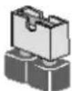
SHORT
OPEN

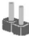
Checking Jumper Settings
The following illustration shows the location of the motherboard jumpers. Pin 1 is labeled.
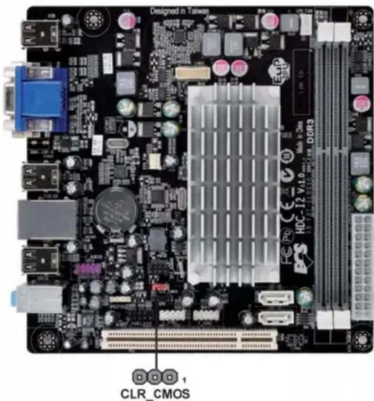
text_image
Designed in Taiwan CLR_CMOSJumper Settings
| Jumper | Type | Description | Setting (default) | |
| CLR_CMOS | 3-pin | CLEAR CMOS | 1-2: NORMAL2-3: CLEARBefore clearing the CMOS, make sure to turn the system off. |  1CLR_CMOS 1CLR_CMOS |

To avoid the system instability after clearing CMOS, we recommend users to enter the main BIOS setting page to "Load Default Settings" and then "Save & Exit Setup".
Installing Hardware
Installing Memory Modules
This motherboard accommodates two memory module. It can support two 240-pin DDR3 1066/800. The total memory capacity is 8 GB.
DDR3 SDRAM memory module table
| Memory module Memory Bus | |
| DDR3 800 400 MHz | |
| DDR3 1066 533 MHz |
You must install at least one module in any of the two slots. Total memory capacity is 8 GB.

Do not remove any memory module from its antistatic packaging until you are ready to install it on the motherboard. Handle the modules only by their edges. Do not touch the components or metal parts. Always wear a grounding strap when you handle the modules.
Installation Procedure
Refer to the following to install the memory modules.
1 This motherboard supports unbuffered DDR3 SDRAM.
2 Push the latches on each side of the DIMM slot down.
3 Align the memory module with the slot. The DIMM slots are keyed with notches and the DIMMs are keyed with cutouts so that they can only be installed correctly.
4 Check that the cutouts on the DIMM module edge connector match the notches in the DIMM slot.
5 Install the DIMM module into the slot and press it firmly down until it seats correctly. The slot latches are levered upwards and latch on to the edges of the DIMM.
6 Install any remaining DIMM modules.

natural_image
Close-up of a hand inserting a memory card into a computer motherboard (no visible text or symbols)* For reference only
Expansion Slots
Installing Add-on Cards
The slots on this motherboard are designed to hold expansion cards and connect them to the system bus. Expansion slots are a means of adding or enhancing the motherboard's features and capabilities. With these efficient facilities, you can increase the motherboard's capabilities by adding hardware that performs tasks that are not part of the basic system.
text_image
Designed in Taiwan PCI Slot HDC-12 V1.0 DDR3PCI Slot
This motherboard is equipped with one standard PCI slot. PCI stands for Peripheral Component Interconnect and is a bus standard for expansion cards, which for the most part, is a supplement of the older ISA bus standard. The PCI slot on this board are PCI v2.3 compliant.

Before installing an add-on card, check the documentation for the card carefully. If the card is not Plug and Play, you may have to manually configure the card before installation.
Follow these instructions to install an add-on card:
1 Remove a blanking plate from the system case corresponding to the slot you are going to use.
2 Install the edge connector of the add-on card into the expansion slot. Ensure that the edge connector is correctly seated in the slot.
3 Secure the metal bracket of the card to the system case with a screw.

natural_image
Green printed circuit board with various electronic components and connectors (no visible text or labels)* For reference only

For some add-on cards, for example graphics adapters and network adapters, you have to install drivers and software before you can begin using the add-on card.
Connecting Optional Devices
Refer to the following for information on connecting the motherboard's optional devices:
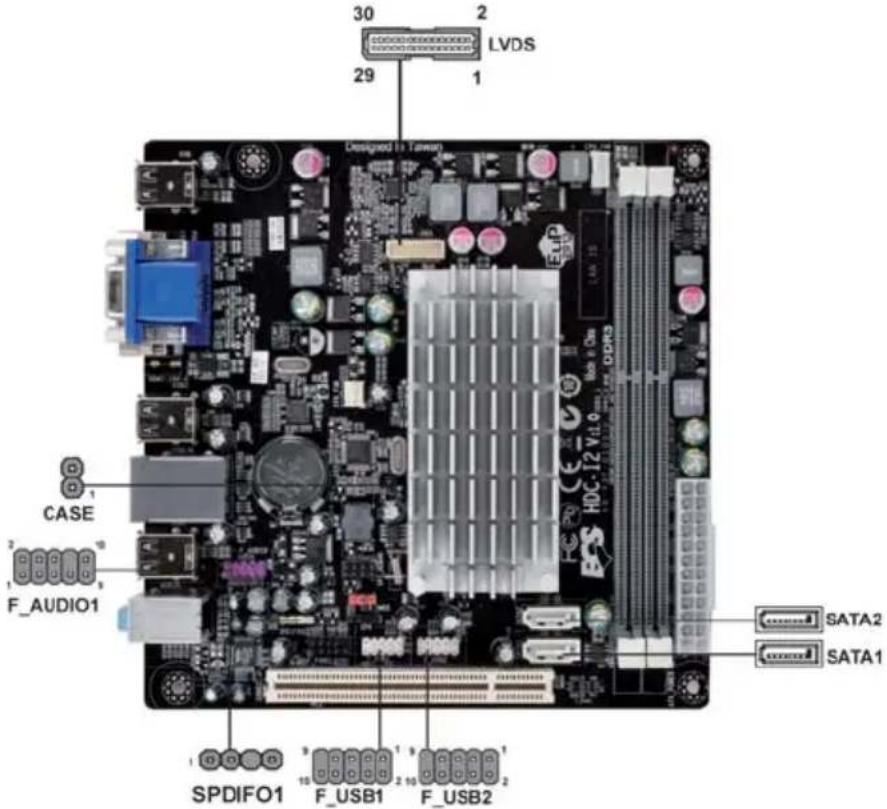
text_image
30 2 LVDS 29 1 DESIGNED BY: LVDS CASE F_AUDIO1 SPDIFO1 F_USB1 F_USB2 SATA2 SATA1F\_AUDIO: Front Panel Audio header
This header allows the user to install auxiliary front-oriented microphone and line-out ports for easier access.
| Pin Signal Name Pin Signal Name | |||
| 1 PORT 2L 2 AUD_GND | |||
| 3 PORT 2R 4 PRESENCE# | |||
| 5 PORT 2R 6 SENSE1_RETURN | |||
| 7 SENSE_SEND 8 KEY | |||
| 9 | PORT 2L | 10 | SENSE2_RETURN |
SATA1\~2: Serial ATA connectors
These connectors are use to support the new Serial ATA devices for the date transfer rates (3.0 Gb/s), simpler disk drive cabling and easier PC assembly. It eliminates limitations of the current Parallel ATA interface. But maintains register compatibility and software compatibility with Parallel ATA.
| n Signal Name | Pin Signal Name | |
| 1 Ground 2 TX+ | ||
| 3 TX-4 Ground | ||
| 5 RX-6 RX+ | ||
| 7 Ground - - | ||
CASE: Chassis Intrusion Detect Header
| Pin 1-2 Function | |
| Short | Case Open |
| Open | Case Close |
F\_USB1\~2: Front Panel USB headers
The motherboard has eight USB 2.0 ports installed on the rear edge I/O port array. Additionally, some computer cases have USB ports at the front of the case. If you have this kind of case, use auxiliary USB connector to connect the front-mounted ports to the motherboard.
| Pin | Signal Name | Function |
| 1 | USBPWR Front Panel | USB Power |
| 2 | USBPWR Front Panel | USB Power |
| 3 | USB_FP_P0-USB Port | 0 Negative Signal |
| 4 | USB_FP_P1-USB Port | 1 Negative Signal |
| 5 | USB_FP_P0+ USB Port | 0 Positive Signal |
| 6 | USB_FP_P1+ USBPort | 1 Positive Signal |
| 7 | GNDGround | |
| 8 | GND Ground | |
| 9 | Key No pin | |
| 10 | USB_FP_OC0 Overcurrent signal |

Please make sure that the USB cable has the same pin assignment as indicated above. A different pin assignment may cause damage or system hang-up.
SPDIFO: SPDIF out header
This is an optional header that provides an S/PDIF (Sony/Philips Digital Interface) output to digital multimedia device through optical fiber or coaxial connector.
| Pin | Signal Name | Function |
| 1 | SPDIF | SPDIF digital output |
| 2 | +5VA 5V analog Power | |
| 3 | Key | No pin |
| 4 | GND | Ground |
LVDS: LVDS connector (optional)
| Pin | Signal Name Pin Signal Name | |
| 1 | VDD | 2 VDD |
| 3 | GND | 4 USB_GND |
| 5 | V_LED | 6 V_LED |
| 7 | GND | 8 GND |
| 9 | PWM_LED | 10 EN_LED |
| 11 | USB_VCC | 12 USB_D- |
| 13 | USB_D+ | 14 USB_GND |
| 15 | V_EDID | 16 GND |
| 17 | RXIN0- | 18 RXIN0+ |
| 19 | GND | 20 RXIN1- |
| 21 | RXIN1+ 22 GND | |
| 23 | RXIN2- 24 RXIN2+ | |
| 25 | GND 26 RXCLK+ | |
| 27 | RXCLK- 28 GND | |
| 29 | DATA-EDID 30 CLK-EDID | |
Installing a Hard Disk Drive/CD-ROM/SATA Hard Drive
This section describes how to install IDE devices such as a hard disk drive and a CD-ROM drive.
About SATA Connectors
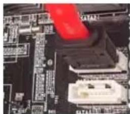
Your motherboard features two SATA connectors supporting a total of two drives. SATA refers to Serial ATA (Advanced Technology Attachment) is the standard interface for the IDE hard drives which are currently used in most PCs. These connectors are well designed and will only fit in one orientation. Locate the SATA connectors on the motherboard and follow the illustration below to install the SATA hard drives.
Installing Serial ATA Hard Drives
To install the Serial ATA (SATA) hard drives, use the SATA cable that supports the Serial ATA protocol. This SATA cable comes with one SATA power cable. You can connect either end of the SATA cable to the SATA hard drive or the connector on the motherboard.

SATA cable (optional)
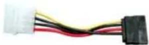
SATA power cable (optional)
Refer to the illustration below for proper installation:
1 Attach either cable end to the connector on the motherboard.
2 Attach the other cable end to the SATA hard drive.
3 Attach the SATA power cable to the SATA hard drive and connect the other end to the power supply.
natural_image
Close-up of a computer motherboard with a red laser chip inserted (no visible text or symbols)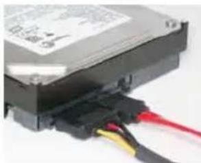
natural_image
Close-up of a black electronic component with red and yellow wires, no visible text or symbols
This motherboard supports the "Hot-Plug" function.
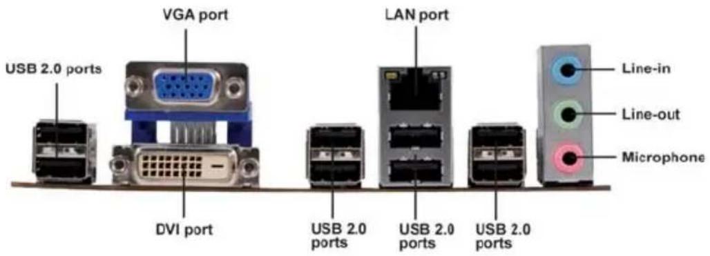
Connecting I/O Devices
The backplane of the motherboard has the following I/O ports:
text_image
USB 2.0 ports VGA port DVI port LAN port USB 2.0 ports USB 2.0 ports USB 2.0 ports Line-in Line-out MicrophoneDVI Port Connect the DVI port to the monitor.
VGA Port Connect your monitor to the VGA port.
USB 2.0 Ports Use the USB 2.0 ports to connect USB 2.0 devices.
LAN Port
Connect an RJ-45 jack to the LAN port to connect your computer to the Network.
Audio Ports
Use the three audio ports to connect audio devices. The first jack is for stereo line-in signal. The second jack is for stereo line-out signal. The third jack is for microphone.
Connecting Case Components
After you have installed the motherboard into a case, you can begin connecting the motherboard components. Refer to the following:
1 Connect the CPU cooling fan cable to CPU_FAN.
2 Connect the system cooling fan connector to SYS_FAN.
3 Connect the case switches and indicator LEDs to the F_PANEL.
4 Connect the standard power supply connector to ATX POWER.
5 Connect the case speaker cable to SPK.
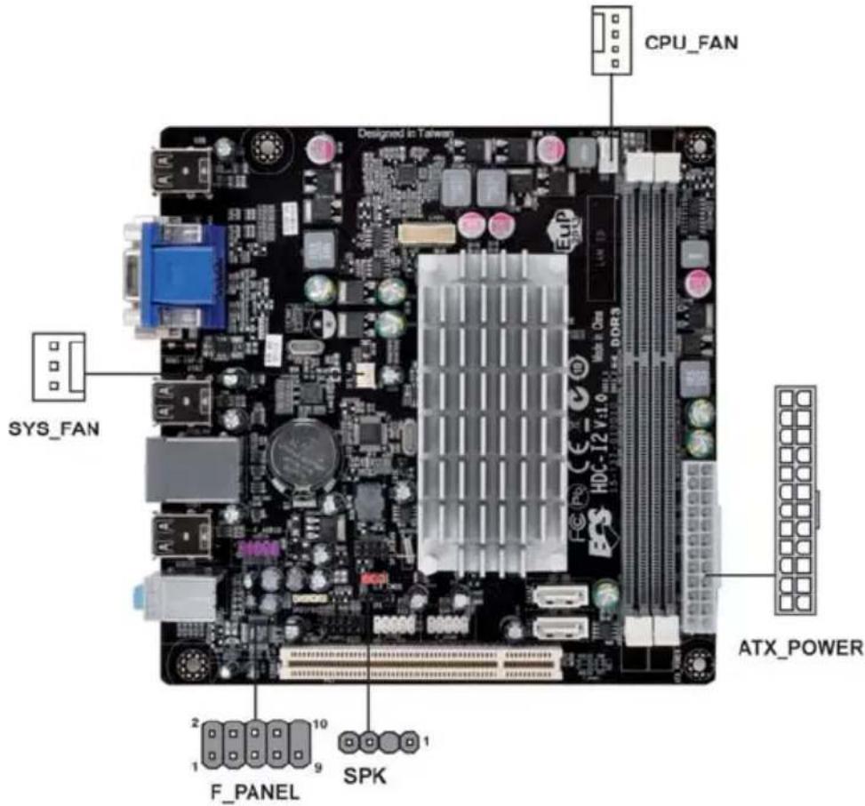
text_image
CPU_FAN DESIGNED IN TAIWEN SYS_FAN ATX_POWER F_PANEL SPK
Connecting 24-pin power cable
The ATX 24-pin connector allows you to connect to ATX v2.x power supply.
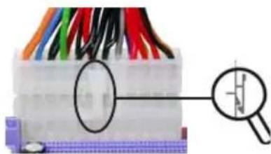
natural_image
Close-up of a multicolored electronic component with a magnified inset showing a small hole (no text or symbols visible)24-pin power cable
With ATX v2.x power supply, users please note that when installing 24-pin power cable, the latches of power cable and the ATX1 match perfectly.
CPU\_FAN: FAN Power Connector
| Pin | Signal Name | Function |
| 1 | GND System Ground | |
| 2 | +12V | Power +12V |
| 3 | Sense | Sensor |
| 4 | Control | CPU FAN control |

Users please note that the fan connector supports the CPU cooling fan of 1.1A \~ 2.2A (26.4W max) at +12V.
ATX\_POWER: ATX 24-pin Power Connector
| Pin | Signal Name | Pin | Signal Name |
| 1 +3.3V 13 +3.3V | |||
| 2 +3.3V 14 -12V | |||
| 3 Ground 15 Ground | |||
| 4 +5V 16 PS_ON | |||
| 5 Ground 17 Ground | |||
| 6 +5V 18 Ground | |||
| 7 Ground 19 Ground | |||
| 8 PWRGD 20 -5V | |||
| 9 +5VSB 21 +5V | |||
| 10 +12V 22 +5V | |||
| 11 +12V 23 +5V | |||
| 12 +3.3V 24 Ground |
SPK: Internal speaker
| Pin | Signal Name |
| 1 | VCC |
| 2 | Key |
| 3 | NC |
| 4 | Signal |
SYS\_FAN: System Cooling FAN Power Connector
| Pin | Signal Name | Function |
| 1 | GND | System Ground |
| 2 | +12V | Power +12V |
| 3 | Sense | Sensor |
Front Panel Header
The front panel header (F_PANEL) provides a standard set of switch and LED headers commonly found on ATX or Micro ATX cases. Refer to the table below for information:
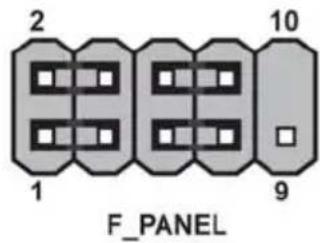
text_image
2 1 10 9 F_PANEL| Pin Signal Function Pin Signal Function | |||||
| 1 | HD_LED_P | Hard disk LED(+) | 2 | FP PWR/SLP | *MSG LED(+) |
| 3 | HD_LED_N | Hard disk LED(-) | 4 | FP PWR/SLP *MSG LED(-) | |
| 5 | RST_SW_N | Reset Switch(-) | 6 | PWR_SW_P Power Switch(+) | |
| 7 | RST_SW_P | Reset Switch(+) | 8 | PWR_SW_N Power Switch(-) | |
| 9 | RSVD Reserved | 10 | Key No pin | ||
* MSG LED (dual color or single color)
Hard Drive Activity LED
Connecting pins 1 and 3 to a front panel mounted LED provides visual indication that data is being read from or written to the hard drive. For the LED to function properly, an IDE drive should be connected to the onboard IDE interface. The LED will also show activity for devices connected to the SCSI (hard drive activity LED) connector.
Power/Sleep/Message waiting LED
Connecting pins 2 and 4 to a single or dual-color, front panel mounted LED provides power on/off, sleep, and message waiting indication.
Reset Switch
Supporting the reset function requires connecting pin 5 and 7 to a momentary-contact switch that is normally open. When the switch is closed, the board resets and runs POST.
Power Switch
Supporting the power on/off function requires connecting pins 6 and 8 to a momentary-contact switch that is normally open. The switch should maintain contact for at least 50 ms to signal the power supply to switch on or off. The time requirement is due to internal de-bounce circuitry. After receiving a power on/off signal, at least two seconds elapses before the power supply recognizes another on/off signal.
This concludes Chapter 2. The next chapter covers the BIOS.
About the Setup Utility
The computer uses the latest “American Megatrends Inc.” BIOS with support for Windows Plug and Play. The CMOS chip on the motherboard contains the ROM setup instructions for configuring the motherboard BIOS.
The BIOS (Basic Input and Output System) Setup Utility displays the system's configuration status and provides you with options to set system parameters. The parameters are stored in battery-backed-up CMOS RAM that saves this information when the power is turned off. When the system is turned back on, the system is configured with the values you stored in CMOS.
The BIOS Setup Utility enables you to configure:
- Hard drives, diskette drives and peripherals
• Video display type and display options - Password protection from unauthorized use
• Power Management features
The settings made in the Setup Utility affect how the computer performs. Before using the Setup Utility, ensure that you understand the Setup Utility options.
This chapter provides explanations for Setup Utility options.
The Standard Configuration
A standard configuration has already been set in the Setup Utility. However, we recommend that you read this chapter in case you need to make any changes in the future.
This Setup Utility should be used:
- when changing the system configuration
- when a configuration error is detected and you are prompted to make changes to the Setup Utility
- when trying to resolve IRQ conflicts
- when making changes to the Power Management configuration
- when changing the password or making other changes to the Security Setup
Entering the Setup Utility
When you power on the system, BIOS enters the Power-On Self Test (POST) routines. POST is a series of built-in diagnostics performed by the BIOS. After the POST routines are completed, the following message appears:
Press DEL to enter SETUP
Press the delete key to access BIOS Setup Utility.
| Main | Advanced | Chipset | Frequency/Voltage Control | Boot | Security | Save & Exit |
| BIOS InformationSystem Laguage [English]System Date [Sat 12/18/2010]System Time [23:51:29] | Choose the system default laguage.→ ←:Select Screen↑↓ :Select ItemEnter : Select+/- :Change Opt.F1:General HelpF2:Previous ValuesF3:Optimized DefaultsF4:Save & ExitESC:Exit | |||||
| Version 2.10.1208. Copyright (C) 2010, American Megatrends, Inc. | ||||||
Resetting the Default CMOS Values
When powering on for the first time, the POST screen may show a “CMOS Settings Wrong” message. This standard message will appear following a clear CMOS data at factory by the manufacturer. You simply need to Load Default Settings to reset the default CMOS values.
Note: Changes to system hardware such as different CPU, memories, etc. may also trigger this message.

text_image
American Megatrends HDC-I2 Release 10/13/2010 Version 2.02.1205. Copyright (C) 2010 American Megatrends, Inc. PressUsing BIOS
When you start the Setup Utility, the main menu appears. The main menu of the Setup Utility displays a list of the options that are available. A highlight indicates which option is currently selected. Use the cursor arrow keys to move the highlight to other options. When an option is highlighted, execute the option by pressing
Some options lead to pop-up dialog boxes that prompt you to verify that you wish to execute that option. Other options lead to dialog boxes that prompt you for information.
Some options (marked with a triangle ▶) lead to submenus that enable you to change the values for the option. Use the cursor arrow keys to scroll through the items in the submenu.
In this manual, default values are enclosed in parenthesis. Submenu items are denoted by a triangle ▶.

The default BIOS setting for this motherboard apply for most conditions with optimum performance. We do not suggest users change the default values in the BIOS setup and take no responsibility to any damage caused by changing the BIOS settings.
BIOS Navigation Keys
The BIOS navigation keys are listed below:
| KEY FUNCTION | |
| ESC | Exits the current menu |
| Scrolls through the items on a menu | |
| +/- Modifies the selected field's values | |
| Enter | Select |
| F1 General Help | |
| F2 Previous Value | |
| F3 Optimized Defaults | |
| F4 Save & Exit | |

For the purpose of better product maintenance, the manufacture reserves the right to change the BIOS items presented in this manual. The BIOS setup screens shown in this chapter are for reference only and may differ from the actual BIOS. Please visit the manufacture's website for updated manual.
Main Menu
When you enter the BIOS Setup program, the main menu appears, giving you an overview of the basic system information. Select an item and press
| Aptio Setup Utility - Copyright (C) 2010 American Megatrends, Inc. | |
| BIOS InformationSystem Laguage [English] | Choose the system default laguage. |
| System Date [Sat 12/18/2010]System Time [23:51:29] | → ← :Select Screen↑↓ :Select ItemEnter : Select+/- :Change Opt.F1:General HelpF2:Previous ValuesF3:Optimized DefaultsF4:Save & ExitESC:Exit |
| Version 2.10.1208. Copyright (C) 2010, American Megatrends, Inc. | |
Date & Time
The Date and Time items show the current date and time on the computer. If you are running a Windows OS, these items are automatically updated whenever you make changes to the Windows Date and Time Properties utility.
Advanced Menu
The Advanced menu items allow you to change the settings for the CPU and other system.
| Aptio Setup Utility - Copyright (C) 2010 American Megatrends, Inc.Main Advanced Chipset Frequency/Voltage Control Boot Security Save & Exit | |
| Legacy OpROM SupportLaunch PXE OpROM [Disabled]▶ECS eJIFFY Function▶LAN Configuration▶PC Health Status▶Power Management Setup▶ACPI Settings▶CPU Configuration▶SATA Configuration▶USB Configuration | Enable or Disable Boot Option for Legacy Network Devices. |
| → ← :Select Screen↑↓ :Select ItemEnter : Select+/- :Change Opt.F1:General HelpF2:Previous ValuesF3:Optimized DefaultsF4:Save & ExitESC:Exit | |
| Version 2.10.1208. Copyright (C) 2010, American Megatrends, Inc. | |
Launch PXE OpROM
The item enables or disables launch PXE Option ROM.
Launch Storage OpROM (Disabled)
The item enables or disables launch Storage Option ROM.
ECS eJIFFY Function
Scroll to this item and press
| Aptio Setup Utility - Copyright (C) 2010 American Megatrends, Inc.Main Advanced Chipset Frequency/Voltage Control Boot Security Save & Exit | |
| ECS eJIFFY FunctionECS eJIFFY Function [Disabled] | Make sure that the eJIFFY has been installed to hard disk. |
| → ←:Select Screen↑↓ :Select ItemEnter : Select+/- :Change Opt.F1:General HelpF2:Previous ValuesF3:Optimized DefaultsF4:Save & ExitESC:Exit | |
| Version 2.10.1208. Copyright (C) 2010, American Megatrends, Inc. | |
ECS eJIFFY Function (Disabled)
This item allows you to enable or disable ECS eJIFFY Function.
Press
LAN Configuration
The item in the menu shows the LAN-related information that the BIOS automatically detects.
| Main Advanced Chipset Frequency/Voltage Control Boot Security Save & Exit | |
| LAN ConfigurationOnboard LAN Controller [Enabled] | Enable or Disable Onboard LAN |
| → ← :Select Screen↑↓ :Select ItemEnter : Select+/- :Change Opt.F1:General HelpF2:Previous ValuesF3:Optimized DefaultsF4:Save & ExitESC:Exit | |
| Version 2.10.1208. Copyright (C) 2010, American Megatrends, Inc. | |
Onboard LAN Controller (Enabled)
Use this item to enable or disable the Onboard LAN.
Press
PC Health Status
On motherboards support hardware monitoring, this item lets you monitor the pacameters for critical voltages, temperatures and fan speeds.
| Aptio Setup Utility - Copyright (C) 2010 American Megatrends, Inc.Main Advanced Chipset Frequency/Voltage Control Boot Security Save & Exit | |
| Smart Fan FunctionCPU Tct1: +61System temperature: +35 CCPU FAN: 4249 RPMSYS FAN: N/AVDIMM: +1.531 V | → ← :Select Screen↑↓ :Select ItemEnter : Select+/- :Change Opt.F1:General HelpF2:Previous ValuesF3:Optimized DefaultsF4:Save & ExitESC:Exit |
| Version 2.10.1208. Copyright (C) 2010, American Megatrends, Inc. | |
▶Smart Fan Function
Scroll to this item and press
| Aptio Setup Utility - Copyright (C) 2010 American Megatrends, Inc. | |||||
| Main | Advanced | Chipset | Frequency/Voltage Control | Boot | Security Save & Exit |
| CPU Smart Fan Control [Enabled]Smart Fan Mode [Normal] | Enable CPU SmartFan | ||||
| High Limit Temperature 60Low Limit Temperature 37High Limit PWM 200Low Limit PWM 56SYS Smart Fan Control [Enabled]Smart Fan Mode [Normal] | → ←:Select Screen↑↓ :Select ItemEnter : Select+/- :Change Opt.F1:General HelpF2:Previous ValuesF3:Optimized DefaultsF4:Save & ExitESC:Exit | ||||
| High Limit Temperature 60Low Limit Temperature 37High Limit PWM 200Low Limit PWM 56 | |||||
| Version 2.10.1208. Copyright (C) 2010, American Megatrends, Inc. | |||||
CPU Smart FAN Control (Enabled)
This item allows you to enable/disable the control of the CPU fan speed by changing the fan voltage.
Smart Fan Mode (Normal)
This item allows you to select the fan mode (Normal, Quiet, Silent, or Manual) for a better operation environment. If you choose Normal mode, the fan speed will be auto adjusted depending on the CPU temperature. If you choose Quite mode, the fan speed will be auto minimized for quiet environment. If you choose Silent mode, the fan speed will be auto restricted to make system more quietly. If you choose Manual mode, the fan speed will be adjust depending on users' parameters.
SYS Smart Fan Control (Enabled)
This item enables you to define the System temperature by smartly adjusting the System Fan. When it is set at certain temperature, the SYS Fan PWM value will change accordingly.
Press
Power Management Setup
This page sets up some parameters for system power management operation.
| Aptio Setup Utility - Copyright (C) 2010 American Megatrends, Inc.Main Advanced Chipset Frequency/Voltage Control Boot Security Save & Exit | |
| Power Management SetupResume By PCI/PCI-E/Lan PME [Disabled]Resume By USB (S3) [Disabled]EUP Function [Enabled] | About Resume by PCI/PCI-E/Lan PME |
| → ← :Select Screen↑↓ :Select ItemEnter : Select+/- :Change Opt.F1:General HelpF2:Previous ValuesF3:Optimized DefaultsF4:Save & ExitESC:Exit | |
| Version 2.10.1208. Copyright (C) 2010, American Megatrends, Inc. | |
Resume By PCI/PCI-E/Lan PME (Disabled)
The system can be turned off with a software command. If you enable this item, the system can automatically resume if there is an incoming call on the PCI Modem or PCI LAN card. You must use an ATX power supply in order to use this feature. Use this item to do wake-up action if inserting the PCI card.
Resume By USB (S3) (Disabled)
This item allows you to enable/disable the USB device wakeup function from S3 mode.
EUP Support (Enabled)
This item allows user to enable or disable EUP support.
Press
ACPI Configuration
The item in the menu shows the highest ACPI sleep state when the system enters suspend.
| Aptio Setup Utility - Copyright (C) 2010 American Megatrends, Inc.Main Advanced Chipset Frequency/Voltage Control Boot Security Save & Exit | |
| ACPI ConfigurationACPI Sleep State [S3 (Suspend to RAM)] | Select the highest ACPI sleep state the system will enter when the SUSPEND button is pressed. |
| → ← :Select Screen↑↓ :Select ItemEnter : Select+/- :Change Opt.F1:General HelpF2:Previous ValuesF3:Optimized DefaultsF4:Save & ExitESC:Exit | |
| Version 2.10.1208. Copyright (C) 2010, American Megatrends, Inc. | |
ACPI Sleep State (S3(Suspend to RAM))
This item allows user to enter the APCI S3 (Suspend toRAM) Sleep State(default).
Press
CPU Configuration
The item in the menu shows the CPU.
| Aptio Setup Utility - Copyright (C) 2010 American Megatrends, Inc.Main Advanced Chipset Frequency/Voltage Control Boot Security Save & Exit | |
| CPU ConfigurationNodeo: AMD E-350 ProcessorDual Core Running @ 1618 MHz 1300 mVMax Speed: 1600 MHz Intended Speed: 1600 MHzMin Speed: 800 MHzMicrocode Patch Level: 5000028----Cache per Core----L1 Instruction Cache: 32 KB/8-way L1 Data Cache: 32 KB/2-way L2 Cache: 512 KB/16-wayNo L3 Cache PresentAMD C&Q [Enabled]SB Clock Spread Spectrum [Disabled] | Enable /Disable the AMD C&Q Function.→ ← :Select Screen↑↓ :Select ItemEnter : Select+/- :Change Opt.F1:General HelpF2:Previous ValuesF3:Optimized DefaultsF4:Save & ExitESC:Exit |
| Version 2.10.1208. Copyright (C) 2010, American Megatrends, Inc. | |
Dual Core Running @ 1620 MHz 1300 mV
This item shows the information of the current CPU Frequency & Voltage.
Max Speed (1600 MHz) Intended Speed (1600 MHz)
This item shows the maximum & intended speed of the CPU.
Min Speed (800 MHz)
This item shows the minimum speed of the CPU.
Microcode Patch Level (5000028)
This item shows the Microcode revision.
L1 Instruction Cache (32 KB/8-way)
This item shows CPU L1 Cache.
L1 Data Cache (32 KB/2-way)
This item shows CPU L1 Cache.
L2 Cache (512 KB/16-way)
This item shows CPU L2 Cache.
No L3 Cache Present
This item shows CPU L3 Cache.
AMD C&Q (Enabled)
This item enables or disables the CPU C&Q Function.
SB Clock Spread Spectrum (Disabled)
This item enables or disables the SB Clock Spread Spectrum.
Press
SATA Configuration
Use this item to show the mode of serial SATA configuration options.
| Aptio Setup Utility - Copyright (C) 2010 American Megatrends, Inc.Main Advanced Chipset Frequency/Voltage Control Boot Security Save & Exit | ||
| SATA ConfigurationOnchip SATA Channel [Enabled]SATA Mode [IDE]SATA Port1 Not PresentSATA Port2 Not Present | Enable/Disable SATA Controller→←:Select Screen↑↓ :Select ItemEnter : Select+/- :Change Opt.F1:General HelpF2:Previous ValuesF3:Optimized DefaultsF4:Save & ExitESC:Exit | |
| Version 2.10.1208. Copyright (C) 2010, American Megatrends, Inc. | ||
Onchip SATA Channel (Enabled)
Use this item to enabled or disable the onchip SATA channel.
SATA Mode (IDE)
Use this item to select SATA mode.
SATA Port1\~2 (Not Present)
This motherboard supports four SATA channels and each channel allows one SATA device to be installed. Use these items to configure each device on the SATA channel, and each channel allows one SATA device to be installed. Use these items to configure each device on the SATA channel.
Press
USB Configuration
Use this item to show the information of USB configuration.
| Aptio Setup Utility - Copyright (C) 2010 American Megatrends, Inc.Main Advanced Chipset Frequency/Voltage Control Boot Security Save & Exit | |
| USB ConfigurationAll USB Devices [Enabled]Legacy USB Support [Enabled] | |
| → ← :Select Screen↑↓ :Select ItemEnter : Select+/- :Change Opt.F1:General HelpF2:Previous ValuesF3:Optimized DefaultsF4:Save & ExitESC:Exit | |
| Version 2.10.1208. Copyright (C) 2010, American Megatrends, Inc. | |
All USB Devices (Enabled)
Use this item to enable or disable support for all USB devices.
Legacy USB Support (Enabled)
Use this item to enable or disable support for legacy USB devices.
Press
Chipset Menu
The chipset menu items allow you to change the settings for the North chipset, South chipset and other system.
| Aptio Setup Utility - Copyright (C) 2010 American Megatrends, Inc. | |
| Main Advanced Chipset Frequency/Voltage Control Boot Security Save & Exit | |
| North BridgeSouth Bridge | North Bridge Parameters |
| → ← :Select Screen↑↓ :Select ItemEnter : Select+/- :Change Opt.F1:General HelpF2:Previous ValuesF3:Optimized DefaultsF4:Save & ExitESC:Exit | |
| Version 2.10.1208. Copyright (C) 2010, American Megatrends, Inc. | |
▶ North Bridge
Scroll to this item and press
| Aptio Setup Utility - Copyright (C) 2010 American Megatrends, Inc.Main Advanced Chipset Frequency/Voltage Control Boot Security Save & Exit | |
| North Chipset ConfigurationIGD Memory [Auto]Azalia Internal HDMI codec [Enabled] | IGD Share Memory Size |
| → ← :Select Screen↑↓ :Select ItemEnter : Select+/- :Change Opt.F1:General HelpF2:Previous ValuesF3:Optimized DefaultsF4:Save & ExitESC:Exit | |
| Version 2.10.1208. Copyright (C) 2010, American Megatrends, Inc. | |
IGD Memory (Auto)
This item shows the information of the IGD(Internal Graphics device) memory.
Azalia Internal HDMI codec (Enabled)
This item allows you to enable or disable the Azalia Internal HDMI codec.
Press
▶ South Bridge
Scroll to this item and press
| Aptio Setup Utility - Copyright (C) 2010 American Megatrends, Inc.Main Advanced Chipset Frequency/Voltage Control Boot Security Save & Exit | ||
| SB Chipset ConfigurationRestore AC Power Loss [Power Off]Azalia HD Audio [Enabled]Case Open Warning [Disabled]Chassis Opened [No] | Specify what state to go to when power is re-applied after a power failure (G3 state). | |
| → ← :Select Screen↑↓ :Select ItemEnter : Select+/- :Change Opt.F1:General HelpF2:Previous ValuesF3:Optimized DefaultsF4:Save & ExitESC:Exit | ||
| Version 2.10.1208. Copyright (C) 2010, American Megatrends, Inc. | ||
Restore AC Power Loss (Power Off)
This item specifies what state to go to when power is re-applied after a power failure (G3 state).
Azalia HD Audio (Enabled)
This item enables or disables Azalia HD audio.
Case Open Warning (Disabled)
This item enables or disables the warning if the case is opened up, and the item below indicates the current status of the case.
Chassis Opened (No)
This item indicates whether the case has been opened.
Press
Frequency/Voltage Control Menu
This page enables you to set the clock speed and system bus for your system. The clock speed and system bus are determined by the kind of processor you have installed in your system.
| Aptio Setup Utility - Copyright (C) 2010 American Megatrends, Inc.Main Advanced Chipset Frequency/Voltage Control Boot Security Save & Exit | |
| Memory Clock [Auto]Memory Mode [Auto]CAS# Latency (tcL) 8 CLKRAS# to CAS# Delay (tRCD) 8 CLKRAS# Active Time (tRAS) 20 CLK | This Option Allows User to select different Memory Clock.Default value is 400Mhz. |
| → ← :Select Screen↑↓ :Select ItemEnter : Select+/- :Change Opt.F1:General HelpF2:Previous ValuesF3:Optimized DefaultsF4:Save & ExitESC:Exit | |
| Version 2.10.1208. Copyright (C) 2010, American Megatrends, Inc. | |
Memory Clock (Auto)
This item is used to set the memory clock.
Memory Mode (Auto)
This item is used to set the memory mode.
Boot Menu
This page enables you to set the keyboard NumLock state.
| Aptio Setup Utility - Copyright (C) 2010 American Megatrends, Inc.Main Advanced Chipset Frequency/Voltage Control Boot Security Save & Exit | ||
| Boot ConfigurationBootup NumLock State [On]Boot Option PrioritiesBoot Option #1 [SATA: ST380013AS ...]Boot Option #2 [UEFI: Kingmax USB2.0 ...] | Select the keyboard NumLock state→ ← :Select Screen↑↓ :Select ItemEnter : Select+/- :Change Opt.F1:General HelpF2:Previous ValuesF3:Optimized DefaultsF4:Save & ExitESC:Exit | |
| Version 2.10.1208. Copyright (C) 2012, American Megatrends, Inc. | ||
Boot Configuration
This item shows the information of the Boot Configuration.
Bootup NumLock State (On)
This item enables you to select NumLock state.
Boot Option Priorities
This item enables you to set boot option priorities.
Boot Option #1/2 (SATA:ST380013AS .../UEFI:Kingmax USB2.0 ...)
These items set the system boot order.
| Aptio Setup Utility - Copyright (C) 2010 American Megatrends, Inc.Main Advanced Chipset Frequency/Voltage Control Boot Security Save & Exit | ||
| Boot Option #1 [SATA: ST380013AS ...]Boot Option #2 [Kingmax USB2.0 Flash ...] | Select the system boot order | |
| → ← :Select Screen↑↓ :Select ItemEnter : Select+/- :Change Opt.F1:General HelpF2:Previous ValuesF3:Optimized DefaultsF4:Save & ExitESC:Exit | ||
| Version 2.10.1208. Copyright (C) 2012, American Megatrends, Inc. | ||
Security Menu
This page enables you to set setup administrator and password.
| Aptio Setup Utility - Copyright (C) 2010 American Megatrends, Inc.Main Advanced Chipset Frequency/Voltage Control Boot Security Save & Exit | |
| Administrator Password | Set Setup Administrator Password |
| → ← :Select Screen↑↓ :Select ItemEnter : Select+/- :Change Opt.F1:General HelpF2:Previous ValuesF3:Optimized DefaultsF4:Save & ExitESC:Exit | |
| Version 2.10.1208. Copyright (C) 2010, American Megatrends, Inc. | |
Save & Exit Menu
This page enables you to exit system setup after saving or without saving the changes.
| Aptio Setup Utility - Copyright (C) 2010 American Megatrends, Inc.Main Advanced Chipset Frequency/Voltage Control Boot Security Save & Exit | |
| Save Changes and ExitDiscard Changes and ExitSave Changes and ResetDiscard Changes and ResetSave OptionsSave ChangesDiscard ChangesRestore DefaultsSave as User DefaultsRestore User DefaultsBoot OverrideSATA: ST380013ASUEFI: Kingmax USB2.0 FlashDisk0.0Launch EFI Shell from filesystem device | Exit system setup after saving the changes.→ ← :Select Screen↑↓ :Select ItemEnter : Select+/- :Change Opt.F1:General HelpF2:Previous ValuesF3:Optimized DefaultsF4:Save & ExitESC:Exit |
| Version 2.10.1208. Copyright (C) 2010, American Megatrends, Inc. | |
Save Changes and Exit
This item enables you to exit syste m setup after saving the changes.
Discard Changes and Exit
This item enables you to exit system setup without saving any changes.
Save Changes and Reset
This item enables you to reset the system setup after saving the changes.
Discard Changes and Reset
This item enables you to reset system setup without saving any changes.
Save Options
This item enables you to save the options that you have made.
Save Changes
This item enables you to save the changes that you have made.
Discard Changes
This item enables you to discard any changes that you have made.
Restore Defaults
This item enables you to restore the system defaults.
Save as User Defaults
This item enables you to save the changes that you have made as user defaults.
This item enables you to restore user defaults to all the setup options.
Boot Override
Use this item enables you to set the device order.
SATA/UEFI/Launch EFI Shell from filesystem device
These items sets the system boot order.
Updating the BIOS
You can download and install updated BIOS for this motherboard from the manufacturer's Web site. New BIOS provides support for new peripherals, improvements in performance, or fixes for known bugs. Install new BIOS as follows:
1 If your motherboard has a BIOS protection jumper, change the setting to allow BIOS flashing.
2 If your motherboard has an item called Firmware Write Protect in Advanced BIOS features, disable it. (Firmware Write Protect prevents BIOS from being overwritten.)
3 Prepare a bootable device or create a bootable system disk. (Refer to Windows online help for information on creating a bootable system disk.)
4 Download the Flash Utility and new BIOS file from the manufacturer's Web site. Copy these files to the bootable device.
5 Turn off your computer and insert the bootable device in your computer. (You might need to run the Setup Utility and change the the boot priority items on the Advanced BIOS Features Setup page, to force your computer to boot from the bootable device first.)
6 At the C:\ or A:\ prompt, type the Flash Utility program name and the file name of the new BIOS and then press
7 When the installation is complete, remove the bootable device from the computer and restart your computer. If your motherboard has a Flash BIOS jumper, reset the jumper to protect the newly installed BIOS from being overwritten. The computer will restart automatically.
This concludes Chapter 3. Refer to the next chapter for information on the software supplied with the motherboard.
About the Software DVD-ROM/CD-ROM
The support software DVD-ROM/CD-ROM that is included in the motherboard package contains all the drivers and utility programs needed to properly run the bundled products. Below you can find a brief description of each software program, and the location for your motherboard version. More information on some programs is available in a README file, located in the same directory as the software. Before installing any software, always inspect the folder for files named README.TXT or something similar. These files may contain important information that is not included in this manual.
-
Never try to install all software from folder that is not specified for use with your motherboard.
-
The notice of Intel HD Audio Installation (optional): The Intel High Definition audio functionality unexpectedly quits working in Windows Server 2003 Service Pack 1 or Windows XP Professional x64 Edition. Users need to download and install the update packages from the Microsoft Download Center "before" installing HD audio driver bundled in the driver disk. Please log on to http://support.microsoft.com/default.aspx?scid=kb;en-us;901105#appliesto for more information.
Auto-installing under Windows XP/Vista/7
The Auto-install DVD-ROM/CD-ROM makes it easy for you to install the drivers and software for your motherboard.

If the Auto-install DVD-ROM/CD-ROM does not work on your system, you can still install drivers through the file manager for your OS (for example, Windows Explorer). Refer to the Utility Folder Installation Notes later in this chapter.
The support software DVD-ROM/CD-ROM disc loads automatically under Windows XP/Vista/7. When you insert the DVD-ROM/CD-ROM disc in the DVD-ROM/CD-ROM drive, the autorun feature will automatically bring up the install screen. The screen has three buttons on it, Setup, Browse CD and Exit.
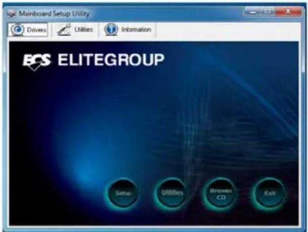
text_image
Mainboard Setup Utility Drivers Utilities Information ECS ELITEGROUP Setup Utilities Browse CD Exit* For reference only

If the opening screen does not appear; double-click the file "setup.exe" in the root directory.
Drivers
| Setup | Click the Setup button to run the software installation program. Select from the menu which software you want to install. |
| Utilities | Click the Utilities button to display the application software and other software utilities that are available on the disk. Select the software you want to install then follow installation procedure. |
| Browse CD | The Browse CD button is the standard Windows command that allows you to open Windows Explorer and show the contents of the support disk.Before installing the software from Windows Explorer, look for a file named README.TXT or something similar. This file may contain important information to help you install the software correctly.Some software is installed in separate folders for different operating systems.In installing the software, execute a file named SETUP.EXE by double-clicking the file and then following the instructions on the screen. |
| Exit | The EXIT button closes the Auto Setup window. |
Utilities
Lists the software utilities that are available on the disk.
Information
Displays the path for all software and drivers available on the disk.
Running Setup
Follow these instructions to install device drivers and software for the motherboard:
- Click Setup. The installation program begins:

text_image
HDC-12 AutoSetup Program Mainboard ID Auto Setup Package software Version 2.00.0011 Welcome to the InstallShield Wizard for AutoSetup The InstallShield Wizard will install AutoSetup on your computer. To continue, click Next. Next > Cancel
The following screens are examples only. The screens and driver lists will be different according to the motherboard you are installing.
The motherboard identification is located in the upper left-hand corner.
2. Click Next. The following screen appears:
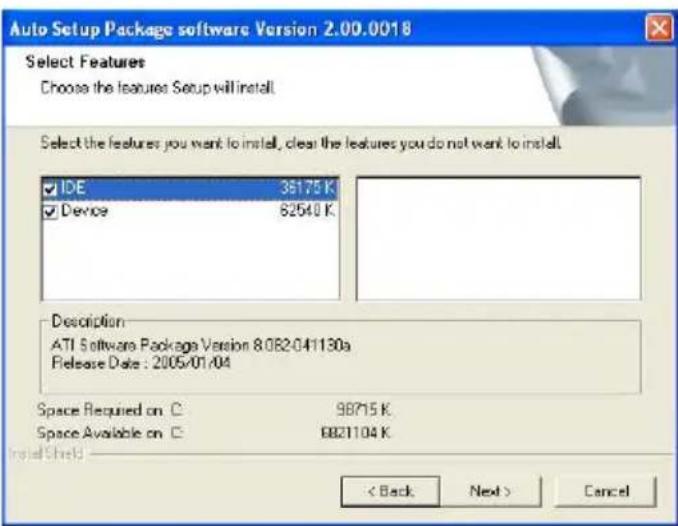
text_image
Auto Setup Package software Version 2.00.0018 Select Features Choose the features Setup will install. Select the features you want to install, clear the features you do not want to install. IDE 36175 K Device 62540 K Description ATI Software Package Version 8.082.041130a Release Date : 2005/01/04 Space Required on C 98715 K Space Available on C 6821104 K Install Shield < Back Next > Cancel-
Check the box next to the items you want to install. The default options are recommended.
-
Click Next run the Installation Wizard. An item installation screen appears:
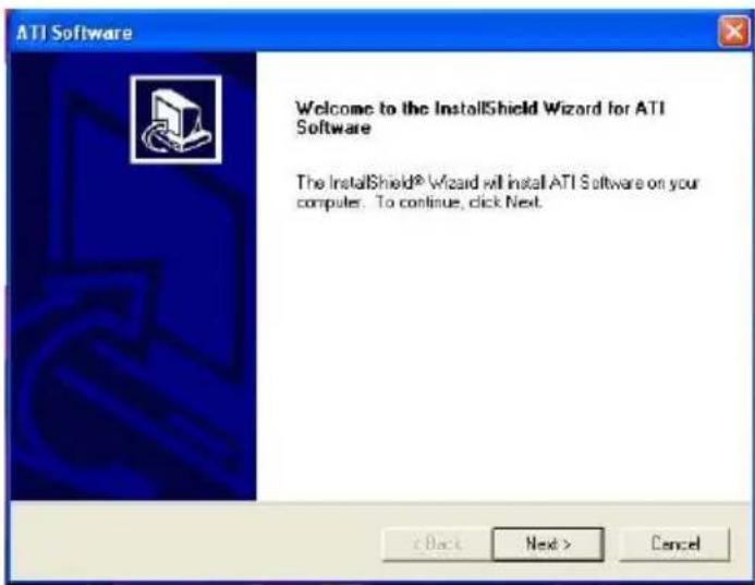
text_image
ATI Software Welcome to the InstallShield Wizard for ATI Software The InstallShield® Wizard will install ATI Software on your computer. To continue, click Next.- Follow the instructions on the screen to install the items.

Drivers and software are automatically installed in sequence. Follow the onscreen instructions, confirm commands and allow the computer to restart a few times to complete the installation.

Windows Vista/7 will appear below UAC (User Account Control) message after the system restart. You must select "Allow" to install the next driver. Continue this process to complete the drivers installation.

text_image
User Account Control An unidentified program wants access to your computer Don't run the program unless you know where it's from or you've used it before. ChPrio.exe Unidentified Publisher Cancel I don't know where this program is from or what it's for. All I trust this program. I know where it's from or I've used it before. Details User Account Control helps stop unauthorized changes to your computer.Manual Installation
Insert the disk in the DVD-ROM/CD-ROM drive and locate the PATH.DOC file in the root directory. This file contains the information needed to locate the drivers for your motherboard.
Look for the chipset and motherboard model; then browse to the directory and path to begin installing the drivers. Most drivers have a setup program (SETUP.EXE) that automatically detects your operating system before installation. Other drivers have the setup program located in the operating system subfolder.
If the driver you want to install does not have a setup program, browse to the operating system subfolder and locate the readme text file (README.TXT or README.DOC) for information on installing the driver or software for your operating system.
Utility Software Reference
All the utility software available from this page is Windows compliant. They are provided only for the convenience of the customer. The following software is furnished under license and may only be used or copied in accordance with the terms of the license.

These software(s) are subject to change at anytime without prior notice. Please refer to the support disk for available software.
Introduction
eJIFFY is a fast boot program under Linux. Instead of waiting Windows O.S to start execution, eJIFFY is ready to provide users the instant enjoyment on web browsing, photo review and online chat just within several seconds after boot up.

text_image
eJIFFY ECS ELITEGROUP Thu Aug 13 12:18 AMNote: eJIFFY is ECS optional feature utility corresponding to the DVD activation and BIOS setup. Please check the hard copy user's guide or product color-box to see if the model has embedded eJIFFY feature. (eJIFFY icon on color-box

Version: 6.0

Note: The eJIFFY function is optional, basing on the different CPU using on the motherboard, please take the actual product for the standard.
Installation and BIOS Setup
DVD Activation
Finish the DVD utility setup, and then set the BIOS to complete eJIFFY activation.
- Insert ECS software utility DVD and enter below "Utilities" screen. Click eJIFFY feature item to install.

text_image
Mainboard Setup Utility Drivers Utilities Information Utilities Adobe Reader eBLU eDLU eJIFFY eSF Select utility & Click to install... 1 / 2 >- Follow the onscreen instructions to finish eJIFFY setup.
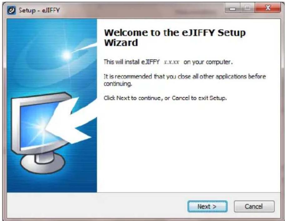
text_image
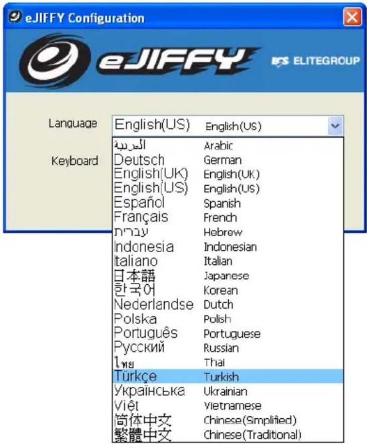
Setup - eJIFFY Welcome to the eJIFFY Setup Wizard This will install eJIFFY x.x.xx on your computer. It is recommended that you close all other applications before continuing. Click Next to continue, or Cancel to exit Setup. Next > Cancel- After setting up eJIFFY under Windows, you can switch eJIFFY display/keyboard language from English to your local language. The changes will be applied after rebooting.
text_image
eJIFFY Configuration eJIFFY ELITEGROUP Language Keyboard English(US) English(US) العربية Deutsch English(UK) English(UK) English(US) English(US) Español Spanish Français French الله Indonesia Hebrew Italiano Indonesian 日本語 Italian 한국어 Japanese Nederlandse Korean Polska Dutch Português Polish Русский Portuguese Russian الله Thai Türkçe Turkish Українська Ukrainian Viêt Vietnamese 简体中文 Chinese(Simplified) 繁體中文 Chinese(Traditional)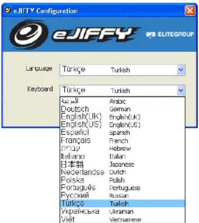
text_image
eJIFFY Configuration eJIFFY ELITEGROUP Language Türkçe Turkish Keyboard Türkçe Turkish الله Arabic Deutsch German English(UK) English(UK) English(US) English(US) Español Spanish Français French الله Hebrew Italiano Italian 日本語 Japanese Nederlandse Dutch Polska Polish Português Portuguese Русский Russian Türkçe Turkish Українська Ukrainian Viêt VietnameseNote: The keyboard language selection list offers several more regional keyboard setups to switch with the default English typing. Please refer to the usage FAQ for more tips.
- Restart your computer after eJIFFY installation. Press
or click the BIOS Setup button on the post screen to enter the BIOS setup page after boot up.

text_image
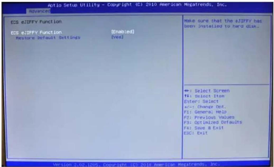
Legacy OpROM Support Launch PXE OpROM [Disabled] Launch Storage OpROM [Enabled] ▶ LAN Configuration ▶ ECS eJIFFY Function ▶ PC Health Status ▶ Power Management Setup ▶ ACPI Settings ▶ CPU Configuration ▶ SATA Configuration ▶ USB Configuration ▶ Trusted Computing Make sure that the eJIFFY has been installed to hard disk. +: Select Screen F1: Select Item Enter: Select +/-: Change Opt. F1: General Help F2: Previous Values F3: Optimized Defaults F4: Save & Exit C30: Exit Version 2.02.1205. Copyright (C) 2010 American Megatrends, Inc.- And then enter the Advanced Setup page to enable the item ECS eJIFFY Function. Press F4 to save the configuration and exit. Restart your computer.
text_image
Aptio Setup Utility - Copyright (C) 2010 American Megatrends, Inc. Advanced ECS eJIFFY Function ECS eJIFFY Function [Enabled] Restore Default Settings [Yes] Make sure that the eJIFFY has been installed to hard disk. +: Select Screen F1: Select Item Enter: Select +/-: Change Opt. F1: General Help F2: Previous Values F3: Optimized Defaults F4: Save & Exit ESC: Exit Version 2.02.1205. Copyright (C) 2010 American Megatrends, Inc.Note: 1. eJIFFY is available in SATA/IDE/AHCI mode. It does not support RAID configuration and the onboard 34-pin floppy drives.
- Please refer to ECS website for new eJIFFY application updates.
Entering eJIFFY
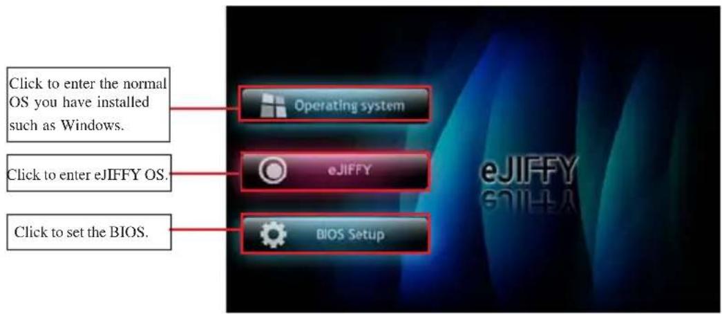
The post screen appears within several seconds after boot up and it has three buttons
text_image
Click to enter the normal OS you have installed such as Windows. Click to enter eJIFFY OS. Click to set the BIOS.If you click eJIFFY, the following screen will appear. And If you make no choice it will enter the normal OS automatically after ten seconds.

text_image
eJIFFY ECS ELITEGROUP USA Thu Aug 13 12:18 AMFeature Icons
The following illustration shows the main feature icons that cJIFFY provides on the menu.

text_image
USA Thu Aug 13 12:20 AM
eWeb: Firefox for web browsing/webmail and watching flash video.

ePix: Photo viewing.

ePal: On-line chat tool to use the most popular IMs in the world. (MSN, ICQ, AIM, etc.)

Shows ePal on-line connection status.

Shut Down/Restart: Ends your session and turns off the computer./Ends your session and restart the computer..

Shows the network connection status.

Click once to connect the storage disk to your computer. Click for the second time to remove your storage disk safely. (please refer to the FAQ for more usage information.)

Language Control Panel

Switch Keyboard Languages

Allows you to adjust the sound volume level from mute to the max
Usage FAQ

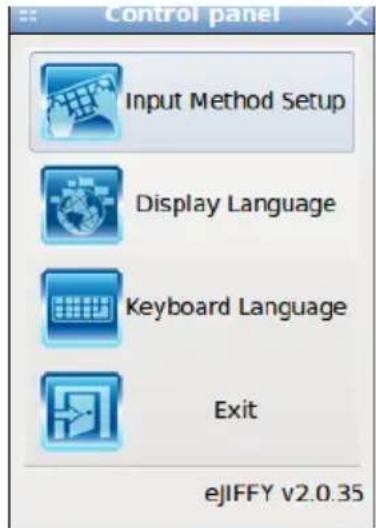
Language Control Panel: Besides setting English as the default interface, eJIFFY offers multi-language displays and keyboard settings for language-switch. Open the language control panel to select a preferable language setting.
Keyboard Language Setup
Step1. Click

to open the language control panel.
text_image
Control panel Input Method Setup Display Language Keyboard Language Exit eJIFFY v2.0.35Step 2: Click "Keyboard Language" icon

to open the keyboard selection
list, which offers several regional keyboard settings besides default English keyboard.
Step 3: Click the selected keyboard language (e.g. English(US)) and press "OK".

text_image
Keyboard language English (US) Cancel OK Arabic (土耳其) German (Deutsch) English (UK) English (US) Spanish (Español) French (Français) Hebrew (İnayı) Italian (Italiano) Japanese (日本語) Dutch (Nederlandse) Polish (Polska) Portuguese (Português) Russian (Русский) Turkish (Türkçe) Ukrainian (Українська) Vietnamese (Việt)Click

to enable all possible language inputs you want to apply, and click
“Apply”:

text_image
SCIM Input Method Setup FrontEnd Global Setup IMEngine Global Setup Anthy Chewing Smart Pinyin Generic Table Panel GTK The installed input method services: Name Enable Hotkeys Filters Japanese ✓ Korean ✓ Russian ✓ Thai ✓ Chinese (simplified) ✓ Chinese (traditional) ✓ Other ✓ Expand Collapse Enable All Disable All Select Filters Edit Hotkeys Bevert Apply Quit OK You can enable/disable input methods and set hotkeys for input methods here.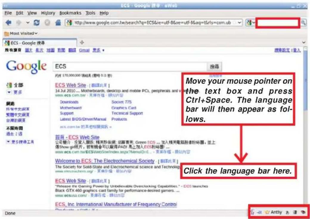
text_image
ECS - Google 搜索 - eWeb File Edit View History Bookmarks Tools Help http://www.google.com.tw/search?q=ECS&ie=utf-8&oe=utf-8&aq=t&rls=com.ub Most Visited ECS - Google 搜寻 Google 全部 更多 網路 所有中文網頁 繁體中文網頁 台灣的網頁 不限時間 過去: 週 更多搜尋工具 ECS 搜索 約約 170,000,000 項結果 (需時 0.13 秒) ECS Web Site - [請填此頁] 14 Jul 2010 ... Motherboards, desktop and mobile PCs, peripherals and video www.ecs.com.tw - 見庫存檔 - 領似內容 Downloads Socket 775 Motherboard Graphics Card Support Technical Support Latest BIOS/DriverManual Products ecs.com.tw 对其他相關資訊 - 首頁 - ECS Web Site 公司簡介 - 反發人關節:精異珍体網;招募青光:Green ECS ... 加入精異電腦翻譯粉砕圖,並上傳Show gn照片,就有機會可以贏得PADI 馬上加入ECS粉砕圖... www.ecs.com.tw/ECSWebSiteIndex.aspx?MenuID=0... - 見庫存檔 - 領似內容 Welcome to ECS: The Electrochemical Society - [請填此頁] The Society for Solid-State and Electrochemical science and Technology www.electrochem.org/ - 見庫存檔 - 領似內容 ECS Web Site - [請填此頁] "Release the Gaming Power by Unbelievable Overclocking Capabilities." - ECS launches Black GTX 460 graphics card family for performance-desired gamers ... www.ecsusa.com/ - 見庫存檔 - 領似內容 ECS, Inc. International Manufacturer of Frequency Control Done Move your mouse pointer on the text box and press Ctrl+Space. The language bar will then appear as follows. Click the language bar here.Select your desired language
Japanese - Anthony
Korean
Russian
Thai
Chinese (simplified)
Chinese (traditional)
Other
English/Keyboard
How to change display language?
Open the Language Control Panel and click

to show the display language
list. Check your desired display language. applied after rebooting.

text_image
Display Language English (US) Cancel OK Arabic (ðs,ðll) German (Deutsch) English (UK) English (US) Spanish (Español) French (Français) Hebrew (núyún) Indonesian (Indonesia) Italian (Italiano) Japanese (日本語) Korean (říngkéř) Dutch (Nederlandse) Polish (Polska) Portuguese (Português) Russian (Русский) Thai (Ínsu) Turkish (Türkçe) Ukrainian (українська) Vietnamese (Viêt) Simplified Chinese (简体中文) Traditional Chinese (繁體中文)How to set networking connection?
If you do not have IP shared server(direct link), you can select the icon

and press the right key of your mouse.
-
Show the networking connection status.
-
If you want to set the networking connection, you can press the right key of your mouse to edit it.
Step1 Select the icon

press the right key of your mouse, then select "Edit
Connection..." item.

text_image
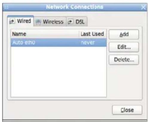
Enable Networking Connection Information Edit Connections... USA Thu Aug 13 12:53 AMStep2 Select the connection you want (eg. Wired) and click “+Add” button.
text_image
Network Connections Wired Wireless DSL Name Last Used Auto echo never Add Edit... Delete... Close
text_image
Editing Auto eth0 Connection name: Auto eth0 Connect automatically Wired 802.1x Security IPv4 Settings IPv6 Settings Method: Automatic (DHCP) Addresses Address Netmask Gateway Add Delete DNS servers: Search domains: DHCP client ID: Routes... Cancel Apply...Types of connections
(1) Wired connection
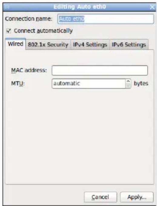
text_image
Editing Auto eth0 Connection name: Auto eth0 Connect automatically Wired 802.1x Security IPv4 Settings IPv6 Settings MAC address: MTU: automatic bytes Cancel Apply...(2) Wireless connection
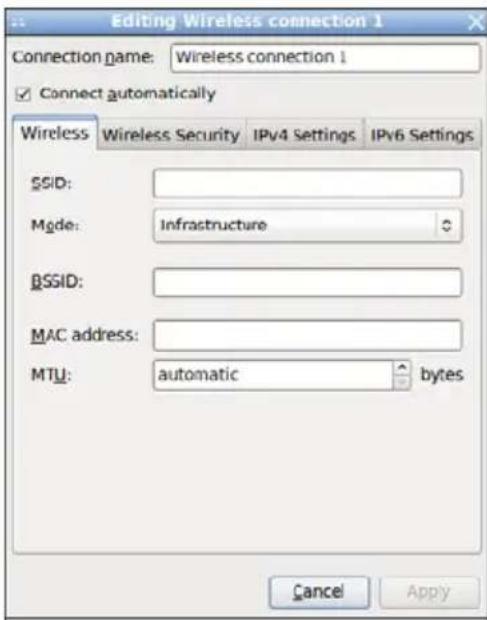
text_image
Editing Wireless connection 1 Connection name: Wireless connection 1 Connect automatically Wireless Wireless Security IPv4 Settings IPv6 Settings SSID: Mode: Infrastructure BSSID: MAC address: MTU: automatic bytes Cancel Apply(3) DSL connection
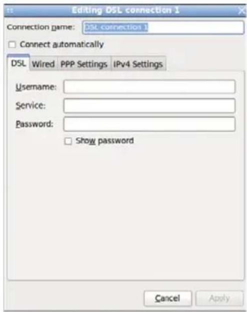
text_image
Editing DSL connection 1 Connection game: DSL connection 1 Connect automatically DSL Wired PPP Settings IPv4 Settings Username: Service: Password: Show password Cancel ApplyNote: Details about eJIFFY please refer to eJIFFY in disk.
★*O□
Start up problems during assembly
After assembling the PC for the first time you may experience some start up problems. Before calling for technical support or returning for warranty, this chapter may help to address some of the common questions using some basic troubleshooting tips.
a) System does not power up and the fans are not running.
- Disassemble the PC to remove the VGA adaptor card, DDR memory, LAN, USB and other peripherals including keyboard and mouse. Leave only the motherboard, CPU with CPU cooler and power supply connected. Turn on again to see if the CPU and power supply fans are running.
- Make sure to remove any unused screws or other metal objects such as screwdrivers from the inside PC case. This is to prevent damage from short circuit.
- Check the CPU FAN connector is connected to the motherboard.
- For Intel platforms check the pins on the CPU socket for damage or bent. A bent pin may cause failure to boot and sometimes permanent damage from short circuit.
- Check the 12V power connector is connected to the motherboard.
- Check that the 12V power & ATX connectors are fully inserted into the motherboard connectors. Make sure the latches of the cable and connector are locked into place.
b) Power is on, fans are running but there is no display
- Make sure the monitor is turned on and the monitor cable is properly connected to the PC.
- Check the VGA adapter card (if applicable) is inserted properly.
- Listen for beep sounds. If you are using internal PC speaker make sure it is connected.
a. continuous 3 short beeps : memory not detected
b. 1 long beep and 8 short beeps : VGA not detected
c) The PC suddenly shuts down while booting up.
-
The CPU may experience overheating so it will shutdown to protect itself. Ensure the CPU fan is working properly.
-
From the BIOS setting, try to disable the Smartfan function to let the fan run at default speed. Doing a Load Optimised Default will also disable the Smartfan.
Start up problems after prolong use
After a prolong period of use your PC may experience start up problems again. This may be caused by breakdown of devices connected to the motherboard such as HDD, CPU fan, etc. The following tips may help to revive the PC or identify the cause of failure.
-
Clear the CMOS values using the CLR_CMOS jumper. Refer to CLR_CMOS jumper in Chapter 2 for Checking Jumper Settings in this user manual. When completed, follow up with a Load Optimised Default in the BIOS setup.
-
Check the CPU cooler fan for dust. Long term accumulation of dust will reduce its effectiveness to cool the processor. Clean the cooler or replace a new one if necessary.
-
Check that the 12V power & ATX connectors are fully inserted into the motherboard connectors. Make sure the latches of the cable and connector are locked into place.
-
Remove the hard drive, optical drive or DDR memory to determine which of these component may be at fault.
Maintenance and care tips
Your computer, like any electrical appliance, requires proper care and maintenance. Here are some basic PC care tips to help prolong the life of the motherboard and keep it running as best as it can.
-
Keep your computer in a well ventilated area. Leave some space between the PC and the wall for sufficient airflow.
-
Keep your computer in a cool dry place. Avoid dusty areas, direct sunlight and areas of high moisture content.
-
Routinely clean the CPU cooler fan to remove dust and hair.
-
In places of hot and humid weather you should turn on your computer once every other week to circulate the air and prevent damage from humidity.
-
Add more memory to your computer if possible. This not only speeds up the system but also reduces the loading of your hard drive to prolong its life span.
-
If possible, ensure the power cord has an earth ground pin directly from the wall outlet. This will reduce voltage fluctuation that may damage sensitive devices.
Basic Troubleshooting Flowchart
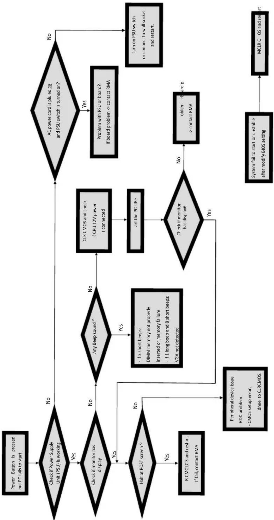
flowchart
graph TD
    A["Power Button is pressed but PC fails to start."] --> B{Check if Power Supply Unit (PSU) is working}
    B -->|Yes| C{Check if monitor has display}
    B -->|No| D{AC power cord is plu ed gg and PSU switch is turned on?}
    C -->|Yes| E{Halt at POST screen ?}
    C -->|No| F{Any Beep sound ?}
    F -->|Yes| G["R CMOLC S and restart. If fail, contact RMA"]
    F -->|No| H{Check if monitor has display6}
    H -->|Yes| I["Peripheral device issue - HDD problem.<br>- CMOS setup error, dnee to CLRCMOS."]
    H -->|No| J{If 3 short beeps: DIMM memory not properly inserted or memory failure
- If 1 long beep and 8 short beeps: VGA not detected}
    J --> K{Check if monitor has display6}
    K -->|Yes| L[" peripheral device issue - HDD problem.<br>- CMOS setup error, dnee to CLRCMOS."]
    K -->|No| M["Problem with PSU or board? If board problem --> contact RMA"]
    M --> N{Check if monitor has displayed?}
    N -->|Yes| O["RL CMOS and check if CPU 12V power is connected"]
    N -->|No| P{AC power cord is plu ed gg and PSU switch is turned on?}
    P -->|Yes| Q["Turn on PSU switch or connect to wall socket and restart."]
    P -->|No| R["Problem with PSU or board? If board problem --> contact RMA"]
    R --> S["oblem r board p --> contact RMA"]
    S --> T["system fail to start or unstable after modify BIOS setting."]
    T --> U["MCLR C OS and restart"]
★*O□