BSWI-D2-N3700 - Motherboard ECS - Free user manual and instructions
Find the device manual for free BSWI-D2-N3700 ECS in PDF.

User questions about BSWI-D2-N3700 ECS
0 question about this device. Answer the ones you know or ask your own.
Ask a new question about this device
Download the instructions for your Motherboard in PDF format for free! Find your manual BSWI-D2-N3700 - ECS and take your electronic device back in hand. On this page are published all the documents necessary for the use of your device. BSWI-D2-N3700 by ECS.
USER MANUAL BSWI-D2-N3700 ECS
text_image
USER GUIDE ECS ELITEGROUP ECS ELITEGROUP BELIEVE TO ACHIEVE BSWI-D2 Version:1.0 40-012-KQ7101 HOMI® ISO-9001 ISO-14001 CE FC © BSWI-D2Preface
Copyright
This publication, including all photographs, illustrations and software, is protected under international copyright laws, with all rights reserved. Neither this manual, nor any of the material contained herein, may be reproduced without written consent of the author.
Version 1.0
Disclaimer
The information in this document is subject to change without notice. The manufacturer makes no representations or warranties with respect to the contents hereof and specifically disclaims any implied warranties of merchantability or fitness for any particular purpose. The manufacturer reserves the right to revise this publication and to make changes from time to time in the content hereof without obligation of the manufacturer to notify any person of such revision or changes.
Trademark Recognition
Microsoft, MS-DOS and Windows are registered trademarks of Microsoft Corp.
MMX, Pentium, Pentium-II, Pentium-III, Celeron are registered trademarks of Intel Corporation.
Other product names used in this manual are the properties of their respective owners and are acknowledged.
Federal Communications Commission (FCC)
This equipment has been tested and found to comply with the limits for a Class B digital device, pursuant to Part 15 of the FCC Rules. These limits are designed to provide reasonable protection against harmful interference in a residential installation. This equipment generates, uses, and can radiate radio frequency energy and, if not installed and used in accordance with the instructions, may cause harmful interference to radio communications. However, there is no guarantee that interference will not occur in a particular installation. If this equipment does cause harmful interference to radio or television reception, which can be determined by turning the equipment off and on, the user is encouraged to try to correct the interference by one or more of the following measures:
•Reorient or relocate the receiving antenna
- Increase the separation between the equipment and the receiver
- Connect the equipment onto an outlet on a circuit different from that to which the receiver is connected
- Consult the dealer or an experienced radio/TV technician for help
Shielded interconnect cables and a shielded AC power cable must be employed with this equipment to ensure compliance with the pertinent RF emission limits governing this device. Changes or modifications not expressly approved by the system's manufacturer could void the user's authority to operate the equipment.
Declaration of Conformity
This device complies with part 15 of the FCC rules. Operation is subject to the following conditions:
•This device may not cause harmful interference.
- This device must accept any interference received, including interference that may cause undesired operation.
This device is in conformity with the following EC/EMC directives:
☐ EN 55022 Limits and methods of measurement of radio disturbance characteristics of information technology equipment
☐ EN 61000-3-2 Disturbances in supply systems caused
☐ EN 61000-3-3 Disturbances in supply systems caused by household appliances and similar electrical equipment “Voltage fluctuations”
☐ EN 55024 Information technology equipment-Immunity characteristics-Limits and methods of measurement
☐ EN 60950 Safety for information technology equipment including electrical business equipment
□ CE marking CE
Canadian Department of Communications
This class B digital apparatus meets all requirements of the Canadian Interference-causing Equipment Regulations.
The manual consists of the following:
Chapter 1 Describes features of the ➔ page 1 Introducing the Motherboard motherboard.
Chapter 2 Describes installation of page 7 Installing the Motherboard motherboard components.
Chapter 3 Using BIOS Provides information on us- → page 21 ing the BIOS Setup Utility.
Chapter 4 Describes the motherboard page 49 Using the Motherboard Software software.
Chapter 5 Trouble Shooting Provides basic trouble shoot-→ page 53 ing tips.
Preface i
Chapter 1 1
Introducing the Motherboard 1
Introduction....1
Pakage Contents....1
Specifications....2
Motherboard Components......4
I/O Ports....6
Chapter 2 7
Installing the Motherboard 7
Safety Precautions....7
Installing the Motherboard in a Chassis....7
Checking Jumper Settings....8
Installing Hardware....9
Installing Memory Modules....9
Connecting Optional Devices....10
Installing a SATA Hard Drive....16
Connecting Case Components....17
Chapter 3 21
Using BIOS 21
About the Setup Utility....21
The Standard Configuration....21
Entering the Setup Utility....21
Resetting the Default CMOS Values....22
Using BIOS....22
BIOS Navigation Keys....23
Main Menu....24
Advanced Menu....24
Chipset Menu....40
M.I.B X (MB Intelligent BIOS X) Menu....42
Boot Menu....43
Security Menu....44
Exit Menu....46
Updating the BIOS....47
Chapter 4 49
Using the Motherboard Software 49
Auto-installing under Windows 7/8.1/10....49
Running Setup....49
Manual Installation....51
ECS Utility Software (Intelligent EZ Utility) (Optional)......51
Chapter 5 53
Trouble Shooting 53
Start up problems during assembly....53
Start up problems after prolong use....54
Maintenance and care tips....54
Basic Troubleshooting Flowchart....55
Chapter 1
Introducing the Motherboard
Introduction
Thank you for choosing the BSWI-D2 motherboard. This motherboard is a high performance, enhanced function. This motherboard has onboard Intel® Braswell SoC for high-end business or personal desktop markets.
It supports up to 8 GB of system memory with single channel DDR3L 1600MHz SO-DIMM.
It implements an EHCI (Enhanced Host Controller Interface) compliant interface that provides four USB 2.0 ports (two USB 2.0 ports at the rear panel and one 2*5-pin USB 2.0 header supports additional two USB 2.0 ports) and four USB 3.0 ports (two USB 3.0 ports at the rear panel and one USB 3.0 header supports additional two USB 3.0 ports).
The motherboard is equipped with advanced full set of I/O ports in the rear panel, including one PS/2 Keyboard & PS/2 Mouse connectors, one D-sub (VGA) port, one COM port, one HDMI port, two USB 3.0 ports, two USB 2.0 ports, one RJ45 LAN connector and audio jacks for line-in, line-out and microphone.
In addition, this motherboard supports two SATA 6Gb/s connectors for expansion.
Package Contents
Your motherboard package ships with the following items:
BSWI-D2 Motherboard
□ User Manual
DVD
I/O Shield
2 SATA Cables

Accessories may vary, please refer to actual goods you purchase.
Specifications
| SoC | Onboard Intel® Braswell Pentium QC N3700/Celeron QC N3150/Celeron DC N3050 or other SoCSupports TDP up to 6WNote: Please go to ECS website for the latest CPU support list. |
| Memory | Signal channel DDR3L SO-DIMM memory architecture1 x 204-pin DDR3L SO-DIMM socket supports up to 8 GBSupports DDR3L 1600 MHz DDR3 SDRAMNote: Please go to ECS website for the latest Memory support list. |
| Storage | Supported by Intel® Braswell SoC- 2 x Serial ATA 6Gb/s devices |
| Audio | Realtek ALC662 6-CH HD Audio CODEC- 6 Channel High Definition Audio Codec- Compliant with HD audio specification |
| LAN • Realtek RTL8111H Gigabit LAN | |
| Rear Panel I/O | 1 x PS/2 Keyboard & PS/2 Mouse connectors1 x D-sub (VGA) port1 x COM port1 x HDMI port2 x USB 3.0 ports1 x RJ45 LAN connector2 x USB 2.0 ports1 x Audio port (1 x line-in, 1 x line-out, 1 x Microphone) |
| Internal I/OConnectors & Headers | 1 x 24-pin ATX Power Supply connector1 x 4-pin CPU_FAN connector1 x 4-pin SYS_FAN connector1 x 2*5-pin USB 2.0 header supports additional two USB 2.0 ports2 x Serial ATA 6Gb/s connectors1 x BZ1 x Front Panel switch/LED header1 x Front Panel audio header1 x Clear CMOS jumper1 x Case open header1 x Parallel port header (LPT)1 x TPM header1 x EMMC header1 x USB 3.0 header1 x COM header |
| System BIOS | • AMI BIOS with 64Mb SPI Flash ROM- Supports Plug and Play- Supports ACPI & DMI- Supports STR (S3) /STD (S4)- Supports Hardware monitor- Audio, LAN, can be disabled in BIOS- F7 hot key for boot up devices option- Supports PgUp clear CMOS Hotkey (Has PS2 KB Model only) |
| Ap/ Bundled Software Support | • Supports eBLU* ^1 /eDLU/eSF• 3rd Party Bundled Software: Cyberlink Media Suite* ^2 Note: *Microsoft .NET Framework 3.5 is required.* ^2 Free bundle software is including ECS DVD: Cyberlink Media Suite. |
| Form Factor | • Mini ITX Size, 170mm x 170mm |
Motherboard Components
*BSWI-D2-N3700/BSWI-D2-N3150/BSWI-D2-N3050 MB image

text_image
PSKBM VGA COM1 HDMI USB3K SATA2 SATA1 USB LAN AUDIO F_AUDIO F_USB2 USB3F RZ WTR-120.5 CLR CMOSL CASE CPU_FAN ATX_POWER BSW-02 COM2 ② ③ ④ ⑤ ⑥ ⑦ ⑧ ⑨ ⑩ ⑪ ⑫ ⑬ ⑭ ⑮Table of Motherboard Components (BSWI-D2-N3700/BSWI-D2-N3150/BSWI-D2-N3050)
| LABEL | COMPONENT |
| 1. CPU_FAN | 4-pin CPU cooling fan connector |
| 2. COM2 | Onboard serial port header |
| 3. DIMM1 | 204-pin DDR3L SDRAM SO-DIMIM |
| 4. TPM | Trusted platform module header |
| 5. LPT | Onboard parallel port header |
| 6. CLR_CMOS | Clear CMOS jumper |
| 7. F_PANEL | Front panel switch/LED header |
| 8. CASE | Case open header |
| 9. BZ | Buzzer |
| 10. USB3F | Front panel USB 3.0 header |
| 11. F_USB2 | 2*5 PIN Front USB 2.0 header |
| 12. F_AUDIO | Front panel audio header |
| 13. EMIVC | EMIVCheader |
| 14. SATA1~2 | Serial ATA 6Gb/s connectors |
| 15. SYS_FAN | 4-pin system cooling fan connector |
| 16. ATX_POWER | Standard 24-pin ATX Power connector |
I/O Ports

text_image
Diagram of computer ports with numbered labels pointing to different electronic devices- PS/2 Mouse (green)
Use the upper PS/2 port to connect a PS/2 mouse.
- PS/2 Keyboard (purple)
Use the lower PS/2 port to connect a PS/2 keyboard.
- VGA Port
Connect your monitor to the VGA port.
- COM1 Port
Use the COM1 port to connect the serial devices such as mice or fax/modems.
- HDMI Port
You can connect the display device to the HDMI port.
- USB 3.0 Ports
Use the USB 3.0 port to connect USB 3.0 device.
- LAN Port
Connect an RJ-45 jack to the LAN port to connect your computer to the Network.
| LAN LED Status | Description | |
| Activity LED | OFF No data | |
| Orange blinking | Active | |
| Link LED | OFF No link | |
| Green Link |
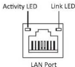
text_image
Activity LED Link LED LAN Port- USB 2.0 Ports
Use the USB 2.0 ports to connect USB 2.0 devices.
- Line-in (blue)
It can be connected to an external CD/DVD player, Tape player or other audio devices for audio input.
- Line-out (green)
It is used to connect to speakers or headphones.
- Microphone (pink)
It is used to connect to a microphone.
Chapter 2 Installing the Motherboard
2-1. Safety Precautions
Follow these safety precautions when installing the motherboard:
- Wear a grounding strap attached to a grounded device to avoid damage from static electricity.
- Discharge static electricity by touching the metal case of a safely grounded object before working on the motherboard.
- Leave components in the static-proof bags.
• Always remove the AC power by unplugging the power cord from the power outlet before installing or removing the motherboard or other hardware components.
2-2. Installing the motherboard in a Chassis
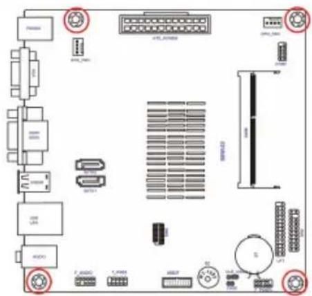
This motherboard carries a Mini ITX form factor of 170 x 170 mm. Choose a chassis that accommodates this form factor. Make sure that the I/O template in the chassis matches the I/O ports installed on the rear edge of the motherboard. Most system chassis have mounting brackets installed in the chassis, which corresponds to the holes in the motherboard. Place the motherboard over the mounting brackets and secure the motherboard onto the mounting brackets with screws.
text_image
Technical diagram of an electronic circuit board layout with labeled components and connectors
Do not over-tighten the screws as this can stress the motherboard.
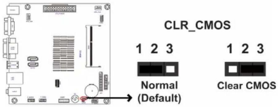
2-3. Checking Jumper Settings
The following illustration shows the location of the motherboard jumpers. Pin 1 is labeled.
text_image
CLR_CMOS 1 2 3 Normal (Default) 1 2 3 Clear CMOS
To avoid the system instability after clearing CMOS, we recommend users to enter the main BIOS setting page to "Load Default Settings" and then "Save and Exit Setup".
2-4. Installing Hardware
2-4-1. Installing Memory Modules
- This motherboard accommodates one memory module. It can support one 204-pin DDR3L 1600 MHz. - Do not remove any memory module from its antistatic packaging until you are ready to install it on the motherboard. Handle the modules only by their edges. Do not touch the components or metal parts. Always wear a grounding strap when you handle the modules.
- You must install one module in the slot. Total memory capacity is 8 GB.
- Refer to the following to install the memory modules.
Install the DIMM module into the slot and press it firmly down until it seats correctly. Check that the cutouts on the DIMM module edge connector match the notches in the DIMM slot.

text_image
DIMM12-4-2. Connecting Optional Devices
Refer to the following for information on connecting the motherboard's optional devices:

text_image
Labeled diagram of an electronic device module with numbered components and connectors| No. Components No. Components | |||
| 1 | C | O | M 2 |
| 2 | T | P | M 7 |
| 3 LPT 8 EMMC | |||
| 4 | CASE | 9 | SATA_1~2 |
| 5 | USB3F | ~ | ~ |
1. COM2: Onboard Serial Port Header
Connect serial port extension brackets to these headers to add serial ports to your system.

text_image
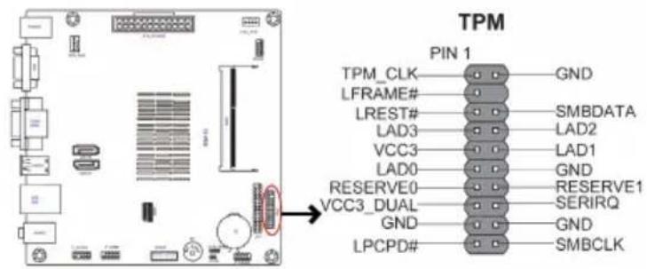
Clear to Send Data Set Ready Data Terminal Ready Serial Input Ring Indicator Request to Send Ground Serial Output Data Carrier Detect PIN 1 COM22. TPM: Trusted Platform Module header
Tursted Platform Module (TPM) is a published specification detailing a micro controller that can store secured information, and implementations of that specification.
This header can be used to connect to the printer, scanner or other devices.

text_image
SLCT Ground Ground Ground Ground Ground Ground Ground SLCT INIT ERROR AFD PE BUSK ACK PD7 PD6 PD5 PD4 PD3 PD2 PD1 PD0 STROBE PIN 1 LPT4. CASE: Chassis Intrusion Detect Header
This detects if the chassis cover has been removed. This function needs a chassis equipped with intrusion detection switch and needs to be enabled in BIOS.

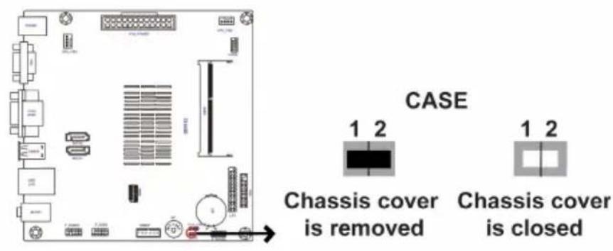
text_image
CASE 1 2 Chassis cover is removed 1 2 Chassis cover is closed5. USB3F: Front Panel USB 3.0 header
This Motherboard implements one USB 3.0 header supporting 2 extra front USB 3.0 ports, which delivers 5Gb/s transfer rate.

text_image
USB3 ICC Port1 SuperSpeed Rx- USB3 ICC Port1 SuperSpeed Rx+ Ground USB3 ICC Port1 SuperSpeed Tx- USB3 ICC Port1 SuperSpeed Tx+ Ground USB3 ICC Port1 D- USB3 ICC Port1 D+ Not Connected PIN 1 USB3 ICC Port2 D+ USB3 ICC Port2 D- Ground USB3 ICC Port2 SuperSpeed Tx+ USB3 ICC Port2 SuperSpeed Tx- Ground USB3 ICC Port2 SuperSpeed Rx+ USB3 ICC Port2 SuperSpeed Rx- Front Panel USB Power USB3F
Please make sure that the USB cable has the same pin assignment as indicated above. A different pin assignment may cause damage or system hang-up.
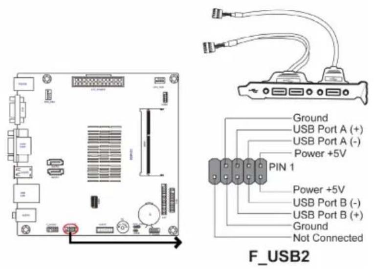
6. F\_USB2: 2\*5-pin Front Panel USB 2.0 Header
The motherboard has one 2*5-pin USB 2.0 header supporting two USB 2.0 ports. Additionally, some computer cases have USB 2.0 ports at the front of the case. If you have this kind of case, use auxiliary USB 2.0 connector to connect the front-mounted ports to the motherboard.
text_image
Ground USB Port A (+) USB Port A (-) Power +5V PIN 1 Power +5V USB Port B (-) USB Port B (+) Ground Not Connected F_USB2
Please make sure that the USB cable has the same pin assignment as indicated above. A different pin assignment may cause damage or system hang-up.
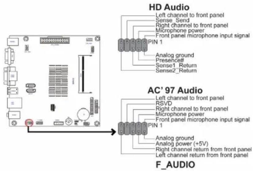
7. F\_AUDIO: Front Panel Audio Header
The front panel audio header allows the user to install auxiliary front-oriented microphone and line-out ports for easier access. This header supports HD audio by default. If you want connect an AC' 97 front panel audio to HD onboard headers, please set as below picture.
text_image
HD Audio Left channel to front panel Sense_Send Right channel to front panel Microphone power Front panel microphone input signal PIN 1 Analog ground Presence# Sense1_Return Sense2_Return AC' 97 Audio Left channel to front panel RSVD Right channel to front panel Microphone power Front panel microphone input signal PIN 1 Analog ground Analog power (+5V) Right channel return from front panel Left channel return from front panel F_AUDIOAC' 97 Audio Configuration: To enable the front panel audio connector to support AC97 Audio mode.
If you use AC' 97 Front Panel, please tick off the option of "Disabled Front Panel Detect". If you use HD Audio Front Panel, please don't tick off "Disabled Front Panel Detect".

text_image
Realtek HD Audio Manager NEW Main Volume L R Set Default Description Speaker Configuration Sound Effects Power Connections Default Format Speaker Configuration: Stress Connector Settings Driver Feed panel jack deflection OK Cancel Full-range speakers Microsoft Word and Right Standard speakers Virtual Demand REALTEK* For reference only
If you use AC' 97 Front Panel, please don't tick off "Using Front Jack Detect". If you use HD Audio Front Panel, please tick off the option of "Using Front Jack Detect".
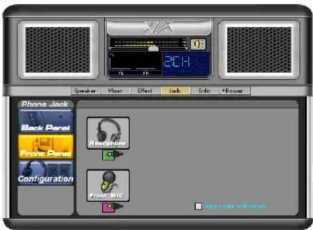
text_image
Phone Jack Back Panel Front Panel Configuration Headphone Front MIC 2:14 Speaker Mixer Effect Jack Info *Power Line Front Audio Drive* For reference only
8. EMMC Header

text_image
EMMC GND -MMC1_CMD GND -MMC1_CLK GND -MMC1_D3 +V1P8S -MMC1_D0 GND -MMC1_D4 GND -MMC1_D1 VCC3 -MMC1_D5 GND -MMC1_D2 GND -MMC1_D6 PIN 1 MMC1_D7
The EMMC-BSW-32G card is not included in the package, you can buy it separately and install.
9. SATA1\~2: Serial ATA Connectors
SATA 1\~2 connectors support the Serial ATA 6Gb/s device, simpler disk drive cabling and easier PC assembly. It eliminates limitations of the current Parallel ATA interface. But maintains register compatibility and software compatibility with Parallel ATA.
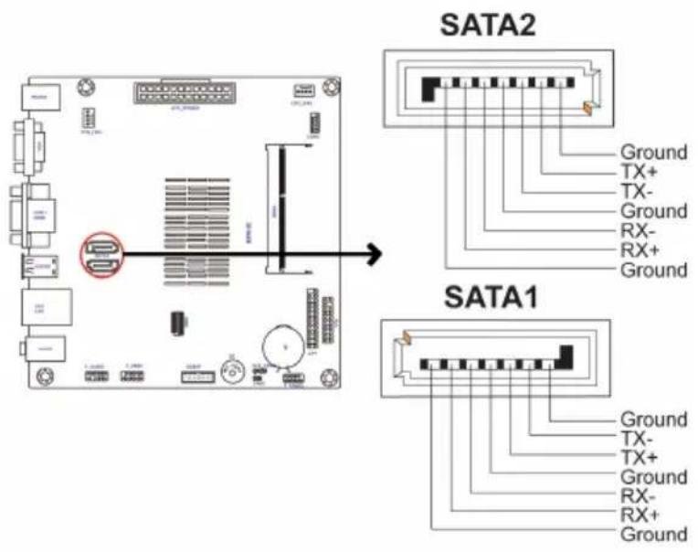
text_image
SATA2 Ground TX+ TX- Ground RX- RX+ Ground SATA1 Ground TX- TX+ Ground RX- RX+ Ground2-4-3. Installing a SATA Hard Drive
This section describes how to install a SATA Hard Drive.
About SATA Connectors
Your motherboard features two SATA connectors supporting a total of two drives. SATA refers to Serial ATA (Advanced Technology Attachment) is the standard interface for the IDE hard drives which are currently used in most PCs. These connectors are well designed and will only fit in one orientation. Locate the SATA connectors on the motherboard and follow the illustration below to install the SATA hard drives.
Installing Serial ATA Hard Drives
To install the Serial ATA (SATA) hard drives, use the SATA cable that supports the Serial ATA protocol. This SATA cable comes with a SATA power cable. You can connect either end of the SATA cable to the SATA hard drive or the connector on the motherboard.
Refer to the illustration below for proper installation:
1 Attach either cable end to the connector on the motherboard.
2 Attach the other cable end to the SATA hard drive.
3 Attach the SATA power cable to the SATA hard drive and connect the other end to the power supply.
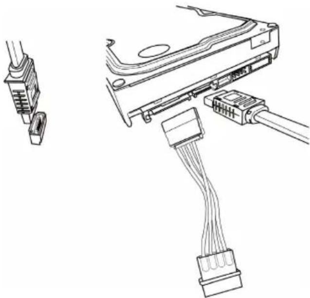
natural_image
Technical line drawing of a hard disk drive with connectors and cable (no text or symbols)* For reference only
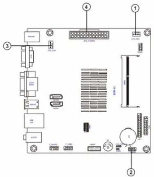
2-4-4. Connecting Case Components
After you have installed the motherboard into a case, you can begin connecting the motherboard components. Refer to the following:
text_image
Labeled diagram of an electronic device rear panel showing ports, connectors, and internal components with numbered annotations.| No. Components No. Components | |||
| 1 CPU_FAN 3 SYS_FAN | |||
| 2 F PANEL 4 ATX_POWER | |||
1 & 3. CPU\_FAN (CPU Cooling FAN Connector) & SYS\_FAN (System Cooling FAN Connector)
Connect the CPU cooling fan cable to CPU_FAN.
Connect the system cooling fan connector to SYS_FAN.

text_image
PWM Sensor Power +12V System Ground CPU_FAN PWM Sensor Power +12V System Ground SYS_FAN
Users please note that the fan connector supports the CPU cooling fan of 1.1A \~ 2.2A (26.4W max) at +12V.
2. F\_PANEL: Front Panel Header
The front panel header (F_PANEL) provides a standard set of switch and LED headers commonly found on ATX or Micro ATX cases. Refer to the table below for information:

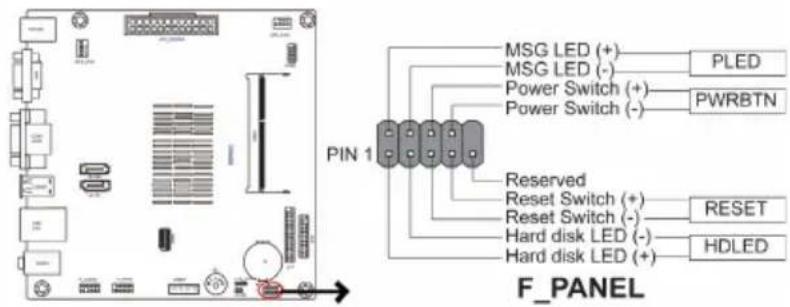
text_image
MSG LED (+) — PLED MSG LED (-) — Power Switch (+) — PWRBTN Power Switch (-) — Power Switch (-) PEN 1 Reserved Reset Switch (+) — RESET Reset Switch (-) — Hard disk LED (-) — HDLED Hard disk LED (+) — F_PANELHard Drive Activity LED
Connecting pins 1 and 3 to a front panel mounted LED provides visual indication that data is being read from or written to the hard drive. For the LED to function properly, an IDE drive should be connected to the onboard IDE interface. The LED will also show activity for devices connected to the SCSI (hard drive activity LED) connector.
Power/Sleep/Message waiting LED
Connecting pins 2 and 4 to a single or dual-color, front panel mounted LED provides power on/off, sleep, and message waiting indication.
Reset Switch
Supporting the reset function requires connecting pin 5 and 7 to a momentary-contact switch that is normally open. When the switch is closed, the board resets and runs POST.
Power Switch
Supporting the power on/off function requires connecting pins 6 and 8 to a momentary-contact switch that is normally open. The switch should maintain contact for at least 50 ms to signal the power supply to switch on or off. The time requirement is due to internal de-bounce circuitry. After receiving a power on/off signal, at least two seconds elapses before the power supply recognizes another on/off signal.
4. ATX\_POWER (ATX 24-pin Power Connector)
Connect the standard power supply connector to ATX_POWER.
text_image
ATX_POWER Ground +5V +5V +5V -5V Ground Ground Ground PS_ON Ground -12V +3.3V PIN 1 +3.3V +3.3V Ground +5V Ground +5V Ground PWRGD +5VSB +12V +12V +3.3V
Connecting 24-pin power cable
The ATX 24-pin connector allows you to connect to ATX v2.x power supply.

natural_image
Diagram showing two mechanical components with a downward arrow indicating a process or assembly (no text or symbols present)With ATX v2.x power supply, users please note that when installing 24-pin power cable, the latches of power cable and the ATX match perfectly.
24-pin power cable
Memo
Chapter 2
Chapter 3
Using BIOS
About the Setup Utility
The computer uses the latest “American Megatrends Inc.” BIOS with support for Windows Plug and Play. The CMOS chip on the motherboard contains the ROM setup instructions for configuring the motherboard BIOS.
The BIOS (Basic Input and Output System) Setup Utility displays the system's configuration status and provides you with options to set system parameters. The parameters are stored in battery-backed-up CMOS RAM that saves this information when the power is turned off. When the system is turned back on, the system is configured with the values you stored in CMOS.
The BIOS Setup Utility enables you to configure:
- Hard drives, diskette drives and peripherals
• Video display type and display options - Password protection from unauthorized use
• Power Management features
The settings made in the Setup Utility affect how the computer performs. Before using the Setup Utility, ensure that you understand the Setup Utility options.
This chapter provides explanations for Setup Utility options.
The Standard Configuration
A standard configuration has already been set in the Setup Utility. However, we recommend that you read this chapter in case you need to make any changes in the future.
This Setup Utility should be used:
- when changing the system configuration
- when a configuration error is detected and you are prompted to make changes to the Setup Utility
- when trying to resolve IRQ conflicts
- when making changes to the Power Management configuration
- when changing the password or making other changes to the Security Setup
Entering the Setup Utility
When you power on the system, BIOS enters the Power-On Self Test (POST) routines. POST is a series of built-in diagnostics performed by the BIOS. After the POST routines are completed, the following message appears:
Press DEL to enter SETUP
Press the delete key to access BIOS Setup Utility.
| Main Advanced Chipset M.I.B X Boot Security Exit | |
| BIOS InformationSystem Language [English]System Date [Tue 07/28/2015]System Time [00:06:28] | Choose the system default language. |
| → ←:Select Screen↑↓ :Select ItemEnter : Select+/- :Change Opt.F1:General HelpF2:Previous ValuesF3:Optimized DefaultsF4:Save & ExitESC:Exit | |
| Version 2.17.1249. Copyright (C) 2015 American Megatrends, Inc. | |
Resetting the Default CMOS Values
When powering on for the first time, the POST screen may show a "CMOS Settings Wrong" message. This standard message will appear following a clear CMOS data at factory by the manufacturer. You simply need to Load Default Settings to reset the default CMOS values.
Note: Changes to system hardware such as different CPU, memories, etc. may also trigger this message.

text_image
American Megatrends BSWI-D2 Release 07/28/2015 Version 2.17.1249. Copyright (C) 2015 American Megatrends, Inc. PressUsing BIOS
When you start the Setup Utility, the main menu appears. The main menu of the Setup Utility displays a list of the options that are available. A highlight indicates which option is currently selected. Use the cursor arrow keys to move the highlight to other options. When an option is highlighted, execute the option by pressing
Some options lead to pop-up dialog boxes that prompt you to verify that you wish to execute that option. Other options lead to dialog boxes that prompt you for information.
Some options (marked with a triangle ▶) lead to submenus that enable you to change the values for the option. Use the cursor arrow keys to scroll through the items in the submenu.
In this manual, default values are enclosed in parenthesis. Submenu items are denoted by a triangle ▶.

The default BIOS setting for this motherboard apply for most conditions with optimum performance. We do not suggest users change the default values in the BIOS setup and take no responsibility to any damage caused by changing the BIOS settings.
BIOS Navigation Keys
The BIOS navigation keys are listed below:
| KEY FUNCTION | |
| ESC | Exits the current menu |
| Scrolls through the items on a menu | |
| +/- Modifies the selected field's values | |
| Enter | Select |
| F1 General Help | |
| F2 Previous Values | |
| F3 Optimized Defaults | |
| F4 Save & Exit | |

For the purpose of better product maintenance, the manufacture reserves the right to change the BIOS items presented in this manual. The BIOS setup screens shown in this chapter are for reference only and may differ from the actual BIOS. Please visit the manufacture's website for updated manual.
Main Menu
When you enter the BIOS Setup program, the main menu appears, giving you an overview of the basic system information. Select an item and press
| Main Advanced Chipset M.I.B X Boot Security Exit | |
| BIOS InformationSystem Language [English]System Date [Tue 07/28/2015]System Time [00:06:28] | Choose the system default language. |
| → ←:Select Screen↑↓ :Select ItemEnter : Select+/- :Change Opt.F1:General HelpF2:Previous ValuesF3:Optimized DefaultsF4:Save & ExitESC:Exit | |
| Version 2.17.1249. Copyright (C) 2015 American Megatrends, Inc. | |
System Language (English)
This item is used to set the language.
System Date & Time
The Date and Time items show the current date and time on the computer. If you are running a Windows OS, these items are automatically updated whenever you make changes to the Windows Date and Time Properties utility.
Advanced Menu
The Advanced menu items allow you to change the settings for the CPU and other system.
| Aptio Setup Utility - Copyright (C) 2015 American Megatrends, Inc.Main Advanced Chipset M.I.B X Boot Security Exit | |
| Power Management SetupPC Health StatusLAN ConfigurationWireless Function ConfigurationACPI SettingsCPU ConfigurationSATA ConfigurationUSB ConfigurationSuper IO ConfigurationPlatform Trust TechnologyTrusted Computing | ACPI Power ManagementConfiguration→ ←:Select Screen↑↓ :Select ItemEnter : Select+/- :Change Opt.F1:General HelpF2:Previous ValuesF3:Optimized DefaultsF4:Save & ExitESC:Exit |
| Version 2.17.1249. Copyright (C) 2015 American Megatrends, Inc. | |
▶Power Management Setup
This page sets up some parameters for system power management operation.
| Aptio Setup Utility - Copyright (C) 2015 American Megatrends, Inc.Main Advanced Chipset M.I.B X Boot Security Exit | |
| Power Management SetupResume By PME [Disabled]Resume By USB [Disabled]Resume By PS2 KB [Disabled]Resume By PS2 MS [Disabled]Resume By RTC Alarm [Disabled]EUP Function [Enabled]Power LED Type [Dual Color LED] | About Resume byPCI/PCI-E/LAN/Ext.USB 3.0 PME |
| → ← :Select Screen↑↓ :Select ItemEnter : Select+/- :Change Opt.F1:General HelpF2:Previous ValuesF3:Optimized DefaultsF4:Save & ExitESC:Exit | |
| Version 2.17.1249. Copyright (C) 2015 American Megatrends, Inc. | |
Resume By PME (Disabled)
The system can be turned off with a software command. If you enable this item, the system can automatically resume if there is an incoming call on the PCI/PCI-E Modem or PCI/PCI-E LAN card. You must use an ATX power supply in order to use this feature. Use this item to do wake-up action if inserting the PCI/PCI-E card.
Resume By USB (Disabled)
This item allows you to enable or disable the USB device wakeup function from S3 mode.
Resume By PS2 KB (Disabled)
This item enables or disables you to allow keyboard activity to awaken the system from power saving mode. The system can be turned off with a software command. If you enable this item, the system can automatically resume at a fixed time based on the system's RTC (realtime clock). Use the items below this one to set the date and time of the wake-up alarm. You must use an ATX power supply in order to use this feature.
Resume By PS2 MS (Disabled)
This item enables or disables you to allow mouse activity to awaken the system from power saving mode.
Resume By RTC Alarm (Disabled)
The system can be turned off with a software command. If you enable this item, the system can automatically resume at a fixed time based on the system's RTC (realtime clock). Use the items below this one to set the date and time of the wake-up alarm. You must use an ATX power supply in order to use this feature.
EUP Function (Enabled)
This item allows user to enable or disable EUP support.
Power LED Type (Dual Color LED)
This item shows the type of the Power LED.
Press
▶PC Health Status
On motherboards support hardware monitoring, this item lets you monitor the paremeters for critical voltages, temperatures and fan speeds.
| Aptio Setup Utility - Copyright (C) 2015 American Megatrends, Inc.Main Advanced Chipset M.I.B X Boot Security Exit | |
| PC Health Status | |
| ►Smart Fan FunctionSoC Temperature 32°CSystem Temperature 32°CCPU Fan Speed 0 RPMSystem Fan Speed 0 RPMCPU Voltage 0.814VDIMM Voltage 1.364V+12V 12.474V+5V 5.027V+3.3V 3.520V | → ←:Select Screen↑↓ :Select ItemEnter : Select+/- :Change Opt.F1:General HelpF2:Previous ValuesF3:Optimized DefaultsF4:Save & ExitESC:Exit |
| Version 2.17.1249. Copyright (C) 2015 American Megatrends, Inc. | |
▶Smart Fan Function
Scroll to this item and press
| Aptio Setup Utility - Copyright (C) 2015 American Megatrends, Inc.Main Advanced Chipset M.I.B X Boot Security Exit | |
| Smart Fan Select [CPU]Smart Fan Mode [Normal]Smart Fan start PWM value 180Smart Fan start PWM TEMP (°C) 45DeltaT 3Smart Fan Slope PWM value 10Fan Full Limit Temp (°C) 52 | Smart Fan Select |
| → ←:Select Screen↑↓ :Select ItemEnter : Select+/- :Change Opt.F1:General HelpF2:Previous ValuesF3:Optimized DefaultsF4:Save & ExitESC:Exit | |
| Version 2.17.1249. Copyright (C) 2015 American Megatrends, Inc. | |
Smart Fan Select (CPU)
This item allows you to change and configure Smart Fans on CPU Fan or System Fan.
Smart Fan Mode (Normal)
This item allows you to select the fan mode (Normal, Quiet, Silent, or Manual) for a better operation environment. If you choose Normal mode, the fan speed will be auto adjusted depending on the CPU temperature. If you choose Quite mode, the fan speed will be auto minimized for quiet environment. If you choose Silent mode, the fan speed will be auto restricted to make system more quietly. If you choose Manual mode, the fan speed will be adjust depending on users' parameters.
Smart Fan start PWM value (180)
This item is used to set the start PWM value of the smart fan.
Smart Fan start PWM TEMP (°C) (45)
This item is used to set the start temperature of the smart fan.
DeltaT (3)
This item specifies the range that controls CPU temperature and keeps it from going so high or so low when smart fan works.
Smart Fan Slope PWM value (10)
This item is used to set the Slope Select PWM of the smart fan.
Fan Full Limit Temp (°C) (52)
This item is used to monitor limit temperature when fan is full speed.
Press
System Component Characteristics
These items display the monitoring of the overall inboard hardware health events, such as System & CPU temperature, CPU & DIMM voltage, CPU & system fan speed,... etc.
- SoC Temperature
- System Temperature
- CPU Fan Speed
- System Fan Speed
- CPU Voltage
- DIMM Voltage
• +12V
• +5V
• +3.3V
Press
▶LAN Configuration
The item in the menu shows the LAN-related information that the BIOS automatically detects.
| Main Advanced Chipset M.I.B X Boot Security Exit | |
| LAN ConfigurationOnboard LAN Controller [Enabled] | Enabled/Disabled Onboard LAN 1 Controller |
| → ←:Select Screen↑↓ :Select ItemEnter : Select+/- :Change Opt.F1:General HelpF2:Previous ValuesF3:Optimized DefaultsF4:Save & ExitESC:Exit | |
| Version 2.17.1249. Copyright (C) 2015 American Megatrends, Inc. | |
Onboard LAN Controller (Enabled)
Use this item to enable or disable the Onboard LAN.
Press
▶ Wireless Function Configuration
The item in the menu shows the Wireless Function Configuration.
| Aptio Setup Utility - Copyright (C) 2015 American Megatrends, Inc.Main Advanced Chipset M.I.B X Boot Security Exit | |
| Wireless Function Configuration | |
| → ←:Select Screen↑↓ :Select ItemEnter : Select+/- :Change Opt.F1:General HelpF2:Previous ValuesF3:Optimized DefaultsF4:Save & ExitESC:Exit | |
| Version 2.17.1249. Copyright (C) 2015 American Megatrends, Inc. | |
▶ACPI Settings
The item in the menu shows the highest ACPI sleep state when the system enters suspend.
| Aptio Setup Utility - Copyright (C) 2015 American Megatrends, Inc.Main Advanced Chipset M.I.B X Boot Security Exit | |
| ACPI SettingsACPI Sleep State [S3 (Suspend to RAM)] | Select the highest ACPI sleep state the system will enter when the SUSPEND button is pressed. |
| → ←:Select Screen↑↓ :Select ItemEnter : Select+/- :Change Opt.F1:General HelpF2:Previous ValuesF3:Optimized DefaultsF4:Save & ExitESC:Exit | |
| Version 2.17.1249. Copyright (C) 2015 American Megatrends, Inc. | |
ACPI Sleep State (S3(Suspend to RAM))
This item allows user to enter the ACPI S3 (Suspend toRAM) Sleep State(default).
Press
▶CPU Configuration
The item in the menu shows the CPU information.
| Aptio Setup Utility - Copyright (C) 2015 American Megatrends, Inc.Main Advanced Chipset M.I.B X Boot Security Exit | |
| CPU ConfigurationSocket 0 CPU InformationCPU Speed 1600 MHz64-bit SupportedLimit CPUID Maximum [Disabled]Bi-directional PROCHOT [Enabled]Intel Virtualization Technology [Enabled]Power Technology [Energy Efficient]Enhanced Halt (C1E) [Enabled] | Socket specific CPU Information→ ← :Select Screen↑↓ :Select ItemEnter : Select+/- :Change Opt.F1:General HelpF2:Previous ValuesF3:Optimized DefaultsF4:Save & ExitESC:Exit |
| Version 2.17.1249. Copyright (C) 2015 American Megatrends, Inc. | |
▶Socket 0 CPU Information
Scroll to this item and press
| Aptio Setup Utility - Copyright (C) 2015 American Megatrends, Inc.Main Advanced Chipset M.I.B X Boot Security Exit | |
| Socket 0 CPU InformationIntel(R) Pentium(R) CPU N3700 @ 1.60GHzCPU Signature 406c3Microcode Patch 34cMax CPU Speed 1600 MHzMin CPU Speed 480 MHzProcessor Cores 4Intel HT Technology Not SupportedIntel VT-X Technology SupportedL1 Data Cache 24 KB X 4L1 Code Cache 32 KB X 4L2 Cache 1024 KB X 2L3 Cache Not Present | → ← :Select Screen↑↓ :Select ItemEnter : Select+/- :Change Opt.F1:General HelpF2:Previous ValuesF3:Optimized DefaultsF4:Save & ExitESC:Exit |
| Version 2.17.1249. Copyright (C) 2015 American Megatrends, Inc. | |
Intel(R) Pentium(R) CPU N3700 @ 1.60GHz
This is display-only field and displays the information of the CPU installed in your computer.
CPU Signature (406c3)
This item shows the information of the CPU signature.
Microcode Patch (34c)
This item shows the version of Microcode patch.
Max CPU Speed (1600 MHz)
This item shows the max speed of the CPU.
Min CPU Speed (480 MHz)
This item shows the min speed of the CPU.
Processor Cores (4)
This item shows the number of cores of the processor.
Intel HT Technology (Not Supported)
This item shows the computer supports Intel HT technology or not.
Intel VT-X Technology (Supported)
This item shows the computer supports Intel VT-X technology or not.
L1 Data Cache (24 KB X 4)
This item shows the size of CPU L1 Data Cache memory.
L1 Code Cache (32 KB X 4)
This item shows the size of CPU L1 Code Cache memory.
L2/L3Cache (1024 KB X 2/Not present)
These items show the size of CPU L2/L3 Cache memory.
Press
CPU Speed (1600 MHz)
This item shows the processor speed.
64-bit (Supported)
This item shows the CPU installed in your computer support 64-bit or not.
Use this item to enable or disable the maximum CPUID value limit, you can enable this to prevent the system from "rebooting" when trying to install Windows NT 4.0.
Bi-directional PROCHOT (Enabled)
Use this item to enable or disable the Bi-directional PROCHOT.
Intel Virtualization Technology (Enabled)
When enabled, a VMM can utilize the additional hardware capabilities provided by Vandor Pool Technology.
Power Technology (Energy Efficient)
This item enables or disables the power management features.
Enhanced Halt (C1E) (Enabled)
Use this item to enable the CPU energy-saving function when the system is not running.
Press
▶SATA Configuration
Use this item to show the mode of serial SATA configuration options.
| Aptio Setup Utility - Copyright (C) 2015 American Megatrends, Inc.Main Advanced Chipset M.I.B X Boot Security Exit | |
| SATA ConfigurationSATA Mode [AHCI]SATA Port1 Not PresentSATA Port2 Not Present | Determines how SATA controller operate. |
| → ← :Select Screen↑↓ :Select ItemEnter : Select+/- :Change Opt.F1:General HelpF2:Previous ValuesF3:Optimized DefaultsF4:Save & ExitESC:Exit | |
| Version 2.17.1249. Copyright (C) 2015 American Megatrends, Inc. | |
SATA Mode (AHCI)
Use this item to select SATA mode.
SATA Port1/2 (Not Present)
This motherboard supports two SATA channels, and each channel allows one SATA device to be installed. These items will display the information of devices installed.
Press
▶USB Configuration
Use this item to show the information of USB configuration.
| Aptio Setup Utility - Copyright (C) 2015 American Megatrends, Inc.Main Advanced Chipset M.I.B X Boot Security Exit | |
| USB ConfigurationAll USB Devices [Enabled]Legacy USB Support [Enabled] | USB Support Parameters |
| → ←:Select Screen↑↓ :Select ItemEnter : Select+/- :Change Opt.F1:General HelpF2:Previous ValuesF3:Optimized DefaultsF4:Save & ExitESC:Exit | |
| Version 2.17.1249. Copyright (C) 2015 American Megatrends, Inc. | |
All USB Devices (Enabled)
Use this item to enable or disable all USB devices.
Legacy USB Support (Enabled)
Use this item to enable or disable support for legacy USB devices.
Press
▶Super IO Configuration
Use this item to show the information of Super IO configuration.
| Aptio Setup Utility - Copyright (C) 2015 American Megatrends, Inc.Main Advanced Chipset M.I.B X Boot Security Exit | |
| Super IO ConfigurationSuper IO Chip IT8625Serial Port 1 ConfigurationSerial Port 2 ConfigurationParallel Port Configuration | Set Parameters of Serial Port 1 (COMA) |
| → ← :Select Screen↑↓ :Select ItemEnter : Select+/- :Change Opt.F1:General HelpF2:Previous ValuesF3:Optimized DefaultsF4:Save & ExitESC:Exit | |
| Version 2.17.1249. Copyright (C) 2015 American Megatrends, Inc. | |
Super IO Chip (IT8625)
This item shows the information of the super IO chip.
▶ Serial Port 1 Configuration
Scroll to this item and press
| Aptio Setup Utility - Copyright (C) 2015 American Megatrends, Inc.Main Advanced Chipset M.I.B X Boot Security Exit | |
| Serial Port 1 ConfigurationSerial Port [Enabled]Device Settings IO=3F8h; IRQ=4;Change Settings [Auto] | Enable or Disable Serial Port (COM) |
| → ← :Select Screen↑↓ :Select ItemEnter : Select+/- :Change Opt.F1:General HelpF2:Previous ValuesF3:Optimized DefaultsF4:Save & ExitESC:Exit | |
| Version 2.17.1249. Copyright (C) 2015 American Megatrends, Inc. | |
Serial Port (Enabled)
This item allows you to enable or disable serial port.
Device Settings (IO=3F8h; IRQ=4)
This item shows the information of the device settings.
Change Settings (Auto)
Use this item to change device settings.
Press
▶ Serial Port 2 Configuration
Scroll to this item and press
| Aptio Setup Utility - Copyright (C) 2015 American Megatrends, Inc.Main Advanced Chipset M.I.B X Boot Security Exit | |
| Serial Port 2 ConfigurationSerial Port [Enabled]Device Settings IO=2F8h; IRQ=3;Change Settings [Auto] | Enable or Disable Serial Port (COM) |
| → ←:Select Screen↑↓ :Select ItemEnter : Select+/- :Change Opt.F1:General HelpF2:Previous ValuesF3:Optimized DefaultsF4:Save & ExitESC:Exit | |
| Version 2.17.1249. Copyright (C) 2015 American Megatrends, Inc. | |
Serial Port (Enabled)
This item allows you to enable or disable serial port.
Device Settings (IO=2F8h; IRQ=3)
This item shows the information of the device settings.
Change Settings (Auto)
Use this item to change device settings.
Press
▶ Parallel Port Configuration
Scroll to this item and press
| Aptio Setup Utility - Copyright (C) 2015 American Megatrends, Inc.Main Advanced Chipset M.I.B X Boot Security Exit | |
| Parallel Port ConfigurationParallel Port [Enabled]Device Settings IO=378h; IRQ=5;Change Settings [Auto]Device Mode [Standard Parallel...] | Enable or Disable ParallelPort (LPT/LPTE) |
| → ← :Select Screen↑↓ :Select ItemEnter : Select+/- :Change Opt.F1:General HelpF2:Previous ValuesF3:Optimized DefaultsF4:Save & ExitESC:Exit | |
| Version 2.17.1249. Copyright (C) 2015 American Megatrends, Inc. | |
Parallel Port (Enabled)
This item allows you to enable or disable serial port.
Device Settings (IO=378h; IRQ=5)
This item shows the information of the device settings.
Change Settings (Auto)
Use this item to change device settings.
Device Mode (Standard Parallel...)
This item is used for Printer port mode selection, it can be set to Standard Parallel Port Mode (SPP) or EPP Mode.
Press
▶ Platform Trust Configuration
Use this item to show the information of platform trust configuration.
| Aptio Setup Utility - Copyright (C) 2015 American Megatrends, Inc.Main Advanced Chipset M.I.B X Boot Security Exit | |
| TPM ConfigurationFTPM [Disabled] | Enable/Disable fTPM |
| → ←:Select Screen↑↓ :Select ItemEnter : Select+/- :Change Opt.F1:General HelpF2:Previous ValuesF3:Optimized DefaultsF4:Save & ExitESC:Exit | |
| Version 2.17.1249. Copyright (C) 2015 American Megatrends, Inc. | |
fTPM (Disabled)
Use this item to enable or disable the fTPM support.
Press
▶Trusted Computing
Use this item to show the information of trusted computing configuration.
| Aptio Setup Utility - Copyright (C) 2015 American Megatrends, Inc.Main Advanced Chipset M.I.B X Boot Security Exit | |
| ConfigurationSecurity Device Support [Enabled]Device Select [Auto]Current Status InformationNO Security Device Found | Enable or Disables BIOS support for security devices.O.S. will not show Security Device.TCG EFI procotol and INTIA interface will not be available. |
| → ← :Select Screen↑↓ :Select ItemEnter : Select+/- :Change Opt.F1:General HelpF2:Previous ValuesF3:Optimized DefaultsF4:Save & ExitESC:Exit | |
| Version 2.17.1249. Copyright (C) 2015 American Megatrends, Inc. | |
Security Device Support (Enabled)
Enable or Disable BIOS support for security devices. O.S. will not show security devices. TCG EFI procotol and INTIA interface will not be available.
Device Select (Auto)
TPM 1.2 will restrict support to TPM 1.2 devices, TPM 2.0 will restrict support to TPM 2.0 devices, Auto will support both with default set to TPM 2.0 devices if not found, TPM 1.2 devices will be enumerated.
Press
Chipset Menu
The chipset menu items allow you to change the settings for the SoC chip and other system.
| Aptio Setup Utility - Copyright (C) 2015 American Megatrends, Inc.Main Advanced Chipset M.I.B X Boot Security Exit | |
| SoC ConfigurationTXE Information | SoC Parameters |
| → ←:Select Screen↑↓ :Select ItemEnter : Select+/- :Change Opt.F1:General HelpF2:Previous ValuesF3:Optimized DefaultsF4:Save & ExitESC:Exit | |
| Version 2.17.1249. Copyright (C) 2015 American Megatrends, Inc. | |
▶SoC Configuration
Scroll to this item and press
| Aptio Setup Utility - Copyright (C) 2015 American Megatrends, Inc.Main Advanced Chipset M.I.B X Boot Security Exit | ||
| SoC ConfigurationDVMT Pre-Allocated DVMT Total Ffx MemRestore AC Power LossAudio ConfigurationAzalia HD Audio Azalia HDMI CodecCase Open Warning Chassis Opened | [64M][256MB][Power off][Enabled][Enabled][Disabled][No] | Select DVMT 5.0 Pre-Allocated (Fixed) GraphicsMemory size used by the Internal Graphics Device.→ ←:Select Screen↑↓ :Select ItemEnter : Select+/- :Change Opt.F1:General HelpF2:Previous ValuesF3:Optimized DefaultsF4:Save & ExitESC:Exit |
| Version 2.17.1249. Copyright (C) 2015 American Megatrends, Inc. | ||
DVMT Pre-Allocated (64M)
This item is used to select DVMT 5.0 Pre-Allocated (Fixed) Graphics Memory size used by the Internal Graphics Device.
DVMT Total Gfx Mem (256MB)
This item shows the information of DVMT 5.0 total graphic memory size used by Internal Graphics Device.
Restore AC Power Loss (Power Off)
This item enables your computer to automatically restart or return to its operating status.
Audio Controller (Enabled)
This item enables or disables Audio controller.
Azalia HDMI Codec (Enabled)
This item enables or disables Azalia HDMI codec.
Case Open Warning (Disabled)
This item enables or disables the warning if the case is opened up, and the item below indicates the current status of the case.
Chassis Opened (No)
This item indicates whether the case has been opened.
Press
▶ TXE Information
Scroll to this item and press
| Aptio Setup Utility - Copyright (C) 2015 American Megatrends, Inc.Main Advanced Chipset M.I.B X Boot Security Exit | ||
| TXE InformationSec RC Version TXE FW Version TXE Mode [Enabled] | Note !!! TXE status will be change. System will turn off. Please press Power Button to power on the system. | |
| → ←:Select Screen↑↓ :Select ItemEnter : Select+/- :Change Opt.F1:General HelpF2:Previous ValuesF3:Optimized DefaultsF4:Save & ExitESC:Exit | ||
| Version 2.17.1249. Copyright (C) 2015 American Megatrends, Inc. | ||
Sec RC Version (00.05.00.00)
This item shows the Sec Reference Code Version.
TXE FW Version (02.00.00.2060)
This item shows the TXE Firmware Version.
TXE Mode (Enabled)
This is TXE mode control item, it is used to enable or disable the TXE firmware.
M.I.B X (MB Intelligent BIOS X) Menu
This page displays the information of clock speeds and enables you to set the memory voltage for your system. The clock speeds are determined by the kind of processor installed in your system.
| Aptio Setup Utility - Copyright (C) 2015 American Megatrends, Inc.Main Advanced Chipset M.I.B X Security Boot Exit | |
| M.I.B X (MB Intelligent BIOS X)CPU Frequency 80.0 MHzCPU Ratio 20Intel(R) Pentium(R) CPU 3700 @ 1.60 GHzCPU Speed 1.60 GHzMemory Frequency 1600 MHzTotal Memory 2048 MB (LPDDR3) | |
| → ←:Select Screen↑↓ :Select ItemEnter : Select+/- : Change Opt.F1:General HelpF2:Previous ValuesF3:Optimized DefaultsF4:Save & ExitESC:Exit | |
| Version 2.17.1249. Copyright (C) 2015 American Megatrends, Inc. | |
CPU Frequency (80.0 MHz)
This item shows the frequency of CPU reference clock.
CPU Ratio (20)
This item shows the max CPU ratio supported.
Intel(R) Pentimu(R) CPU 3700 @ 1.60 GHz
This is display-only field and displays the information of the CPU installed in your computer.
CPU Speed (1.60 GHz)
This item shows the CPU speed.
Memory Frequency (1600 MHz)
This item shows the memory frequency.
Total Memory (2048 MB (LPDDR3))
This item shows the total memory.
Boot Menu
This page enables you to set the keyboard NumLock state.
| Aptio Setup Utility - Copyright (C) 2015 American Megatrends, Inc.Main Advanced Chipset M.I.B X Boot Security Exit | |
| Boot ConfigurationOperation System Select [Windows 8.x]Launch Network OpROM [Disabled]Fast Boot [Disabled]Bootup NumLock State [On]Quiet Boot [Enabled]Boot Mode Select [UEFI]Set Boot PriorityBoot Option #1 [Hard Disk]Boot Option #2 [CD/DVD]Boot Option #3 [USB/Floppy]Boot Option #4 [USB CD/DVD]Boot Option #5 [USB Hard Disk]Boot Option #6 [USB Flash: UEFI: J...]Boot Option #7 [USB Lan]Boot Option #8 [Network]►UEFI USB Flash Drive Priorities | Windows 7 or other OS: Boot policy for Legacy OSWindows 8.x: Boot policy for UEFI OS without Compatibility Support Module(CSM)→ ← :Select Screen↑↓ :Select ItemEnter : Select+/- :Change Opt.F1:General HelpF2:Previous ValuesF3:Optimized DefaultsF4:Save & ExitESC:Exit |
Version 2.17.1249. Copyright (C) 2015 American Megatrends, Inc.
Operation System Select (Windows 8.x)
This item is used to select the operation system.
Launch Network OpROM (Disabled)
The item enables or disables launch Network Option ROM.
Quiet Boot (Enabled)
Use this item to enable or disable the Quiet boot.
Boot Mode select (UEFI)
Use this item to select boot mode.
Set Boot Priority
This item enables you to set boot priority for all boot devices.
These items show the boot priorities and can be used to set the boot priorities of various device categories.
UEFI USB Flash Drive Priorities
This item enables you to specify the sequence of loading the operating system from the installing UEFI USB Flash drive. Press
Security Menu
This page enables you to set setup administrator and password.
| Aptio Setup Utility - Copyright (C) 2015 American Megatrends, Inc.Main Advanced Chipset M.I.B X Boot Security Exit | |
| Administrator Password Status Not InstalledUser Password Status Not InstalledAdministrator PasswordSecure Boot menu | Set Administrator Password |
| → ←:Select Screen↑↓ :Select ItemEnter : Select+/- :Change Opt.F1:General HelpF2:Previous ValuesF3:Optimized DefaultsF4:Save & ExitESC:Exit | |
| Version 2.17.1249. Copyright (C) 2015 American Megatrends, Inc. | |
Administrator Password Status (Not Installed)
This item shows administrator password installed or not.
User Password Status (Not Installed)
This item shows user password installed or not.
▶ Secure Boot menu
Scroll to this item and press
| Aptio Setup Utility - Copyright (C) 2015 American Megatrends, Inc.Main Advanced Chipset M.I.B X Boot Security Exit | |
| System Mode SetupSecure Boot Not ActiveVendor Keys Not ActiveSecure Boot [Enabled]Secure Boot Mode [Standard] | Secure Boot can be enabled if1. System running in User mode with enrolled Platform Key(PK)2. CSM function is disabled |
| → ←:Select Screen↑↓ :Select ItemEnter : Select+/- :Change Opt.F1:General HelpF2:Previous ValuesF3:Optimized DefaultsF4:Save & ExitESC:Exit | |
| Version 2.17.1249. Copyright (C) 2015 American Megatrends, Inc. | |
System Mode (Setup)
This item shows system of secure boot (can be setup or user).
Secure Boot (Not Active)
This item shows the active state of secure boot.
Vendor Keys (Not Active)
This item shows the active state of vendor keys.
Secure Boot (Enabled)
Use this item to enable or disable secure boot state.
Secure Boot Mode (Standard)
This item is used to select secure boot mode. When you select standard mode, secure boot policy is fixed; when you select custom mode, the image execution policy and secure boot key databases are changeable.
Exit Menu
This page enables you to exit system setup after saving or without saving the changes.
| Aptio Setup Utility - Copyright (C) 2015 American Megatrends, Inc.Main Advanced Chipset M.I.B X Boot Security Exit | |
| Save Changes and ExitDiscard Changes and ExitSave Changes and ResetDiscard Changes and ResetSave OptionsSave ChangesDiscard ChangesRestore DefaultsSave as User DefaultsRestore User DefaultsBoot OverrideUEFI: JetFlashTS4GJFV20 0.00, Partition 1 | Exit system setup after saving the changes.→ ←:Select Screen↑↓ :Select ItemEnter : Select+/- :Change Opt.F1:General HelpF2:Previous ValuesF3:Optimized DefaultsF4:Save & ExitESC:Exit |
| Version 2.17.1249. Copyright (C) 2015 American Megatrends, Inc. | |
Save Changes and Exit
Use this item enables you to exit system setup after saving the changes.
Discard Changes and Exit
Use this item enables you to exit system setup without saving any changes.
Save Changes and Reset
Use this item enables you to reset the system setup after saving the changes.
Discard Changes and Reset
Use this item enables you to reset system setup without saving any changes.
Save Options
Use this item enables you to save the options that you have made.
Save Changes
Use this item enables you to save the changes that you have made.
Discard Changes
Use this item enables you to discard any changes that you have made.
Restore Defaults
Use this item enables you to restore the system defaults.
Save as User Defaults
Use this item enables you to save the changes that you have made as user defaults.
Use this item enables you to restore user defaults to all the setup options.
Boot Override
Use this item enables you to set the device order.
Updating the BIOS
You can download and install updated BIOS for this motherboard from the manufacturer's Web site. New BIOS provides support for new peripherals, improvements in performance, or fixes for known bugs. Install new BIOS as follows:
1 If your motherboard has a BIOS protection jumper, change the setting to allow BIOS flashing.
2 If your motherboard has an item called Firmware Write Protect in Advanced BIOS features, disable it. (Firmware Write Protect prevents BIOS from being overwritten.)
3 Prepare a bootable device or create a bootable system disk. (Refer to Windows online help for information on creating a bootable system disk.)
4 Download the Flash Utility and new BIOS file from the manufacturer's Web site. Copy these files to the bootable device.
5 Turn off your computer and insert the bootable device in your computer. (You might need to run the Setup Utility and change the boot priority items on the Advanced BIOS Features Setup page, to force your computer to boot from the bootable device first.)
6 At the C:\ or A:\ prompt, type the Flash Utility program name and the file name of the new BIOS and then press
7 When the installation is complete, remove the bootable device from the computer and restart your computer. If your motherboard has a Flash BIOS jumper, reset the jumper to protect the newly installed BIOS from being overwritten. The computer will restart automatically.
This concludes Chapter 3. Refer to the next chapter for information on the software supplied with the motherboard.
Memo
Chapter 3
Chapter 4
Using the Motherboard Software
Auto-installing under Windows 7(x64)/8.1(x64)/10(x86/x64)
The auto-install DVD-ROM makes it easy for you to install the drivers and software. The support software DVD-ROM disc loads automatically under Windows 7(x64)/8.1(x64)/10(x86/x64). When you insert the DVD-ROM disc in the DVD-ROM drive, the auto-run feature will automatically bring up the installation screen. The screen has four buttons on it: Setup, Utilities, Browse CD and Exit.
text_image
Mainboard Setup Utility Drivers Utilities Information ECS ELITEGROUP Mainboard : BSWI-02 BIOS Version : 07/28/15 Driver CD Version : DVD 2.0 Setup Utilities Browse CD Exit vt 3.283 Information: Displays the path for all software and drivers available on the disk. Click "Exit" button to close the Auto-Setup window. Browse CD: Open Windows Explorer and show the contents of the support disk. Click the "Setup" button to select and run the software installation program. Click the "Utilities" button to select and install ECS Intelligent Utility.Running Setup
Follow these instructions to install device drivers and software for the motherboard:
- Click Setup. The installation program begins:
text_image
BSWI D2 AutoSetup Program BTS Setup Package software version 1.05.2011 Welcome to the AutoShield Wizard for AutoSetup This installed software will install AutoSetup on your computer. To continue, click Next. Next Cancel
The following screens are examples only. The screens and driver lists will be different according to the motherboard you are installing.
The motherboard identification is located in the upper left-hand corner.
- Click Next. The following screen appears:

text_image
Auto Setup Package software Version 2.00.0009 Select Features Choose the features Setup will install. Select the features you want to install, clear the features you do not want to install. Info 1824 K Device 3593 T Description Inte(R) ChBoxet Software Installation Utility Version 6.0.0.1.011 Release Date: 2004/05/28 SpaceRequirement C 40765K Space Available C 20063988 K < Back Next > Cancel- Check the box next to the items you want to install. The default options are recommended.
- Click Next to run the Installation Wizard. An item installation screen appears:

text_image
Setup Welcome to the InstallShield(R) Wizard for Intel(R) Chipset Software Installation Utility Welcome to the Intel(R) Chipset Software Installation Utility. This utility will enable/Plug & Play INF support for Intel(R) chipset components.- Follow the instructions on the screen to install the items.

Drivers and software are automatically installed in sequence. Follow the onscreen instructions, confirm commands and allow the computer to restart a few times to complete the installation.
Windows 8 will show the following screen after system restart, you must select "Desktop" in the bottom left to install the next driver.

text_image
Start ecs test Mail Calendar Internet Explorer Store Name People Photo Maps SkyDrive Sports Managing Video Music Travel Desktops Weather Black USB Games Camera FictionWindows 7/8 will appear below UAC (User Account Control) message after the system restart. You must select "Yes" to install the next driver. Continue this process to complete the drivers installation.
text_image
User Account Control Do you want to allow the following program from an unknown publisher to make changes to this computer? Program name: ChPrio.exe Publisher: Unknown File origin: CD/DVD drive Show details Yes No Change when these notifications appearManual Installation
If the auto-install DVD-ROM does not work on your system, you can still install drivers through the file manager for your OS (for example, Windows Explorer). Look for the chipset and motherboard model, and then browse to the directory and path to begin installing the drivers. Most drivers have a setup program (SETUP.EXE) that automatically detects your operating system before installation. Other drivers have the setup program located in the operating system subfolder.
If the driver you want to install does not have a setup program, browse to the operating system subfolder and locate the readme text file (README.TXT or README.DOC) for information on installing the driver or software for your operating system.
ECS Utility Software (Intelligent EZ Utility) (Optional)
ECS Intelligent EZ Utility provides friendly interfaces under Windows O.S, which makes your computing more easily and conveniently.

These software(s) are subject to change at anytime without prior notice. Please refer to the support disk for available software.
eSF
eSF(Smart Fan) utility provides easy and safe way to adjust fan speed in accordance with your PC's system loading and temperature.
It has five modes to adjust fan speed in a safe range without entering the BIOS to optimize your system cooling environment.

text_image
eSF EPS-ELITEGROUP CPU Load Filter Full Normal Guid Shell Custom Temperature Auto execute after binding Read Previous Settings Apply
Microsoft .NET Framework 3.5 is required.
eDLU
ECS eDLU utility makes updating drivers fast and easy. eDLU saves time and hassle by listing all the latest drivers online. Just select the one you prefer and start to download and install the drivers.
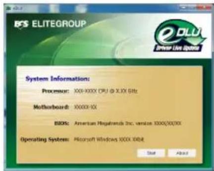
text_image
BFS ELITEGROUP System Information: Processus: XXX-XXXX CPU @ X.XX GHz Motherboard: XXXXX-10 BDOs: American Regalmnds Inc. version: XXXX/300/XX Operating System: Microsoft Windows 300X DDB Start AbouteBLU
ECS eBLU utility makes BIOS update faster and easier. eBLU will list the latest BIOS with a default check-mark. Click "install" button to install.

text_image
ELITEGROUP System Information Processor: XXX-XXXX CPU - 8.5.5x GHz Masterboard: XXXXX-XX BIOS: American Megabyte Inc. version 3000/2007/xx Operating System: Microsoft Windows 3000X 3000X Recommended Updates Order Current Version Online Version Special Updates Check Updates Install About
Microsoft .NET Framework 3.5 is required.
Chapter 5
Trouble Shooting
Start up problems during assembly
After assembling the PC for the first time you may experience some start up problems. Before calling for technical support or returning for warranty, this chapter may help to address some of the common questions using some basic troubleshooting tips. You may also log onto our ECS website for more information: http://www.ecs.com.tw/ECSWebSite/Support/Support_FAQ.aspx?MenuID=49&childid=M_49&LanID=0
a) System does not power up and the fans are not running.
- Disassemble the PC to remove the VGA adaptor card, DDR memory, LAN, USB and other peripherals including keyboard and mouse. Leave only the motherboard, CPU with CPU cooler and power supply connected. Make sure the power cord is plugged into the wall socket & the switch on the Power Supply Unit (PSU) is turned "on" as well. Turn on again to see if the CPU and power supply fans are running.
- Make sure to remove any unused screws or other metal objects such as screwdrivers from the inside PC case. This is to prevent damage from short circuit.
- Check the CPU FAN connector is connected to the motherboard.
- For Intel platforms check the pins on the CPU socket for damage or bent. A bent pin may cause failure to boot and sometimes permanent damage from short circuit.
b) Power is on, fans are running but there is no display
- Make sure the monitor is turned on and the monitor cable is properly connected to the PC.
- Check the VGA adapter card (if applicable) is inserted properly.
- Listen for beep sounds. If you are using internal PC speaker make sure it is connected.
a. continuous 3 short beeps: memory not detected
b. 1 long beep and 8 short beeps: VGA not detected
c) The PC suddenly shuts down while booting up.
- The CPU may experience overheating so it will shutdown to protect itself. Apply the thermal grease onto the CPU heatsink & ensure the CPU fan is well-connected with the CPU heatsink. Check if the CPU fan is working properly while the system is running.
- From the BIOS setting, try to disable the Smartfan function to let the fan run at default speed. Doing a Load Optimised Default will also disable the Smartfan.
Start up problems after prolong use
After a prolong period of use your PC may experience start up problems again. This may be caused by breakdown of devices connected to the motherboard such as HDD, CPU fan, etc. The following tips may help to revive the PC or identify the cause of failure.
- Clear the CMOS values using the CLR_CMOS jumper. Refer to CLR_CMOS jumper in Chapter 2 for Checking Jumper Settings in this user manual. When completed, follow up with a Load Optimised Default in the BIOS setup.
- Check the CPU cooler fan for dust. Long term accumulation of dust will reduce its effectiveness to cool the processor. Clean the cooler or replace a new one if necessary.
- Remove the hard drive, optical drive or DDR memory to determine which of these components may be at fault.
- Check whether there is any bulked up electrolytic capacitor or abnormal component.
Please logo onto our ECS website: http://www.ecs.com.tw/ECSWebSite/Support/Technical_Support_List.aspx?MenuID=50&LanID=0 for more information.
Maintenance and care tips
Your computer, like any electrical appliance, requires proper care and maintenance. Here are some basic PC care tips to help prolong the life of the motherboard and keep it running as best as it can.
- Keep your computer in a well ventilated area. Leave some space between the PC and the wall for sufficient airflow.
- Keep your computer in a cool dry place. Avoid dusty areas, direct sunlight and areas of high moisture content.
- Routinely clean the CPU cooler fan to remove dust and hair.
- In places of hot and humid weather you should turn on your computer once every other week to circulate the air and prevent damage from humidity.
- Add more memory to your computer if possible. This not only speeds up the system but also reduces the loading of your hard drive to prolong its life span.
- If possible, ensure the power cord has an earth ground pin directly from the wall outlet. This will reduce voltage fluctuation that may damage sensitive devices.
Basic Troubleshooting Flowchart

flowchart
graph TD
    A["ug@rewoP"] --> B{Unit}
    B -->|Yes| C{Check if monitor has display}
    C -->|No| D{dn#os peeB v:}
    D -->|Yes| E[":speeb trohs 3lf-DIMM memory not properly inserted or memory failure"]
    D -->|No| F[":speeb trohs 8 dna peeb gnol fi"]
    E --> G[":seeb trohs 3lf-DIMM memory not properly inserted or memory failure"]
    F --> H[":seeb trohs 8 dna peeb gnol fi"]
    G --> I["CLR CMOS and restart. AMR@catnoc ,ll&f"]
    H --> J[":seeb trohs 8 dna peeb gnol fi"]
    I --> K["d: eust received larehpireP"]
    K --> L["elborp DD rpre ntes NO MCRD not een"]
    L --> M["Yes"]
    M --> N["Yes"]
    N --> O["Yes"]
    O --> P["kce: dna SOMC RLC rew ep V21 UPC detcennec si"]
    P --> Q["CP eht catseR"]
    Q --> R{no micr: yalpsid sah}
    R -->|No| S["elborp draoB AMR@catnoc >-"]
    S --> T["hc#ws USP no nruT texcos llaw otcennoc r .tratser dna"]
    T --> U["tratser dna"]
    U --> V["M C SSC"]
    V --> W["ts ot liatsyS estgIB ydore"]
    W --> X["alt"]
    X --> Y["Yes"]
    Y --> Z["Yes"]
    Z --> AA["kce: dna SOMC RLC rew ep V21 UPC detcennec si"]
    AA --> AB["CP eht catseR"]
    AB --> AC{kce: dna SOMC RLC rew ep V21 UPC detcennec si}
    AC --> AD["Yes"]
    AD --> AE["yes"]
    AE --> AF["Yes"]
    AF --> AG["kce: dna SOMC RLC rew ep V21 UPC detcennec si"]
    AG --> AH["Yes"]
    AH --> AI["kce: dna SOMC RLC rew ep V21 UPC detcennec si"]
    AI --> AJ["Yes"]
    AJ --> AK["kce: dna SOMC RLC rew ep V21 UPC detcennec si"]
    AK --> AL["Yes"]
    AL --> AM["kce: dna SOMC RLC rew ep V21 UPC detcennec si"]
    AM --> AN["Yes"]
    AN --> AO["kce: dna SOMC RLC rew ep V21 UPC detcennec si"]
    AO --> AP["Yes"]
    AP --> AQ["kce: dna SOMC RLC rew ep V21 UPC detcennec si"]
    AQ --> AR["Yes"]
    AR --> AS["kce: dna SOMC RLC rew ep V21 UPC detcennec si"]
    AS --> AT["Yes"]
    AT --> AU["kce: dna SOMC RLC rew ep V21 UPC detcennec si"]
    AU --> AV["Yes"]
    AV --> AW["kce: dna SOMC RLC rew ep V21 UPC detcennec si"]
    AW --> AX["Yes"]
    AX --> AY["kce: dna SOMC RLC rew ep V21 UPC detcennec si"]
    AY --> AZ["Yes"]
    AZ --> BA["kce: dna SOMC RLC rew ep V21 UPC detcennec si"]
    BA --> BB["Yes"]
    BB --> BC["kce: dna SOMC RLC rew ep V21 UPC detcennec si"]
    BC --> BD["Yes"]
    BD --> BE["kce: dna SOMC RLC rew ep V21 UPC detcennec si"]
    BE --> BF["Yes"]
    BF --> BG["kce: dna SOMC RLC rew ep V21 UPC detcennec si"]
    BG --> BH["Yes"]
    BH --> BI["kce: dna SOMC RLC rew ep V21 UPC detcennec si"]
    BI --> BJ["Yes"]
    BJ --> BK["kce: dna SOMC RLC rew ep V21 UPC detcennec si"]
    BK --> BL["Yes"]
    BL --> BM["kce: dna SOMC RLC rew ep V21 UPC detcennec si"]
    BM --> BN["Yes"]
    BN --> BO["kce: dna SOMC RLC rew ep V21 UPC detcennec si"]
    BO --> BP["Yes"]
    BP --> BQ["kce: dna SOMC RLC rew ep V21 UPC detcennec si"]
    BQ --> BR["Yes"]
    BR --> BS["kce: dna SOMC RLC rew ep V21 UPC detcennec si"]
    BS --> BT["Yes"]
    BT --> BU["kce: dna SOMC RLC rew ep V21 UPC detcennec si"]
    BU --> BV["Yes"]
    BV --> BW["kce: dna SOMC RLC rew ep V21 UPC detcennec si"]
    BW --> BX["Yes"]
    BX --> BY["kce: dna SOMC RLC rew ep V21 UPC detcennec si"]
    BY --> BZ["Yes"]
    BZ --> CA["kce: dna SOMC RLC rew ep V21 UPC detcennec si"]
    CA --> CB["Yes"]
    CB --> CC["kce: dna SOMC RLC rew ep V21 UPC detcennec si"]
    CC --> CD["Yes"]
    CD --> CE["kce: dna SOMC RLC rew ep V21 UPC detcennec si"]
    CE --> CF["Yes"]
    CF --> CG["kce: dna SOMC RLC rew ep V21 UPC detcennec si"]
    CG --> CH["Yes"]
    CH --> CI["kce: dna SOMC RLC rew ep V21 UPC detcennec si"]
    CI --> CJ["Yes"]
    CJ --> CK["kce: dna SOMC RLC rew ep V21 UPC detcennec si"]
    CK --> CL["Yes"]
    CL --> CD
Memo
Chapter 5