T181-Z70 - Server GIGABYTE - Free user manual and instructions
Find the device manual for free T181-Z70 GIGABYTE in PDF.

User questions about T181-Z70 GIGABYTE
0 question about this device. Answer the ones you know or ask your own.
Ask a new question about this device
Download the instructions for your Server in PDF format for free! Find your manual T181-Z70 - GIGABYTE and take your electronic device back in hand. On this page are published all the documents necessary for the use of your device. T181-Z70 by GIGABYTE.
USER MANUAL T181-Z70 GIGABYTE
© 2021 GIGA-BYTE TECHNOLOGY CO., LTD. All rights reserved.
The trademarks mentioned in this manual are legally registered to their respective owners.
Disclaimer
Information in this manual is protected by copyright laws and is the property of GIGABYTE.
Changes to the specifications and features in this manual may be made by GIGABYTE without prior notice. No part of this manual may be reproduced, copied, translated, transmitted, or published in any form or by any means without GIGABYTE's prior written permission.
Documentation Classifications
In order to assist in the use of this product, GIGABYTE provides the following types of documentation:
■ User Manual: detailed information & steps about the installation, configuration and use this product (motherboard), covering hardware, BIOS and BMC firmware.
■ Service Guide: detailed information & steps about the installation, configuration and use of this product (server barebones), covering hardware & BIOS
■ Quick Installation Guide: a short guide with visual diagrams that you can reference easily for installation purposes
Please see the support section of the online product page to check the current availability of these documents
For More Information
For related product specifications, the latest firmware and software, and related information, please visit our website at:
http://www.gigabyte.com
For GIGABYTE distributors and resellers, additional sales & marketing materials are available from our reseller portal:
http://reseller.b2b.gigabyte.com
For further information & technical assistance, please contact your GIGABYTE sales representative.
You may also message GIGABYTE server directly by email, Facebook or twitter
Email: server.grp@gigabyte.com
Facebook: https://www.facebook.com/gigabyteserver
Twitter: https://twitter.com/GIGABYTEServer
Table of Contents
Chapter 1 Getting Started....5
1-1 Software Requirement .... 5
1-2 Gigabyte Management Console Network Configuration 6
1-3 Log In Gigabyte Management Console....7
1-3-1 Required Browser Settings:....9
1-4 Quick Button and Logged-in User 10
1-5 Help.... 11
1-6 Menu Bar.... 11
Chapter 2 Enter Gigabyte Management Console....13
2-1 Dashboard.... 13
2-2 Sensor....14
2-2-1 Sensor Detail....15
2-3 System Inventory 17
2-3-1 CPU Inventory 17
2-3-2 DIMM Inventory 18
2-3-3 PCI Inventory....18
2-3-4 HDD Inventory....19
2-3-5 NIC Inventory....19
2-3-6 GPU Inventory....20
2-4 FRU Information....22
2-5 Logs & Reports 24
2-5-1 IPMI Event Log 24
2-5-2 System Log....26
2-5-3 Audit Log 27
2-5-4 Video Log 28
2-6 Settings 29
2-6-1 Captured BSOD 29
2-6-2 Date & Time....30
2-6-3 External User Services....31
2-6-4 KVM Mouse Settings....42
2-6-5 Log Settings....44
2-6-6 Media Redirection Settings....47
2-6-7 Network Settings ....54
2-6-8 NVMe MI Management....61
2-6-9 PAM Order Settings....63
2-6-10 Platform Event Filter....64
2-6-11 Services....73
2-6-12 SMTP Settings....77
2-6-13 SSL Settings....80
2-6-14 System Firewall 85
2-6-15 User Management....95
2-6-16 Video Recording....100
2-6-17 Fan Policy....109
2-6-18 Power Consumption 111
2-7 Remote Control....103
2-8 Images Redirection....109
2-8-1 Remote Media 110
2-9 Power Control 111
2-10 Maintenance Group.... 112
2-10-1 Backup Configuration 113
2-10-2 Firmware Image Location....115
2-10-3 Firmware Update....116
2-10-4 HPM Firmware Update....122
2-10-5 Firmware Information....125
2-10-6 Preserve Configuration....126
2-10-7 Restore Configuration....131
2-10-8 Restore Factory Defaults....132
2-10-9 System Administrator....133
2-10-10 Sign Out....134
Chapter 1 Getting Started
1-1 Software Requirement
- Client machine with 8GB RAM.
- If the client machine has 4GB RAM, there will be lag in Video/keyboard/mouse functionality.
•
Supported Browsers
- Chrome latest version.
- IE 11 and above.
- Firefox (with limited support).

Note: It is advisable to use Chrome or IE for H5Viewer, since Firefox has its own memory limitations
1-2 Gigabyte Management Console Network Configuration
Follow the instruction to enable the console redirection function.
- You can gather the IP address on the POST screen.
text_image
GIGABYTE™ BME IP : 10.1.6.113 Press- Or, Go to BIOS setup menu.
- Select Server Management.
- Select BMC network Configuration.
- Define Configuration Address source to DynamicBmcDhcp or Static.
- Save and Exit.
- The BMC IP Address will appear on the IPv4 Address parameter.
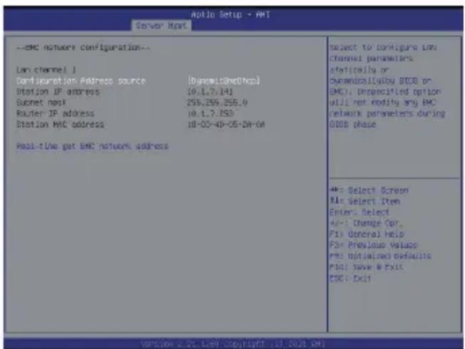
text_image
Aptio Setup - AHT Server Hprt --EMC network configuration-- Lam channel | Configuration Address source (DyseM13@edhop) Station JP address 10.1.7.141 Subnet mask 256,255,255.0 Router JP address 10.1.7.253 Station BMC address 10-00-40-05-04-04 Pool-time got BMC network address select to configure LAM Channel parameters: statically or channelally by BDCB or BMC; unspecified option will not modify any BMC network parameters during BDCB phase += Select Screen += Select Item Enter: Select +/-: Change Opt. Fix: General Help For: Previous Values For: Optimal defaults File: Save & Exit EPC: Exit version 2.21.1.09 Copyright 10.2028 (AM)- Save the configuration and exit BIOS setup menu.
1-3 Log In Gigabyte Management Console
To access the Gigabyte Management Console, the BMC Web utility will prompt you to enter the User Name and Password.

text_image
Username Password Remember Username Sign me inI forgot my password
The fields are explained as follows:
For basic login to the BMC Web UI, use the following login:
- Username: admin
- Password: Refer to unique MB serial number.

NOTE!
If your motherboard / server version is older than G9 (upgrade version), then use the following login:
Username:admin
Password: password
This serial number can be found on the serial number sticker located on the motherboard of every GIGABYTE server motherboard and system. The unique pre-programmed password will be the last 11 characters of the serial number. For example, for the below serial number, the password will be "JG4P6400027

text_image
1/A/JG4P64 00027GIGABYTE will also affix new stickers that display the unique BMC password (example below) to both the product box (packaging) and to the CPU cover (for motherboards sold separately) or the server chassis.

text_image
Unique BMC Password JG4P6400027Please see the reference guide below / attached for where to find locations of this sticker according to product / model type.
Products that have been implemented with this change will be indicated as version G9 on the "Upgrade Version" sticker located on the motherboard / motherboard anti-static packaging / server chassis / server packaging

text_image
UPG VER: G□1 G□2 G□3 G□4 G□5 G□6 G□7 G□8 G□9 G□10Remember Username: Check this option to remember your login credentials.
Sign me in: After entering the required credentials, click the Sign me in to login to GUI.
I forgot my password: If you forget your password, you can generate a new one using this link.
Enter the username, click on Forgot Password link. This will send the newly generated password to the configured Email-ID for the user.
1-3-1 Required Browser Settings:
Allow file download from this site: For Internet Explorer, Choose Tools ->Internet Options ->Security Tab, based on device setup, select among Internet, Local intranet, trusted sites and restricted sites. Click Custom level.... In the Security Settings - Zone dialog opened, under settings, find Downloads option, Enable File download option. Click OK to the entire dialog boxes.
For all Other Browsers, accept file download when prompted.
Enable javascript for this site: The icon indicates whether the javascript setting is enabled in browser.
Enable cookies for this site: The icon indicates whether the cookies setting are enabled in browser.

Cookies must be enabled in order to access the website.
1-4 Quick Button and Logged-in User
The user information and quick buttons are located at the top right of the Web GUI. A screenshot of the logged-in user information is shown below.


User Information
The logged-in user information shows the logged-in user, his/her privilege and the four quick buttons allowing you to perform the following functions:
Logged-in user and its privilege level
This option shows the logged-in user name and privilege. There are five kinds of privileges.
User: Only valid commands are allowed.
Operator: All BMC commands are allowed except for the configuration commands that can change the behavior of the out-of-hand interfaces.
Administrator: All BMC commands are allowed.
No Access: Login access denied.
OEM: All OEM commands are allowed.
Notification: Click the icon to view the notification messages.
Refresh: Click the icon to reload the current page.
Sync: Click the icon to synchronize with Latest Sensor and Event Log updates.
Sign-out: Click the icon to log out of the Web GUI.
Warning: Click to view the warning messages.
1-5 Help
Help - The Help icon (?) is Located at the top right of the each page in Web GUI. Click this help icon to view more detailed field descriptions.
1-6 Menu Bar
The menu bar displays the following:
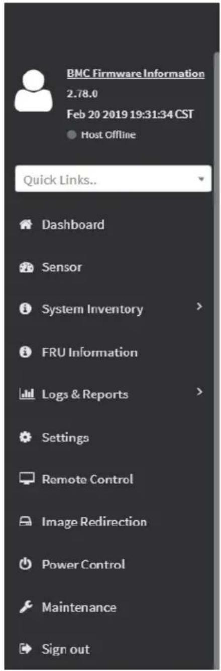
text_image
BMC Firmware Information 2.78.0 Feb 20 2019 19:31:34 CST Host Offline Quick Links.. Dashboard Sensor System Inventory > FRU Information Logs & Reports > Settings Remote Control Image Redirection Power Control Maintenance Sign outThis page intentionally left blank
Chapter 2 Enter Gigabyte Management Console
2-1 Dashboard
The Dashboard page gives the overall information about the status of a device.
To open the Dashboard page, click Dashboard from the menu bar. It displays the following:

text_image
BMC Emmore Information 1.78.0 Feb 28 2009 13:31:34 CSE Current Office Quick Units... Dashboard Sensor System Inventory FBU Information Logs & Reports Settings Remote Control Image Redirection Power Control Maintenance Sign out 2008-01-05 09:24:10 (UTC+00:00 UTC) Dashboard Control Panel 16 d 9 hrs BMC Up Time 656 Pending Descriptions More info 15 Access Logs More info Today (a) Details No events for today... 30 days (≈) Details syatem_event 31 events Sync Refresh admin Home - Dashboard Sensor Monitoring All sensors are good now! Currently recoveredDashboard
A brief description of the Dashboard page is given below.
BMC Up Time
It indicates the Power On time.
Pending Deassertions
It lists the all pending events incurred by various sensors and occupied/available space in logs can be viewed. To know about the pending events details, click the More info link. This navigates to the Event Log page.
Access Logs
A graphical representation of all events incurred by various sensors and occupied/available space in logs can be viewed, if you click on the More info link, you can view the Audit Log page.
Today & 30 Days (Event Logs)
This page displays the list of event logs occurred by the different sensors on this device. Click Details link on Today and 30 days to view the event logs for Today and 30 days respectively.
Sensor Monitoring
It lists all the critical sensors on the device. If you click on any list sensor, you can view the Sensor detail page with the Sensor information and Sensor Events details.
2-2 Sensor
The Sensor Readings page displays all the sensor related information.
To open the Sensor Readings page, click Sensor from the menu. Click on any sensor to show more information about that particular sensor, including thresholds and a graphical representation of all associated events.
A sample screenshot of Sensor Readings page is shown below.

text_image
MEGARAC SP-X European Information 3.45.89014 Over 9/2016 30027501 RST © Next-Offing Quick Links... Dashboard Sensor System Inventory RBU Information Logs & Reports Settings Remote Control Image Redirection Power Control Maintenance Sensor Reading Live reading of all sensors Critical Sensors (2) ROC1 Temp ROC2 Temp Discrete Sensor States (2) Sensor Name State SEL_sensor No state defined Watchdog No state defined Normal Sensors (1) Sensor Name Reading Behavior BBU2 Temp 20 °C Disabled Sensors (15) Temp_1 Temp_3 Chassis_Intr Voltage_1CC Par_1 Par_2 Temp_3 Temp_4 voltage_2.5V voltage_5V voltage1_2V Temp_3 Expander Temp BBU1 Temp Expander2 TempThe Sensor Readings page contains the following information:
In this Sensor Reading page, Live readings for all the available sensors with details like Sensor Name, Status, Current Reading and Behavior will be appeared, else you can choose the sensor type that you want to display from the list. Some examples for sensors are Temperature Sensors, Fan Sensors, Watchdog Sensors and Voltage Sensors etc.
Note: Four DIMM Temp sensors are deployed for monitoring the DIMM temperature on the system. Users must take notice that the live reading of each DIMM Temp sensor indicates the temperature of a DIMM group, not the temperature of a specific DIMM.

Note: Four DIMM Temp sensors are deployed for monitoring the DIMM temperature on the system. Users must take notice that the live reading of each DIMM Temp sensor indicates the temperature of a DIMM group, not the temperature of a specific DIMM.
2-2-1 Sensor Detail
Select a particular Sensor from the Critical Sensor or Normal Sensor lists. The Sensor Information as Live Widget and Thresholds for the selected sensor will be displayed as shown below.

line
| Time (HH:03M:55) | Temperature (°C) | | ---------------- | ---------------- | | 12:30:44 | 30 | | 12:30:53 | 30 |
Note: For Illustrative Purpose, a sample screenshot of Sensor detail page with Change holds option is shown and explained below.

text_image
MEGARAC SP-X Browse Information 1.00.00014 Apr 13 2017 08:30:00 EST © Next Office Quick times... Dashboard Sensor System Inventory FRU Information Log & Reports Settings Remote Control Image Direction Sensor Thresholds Change Threshold Values Sensor Name Temp_1 Upper Non-recoverable 30 Upper Critical 30 Upper Non-critical 30 Lower Non-critical 10 Sync Refresh admin Name Settings Sensor Thresholds
Note: Widgets are little gadgets, which provide real time information about a particular sensor. User can track a sensor's behavior over a specific amount of time at specific intervals. The result will be displayed as a line graph in the widget. The session will not expire, until the widgets gets a live data of the last widget that is kept opened.
For the selected sensor, this widget gives a dynamic representation of the readings for
the sensor.
There are six types of thresholds:
• Lower Non-Recoverable (LNR)
- Lower Critical (LC)
• Lower Non-Critical (LNC)
• Upper Non-Recoverable (UNR)
• Upper Critical (UC)
• Upper Non-Critical (UNC)
The threshold states could be Lower Non-critical - going low, Lower Non-critical - going high, Lower Critical - going low, Lower Critical - going high, Lower Non-recoverable - going low, Lower Non-recoverable - going high, Upper Non-critical - going low, Upper Non-critical - going high, Upper Critical - going low, Upper Critical - going high, Upper Non-recoverable - going low, Upper Non-recoverable - going high.
A graphical view of these events (Number of Entries vs. Thresholds) can be viewed as shown in the Sensor Readings page screenshot.
2-3 System Inventory
The System Inventory page displays the following information:
- CPU Inventory
- DIMM Inventory
- PCI Inventory
- HDD Inventory
- NIC Inventory
• GPU Inventory (Nvidia A100 only)
A screenshot displaying the menu items under System Inventory is shown below.
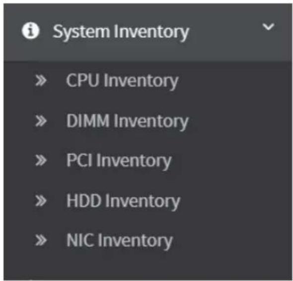
text_image
System Inventory » CPU Inventory » DIMM Inventory » PCI Inventory » HDD Inventory » NIC InventoryA detailed description of System Inventory is given below.
2-3-1 CPU Inventory
This page displays all detected CPUs on this device. Select one CPU to see the details of that entry or click on Expand All to view all entries in details. Click Download SMBIOS file to download the SMBIOS file.

text_image
CPU inventory File Storage Accessories Settings Parameters System Cybersecurity CPU Information Data & Reports Settings Capacity Information for CPU CPU Command/Storage Capacity Capacity Capacity Capacity Capacity Capacity Capacity Capacity Capacity Capacity Capacity Capacity Capacity Capacity Capacity Capacity Capacity Capacity Capacity Capacity Capacity Capacity Capacity Capacity Capacity Capacity Capacity Capacity Capacity Capacity Capacity Capacity Capacity Capacity Capacity Capacity Capacity Capacity Capacity Capacity Capacity Capacity Capacity Capacity Capacity Capacity Capacity Capacity Capacity Capacity capacity2-3-2 DIMM Inventory
This page displays all detected DIMMs on this device. It allows you to see memory attributes, individual memory details or all entries in detail by clicking on Expand All. Click Download SMBIOS file to download the SMBIOS file.

This page displays all detected PCI cards on this device. It allows you to see on-board PCI cards, add-on PCI cards or all entries in detail by clicking on Expand All. Click Download SMBIOS file to download the SMBIOS file.
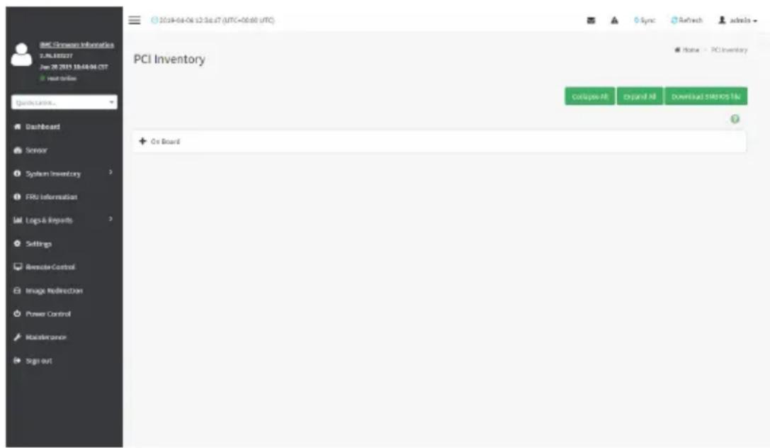
text_image
PCI Inventory Collapse All Expand All download https://tfu + On Board2-3-4 HDD Inventory
This page displays all detected HDDs on this device. It allows you to see on-board HDDs, add-on HDDs or all entries in detail by clicking on Expand All. Click Download SMBIOS file to download the SMBIOS file.
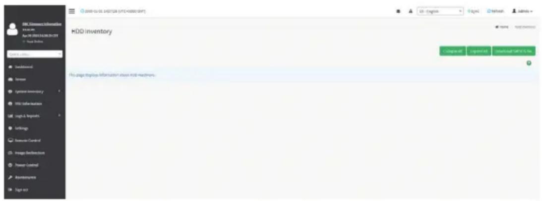
text_image
HDD inventory File page displays information about mini installments.2-3-5 NIC Inventory
This page displays all detected NICs on this device. It allows you to on-board NICs, add-on NICs or all entries in detail by clicking on Expand All. Click Download SMBIOS file to download the SMBIOS file.
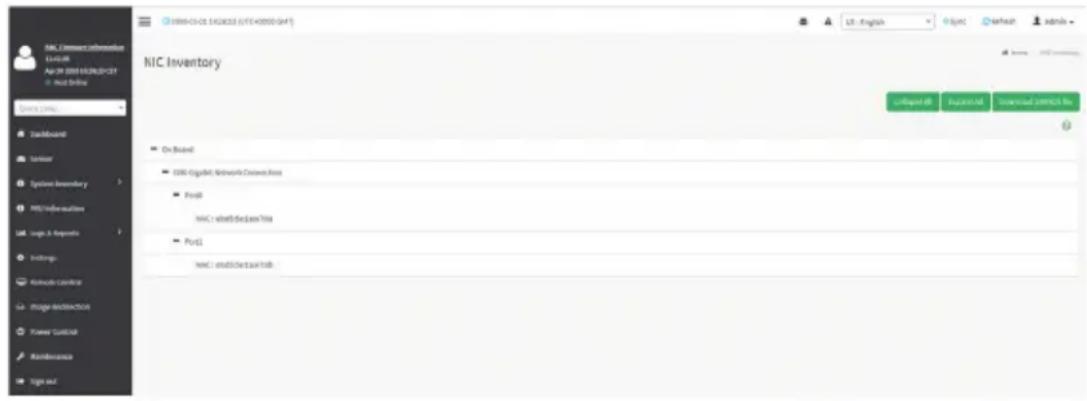
text_image
NIC Inventory On Board ODR: Digital Network Control Price Port NIC: on board dates this Port1 NIC: on board date this2-3-6 GPU Inventory
This page displays all detected GPU card on this device. It allows you to view GPU card all entries in detail by clicking on Expand All.
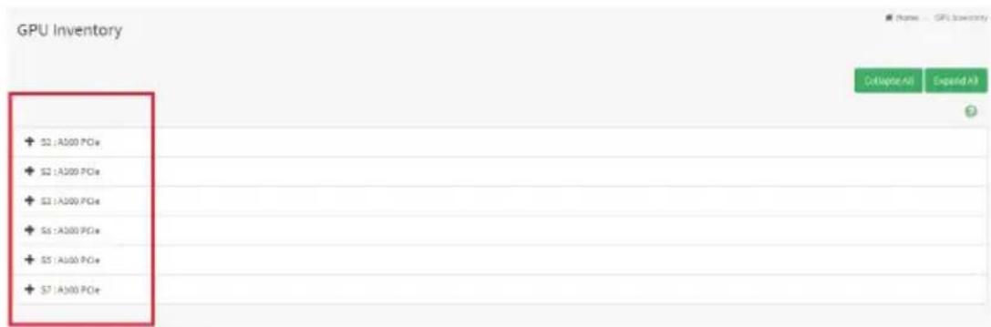
text_image
GPU Inventory + S2 : A300 PCIe + S2 : A200 PCIe + S3 : A200 PCIe + S3 : A300 PCIe + S5 : A300 PCIe + S7 : A300 PCIe C:\Apache\All Expand\All
text_image
S1 : A100 PCIe + Detail Information for GPU + Temperature Information for GPU + Status Information for GPU + Power Information for GPU + Clock Information for GPUDetail information for GPU
- GPU Information
- Capabilities
- NVLink Information
Temperature Information for GPU
- GPU Temperature
• Extended Precision GPU Temperature
Status Information for GPU
• Accumulated Utilization
• Power Supply
Power Information for GPU
• Power Consumption
Clock Information for GPU
• Graphics Clock Frequency
• -Memory Clock Frequency
2-4 FRU Information
FRU Information page displays the BMC's FRU device information. FRU page shows information like Basic Information, Chassis Information, Board Information and Product Information of the FRU device.
To open the FRU Information page, click FRU Information from the menu bar. Select a FRU Device ID from the FRU Information section to view the details of the selected device. A screenshot of FRU Information page is shown below.
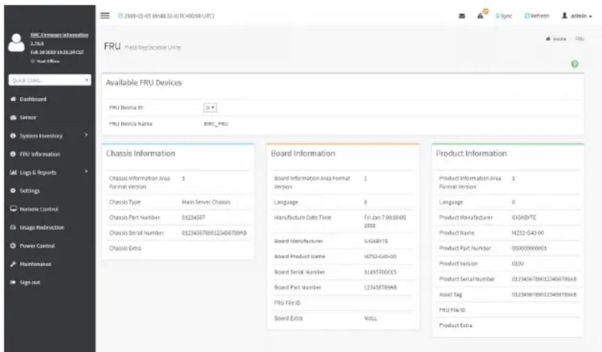
text_image
BMC Ermore Information 1.710 Feb 28 2009 13:31:34 GMT Host Office FRU Field Replaceable Units Available FRU Devices FRU Device ID: D FRU Device Name: BMC_FRU Chassis Information Chassis Information Area 1 Format Version Chassis Type Main Server Chassis Chassis Part Number 01234567 Chassis Serial Number 0123456786123456789AB Chassis Extra Board Information Board Information Area Format Version: Language: Fri_Jan 7:00:00:00 2000 Board Manufacturer: GIGABYTE Board Product Name: MZS2-G40-00 Board Serial Number: SJ695700015 Board Part Number: L23456789AB FRU File ID: Board Extra NULL Product Information Product Information Area Format Version: Language: Product Manufacturer: GIGABYTE Product Name: MZS2-G40-00 Product Part Number: 00000000001 Product Version: 0100 Product Serial Number: 01234567890123456789AB Asset Tag: 01234567890123456789AB FRU File ID: Product ExtraThe following fields are displayed here for the selected device:
Available FRU Devices
• FRU device ID - Select the device ID from the drop down list
- FRU Device Name - The device name of the selected FRU device.
Chassis Information
• Chassis Information Area Format Version
- Chassis Type
- Chassis Part Number
- Chassis Serial Number
- Chassis Extra
Board Information
• Board Information Area Format Version
- Language
• Manufacture Date Time
- Board Manufacturer
- Board Product Name
- Board Serial Number
- Board Part Number
- FRU File ID
- Board Extra
Product Information
• Board Information Area Format Version
- Language
• Manufacture Date Time
- Board Manufacturer
- Board Product Name
- Board Serial Number
- Board Part Number
- FRU File ID
- Board Extra
2-5 Logs & Reports
The Logs & Reports page displays the following information:
- IPMI Event Log
- System Log
- Audit Log
- Video Log
A screenshot displaying the menu items under Logs & Reports is shown below.
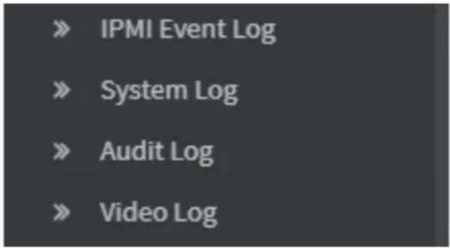
text_image
» IPMI Event Log » System Log » Audit Log » Video LogA detailed description of Logs & Reports is given below.
2-5-1 IPMI Event Log
This page displays the list of event logs occurred by the different sensors on this device. Double click on a record to see the details of that entry. You can use the sensor type or sensor name filter options to view those specific events or you can also sort the list of entries by clicking on any of the column headers.
To open the Event Log page, click Logs & Reports > IPMI Event Log from the menu bar. A sample screenshot of Event Log page is shown below.
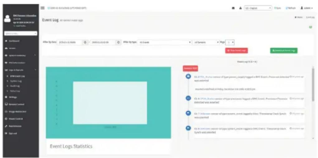
text_image
BCT Event Log Event Log: All Generated Events Log Offer by Date: BCT.01.01 00:00 2008.01.01 01:50 Offer by Type: All Events All Samples Right Data Event Log Downloaded Event Log EventLog (BTS - A) Identity Size ID: BCT_01_01_01_01_01_01_01_01_01_01_01_01_01_01_01_01_01_01_01_01_01_01_01_01_01_01_01_01_01_01_01_01_01_01 Assumed undefined per index, two window size, each type. ID: BCT.01_01_01_01_01_01_01_01_01_01_01_01_01_01_01_01_01_01_01_01_01_01_01_01_01_01_01_01_01_01_01_01_01_3 ID: BCT.02_01_01_01_01_01_01_01_01_01_01_01_01_01_01_01_01_01_01_01_01_01_3 ID: BCT.02_02_02_02_02_02_02_02_02_02_02_02_02_02_02_02_3 ID: BCT.02.02.02.02.02.02.02.02.02.02.02.02.3 ID: BCT.02.34.34.34.34.34.34.34.34.34.34.34.34.34.34.34.34.34.34.34.34.34.34.34.34.34.34.34.34.34.34.34.34.34.34 ID: BCT.34.34.34.34.34.34.34.34.34.34.34.34.34.34.34.34.34.34.34.34.34.34.34.34.34.34.34.34.34.34.34.34 ID: ID: bctdsmn: pssor-6type (system_main) : gga a (BMT_end), Tmocamp clock, Synch unit asserted Event Logs StatisticsThe Event Log page consists of the following fields:
Filter By Date: Filtering can be done by selecting Start Date and End Date.

Note: Date should be in MM/DD/YYYY format. default, all log time will be displayed in BMC time zone.
Filter By Type: The category could be either All Events, System Event Records, OEM Event Records, BIOS Generated Events, SMI Handler Events, System Management Software Events, System Software - OEM Events, Remote Console software Events, Terminal Mode Remote Console software Events.

Note: Once the Filter By Date and Filter type are selected, the list of events will be displayed with the Event ID, Time Stamp, Sensor Type, Sensor Name and Description.
Event Log Statistics: Displays the statistical graph for the selected date.
Clear Event Logs: To delete all the event logs.
Download Event Logs: To download the event logs.
Procedure
- From the Filter By Date field, select the time period by Start Date and End Date using Calendar for the event categories.
- From the Filter By Type field, select the Type of the event and Sensor name to view the events for the date. The events will be displayed based on the selected time period.
- To clear all events from the list, click Clear All Event Logs.
- To download the event logs, click Download Event Logs.
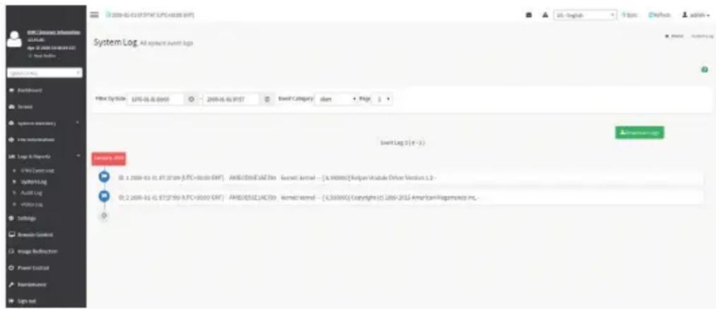
2-5-2 System Log
To open the System Log page, click Logs & Reports > System Log from the menu bar. A sample screenshot of System Log page is shown below.
A sample screenshot of Video Log page is shown below.
text_image
BBL Resource Information Default Age 37:00:08:08:08Real Data
System Log All system event logs Fiber System: JYR-06 & 0955 2009-05-01 9157 Email Category: start Page 1 E-mail Log 2 (n=1) Category: None 01: 1 2009-01-01, 01:37:09 (L.P.C.=00:00 GBF) AMBD/EtisD1AE Dvo Guesetl Annel - [A.99000] Relpur Module Driver Version 1.2 - 02: 2 2009-01-01, 01:37:09 (L.P.C.=00:00 GBF) AMBD/EtisD1AE Dvo Kornetic Annel - [C.50000] Copyright (2) 2009-2012 American Technologies Inc.To view System Log, click the System Log tab to view all system events. Entries can be filtered based on Filter By Date (Start Date and End Date) and Event Category like Alert, Critical, Error, Notification, Warning, Debug, Emergency and Information.
Download Event Logs: To download the event logs.
2-5-3 Audit Log
Audit Log page will display all the system events occurred in this device that has been already configured.

Note: Logs have to be configured under Settings -> Log Settings > Advanced Log Settings in order to display any entries.
To open the Event Log page, click Logs & Reports > Audit Log from the menu bar.
A sample screenshot of Audit Log page is shown below.
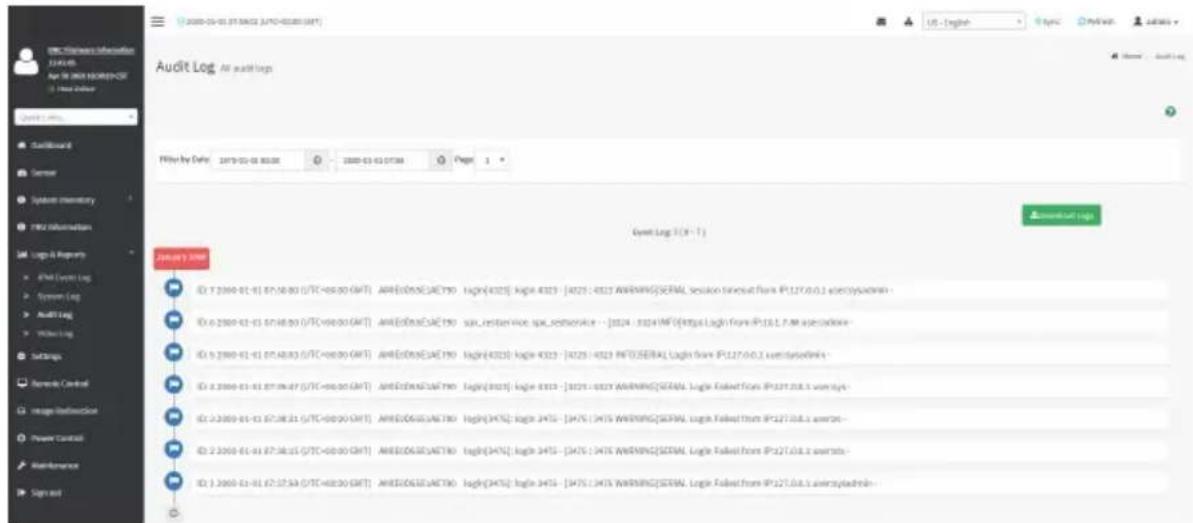
text_image
Audit Log: All audit logs Filter by Date 2019-03-03 05:00 2009-03-03 07:00 Page 1 Event Log 3 (X - Y) ID: 7.2009-01-01 07:58:00 (UTC+08:00 GMT) ARIEDISELACTNO login(4Q25) login 4Q25 - [4Q25 : 4Q25 WARNING] SERIAL Session times out from IP:127.0.0.1 eventsysdrom - ID: 6.2009-01-01 07:48:00 (UTC+08:00 GMT) ARIEDISELACTNO spx_reservice spx_reservice - [3Q24 : 3Q24 INF] https://login.farm IP:13.1.7.m specidone- ID: 6.2009-01-01 07:48:03 (UTC+08:00 GMT) ARIEDISELACTNO login(4Q25) login 4Q25 - [4Q25 : 4Q25 INFO] SERIAL Login from IP:127.0.0.2 eventsysdrom - ID: 6.2009-01-01 07:48:47 (UTC+08:00 GMT) ARIEDISELACTNO login(4Q25) login 4Q25 - [4Q25 : 4Q25 WARNING] SERIAL Login Faked From IP:127.0.8.1 eventsysdrom - ID: 6.2009-01-01 07:38:31 (UTC+08:00 GMT) ARIEDISELACTNO login(3475) login 3475 - [3475 : 3475 WARNING] SERIAL Login Faked from IP:127.0.8.1 eventsysdrom - ID: 6.2009-01-01 07:38:35 (UTC+08:00 GMT) ARIEDISELACTNO login(3475) login 3475 - [3475 : 3475 WARNING] SERIAL Login Faked from IP:127.0.8.1 eventsysdrom - ID: 6.2009-01-01 07:37:53 (UTC+08:00 GMT) ARIEDISELACTNO login(3475) login 3475 - [3475 : 3475 WARNING] SERIAL Login Faked from IP:127.0.8.1 eventsysdrom -To view Audit Log, click the Audit Log tab to view all audit events for this device.
Download Event Logs: To download the event logs.
2-5-4 Video Log
To open the Video Log page, click Logs & Reports > Video Log from the menu bar. A sample screenshot of Video Log page is shown below.
Note: Video Trigger Settings should be enabled, to display the Video Log page. Video Trigger Settings can be configured under Settings -> Video Recording -> Auto Video Settings -> Video Trigger Settings.
A sample screenshot of Video Log page is shown below.

text_image
MEGARAC SP-X Sensor System Inventory FRU Information Logs & Reports IPMS Event Log Systems Log Audit Log Video Log Settings Remote Control Image Reduction Power Control Maintenance Sign out Video Log All video event logs Filter by Date: 04/11/2017 10:11 AM - 04/12/2017 11:12 AM Video Log: 1 out of 3 event entries April 2017 AM1000000012AR/video_dump_2017y-04xn-12d_00b-40xn-37c.dat Post Event Recorded on Wednesday, April 12th 2017, 10:10:57 amOdds 1 pm-hour ago.Click on the Video Log entry to view the Video. A sample screenshot of Video Log - Video page is shown below.
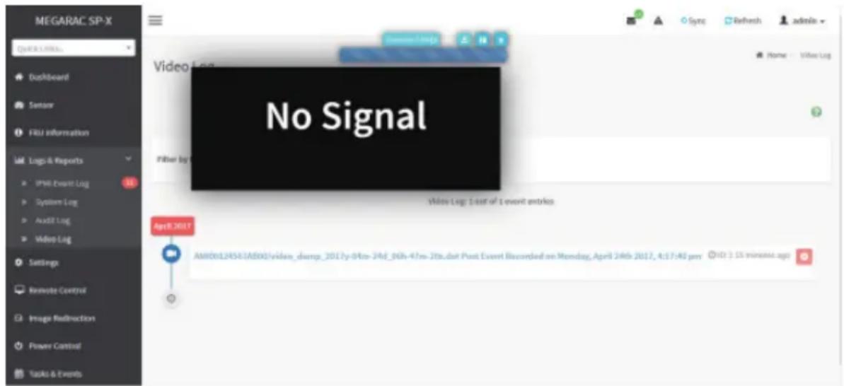
text_image
MEGARAC SP-X Quick URL Dashboard Sentan F&I information Logs & Reports IPMB Event Log System Log Audit Log Video Log Settings Reboot Control Image Redirection Power Control Tasks & Events Video Log: 1 out of 1 event entries No Signal Filter by: Video Log: 1 out of 1 event entries April 2017 AMIDXLE456TABXX/video_dump_2017y-04m-24M_06h-47m-28b.dat Post Event Recorded on Monday, April 24th 2017, 4:57:40 prr (ND) : 15 minutes ago
Video will be allowed to play/download only if file size is lesser than 40MB. Browsers have various memory restrictions, due to this browser cannot store and process data greater than 40MB (approximately). If file size is greater than 40MB, user will be notified with a message to use Java player Application.
2-6 Settings
This group of pages allows you to access various configuration settings. A screenshot of Configuration Group menu is shown below.
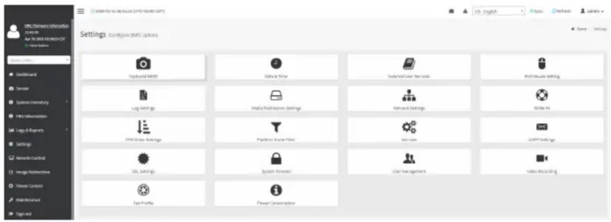
text_image
EMG Networks Information 11:43:00 Apr 30 2003 HORIZON-5CF Home Connection Settings Configure EMFG Options Trajectory Monitoring Data & Timer Industrial User Services EMG Mobile Setting Log Settings Media Resource Settings Network Settings Write-in PWM Order Settings Platform Online Filter Services CDSP Settings SSL Settings System Forecasts User Management Video Recording Fan Profile Power ConsumptionA detailed description of the Settings menu is given below.
2-6-1 Captured BSOD
This page displays a snapshot of the blue screen captured if the host system crashed since last reboot. A screenshot of Captured BSOD is shown below.

text_image
MEGARAC SP-X - New Start Menu Options ( ) Your Office Quick Links... Dashboard Sensor System Inventory FATU Information Logs & Reports Settings Remote Control Image Instruction Power Control Maintenance Sign-out Captured BSOD Last BSOD Screen Captured online.fly.Cali View Search Summary Help xcr@snidges - rsv@snidges-4
Note: KVM service should be enabled to display the BSOD screen. KVM Service can be configured under Settings->Services->KVM.
2-6-2 Date & Time
This field is used to set the date and time on the BMC. A Sample screenshot of Date & Time is shown below.
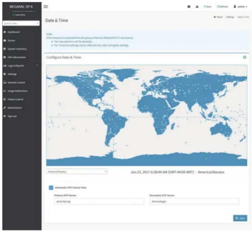
text_image
MEGARAC SP-X MapReduce Quick Update Default Server Systems Inventory FBU Information Logs & Reports Settings Remote Control Image Redirection Power Control Maintenance Sign out Date & Time Configure Date & Time Note: (If this instance is selected from the group of Manual offset (GMT/ETC Simulated): • The step selection will be discontinued. • The Timeframe settings will be affected only after saving the settings. America/Mapless Jun 23, 2017 6:38:44 AM (GMT-04:00 AMT) - America/Manaus Automatic: SFTP Date & Time Primary SFTP Server port.litp.org Secondary SFTP Server time.mst.gov SaveThe Date & Time section consists of the following fields:
Configure Date & Time: Displays Time zone list containing the UTC offset along with the locations and Navigational line to select the location which can be used to display the exact local time.
Select Time Zone: This field is used to set the date and time on the BMC.
Automatic Date & Time: To automatically synchronize Date and Time with the NTP Server.
Primary NTP Server: To configure a primary NTP server to use when automatically setting the date and time.
Secondary NTP Server: To configure a secondary NTP server to use when automatically setting the date and time.
Save: To save the configured settings.

Note: If the timezone is selected as Manual Offset, the map selection will be disabled.
the Time-Zone settings will be reflected only after saving the settings.
Procedure
- Select the Timezone location either using drop down or Map.
- Enable Automatic Date & Time option to enable/disable the use of NTP servers to automatically set the date and time.
- In the Primary NTP Server and Secondary NTP Server fields, specify the NTP servers of the device respectively.

Note: Secondary NTP server is optional field. If the Primary NTP server is not working fine, then the Secondary NTP Server will be used.
- Click Save button to save the settings.
2-6-3 External User Services
LDAP/E-Directory Settings
The Lightweight Directory Access Protocol (LDAP)/E-Directory Settings is an application protocol for querying and modifying data of directory services implemented in Internet Protocol (IP) networks.
In Web GUI, LDAP is an Internet protocol that BMC can use to authenticate users. If you have an LDAP server configured on your network, you can use it as an easy way to add, manage and authenticate BMC users. This is done by passing login requests to your LDAP Server. This means that there is no need to define an additional authentication mechanism, when using the BMC. Since your existing LDAP Server keeps an authentication centralized, you will always know who is accessing the network resources and can easily define the user or group- based policies to control access.
To open External User Services page, click Settings > External User Services from the menu bar. A sample screenshot of External User Services page is shown below.
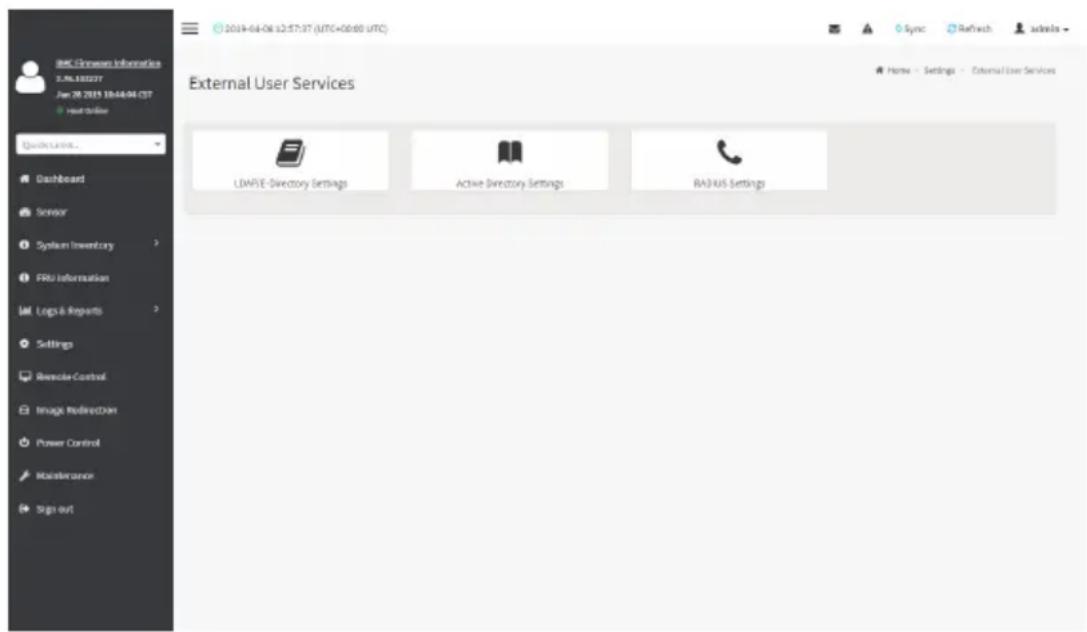
text_image
BAC-Chrome Information 2.NL10227 Jun 28 2015 10:44:04 CST Home Online Quick Launch... Dashboard Sensor System Inventory FRU Information Log & Reports Settings Remote Control Image RedirectView Power Control Maintenance Sign out External User Services LDA/FIE-Directory Settings Active Directory Settings RADIUS Settings Sync Reftech ackela Name - Settings - External User ServicesTo open LDAP/E-DIRECTORY Settings page, click Settings > External User Services > LDAP/E-Directory Settings from the menu bar.
A sample screenshot of External User Services page is shown below.
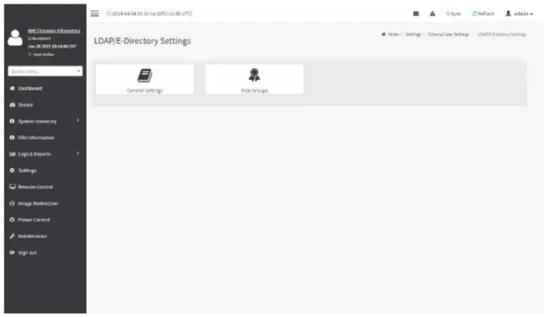
text_image
2019-04-04 01:31:14 (UTC-15:00 UTC) Sync Refresh admin Quick Links... Dashboard Sensor System Inventory FRU Information Mail Logs & Reports Settings Remote Control Image RedirectBox Power Control Maintenance Sign out LDAP/E-Directory Settings General Settings Role GroupsThe fields of LDAP/E-Directory Settings page are explained below.
General Settings: To configure LDAP/E-Directory Settings. Options are Enable LDAP/E-Directory Authentication, IP Address, Port and Search base.
Role Groups: To add a new role group to the device. Alternatively, double click on a free slot to add a role group.
Procedure
- In the LDAP/E-Directory Settings page, click General Settings. A sample screenshot of General LDAP Settings page is given below.
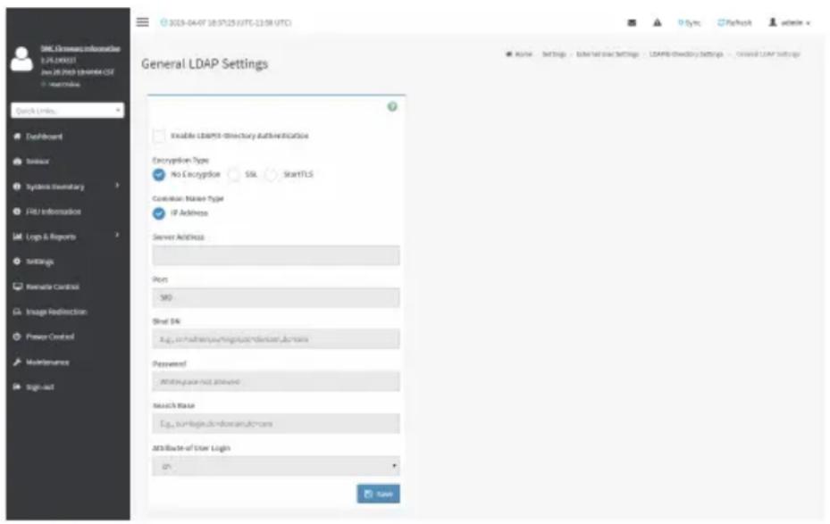
text_image
DNS: General Information 2.2.PILINVEST Jun 01 (2013) Enterprise CSE User Belize Quick Link Dashboard Inkware Systems Inventory FSL Information Logs & Reports Settings Renewable Cardinal Image Redirection Power Control Maintenance Stage-out General LDAP Settings Enable LDAP-Directory Authentication Encryption Type No Encryption SSL StartTLS Common Name Type IP Address Server Address Port SRS Skull OK Eup, on/without any/unknown/unknown domains Password: Writing place not allowed Search Base Eup, on/without any/unknown/unknown domains Attribute-of User Login on Save- Click Enable LDAP/E-Directory Authentication, to enable LDAP/E-Directory Settings.

Note: Configure proper port number, when SSL is enabled.
- Select the Common Name Type as IP Address.
- Enter the IP address of LDAP server in the Server Address field.

Note: IP Address made of 4 numbers separated by dots as in 'xxx.xxx.xxx.xxx'.
Each Number ranges from 0 to 255.
First Number must not be 0.
Supports IPv4 Address format and IPv6 Address format.
Configure FQDN address, when using StartTLS with FQDN.
- Specify the LDAP Port in the Port field.

Note: Default Port is 389. For SSL connections, default port is 636. The Port value
ranges from 1 to 65535.
- Specify the Bind DN that is used during bind operation, which authenticates the client to the server.

Note: Bind DN is a string of 4 to 64 alpha-numeric characters.
It must start with an alphabetical character.
Special Symbols like dot(.), comma(,), hyphen(-), underscore(_) , equal-to(=) are allowed.
Example: cn=manager, ou=login, dc=domain, dc=com
- Enter the password in the Password field.

Note: Password must be at least 1 character long.
Blank space is not allowed
This field will not allow more than 48 characters.
- Enter the Search Base. The Search base allows the LDAP server to find which part of the external directory tree to be searched. The search base may be something equivalent to the organization, group of external directory.

Note: Search base is a string of 4 to 63 alpha-numeric characters.
must start with an alphabetical character.
Special Symbols like dot(.), comma(,), hyphen(-), underscore(_) , equal-to(=) are allowed.
Example: ou-login, dc-domain, dc-com
- Select Attribute of User Login to find the LDAP/E-Directory server which attribute should be used to identify the user.

Note: It only supports cn or uid.
- Select CA Certificate File from the Browse field to identify the certificate of the trusted CA certs.
- Select the CA Certificate File to find the client certificate filename.
- Select Private Key to find the client private key filename.

Note: All the 3 files are required, when StartTLS is enabled.
- Click Save to save the settings.
To add a new Role Group
- In the LDAP/E-Directory Settings page, click Role Groups and select a blank row.
- Click Add Role Group or alternatively double click on the blank row to open the Add Role group page as shown in the screenshot below.

text_image
MEGARAC SP-X @ host Office Role Groups Group Name Group Domains cg_ikmDvrsam Group Privilege User Details Send- In the Group Name field, enter the name that identifies the role group.

Note: Role Group Name is a string of 255 alpha-numeric characters.
pecial symbols hyphen and underscore are allowed.
- In the Group Domain field. Enter the Role Group Domain where the role group is located.

Note: Domain Name is a string of 4 to 64 alpha-numeric characters.
must start with an alphabetical character.
Special Symbols like dot(.), comma(,), hyphen(-), underscore(_) , equal-to(=) are allowed.
Example: cn=manager, ou=login, dc=domain, dc=com
- In the Group Privilege field, enter the level of privilege (User, Administrator, Operator, None) to assign to this role group.
- Select one or both of the required options
- KVM Access
- VMedia Access
- Click Save to save the new role group and return to the Role Group List.
Active Directory Settings
An active directory is a directory structure used on Microsoft Windows based computers and servers to store information and data about networks and domains. An active directory (sometimes referred to as AD) does a variety of functions including the ability to provide information on objects. It also helps to organize these objects for easy retrieval and access, allows access by end users and administrators and allows the administrator to set security up for the directory.
Active Directory allows you to configure the Active Directory Server Settings. The displayed table shows any configured Role Groups and the available slots. You can modify, add or delete role groups from here. Group domain can be the AD domain or a trusted domain. Group Name should correspond to the name of an actual AD group.
Note: To view the page, you must be at least a User and to modify or add a group, you must be an Administrator.
To open Active Directory Settings page, click Settings > External User Settings > Active Directory from the menu bar. A sample screenshot of Active Directory Settings page is shown below.
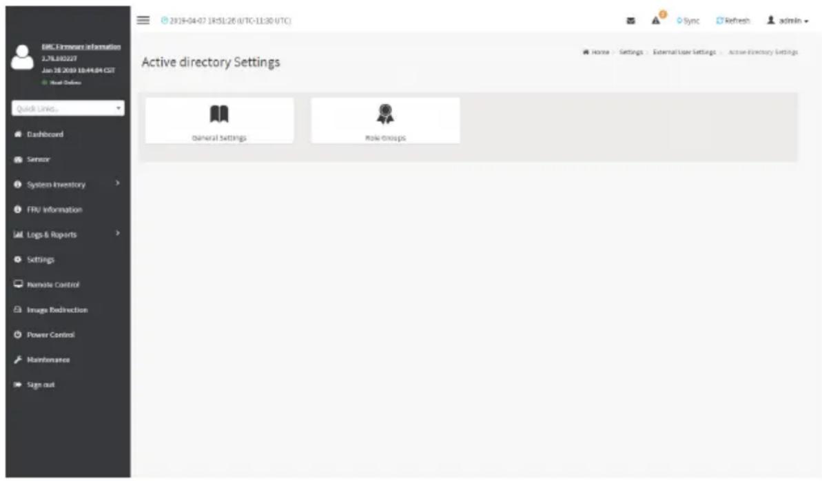
text_image
BMC Software Information 1.7L80227 Jan 18 2019 10:44:04 CST Head Online Quick Links. Dashboard Sensor System Inventory FRU Information Logs & Reports Settings Remote Control Image Redirection Power Control Maintenance Sign out Active directory Settings General settings Make groups Sync Refresh admin Home - Settings - External User Settings - Active Directory SettingsThe fields of Active Directory page are explained below.
General Settings: This option is used to configure Active Directory General Settings. Options are Enable Active Directory Authentication, Secret User Name, Secret Password, User Domain name, and up to three Domain Controller Server Addresses.
Role Groups: To add a new role group to the device. Alternatively, double click on a free slot to add a role group.
Procedure
Entering the details in General Active Directory Settings page:
- Click on General Settings to open the General Active Directory Settings page.

text_image
EMC-Formware Information 1.76.80227 Jan 18 2019 10:44:04 CST Host Online Quick Links... Dashboard Sensor System Inventory FRU Information ML Logs & Reports Settings Remote Control Image Redirection Power Control Maintenance Sign out General Active Directory Settings Enable Active Directory Authentication Secret Username Secret Password User Domain Name Domain Controller Server Address 1 Domain Controller Server Address 2 Domain Controller Server Address 3 Save- In the Active Directory Settings page, check or uncheck the Enable Active directory Authentication check box to enable or disable Active Directory Authentication respectively.

Note: If you have enabled. Active Directory Authentication, enter the required information access the Active Directory server.
- Specify the Secret user name and password in the Secret User Name and Secret Password fields respectively.

Note: Secret username/password for AD is not mandatory. When secret username & password is empty, Authentication fails will be always treated as Invalid Password error.
For Invalid Password error PAM will not try other Authentication Methods. So it is recommended to keep AD in the last location in PAM order.
User Name is a string of 1 to 64 alpha-numeric characters.
It must start with an alphabetical character.
It is case-sensitive.
Special characters like comma, period, colon, semicolon, slash, backslash, square brackets,
Blank space is not allowed, angle brackets, pipe, equal, plus, asterisk, question mark,
ampersand, double quotes, space are not allowed.
Password must be at least 6 character long and will not allow more than 127 characters.
- Specify the Domain Name for the user in the User Domain Name field. E.g. MyDomain.com
- Configure IP addresses in Domain Controller Server Address1, Domain Controller Server Address2 and Domain Controller Server Address3

Note: IP address of Active Directory server: At least one Domain Controller Server dress must be configured. IP Address made of 4 numbers separated by dots as in "xxx.xxx.xxx.xxx".
Each number ranges from 0 to 255.
First number must not be 0.
Domain Controller Server Addresses will supports IPv4 Address format and IPv6 Address format.
- Click Save to save the entered settings and return to Active Directory Settings page.
Role Groups
To open Role Group page, click Settings > External User Settings > Active Directory > Role Groups from the menu bar. A sample screenshot of Role Groups page is shown below.

text_image
BMC Firmware Information 1.76.830227 Jan 18 2019 18:44:04 CST Host Online Quick LIVNS... Dashboard Senior System Inventory FRU Information Logs & Reports Settings Remote Control Images Redirection Power Control Maintenance Sign out Role Groups None None None None NoneThe fields of Role Group page are explained below.
Role Group Name: The name that identifies the role group in the Active Directory.

Note: Role Group Name is a string of 64 alpha-numeric characters.
Special symbols hyphen and underscore are allowed.
Group Name: This name identifies the role group in Active Directory.

Note: Role Group Name is a string of 64 alpha-numeric characters.
Special symbols hyphen and underscore are allowed.
Group Domain: The domain where the role group is located.

Note: Domain Name is a string of 255 alpha-numeric characters.
Special symbols hyphen, underscore and dot are allowed.
Group Privilege: The level of privilege to assign to this role group.
KVM Access: To provide access to KVM for AD authenticated role group user.
VMedia Access: To provide access to VMedia for AD authenticated role group user.
To add a new Role Group
- In the Active Directory Settings page, select a Role Group and click Add Role Group or alternatively double click on the blank row to open the Add Role group page as shown in the screenshot below.

text_image
2018-04-07 18:01:39 (UTC-11:30 UTC) Role Groups Group Name: Group Domains eg, MyCovdcin.com Group Privilege KVM Access Vehicle Access Sign-out- In the Group Name field, enter the name that identifies the role group in the Active Directory.

Note: Role Group Name is a string of 64 alpha-numeric characters.
Special symbols hyphen and underscore are allowed.
- In the Group Domain field, enter the domain where the role group is located.

Note: Domain Name is a string of 255 alpha-numeric characters. - Special symbols /phen, underscore and dot are allowed.
-
In the Group Privilege field, enter the level of privilege to assign to this role group.
-
Select the required options
- KVM Access
- VMedia Access
- Click Save to add the new role group and return to the Role Group List.
To Delete a Role Group
-
In the Role Groups Page, select the row that you wish to delete
-
Click Delete Role Group.
RADIUS Settings
RADIUS is a modular, high performance and feature-rich RADIUS suite including server, clients, development libraries and numerous additional RADIUS related utilities.
In Web GUI, this page is used to set the RADIUS Authentication.
To open RADIUS Settings page, click Settings > External User Settings > RADIUS Settings from the menu bar. A sample screenshot of RADIUS Settings page is shown below.
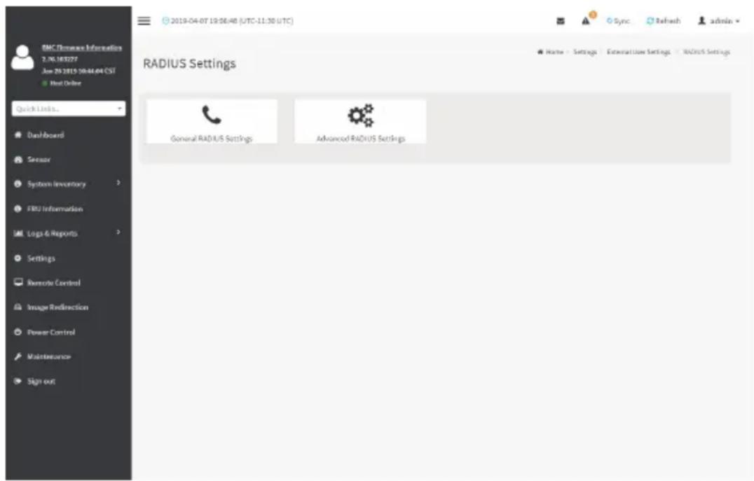
text_image
RMC Features Information 2.06.18/2027 Jun 29 2019 10:44:04 CST Hot Online Quick Links... Dashboard Sensor System Inventory FAS Information Logs & Reports Settings Remote Control Image Redirection Power Control Maintenance Sign out 2019-04-07 19:06:40 (UTC-11:30 UTC) RADIUS Settings General RADIUS Settings Advanced RADIUS Settings Sync Refresh admin Name - Settings | External User Settings - RADIUS SettingsThe fields of General RADIUS Settings page are explained below.
Enable RADIUS Authentication: Option to enable/disable RADIUS authentication.
Server Address: The IP address of RADIUS server.

Note: IP Address (Both IPv4 and IPv6 format).
DN (Fully Qualified Domain Name) format.
Port: The RADIUS Port number.

Note: Default Port is 1812.
Port value ranges from 1 to 65535.
Secret: The Authentication Secret for RADIUS server.

Note: This field will not allow more than 31 characters.
Secret must be at least 4 characters long.
Blank space is not allowed.
Enable KVM Access: This field provides access to KVM for RADIUS authenticated users.
Enable VMedia Access: This field provides access to VMedia for RADIUS authenticated users.
Save: To save the configured settings.
Procedure
- Enable the RADIUS Authentication check box to authenticate the RADIUS.
- Click Advanced RADIUS Settings. This opens the Radius Authorization window as shown below.
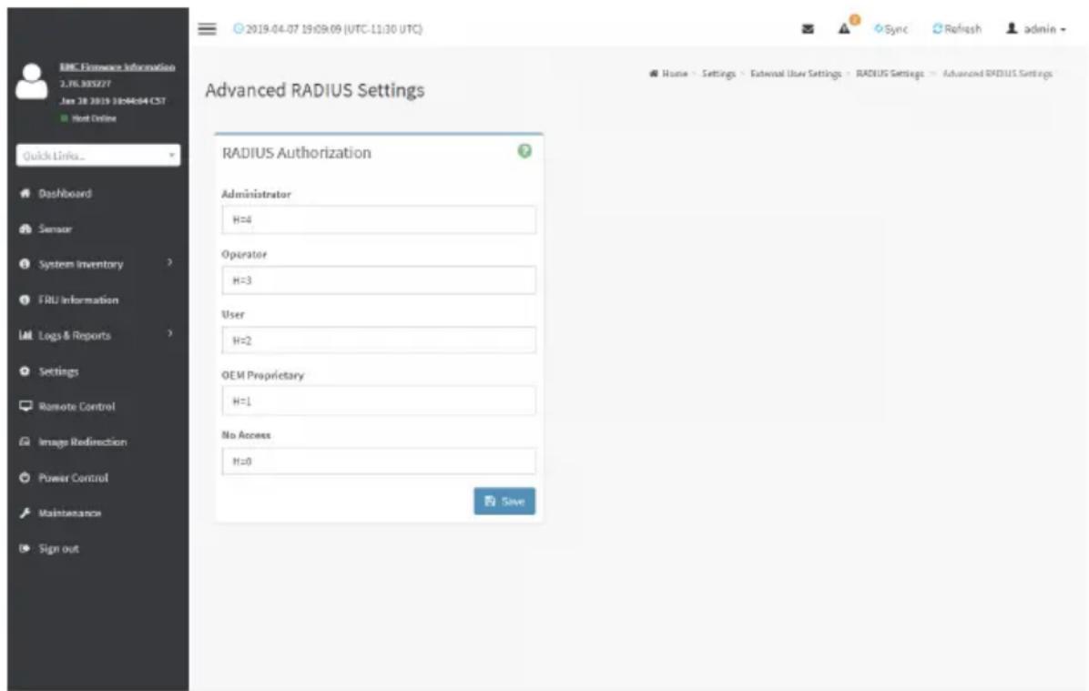
text_image
EMC Finance Information 2.TK 305277 Jan 18 2019 18:04:04 CST Next Online Quick Links... Dashboard Sensor System Inventory FRU Information Logs & Reports Settings Remote Control Image Redirection Power Control Maintenance Sign out Advanced RADIUS Settings RADIUS Authorization Administrator H=4 Operator H=3 User H=2 OEM Proprietary H=1 No Access H=0 Save Sync Refresh admin Home - Settings - External User Settings - RADIUS Settings - Advanced RADIUS Settings
Note: For Authorization Purpose, configure the Radius user with Vendor Specific Attribute in Server side.
Example: 1
testadmin Auth-Type: =PAP, Cleartext-Password:="admin"
Auth-Type: =PAP, Vendor-Specific="H=4"
Example: 2
test operator Auth-Type: = PAP, Cleartext-Password: = "operator"
Auth-Type: =PAP, Vendor-Specific="H=3"
If you change the Vendor-Specific value in server then you should change the same values in this page.
- Click Save to save the changes made.
2-6-4 KVM Mouse Settings
In BMC Web GUI, Redirection Console handles mouse emulation from local window to remote screen in either of three methods. User has to be an Administrator to configure this option. To view the Supported Operating Systems for Mouse Mode, click Mouse Mode.
To open KVM Mouse setting page, click Settings >KVM Mouse Setting from the menu bar.
A sample screenshot of KVM Mouse Settings page is shown below.

text_image
KVM Mouse Setting Mouse Mode Configuration Mouse Mode Relative Positioning (Linux) Absolute Positioning (Windows) Other Mode (SLES-11 OS Installation) SaveThe fields of KVM Mouse Settings page are explained below.
Relative Positioning (Linux): Relative mode sends the calculated relative mouse position displacement to the server.
Absolute Positioning (Windows): The absolute position of the local mouse is sent to the server. Other Mode (SLES-11 OS Installation): To have the calculated displacement from the local mouse in the center position sent to the server.
Save: To save the current changes.
Procedure
- Choose either of the following as your requirement:
- Set mode to Absolute

Note: Applicable for all Windows versions, versions above RHEL6, and versions above FC14
- Set mode to Relative

Note: Applicable for all Linux versions, versions less than RHEL6, and versions less FC14
- Mode to Other Mode

Note: Recommended for SLES-11 OS Installation
- Click Save button to save the changes made.
2-6-5 Log Settings
In BMC Web GUI, System and Audit log page displays a list of system logs and audit logs occurred in this device.
To open Log Settings page, click Settings > Log Settings from the menu bar. A sample screenshot of Log Settings page is shown below.
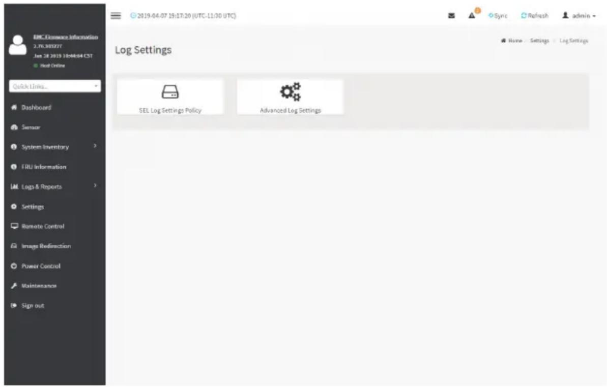
text_image
EMC Finance Information 2.76.305277 Jun 18 2019 30:04:04 CST ● Next Online Quick Links... Dashboard Sensor System Inventory FRU Information Logs & Reports Settings Remote Control Image Redirection Power Control Maintenance Sign out 2019-04-07 19:17:20 (UTC-11:30 UTC) Log Settings SEL Log Settings Policy Advanced Log Settings Sync Refresh admin Home Settings Log SettingsThe fields of Log Settings page are explained below.
SEL Settings Policy
To open SEL Settings Policy page, click Settings > Log Settings > SEL Settings Policy from the menu bar. A sample screenshot of SEL Settings Policy page is shown below.
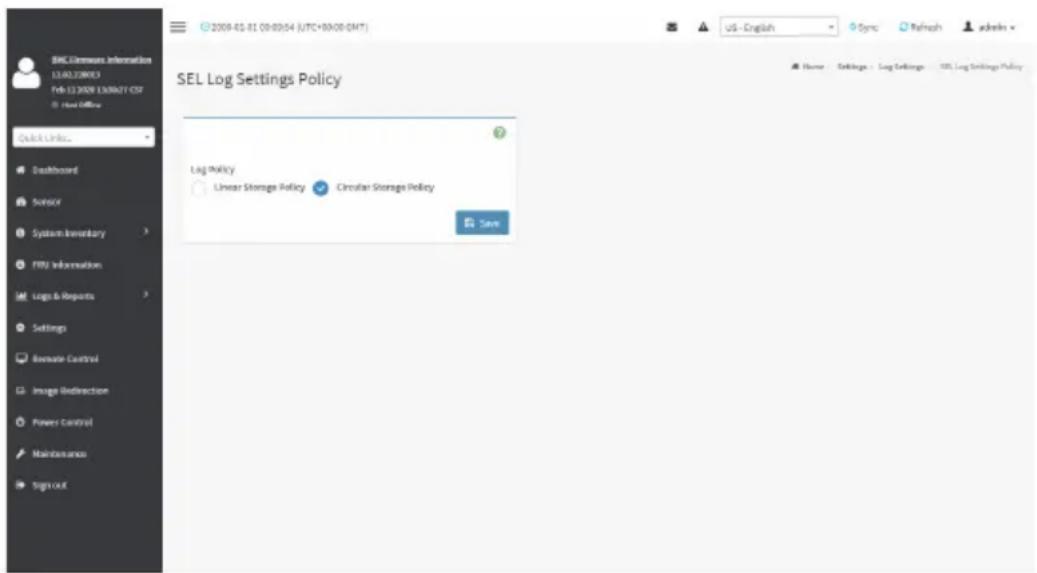
text_image
SEL Log Settings Policy Log Policy Linear Storage Policy Circular Storage Policy SaveAdvanced Log Settings
To open Advanced Log Settings page, click Settings > Log Settings > Advanced Log Settings from the menu bar. A sample screenshot of Advanced Log Settings Policy page is shown below.
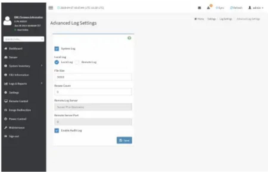
text_image
EMC Information Information 2.PIL 900027 June 26, 2019 (8:45:44 UTC 01:30 UTC) Host Online Quick Info... Dashboard Server System Inventory FBU Information Logs & Reports Settings Reiterate Control Image Radirection Power Control Maintenance Sign out Advanced Log Settings System Log Local Log Local Log Remote Log File Size 50000 Rotate Count 9 Remote Log Server Server Port Monitoring Reiterate Server Port 0 Enable Audit Log SaveThis page is used to configure the log policy for the event log. The fields are as follows.
Enable System Log: This field is to enable or disable the System Logs.
Location: Specifies the Location for system logs, whether it should be preserved in a Local Log or on a Remote Log.

Note: Local file resides at /var/log/
File Size: This field is to specify the size of the file in bytes if the selected log type is local.

Note: Size ranges from 3 to 65535. Log files are rotated when they grow bigger than
size bytes mentioned, with regards for the last rotation time interval (1 minute).
Rotate Count: To back up the log information in back up files.

Note: Values supported are 0 and 1.
When log information exceeds the file size, the old log information is automatically moved to back up files based on the rotate count value. If rotate count is zero, then old log information gets cleared permanently.
File Size and Rotate Count options will be available only when Local Log is enabled.
Remote Log Server: This field is to specify the Remote server address to log the system events.

Note: Server address will support the following:
TPv4 address format.
PQDN (Fully qualified domain name) format.
Remote Server Port: This field is to specify the Remote Server port address to log the system events.

Note: Remote Log Server and Remote Server Port options will be available only when note Log is enabled.
Enable Audit Log: To enable or disable the audit log.
Save: To save the current changes.
Procedure
- In the System Log field, enable or disable the option.
- Select the Log type: Local Log or Remote Log.
- If Local log is selected, enter the file size in the File Size field and rotate count in the Rotate Count field.

Note: If Remote log is selected, the fields file size and rotate count need not be mentioned.
- If remote log is selected specify the Server Address of the remote server, where the system events are logged.
- In the Audit Log field, check or uncheck the Enable option as desired.
- Click Save to save the changes.
Steps to configure the remote server to enable syslogging

Note: This example uses FC13 as the remote machine to log syslog.
FC machine, disable the following lines for UDP in /etc/rsyslog.conf:
- MODLOAD imudp
- UDPSERVER 514
2-6-6 Media Redirection Settings
This page is used to configure the media into BMC for redirection. To open Media Redirection page, click Settings > Media Redirection Settings from the menu bar.
A sample screenshot of Media Redirection page is shown below.
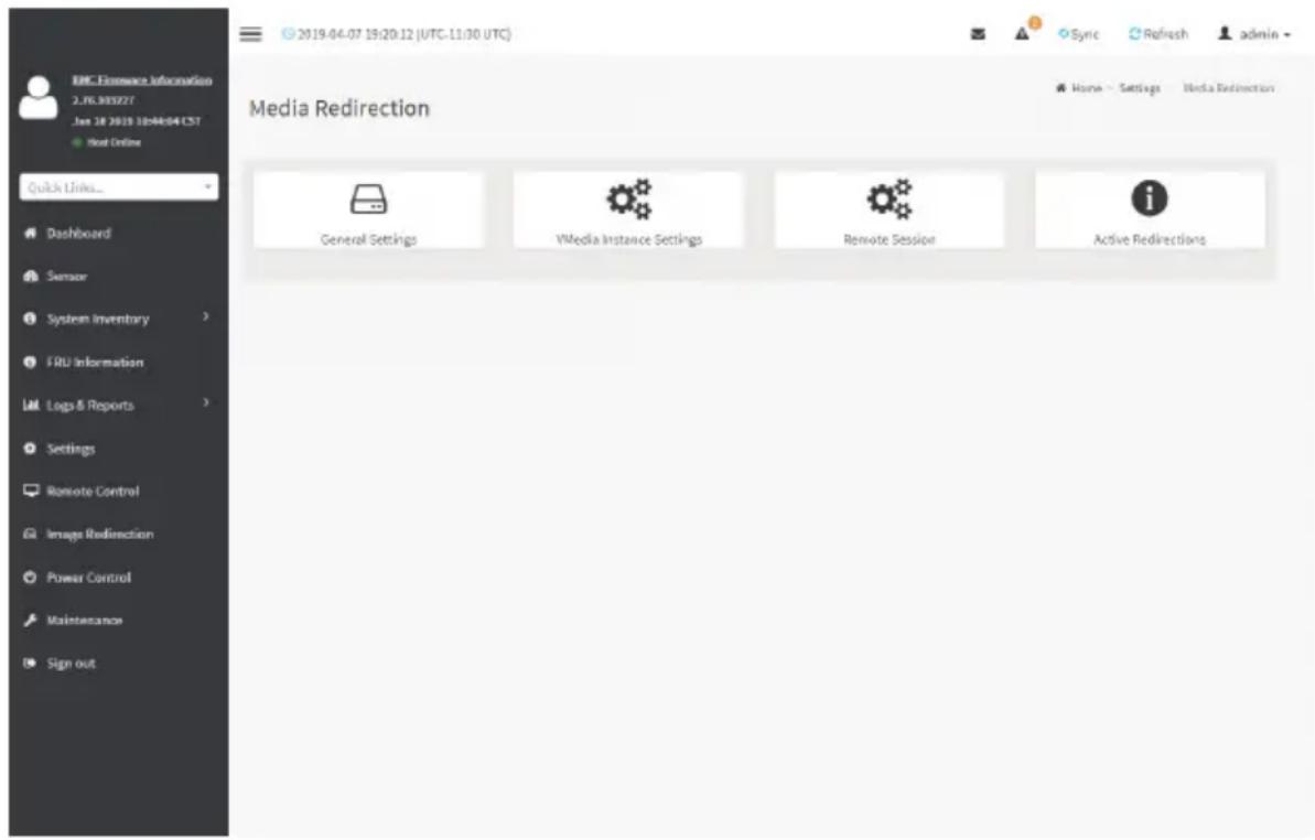
text_image
EMC Infrastructure Information 2.76.905277 Jun 18 2019 30:04:04 CST Hot Online Quick Links... Dashboard Sensor System Inventory FRU Information Logs & Reports Settings Remote Control Image Redirection Power Control Maintenance Sign out 2019-04-07 19:20:12 (UTC-11:30 UTC) Sync Refresh admin Media Redirection General Settings VMedia Instance Settings Remote Session Active RedirectionsThe fields of Media Redirection page are explained below.
- General Settings
• VMedia Instance Settings - Remote Session
• Active Redirections
General Settings
This option is used to configure General Media Settings.
To open General Media Settings section, click Settings > Media Redirection Settings > General Settings.

text_image
EMC Finance Information 2.76.905227 Jun 18 2019 10:04:04 CST ■ Not Online Quick Links... Dashboard Sensor System Inventory FRU Information Logs & Reports Settings Remote Control Image Redirection Power Control Maintenance Sign out 2019-04-07 19:20:49 (UTC-11:30 UTC) Sync Refresh admin General Settings Remote Media Support Mount CD/DVD Mount Handdusk SaveRemote Media Support: To enable or disable Remote Media support, check/uncheck the 'Enable' check box.
If it is selected, then the following Remote Media types will be displayed.
- Mount CD/DVD
- Mount Harddisk
On selecting the individual media types, its respective configurations will be displayed. You can configure different settings for different Remote Media types. A sample screenshot of General Settings page is shown below.

text_image
BMC Firmware Information 12.42.05 Apr 30 2020 16:38:29 CST Host Online Quick Links... Dashboard Sensor System Inventory FRU Information Logs & Reports Settings Remote Control Image Redirection Power Control General Settings Remote Media Support Mount CD/DVD Mount Harddisk Server Address for Harddisk Images Server IP or Host name Path in server eg./opt/bmc/nfs Share Type for Harddisk nfs cifs HTTP Domain Name
Note: You can also select all the media types simultaneously.
Server Address for CD/DVD Images: Displays the address of the server where the remote media images are stored.
Same settings for Harddisk Images: Enable/Disable to select same media type data configurations for all the remote media types.
Mount Harddisk: Enable/Disable to Mount Harddisk.
Server Address for Harddisk Images: Address of the server where the remote media images are stored.
Path in server: Source path to the remote media images.
Share Type for Harddisk: To Select Share Type for Floppy.
Domain Name, Username, and Password: If share Type is Samba(CIFS), then enter user credentials to authenticate on the server.
VMedia Instance Settings
This page is used to configure Virtual Media device settings. To open VMedia Instance Settings page, click Settings > Media Redirection Settings > VMedia Instance Settings from the menu bar.
A sample screenshot of VMedia Instance Settings page is shown below.

text_image
DHC Firmware Information 12.42.05 Age 30-2020 16:38:20 CST Host Online Quick Links. Dashboard Sensor System Inventory FRU Information Logs & Reports Settings Remote Control Image Redirection Power Control Maintenance Sign out CD/DVD device instances 1 Hard disk instances 1 Remote KVM CD/DVD device instances 1 Remote KVM Hard disk instances 1 Power Save Mode Save 2000-01-01 05:14:35 (UTC+00:00 GMT) VMedia Instance SettingsThe following fields are displayed in this page:
CD/DVD device instances: The number of CD/DVD devices supported for Virtual Media redirection.
Harddisk instances: The number of harddisk devices supported for Virtual Media redirection.
Remote KVM CD/DVD device instances: The number of CD/DVD devices supported for KVM Virtual Media redirection.
Remote KVM Hard disk instances: The number of Hard disk devices supported for KVM Virtual Media redirection.
Emulate SD Media as USB disk to Host: To emulate SD Media on BMC as a USB device to Host Server.
Power Save Mode: To enable or disable the virtual USB devices visibility in the host. If this option is enabled, Virtual media devices will be connected to the Host machine only at the instance launching KVM session. If this option is disabled, Virtual media devices will remain connected to the host machine all the time irrespective of KVM session status.
Save: To save the configured settings.

Note: Virtual Media configuration changes will restart all the media services. So configuration changes will be blocked when any active media redirection is present.
Procedure
- Select the number of Floppy devices, CD/DVD devices, Harddisk devices and Remote KVM Floppy, CD/DVD and Hard disk Devices from the respective drop-down list.

Note: Maximum of four devices can be added in Floppy, CD/DVD and Harddisk drives.
- Select the Emulate SD Media as USB disk to Host option to enable/disable the SD card support in the host.
- Check the Power Save Mode option to enable/disable the Virtual USB devices visibility in the host.
- Click Save to save the changes made else click Reset to reset the previously saved values.

Note: When KVM is launched from Standalone Application, if there are two device panels for each device, and when you click the Connect button, then the redirected device panel will be disabled.
Unmounting device will make the driver disconnect device when using Auto Attach. Hence, when unmounting one USB key, the other USB key will be disconnected and then reconnected.
Remote Session
In BMC Web, this page is used to configure Remote Session configuration settings. "KVM Single Port Application" is enabled by default. On disabling, "KVM Single Port Application", "Encrypt H5Viewer KVM packets" will be enabled by default. On enabling "KVM Single Port Application", "Encrypt H5Viewer KVM packets" will be disabled if it is enabled already.
To open Remote Session page, click Settings > Media Redirection Settings > Remote Session from the menu bar.
A sample screenshot of Remote Session page is shown below.
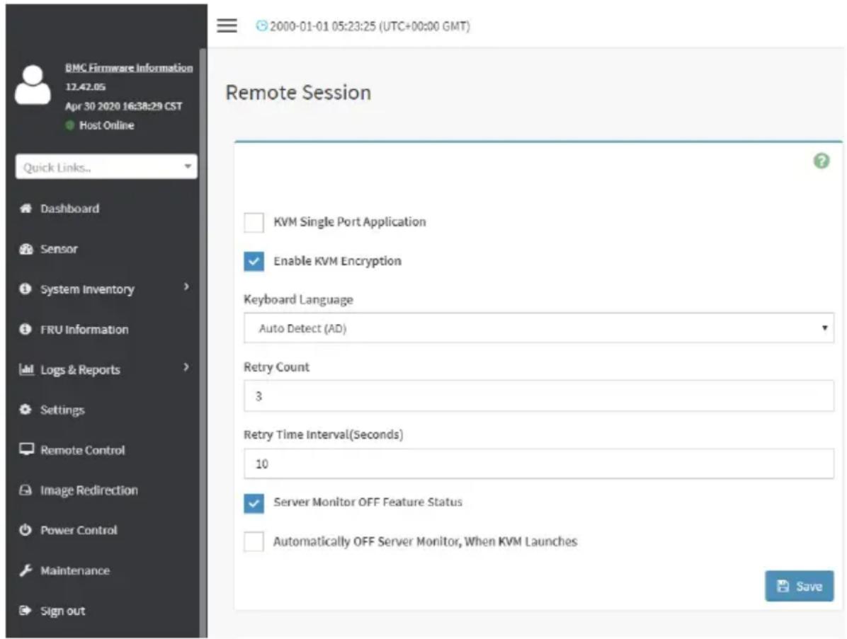
text_image
2000-01-01 05:23:25 (UTC+00:00 GMT) Remote Session KVM Single Port Application Enable KVM Encryption Keyboard Language Auto Detect (AD) Retry Count 3 Retry Time Interval(Seconds) 10 Server Monitor OFF Feature Status Automatically OFF Server Monitor, When KVM Launches SaveThe fields of Configure Remote Session page are explained below.
KVM Single Port Application: To Enable/Disable single port support by runtime. On changing this configuration, KVM and VMedia Sessions will be restarted. If this support is enabled, KVM session will not use its dedicated port whereas both Web and KVM sessions will be established only via Web Port. If this support is disabled, KVM and Web sessions will use their own dedicated ports respectively.
Enable KVM Encryption: To Enable/Disable Enable KVM Encryption for the next redirection session. If KVM Encryption is enabled, the KVM session will use the Secure port which has been configured in Settings -> Services Page.

Note: If “Allow Non-Secure communication for KVM/Media” in the PRJ option is enabled, in KVM/Media can use non-secure communication. i.e. The KVM or Media Encryption be able to disable.
If KVM Encryption is disabled, the KVM session will use the Non-Secure port which has been configured in Settings -> Services Page.

Note: This option is disabled if Single Port is enabled.
Keyboard Language: This option is used to select the keyboard supported languages.
Retry Count: This option is used to retry the redirection session for certain number of attempts.
Retry Time Interval(Seconds): This option is used to give time interval for each attempts.
Server Monitor OFF Feature Status: To enable/disable Server Monitor OFF. If this option is enabled, you can Lock or Unlock the Local host monitor from the remote KVM window. If this option is disabled, you cannot Lock or Unlock the Local host monitor from the remote KVM window.
Automatically OFF Server Monitor, When KVM Launches: To enable/disable Automatically OFF Server Monitor, When KVM Launches.
Save: To save the current changes.

Note: It will automatically close the existing remote redirection either KVM or Virtual via sessions on Single Port enable/Disable.

Note: Installation of Operating System on the servers via BMC CD ISO image over note KVM may take 1 to 2 hours.
Procedure
- Check or uncheck the KVM Single Port Application option to enable Single Port Application support in BMC.
- Choose the Keyboard Language from the list of keyboard supported languages.
- Enter a value in the Retry Count field to set the number of attempts for retrying the redirection session.
- Enter a value in the Retry Time Interval (Seconds) field to give time interval for each attempts.
- Check the Server Monitor OFF Feature Status check box to enable Local Monitor ON/
OFF command during runtime.
-
Check the Automatically OFF Server Monitor, When KVM Launches check box to automatically Lock the local monitor during H5Viewer launch.
-
Click Save to save the current changes.
Active Redirections
This page displays a list of Media which are being redirected currently. It shows current status and other basic information about the Media.
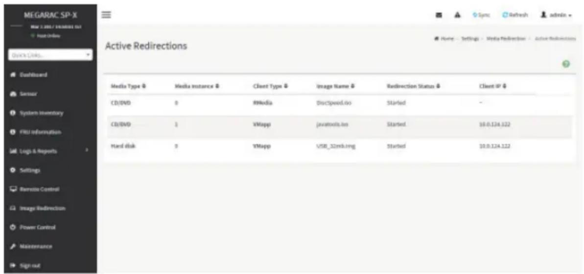
text_image
MEGARAC SP-X MAY 2.205 / VEMERI 01 Host Online Quick Links... Dashboard Server System Inventory FRU Information Log & Reports Settings Remote Control Image Redirection Power Control Maintenance Sign out Active Redirections Media Type ⚙ Media instance ⚙ Client Type ⚙ Image Name ⚙ Redirection Status ⚙ Client IP ⚙ CD/DVD 0 RMedia DiscSpeed.io Started - CD/DVD 1 VMapp javatools.io Started 10.0.124.122 Hard disk 9 VMapp USB_32mb.org Started 10.0.124.122The following fields are displayed in this page.
Media Type: The type Media devices (CD/DVD) supported for Active Redirections.
Media instances: The number of Media devices supported for Active Redirections.
Client Type: The type Media devices (CD/DVD) supported for Active Redirections.
Image Name: The name of Media devices supported image for Active Redirections.
Redirection Status: The status Media for Active Redirections.
Client IP: The IP of the connected Media devices (CD/DVD) supported for Active Redirections.

Note: Local/Remote Media connection will use loopback socket for communication. So symbol will be displayed for loopback ip(127.0.0.1 (or) ::1 ) in media session information page.
2-6-7 Network Settings
The Network Settings page is used to configure the network settings for the available LAN channels. It also allows users to manage the DNS settings or configure Network Controller Sideband Interface of a device. To open the Network Settings page, click Settings > Network Settings from the menu bar.

text_image
EMC Infrastructure Information 2.76.905277 Jun 18 2019 30/04/04 CST ● Host Online Quick Links... Dashboard Sensor System Inventory FRU Information Logs & Reports Settings Remote Control Image Redirection Power Control Maintenance Sign out 2019-04-07 19:26:46 (UTC-11:30 UTC) Sync Refresh admin Network Settings Network IP Settings DNS ConfigurationNetwork IP Settings
To open Network IP Settings page, click Settings > Network Settings > Network IP Settings from the menu bar. A sample screenshot of Network IP Settings page is shown below.

text_image
DRL Software Information 1.PK 302117 Jan 28, 2019 10:00:00:45 File Edit Before USB Lenses DualBoard Sensor System Inventory FXU Information Link Logs & Reports Settings Monstrate Control Image Infrastructure Power Control Maintenance Snapset Network IP Settings Enable LAN LAN Interface band0 MAC Address: 0.6156E(5.901C2) Enable IPv4 Enable IPv4 DHCP IPv4 Address: JL 0.311.323 IPv4 Subnet: 316.255.255.0 IPv4 Gateway: 315.571.263 Enable IPv4 Enable IPv4 DHCP IPv4 Inferc: 0 IPv4 Address: 360 Linux-1234.5078x2.65SoftXscSdc2 Submit Prefix Length: 61 Enable VLAN VLAN ID: 0 VLAN Priority: 0 SaveThe fields of Network IP Settings page are explained below.
Enable LAN: To enable or disable the LAN Settings.
LAN Interface: Lists the LAN interfaces.
MAC Address: This field displays the MAC Address of the device. This is a read only field.
Enable IPv4: This option is to enable/disable the IPv4 settings in the device.
Enable IPv4 DHCP: This option is to enable IPv4 DHCP support for the selected interface.
IPv4 Address, IPv4 Subnet Mask, and IPv4 Default Gateway: These fields are for specifying the static IPv4 address, Subnet Mask and Default Gateway to be configured to the device.

Note: IP Address made of 4 numbers separated by dots as in "xxx.xxx.xxx.xxx".
Each Number ranges from 0 to 255.
First Number must not be 0.
Enable IPv6: To Enable/Disable the IPv6 configuration settings.
Enable IPv6 DHCP: To Enable/Disable the IPv6 settings in the device. It dynamically configures IPv6 address using DHCP (Dynamic Host Configuration Protocol).
IPv6 Index: To specify a static IPv6 Index to be configured to the device. E.g.: 0
IPv6 Address: To specify a static IPv6 address to be configured to the device. E.g.: 2004::2010
Subnet Prefix length: To specify the subnet prefix length for the IPv6 settings.

Note: Value ranges from 0 to 128.
Default Gateway: Specify v6 default gateway for the IPv6 settings.

Note: If core feature IPV6_COMPLIANCE is enabled, the IPV6 default Gateway field will be displayed.
Enable VLAN: To enable/disable the VLAN support for selected interface.
VLAN ID: The Identification for VLAN configuration.

Note: Value ranges from 2 to 4094.
VLAN Priority: The priority for VLAN configuration.

Note:
lue ranges from 0 to 7.
7 is the highest priority for VLAN.
Save: To save the entries.
Procedure
- Check Enable LAN to enable LAN support for the selected interface.
- Select the LAN Interface to be configured.
- Check Enable IPv4 to enable IPv4 support for the selected interface.
- Check Enable IPv4 DHCP to dynamically configure IPv4 address using DHCP.
- If the field is disabled, enter the IPv4 Address, IPv4 Subnet Mask and IPv4 Default Gateway in the respective fields.
- In IPv6 Configuration, if you wish to enable the IPv6 settings, check Enable IPv6.
- If the IPv6 setting is enabled, enable or disable the option Enable IPv6 DHCP.
- If the field is disabled, enter the IPv6 Address, Subnet Prefix length and IPv6 Index in the given field.
- In VLAN Configuration, if you wish to enable the VLAN settings, check Enable LAN.
- Enter the VLAN ID in the specified field.
-
- Enter the VLAN Priority in the specified field.
- Click Save to save the entries.
DNS Configuration
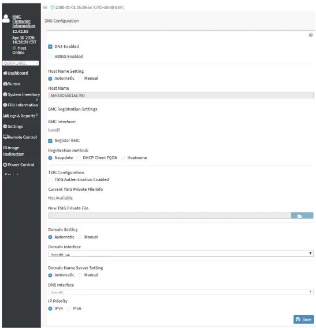
The Domain Name System (DNS) is a distributed hierarchical naming system for computers, services, or any resource connected to the Internet or a private network. It associates the information with domain names assigned to each of the participants. Most importantly, it translates domain names meaningful to humans into the numerical (binary) identifiers associated with networking equipment for the purpose of locating and addressing these devices worldwide. The DNS Server settings page is used to manage the DNS settings of a device.
To open DNS Server Settings page, click Settings > Network Settings > DNS Configuration from the menu bar. A sample screenshot of DNS Configuration page is shown below.
text_image
2000-01-01 05:39:54 (UTC+00:00 GMT) DNS Configuration DNS Enabled mDNS Enabled Host Name Setting Automatic Manual Host Name AMIE0DSSE1AE790 BMC Registration Settings BMC Interface: bond0 Register BMC Registration method: Nsupdate DHCP Client FQDN Hostname TSIG Configuration TSIG Authentication Enabled Current TSIG Private File Info Not Available New TSIG Private File Domain Setting Automatic Manual Domain Interface bond0.v6 Domain Name Server Setting Automatic Manual DNS Interface bond0 IP Priority IPv4 IPv6 Quick Links... Dashboard Sensor System Inventory FRU Information Log & Reports Settings Remote Control File Image Redirection Power ControlDomain Name Service Configuration
DNS Enabled: To enable/disable all the DNS Service Configurations.
mDNS Enable: To enable/disable the mDNS Support Configurations.
Host Name Settings: Choose either Automatic or Manual settings.
Host Name: It displays host name of the device. If the Host setting is chosen as Manual, then specify the host name of the device.

Note: Value ranges from 1 to 64 alpha-numeric characters.
Special characters ‘-’(hyphen) and ‘_’(underscore) are allowed.
It must not start or end with a '-' (hyphen). IE browsers won't work correctly if any part of the host name contain underscore (_) character.
BMC Registration Settings
BMC Interface: Options to register the BMC through the Interfaces (eth0ð1).
Register BMC: To register BMC through registration method.
Registration Method
Options to register the BMC are through NS Update or DHCP Client FQDN or Hostname.
TSIG Configuration
Both: Check this option to modify TSIG authentication for both interfaces.
Eth 0&1:
- TSIG Authentication Enabled: Check this box to enable TSIG authentication while registering DNS via nsupdate. Separate TSIG files can be uploaded for each LAN interface.
- Current TSIG Private File: The information of Current TSIG private file along with its uploaded date/time will be displayed (readonly).
- New TSIG Private File: Browse and navigate to the TSIG private file.

Note: TSIG file should be of private type.
Domain Setting: Select whether the domain interface will be configured manually or automatically.
- Automatic - If you Select Automatic, the Domain Name cannot be configured as it will be done automatically. The field will be disabled.
- Manual - If the Domain setting is chosen as Manual, then specify the domain name of the device.

Note: If you select "Automatic" it displays the Domain Interface option. If
t "Manual" it displays "Domain name".
- Domain Name: It displays the domain name of the device.
Domain Name Server Setting
Automatic - If you select Automatic "DNS Interface" option should be explained.
Manual - Specify the DNS (Domain Name System) server address to be configured for the BMC.
IP Priority:
- If IP Priority is IPv4, it will have 2 IPv4 DNS servers and 1 IPv6 DNS server.
- If IP Priority is IPv6, it will have 2 IPv6 DNS servers and 1 IPv4 DNS server.

Note: This is not applicable for Manual configuration.
DNS Server 1, 2 & 3
To specify the DNS (Domain Name System) server address to be configured for the BMC.

Note: IPv4 Addresses should be given in dotted decimal representation.
Addresses are supported and must be global unicast addresses.
DNS Server Address will support the following:
- IPv4 Address format.
- IPv6 Address format.
Save: To save the current changes.
Procedure
- In Domain Name Service Configuration, Enable DNS Service.
-
Check the option DNS Enabled to enable all the DNS Service Configurations.
-
Choose the Host Name Setting either Automatic or Manual.

Note: If you choose Automatic, you need not enter the Host Name and if you choose equal, you need to enter the Host Name.
-
Enter the Host Name in the given field if you have chosen Manual Configuration.
-
Under Register BMC, choose the BMC's network port to register with DNS settings. Check Register BMC option to register with DNS settings.
-
Nsuchdate - Choose Nsuchdate option to register with DNS server using nsupdate application.
- DHCP Client FQDN - Choose DHCP Client FQDN option to register with DNS Server using DHCP option 81.
- Hostname - Choose Hostname option to register with DNS server using DHCP option 12.

Note: Hostname option should be selected, if the DHCP client FQDN option is not sorted by DHCP server.
-
Check Both option to modify TSIG authentication for both interfaces (eth0&1).
-
In Eth 0&1 TSIG Configuration, Check TSIG Authentication Enabled option to enable/disable TSIG authentication while registering DNS via nsupdate.
-
The current file name will be displayed in Current TSIG Private file info field.
-
To view a new one, click New TSIG private file to browse and navigate to the TSIG private file.
-
In the Domain Settings,
-
Select the domain settings (Automatic or Manual).
-
Enter the Domain Name in the given field if the option "Manual" is being selected in domain settings field.
-
In Domain Name Server Setting,
-
Select the DNS Name Server Setting.
- Choose the IP Priority, either IPv4 or IPv6.
-
Enter the DNS Server address.
-
In DNS Server1, DNS Server2 and DNS Server3, enter the server addresses to be configured for the BMC.
-
Click Save to save the entries.
2-6-8 NVMe MI Management

text_image
NVMe-MI Management NVMe-MI Subsystem NVMe-MI Virtual Product DataNVMe-MI Subsystem Information

text_image
NVMe-MI Subsystem Information NVMe MIO Subsystem Information Port information Subsystem Health Status PhII Set Health Status Change No. of Parts Major Version Minor VersionIn selecting any particular NVMe SSD, the corresponding NVMe SSD Subsystem Information, Port Information, Subsystem Health Status Poll and Set Health Status Change will be displayed. Click on 'Clear All' button to clear all Composite Controller Status Flags at a time under 'Subsystem Health Status Poll' information tab.
Click on 'Clear' button to clear individual Composite Controller Status Flags under 'Set Health Status Change' information tab.
NVMe-MI Vital Product Data
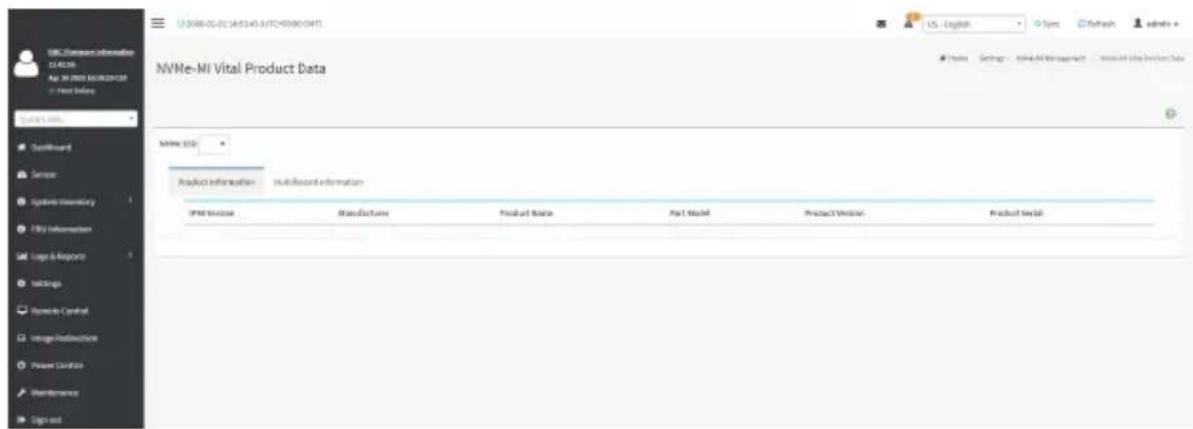
text_image
NVMe-Mi Vital Product Data NVMe 350 Product Information - multisector information IPM Service Manufacture Product Table Part Model Product Version Product Serial US - English Types Pathway admin Hardware Settings - Microsoft Excel Management - Microsoft SQL Server DataOn selecting any particular NVMe SSD, the corresponding SSD's Product Information will be displayed. It displays detailed information like IPMI Version, Product Name, Part Model, Product Version etc.. of the NVMe SSD. On Click of 'Multi Record Information' tab NVMe MultiRecord and NVMe PCIe Port MultiRecord will be displayed.
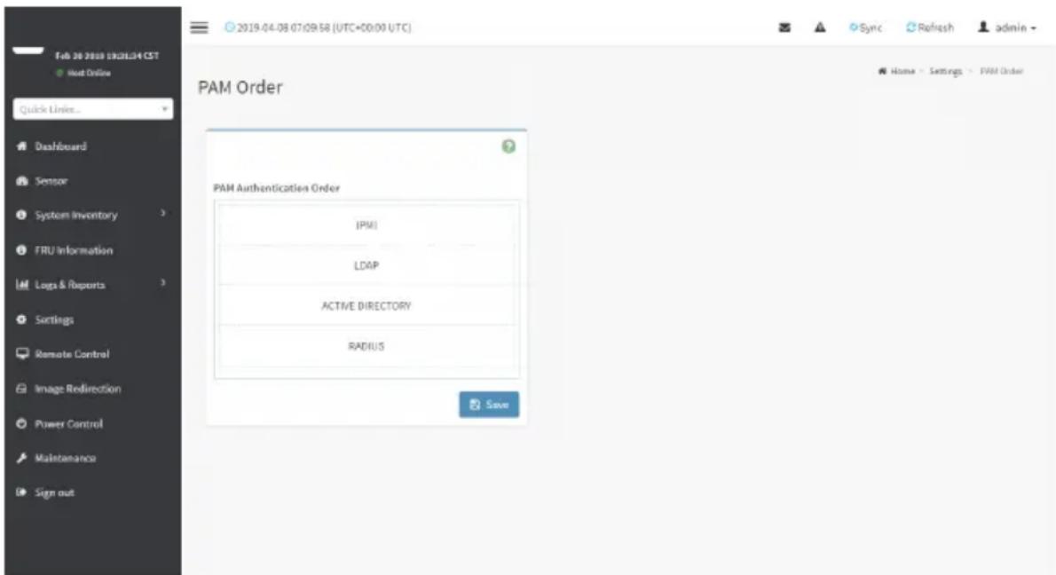
2-6-9 PAM Order Settings
This page is used to configure the PAM ordering for user authentication in to the BMC.
To open PAM Ordering page, click Settings > PAM Order Settings from the menu bar. A sample screenshot of PAM Order page is shown below:
text_image
2019-04-08 07:09:58 (UTC+00:00 UTC) PAM Order PAM Authentication Order IPMI LDAP ACTIVE DIRECTORY RADIUS SaveThe fields of Setttings > PAM Ordering page are explained below.
PAM Module: It shows the list of available PAM modules supported in BMC.

Note: It is recommended to not to keep same username for different PAM modules.
thentication fails, the reason of fail could be invalid User or Invalid Password.
If Radius Authentication fails, we can't differentiate whether it is invalid user or invalid password. So it is always treated as Invalid username error and PAM will try other Authentication Methods.
If AD contains secret username & password as empty, Authentication fails will be always treated as Invalid Password error. For Invalid Password error PAM will not try other Authentication Methods. So it is recommended to keep AD in the last location in PAM order.
Procedure
- Select the required PAM module and click and drag the required PAM module. It can be moved UP or DOWN to change its arrangement order.
- Click Save to save any changes made.

Note: Whenever the configuration is modified, the web server will be restarted matically. Logged-in session will be logged out.
2-6-10 Platform Event Filter
Platform Event Filter (PEF) provides a mechanism for configuring the BMC to take selected actions on event messages that it receives or has internally generated. These actions include operations such as system power-off, system reset, as well as triggering the generation of an alert.
In BMC Web GUI, the PEF Management is used to configure the following:
- Event Filters
- Alert Policies
• LAN Destinations
To open PEF Management Settings page, click Settings > Platform Event Filter from the menu bar. Each tab is explained below.

text_image
DRC History Information 1135649 New 4/2021 2021.4.2.CSF Local media Organ & Controls Launches & Sensors System Inventory FPGA Information Loop & Requests Settings Remote Control Image Reflective Power Control Maintenance Sign out Platform Event Filters Event Protection Next Painting Last Design/Storage Home Settings Platform Event FiltersEvent Filters
A PEF implementation is recommended to provide at least 40 entries in the event filter table. A subset of these entries should be pre-configured for common system failure events, such as over-temperature, power system failure, fan failure events, etc. Remaining entries can be made available for 'OEM' or System Management Software configured events. Note that individual entries can be tagged as being reserved for system use - so this ratio of pre-configured entries to run-time configurable entries can be reallocated if necessary.
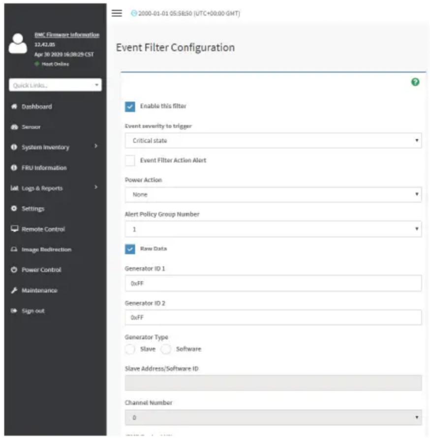
text_image
BMC Fireware Information 12.42.05 Apr 30 2020 16:38:29 CST Host Online Quick Links... Dashboard Sensor System Inventory FRU Information Logs & Reports Settings Remote Control Image Redirection Power Control Maintenance Sign out Event Filter Configuration Enable this filter Event severity to trigger Critical state Event Filter Action Alert Power Action None Alert Policy Group Number 1 Raw Data Generator ID 1 0xFF Generator ID 2 0xFF Generator Type Slave Software Slave Address/Software ID Channel Number 0The fields of Platform Event Filters Tab are explained below.
This page contains Pre-configured 40 Events with PEF IDs.
Procedure
- Click the Event Filters section to configure the event filters in the available slots.
- To Add an Event Filter entry, select a free section to open the Event Filter entry page. A sample screenshot of Event Filter Configuration page is shown below.

text_image
Event Filter Configuration Enable the filter Event security to trigger Critical issues Event Filter Before Alert Power Section None Worst Policy Group Member New Data Controller ID:1 Full Controller ID:2 Full Parameter Type Name Software Store Address/Software ID Channel Number 0 MWD Policy LWP 0 Service type Temperature Service name All Services Event Settings All Settings Service Events Lower Service Critical Coding Line Starting High Lower Threshold Coding Line Starting High Lower Service Security Level Coding Line Starting High Upper Service Interval Coding Line Starting High Lower Threshold Coding Line Starting High Upper Service Resources Code Coding Line Starting High Event Manager 2015 Event Data 1 MWD Work 0 Event Data 2 Compane 1 2015 Event Data 1 Compane 2 0 Event Data 2 MWD Work 0 Event Data 3 Compane 1 2015 Event Data 3 Compane 1 0 Cancel PrintIn the Event Filter Configuration section:
- In Enable this filter, check this option to enable the PEF settings.
• In Event Severity to trigger, select any one of the Event severity from the list. - Check Event Filter Action Alert to enable alerts for event filter actions.
- Select any one of the Power Action either Power down, Power reset or Power cycle from the drop down list
- Choose any one of the configured Alert Policy Group Number from the drop down list.

Note: Alert Policy has to be configured - under Settings->PEF->Alert Policy.

- Check Raw Data option to fill the Generator ID with raw data.
- Generator ID 1 field is used to give raw generator ID 1 data value.
- Generator ID 2 field is used to give raw generator ID2 data value.
Note: In RAW data field, specify hexadecimal value prefix with '0x'.
- In the Event Generator section, choose the event generator as Slave Address - if event was generated from IPMB. Otherwise as System Software ID - if event was generated from system software.
- In the Slave Address/Software ID field, specify corresponding I2C Slave Address or System Software ID.
- Choose the particular Channel Number that event message was received over. Or choose '0' if the event message was received via the system interface, primary IPMB, or internally generated by the BMC.
- Choose the corresponding IPMB Device LUN if event generated by IPMB.
- Select the Sensor Type of sensor that will trigger the event filter action.
• In the SensorName field, choose the particular sensor from the sensor list. - Choose Event Option to be either All Events or Sensor Specific Events.
• In the Sensor Events field, choose the type of event levels. - Event Trigger field is used to give Event/Reading type value.
Note: Value ranges from 1 to 255.

• Event Data 1 AND Mask field is used to indicate wildcarded or compared bits.
Note: Value ranges from 1 to 255.

- Event Data 1 Compare 1 & Event Data 1 Compare 2 fields are used to indicate whether each bit position's comparison is an exact comparison or not.
Note: Value ranges from 1 to 255.

• Event Data 2 AND Mask field is similar to Event Data 1 AND Mask.
• Event Data 2 Compare 1 & Event Data 2 Compare 2 fields are similar to Event Data 1 Compare 1 and Event Data 1 Compare 2 respectively.
• Event Data 3 AND Mask field is similar to Event Data 1 AND Mask.
• Event Data 3 Compare 1 & Event Data 3 Compare 2 fields are similar to Event Data 1 Compare 1 and Event Data 1 Compare 2 respectively.
- Click Save to save the changes and return to event filter list.
- Click Delete to delete the existing filter.
Alert Policies
This page is used to configure the Alert Policy for the PEF configuration. You can add, delete or modify an entry in this page.
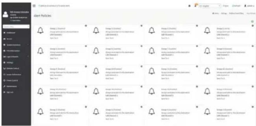
text_image
Alert Policies Group 1 (Warning) Group 2 (Warning) Group 3 (Warning) Group 4 (Warning) Group 5 (Warning) Group 6 (Warning) Group 7 (Warning) Group 8 (Warning) Group 9 (Warning) Group 10 (Warning) Group 11 (Warning) Group 12 (Warning) Group 13 (Warning) Group 14 (Warning) Group 15 (Warning) Group 16 (Warning) Group 17 (Warning) Group 18 (Warning) Group 19 (Warning) Group 20 (Warning) Group 21 (Warning) Group 22 (Warning) Group 23 (Warning) Group 24 (Warning) Group 25 (Warning) Group 26 (Warning) Group 27 (Warning) Group 28 (Warning) Group 29 (Warning) Group 30 (Warning) Group 31 (Warning) Group 32 (Warning) Group 33 (Warning) Group 34 (Warning) Group 35 (Warning) Group 36 (Warning) Group 37 (Warning) Group 38 (Warning) Group 39 (Warning) Group 40 (Warning) Group 41 (Warning) Group 42 (Warning) Group 43 (Warning) Group 44 (Warning) Group 45 (Warning) Group 46 (Warning) Group 47 (Warning) Group 48 (Warning) Group 49 (Warning) Group 50 (Warning) Group 51 (Warning) Group 52 (Warning) Group 53 (Warning) Group 54 (Warning) Group 55 (Warning) Group 56 (Warning) Group 57 (Warning) Group 58 (Warning) Group 59 (Warning) Group 60 (Warning) Group 61 (Warning) Group 62 (Warning) Group 63 (Warning) Group 64 (Warning) Group 65 (Warning) Group 66 (Warning) Group 67 (Warning) Group 68 (Warning) Group 69 (Warning) Group 70 (Warning)The fields of Platform Event Filter - Alert Policies section are explained below.
Policy Group Number: Displays the Policy number of the configuration.
Enable this alert: To enable or disable the policy settings.
Policy Action: To choose any one of the Policy set values (0-5) from the list.
0 - Always send alert to this destination.
1 - If alert to previous destination was successful, do not send alert to this destination. Proceed to next entry in this policy set.
2 - If alert to previous destination was successful, do not send alert to this destination. Do not process any more entries in this policy set.
3 - If alert to previous destination was successful, do not send alert to this destination. Proceed to next entry in this policy set that is to a different channel.
4 - If alert to previous destination was successful, do not send alert to this destination. Proceed to next entry in this policy set that is to a different destination type.
LAN Channel: To choose a particular channel from the available channel list.
Destination Selector: To choose a particular destination from the configured destination list.

Note: LAN Destination has to be configured - under Settings->Platform Event Filters AN Destinations.
Event Specific Alert String: To specify an event-specific Alert String.
Alert String Key: To specify which string is to be sent for this Alert Policy entry.
Save: To save the Alert Policies entries.
Delete: To delete the selected configured Alert Policy.
Procedure
-
In the Alert Policies Section, select the slot for which you have to configure the Alert policy. That is, In the Alert Policies page, if you have chosen Alert Policy Group Number as 4, you have to configure the 4th slot (the slot with Policy Number 4) in the Alert Policy Tab.
-
Select the slot and click on the empty slot to open the Alert Policies page as shown in the screenshot below.

text_image
EMC Wireless Information 3.76.145217 Jun 18 2019 EMISSION CST Next Online Quick Links... Dashboard Searcher System Inventory TRU Information Login & Reports Settings Remote Control Image Realization Power Control Maintenance Sign out Alert Policies Policy Group Number 3 Enable this alert Policy Action Always send alert to this destination LAN Channel 3 Destination Selector 3 Event Specific Alert String Alert String Key Delete Save Sync Refresh admin Names - Settings - Platform Event Filters - Alert Policies - Alert Policies- Select Policy Group Number from the drop-down list.
- Check Enable this alert to enable the policy settings.
- Choose any of the Policy Action from the list.
- Choose particular LAN Channel from the available channel list.
- In the Destination Selector, choose particular destination from the configured destination list.

Note: LAN Destination has to be configured under Settings-> Platform Event Filters-AN Destinations.
That is if you select the number 4 for destination selector in Alert Policy Entry page, then you have to configure the 4th slot (LAN Destination Number 4) in the LAN Destinations tab.
- Enable Event Specific Alert String, if the Alert policy entry is Event Specific.
- In the Alert String Key field, choose any one value that is used to look up the Alert String to send for this Alert Policy entry.

Note: Using Web UI, Alert strings cannot be configured but option for Event Specific port strings can be enabled/disabled. There is an option to select only the alert string keys, but alert strings has to be configured using IPMI Command (Set PEF Config parameter 'Alert String').
- Click Save to save the new alert policy and return to Alert Policy list.
- Click Delete to delete a configuration.
LAN Destinations
This page is used to configure the LAN destination of PEF configuration. A sample screenshot of LAN Destination page is given below.

text_image
LAN Destinations Select the LAN Channel 1 LAN Channels 1 LAN Destination 2 SNRP Tarp Snow Px LAN Channels 2 LAN Destination 3 SNRP Tarp Snow Px LAN Channels 3 LAN Destination 4 SNRP Tarp Snow Px LAN Channels 4 LAN Destination 5 SNRP Tarp Snow Px LAN Channels 5 LAN Destination 6 SNRP Tarp Snow Px LAN Channels 6 LAN Destination 7 SNRP Tarp Snow Px LAN Channels 7 LAN Destination 8 SNRP Tarp Snow Px LAN Channels 8 LAN Destination 9 SNRP Tarp Snow Px LAN Channels 9 LAN Destination 10 SNRP Tarp Snow Px LAN Channels 10 LAN Destination 11 SNRP Tarp Snow Px LAN Channels 11 LAN Destination 12 SNRP Tarp Snow Px LAN Channels 12 LAN Destination 13 SNRP Tarp Snow PxThe fields of Platform Event Filters - LAN Destinations are explained below. Select any empty slot to configure LAN Destinations.
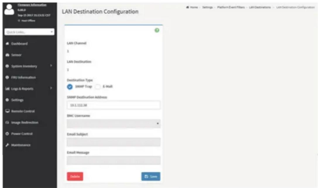
text_image
LAN Destination Configuration LAN Channel 1 LAN Destination 1 Destination Type SNMP Trap E-Mail SNMP Destination Address: 10.1.112.38 BMC Username Email Subject Email Message Delete LoanSelect the LAN Channel: To select the LAN Channel number
LAN Channel: Displays LAN Channel Number for the selected slot (read-only).
LAN Destination: Displays ID for setting Destination Selector of Alert Policy (read-only).
Destination Type: Destination type can be either an SNMP Trap or an E-mail alert. For E-mail alerts, the four fields - SNMP Destination Address, BMC User Name, Email subject and Email message needs to be filled. The SMTP server information also has to be added - under Settings ->SMTP Settings. For SNMP Trap, only the SNMP Destination Address has to be filled.
SNMP Destination Address: If Destination type is SNMP Trap, then enter the IP address of the system that will receive the alert. Destination address will support the following:
- IPv4 address format.
- IPv6 address format.
BMC User Name: If Destination type is Email Alert, then choose the user to whom the email alert has to be sent. Email address for the user has to be configured under Settings-->User Management.
Email Subject & Email Message: These fields must be configured if email alert is chosen as destination type. An email will be sent to the configured email address of the user in case of any severity events with a subject specified in subject field and will contain the message field's content as the email body. These fields are not applicable for 'AMI- Format' email users.

Note: User should be configured under Settings-->User Management
Save: To add a new entry to the device. Alternatively, double click on a free slot. Delete: To delete the selected configured LAN Destination.
Procedure
- In the LAN Destinations section, choose the number of slots to be configured. This should be the same number of slot that you have selected in the Alert Policies - Destination Selector field. That is if you have chosen the Destination Selector as 4 in the Alert Policies page of Alert Policies tab, then you have to configure the 4th slot of LAN Destination page.
- Select the slot and click on the empty slot. This opens the LAN Destination entry.

text_image
LAN Destination Configuration LAN Channel 1 LAN Destination 1 Destination Type ✓ SNMP Trap ○ E-Mail SNMP Destination Address BMC Username • Email Subject Email Message Save- In the LAN Channel Number field, the LAN Channel Number for the selected slot is displayed and this is a read only field.
- In the LAN Destination field, the destination for the newly configured entry is displayed and this is a read only field.
- In the Destination Type field, select the one of the types.
- In the SNMP Destination Address field, enter the destination address.
- If the destination type is Email alert, select the BMC User Name from the list of users.

Note: E-mail address should be configured under Settings-->User Management.
- In the Email Subject field, enter the subject.
- In the Email Message field, enter the message.
- Click Save to save the new LAN destination and return to LAN destination list.
- Click Delete to delete a configuration.
- Click Send Test Alert to send sample alert to configured destination.

Note: Test alert can be sent only with enabled SMTP configuration. SMTP support can be enabled under Settings->SMTP Settings.
2-6-11 Services
This page displays the basic information about services running in the BMC. Only Administrator can modify the service.
To open Services page, click Settings > Services from the menu bar. A sample screenshot of Services page is shown below.

The fields of Services page are explained below.
Services: Displays service name of the selected slot (read-only).
Status: Displays the current status of the service, either active or inactive state.
Interfaces: It shows the interface in which service is running.
Nonsecure Port: This port is used to configure non secure port number for the service.
• Web default port is 80
• KVM default port is 7578
• CD Media default port is 5120
• FD Media default port is 5122
• HD Media default port is 5123
- Telnet default port is 23
• SOLSSH default port is 52123

Note: SSH service will not support non secure port. If single port feature is enabled, KVM, CD Media, FD Media and HD Media ports cannot be edited. Port value ranges from 1 to 65535.
Secure Port: Used to configure secure port number for the service.
• Web default port is 443
• KVM default port is 7582
• CD Media default port is 5124
• FD Media default port is 5126
• HD Media default port is 5127
- SSH default port is 22

Note: Telnet service and SOLSSH will not support secure port. If single port feature is enabled, KVM, CD Media, FD Media and HD Media ports cannot be edited. Port value ages from 1 to 65535.
Port listening status on various feature settings:
| Single port enabled | Single port disabled | Only KVM encryption enabled | Only Media encryption enabled | Both KVM and Media encryption enabled | |
| Adviser (video server) | 7578 (LP) | 7578 (LP) 7578 (EO) | 7578 (LP) 7578 (EO) | 7578(LP) 7578 (EO) | 7578(LP) 7582 (EO) |
| Cdserver 5120 | (LP) | 5120 (LP) 5120 (EO) | 5120 (LP) 5120 (EO) | 5120 (LP) 5124 (EO) | 5120 (LP) 5124 (EO) |
| Fdserver 5122 | (LP) | 5122 (LP) 5122 (EO) | 5122 (LP) 5122 (EO) | 5122 (LP) 5126 (EO) | 5122 (LP) 5126 (EO) |
| Hdserver 5123 | (LP) | 5123 (LP) 5123 (EO) | 5123 (LP) 5123 (EO) | 5123 (LP) 5127 (EO) | 5123 (LP) 5127 (EO) |

Note: LP - Loopback, EO - Exposed Outside.
The adviser will always be listening to loopback as well as kvm configured interface as mentioned in the above table. So that the H5Viewer client can connect to the video server.
The media servers will be listening to loopback as well as configured interface as mentioned in the above table. So that the lmedia/rmedia and H5Viewer/JViewer client can connect to the media servers.
Timeout: Displays the session timeout value of the service. For web, SSH and telnet service, user can configure the session timeout value.

Note: Web timeout value ranges from 300 to 1800 seconds.
KVM timeout value ranges from 300 to 1800 seconds.
SSH and Telnet timeout value ranges from 60 to 1800 seconds.
SSH and Telnet timeout value ranges from 60 to 1800 seconds.
SSH and telnet service will be using the same timeout value. If you configure SSH timeout value, it will be applied to telnet service also and vice versa.
If KVM is launched then the web session timeout will not take effect.
Maximum Sessions: Displays the maximum number of allowed sessions for the service.
Active Sessions: To view the current active sessions for the service.
Procedure to view the Active Sessions:
-
Click View Icon ( ) to view the details about the active sessions for the service.
-
This opens the Active Session screen (for example - Service Sessions) as shown in the screenshot below.
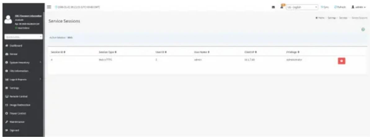
text_image
2004-05-03 96:23:59 8/17-00:80:0MT Service Sessions Action Session - Web Session rib # Session Type # User ID # Olair Name # Cliet IP # Privilege # 4 Web HTTPS 2 admin 16.1.7.48 AdministratorSession Type: Displays the type of the active sessions.
User: Displays the name of the user.
Client IP: Displays the IP addresses that are already configured for the active sessions.
Privilege: Displays the access privilege of the user.
-
Select a slot and click Terminate icon ( ) to terminate the particular session of the service. To modify the existing services:
-
Select a slot and click Edit icon ( ) to modify the configuration of the service.

Note: Whenever the configuration is modified, the service will be restarted automatically. User has to close the existing opened session for the service if needed.
Procedure to modify the existing services:
- Select a slot and click Edit icon () to modify the configuration of the service.

Note: Whenever the configuration is modified, the service will be restarted automatically. has to close the existing opened session for the service if needed.
- This opens the Service Configuration screen as shown in the screenshot below.

text_image
2000-01-01 06:25:51 (UTC+00:00 GMT) Service Configuration Service Name web ✓ Active Interface Name bond0 Non-secure port 80 Secure port 443 Timeout 1800 Maximum Sessions 20 Quick Links.. Dashboard Sensor System Inventory FRU Information Logs & Reports Settings Remote Control Image Redirection Power Control Maintenance Sign out- Service Name is a read only field.
- Activate the Current State by enabling the Active check box.

Note: Interfaces, Non-secure port, Secure port, Time out and Maximum Sessions will not give unless the current state is active.
- Choose any one of the available interfaces from the Interface Name drop-down list.
- Enter the Nonsecure port number in the Non-secure Port field.
- Enter the Secure Port Number in the Secure Port field.
- Enter the timeout value in the Timeout field.
Note: The values in the Maximum Sessions field cannot be modified.

- Click Save to save all changes you have made, else click Cancel to exit.
2-6-12 SMTP Settings
Simple Mail Transfer Protocol (SMTP) is an Internet standard for electronic mail (e-mail) transmission across Internet Protocol (IP) networks.
Using BMC Web GUI, you can configure the SMTP settings of the device.
To open SMTP Settings page, click Settings > SMTP Settings from the menu bar. A sample screenshot of SMTP Settings page is shown below.
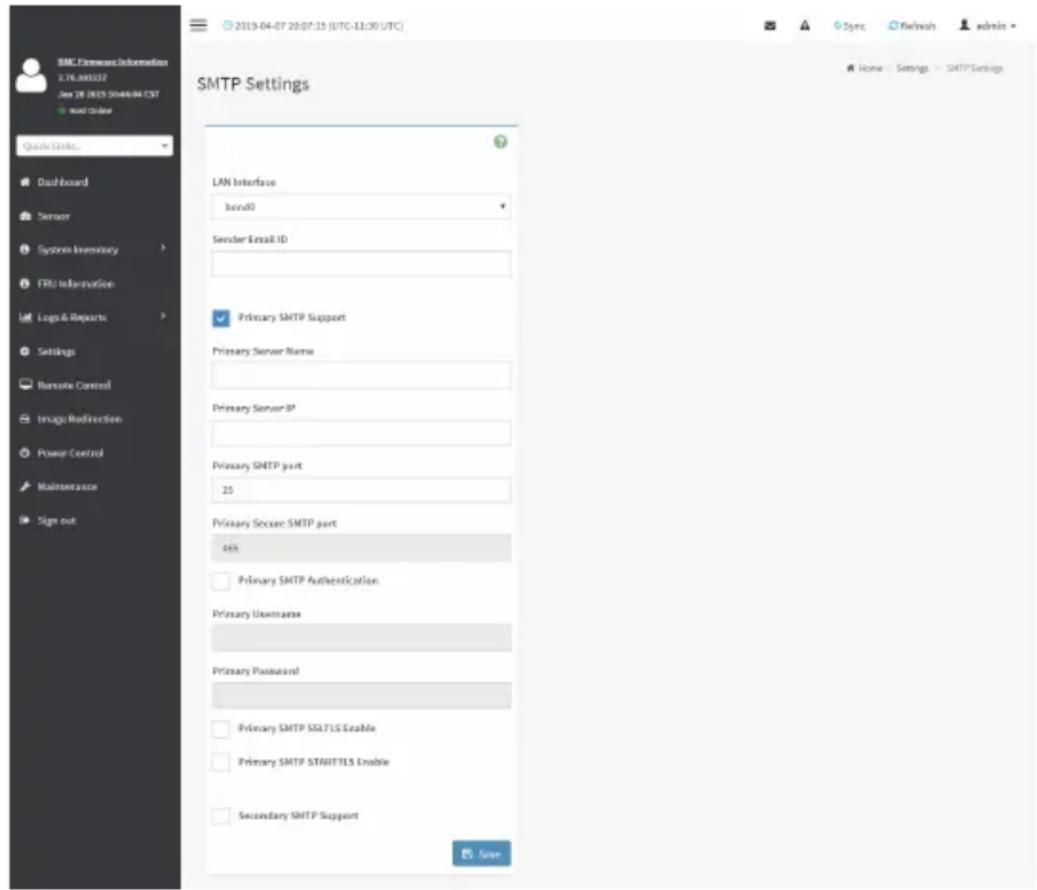
text_image
SMTP Settings LAN Interface bond0 Sender Email ID Primary SMTP Support Primary Server Name Primary Server IP Primary SMTP part 25 Primary Soccer SMTP part 465 Primary SMTP Authentication Primary Username Primary Password Primary SMTP SSLT1S Enable Primary SMTP STARTTLS Enable Secondary SMTP Support SaveThe fields of SMTP Settings page are explained below.
LAN Interface: Displays the list of LAN channels available
Sender Email ID: A valid 'Sender Address' to indicate the BMC, whenever e-mail is sent.
Primary Server Name: The 'Machine Name' of the BMC, from where the e-mail is sent.

Note: Machine Name is a string of maximum 15 alpha-numeric characters.
Space, special characters are not allowed.
Primary SMTP Support: To enable/disable SMTP support for the BMC.
Primary SMTP Port: To specify the SMTP Normal Port.
Primary Secure SMTP Port: To specify the SMTP Secure Port.

Note: For Primary SMTP Port - Default Port is 25, and the Port value ranges from 1 to 65535.
For Primary Secure SMTP Port - Default Port is 465, and the Port value ranges from 1 to 65535.
Primary Server IP: The IP address of the SMTP Server. It is a mandatory field.

Note: IP Address made of 4 numbers separated by dots as in "xxx.xxx.xxx.xxx".
Each Number ranges from 0 to 255.
First Number must not be 0.
Supports IPv4 Address format and IPv6 Address format.
Primary SMTP Authentication: To enable/disable SMTP Authentication.

Note: SMTP Server Authentication Types supported are:
- CRAM-MD5
- LOGIN
- PLAIN
If the SMTP server does not support any one of the above authentication types, the user will get an error message stating "Authentication type is not supported by SMTP Server."
Primary Username: Enter username to access SMTP Accounts.

Note: User Name can be of length 4 to 64 alpha-numeric characters, dot(.), dash(-), and underline(_) .
It must start with an alphabet.
Other Special Characters are not allowed.
Primary Password: Enter password for the SMTP User Account.

Note: Password must be at least 4 characters long.
Blank space is not allowed.
This field will not allow more than 64 characters.
Primary SMTP STARTTLS Enable: To enable STARTTLS support for the SMTP Client.
- Upload SMTP CA Certificate File: File that contains the certificate of the trusted CA certs. CACERT key file should be of pem type,LOGIN
- Upload SMTP Certificate File: Client certificate filename. CERT key file should be of pem type.
- Upload SMTP Private Key: Client private key filename. SMTP key file should be of pem type.

Note: To enable STARTTLS support, the respective SMTP support option should be enabled.
Secondary SMTP Support: It lists the Secondary SMTP Server configuration. It is an optional field. If the Primary SMTP server is not working fine, then it uses Secondary SMTP Server configuration.

Note: Options of Secondary SMTP Support are same as Primary SMTP Support.
Save: To save the new SMTP server configuration.
Procedure
- Select the LAN Interface from the drop-down list.
- Enter the Sender Email ID in the specified field.
- Check Primary SMTP Support option to enable SMTP support for the BMC.
- Enter the Machine Name of the SMTP Server in the Primary Server Name.

Note: - Machine Name is a string of maximum 15 alpha-numeric characters.
Space, special characters are not allowed.
- Enter IP address of the SMTP Server in the Primary Server IP field. It is a mandatory field.
- Enter the Primary SMTP Port in the specified field.
- Enter the Primary Secure SMTP Port in the specified field.
- Enable the check box Primary SMTP Authentication if you want to authenticate SMTP Server.
- Enter your Primary User name and Primary Password in the respective fields.
- Enable the check box Primary SMTP SSLTLS Enable to send data through secure Port.

Note: If this option is selected, STARTTLS option and Normal Port will be hidden.
- Check the Secondary SMTP Support option to enable Secondary SMTP support for the BMC.
- Enter the Secondary Server Name, Secondary Server IP, Secondary SMTP Port and Secure Port values in the respective fields.
- Enable the check box SMTP Server Authentication if you want to authenticate SMTP Server.
- Enter your Secondary User name and Password in the respective fields.
- Enable the check box Secondary SMTP SSLTLS to send data through secure Port.

Note: If this option is selected, STARTTLS option and Normal Port will be hidden.
- Click Save to save the entered details.
2-6-13 SSL Settings
The Secure Socket Layer protocol was created by Netscape to ensure secure transactions between web servers and browsers. The protocol uses a third party, a Certificate Authority (CA), to identify one end or both end of the transactions.
Using BMC Web GUI, configure SSL certificate into the BMC. Using this, the device can be accessed in a secured mode.
To open the SSL Certificate Configuration page, click Settings > SSL Settings from the menu bar. There are three tabs in this page.
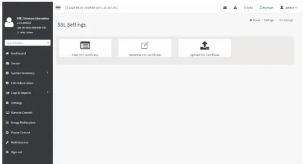
text_image
BMC Firmware Information 2.76.000227 View 28 2019 304nd/04 CST Wind Chrome Quick Links... Dashboard Sensor System Inventory FRU Information Logs & Reports Settings Remote Control Image Redirection Power Control Maintenance Sign out 2013-04-07 20:59:55 (UTC-11:30 UTC) Sync Refresh admin SSL Settings None - Settings - SSL Settings View 551 certificate Generate 551 certificate Upload 551 certificate- Upload SSL Certificate option is used to upload the certificate and private key file into the BMC.
- Generate SSL Certificate option is used to generate the SSL certificate based on configuration details.
• View SSL Certificate option is used to view the uploaded SSL certificate in readable format.
A sample screenshot of Upload SSL Certificate page is shown below.
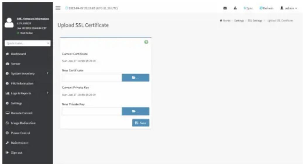
text_image
BMC Licensee Information 2.76.390327 Jan 28 2019 10/4/2019 CST Next Update Quick Links... Dashboard Sensor System Inventory FBU Information Logo & Reports Settings Remote Control Image Modifunction Power Control Maintenance Sign out 2019-04-07 20:10:05 (UTC-11:30 UTC) Upload SSL Certificate Current Certificate Sun Jan 27 14:30:28 2019 New Certificate Current Private Key Sun Jan 27 14:30:28 2019 New Private Key SaveThe fields of SSL Settings - Upload SSL Settings tab are explained below.
Current Certificate: Current certificate and uploaded date/time will be displayed (read-only).
New Certificate: Certificate file should be of pem type
Current Private Key: Current Private key information will be displayed (read-only).
New Private Key: Private key file should be of pem type
Upload: To upload the SSL certificate and privacy key into the BMC.

Note: After successful upload, HTTPS service will restart to use the newly uploaded SSL tificate.
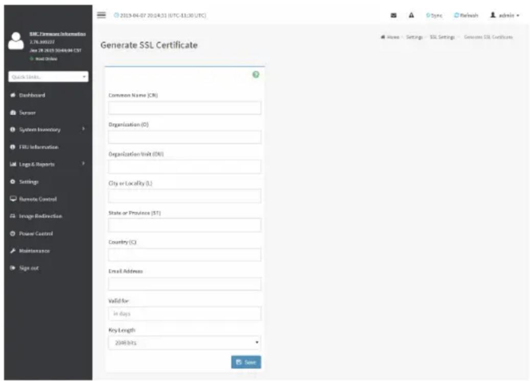
text_image
BMC Software Information 2.78.300227 Jan 28 2013 10:48:04 CST most size Quick links... Dashboard Sensor System Inventory FRU Information Log& Reports Settings Remote Control Image Redirection Power Control Maintenance Sign out Generate SSL Certificate Common Name (CN) Organization (O) Organization Unit (OU) City or Locality (L) State or Province (ST) Country (C) Email Address Valid for: in days Key Length: 2008 bits SaveThe fields of SSL Settings - Generate SSL Certificate are explained below.
Common Name(CN): Common name for which certificate is to be generated.
• Maximum length of 64 characters.
• It is a string of alpha-numeric characters.
- Special characters ‘#’ and ‘\$’ are not allowed.
Organization(O): Organization name for which the certificate is to be generated.
• Maximum length of 64 characters.
• It is a string of alpha-numeric characters.
- Special characters ‘#’ and ‘\$’ are not allowed.
Organization Unit(OU): Over all organization section unit name for which certificate is to be generated.
• Maximum length of 64 characters.
• It is a string of alpha-numeric characters.
- Special characters ‘#’ and ‘\$’ are not allowed.
City or Locality(L): City or Locality of the organization (mandatory).
• Maximum length of 128 characters.
• It is a string of alpha-numeric characters.
- Special characters ‘#’ and ‘\$’ are not allowed.
State or Province(ST): State or Province of the organization (mandatory).
• Maximum length of 64 characters.
- It is a string of alpha-numeric characters.
• Special characters '#' and '\$' are not allowed.
Country(C): Country code of the organization (mandatory).
• Only two characters are allowed.
• Special characters are not allowed.
Email Address: E-mail Address of the organization (mandatory).
Valid for: Validity of the certificate.
• Value ranges from 1 to 3650 days.
Key Length: The key length bit value of the certificate.
Save: To generate the new SSL certificate.

Note: HTTPS service will get restarted, to use the newly generated SSL certificate.
The fields of SSL Settings - View SSL Certificate are explained below.

text_image
2000-01-01 06:40:07 (UTC+00:00 GMT) View SSL Certificate Current Certificate Information Certificate Version 3 Serial Number EF1CFC77T4T3FD08 Signature Algorithm sha25BWithRSAEncryption Public Key (2048 bit) Issuer Common Name (CN) megarac.com Issuer Organization (O) American Megatrends International LLC (AMI) Issuer Organization Unit (OU) Service Processors Issuer City or Locality (L) Norcross Issuer State or Province (ST) Georgia Issuer Country (C) US Issuer Email Address support@amiu.com Valid From Aug 27 13:03:00 2019 GMT Valid TIRBasic Information: This section displays the basic information about the uploaded SSL certificate. It displays the following fields:
- Version Serial Number
• Signature Algorithm - Public Key
- Issuer Common Name(CN)
- Issuer Organization(O)
• Issuer Organization Unit(OU) - Issuer City or Locality(L)
• Issuer State or Province(ST) - Issuer Country(C)
- Issuer E-mail Address
- Valid From
- Valid Till
Procedure
- Click the Upload SSL Certificate tab, Browse the New Certificate and New Private key.
- Click Upload to upload the new certificate and private key.
-
In Generate SSL Certificate, enter the following details in the respective fields:
-
The Common Name for which the certificate is to be generated.
-
The Organization for which the certificate is to be generated.
• The Organization Unit name for which certificate to be generated.
• The City or Locality of the organization
• The State or Province of the organization
• The Country of the organization
• The Email address of the organization.
• The number of days the certificate will be valid in the Valid For field. -
Choose the Key Length bit value of the certificate
- Click Save to generate the certificate.
- Click View SSL Certificate tab to view the uploaded SSL certificate in user readable format.

Note: Once you Upload/Generate the certificates, only HTTPS service will get restarted.
a can now access your Web securely using the following format in your IP Address
field from your Internet browser: https://
For example, if your BMC's IP address is 192.168.0.30, enter the following:
https://192.168.030
Please note the after
2-6-14 System Firewall
In MegaRAC GUI, the System Firewall page allows you to configure the firewall settings. The firewall rule can be set for an IP or range of IP Addresses or Port numbers. To view this page, you must at least be an operator. Only administrators can add or delete a firewall.
To open System Firewall page, click Settings > System Firewall from the menu bar.
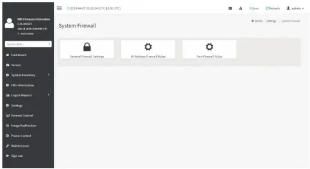
text_image
BMC Firearm Information 2.76.39027 Jan 28 2019 10:44:04 CST Build Order Quick Links... Dashboard Sensor System Inventory FRU Information Logo & Reports Settings Remote Control Image Redirection Power Control Maintenance Sign out 2019-04-07 20:19:34 (UTC-11:30 UTC) Sync Refresh admin Home Settings System Firewall General Firewall Settings IP Address Firewall Rules Port Firewall RulesGeneral Firewall Settings
Click General Firewall Settings page. A sample screenshot of General Firewall Settings page is shown below.

text_image
BMC Firewall Information 2.76.300327 Jan 28 2019 10:44:04 CST Wind Drive Quick Links... Dashboard Sensor System Inventory FRU Information Logs & Reports Settings Remote Control Image Redirection Power Control Maintenance Sign out 2019-04-07 20:20:45 (UTC-11:30 UTC) General Firewall Settings Existing Firewall Settings Add Firewall SettingsTo View Existing Firewall Settings
Click General Firewall Settings > Existing Firewall Settings icon. A blank page will be opened if you did not add anything in "Add Firewall Settings". If any settings are added, then the added rule will be listed in "Existing Firewall Settings" page. A sample screenshot of Existing Firewall Settings page is shown below.
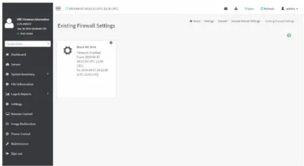
text_image
BMC Transmission Information L7F.390207 Date: 28/2019 10:46:04 CST Next Update Quick Links. Dashboard Sensor System Inventory FRU Information Logo & Reports Settings Remote Control Image Redirection Power Control Maintenance Sign out 2019-04-07 20:23:12 (UTC-11:30 UTC) Existing Firewall Settings Black Alt: IP# Timeout: Enabled From 2019-04-07 29:22:00 (UTC 11:30) UTC For: 2019-04-07 23:22:00 (UTC 13:10 UTC) Home Settings Firewall General Firewall Settings Existing Firewall SettingsThe Existing Firewall Settings page allows you to remove any particular Existing Firewall Settings.
Procedures
- Click General Firewall Settings > Existing Firewall Settings icon. A sample screenshot of Existing Firewall Settings page is shown below.
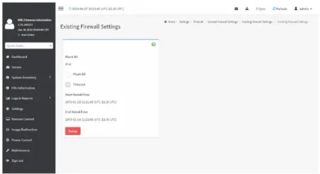
text_image
BMC Firewall Information 2.78.390257 Jan 28 2019 10:44:09:41 CST + Quick Order Quick Queue... Dashboard Sensor System Inventory FRU Information Logic & Reports Settings Remote Control Image Redemption Power Control Maintenance Sign out Existing Firewall Settings Black All IP6 Flush All Timeout Start Date&Time 1970-01-18 12:21:49 (UTC-11:30 UTC) End Date&Time 1970-01-18 12:22:66 (UTC-11:30 UTC) Delete- Block All: The blocked incoming IP's and Port's can be viewed.
- Flush All: To flush all the system firewall rules (Read-Only).
- Select Timeout to enable or disable firewall rules with timeout.
- Time Out : The respective firewall rule effect Start Time, End Date, Start Time, End Time will be displayed.
- Delete: To Delete the system firewall rules.
Add Firewall Settings
Click General Firewall Settings > Add Firewall Settings. This opens the Add Firewall Settings page as shown below.
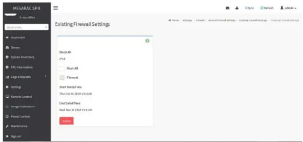
text_image
MEGARAC SPX @ next offices Quick Links... Existing Firewall Settings Block All IPv6 Flush All Timeout Start Date&Time Thu Dec 01 2018 13:11:09 End Date&Time: Wed Dec 21 2018 13:11:09 Delete- Select Block All to block all the incoming IP's and Port's.
- Select Flush All to flush all the system firewall rules.
- Select Timeout to enable or disable firewall rules with timeout.
- Enter Start Time to start the respective firewall rule effect from this time.
- Enter End Time to end the respective firewall rule effect from this time.

Note: The time should be in the dd-mm-yy:hh-mm format.
- Click Save to save the changes made else click Cancel to go back to the previous screen.
IP Address Firewall Rules
Click IP Firewall Rules page. A sample screenshot of IP Firewall Rules page is shown below.
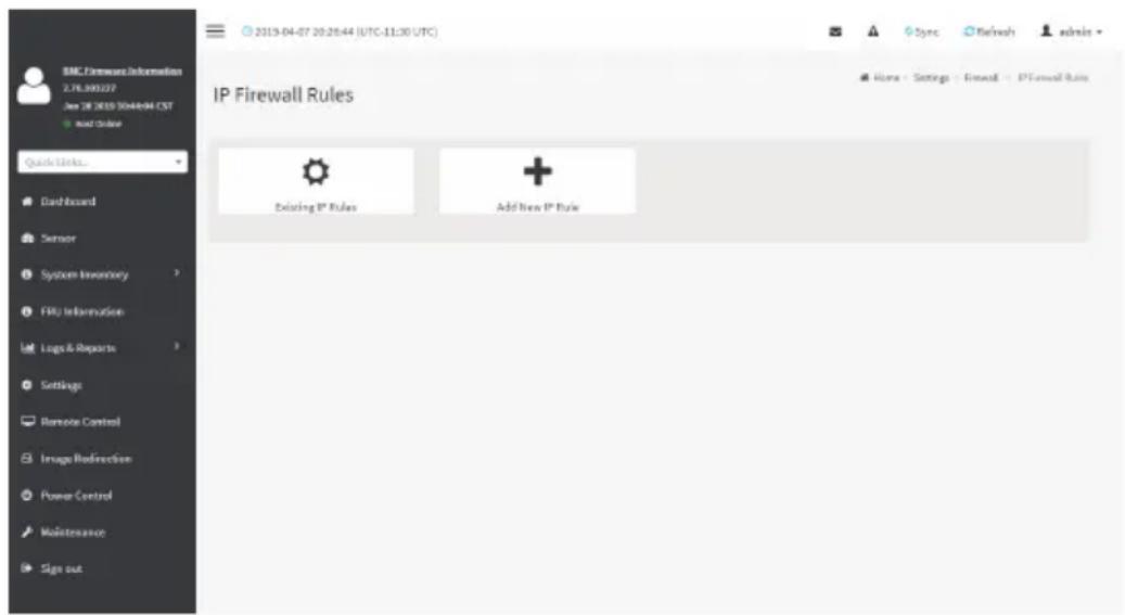
text_image
BMC Features Information 2.76.30022? See QR 2019 10448441.CST Word Style Quick Links... Dashboard Sensor System Inventory FRU Information Logo & Reports Settings Remote Control Image Redirection Power Control Maintenance Sign out 2019-04-07 20:20:44 (UTC-11:30 UTC) IP Firewall Rules Existing IP Rules Add New IP Rule Sync Refresh admin Home - Settings - Firewall - IP Firewall RulesThe fields of IP Address Firewall tab are explained below.
To View Existing IP Rules or a range of IP Addresses
Click Settings > System Firewall > IP Address Firewall Rules > Existing IP Rules. A blank page will be opened if you did not add anything in "Add IP Rule". If any rule is added, then the added rule will be listed in "Existing IP Rules" page.
A sample screenshot of Existing IP Rules page is shown below.

text_image
BMC Features Information 2.76.300227 Jan 28 2019 10/4/2019 GMT + mail code Quick Links... Dashboard Server System Inventory FBU Information Logo & Reports Settings Remote Control Image Redirection Power Control Maintenance Sign out 2019-04-07 20:27:52 (UTC-11:30 UTC) Existing IP Rules IP / IP Range: 10.1.1.112.123 - 10.1.1.112.127 Rule 4Flow Firmware Enabled From 2019-04-07 29:27:49 (UTC-11:30) UTC Fax: 2019-04-10 23:27:48 (UTC-11:30 UTC) Home - Settings - Firewall - IP Oriented Firewall Rule - Existing IP RuleThe Existing IP Rules page allows you to remove any particular Existing IP Rules.
Procedures
- Select the Existing IP Rules you want to remove.
- Click on Delete to remove the selected Existing IP Rules.

text_image
SNC Framework Information L.TN.300127 Jan 28 2019 10:44:04 EST Start Update Quick Status... Dashboard Service System Inventory File Information Logo & Reports Settings Remote Control Image Refreshline Power Control Maintenance Sign out Existing IP Rules IF Single (or) Range Start 10.1.111.127 IF Range End 10.1.111.127 Enable Timeout Start Date&Time 2019-04-07 20:27:00 (UTC-11:30 UTC) End Date&Time 2019-04-10 22:27:00 (UTC-11:30 UTC) Rule Allow DeleteIP Single (or) Range Start - To show the configured Port Address or Range of Ports.
IP Range End - To show the configured Port Address or Range of Ports.
Enable Timeout - To enable/disable Timeout.
Start Date - The respective firewall rule effect will start from this date.
Start Time - The respective firewall rule effect will start from this time.
End Date - The respective firewall rule effect will end from this date.
End Time - The respective firewall rule effect will end from this time.
Rule - To indicate the current setting of the listed Port or Range of Port rules (Allow or Block) status.
Delete - To delete the selected slot.
Procedures
- Click Settings > System Firewall > IP Address Firewall Rules > Add New IP Rule to add a new IP or range of IP address.

text_image
Add IP Rule IP Single (or) Range Start IP Range End optional Enable Timeout Start Date 2019-04-07 Start Time 20:30 End Date 2019-04-07 End Time 20:30 Rule Save- In the Add new rule for IP page, Enter the IP address and a range of IP addresses in the IP Single or IP Range Start field.

Note: IP Address will support IPv4 Address format only:
TPv4 Address made of 4 numbers separated by dots as in xxx.xxx.xxx.xxx.
Each number ranges from 0 to 255.
First number must not be 0.
IPv6 Address made of 8 groups of 4 Hexadecimal digits separated by colon as in xxxx:xxxx:xxxx:xxxx:xxxx:xxxx:xxxx:xxxx.
- Enter IP range end value in the IP Range End field.
- Enable Timeout to enable firewall rules with timeout.
- Enter Start Date to start the respective firewall rule effect from this date.
- Enter End Date to end the respective firewall rule effect from this date.
- Enter Start Time to start the respective firewall rule effect from this time.
- Enter End Time to end the respective firewall rule effect from this time.

Note: The date and time should be in the YYYY/MM/DD and hh-mm format respectively.
- Determine the rule to block or accept.
- Click Save to save the changes made.
Port Firewall Rules
Click Port Firewall Rules page. A sample screenshot of Port Firewall Rules page is shown below.
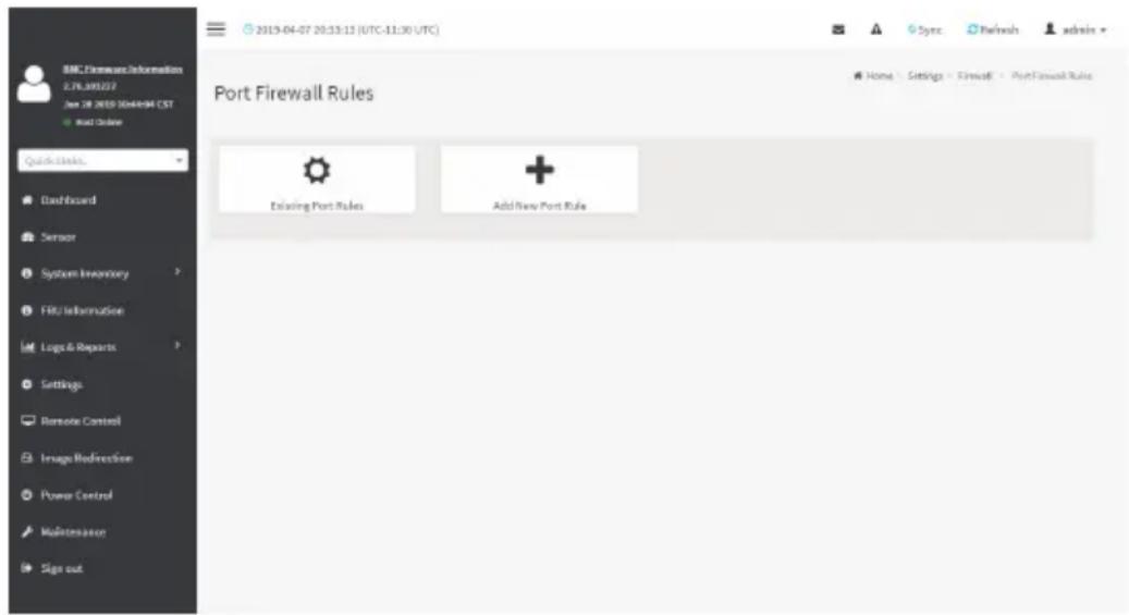
text_image
BMC Firewall Information 2.76.390227 Jan 28 2013 10:44:04 GMT Add Order Quick Links. Dashboard Sensor System Inventory FBU Information Logic & Reports Settings Remote Control Image Redirection Power Control Maintenance Sign out 2013-04-07 20:53:13 (UTC-11:30 UTC) Port Firewall Rules Existing Port Rules Add New Port Rule Sync Refresh admin Home Settings Firewall Port Firewall RulesThe fields of Port Firewall Rules tab are explained below.
To view Existing Port Rules
Click Settings > System Firewall > Port Firewall Rules > Existing Port Rules. A blank page will be opened if you did not add anything in "Add New port Rule". If any rule is added, then the added rule will be listed in "Existing Port Rules" page.
A sample screenshot of Existing Port Rules is shown below.
The Existing Port Rules page allows you to remove any particular Existing Port Rules.

text_image
BMC Firmware Information 2.76.300127 Jan 28 2019 Notepad CST Mail Course Quick Links... Dashboard Sensor System Inventory FRU Information Logo & Reports Settings Remote Control Image Redirection Power Control Maintenance Sign out 2019-04-07 20:54:42 (UTC-11:30 UTC) Existing Port Rules Port / Port Ranger 123 - IPv6 Protocol TCP Network Type: IPv4 Allow Timeout: EvalMod From 2019-04-07 20:33:00 (UTC 11:00 UTC) Fax: 2019-04-26 21:33:00 (UTC 11:30 UTC)Procedures
- Select the Existing Port Rules you want to remove.
- Click on Delete to remove the selected Existing Port Rules.

text_image
BMC Transmission Information 2.76.300227 Jan 28 2013 10:44:04 CST Quick Links... Dashboard Sensor System Inventory FRU Information Logo & Reports Settings Remote Control Imago Radirection Power Control Maintenance Sign out 2013-04-07 20:35:06 (UTC-11:30 UTC) Existing Port Rules Port Single (or) Range Start 123 Port Range End 458 Protocol TCP Network Type IPyA Enable Timeout Start Date&Time 2013-04-07 20:33:00 (UTC-11:30 UTC) End Date&Time 2013-04-25 21:33:00 (UTC-11:30 UTC) Rule Allow DeleteThe fields of System Firewall - Existing Port Rules page are explained below.
Port Single (or) Range Start - To configure the Port or Range of Port Addresses.
Port Range End - To configure the Port or Range of Port Addresses.
Protocol - This field specifies the protocols for the configured Port or Port Ranges.
Network Type - This field specifies the affected network type for the particular Port or Port Ranges.
Enable Timeout - To enable or disable firewall rules with timeout.
Start Date - The respective firewall rule effect will start from this time.
Start Time - The respective firewall rule will start from this time.
End Date - The respective firewall rule effect will end on this date.
End Time - The respective firewall rule will end at this time.
Rule - To indicate Allow or Block status.
Delete - To delete the entry to the firewall rules list.
Procedure to add Port/Range of ports
- To add a new range of Port address, click the Add button
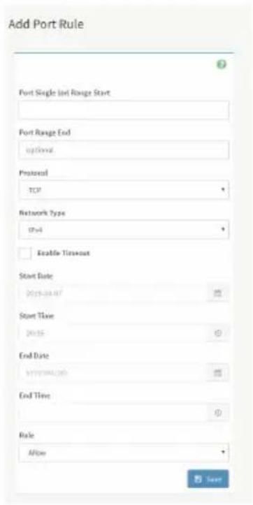
text_image
Add Port Rule Port Single Start Range Start Port Range End optional Protocol TCP Network Type Start Enable Timeout Start Date 2015-04-07 Start Time 2015 End Date 2015-04-07 End Time Rule Allow Save- In the Add new rule for Port window, enter the port number or a range of port numbers in the Port Single (or) Range Start field.
- Enter the end value in the Port Range End field.
- Select the Protocol to be either TCP or UDP or Bot.
- Select the Network Type. It may be IPv4 or IPv6 or Both.
- Select Timeout to enable or disable firewall rules with timeout.
- Enter Start Time to start the respective firewall rule effect from this time.
- Enter Start Date to start the respective firewall rule effect from this date.
- Enter End Date to end the respective firewall rule effect on this date.
- Enter End Time to end the respective firewall rule effect at this time.
Note: The time should be in the YYYY/MM/DD:hh-mm format.

- Select the Rule to determine the rule to Block or Allow.
- Click Save to save the changes made.
2-6-15 User Management
In BMC Web GUI, the User Management page allows you to view the current list of user slots for the server. You can add a new user and modify or delete the existing users.
To open User Management page, click Settings > User Management from the menu bar. A sample screenshot of User Management page is shown below.

text_image
SNC Framework Information JL70.88227 User 28 2019 10:44:04:15 EST Quick Clicks Dashboard Sensor System Inventory FRU Information Logo & Reports Settings Remote Control Image Redirection Power Control Maintenance area Sign out 2019-04-07 20:42:25 (UTC-11:30 UTC) User Management Channel 1 Channel 1 1 Langerous (Disabled) Administrator KIME (Disabled) Channel 1 2 admin (Active) Administrator KIME (Disabled) Channel 1 3 ADMIN (Active) Administrator KIME (Disabled) Channel 1 4 (Disabled) Channel 1 5 (Disabled) Channel 1 6 (Disabled) Channel 1 7 (Disabled) Channel 1 8 (Disabled) Channel 1 9 (Disabled) Channel 1 10 (Disabled) Channel 1 11 (Disabled) Channel 1 12 (Disabled) Channel 1 13 (Disabled) Channel 1 14 (Disabled) Channel 1 15 (Disabled) Channel 1 16 (Disabled)Click user icon ( ) and select any free slot to add a new user from the User Management main page.

Note: The Free slots are shown as "Disabled" in all columns for the slot. The fields of User Management page are explained below.
User ID: Displays the ID number of the user.

Note: The list contains a maximum often users only.
User Name: Displays the name of the user.
User Access: To enable or disable the access privilege of the user.
Network Privilege: Displays the network access privilege of the user.
SNMP Status: Displays if the SNMP status for the user is enabled or Disabled.
E-mail ID: Displays e-mail address of the user.
Add User: To add a new user.
Delete User: To delete an existing user.
Procedure to add a new User
- To add a new user, select a free section and click on the empty section. This opens the Add User screen as shown in the screenshot below.
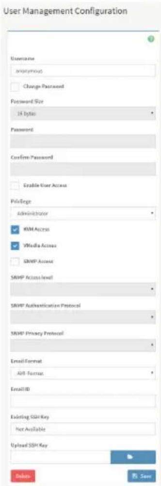
text_image
User Management Configuration Username anonymous Change Password Password Size 16 bytes Password Confirm Password Enable User Access Privilege Administrator KVM Access VMedia Access SNMP Access SNMP Access level SNMP Authentication Protocol SNMP Privacy Protocol Email Format AH-Formus Email ID Existing SSH Key Not Available Uploaded SSH Key Browse Save- Enter the name of the user in the User Name field.

Note: User Name is a string of 1 to 16 alpha-numeric characters.
It must start with an alphabetical character.
It is case-sensitive.
Special characters '-'(hyphen), '-' (underscore), '@'(at sign) are allowed.
For 20 Bytes password, LAN session will not be established.
- Set Password Size for the new password.
- In the Password and Confirm Password fields, enter and confirm your new password.

Note: Password should be the combination of alphabets, numbers, symbol and upper characters.
Blank space is not allowed.
This field will not allow more than 16/20 characters based on Password size field value.
This field will not allow the below mentioned characters.
The password should be a string, if you try to set password using "ipmitool user set password".
| Hex Char | |
| 00 NUL '\0' | |
| 01 SOH (start of heading) | |
| 02 STX (start of text) | |
| 03 ETX (end of text) | |
| 04 EOT (end of transmission.) | |
| 05 ENQ (enquiry) | |
| 06 ACK (acknowledge) | |
| 07 BEL '\a' (bell) | |
| 08 BS '\b' (backspace) | |
| 09 HT '\t' (horizontal lab) | |
| 0A LF '\n' (new Line) | |
| 0B VT '\v' (vertical tab) | |
| 0C FF '\f' (form feed) | |
| 0D CR '\r' (carriage ret) | |
| 0E SO (shift out) | |
| 0F SI (shift in) | |
| 10 DLE (data link escape) | |
| 11 DC1 (device control 1 ) | |
| 12 IDC2 (device control 2) | |
| 13 DG3 (device control 3) | |
| 14 DC4 (device control 4) | |
| 15 NAK (negative ack.) | |
| 16 SYN (synchronous idle) | |
| 17 ETB (end of trans. blk) | |
| 18 CAN (cancel) | |
| 19 EM (end of medium) | |
| 19 EM (end of medium) | |
| 1A SUB (substitute) | |
| 1B ESC (escape) | |
| 1C FS (file separator) | |
| 1D GS (group separator) | |
| 1E RS (record separator) | |
| 1F US (unit separator) | |
| 20 SPACE | |
| 7F DEL |
- Enable or Disable the Enable User Access Privilege.

Note: Enabling User Access will intern assign the IPMI messaging privilege to user.
It is recommended that the IPMI messaging option should be enabled for the user to enable the User Access option, while creating User through IPMI.
- In the Network Privilege and Serial Previlege fields, select the privileges assigned to the user which could be Administrator, Operator, User, OEM or None.
- Check KVM Access to assign the KVM privilege for the user.
- Check VMedia Access assign the VMedia privilege for the user.

Note: It is recommended that the privileges support to KVM and VMedia should be ided only to the ADMIN user and shouldn't be provided to USER and OPERATOR ege level users. The Admin user can provide the privilege support to USER and RATOR privilege level users at their own risk.
VMedia Privilege only restricts initiating / starting media redirection. If a device is already being redirected and attached to the host, then in host it will be visible as normal device. Hence, it will be accessible to all the KVM sessions, which includes 'KVM Privilege only' sessions as well.
- Check the SNMP Access check box to enable SNMP access for the user.

Note: Password field is mandatory, if SNMP Status is enabled.
- Choose the SNMP Access level option for user from the SNMP Access level (SHA or MD5) drop-down list. Either it can be Read Only or Read Write.
- Choose the SNMP Authentication Protocol (SHA or MD5) to use for SNMP settings from the drop down list.

Note: Password field is mandatory, if Authentication protocol is changed.
- Choose the Encryption algorithm to use for SNMP settings from the SNMP Privacy protocol (AES or DES) drop-down list.
- In the Email ID field, enter the email ID of the user. If the user forgets the password, the new password will be mailed to the configured email address.

Note: SMTP Server must be configured to send emails.
Email Format: Two types of formats are available:
- AMI-Format: The subject of this mail format is 'Alert from (your Host name)'. The mail content shows sensor information, ex: Sensor type and Description.
-
Fixed-Subject Format: This format displays the message according to user's setting. You must set the subject and message for email alert.
-
In the Upload SSH Key field, click Browse and select the SSH key file.

Note: SSH key file should be of pub type.
- Click Save to save the new user and return to the users list.
To Modify User
- To modify the existing user, click on the active user tab. This opens a User screen as shown in the screenshot below.

text_image
User Management Configuration Username anonymous Change Password Password Size 14 bytes Password Confirm Password Enable User Access Package Administrator KSM Access VMedia Access SMTP Access SMTP Access level SMTP Authentication Protocol SMTP Privacy Protocol Email Format API-Format Email ID Existing SSH Key Not Available Upload SSH Key Delete Save- Check Change Password, if you wish to change the existing Password.
- Follow the steps (3 to 15) of Procedure to add a new User.
- Click Save to save the changes and return to the users list.
- Click Delete to delete the user.
2-6-16 Video Recording
The Video Recording consists of the following:
- Auto Video Settings
• Video Trigger Settings
• Video Remote Storage
• Pre-Event Video Recordings
-
SOL Settings
-
SOL Trigger Settings
• SOL Video Remote Storage -
SOL Recorded Video
-
JAVA SOL
A sample screenshot of the Video Recording is given below.
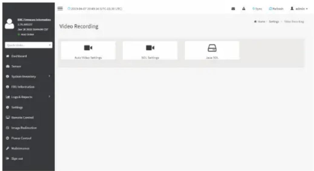
text_image
BMC Features Information 2.76.300227 Jan 28 2019 10/4-04 CST Auto Video Quick Links... Dashboard Sensor System Inventory FRU Information Logs & Reports Settings Remote Control Image Redirection Power Control Maintenance Sign out 2019-04-07 20:43:14 (UTC-11:30 UTC) Video Recording Auto Video Settings SQL Settings Java SQLA detailed description of the menu items are given below.
Auto Video Settings
The Auto Video Settings page allows you to configure the events that will trigger auto video recording function of the KVM server and view the current list of user slots for the server. You can add a new user and modify or delete the existing users.
This page is used to configure the events that will trigger auto video recording function of the KVM server.

text_image
2019-04-07 20:56:18 (UTC-11:30 UTC) Auto Video Settings Video Trigger Settings Video Remote Storage Fox-Event Video RecordingsTo triggers for Auto Video Recording, click Video Recording > Auto Video Settings > Video Trigger Settings from the menu bar. A sample screenshot of Video Trigger Settings page is shown below.
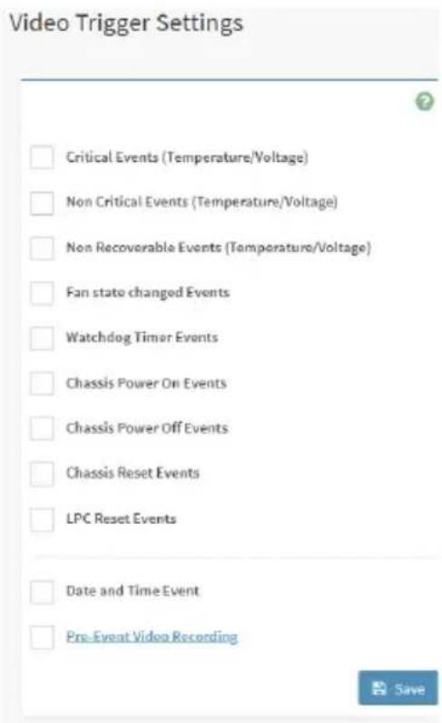
text_image
Video Trigger Settings Critical Events (Temperature/Voltage) Non Critical Events (Temperature/Voltage) Non Recoverable Events (Temperature/Voltage) Fan state changed Events Watchdog Timer Events Chassis Power On Events Chassis Power Off Events Chassis Reset Events LPC Reset Events Date and Time Event Pre-Event Video RecordingVideo Trigger Settings
Event List: It shows the list of available events to be configured. The events are mentioned below.
• Critical Events (Temperature/Voltage)
• Non Critical Events (Temperature/Voltage)
• Non Recoverable Events (Temperature/Voltage)
• Fan state changed Events
- Watchdog Timer Events
- Chassis Power on Events
- Chassis Power off Events
- Chassis Reset Events
- LPC Reset Events
- Date and Time Event
• Pre-Event Video Recording - Pre-crash
- Pre-reset
Save: To save the current changes.
Procedure
- Check the events to be enabled.
- To set particular Date and Time Event, check the option Date and Time Event.
a) Choose the month, day and year from the Date field
b) Enter/Choose the Time in hh:mm format in the respective fields.

Note: KVM service should be enabled to perform auto-video recording. The date and should be in advance to the system date and time.
- Click Pre-Event Video Recording to edit the Pre-Event video recording configurations. A sample screenshot of Pre-Event Video Recordings page is shown as below.

text_image
BMC Fireworks Information 2.7L 300227 Jan 28 2010 1044694 CST Quick Links... Dashboard Sensor System Inventory FRU Information Log & Reports Settings Remote Control Image Redirection Power Control Maintenance Sign out 2013-04-07 21:02:02 (UTC-11:30 UTC) Pre-Event Video Recordings This page is used to configure the Pre-Event video recording options. Pre-Event video recording is disabled by default. To enable the Pre-Event video recording, go to the Trigger Configuration page. Video Quality Very Low Compression Mode High Frames Per Second 1 Video Duration 10 Savea) To set video quality, select ranges (very low, low, high, average and normal) from Video Quality drop-down list.
b) To set compression mode, select modes (high, normal, low, no) from Compression Mode drop-down list.
c) To set number of frames per second, select frames/sec (1-4) from Frames Per
Second drop-down list.
d) To set duration of video, select second (10-60) from Video Duration drop-down list.
e) Click Save to save the changes made on the Pre-Event Video Recording.
-
Select Crash Reset either Pre-crash or Pre-reset.
-
- Click Save to save the changes.
Video Remote Storage
To Video Remote Storage capture host video before critical event like crash or reset occurs, click Video Recording > Auto Video Settings > Video Remote Storage.
A Sample screenshot of Video Remote Storage is as shown below.

text_image
2015-04-07 21:04:30 (UTC-11:30) UTC Quick Links... Dashboard Sensor System Inventory FRU Information Logo & Reports Settings Remote Control Image Radirection Power Control Maintenance Sign out Record Video to Remote Server Maximum Durings 1 Maximum Duration (Sec) 10 Maximum Size (MIS) 5 Server Address Server IP or Host Name Path in server up /upt/bre/videos Share Type: MFS CFPS Save- Check Record Video to Remote Server to enable the Remote Video Support.

Note: By default, video files will be stored in local path of BMC. If remote video support enabled, then the video files will be stored only in remote path, not within BMC.
- Enter Maximum Duration (Sec) of the video.
- Enter Maximum Size (MB) of the video.
- Enter Maximum Dumps of the video.

Note: The Maximum Duration of the video should be in the range from 1 to 3600 ends. The Maximum Size of the video should be in the range from 1 to 500 mb.
The Maximum Dumps should be in the range from 1 to 100. The recorded video file should meet either the size constraint or duration constraint, according to the configured settings, depending on which constraint is met first.
- Enter the Server Address.

Note: Server address will support the following: address (Both IPv4 and IPv6 format).
FQDN (Fully qualified domain name) format.
- Enter the source path in Path in Server field
- Select the Share Type (NFS/CIFS). If the selected share type is (CIFS), enter the User Name, Password and Domain Name in the respective fields.
- Click Save to save the settings.
Pre-Event
Pre-Event video recording files will be named as per event captured. For example - if any video is recorded for Crash Event, the recorded file will be named as pre_crash_video_x.dat, where x is file count, similarly if it is recorded for reset event it will be named as pre_reset_video_x.dat.
Post-Event
Post-Event video recording files will be named as shown below.
video_dump_
File Count and Duration for Pre and Post Event Recordings are as shown in the below table:
| Auto Video Recording (Post Event) | Pre-Event Video Recording(only for Crash/reset event) | |
| Time Limits 20 seconds or 5.5 | MB video allowed if Local Storage. | Default-10sec, but can be configurable up to 60sec. |
| 300 seconds recording allowed if Remote Storage (Remote Path). | ||
| Video File Count Local Storage: 2 | After 2, if video recording starts, the oldest video file among the two files will be replaced with the new video) | 1 if local storage/3 if remote storage. (Once Max file count reached, will Delete Old video file to store new file.) |
| Remote Storage: maximum configured dump value of video files for Remote Storage. |
SOL Settings
To open SOL Set page, click Settings > Video Recording > SOL Settings from the menu bar. A sample screenshot of SOL Settings page is shown below.

text_image
BMC Licensee Information 2.76.3903/27 Jun 28 2019 Outlook GST Mail Course Quick Links... Dashboard Sensor System Inventory FRU Information Logo & Reports Settings Remote Control Image Redirection Power Control Maintenance Sign out 2019-04-07 21:07:53 (UTC-11:30 UTC) Sol Settings SOL Trigger Settings SOL Remote Storage SOL Recorded Files Home - Settings - video - Sol SettingsThe SOL Settings consists of three fields:
- SOL Trigger Settings
• SOL Video Remote Storage - SOL Recorded Video
SOL Trigger Settings
Event List: It shows the list of available events to be configured. The events are shown below.
• Critical Events (Temperature/Voltage)
• Non Critical Events (Temperature/Voltage)
• Non Recoverable Events (Temperature/Voltage)
• Fan state changed Events
- Watchdog Timer Events
- Chassis Power on Event
- Chassis Power off Event
- Chassis Reset Events
- LPC Reset Events
• Date and Time Events
- Save: To save the current changes.
A sample screenshot of SOL Trigger Settings page is shown as below.
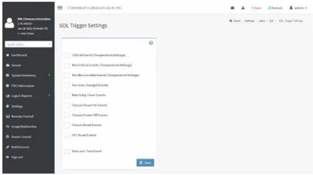
text_image
SOL Trigger Settings Critical Events (Temperature/Voltage) Most Critical Events (Temperature/Voltage) Most Recoverable Events (Temperature/Voltage) Fan state changed Events Watching Time Events Chassis Power On Events Chassis Power Off Events Chassis Reset Events LPC Reset Events Date and Time Event. SaveProcedure
- Check the events to be enabled to configure which event on the page will trigger the SOL video recording option to start.
- To set particular Date and Time Event, check the option Date and Time Event.
a) Choose the month, day and year from the Date field
b) Enter the Time in hh:mm:ss format in the respective fields.

Note: The date and time should be in advance to the system date and time.
- Click Save to save the changes.
SOL Video Remote Storage
This page allows you to configure recorded video files. The sample screenshot and various fields of SOL Video Remote Storage are given below.

text_image
SOL Remote Storage Log Size (KR) 128 Log File Count & Record SQL to Remote Server Server Address Server: R's Host Name Path in server ng fast/fund/Address Share Type NFS OFS SaveProcedure for SOL Video Remote Storage:
- Click SOL Video Remote Storage.
- Enter Log Size (KB). The value will support maximum length of 10 digits.
- Enter Log File Count. The default number of Log files count ranges from 1 to 10.
SOL Recorded Video
This page displays the list of available recorded video files on the system. Click on Download icon to download and save the video. Click on Delete icon to delete the selected video.
A sample screenshot of SOL Recorded Video is given below.

text_image
BMC Firmware Information 2.76.300227 Jun 28 2019 3044/04 CST Quick Links... Dashboard Sensor System Inventory FRU Information Logo & Reports Settings Remote Control Image Redirection Power Control Maintenance Sign out 2019-04-07 21:53:13 (UTC-13:30 UTC) Sol Recorded Files S.No # File Name # File Information # Name - Settings - video - Sol - Sol Recorded FilesJAVA SOL
This page allows you to download JAVA SOL. A sample screenshot of JAVA SOL is given below.

text_image
BMC Features Information 2.76.390327 Jun 28 2019 10:46:04 CST + Quick Order Quick Links. Dashboard Server System Inventory FRU Information Logo & Reports Settings Remote Control Image Redirection Power Control Maintenance Sign out 2019-04-07 21:31:30 (UTC-11:30 UTC) Sync Refresh admin Java SOL To Launch the Java SOL, you must have Administrator privileges. NOTE:A compatible JRE must be installed in the system prior to the launch of JNLP file. Downloaded Java SOL
Note: A compatible JRE must be installed in the system prior to the launch of JNLP file.
2-6-17 Fan Policy
The Fan Policy consists of the following:
- Add New Fan Profile
A sample screenshot of the Fan Profile is given below.
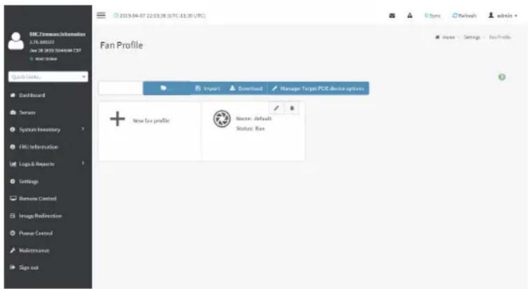
text_image
SBC Features Information 219.880372 Jun 28 2019 7044994 CST Add Online Quick Links... Dashboard Sensor System Boundary FRC Information Logis & Reports Settings Remote Control Image Reflexive Power Control Maintenance Sign out Fan Profile Import Download Manager Target PCE device options + New Tax profile Nurse: default Status: BaseProcedure to add Fan Profile
To add fan profile:
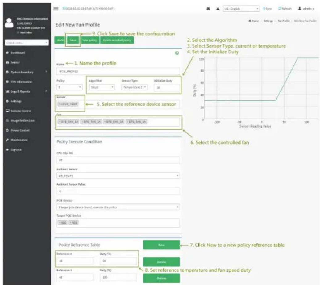
text_image
Edit New Fan Profile 9. Click Save to save the configuration Date: False new policy From serviced policy Name ← 1. Name the profile RTK_PROFILE Policy Algorithm Sensor Type Initiation Duty T SPOG Temperature 2 36 Sensor TCPUE_Terip 5. Select the reference device sensor Data TCPUE_TERIP TCPUE_TERIP TCPUE_TERIP TCPUE_TERIP Policy Execute Condition CPU NAV (M) 40 Ambient Sensor USB_TEMP1 Ambient Sensor Value 0 PCR Device Planned price device hand, execute this policy Target PCR Device +800 -1400 Policy Reference Table New 7. Click New to a new policy reference table Delete 8. Set reference temperature and fan speed duty Delete- Name the the profile
- Select Sensor Type, current or temperature.
- Set the Initialize Type.
- Select the reference device sensor.
- Select the controlled fan.
- Click New to a new policy reference table
- Set reference temperature and fan speed duty
- Click Save to save the configuration.
-
Click arrow icon to run the fan profile.
-
Select the Algorithm. Choose the mapping function of temperature and fan speed at this policy.
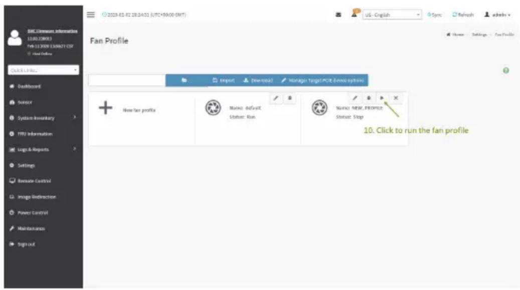
text_image
2023-01-02 28:04:02 (UTC+00:00 GMT) US - English Sync Refresh admin x Fan Profile Home Settings Fan Profile Import Download Manage Target PCCE (new) options + New fan profile Music default Status: Run Music NEW_PROFILE Status: Stop 10. Click to run the fan profile2-6-18 Power Consumption
The Power Consumption is a simple display page for basic power consumption reading information. Item on this page are non-configurable.

text_image
BMC Infrastructure Information 2.76.390207 Jan 28 2019 10/4/2019 GMT Wind Order Quick Links... Dashboard Sensor System Inventory FRU Information Logo & Reports Settings Remote Control Image Redirection Power Control Maintenance Sign out 2019-04-07 22:05:25 (UTC-11:30 UTC) Sync Refresh admin Home Power Consumption Power Consumption Reading Current Power Consumption (W) 40This page intentionally left blank
2-7 Remote Control
The system and browser requirements for Remote Control are given below.
System Requirements
- Client machine with 8GB RAM.
- If the client machine has 4GB RAM, there will be lag in Video/keyboard/mouse functionality.
Supported Browsers
- Chrome latest version.
- IE 11 and above.
- Firefox (with limited support).

Note: It is advisable to use Chrome or IE for H5Viewer, since Firefox has its own memory limitations.
To open Remote Control page, click Remote Control from the menu bar. A sample screenshot of the Remote Control page is shown below.

text_image
BMC Finance Information 2.76.300227 Jan 28 2019 10/4/04 EST + out data Quick Links... Dashboard Sensor System Inventory FRU Information Logs & Reports Settings Remote Control Image Redirection Power Control Maintenance Signs out 2019-04-07 22:19:30 (UTC-11:30 UTC) Remote Control Power Control& Remote iVM & SOL Launch IBM Launch JIMM SOL Home - Remote ControlA detailed description of the menu items are given on the next page.
Open the Remote Control page, click Launch KVM. A sample screenshot of the Remote KVM page is shown below.

text_image
BMC License Information 2.76.300227 Jan 28 2019 (Notional CST) Read Change Quick Links. Dashboard Sensor System Inventory FRU Information Logo & Reports Settings Remote Control Image Redirection Power Control Maintenance Sign out 2019-04-07 22:19:30 (UTC-11:30 UTC) Remote Control Power Control & Remove XML & SQL Launch XML Launch XML SQLClick Launch KVM to open the Remote Control KVM page.
Stop KVM: Stops the H5Viewer video redirection.
Video Record: This menu contains the following sub menu items:
- Record Video: This option is to start recording the screen.
- Stop Recording: This option is used to stop the recording.
Record Settings: This option is used to set Video Recording Duration.

Note: The Maximum video file size allowed is around 40MB. If the video file size reaches max size limit, the recorded file is downloaded and recording will be in progress until the configured video recording time is reached. The video file is saved as video_date-month-year_hr-min-sec_partno in client side video recording.
Users have to take care of saving the video files in different browsers.
When H5viewer focus is lost and if video recording is in progress, the recording will be stopped with a notification message and the recorded video file will be discarded. Due to browser limitation, Set timeout/set interval will be delayed from specified time of interval when browser window loses focus, Hence, video server will not send the video packets to H5viewer and so the video recording will be stopped.

Note: Windows 2016 installation takes 1 hour and 52 minutes to install on Ironman ugh the BMC ISO redirection.
Send Keys: This option is used to key items.
This menu contains the following sub menu items:
- Hold Down
- Press and Release
Hold Down
This menu contains the following sub menu items:
Right Ctrl Key: This menu item can be used to act as the right-side
Right Alt Key: This menu item can be used to act as the right-side
Right Windows Key: This menu item can be used to act as the right-side
Left Ctrl Key: This menu item can be used to act as the left-side
Left Alt Key: This menu item can be used to act as the left-side
Left Windows Key: This menu item can be used to act as the left-side
Press and Release
Ctrl+Alt+Del: This menu item can be used to act as if you depressed the keys down simultaneously on the server that you are redirecting.
Left Windows Key: This menu item can be used to act as the left-side
Right Windows Key: This menu item can be used to act as the right-side
Context Menu Key: This menu item can be used to act as the context menu key, when in Console Redirection.
Print Screen Key: This menu item can be used to act as the print screen key, when in Console Redirection.
Hot Keys: This menu is used to add the user configurable shortcut keys to invoke in the host machine. The configured key events are saved in the BMC.
This menu contains the following sub menu items:
- Add Hot Keys - This menu is used to enable macros. Click Add to macros.
Browse File: Used to select the CD image file to be redirected to the host.
Start Media: Redirects the selected CD image file to the host.
Stop Media: Stops the CD media redirected to the host.
Procedure To Start KVM
- Click Start KVM to start the H5Viewer video redirection. A sample screenshot is as shown below.

text_image
New KFile Video • House • Options • Keyboard • Send Keys • Hot Keys • Video Record • Power • ActiveUsers • Help • Recycle Bin inverter CL980 CL... computing... pushy drive CD Image: Browse File (X KB) Start Menu Access 100%- Click Browse to select CD Image.
- Click Start Media to redirect the selected CD image file to the Host. A sample screenshot is as shown below.
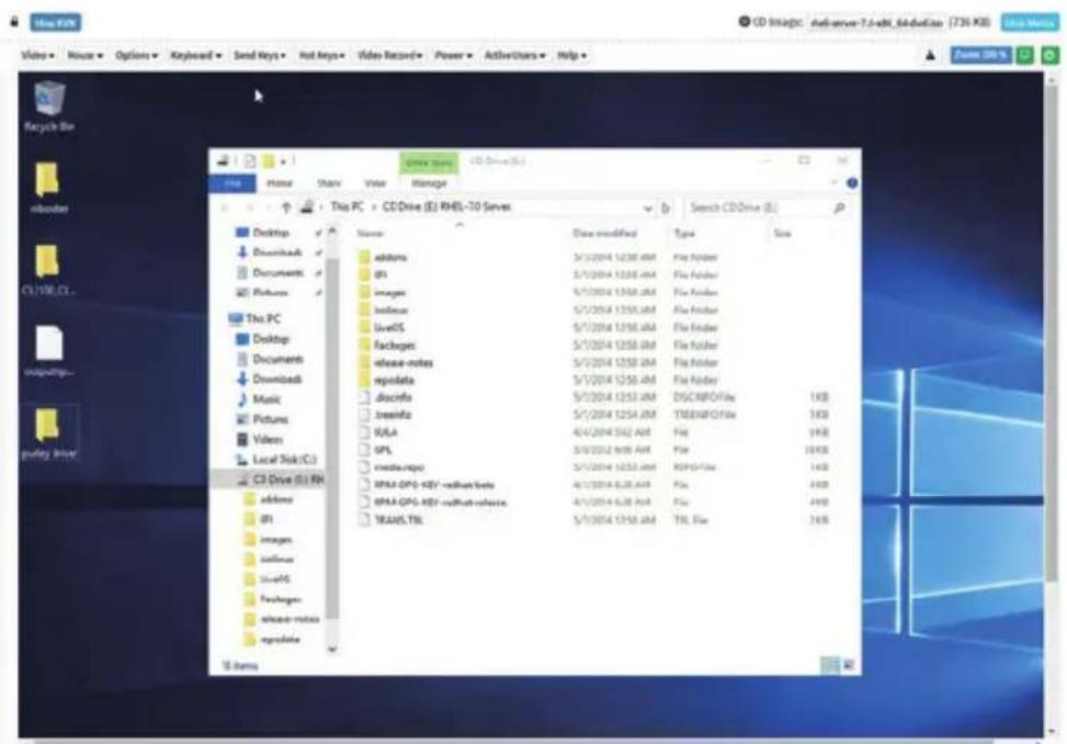
text_image
CD Image: adserver-7.6-akt_4a#eEbox (736 KB) File Edit View Manage This PC > CD Drive (E) RHEL-10 Servers Name Data modified Type Size addams S/1/2014 1238 AM File Folder GPS S/1/2014 1238 AM File Folder images S/1/2014 1250 AM File Folder binless S/1/2014 1250 AM File Folder liveS S/1/2014 1250 AM File Folder packages S/1/2014 1250 AM File Folder release-notes S/1/2014 1250 AM File Folder repdata S/1/2014 1250 AM File Folder discinfo S/1/2014 1253 AM DISCINFO Files 1KB zseinfo S/1/2014 1254 AM TIDEINFO Files 3KB SULA 4/4/2014 562 AM File 9KB GPL S/9/2014 969 AM File 3KB xctos-mgpo S/1/2014 1253 AM ESPD Files 1KB IPAA-GPS KEY-redues/labs S/1/2014 6.28 AM File 4KB IPAA-GPS KEY-redues/labs S/1/2014 6.28 AM File 4KB TEAMS.TIL S/1/2014 1250 AM TIL File 2KB Addams GPS images binless liveS packages release-notes repdata Till Items- To stop the CD Image redirection, click Stop Media.
Settings
Keyboard Layout
List of Host Physical Keyboard languages supported in SPX H5Viewer.
- English U.S
- German
- Japanese
Video
This menu contains the following sub menu items:
Pause Video: This option is used for pausing Console Redirection.
Resume Video: This option is used to resume the Console Redirection when the session is paused.
Refresh Video: This option can be used to update the display shown in the Console Redirection window.
Host Display
Display on: If you disable this option, the display will be shown on the screen in Console Redirection
Display off: If you enable this option, the server display will be blank but you can view the screen in Console Redirection. If you disable this option, the display will be back in the server screen.
Capture Screen: This option helps to take the screenshot of the host screen and save it in the client's system.
Mouse
Show Client Cursor: This menu item can be used to show or hide the local mouse cursor on the remote client system.
Mouse Mode: This option handles mouse emulation from local window to remote screen using either of the two methods. Only 'Administrator' has the right to configure this option.
- Absolute mouse mode: The absolute position of the local mouse is sent to the server if this option is selected.
- Relative mouse mode: The Relative mode sends the calculated relative mouse position displacement to the server if this option is selected.
- Other mouse mode: This mouse mode sets the client cursor in the middle of the client system and will send the deviation to the host. This mouse mode is specific for SUSE Linux installation.

Note: Client cursor will be hidden always. If you want to enable, use Alt + C to access menu.
Options
The Bandwidth Usage option allows you to adjust the bandwidth. You can select one of the following options:
Block Privilege Request: To enable or disable the access privilege of the user.
Keyboard/Mouse Encryption: This option allows you to encrypt keyboard inputs and mouse movements sent between the connections.
0 Best Quality - 7: This option allows you to adjust the screen resolution.
Power
The power options are to perform any power cycle operation. Click on the required option to perform the following operation:
Reset Server: To reboot the system without powering off (warm boot).
Immediate Shutdown: To perform Power OFF Immediately.
Orderly Shutdown: To Power OFF the server in proper order.
Power ON Server: To Power ON the server.
Active Users
Click this option to display the active users and their system ip address.
Active KVM Session can be terminated when there are multiple KVM Session from Master [FULL Privilege KVM Session].
Help
Click this option to get more information About H5Viewer. The KVM Remote Console utility version and plugin version will be displayed.
Zoom 100%
Displays the zoom percentage. Users can click Options from the menu bar and then select Zoom In or Zoom Out to adjust the zoom percentage.
Power ON/OFF
Click this option to Power ON/OFF the server.
2-8 Images Redirection
This page is used to configure the images into BMC for redirection. This can be done either by uploading an image into BMC say, Local Media or by mounting the image from the remote system, Remote Media.
To open Images Redirection page, click Images Redirection from the menu bar. A sample screenshot of Images Redirection page is shown below.

text_image
BMC Software Information 2.76.300227 Jan 28 2019 1044@4.CST + world choice Quick Info... Dashboard Sensor System Inventory FRU Information Logo & Reports Settings Remote Control Image Redirection Power Control Maintenance Sign out 2019-04-07 22:22:10 (UTC-11:30 UTC) Sync Refresh admin Image Redirection Remote ImagesThe fields of Images Redirection page are explained below.
- Local Images
- Remote Images

Note: VMedia Privilege only restricts initiating / starting media redirection. If a device is already being redirected and attached to the host, then in host it will be visible as normal device. Hence it will be accessible to all the KVM sessions. Which includes 'KVM Privilege only' sessions as well.
2-8-1 Remote Media
The displayed table shows configured images on BMC. You can configure images of remote media server.

text_image
BMC Features Information 2.76.390257 Jan 28 2019 10:44:54 CST Next Update Quick Links... Dashboard Sensor System Inventory FRU Information Logo & Reports Settings Remote Control Image Redirection Power Control Maintenance Sign out 2019-04-07 22:25:21 (UTC:11:30 UTC) Remote Media Emulate CQ/DNO HDD images in the network to host as media through BNC Refresh Image List Media Type Media Instance Image Name Redirection Status Connected Server Session Index
Note: More than one image can be configured for each image type. At maximum 4 images can be configurable.
To configure the image, you need to enable Remote Media support under
Settings->Media Redirection -> General Settings.
To start/stop redirection and to delete an image, you must have Administrator Privileges.
Free slots are denoted by "\~"
The fields of Remote Media tab are as follows:
Media Type: Displays type of Media such as CD/DVD, Floppy and Harddisk.
Media Instance: Displays total media instance count.
Image Name: Displays the default recovery image name on the server.
Status: Displays the status of the media.
Session Index: Displays Media Server Session Index.
Start/Stop Redirection: To start or stop Media redirection
Pause: To pause the Media redirection.
Refresh Image List: To get latest Image lists from the Remote Storage.
Procedure
- To Start/Stop Redirection and configure remote media images, click (Start/Stop icon) and make sure Remote Media Support option is enabled.

Note: The Start Redirection button is active only for VMedia enabled users.
Select a configured slot and click (Start/Stop icon) to start the remote media redirection. It is a toggle button, if the image is successfully redirected, then click (Start/Stop icon) to stop the remote media redirection.

Note: Redirection needs to be stopped to clear the image.
2-9 Power Control
This page allows you to view and control the power of your server.
To open Power Control, click Power Control from the menu bar. A sample screenshot of Power Control is shown below.

text_image
BMC Firmware Information 2.7L 300227 Jan 28 2015 10/4/04 CST WAC Online Quick Links... Dashboard Sensor System Inventory FRU Information Logo & Reports Settings Remote Control Image Redirection Power Control Maintenance Sign out 2015-04-07 22:29:52 (UTC-11:30 UTC) Sync Refresh admin Power Control on Host Server Power Actions Host is currently on: Power Off Power On Power Cycle Hard Reset ACM Shutdowns Partners ActiveThe various options of Power Control are given below.
Power Off: To immediately power off the server.
Power On: To power on the server.
Power Cycle: This option will first power off, and then reboot the system (cold boot).
Hard Reset: This option will reboot the system without powering off (warm boot).
ACPI Shutdown: This option to initiate operating system shutdown prior to the shutdown.
Perform Action: Click this option to perform the selected operation.
Procedure
Select an action and click Perform Action to proceed with the selected action.

Note: During Execution you will be asked to confirm your choice. Upon confirmation, you be informed about the status after few minutes.

Note: It is advisable to use Chrome or IE for H5Viewer, since Firefox has its own memory limitations.
2-10 Maintenance Group
This group of pages allows you to do maintenance tasks on the device. The menu contains the following items:
- Backup Configuration
- Firmware Image Location
- Firmware Information
- Firmware Update
- HPM Firmware Update
- Preserve Configuration
- Restore Configuration
- Restore Factory Defaults
- System Administrator
A sample screenshot of Maintenance is shown below.
A detailed description is given below.

text_image
2019-04-07 22:27:19 (UTC-11:30 UTC) Maintenance Backup Configuration Firmware Image Location Firmware Information Firmware Update HPM Firmware Update Preserve Configuration Restore Configuration Restore Factory Defaults System Admin-Istrateur2-10-1 Backup Configuration
This page allows you to select the specific configuration items to be backed up in case of "Backup Configuration".
To open Backup Configuration page, click Maintenance > Backup Configuration from the menu bar. A sample screenshot of Backup Configuration page is shown below.
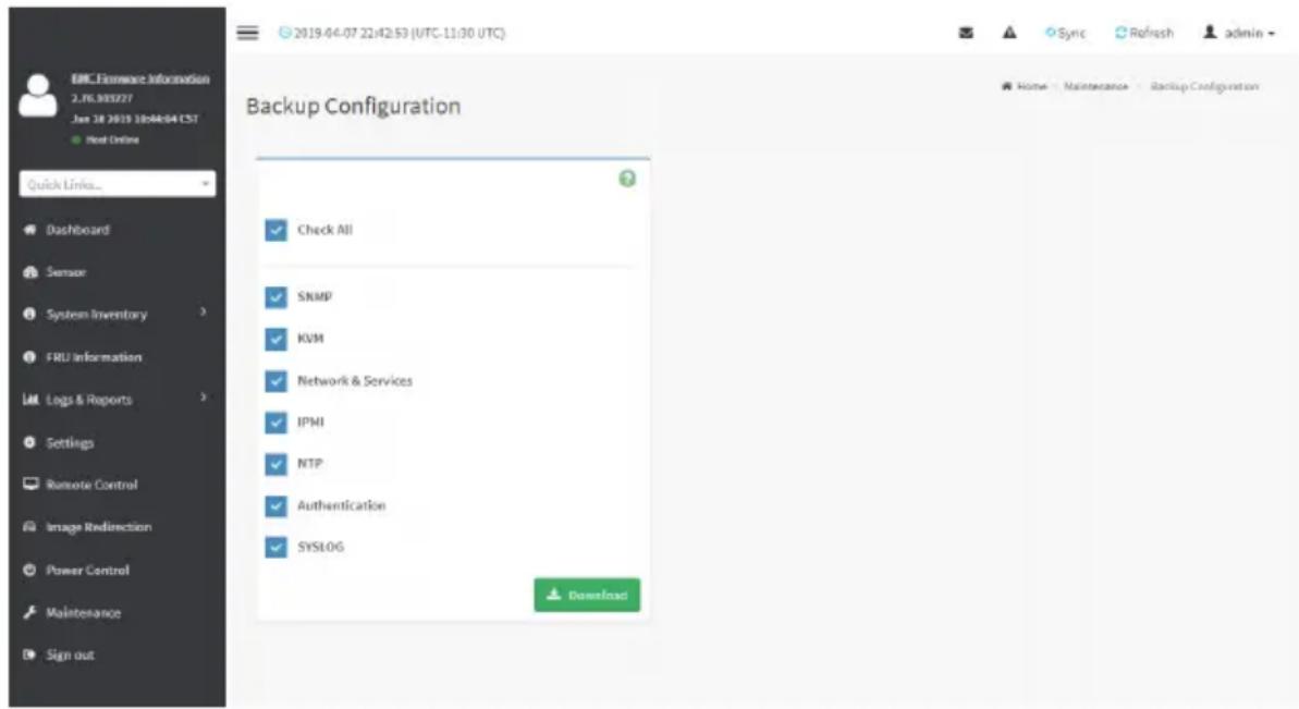
text_image
2019-04-07 22:42:53 (UTC-11:30 UTC) Sync Refresh admin Quick Links... Dashboard Sensor System Inventory FRU Information Logs & Reports Settings Remote Control Image Redirection Power Control Maintenance Sign out Backup Configuration Check All SNMP KVM Network & Services IPMI NTP Authentication SYSLOG DownloadThe various fields of Backup Configuration page are given below.
Check All - To select all the configuration list.
Download Config - To download and save the configuration files backup from BMC to client system.
Procedure
- Click Check All to backup the selected configuration items. The Backup Configuration page will appear as shown above screenshot.
- Click Download Config to save the backup file to the client system.
- Cick OK to perform the backup action. The Backup file will be saved in the client system.
- Click Cancel to cancel the backup process.
TFTP server configuration
The TFTP server configuration is used for exporting the backup file.

Note: Ensure that no other TFTP servers are enabled, if so remove all other servers with configuration files. Login as “super” user means “root” user.
Procedure to make the default tftp server
- Install the application which is needed.
apt-get install xinetd tftp tftpd
- Edit the configuration file for TFTP.
vi /etc/xinetd.d/tftp
Edit the file as below:
service tftp
{
protocol = udp
port = 69
socket_type = dgram
wait = yes
user = nobody
server = /usr/sbin/in.tftpd
server_args = <DIR to which the file to be access>
disable = no
}
#EOF
#example:server_args = /tftpboot
Note: No arguments to be passed to the server_args other than directory.
##########
>vi /etc/xinetd.conf
Add to the file:
defaults
{
<h1 id="please-note-that-you-need-a-log_type-line-to-use-log_on_success-and-log_on_failure">Please note that you need a log_type line to use log_on_success and log_on_failure.</h1>
The default is the following:
<h1 id="log_type-syslog-daemon-info">log_type = SYSLOG daemon info</h1>
}
includedir /etc/xinetd.d
>vi /etc/inetd.conf

ftp stream tcp nowait root /usr/sbin/tcpd /usr/sbin/ in.ftpd
tftp dgram udp wait nobody /usr/sbin/tcpd /usr/sbin/ in.tftpd <DIR>
-
Restart the server.
/etc/init.d/xinetd restart
-
Give permission to the file to access by all.
mkdir
chmod -R 777 chown -R nobody For Example:
mkdir /tftpboot
chmod -R 777 /tftpboot
chown -R nobody /tftpboot
- To receive the file you have to touch the file and give permission to access by all users
touch
/conf.bak chmod 777
/conf.bak
- Even after all this step has been done and still facing error of timeout:
a) Check with /etc/xinetd.d/tftp file and uncomment the EOF (Remove the '# before the EOF alone).
b) Restart the server.
2-10-2 Firmware Image Location
This page is used to configure firmware image into the BMC.
To open Firmware Image Location, click Maintenance > Firmware Image Location from the menu bar.
A sample screenshot of Firmware Image Location page is shown below.

text_image
EMC Firmware Information 2.76.303227 Jan 28 2019 10:46:4 CST ■ Visit Online Quick Links... Dashboard Sensor System Inventory FRLI Information Logs & Reports Settings Remote Control Image Redirection Power Control Maintenance Sign out 2019-04-07 22:43:17 (UTC-11:30 UTC) Firmware Image Location Image Location Type Web Upload during flash TFTP Server Save Home - Maintenance - Firmware Image LocationThe various options of Image Transfer Protocol are given below.
Image Location Type: Type of location to transfer the firmware image into the BMC either Web Upload during Flash or TFTP Server.
TFTP Server Address: Address of the server where the firmware image is stored.

Note: The Server supports both IPv4 and IPv6 addresses
Address made of 4 numbers separated by dots as in "xxx.xxx.xxx.xxx".
Each number ranges from 0 to 255.
First number must not be 0.
IPv6 Address made of 8 groups of 4 Hexadecimal digits separated by colon as in
"XXXX:XXXX:XXXX:XXXX:XXXX:XXXX:XXXX."
Hexadecimal digits are expressed as lower-case letters.
TFTP Image Name: Full Source path with filename of the firmware image is stored on TFTP Server.
TFTP Retry Count: Number of times to be retried in case a transfer failure occurs. Retry count ranges from 0 to 255.
Save: To save the configured settings.
Procedure
- Select the Image Location Type (Web Upload during flash/ TFTP Server).
- If the protocol selected is TFTP, enter the IP address of the server in the TFTP Server Address field.
- Enter the TFTP Image Name in the given field
- Enter the TFTP Retry Count value.
- Click Save to save the changes.
2-10-3 Firmware Update
This wizard takes you through the process of firmware upgradation. A reset of the box will automatically follow if the upgrade is completed or cancelled. An option to Preserve All Configuration is available. Enable it, if you wish to preserve configured settings through the upgrade.

Warning: Please note that after entering update mode widgets, other web pages services will not work. All open widgets will be closed automatically. If upgrade less is cancelled in the middle of the wizard, the device will be reset.

Note: The firmware upgrade process is a crucial operation. Make sure that the chances power or connectivity loss are minimal when performing this operation.
Once you enter into Update Mode and choose to cancel the firmware flash operation, the BMC must be reset. This means that you must close the Internet browser and log back onto the BMC before you can perform any other types of operations.
Once Firmware upgrade using web is started, the regular IPMI command will not be allowed for safety concern if Enable IPMI Command handling during flashing support is disabled in project configuration.
To configure, choose 'Firmware Image Location' under Maintenance. To open Firmware Update page, click Maintenance > Firmware Update from the menu bar.
A sample screenshot of Firmware Update page is shown below.

text_image
Firmware Update 1. The protocol information to be used for Firmware Image transfer during this update is as follows. To configure, choose "Firmware Image Location" under Maintenance. 2. Firmware upgrade is in process. Refreshing this page or Closing this page will interrupt this process and will likely cause the BMC to not work as it should, so it is highly recommended that you do not continue with the refresh or close Page. Protocol Type: HTTP Update Type: BHC Preserve all Configuration. This will preserve all the configuration settings during the Firmware update - irrespective of the individual items marked as preserve/inscribe is the table below. All configuration items below will be preserved as default during the restore configuration reporton. Click "Edit Preserve Configuration" to modify the Preserve status settings. Edit Preserve Configuration S.No Preserve Configuration Item Preserve Status 1 SOR Overwrite 2 FRU Overwrite 3 SEL Overwrite 4 IPMI Overwrite 5 NETWORK Overwrite 6 RTP Overwrite 7 SNMP Overwrite 8 SSR Overwrite 9 IGM Overwrite 10 AUTHENTICATION Overwrite 11 SYSLOG Overwrite 12 WEB Overwrite 13 REDRICH Overwrite Uploaded SignImage Public Key Info Sun Jan 27 15:12:43 2019 New SignImage Public Key Choose File No file chosen Upload Select Firmware Image Choose File No file chosen Start firmware updateThe various fields of Firmware Update are as follows:
-
Preserve all Configuration: To preserve all configuration.
• New signimage Public Key: To select the signimage Public Key to be uploaded. -
Edit Preserve Configuration: To modify the Preserve status settings.
- Select Firmware Image: To select the Firmware image to be uploaded.
- Start Firmware Update: To start the Firmware Update.
This wizard takes you through the process of AMI based firmware upgradation. The protocol information to be used for firmware image transfer during this update is as follows:

Note: All configuration items will be preserved/overwrite as default during the restore nfiguration operation.
Procedure
- Click Preserve all Configuration to preserve all configuration.
- Click Browse to select firmware image. The Firmware update undergoes the following steps:
a) Closing all active client requests
b) Preparing Device for Firmware Upgrade
c) Uploading Firmware Image

Note: A file upload pop-up will be displayed for http/https but in the case of tftp files, there is automatically uploaded displaying the status of upload.
d) Browse and select the Firmware image to flash and click Upload.
e) Click Start firmware update start the Firmware Update. A warning message will be prompted you to proceed further.
f) Click OK to start the Firmware Update. The sample screenshot is shown below
g) Verifying Firmware Image

text_image
Message from webpage We will start the firmware upgrade now. You will not be able to access BMC until it flashes and restarts. Do you want to continue? OK CancelIf flashing is required for all images, please select the following checkbox:
Only the selected sections will be updated:
| Section Name | Existing version | Uploaded version | [ST4C] |
| bcot | 2.4.000000 | 2.4.000000 |  |
| conf | 2.4.000000 | 2.4.000000 |  |
| conf | 2.4.000000 | 0.0. |  |
| root | 2.4.000000 | 2.4.000000 | [26T2] |
| osimage | 2.4.000000 | 2.4.000000 |  |
| www | 2.4.000000 | 2.4.000000 | [TT2K] |
| testapps | 2.4.000000 | 2.4.000000 | [60AX] |
| ast2500e | 0.1.000000 | 0.1.000000 |  |
Flash selected sections
If only few module versions are different, those modules will be flashed.

Note: Only selected sections of the firmware will be updated. Other sections areoped. Before starting flash operation, you are advised to verify the compatibility even image sections.
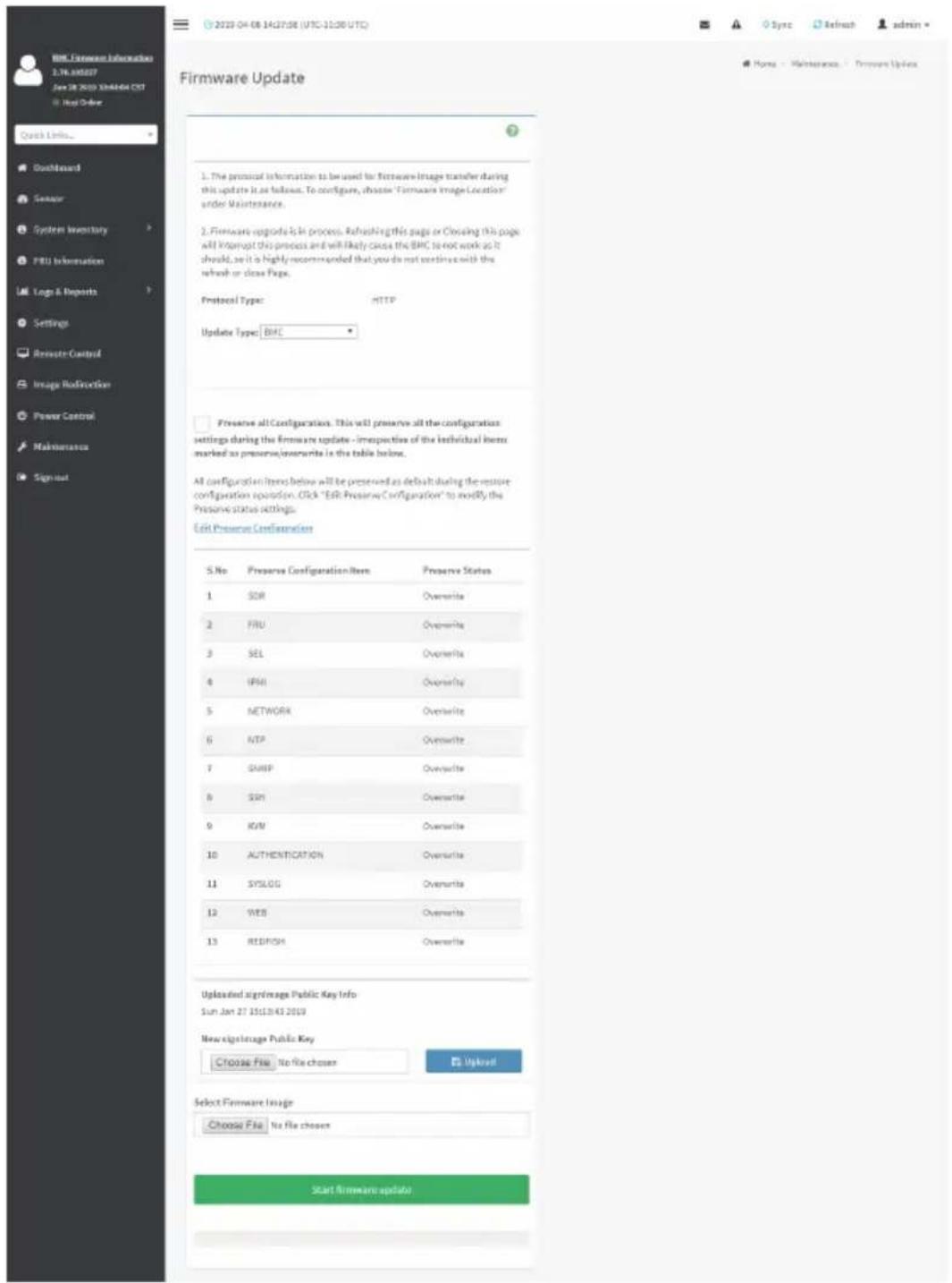
text_image
Firmware Update 1. The protocol information to be used for Firmware Image transfer during this update is as follows. To configure, choose "Firmware Image Location" under Maintenance. 2. Firmware upgrade is in process. Refreshing this page or Closing this page will interrupt this process and will likely cause the BMC to not work as it should, so it is highly recommended that you do not continue with the refresh or close Page. Protocol Type: HTTP Update Type: BHC Preserve all Configuration. This will preserve all the configuration settings during the Firmware update - irrespective of the individual items marked as preserve/inscribe is the table below. All configuration items below will be preserved as default during the restore configuration reporton. Click "Edit Preserve Configuration" to modify the Preserve status settings. Edit Preserve Configuration S.No Preserve Configuration Item Preserve Status 1 SOR Overwrite 2 FRU Overwrite 3 SEL Overwrite 4 IPMI Overwrite 5 NETWORK Overwrite 6 RTP Overwrite 7 SNMP Overwrite 8 SSR Overwrite 9 IGM Overwrite 10 AUTHENTICATION Overwrite 11 SYSLOG Overwrite 12 WEB Overwrite 13 REDRICH Overwrite Uploaded SignImage Public Key Info Sun Jan 27 15:12:43 2019 New SignImage Public Key Choose File No file chosen Upload Select Firmware Image Choose File No file chosen Start firmware updateh) Flashing Firmware Image.
i) Resetting the image. The sample screenshot of Firmware update is as shown below.
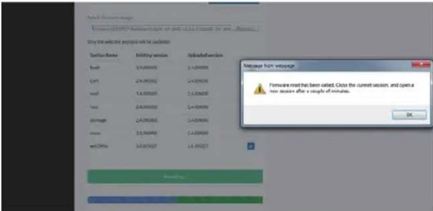
text_image
Only 200 video files will be installed Version Name Building version Uploaded version Book 2.4.08.000 2.4.08.000 Cart 2.4.08.000 2.4.08.000 Model 2.4.08.001 2.4.08.000 Page 2.4.08.002 2.4.08.000 Average 2.4.08.003 2.4.08.000 Success 2.4.08.004 2.4.08.000 end:2996: 2.4.08.007 2.4.08.007 Message from versiona Firmware must have been called. Click the current session, and open a new session after a couple of minutes. OK
Note: The Firmware Update page will be disabled and you will not be able to perform any other tasks until firmware upgrade is completed and the device is rebooted. You can follow the instructions presented in the subsequent pages to successfully update the card's firmware. The device will reset if update is canceled. The device will also reset upon successful completion of firmware update.
2-10-4 HPM Firmware Update
This page allows you to update the HPM (Hardware Platform Management) firmware. To configure, choose 'HPM Firmware Image Location' under Maintenance. To open HPM Firmware Update page, click Maintenance > HPM Firmware Update from the menu bar. A sample screenshot of HPM Firmware Update page is shown below.

text_image
HPM Firmware Update All configuration items below will be preserved as default during the restore configuration operation for BMC Component alone. 1 No Preserve Configuration Item Preserve Status 2 SOR Overwrite 2 FRU Overwrite 3 SEL Overwrite 4 IPMI Overwrite 5 NETWORK Overwrite 6 NTP Overwrite 7 SWIP Overwrite 8 SSH Overwrite 9 KVM Overwrite 10 AUTHENTICATION Overwrite 11 SYSLOG Overwrite 12 NED Overwrite 13 REDFISH Overwrite Uploaded Sign Image Public Key Info Sun Jan 27 15:33:43 2019 New Sign Image Public Key Info Choose File No file chosen 47 Upload Select Firmware Image Choose File No file chosen Start Firmware update WARNING: Please note that after entering the update mode, the widgets, other web pages and services will not work. All the open widgets will be automatically closed. If the upgrading is cancelled in the middle of the wizard, the device will be next.The various fields of HPM Firmware Update are as follows:
- New signimage Public Key: To select the signimage Public Key to be uploaded.
- Select Firmware Image: To select the Firmware image to be uploaded.
- Start Firmware Update: To start the Firmware Update.
This wizard takes you through the process of AMI based firmware upgradation. The protocol information to be used for firmware image transfer during this update is as follows:

Note: All configuration items will be preserved/overwrite as default during the restore configuration operation.
Procedure
- Click Preserve all Configuration to preserve all configuration.
- Click Browse to select firmware image. The Firmware update undergoes the following steps:
a) Closing all active client requests
b) Preparing Device for Firmware Upgrade
c) Uploading Firmware Image

Note: A file upload pop-up will be displayed for http/https but in the case of tftp files, the is automatically uploaded displaying the status of upload.
d) Browse and select the Firmware image to flash and click Upload.
e) Click Start firmware update start the Firmware Update. A warning message will be prompted you to proceed further.
f) Click OK to start the Firmware Update. The sample screenshot is shown below.
10.1.112.70 says:
Are you sure you want to flash?
OK
Cancel
g) Verifying Firmware Image.
If flashing is required for all images, please select the following checkbox:

text_image
Only the selected sections will be updated: Section Name Existing version Uploaded version boot 2.4.000000 2.4.000000 conf 2.4.000000 2.4.000000 conf 2.4.000000 0.0. root 2.4.000000 2.4.000000 osimage 2.4.000000 2.4.000000 www 2.4.000000 2.4.000000 testapps 2.4.000000 2.4.000000 ast2500e 0.1.000000 0.1.000000 Flash selected sectionsIf only few module versions are different, those modules will be flashed.

Note: Only selected sections of the firmware will be updated. Other sections are tipped. Before starting flash operation, you are advised to verify the compatibility between image sections.
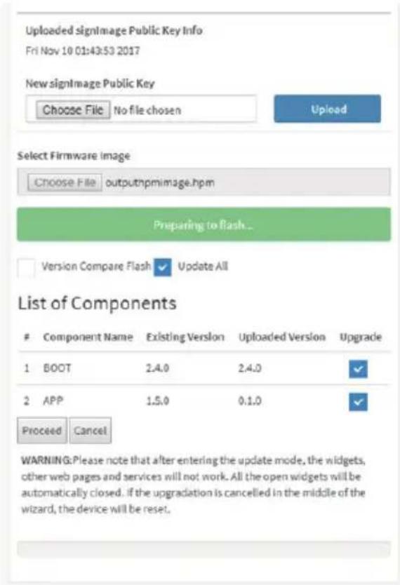
text_image
Uploaded signImage Public Key Info Fri Nov 10 01:43:53 2017 New signImage Public Key Choose File No file chosen Upload Select Firmware Image Choose File outputnpmimage.hpm Preparing to Flash... Version Compare Flash Update All List of ComponentsComponent Name Existing Version Uploaded Version Upgrade
1 BOOT 2.4.0 2.4.0 ✓ 2 APP 1.5.0 0.1.0 ✓ Proceed Cancel WARNING: Please note that after entering the update mode, the widgets, other web pages and services will not work. All the open widgets will be automatically closed. If the upgradation is cancelled in the middle of the wizard, the device will be reset.h) Flashing Firmware Image.
i) Resetting the image. The sample screenshot of Firmware update is as shown below.
10.1.112.70 says:
Firmware reset has been called. Close the current session, and open a new session after a couple of minutes.
OK

Note: The HPM Firmware Update page will be disabled and you will not be able to perform any other tasks until firmware upgrade is completed and the device is rebooted. You can now follow the instructions presented in the subsequent pages to successfully update the card's firmware. The device will reset if update is canceled. The device will also reset upon successful completion of firmware update.
2-10-5 Firmware Information
This wizard takes you through the process of firmware upgradation. A reset of the box will This page is used to configure the Firmware Information settings.
To open System Administrator page, click Maintenance > Firmware Information from the menu bar. A sample screenshot of Firmware Information page is shown below.

text_image
BMCFirmware Information 2.76.300257 Jan 28 2019 10:44:04 CST Host Online Quick Links... Dashboard Sensor System Inventory FRU Information Logo & Reports Settings Remote Control Image Redirection Power Control Maintenance Sign out Firmware Information BMCFirmware Information Build Date Jan 28 2019 Build Time 10:44:04 CST Firmware version 2.76.199227 BIOSFirmware Information Product Manufacturer GIGABITS Product Name MX32-850-99 Build Date 09/03/2018 Firmware version FJtThe various fields of Firmware Information page are given below.
BMC Firmware Information:
Build Date: Describes the Build Date of the active BMC image.
Build Time: Describes the Build Time of the active BMC image.
Firmware version: Describes the Firmware version of the active BMC image.
BIOS Firmware Information:
Product Manufacturer: Describes the hardware manufacturer.
Product Name: Describes the model name of the device.
Build Date: Describes the Build Date of the device.
Firmware version: Describes the BIOS version of the device.
CPLD Firmware Information:
Firmware version: Describes the CPLD Firmware version.
2-10-6 Preserve Configuration
This page allows the user to configure the preserve configuration items, which will be used by the Restore factory defaults to preserve the existing configuration without overwriting with defaults/Firmware Upgrade configuration,
To open Preserve Configuration page, click Maintenance > Preserve Configuration from the menu bar.
A sample screenshot of Preserve Configuration page is shown below.

text_image
BMC License Information 2.76.3003/27 Jan 28, 2019 104:06:04 CST Must Order 2019-04-07 22:47:15 (UTC:11:30 UTC) Preserve Configuration Click here to go to Firmware Update or Restore Factory Defaults Check All SDR FRU SEL PNI Network WTP SNMP SSH KSM Authentication Syslog Web Radfish SaveThe various fields of Preserve Configuration are as follows:
Click here to go to Firmware Update or Restore Configuration: This link will redirect to the Firmware Update or Restore Configuration page which needs to be preserved.
Check All: To check the entire configuration list.
Save: To save the current changes.

Note: This configuration is used by Restore Factory Defaults process.
Files Preserved
SDR
Following files will be preserved:
SDR.dat: This file contains the sensor data record information that is used in IPMI.
Dependency Configurations - NIL
FRU
Following files will be preserved:
FRU.bin: This file contains the logical field replaceable unit data that are used by IPMI.
Dependency Configurations - SDR
FRU
Following files will be preserved:
FRU.bin: This file contains the logical field replaceable unit data that are used by IPMI.
Dependency Configurations - SDR
SEL
Following files will be preserved when Delete SEL reclaim space is disabled:
SEL.dat: This file contains the system event logs that are being logged by the IPMI.
Following files will be preserved when Delete SEL reclaim space is enabled:
Selreclaiminfo.ini - The file contains the SEL repository information.
SEL folder - This folder contains the multiple files of event logs.
Dependency Configurations - IPMI
IPMI
The following files are preserved in IPMI configuration:
IPMI.conf: This file contains the IPMI configurations such as SEL rep size, SDR rep size, interface specific, enable/disable, Primary/Secondary, IPMB Bus number etc.
Dependency Configurations - NIL
Network
To save network settings related with IPMI (LAN IP or DHCP configuration), select “IPMI” and “Network” options simultaneously. After restore configuration, the Network Configuration will be preserved successfully. Following files will also be preserved:
dhcp.conf: This file is to configure the host name in the FQDN format.
dns.conf: This file is used to configure the DNS registration method and DNS server for the particular interface, hostname: This file is used to store the Hostname of the BMC.
hostname.conf: This file is used to configure the host name creation method Manual/Automatic for the BMC.
Vlaninterfaces: This file helps to enable the vlan interface for the particular LAN interface
vlansetting.conf: This file is to store the vlan ID and Vlan priority for the particular VLAN interface entry.
bond.conf: This file is to enable the bond interface for the specified LAN interfaces.
Interfaces: This file is to configure the IP/IPV6 addresses for the LAN interface using static/DHCP method.
activeslave.conf: This file is to configure the active interface for the specified bond interface.
This file depends on bond.conf.
hosts: This file is used to store the host name to map the IP address.
hosts.allow: This file contains the list of hosts that has permission to access the system
hosts.deny: This file contains the list of host that does not allow accessing the system
resolv.conf: This file is used to store the nameserver and domain name for hostname
registration.
dhcp6c-script: This file is used to configure the domain name, DNS server IPv6 address and NTP address.
dhcp6c.conf: This file is to configure the IPv6 parameters for the DHCPv6 clients.
ncsicfg.conf: This file is to configure the NCSI related configurations.
nsupdate.conf: This file is to configure the channel ID, package ID for the NCSI interface.
phycfg.conf: This file is to configure the link speed, duplex and MTU value for the specified interface.
dhcp.preip_4: This file is to store the pre IPv4 address. This file will be created at runtime.
dns.conf: This file is used to configure the DNS registration method and DNS server for the particular interface.
hostname: This file is used to store the Hostname of the BMC.
hostname.conf: This file is used to configure the host name creation method Manual/Automatic for the BMC.
Vlaninterfaces: This file helps to enable the vlan interface for the particular LAN interface
vlansetting.conf: This file is to store the vlan ID and Vlan priority for the particular VLAN interface entry.
bond.conf: This file is to enable the bond interface for the specified LAN interfaces.
Interfaces: This file is to configure the IP/IPV6 addresses for the LAN interface using static/DHCP method.
activeslave.conf: This file is to configure the active interface for the specified bond interface. This file depends on bond.conf.
hosts: This file is used to store the host name to map the IP address.
hosts.allow: This file contains the list of hosts that has permission to access the system
hosts.deny: This file contains the list of host that does not allow accessing the system
resolv.conf: This file is used to store the nameserver and domain name for hostname registration.
dhcp6c-script: This file is used to configure the domain name, DNS server IPv6 address and NTP address.
dhcp6c.conf: This file is to configure the IPv6 parameters for the DHCPv6 clients.
ncsicfg.conf: This file is to configure the NCSI related configurations.
nsupdate.conf: This file is to configure the channel ID, package ID for the NCSI interface.
phycfg.conf: This file is to configure the link speed, duplex and MTU value for the specified interface.
dhcp.preip_4: This file is to store the pre IPv4 address. This file will be created at runtime.
NTP
Following files will be preserved:
ntp.conf: This file contains the NTP dameon protocol configuration parameters such as synchronization sources, nodes and other related information
ntp.stat: This file contains the auto or manual network type protocols
adjtime: This file contains the time to synchronize the system clock
Localtime: This file is the system link to the file local time or to the correct time zone in the system timezone directly.
Dependency Configurations - IPMI
SNMP
Following files will be preserved:
snmp_users.conf: This file contains the SNMP user configurations such as user name and password encryption mechanism for the specific users.
snmpcfg.conf: This file contains the SNMP users privilege levels such as ro user and rw user.
Dependency Configurations - NIL
SSH
Following files will be preserved:
sshd_config: This file contains the keyword argument pairs of configurations such as Address family, Accept Env, Allow, users, authorized key files etc.
ssh_host_dsa_key, ssh_host_rsa_key: These files contain the private parts of the host keys.
ssh_host_dsa_key.pub, ssh_host_rsa_key.pub: These files contain the public parts of the host keys.
Dependency Configurations - NIL
KVM
Following files will be preserved:
vmedia.conf: This file contains the modes of media such as cd,fd,hd and enable and disable flags for lmedia, rmedia and sd servers.
stunnel.conf: This file contains the information about the stunnel configuration. It will also contain advisor and media server's secure port if secure connection is enabled.
usermacro.conf: This file saves the user defined macro from the jviewer.
rmedia.conf: This file contains the image name and the remote machine information like IP address, user name, password, domain name and share type.
Dependency Configurations - NIL
Authentication
Following files will be preserved:
activatedir.conf: This file contains the configurations such as sslenable, timeout, racdomain, adtype, adfilterdc1, adfilterdc2, adfilterdc3, username, password, and rolegroup information such as name domain and privileges.
openLdapGroup.conf: This file contains the oprnm ldap role group information such as name domain and privilege.
nsswitch.conf: This file contains the sources to obtain the name service information in the range of categories and in what order
pam_withunix: This file contains the PAM Order of modules such as IPMI, LDAP, RADIUS and UNIX.
pam_wounix: This contains the PAM Order of modules such as IPMI, LDAP and RADIUS.
group: This file contains the Linux group. It stores the group information or defines the user group information in Linux.
passwd: This file contains the user login information for the Linux system
shadow: This file contains the encrypted password information for the clients.
ldap.conf: This file contains the ldap server configuration details such as bindn, binpw, pam_password, nss_reconnect_tries, port, port secondary, host, host secondary.
radius.conf: This file contains the radius server IP address, port number, secret, timeout, privilege etc.
Dependency Configurations – NIL
Syslog
System Event Log
Web
Web Settings
Extlog
Audit Log & System Log
Redish
Redfish Audit Log
Procedure
-
Click Firmware Update or Restore Configuration link to view Firmware Update or Restore Configuration page accordingly.
-
Select the required Preserve Configuration items by either choosing the items individually by selecting the appropriate check boxes or by selecting all or none using Check All.
-
Click Save to save the changes.
2-10-7 Restore Configuration
This page allows you to restore the configuration files from the client system to the BMC.
To open Restore Configuration page, click Maintenance >Restore Configuration from the menu bar. A sample screenshot of Restore Configuration page is shown below.
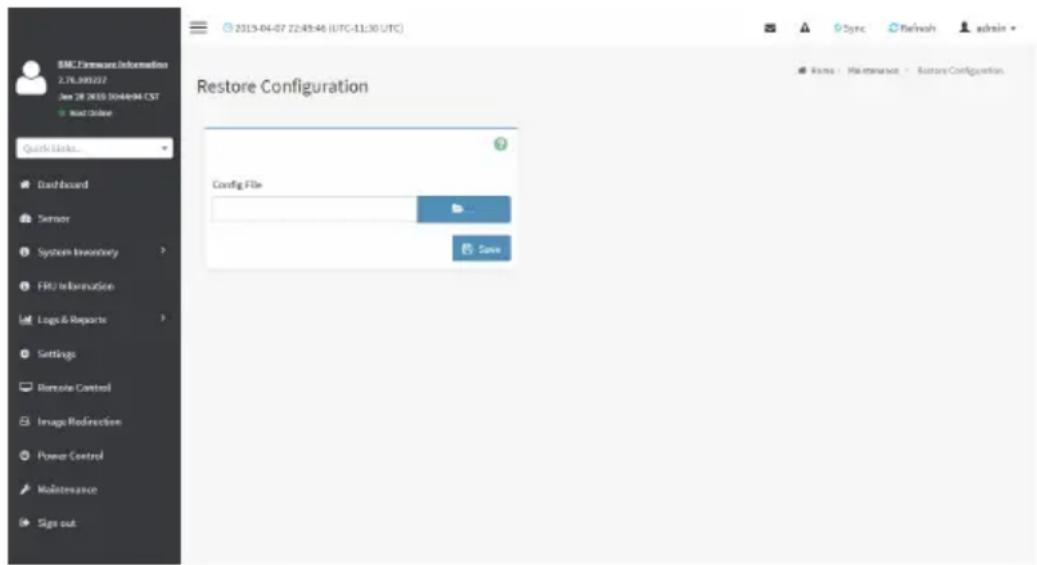
text_image
BMC Features Information 2.7L 300227 Dec 28 2010 304494 EST Quick Links... Dashboard Server System Inventory FRU Information Logo & Reports Settings Remote Control Image Redirection Power Control Maintenance Sign out 2013-04-07 22:45:46 (UTC-11:30 UTC) Restore Configuration Config File Save Sync Refresh admin Name Maintenance Restore ConfigurationThe various fields Restore Configuration page are given below.
Config File - This option is used to select the file which was backup earlier.
Upload - To upload the backup file to restore the backup files.
Procedure for Restore Configuration:
- Click Browse to select the configuration file that needs to be backup and used to restore the configuration, when needed.
- Click Upload to restore the backup files. The Restore Configuration page will appear as shown below.
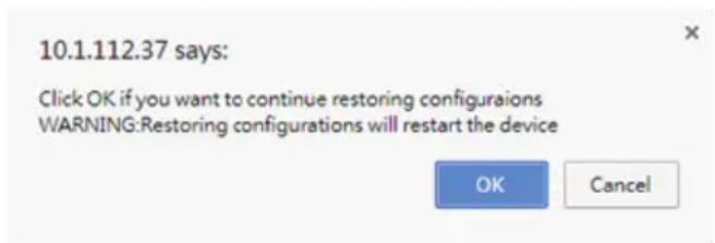
text_image
10.1.112.37 says: Click OK if you want to continue restoring configuraions WARNING:Restoring configurations will restart the device OK Cancel- Click OK to upload the new configuration file and restore.
2-10-8 Restore Factory Defaults
In BMC Web GUI, this option is used to restore the factory defaults of the device firmware. This section lists the configuration items that will be preserved during restore factory default configuration.

Warning: Please note that after entering restore factory widgets, other web pages and faces will not work. All open widgets will be closed automatically. The device will reset reboot within few minutes.
To open Restore Factory Defaults page, click Maintenance >Restore Factory Defaults from the menu bar. A sample screenshot of Restore Factory Defaults page is shown below.
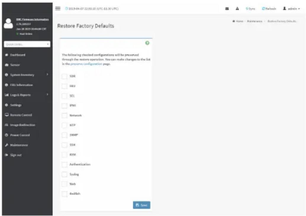
text_image
BMC Firmware Information L7L.390227 Jan 28 2019 20:44:04 CST + Start Online Quick Links... Dashboard Sensor System Inventory FRU Information Logs & Reports Settings Remote Control Image Redirection Power Control Maintenance Sign out Restore Factory Defaults The following checked configurations will be preserved through the restore operation. You can make changes to the list in the preserve configuration page. SDR ERU SEL IPMI Network NTP SMMP SSH KYM Authentication Syslog Web Redfish SaveProcedure
- Click Preserve Configuration to redirect to Preserve Configuration page, which is used to preserve the particular configuration not to be overwritten by the default configuration.
- Click Restore Factory Defaults to restore the factory defaults of the device firmware
2-10-9 System Administrator
This page is used to configure the System Administrator settings.
To open System Administrator page, click Maintenance > System Administrator from the menu bar. A sample screenshot of System Administrator page is shown below.
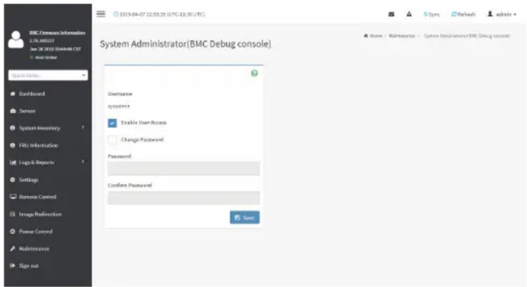
text_image
BMC Features Information 2.78.300227 Date: 28/2019/04/06/04 EST Quick Links... Dashboard Server System Inventory FRU Information Logo & Reports Settings Remote Control Image Redirection Power Control Maintenance Sign out 2019-04-07 22:50:25 (UTC-11:30 UTC) System Administrator(BMC Debug console) Username systemdrive Enable User Access Change Password Password Confins Password Send Home - Maintenance - System Administrator(BMC Debug console)The various fields of System Administrator page are given below.
Username: Username of System Administrator is a read only field.
Enable User Access: To enable user access for system administrator.
Change Password: To change the user's password.

Note: This field will not allow more than 64 characters.
Password must be at least 8 characters long and blank space is not allowed.
Save: To save the new configuration for system administrator.
Procedure
- Check Enable User Access to enable user access for system administrator..
- Enable Change Password option to change the user password. This action enables the password fields.
- Enter the new password in the Password field.
- Re-enter the password in the Confirm Password field.
- Click Save to save the changes.
2-10-10 Sign Out
To log out from the Web GUI, click the admin on the top right corner of the screen. A sample screenshot of admin option is shown below.

text_image
admin - Administrator Profile Sign outClick Sign Out to perform log out from the Web GUI. A Warning message will be prompted you to proceed further, click OK to log out else Cancel to retain the Web GUI.